EP3791965A1 - Method and device for dosing and coating - Google Patents
Method and device for dosing and coating Download PDFInfo
- Publication number
- EP3791965A1 EP3791965A1 EP20203577.0A EP20203577A EP3791965A1 EP 3791965 A1 EP3791965 A1 EP 3791965A1 EP 20203577 A EP20203577 A EP 20203577A EP 3791965 A1 EP3791965 A1 EP 3791965A1
- Authority
- EP
- European Patent Office
- Prior art keywords
- holding body
- applicator
- supply unit
- distribution pipe
- arrangement
- Prior art date
- Legal status (The legal status is an assumption and is not a legal conclusion. Google has not performed a legal analysis and makes no representation as to the accuracy of the status listed.)
- Granted
Links
Images




Classifications
-
- B—PERFORMING OPERATIONS; TRANSPORTING
- B05—SPRAYING OR ATOMISING IN GENERAL; APPLYING FLUENT MATERIALS TO SURFACES, IN GENERAL
- B05C—APPARATUS FOR APPLYING FLUENT MATERIALS TO SURFACES, IN GENERAL
- B05C1/00—Apparatus in which liquid or other fluent material is applied to the surface of the work by contact with a member carrying the liquid or other fluent material, e.g. a porous member loaded with a liquid to be applied as a coating
- B05C1/04—Apparatus in which liquid or other fluent material is applied to the surface of the work by contact with a member carrying the liquid or other fluent material, e.g. a porous member loaded with a liquid to be applied as a coating for applying liquid or other fluent material to work of indefinite length
- B05C1/08—Apparatus in which liquid or other fluent material is applied to the surface of the work by contact with a member carrying the liquid or other fluent material, e.g. a porous member loaded with a liquid to be applied as a coating for applying liquid or other fluent material to work of indefinite length using a roller or other rotating member which contacts the work along a generating line
- B05C1/0813—Apparatus in which liquid or other fluent material is applied to the surface of the work by contact with a member carrying the liquid or other fluent material, e.g. a porous member loaded with a liquid to be applied as a coating for applying liquid or other fluent material to work of indefinite length using a roller or other rotating member which contacts the work along a generating line characterised by means for supplying liquid or other fluent material to the roller
-
- B—PERFORMING OPERATIONS; TRANSPORTING
- B05—SPRAYING OR ATOMISING IN GENERAL; APPLYING FLUENT MATERIALS TO SURFACES, IN GENERAL
- B05D—PROCESSES FOR APPLYING FLUENT MATERIALS TO SURFACES, IN GENERAL
- B05D1/00—Processes for applying liquids or other fluent materials
- B05D1/26—Processes for applying liquids or other fluent materials performed by applying the liquid or other fluent material from an outlet device in contact with, or almost in contact with, the surface
-
- B—PERFORMING OPERATIONS; TRANSPORTING
- B05—SPRAYING OR ATOMISING IN GENERAL; APPLYING FLUENT MATERIALS TO SURFACES, IN GENERAL
- B05C—APPARATUS FOR APPLYING FLUENT MATERIALS TO SURFACES, IN GENERAL
- B05C1/00—Apparatus in which liquid or other fluent material is applied to the surface of the work by contact with a member carrying the liquid or other fluent material, e.g. a porous member loaded with a liquid to be applied as a coating
- B05C1/04—Apparatus in which liquid or other fluent material is applied to the surface of the work by contact with a member carrying the liquid or other fluent material, e.g. a porous member loaded with a liquid to be applied as a coating for applying liquid or other fluent material to work of indefinite length
- B05C1/08—Apparatus in which liquid or other fluent material is applied to the surface of the work by contact with a member carrying the liquid or other fluent material, e.g. a porous member loaded with a liquid to be applied as a coating for applying liquid or other fluent material to work of indefinite length using a roller or other rotating member which contacts the work along a generating line
- B05C1/0817—Apparatus in which liquid or other fluent material is applied to the surface of the work by contact with a member carrying the liquid or other fluent material, e.g. a porous member loaded with a liquid to be applied as a coating for applying liquid or other fluent material to work of indefinite length using a roller or other rotating member which contacts the work along a generating line characterised by means for removing partially liquid or other fluent material from the roller, e.g. scrapers
-
- B—PERFORMING OPERATIONS; TRANSPORTING
- B05—SPRAYING OR ATOMISING IN GENERAL; APPLYING FLUENT MATERIALS TO SURFACES, IN GENERAL
- B05C—APPARATUS FOR APPLYING FLUENT MATERIALS TO SURFACES, IN GENERAL
- B05C1/00—Apparatus in which liquid or other fluent material is applied to the surface of the work by contact with a member carrying the liquid or other fluent material, e.g. a porous member loaded with a liquid to be applied as a coating
- B05C1/04—Apparatus in which liquid or other fluent material is applied to the surface of the work by contact with a member carrying the liquid or other fluent material, e.g. a porous member loaded with a liquid to be applied as a coating for applying liquid or other fluent material to work of indefinite length
- B05C1/08—Apparatus in which liquid or other fluent material is applied to the surface of the work by contact with a member carrying the liquid or other fluent material, e.g. a porous member loaded with a liquid to be applied as a coating for applying liquid or other fluent material to work of indefinite length using a roller or other rotating member which contacts the work along a generating line
- B05C1/0826—Apparatus in which liquid or other fluent material is applied to the surface of the work by contact with a member carrying the liquid or other fluent material, e.g. a porous member loaded with a liquid to be applied as a coating for applying liquid or other fluent material to work of indefinite length using a roller or other rotating member which contacts the work along a generating line the work being a web or sheets
- B05C1/083—Apparatus in which liquid or other fluent material is applied to the surface of the work by contact with a member carrying the liquid or other fluent material, e.g. a porous member loaded with a liquid to be applied as a coating for applying liquid or other fluent material to work of indefinite length using a roller or other rotating member which contacts the work along a generating line the work being a web or sheets being passed between the coating roller and one or more backing rollers
-
- B—PERFORMING OPERATIONS; TRANSPORTING
- B05—SPRAYING OR ATOMISING IN GENERAL; APPLYING FLUENT MATERIALS TO SURFACES, IN GENERAL
- B05C—APPARATUS FOR APPLYING FLUENT MATERIALS TO SURFACES, IN GENERAL
- B05C1/00—Apparatus in which liquid or other fluent material is applied to the surface of the work by contact with a member carrying the liquid or other fluent material, e.g. a porous member loaded with a liquid to be applied as a coating
- B05C1/04—Apparatus in which liquid or other fluent material is applied to the surface of the work by contact with a member carrying the liquid or other fluent material, e.g. a porous member loaded with a liquid to be applied as a coating for applying liquid or other fluent material to work of indefinite length
- B05C1/08—Apparatus in which liquid or other fluent material is applied to the surface of the work by contact with a member carrying the liquid or other fluent material, e.g. a porous member loaded with a liquid to be applied as a coating for applying liquid or other fluent material to work of indefinite length using a roller or other rotating member which contacts the work along a generating line
- B05C1/0826—Apparatus in which liquid or other fluent material is applied to the surface of the work by contact with a member carrying the liquid or other fluent material, e.g. a porous member loaded with a liquid to be applied as a coating for applying liquid or other fluent material to work of indefinite length using a roller or other rotating member which contacts the work along a generating line the work being a web or sheets
- B05C1/0834—Apparatus in which liquid or other fluent material is applied to the surface of the work by contact with a member carrying the liquid or other fluent material, e.g. a porous member loaded with a liquid to be applied as a coating for applying liquid or other fluent material to work of indefinite length using a roller or other rotating member which contacts the work along a generating line the work being a web or sheets the coating roller co-operating with other rollers, e.g. dosing, transfer rollers
-
- B—PERFORMING OPERATIONS; TRANSPORTING
- B05—SPRAYING OR ATOMISING IN GENERAL; APPLYING FLUENT MATERIALS TO SURFACES, IN GENERAL
- B05C—APPARATUS FOR APPLYING FLUENT MATERIALS TO SURFACES, IN GENERAL
- B05C11/00—Component parts, details or accessories not specifically provided for in groups B05C1/00 - B05C9/00
- B05C11/02—Apparatus for spreading or distributing liquids or other fluent materials already applied to a surface ; Controlling means therefor; Control of the thickness of a coating by spreading or distributing liquids or other fluent materials already applied to the coated surface
- B05C11/04—Apparatus for spreading or distributing liquids or other fluent materials already applied to a surface ; Controlling means therefor; Control of the thickness of a coating by spreading or distributing liquids or other fluent materials already applied to the coated surface with blades
- B05C11/041—Apparatus for spreading or distributing liquids or other fluent materials already applied to a surface ; Controlling means therefor; Control of the thickness of a coating by spreading or distributing liquids or other fluent materials already applied to the coated surface with blades characterised by means for positioning, loading, or deforming the blades
- B05C11/042—Apparatus for spreading or distributing liquids or other fluent materials already applied to a surface ; Controlling means therefor; Control of the thickness of a coating by spreading or distributing liquids or other fluent materials already applied to the coated surface with blades characterised by means for positioning, loading, or deforming the blades allowing local positioning, loading or deforming along the blades
-
- B—PERFORMING OPERATIONS; TRANSPORTING
- B05—SPRAYING OR ATOMISING IN GENERAL; APPLYING FLUENT MATERIALS TO SURFACES, IN GENERAL
- B05C—APPARATUS FOR APPLYING FLUENT MATERIALS TO SURFACES, IN GENERAL
- B05C5/00—Apparatus in which liquid or other fluent material is projected, poured or allowed to flow on to the surface of the work
-
- B—PERFORMING OPERATIONS; TRANSPORTING
- B05—SPRAYING OR ATOMISING IN GENERAL; APPLYING FLUENT MATERIALS TO SURFACES, IN GENERAL
- B05C—APPARATUS FOR APPLYING FLUENT MATERIALS TO SURFACES, IN GENERAL
- B05C5/00—Apparatus in which liquid or other fluent material is projected, poured or allowed to flow on to the surface of the work
- B05C5/02—Apparatus in which liquid or other fluent material is projected, poured or allowed to flow on to the surface of the work the liquid or other fluent material being discharged through an outlet orifice by pressure, e.g. from an outlet device in contact or almost in contact, with the work
- B05C5/0254—Coating heads with slot-shaped outlet
-
- B—PERFORMING OPERATIONS; TRANSPORTING
- B05—SPRAYING OR ATOMISING IN GENERAL; APPLYING FLUENT MATERIALS TO SURFACES, IN GENERAL
- B05C—APPARATUS FOR APPLYING FLUENT MATERIALS TO SURFACES, IN GENERAL
- B05C5/00—Apparatus in which liquid or other fluent material is projected, poured or allowed to flow on to the surface of the work
- B05C5/02—Apparatus in which liquid or other fluent material is projected, poured or allowed to flow on to the surface of the work the liquid or other fluent material being discharged through an outlet orifice by pressure, e.g. from an outlet device in contact or almost in contact, with the work
- B05C5/0254—Coating heads with slot-shaped outlet
- B05C5/0262—Coating heads with slot-shaped outlet adjustable in width, i.e. having lips movable relative to each other in order to modify the slot width, e.g. to close it
-
- B—PERFORMING OPERATIONS; TRANSPORTING
- B05—SPRAYING OR ATOMISING IN GENERAL; APPLYING FLUENT MATERIALS TO SURFACES, IN GENERAL
- B05C—APPARATUS FOR APPLYING FLUENT MATERIALS TO SURFACES, IN GENERAL
- B05C11/00—Component parts, details or accessories not specifically provided for in groups B05C1/00 - B05C9/00
- B05C11/02—Apparatus for spreading or distributing liquids or other fluent materials already applied to a surface ; Controlling means therefor; Control of the thickness of a coating by spreading or distributing liquids or other fluent materials already applied to the coated surface
-
- B—PERFORMING OPERATIONS; TRANSPORTING
- B05—SPRAYING OR ATOMISING IN GENERAL; APPLYING FLUENT MATERIALS TO SURFACES, IN GENERAL
- B05C—APPARATUS FOR APPLYING FLUENT MATERIALS TO SURFACES, IN GENERAL
- B05C11/00—Component parts, details or accessories not specifically provided for in groups B05C1/00 - B05C9/00
- B05C11/02—Apparatus for spreading or distributing liquids or other fluent materials already applied to a surface ; Controlling means therefor; Control of the thickness of a coating by spreading or distributing liquids or other fluent materials already applied to the coated surface
- B05C11/023—Apparatus for spreading or distributing liquids or other fluent materials already applied to a surface
- B05C11/025—Apparatus for spreading or distributing liquids or other fluent materials already applied to a surface with an essentially cylindrical body, e.g. roll or rod
-
- B—PERFORMING OPERATIONS; TRANSPORTING
- B05—SPRAYING OR ATOMISING IN GENERAL; APPLYING FLUENT MATERIALS TO SURFACES, IN GENERAL
- B05C—APPARATUS FOR APPLYING FLUENT MATERIALS TO SURFACES, IN GENERAL
- B05C11/00—Component parts, details or accessories not specifically provided for in groups B05C1/00 - B05C9/00
- B05C11/10—Storage, supply or control of liquid or other fluent material; Recovery of excess liquid or other fluent material
- B05C11/1039—Recovery of excess liquid or other fluent material; Controlling means therefor
-
- B—PERFORMING OPERATIONS; TRANSPORTING
- B05—SPRAYING OR ATOMISING IN GENERAL; APPLYING FLUENT MATERIALS TO SURFACES, IN GENERAL
- B05C—APPARATUS FOR APPLYING FLUENT MATERIALS TO SURFACES, IN GENERAL
- B05C9/00—Apparatus or plant for applying liquid or other fluent material to surfaces by means not covered by any preceding group, or in which the means of applying the liquid or other fluent material is not important
- B05C9/04—Apparatus or plant for applying liquid or other fluent material to surfaces by means not covered by any preceding group, or in which the means of applying the liquid or other fluent material is not important for applying liquid or other fluent material to opposite sides of the work
Definitions
- the present invention relates to an applicator arrangement including a distribution pipe and is a divisional from EP-A-12752932.9 , focusing on the design of the applicator device.
- the so called blade coating technique is a prior art method for the coating of running webs.
- This technique that exists in lots of varieties is based on the principle that a coating medium (colour, starch for example) surplus is supplied at a surplus to the web at a position prior to a final dosing metering means.
- Said final dosing and metering means may be composed of structure combined with thin flexible blades, rigid blades or rods that, similar to puttying, doses out and applies the amount of coating medium, see for example WO 2007/061378 which is herewith incorporated by reference.
- the dosing and coating means are comprised in an applicator arrangement, which for instance comprises means for handling the surplus of the coating medium, which is returned for circulation and reuse by the arrangement.
- Prior art applicator arrangements present several disadvantages, e.g. having a bulky and relatively complex structure.
- a coating device for directly or indirectly applying a coating medium onto a running paper- or board web is shown.
- the device includes nozzle lips of which at least one is being formed by a blade element. By applying an elastic nozzle lip, the nozzle gap can be enlarged.
- the coating device includes a mechanism for adjusting the height of the nozzle gap.
- a related problem within the field of dosing and coating arrangements is that the coating medium mostly has to be supplied at a temperature that is different (normally higher) compared to ambient temperature, in combination with the fact that the total applicator arrangement is relatively large, i.e. extends over the cross machine width. As consequence there may result temperature gradients causing bending of the applicator arrangement, which may result in coat weight variations. In many applicator arrangements, e.g. US 5772766 , there are no arrangement to counter act this negative effect. According to some prior art this problem is commonly handled by costly and bulky temperature control structures, e.g. as shown in EP 0 931 878 . This prior art document describes a fountain coating applicator presenting an alternative manner of handling the latter problem, i.e. the tendency of heated coating to cause a temperature gradient is counteracted by cantilevering the applicator head on arms from a support beam through which a temperature-controlling fluid is circulated.
- an applicator arrangement which is very compact and does not require as much space as prior art technique does. Investment costs may be smaller and the accessibility of the arrangement may make maintenance and reparations easier and cheaper. According to a preferred embodiment this achieved by an applicator arrangement wherein means for distribution of coating medium and scraping off a surplus of coating medium are in the form of integrated units.
- the applicator arrangement comprises a supply unit for supply of coating liquid/slurry, an applicator device and a metering device, wherein said supply unit forms a support for both of said applicator device and metering device, and wherein both of said applicator device and/or metering device are directly or indirectly attached to said supply unit.
- said supply unit comprises a distribution pipe which in its turn is supported by a support body by means of a bearing arrangement arranged to enable axial expansion and contraction of said distribution pipe.
- said supply unit forms a support body for said applicator device and/or metering device in the sense that it receives forces transmitted from said applicator device and/or metering device upon operation.
- This means according to the invention at least a majority of the forces applied from the applicator device and/or metering device upon use are arranged to be spread to and distributed within the body which constitutes said supply unit.
- said supply unit is in the form of a distribution pipe or tube, preferably a circular tube of a metallic non welded design, more preferred a standard tube, which provides a much more cost-efficient pressure vessel than traditionally used supply vessels.
- said distribution pipe is supported by a support body by means of a bearing arrangement arranged to enable axial expansion and contraction of said distribution pipe, wherein preferably said support body is in the form of a tube, more preferred of a low alloy steel material.
- a holding body for an applicator arrangement according to claim 1, wherein said metering element is attached to, and held by said holding body, which also forms one of said nozzle lips of said applicator device, wherein said holding body that holds the metering device, is arranged to be attached to said distribution pipe, wherein preferably said holding body is provided with a foot arranged to fit into a matching groove supported by the distribution pipe, which provides for quick and reliable exchange of metering device.
- the size of said gap is arranged to be continuously controlled by means of a flexible pressure member and a hinge portion of said holding body, which provides for precise and reliable gap control.
- said pressure member is in the form of a plurality of distributed pressure bellows.
- said supply unit is supported by a support body, wherein preferably said support body is made in a much cheaper material than the supply unit, e.g. a low alloy steel.
- a support body is made in a much cheaper material than the supply unit, e.g. a low alloy steel.
- said supply unit is supported on the support body by means of bearing arrangement arranged to enable axial expansion and contraction of said supply unit, thereby eliminating the need of sophisticated tempering means to avoid bending of the body.
- said supply unit is arranged to function without the use of any cooling housing, that otherwise would participate in the expansions/contractions of the supply unit, which makes the arrangement significantly less expensive and more easy to control.
- two applicator arrangements may be positioned at the periphery of one and the same roll, directly after each other. As a result of this a very well-covering coating of the surface of the running web may be achieved.
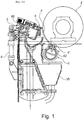
- fig. 1 there is schematically shown a side view of a prior art applicator arrangement.
- fig 2 there is shown a corresponding side view of an applicator arrangement according to the invention, wherein the same reference signs have been used for corresponding parts/elements.
- the arrangement according to the invention seen in fig. 2 occupies a drastically reduced space compared to a prior art arrangement thanks to its beneficial design, as will be explained more in detail below.
- the applicator arrangement 1 comprises a base support arrangement 8, 9, a supply unit 6 for supply of coating liquid/slurry 4, an applicator device 5 and a metering device 7.
- Said supply unit 6 comprises a distribution pipe 62 which forms a support for the applicator device 5 and metering device 7 in that at least one of said applicator device 5 and/or metering device 7 is directly or indirectly attached to said distribution pipe 62 so that, upon operation of the coating machine, at least 50% of the forces from the applicator device 5 and/or metering device 7 are received by the body of the distribution pipe 62.
- the distribution pipe 62 is supported by a support body 3 by means of a bearing arrangement 31 arranged to enable axial expansion and contraction of said distribution pipe 62.
- the support body 3 is mounted on a holding bracket comprising a pivot arm 8 which is pivotally arranged about a pivot axis 80, of a pivot axis 81, whereby said supply unit 6 may be moved towards or away from the backing roll 2.
- a cylinder 9 is arranged to make the pivot arm 8 movable. Together said pivot arm 8 and said cylinder 9 form said base support arrangement 8, 9.
- the cylinder 9 may be affixed in many different ways.
- the pivot arm 8 is arranged to enable pivoting between an active and inactive position of the applicator arrangement 1, and the active pivot axis 80 of said pivoting arm 8 is positioned within an area defined by the vertical tangents of the roll onto which the applicator arrangement 1 is fixed. Thanks to arranging the pivot axis 80 of the pivot arm 8 in a region preferably underneath the roll 2, the lever arrangement and the whole movable unit becomes less space consuming.
- a backing roll 2 is supporting a running web W at its backside.
- the length of the backing roll 2 preferably at least corresponds to the width of the running web W, preferably longer than the length of said running web W.
- Applied coating which is not retained on the web can be collected in a coating pan arrangement 35 and recirculated e.g. via an outlet pipe 36.
- figs. 3A-B the coating machine is shown from the right hand side, including a supply unit 6 as the one shown in fig. 2 , for direct application of a coating medium onto a running web W.
- Fig. 3A shows an end portion of a coating machine equipped with a coating pan arrangement 35 and an outlet pipe 36, whereas in fig. 3B there is displayed bearings 31 arranged between the base support arrangement 3 and the supply unit 6.
- the supply unit 6 comprises a distribution pipe 62 through which coating medium 4 is supplied and distributed, wherein coating medium is distributed from the pipe 62 to e.g. a web W via an applicator device 5 comprising nozzle lips 54, 56 (see also fig. 4 ) forming the gap 55 for outlet of the coating medium 4.
- a support body 3, that supports the distribution pipe 62, forms a fixed stable structure together with distribution pipe 62 implying that there is no need of a temperature control arrangement to eliminate undesired tensions due to temperature changes (which can otherwise lead to bending uneven coating).
- the support structure 3 may not be eliminated by making the distribution pipe 62 "self-supportive" due to the extremely expensive material thereof, which is needed due to the extreme demands, e.g. depending on the desire to minimize fall off of coating ejected from the nozzle gap 55, which is achieved by having the coating 4 supplied at high pressure.
- the support body may be made in any suitable material/form that fulfills the desired need of providing stabile support, e.g. a standard low alloy steel tubing, which facilitates low cost production.
- Low alloy steel may be defined as a steel having a total of alloying elements, e.g. Ni, Cr and Mb, below 10 %, preferably below 8 %, and more preferred below 5 %.
- the distribution pipe 62 is slidable arranged in relation to the support structure 3, e.g. by providing a support base 30 with a bearing 31, which bearing 31 is arranged with a first low friction interface 310 arranged on the support base 30 and a second, mating, low friction interface 311 on the bottom part of the supply tube 62, to allow the distribution pipe 62 to freely slide due to heat expansion/contraction, thereby in an easy, cost-efficient and safe way safeguard a tension-free supply tube 62, i.e. eliminating the need of a cooling arrangement and eliminating a complex support structure 3.
- an elongated metering device 7, also referred to as "metering element”, is attached to said supply unit 6, wherein the length of the metering element 7 preferably corresponds at least to the width of the running web W.
- the distribution pipe 62 forms a support for the metering element 7, and the metering element 7 is attached to the supply unit 6 directly or indirectly.
- the metering element 7 is attached to, and held by a part of the applicator device 5, which in its turn is fixed onto the distribution pipe 62.
- the metering element 7 will be positioned very close to the gap 55 (see fig. 4 ) defined by the applicator device 5 and formed by the nozzle lips 54, 56 through which the coating medium/slurry 4 is supplied from the pipe 62, leading to that both the coating and the metering of excessive slurry can be performed by means of one integrated unit (i.e. the applicator device 5 and the metering element 7), whereby the beneficial compactness of the applicator arrangement can be achieved.
- Said applicator device 5 and/or metering element 7 are attached to the supply unit 6 directly or indirectly, meaning that at least a major portion of the forces created upon the metering element 7 being brought into contact with the underlying running surface are transmitted to and spread within the body of the distribution pipe 62. This leads to improved ability of withstanding applied stress and thereby also to an elongated life time of the equipment.
- Fig. 4 shows a cross sectional transversal view of a first embodiment of a supply unit 6 according to the invention.
- the supply unit 6 comprises a distribution pipe 62, preferably made of metal, and which has an interior cavity 60.
- Said pipe 62 extends parallelly along the roll 2, and continues further on at least one side where the inflow is arranged.
- the coating medium 4 is supplied into the interior cavity 60 of the pipe 62 from one (or both) end of said pipe 62 and flows through a plurality of radial through-holes 61 in the wall of the distribution pipe 62.
- the through-holes 61 are positioned as rows one of through-holes in 61 the axial direction of the distribution pipe 62 leading the medium 4 from the interior cavity 60 into a equalization chamber 53, on the outside of the tube 62.
- Said equalization chamber 53 is delimited on one side by an essentially solid element forming a fixed nozzle lip 54, which is firmly and securely mounted onto the distribution pipe 62 by screws 542.
- the chamber 53 is delimited by a holding body 56. Together the fixed nozzle lip 54 and the holding body 56 form a gap 55 where through coating medium 4 is supplied.
- said fixed nozzle lip 54, holding body 56, equalization chamber 53 and gap 55 define the applicator device 5.
- a coating medium 4 is applied through the applicator device 5 when supplied from the pipe 62 onto an underlying running surface (e.g. a web W or a roll 2).
- the holding body 56 is provided with a foot 59 that fits into a matching groove 63 at the surface of the distribution pipe 62.
- the holding body 56 is firmly fixated onto the distribution pipe 62 by means of a flexible pressure tube 57. This arrangement provides a way of quickly exchanging said holding body 56, which is advantageous since such exchanging often needs to be done quite frequently, and a swift changing of parts means reduced downtime.
- an interconnecting member (not shown) fixedly arranged on the pipe 62 which in its turn provides a fastening location for said foot 59.
- Such an interconnecting member may be attached onto the pipe 62 for instance by means of screwing, thereby replacing the need for producing said groove 63.
- the coating medium 4 leaves the equalization chamber 53 through a gap 55 and is applied on the surface of a web W or a transfer roll or a gravure roll 22 (as will later be described).
- the nozzle lips 54, 56 form the gap 55 for outlet of the coating medium.
- a flexible pressure member 561 and a hinge portion 560 the size of the gap 55 may be continuously controlled.
- the holding body 56 is made in one piece and consists of an elastic material which leads to that it can be made to flex about the hinge portion 560 towards or away from an underlying surface, for instance by means of said flexible pressure member 561.
- the holding body 56 is provided with a metering element 7 (see WO 2007/061378 where the use of the metering element 7 is described) arranged on the upper portion of said holding body 56.
- Said metering element 7 comprises a circular body which is pivotally arranged about its length axis.
- the metering element 7 is further provided with a ridge-formed metering portion 70 having a first meeting side 71, said side 71 being continuously curved, and a rear side 73 comprising an upright edge thereby forming an edge 72 between the meeting side 71 and the rear side 73.
- the embodiment shown in fig. 4 includes a cooling arrangement, wherein the circumferential area of the distribution pipe 62 is surrounded by a plate 662, which is provided with a drop edge 666. Said plate 662 extends approximately 270 about the periphery of the distribution pipe 62.
- a spacing 663 is arranged between the plate 662 and the distribution pipe 62 and its extension about the periphery of the distribution pipe 62 corresponds substantially with the extension of the plate 662.
- This spacing may be filled with cooling medium, e.g. cooling water.
- each end of said spacing 663 is provided with a tightening material 65, 66.
- FIG. 5 there is shown a perspective of a coating machine including a supply unit 6 according to the invention for indirect application of a coating medium onto a running web W.
- a transfer roll 21 is placed on each side of the running web W.
- the bearing 31 between the support structure 3 and the distribution pipe 62 said bearing 31 comprising a first low friction interface 310 arranged on the support base 30 and a second, mating, low friction interface 311 on the bottom part of the supply tube 62.
- said distribution pipe 62 is slidable arranged in relation to the support structure 3.
- the support structure 3 is delimited by means of a body 32 (e.g. an inner tube member) positioned within the interior of the support base 30 to form a space 38 between the inner surface of the support base tube 30 and the exterior surface of the inner body 32, said space 38 being arranged to provide for a flow of tempering liquid for acquiring an even temperature along and around the support base 30.
- said delimited space 38 may be provided with sealing members 37 enabling spiraling circulation within the support body 3 which further contributes to said acquiring of an even temperature without any temperature gradients.
- the sealing members 37 may for instance form a structure between the inner surface of the support base tube 30 and the exterior surface of the inner body 32 arranged to guide the passing flow of tempering liquid through the delimited space 38.
- such structure may be in the form of a helix extending along the support base 30 surface arranged to enable said spiraling circulation.
- the sealing members 37 comprise O-ring members arranged around the circumferential inner surface of the support base tube 30 to form said helix surface structure leading to that a passing flow of tempering medium will be urged to circulate around the tube 30 while passing through the support unit 3.
- a gravure roll 22 is positioned along the transfer roll 21 so that the longitudinal axes of the rolls, respectively, are substantially parallel to each other.
- the length of the gravure roll 22 corresponds to the length of the transfer roll 21, said length of the rolls being at least as long as the width of the running web W, preferably longer than the length of said running web W.
- Fig. 7 depicts an additional embodiment of a supply unit 6 of the present invention where the pressure tube 561 is replaced by a plurality of distributed pressure bellows 569. Said pressure bellows 569 are positioned with appreciate spacing so as to apply either a uniform pressure on the envelope surface of the holding body 56 or a pressure that varies along the envelope surface, which may be desired in some situations.
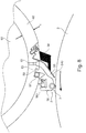
- Fig. 8 shows a cross sectional transversal view of a preferred embodiment of a supply unit 6 according to the invention, wherein no cooling arrangement is used.
- an applicator device 5 comprising a fixed nozzle lip 54 and a holding body 56 is attached onto the supply unit 6 in the form of a distribution pipe 62.
- Coating medium 4 is arranged to flow through the distribution pipe 62 and via through-holes 61 in the wall of the distribution pipe 62 for further passage between the fixed nozzle lip 54 and holding body 56 of the applicator device 5 and is thereafter supplied onto the running roll 2 via the gap 55.
- the fixed nozzle lip 54 is co-acting with a resilient blade 540 which is attached onto the distribution pipe 62 next to the fixed nozzle lip 54 at the side of the fixed nozzle lip 54 which faces the through passage for coating medium and the gap 55.
- the thickness t of the distribution pipe 62 wall is even around the pipe circumference, preferably between 5 - 30 mm, even more preferred between 10 - 20 mm.
- the wall thickness t is at least large enough for allowing fastening of said holding body 56 which, as previously described, may be attached onto the supply unit 6 by means of a groove 63 at the surface of the distribution pipe 62.
- a fine plate-like mineral typically clay or particulate calcium carbonate
- coloring agents typically titanium dioxide for a white sheet
- a binder which may be of the organic type or of a synthetic composition.
- Another type of coating medium may be an aqueous solution comprising e.g. starch used in sizing applications.
- said holding body 56 may be attached onto the supply unit 6 via an interconnecting member (not shown) that may be attached onto the distribution pipe 62 surface, e.g. by means of screwing.
- interconnecting member not shown
- many other forms (than tubular) and material (than low alloy steel) may be used to design the support body 3, e.g. in the form of traditional beams, e.g. I-beam, etc. and by using other materials, e.g. plain carbon steel (with or without lining), polymeric materials (e.g. with reinforcement), concrete (e.g. with reinforcement), etc.
Landscapes
- Coating Apparatus (AREA)
- Application Of Or Painting With Fluid Materials (AREA)
Abstract
Description
- The present invention relates to an applicator arrangement including a distribution pipe and is a divisional from
EP-A-12752932.9 - The so called blade coating technique is a prior art method for the coating of running webs. This technique that exists in lots of varieties is based on the principle that a coating medium (colour, starch for example) surplus is supplied at a surplus to the web at a position prior to a final dosing metering means. Said final dosing and metering means may be composed of structure combined with thin flexible blades, rigid blades or rods that, similar to puttying, doses out and applies the amount of coating medium, see for example
WO 2007/061378 which is herewith incorporated by reference. The dosing and coating means are comprised in an applicator arrangement, which for instance comprises means for handling the surplus of the coating medium, which is returned for circulation and reuse by the arrangement. Prior art applicator arrangements present several disadvantages, e.g. having a bulky and relatively complex structure. - In
US 2001/0008118 a coating device for directly or indirectly applying a coating medium onto a running paper- or board web is shown. The device includes nozzle lips of which at least one is being formed by a blade element. By applying an elastic nozzle lip, the nozzle gap can be enlarged. The coating device includes a mechanism for adjusting the height of the nozzle gap. A disadvantage with this design is that it is designed as a separate unit implying difficulties in achieving a compact design of the whole application arrangement. - A related problem within the field of dosing and coating arrangements is that the coating medium mostly has to be supplied at a temperature that is different (normally higher) compared to ambient temperature, in combination with the fact that the total applicator arrangement is relatively large, i.e. extends over the cross machine width. As consequence there may result temperature gradients causing bending of the applicator arrangement, which may result in coat weight variations. In many applicator arrangements, e.g.
US 5772766 , there are no arrangement to counter act this negative effect. According to some prior art this problem is commonly handled by costly and bulky temperature control structures, e.g. as shown inEP 0 931 878 . This prior art document describes a fountain coating applicator presenting an alternative manner of handling the latter problem, i.e. the tendency of heated coating to cause a temperature gradient is counteracted by cantilevering the applicator head on arms from a support beam through which a temperature-controlling fluid is circulated. - It is an object of the present invention to overcome or at least minimize at least one of the drawbacks and disadvantages described above, which is achieved by means of an arrangement and method according to the appended claims.
- Thanks to a solution according to the invention there is provided an applicator arrangement which is very compact and does not require as much space as prior art technique does. Investment costs may be smaller and the accessibility of the arrangement may make maintenance and reparations easier and cheaper. According to a preferred embodiment this achieved by an applicator arrangement wherein means for distribution of coating medium and scraping off a surplus of coating medium are in the form of integrated units.
- According to one aspect of the invention the applicator arrangement according to the invention comprises a supply unit for supply of coating liquid/slurry, an applicator device and a metering device, wherein said supply unit forms a support for both of said applicator device and metering device, and wherein both of said applicator device and/or metering device are directly or indirectly attached to said supply unit. Preferably said supply unit comprises a distribution pipe which in its turn is supported by a support body by means of a bearing arrangement arranged to enable axial expansion and contraction of said distribution pipe.
- It is to be understood that said supply unit forms a support body for said applicator device and/or metering device in the sense that it receives forces transmitted from said applicator device and/or metering device upon operation. This means according to the invention at least a majority of the forces applied from the applicator device and/or metering device upon use are arranged to be spread to and distributed within the body which constitutes said supply unit.
- Positive effects of synergy are obtained thanks to an applicator arrangement according to the invention, among others that a shorter flow passage is acquired between the supply unit and the mouth of the applicator device, i.e. in addition to the compactness of the arrangement also the radially shorter flow passage contributes to acquire an even flow of the coating medium.
- According to still another aspect of the invention said supply unit is in the form of a distribution pipe or tube, preferably a circular tube of a metallic non welded design, more preferred a standard tube, which provides a much more cost-efficient pressure vessel than traditionally used supply vessels.
- According to still another aspect of the invention that said distribution pipe is supported by a support body by means of a bearing arrangement arranged to enable axial expansion and contraction of said distribution pipe, wherein preferably said support body is in the form of a tube, more preferred of a low alloy steel material.
- According to still another aspect of the invention it relates to a holding body for an applicator arrangement according to
claim 1, wherein said metering element is attached to, and held by said holding body, which also forms one of said nozzle lips of said applicator device, wherein said holding body that holds the metering device, is arranged to be attached to said distribution pipe, wherein preferably said holding body is provided with a foot arranged to fit into a matching groove supported by the distribution pipe, which provides for quick and reliable exchange of metering device. - According to still another aspect of the invention that the size of said gap is arranged to be continuously controlled by means of a flexible pressure member and a hinge portion of said holding body, which provides for precise and reliable gap control.
- According to still another aspect of the invention said pressure member is in the form of a plurality of distributed pressure bellows.
- According to still another aspect of the invention it relates to a method for exchanging a metering device in a coating machine, in an efficient manner.
- According to another aspect of the invention said supply unit is supported by a support body, wherein preferably said support body is made in a much cheaper material than the supply unit, e.g. a low alloy steel. Hereby manufacturing costs for an applicator arrangement according to the invention can be cut.
- According to another aspect of the invention said supply unit is supported on the support body by means of bearing arrangement arranged to enable axial expansion and contraction of said supply unit, thereby eliminating the need of sophisticated tempering means to avoid bending of the body.
- According to another aspect of the invention said supply unit is arranged to function without the use of any cooling housing, that otherwise would participate in the expansions/contractions of the supply unit, which makes the arrangement significantly less expensive and more easy to control.
- According to yet another aspect of the invention, and thanks to the compact and space-saving arrangement according to the invention two applicator arrangements may be positioned at the periphery of one and the same roll, directly after each other. As a result of this a very well-covering coating of the surface of the running web may be achieved.
- The foregoing aspects and many of the attendant advantages of this invention will become more readily appreciated as the same become better understood by reference to the following detailed description, when taken in conjunction with the accompanying drawings, wherein:
- Fig. 1
- shows a side view of a generally known prior art applicator arrangement,
- Fig. 2
- shows a side view of a preferred embodiment of an applicator arrangement according to the invention, in use for one sided application,
- Fig. 3A-B
- show an applicator arrangement according to one embodiment from the right hand side of the applicator arrangement in
fig. 2 , - Fig. 4
- shows a cross sectional transversal view of an embodiment of an applicator arrangement according to the invention, further provided with a cooling arrangement,
- Fig. 5
- shows a side view of an applicator arrangement as shown in
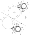
figs. 2 and3 , in use for double sided application, by means of transfer rolls, - Fig. 6
- shows a side view of an applicator arrangement as shown in
figs. 2 and3 , in use for double sided application, by means of gravure rolls, - Fig. 7
- shows a cross sectional transversal view of a second embodiment of an applicator arrangement according to the invention, and
- Fig. 8
- shows a cross sectional transversal view of a third embodiment of an applicator arrangement according to the invention.
- The following detailed description, and the examples contained therein, are provided for the purpose of describing and illustrating certain embodiments of the invention only and are not intended to limit the scope of the invention in any way.
- In
fig. 1 there is schematically shown a side view of a prior art applicator arrangement. Infig 2 there is shown a corresponding side view of an applicator arrangement according to the invention, wherein the same reference signs have been used for corresponding parts/elements. As can be seen the arrangement according to the invention seen infig. 2 occupies a drastically reduced space compared to a prior art arrangement thanks to its beneficial design, as will be explained more in detail below. - The applicator arrangement will now be described referring mainly to
figs. 2 - 6 . According to one embodiment theapplicator arrangement 1 according to the invention comprises abase support arrangement supply unit 6 for supply of coating liquid/slurry 4, anapplicator device 5 and ametering device 7. Saidsupply unit 6 comprises adistribution pipe 62 which forms a support for theapplicator device 5 andmetering device 7 in that at least one of saidapplicator device 5 and/ormetering device 7 is directly or indirectly attached to saiddistribution pipe 62 so that, upon operation of the coating machine, at least 50% of the forces from theapplicator device 5 and/ormetering device 7 are received by the body of thedistribution pipe 62. - Further, the
distribution pipe 62 is supported by asupport body 3 by means of abearing arrangement 31 arranged to enable axial expansion and contraction of saiddistribution pipe 62. Thesupport body 3 is mounted on a holding bracket comprising apivot arm 8 which is pivotally arranged about apivot axis 80, of apivot axis 81, whereby saidsupply unit 6 may be moved towards or away from thebacking roll 2. Acylinder 9 is arranged to make thepivot arm 8 movable. Together saidpivot arm 8 and saidcylinder 9 form saidbase support arrangement cylinder 9 may be affixed in many different ways. Thepivot arm 8 is arranged to enable pivoting between an active and inactive position of theapplicator arrangement 1, and theactive pivot axis 80 of said pivotingarm 8 is positioned within an area defined by the vertical tangents of the roll onto which theapplicator arrangement 1 is fixed. Thanks to arranging thepivot axis 80 of thepivot arm 8 in a region preferably underneath theroll 2, the lever arrangement and the whole movable unit becomes less space consuming. - In the example of
fig. 2 abacking roll 2 is supporting a running web W at its backside. The length of thebacking roll 2 preferably at least corresponds to the width of the running web W, preferably longer than the length of said running web W. Adjacent thebacking roll 2 there is arranged ansupply unit 6 and anapplicator device 5 according to the invention. Saidsupply unit 6, which extends the full width of thebacking roll 2 in the cross machine direction, provides via a supply anddistribution pipe 62 the running web W with afilm 4 of a coating medium, as will be later described in more detail. Applied coating which is not retained on the web can be collected in acoating pan arrangement 35 and recirculated e.g. via anoutlet pipe 36. - In
figs. 3A-B the coating machine is shown from the right hand side, including asupply unit 6 as the one shown infig. 2 , for direct application of a coating medium onto a running web W.Fig. 3A shows an end portion of a coating machine equipped with acoating pan arrangement 35 and anoutlet pipe 36, whereas infig. 3B there is displayedbearings 31 arranged between thebase support arrangement 3 and thesupply unit 6. Thesupply unit 6 comprises adistribution pipe 62 through whichcoating medium 4 is supplied and distributed, wherein coating medium is distributed from thepipe 62 to e.g. a web W via anapplicator device 5 comprisingnozzle lips 54, 56 (see alsofig. 4 ) forming thegap 55 for outlet of thecoating medium 4. - A
support body 3, that supports thedistribution pipe 62, forms a fixed stable structure together withdistribution pipe 62 implying that there is no need of a temperature control arrangement to eliminate undesired tensions due to temperature changes (which can otherwise lead to bending = uneven coating). Thesupport structure 3 may not be eliminated by making thedistribution pipe 62 "self-supportive" due to the extremely expensive material thereof, which is needed due to the extreme demands, e.g. depending on the desire to minimize fall off of coating ejected from thenozzle gap 55, which is achieved by having thecoating 4 supplied at high pressure. However, thanks to the novel concept the support body may be made in any suitable material/form that fulfills the desired need of providing stabile support, e.g. a standard low alloy steel tubing, which facilitates low cost production. Low alloy steel may be defined as a steel having a total of alloying elements, e.g. Ni, Cr and Mb, below 10 %, preferably below 8 %, and more preferred below 5 %. - According to one embodiment, the
distribution pipe 62 is slidable arranged in relation to thesupport structure 3, e.g. by providing asupport base 30 with abearing 31, which bearing 31 is arranged with a firstlow friction interface 310 arranged on thesupport base 30 and a second, mating,low friction interface 311 on the bottom part of thesupply tube 62, to allow thedistribution pipe 62 to freely slide due to heat expansion/contraction, thereby in an easy, cost-efficient and safe way safeguard a tension-free supply tube 62, i.e. eliminating the need of a cooling arrangement and eliminating acomplex support structure 3. - As is illustrated in
fig. 3A anelongated metering device 7, also referred to as "metering element", is attached to saidsupply unit 6, wherein the length of themetering element 7 preferably corresponds at least to the width of the running web W. The structure of saidmetering element 7 as well its function will later be described in more detail (see for instancefig. 4 andfigs. 7 - 8 ). Preferably thedistribution pipe 62 forms a support for themetering element 7, and themetering element 7 is attached to thesupply unit 6 directly or indirectly. In one embodiment themetering element 7 is attached to, and held by a part of theapplicator device 5, which in its turn is fixed onto thedistribution pipe 62. Hereby themetering element 7 will be positioned very close to the gap 55 (seefig. 4 ) defined by theapplicator device 5 and formed by thenozzle lips slurry 4 is supplied from thepipe 62, leading to that both the coating and the metering of excessive slurry can be performed by means of one integrated unit (i.e. theapplicator device 5 and the metering element 7), whereby the beneficial compactness of the applicator arrangement can be achieved. - Said
applicator device 5 and/ormetering element 7 are attached to thesupply unit 6 directly or indirectly, meaning that at least a major portion of the forces created upon themetering element 7 being brought into contact with the underlying running surface are transmitted to and spread within the body of thedistribution pipe 62. This leads to improved ability of withstanding applied stress and thereby also to an elongated life time of the equipment. -
Fig. 4 shows a cross sectional transversal view of a first embodiment of asupply unit 6 according to the invention. Thesupply unit 6 comprises adistribution pipe 62, preferably made of metal, and which has aninterior cavity 60. Saidpipe 62 extends parallelly along theroll 2, and continues further on at least one side where the inflow is arranged. Thecoating medium 4 is supplied into theinterior cavity 60 of thepipe 62 from one (or both) end of saidpipe 62 and flows through a plurality of radial through-holes 61 in the wall of thedistribution pipe 62. The through-holes 61 are positioned as rows one of through-holes in 61 the axial direction of thedistribution pipe 62 leading the medium 4 from theinterior cavity 60 into aequalization chamber 53, on the outside of thetube 62. Saidequalization chamber 53 is delimited on one side by an essentially solid element forming a fixednozzle lip 54, which is firmly and securely mounted onto thedistribution pipe 62 byscrews 542. On the other side thechamber 53 is delimited by a holdingbody 56. Together the fixednozzle lip 54 and the holdingbody 56 form agap 55 where throughcoating medium 4 is supplied. In the present exemplifying description said fixednozzle lip 54, holdingbody 56,equalization chamber 53 andgap 55 define theapplicator device 5. Acoating medium 4 is applied through theapplicator device 5 when supplied from thepipe 62 onto an underlying running surface (e.g. a web W or a roll 2). The holdingbody 56 is provided with afoot 59 that fits into a matchinggroove 63 at the surface of thedistribution pipe 62. The holdingbody 56 is firmly fixated onto thedistribution pipe 62 by means of aflexible pressure tube 57. This arrangement provides a way of quickly exchanging said holdingbody 56, which is advantageous since such exchanging often needs to be done quite frequently, and a swift changing of parts means reduced downtime. - Other ways of attaching the holding
body 56 are also possible, for instance by means of an interconnecting member (not shown) fixedly arranged on thepipe 62 which in its turn provides a fastening location for saidfoot 59. Such an interconnecting member may be attached onto thepipe 62 for instance by means of screwing, thereby replacing the need for producing saidgroove 63. - The
coating medium 4 leaves theequalization chamber 53 through agap 55 and is applied on the surface of a web W or a transfer roll or a gravure roll 22 (as will later be described). Thenozzle lips gap 55 for outlet of the coating medium. By means of aflexible pressure member 561 and ahinge portion 560 the size of thegap 55 may be continuously controlled. According to one embodiment the holdingbody 56 is made in one piece and consists of an elastic material which leads to that it can be made to flex about thehinge portion 560 towards or away from an underlying surface, for instance by means of saidflexible pressure member 561. - The holding
body 56 is provided with a metering element 7 (seeWO 2007/061378 where the use of themetering element 7 is described) arranged on the upper portion of said holdingbody 56. Saidmetering element 7 comprises a circular body which is pivotally arranged about its length axis. Themetering element 7 is further provided with a ridge-formedmetering portion 70 having afirst meeting side 71, saidside 71 being continuously curved, and arear side 73 comprising an upright edge thereby forming anedge 72 between themeeting side 71 and therear side 73. - In an arrangement using this
metering element 7 the advantage is obtained that when no contact is wanted between themetering element 7 and the web or roll themetering element 7 is turned so that no contact longer exists between themetering portion 70 and the web orroll 1. This means that thesupply unit 6 as a whole may remain in its position. - The embodiment shown in
fig. 4 includes a cooling arrangement, wherein the circumferential area of thedistribution pipe 62 is surrounded by aplate 662, which is provided with adrop edge 666. Saidplate 662 extends approximately 270about the periphery of the
distribution pipe 62. A spacing 663 is arranged between theplate 662 and thedistribution pipe 62 and its extension about the periphery of thedistribution pipe 62 corresponds substantially with the extension of theplate 662. This spacing may be filled with cooling medium, e.g. cooling water. To avoid cooling medium to leak out from the spacing 663 each end of saidspacing 663 is provided with a tighteningmaterial - In
fig. 5 there is shown a perspective of a coating machine including asupply unit 6 according to the invention for indirect application of a coating medium onto a running web W. Atransfer roll 21 is placed on each side of the running web W. Adjacent to thetransfer roll 21 there is arranged saidsupply unit 6, providing thetransfer roll 21 with afilm 4 of coating medium which film is applied onto the running web W in a so called indirect application procedure of acoating medium 4 onto the running web W. Herein is also illustrated thebearing 31 between thesupport structure 3 and thedistribution pipe 62, saidbearing 31 comprising a firstlow friction interface 310 arranged on thesupport base 30 and a second, mating,low friction interface 311 on the bottom part of thesupply tube 62. By means of thebearing 31 saiddistribution pipe 62 is slidable arranged in relation to thesupport structure 3. - The
support structure 3 is delimited by means of a body 32 (e.g. an inner tube member) positioned within the interior of thesupport base 30 to form aspace 38 between the inner surface of thesupport base tube 30 and the exterior surface of theinner body 32, saidspace 38 being arranged to provide for a flow of tempering liquid for acquiring an even temperature along and around thesupport base 30. In one embodiment saiddelimited space 38 may be provided with sealingmembers 37 enabling spiraling circulation within thesupport body 3 which further contributes to said acquiring of an even temperature without any temperature gradients. The sealingmembers 37 may for instance form a structure between the inner surface of thesupport base tube 30 and the exterior surface of theinner body 32 arranged to guide the passing flow of tempering liquid through the delimitedspace 38. For example such structure may be in the form of a helix extending along thesupport base 30 surface arranged to enable said spiraling circulation. According to one embodiment the sealingmembers 37 comprise O-ring members arranged around the circumferential inner surface of thesupport base tube 30 to form said helix surface structure leading to that a passing flow of tempering medium will be urged to circulate around thetube 30 while passing through thesupport unit 3. - Also in
fig. 6 there is shown an example of an indirect application procedure using an applicator arrangement according to the present invention. Herein agravure roll 22 is positioned along thetransfer roll 21 so that the longitudinal axes of the rolls, respectively, are substantially parallel to each other. The length of thegravure roll 22 corresponds to the length of thetransfer roll 21, said length of the rolls being at least as long as the width of the running web W, preferably longer than the length of said running web W. Adjacent thegravure roll 22 there is arranged saidsupply unit 6. Saidsupply unit 6, which extends the full width of thegravure roll 22 in the cross machine direction, provides thegravure roll 22 with afilm 4 of a coating medium, saidfilm 4 being applied to thetransfer roll 21 and further, finally, to the running web W. -
Fig. 7 depicts an additional embodiment of asupply unit 6 of the present invention where thepressure tube 561 is replaced by a plurality of distributed pressure bellows 569. Said pressure bellows 569 are positioned with appreciate spacing so as to apply either a uniform pressure on the envelope surface of the holdingbody 56 or a pressure that varies along the envelope surface, which may be desired in some situations. -
Fig. 8 shows a cross sectional transversal view of a preferred embodiment of asupply unit 6 according to the invention, wherein no cooling arrangement is used. Similarly to previously described embodiments anapplicator device 5 comprising a fixednozzle lip 54 and a holdingbody 56 is attached onto thesupply unit 6 in the form of adistribution pipe 62.Coating medium 4 is arranged to flow through thedistribution pipe 62 and via through-holes 61 in the wall of thedistribution pipe 62 for further passage between the fixednozzle lip 54 and holdingbody 56 of theapplicator device 5 and is thereafter supplied onto the runningroll 2 via thegap 55. - In the embodiment illustrated in
fig. 8 the fixednozzle lip 54 is co-acting with aresilient blade 540 which is attached onto thedistribution pipe 62 next to the fixednozzle lip 54 at the side of the fixednozzle lip 54 which faces the through passage for coating medium and thegap 55. - Preferably the thickness t of the
distribution pipe 62 wall is even around the pipe circumference, preferably between 5 - 30 mm, even more preferred between 10 - 20 mm. In a preferred embodiment the wall thickness t is at least large enough for allowing fastening of said holdingbody 56 which, as previously described, may be attached onto thesupply unit 6 by means of agroove 63 at the surface of thedistribution pipe 62. - Mixture of a fine plate-like mineral, typically clay or particulate calcium carbonate; coloring agents, typically titanium dioxide for a white sheet; and a binder which may be of the organic type or of a synthetic composition. Another type of coating medium may be an aqueous solution comprising e.g. starch used in sizing applications.
- As will be understood by those skilled in the present field of art, numerous changes and modifications may be made to the above described and other embodiments of the present invention, without departing from its scope as defined in the appending claims. For example a metering rod can be used instead of the
metering element 7. - It is understood that the objects of the present invention set forth above, among those made apparent by the detailed description, shall be interpreted as illustrative and not in a limiting sense. Within the scope of the following claims the set-up of various alterations of the present invention may be possible, for instance that said holding
body 56 may be attached onto thesupply unit 6 via an interconnecting member (not shown) that may be attached onto thedistribution pipe 62 surface, e.g. by means of screwing. Further it is evident for the skilled person that many other forms (than tubular) and material (than low alloy steel) may be used to design thesupport body 3, e.g. in the form of traditional beams, e.g. I-beam, etc. and by using other materials, e.g. plain carbon steel (with or without lining), polymeric materials (e.g. with reinforcement), concrete (e.g. with reinforcement), etc.
Claims (12)
- An applicator arrangement, comprising a supply unit (6) for supply of coating liquid/slurry, an applicator device (5) and a metering device (7), characterized in that said supply unit (6) forms a support for both said applicator device (5) and said metering device (7), wherein said applicator device (5) and/metering device is directly or indirectly attached to said supply unit (6), wherein said supply unit (6) comprises a distribution pipe (62) comprising a row of through-holes (61) leading into an equalization chamber (53) of said applicator device (5), said applicator device (5) comprising nozzle lips (54, 56) forming a gap (55) for outlet of the coating medium (4).
- Applicator arrangement according to claims 1, characterized in that said distribution pipe (62) is in the form of a tube (62), preferably of a circular tube of a metallic non welded design, more preferred a standard tube.
- Applicator arrangement according to claim 1 or 2, characterized in that said distribution pipe (62) is supported by a support body (3) by means of a bearing arrangement (31) arranged to enable axial expansion and contraction of said distribution pipe (62).
- Applicator arrangement according to any of claim 5, characterized in that said support body (3) is in the form of a tube, preferably of a low alloy steel material.
- Holding body (56) for an applicator arrangement according to claim 1, characterized in that said metering element (7) is attached to, and held by said holding body (56), which also forms one of said nozzle lips of said applicator device (5), and that said holding body (56) that holds the metering device (7), is arranged to be attached to said distribution pipe (62).
- Holding body (56) according to claim 5, characterized in that the size of said gap (55) is arranged to be continuously controlled by means of a flexible pressure member (561) and a hinge portion (560) of said holding body (56).
- Holding body (56) according to claim 6, characterized in that said pressure member (561) is in the form of a plurality of distributed pressure bellows (569).
- Holding body (56) according to claim 6, characterized in that said pressure member (561) is in the form of a pressure tube.
- Holding body (56) according to claim 5, characterized in that said holding body (56) is provided with a foot (59) arranged to fit into a matching groove (63) supported by of the distribution pipe (62).
- Holding body (56) according to claim 9, characterized in that said holding body (56) is arranged to be firmly fixated onto the distribution pipe (62) by means of a flexible pressure tube (57).
- A method for exchanging a metering device (7) in a coating machine, said coating machine comprising an applicator arrangement according to claim 1 and a holding body according to claim 5, comprising the steps:- Detaching a used holding body (56) from the supply unit (6),- And installing another holding (56) having a new metering device (7) arranged therein, onto the supply unit (6).
- A method according to claim 11, comprising the additional steps of using a pressure tube (57) I connection with detachment and installation, respectively, of said holding body (56).
Priority Applications (1)
| Application Number | Priority Date | Filing Date | Title |
|---|---|---|---|
| EP25191589.8A EP4613386A3 (en) | 2011-03-03 | 2012-03-02 | Device for dosing and coating |
Applications Claiming Priority (3)
| Application Number | Priority Date | Filing Date | Title |
|---|---|---|---|
| SE1150194A SE535994C2 (en) | 2011-03-03 | 2011-03-03 | Method and apparatus for dosing and coating |
| EP12752932.9A EP2680980B1 (en) | 2011-03-03 | 2012-03-02 | Method and device for dosing and coating |
| PCT/SE2012/050243 WO2012118438A1 (en) | 2011-03-03 | 2012-03-02 | Method and device for dosing and coating |
Related Parent Applications (2)
| Application Number | Title | Priority Date | Filing Date |
|---|---|---|---|
| EP12752932.9A Division EP2680980B1 (en) | 2011-03-03 | 2012-03-02 | Method and device for dosing and coating |
| EP12752932.9A Division-Into EP2680980B1 (en) | 2011-03-03 | 2012-03-02 | Method and device for dosing and coating |
Related Child Applications (1)
| Application Number | Title | Priority Date | Filing Date |
|---|---|---|---|
| EP25191589.8A Division EP4613386A3 (en) | 2011-03-03 | 2012-03-02 | Device for dosing and coating |
Publications (3)
| Publication Number | Publication Date |
|---|---|
| EP3791965A1 true EP3791965A1 (en) | 2021-03-17 |
| EP3791965C0 EP3791965C0 (en) | 2025-08-06 |
| EP3791965B1 EP3791965B1 (en) | 2025-08-06 |
Family
ID=46758204
Family Applications (3)
| Application Number | Title | Priority Date | Filing Date |
|---|---|---|---|
| EP25191589.8A Pending EP4613386A3 (en) | 2011-03-03 | 2012-03-02 | Device for dosing and coating |
| EP12752932.9A Active EP2680980B1 (en) | 2011-03-03 | 2012-03-02 | Method and device for dosing and coating |
| EP20203577.0A Active EP3791965B1 (en) | 2011-03-03 | 2012-03-02 | Device for dosing and coating |
Family Applications Before (2)
| Application Number | Title | Priority Date | Filing Date |
|---|---|---|---|
| EP25191589.8A Pending EP4613386A3 (en) | 2011-03-03 | 2012-03-02 | Device for dosing and coating |
| EP12752932.9A Active EP2680980B1 (en) | 2011-03-03 | 2012-03-02 | Method and device for dosing and coating |
Country Status (7)
| Country | Link |
|---|---|
| US (1) | US9409205B2 (en) |
| EP (3) | EP4613386A3 (en) |
| CN (2) | CN103501920B (en) |
| ES (2) | ES3043507T3 (en) |
| PL (2) | PL2680980T3 (en) |
| SE (1) | SE535994C2 (en) |
| WO (1) | WO2012118438A1 (en) |
Families Citing this family (7)
| Publication number | Priority date | Publication date | Assignee | Title |
|---|---|---|---|---|
| EP2811070B1 (en) | 2013-06-06 | 2016-04-20 | Valmet Technologies, Inc. | Application unit of a coating or sizing device for applying treatment substance on a fiber web |
| EP3180475B2 (en) † | 2014-08-15 | 2021-11-03 | Voith Patent GmbH | Coating device |
| CN107554038A (en) * | 2017-10-23 | 2018-01-09 | 德清众邦复合材料有限公司 | Special in hot pressing hybrid system rolls binder blanking subsystem |
| JP6975894B2 (en) * | 2018-08-30 | 2021-12-01 | 株式会社豊田自動織機 | Gravure coating equipment and paint coating method |
| DE102018009535A1 (en) * | 2018-12-07 | 2020-06-10 | Andritz Küsters Gmbh | Commissioned work for the direct or indirect application of a coating medium |
| CN111389650B (en) * | 2020-04-10 | 2020-10-20 | 磐安艾肯机械设备有限公司 | Even mopping cylinder of adjustable lacquer painting thickness and need not to dip in lacquer |
| DE102023106579A1 (en) * | 2023-03-16 | 2024-09-19 | Voith Patent Gmbh | Application device and process |
Citations (5)
| Publication number | Priority date | Publication date | Assignee | Title |
|---|---|---|---|---|
| US5772766A (en) | 1994-09-09 | 1998-06-30 | Voith Papiermaschinen Gmbh | Application unit for the direct or indirect application of a liquid or pasty medium onto a moving material web |
| EP0931878A2 (en) | 1998-01-27 | 1999-07-28 | Beloit Technologies, Inc. | Fountain coating applicator |
| US20010008118A1 (en) | 2000-01-14 | 2001-07-19 | Richard Bernert | Coating machine for direct or indirect coating of a material web |
| WO2007061378A1 (en) | 2005-11-28 | 2007-05-31 | Mattssonföretagen I Uddevalla Aktiebolag | Method and device for coating |
| DE102009061033A1 (en) * | 2009-06-08 | 2010-12-09 | Metso Paper, Inc. | Doctor blade apparatus useful in a system for coating a material web such as paper- or cardboard web, comprises a holder produced from a composite material in a continuous primary forming method, a doctor blade bed, and a doctor blade rod |
Family Cites Families (23)
| Publication number | Priority date | Publication date | Assignee | Title |
|---|---|---|---|---|
| US3706508A (en) * | 1971-04-16 | 1972-12-19 | Sean Lingwood | Transpiration cooled turbine blade with metered coolant flow |
| FR2198797B1 (en) * | 1972-09-08 | 1975-01-03 | Vallourec | |
| US4316428A (en) * | 1980-12-01 | 1982-02-23 | S&S Corrugated Paper Machinery Co., Inc. | Fluid metering device |
| DE3417487A1 (en) | 1984-05-11 | 1985-11-21 | J.M. Voith Gmbh, 7920 Heidenheim | DEVICE FOR APPLYING A LIQUID ON A RUNNING TRAIN |
| US4887547A (en) * | 1985-07-31 | 1989-12-19 | Jagenberg Aktiengesellschaft | Apparatus for continuously applying a uniform coating to a material web |
| AT396437B (en) | 1986-10-25 | 1993-09-27 | Voith Gmbh J M | PRE-DOSING DEVICE IN A COATING PLANT |
| US4949667A (en) * | 1988-04-20 | 1990-08-21 | Dainippon Screen Mfg. Co., Ltd. | Roll coating apparatus for forming a film of a high viscosity coating liquid on a surface |
| FI85895C (en) | 1988-11-18 | 1992-06-10 | Valmet Paper Machinery Inc | Method of compensating the bending of a maker and bending-compensated maker |
| DE4141133C1 (en) | 1991-12-13 | 1993-05-27 | J.M. Voith Gmbh, 7920 Heidenheim, De | Support beam for doctor blade bearing on dry cylinder - comprises elongated hollow body having 2 or more convex curved longitudinal walls and composed of composite fibre material e.g. carbon@ fibres |
| DE4239793A1 (en) * | 1992-01-03 | 1993-07-08 | Noelle Gmbh | |
| DE4243518C2 (en) * | 1992-12-22 | 1996-03-28 | Feldmuehle Ag Stora | Devices for applying liquid to both sides of a material web and method for applying a liquid to a material web with these devices |
| FI105167B (en) | 1995-12-28 | 2000-06-30 | Valmet Corp | Application device for applying coatings on a moving surface |
| DE19619249A1 (en) * | 1996-05-13 | 1997-11-20 | Voith Sulzer Papiermasch Gmbh | Applicator for direct or indirect application of a liquid or pasty medium to a running material web |
| DE19620261A1 (en) | 1996-05-20 | 1997-11-27 | Voith Sulzer Papiermasch Gmbh | Applicator for direct or indirect application of a liquid or pasty medium to a running material web |
| DE19649559A1 (en) | 1996-11-29 | 1998-06-04 | Voith Sulzer Papiermasch Gmbh | Device for the direct or indirect application of a liquid or pasty coating medium to a running material web |
| DE19743520B4 (en) * | 1997-10-01 | 2005-12-08 | Voith Paper Patent Gmbh | Squeegee device for a device for applying a liquid to pasty medium on a passing underground |
| JP2002536174A (en) * | 1999-02-11 | 2002-10-29 | アルキャン・インターナショナル・リミテッド | Apparatus and method for controlling coating profile by direct coating method |
| US7220365B2 (en) * | 2001-08-13 | 2007-05-22 | New Qu Energy Ltd. | Devices using a medium having a high heat transfer rate |
| DE10337594B4 (en) * | 2003-08-16 | 2006-03-23 | Siempelkamp Maschinen- Und Anlagenbau Gmbh & Co. Kg | Release agent application means |
| CN101484253B (en) * | 2006-07-05 | 2011-03-09 | 菲奇工程技术有限公司 | Roll support device, roll coating head using the same, roll coater, and coating method |
| DE102008041119A1 (en) | 2008-08-08 | 2010-02-11 | Voith Patent Gmbh | Device for direct or indirect application of a liquid or pasty application medium to a movable material web |
| FI8407U1 (en) | 2009-03-02 | 2009-08-27 | Metso Paper Inc | Roller for a fiber web machine |
| DE102009050917B3 (en) * | 2009-10-23 | 2010-10-07 | Salzgitter Mannesmann Präzisrohr GmbH | Doctor blade of a dosing system for distributing and stripping a fluid or viscous medium on running material web such as paper or cardboard web, where the fluid or viscous medium is applied in excess and is removed by the doctor blade |
-
2011
- 2011-03-03 SE SE1150194A patent/SE535994C2/en unknown
-
2012
- 2012-03-02 ES ES20203577T patent/ES3043507T3/en active Active
- 2012-03-02 CN CN201280020729.4A patent/CN103501920B/en active Active
- 2012-03-02 WO PCT/SE2012/050243 patent/WO2012118438A1/en not_active Ceased
- 2012-03-02 US US14/002,742 patent/US9409205B2/en active Active
- 2012-03-02 PL PL12752932T patent/PL2680980T3/en unknown
- 2012-03-02 CN CN201610113233.1A patent/CN105689190B/en active Active
- 2012-03-02 EP EP25191589.8A patent/EP4613386A3/en active Pending
- 2012-03-02 EP EP12752932.9A patent/EP2680980B1/en active Active
- 2012-03-02 EP EP20203577.0A patent/EP3791965B1/en active Active
- 2012-03-02 PL PL20203577.0T patent/PL3791965T3/en unknown
- 2012-03-02 ES ES12752932T patent/ES2855160T3/en active Active
Patent Citations (5)
| Publication number | Priority date | Publication date | Assignee | Title |
|---|---|---|---|---|
| US5772766A (en) | 1994-09-09 | 1998-06-30 | Voith Papiermaschinen Gmbh | Application unit for the direct or indirect application of a liquid or pasty medium onto a moving material web |
| EP0931878A2 (en) | 1998-01-27 | 1999-07-28 | Beloit Technologies, Inc. | Fountain coating applicator |
| US20010008118A1 (en) | 2000-01-14 | 2001-07-19 | Richard Bernert | Coating machine for direct or indirect coating of a material web |
| WO2007061378A1 (en) | 2005-11-28 | 2007-05-31 | Mattssonföretagen I Uddevalla Aktiebolag | Method and device for coating |
| DE102009061033A1 (en) * | 2009-06-08 | 2010-12-09 | Metso Paper, Inc. | Doctor blade apparatus useful in a system for coating a material web such as paper- or cardboard web, comprises a holder produced from a composite material in a continuous primary forming method, a doctor blade bed, and a doctor blade rod |
Also Published As
| Publication number | Publication date |
|---|---|
| CN103501920A (en) | 2014-01-08 |
| EP3791965C0 (en) | 2025-08-06 |
| SE535994C2 (en) | 2013-03-19 |
| PL2680980T3 (en) | 2021-05-31 |
| WO2012118438A1 (en) | 2012-09-07 |
| CN105689190A (en) | 2016-06-22 |
| US9409205B2 (en) | 2016-08-09 |
| ES3043507T3 (en) | 2025-11-25 |
| EP4613386A2 (en) | 2025-09-10 |
| CN105689190B (en) | 2018-09-11 |
| PL3791965T3 (en) | 2026-01-26 |
| EP3791965B1 (en) | 2025-08-06 |
| SE1150194A1 (en) | 2012-09-04 |
| EP2680980A4 (en) | 2014-10-08 |
| EP4613386A3 (en) | 2026-02-25 |
| EP2680980B1 (en) | 2020-12-02 |
| EP2680980A1 (en) | 2014-01-08 |
| US20140023790A1 (en) | 2014-01-23 |
| CN103501920B (en) | 2016-03-23 |
| ES2855160T3 (en) | 2021-09-23 |
Similar Documents
| Publication | Publication Date | Title |
|---|---|---|
| EP3791965B1 (en) | Device for dosing and coating | |
| JP4781353B2 (en) | Doctor device | |
| CN1325175C (en) | Doctor blade dosing system | |
| FI108803B (en) | Rod holder with separate adjustable contact elements for dosing with rod | |
| US6579368B1 (en) | Apparatus for the application of a liquid or pasty medium to a moving fiber web | |
| JPH08511470A (en) | Coating equipment | |
| US6159289A (en) | Doctoring device for an apparatus to apply a liquid or viscid medium onto a moving base surface | |
| JP3041696B2 (en) | Coating device and coating method | |
| EP1646453B1 (en) | Device and method for coating material | |
| FI108654B (en) | Load arrangement for paper machine makers | |
| CA2294434C (en) | Apparatus and method for coating sheet or strip articles | |
| FI91298C (en) | Method of coating a web of materials | |
| EP0848110A1 (en) | Coating applicator with blade shaping | |
| CN100441319C (en) | Doctor blade holder | |
| CN109130461B (en) | Satellite-type cylinder transfer printing device | |
| US20070104873A1 (en) | Doctor apparatus | |
| CN101006228A (en) | Doctor device | |
| US20060182890A1 (en) | Blade coating method and apparatus | |
| CA2155963A1 (en) | A mounting assembly for a single backing roll coating station |
Legal Events
| Date | Code | Title | Description |
|---|---|---|---|
| PUAI | Public reference made under article 153(3) epc to a published international application that has entered the european phase |
Free format text: ORIGINAL CODE: 0009012 |
|
| STAA | Information on the status of an ep patent application or granted ep patent |
Free format text: STATUS: REQUEST FOR EXAMINATION WAS MADE |
|
| 17P | Request for examination filed |
Effective date: 20201023 |
|
| AC | Divisional application: reference to earlier application |
Ref document number: 2680980 Country of ref document: EP Kind code of ref document: P |
|
| AK | Designated contracting states |
Kind code of ref document: A1 Designated state(s): AL AT BE BG CH CY CZ DE DK EE ES FI FR GB GR HR HU IE IS IT LI LT LU LV MC MK MT NL NO PL PT RO RS SE SI SK SM TR |
|
| STAA | Information on the status of an ep patent application or granted ep patent |
Free format text: STATUS: EXAMINATION IS IN PROGRESS |
|
| 17Q | First examination report despatched |
Effective date: 20221222 |
|
| P01 | Opt-out of the competence of the unified patent court (upc) registered |
Effective date: 20240215 |
|
| RAP1 | Party data changed (applicant data changed or rights of an application transferred) |
Owner name: SAEVALLA INVEST AB |
|
| GRAP | Despatch of communication of intention to grant a patent |
Free format text: ORIGINAL CODE: EPIDOSNIGR1 |
|
| STAA | Information on the status of an ep patent application or granted ep patent |
Free format text: STATUS: GRANT OF PATENT IS INTENDED |
|
| INTG | Intention to grant announced |
Effective date: 20250404 |
|
| RIN1 | Information on inventor provided before grant (corrected) |
Inventor name: KARLSSON, HAKAN |
|
| GRAS | Grant fee paid |
Free format text: ORIGINAL CODE: EPIDOSNIGR3 |
|
| GRAA | (expected) grant |
Free format text: ORIGINAL CODE: 0009210 |
|
| STAA | Information on the status of an ep patent application or granted ep patent |
Free format text: STATUS: THE PATENT HAS BEEN GRANTED |
|
| AC | Divisional application: reference to earlier application |
Ref document number: 2680980 Country of ref document: EP Kind code of ref document: P |
|
| AK | Designated contracting states |
Kind code of ref document: B1 Designated state(s): AL AT BE BG CH CY CZ DE DK EE ES FI FR GB GR HR HU IE IS IT LI LT LU LV MC MK MT NL NO PL PT RO RS SE SI SK SM TR |
|
| REG | Reference to a national code |
Ref country code: GB Ref legal event code: FG4D |
|
| REG | Reference to a national code |
Ref country code: CH Ref legal event code: EP |
|
| REG | Reference to a national code |
Ref country code: DE Ref legal event code: R096 Ref document number: 602012081661 Country of ref document: DE |
|
| REG | Reference to a national code |
Ref country code: IE Ref legal event code: FG4D |
|
| U01 | Request for unitary effect filed |
Effective date: 20250904 |
|
| U07 | Unitary effect registered |
Designated state(s): AT BE BG DE DK EE FI FR IT LT LU LV MT NL PT RO SE SI Effective date: 20250911 |
|
| REG | Reference to a national code |
Ref country code: ES Ref legal event code: FG2A Ref document number: 3043507 Country of ref document: ES Kind code of ref document: T3 Effective date: 20251125 |
|
| PG25 | Lapsed in a contracting state [announced via postgrant information from national office to epo] |
Ref country code: IS Free format text: LAPSE BECAUSE OF FAILURE TO SUBMIT A TRANSLATION OF THE DESCRIPTION OR TO PAY THE FEE WITHIN THE PRESCRIBED TIME-LIMIT Effective date: 20251206 |
|
| PG25 | Lapsed in a contracting state [announced via postgrant information from national office to epo] |
Ref country code: NO Free format text: LAPSE BECAUSE OF FAILURE TO SUBMIT A TRANSLATION OF THE DESCRIPTION OR TO PAY THE FEE WITHIN THE PRESCRIBED TIME-LIMIT Effective date: 20251106 |
|
| PG25 | Lapsed in a contracting state [announced via postgrant information from national office to epo] |
Ref country code: HR Free format text: LAPSE BECAUSE OF FAILURE TO SUBMIT A TRANSLATION OF THE DESCRIPTION OR TO PAY THE FEE WITHIN THE PRESCRIBED TIME-LIMIT Effective date: 20250806 |
|
| PG25 | Lapsed in a contracting state [announced via postgrant information from national office to epo] |
Ref country code: GR Free format text: LAPSE BECAUSE OF FAILURE TO SUBMIT A TRANSLATION OF THE DESCRIPTION OR TO PAY THE FEE WITHIN THE PRESCRIBED TIME-LIMIT Effective date: 20251107 |
|
| PG25 | Lapsed in a contracting state [announced via postgrant information from national office to epo] |
Ref country code: RS Free format text: LAPSE BECAUSE OF FAILURE TO SUBMIT A TRANSLATION OF THE DESCRIPTION OR TO PAY THE FEE WITHIN THE PRESCRIBED TIME-LIMIT Effective date: 20251106 |
|
| REG | Reference to a national code |
Ref country code: CH Ref legal event code: U11 Free format text: ST27 STATUS EVENT CODE: U-0-0-U10-U11 (AS PROVIDED BY THE NATIONAL OFFICE) Effective date: 20260401 |
|
| PG25 | Lapsed in a contracting state [announced via postgrant information from national office to epo] |
Ref country code: SM Free format text: LAPSE BECAUSE OF FAILURE TO SUBMIT A TRANSLATION OF THE DESCRIPTION OR TO PAY THE FEE WITHIN THE PRESCRIBED TIME-LIMIT Effective date: 20250806 |
|
| PGFP | Annual fee paid to national office [announced via postgrant information from national office to epo] |
Ref country code: GB Payment date: 20260317 Year of fee payment: 15 |
|
| U20 | Renewal fee for the european patent with unitary effect paid |
Year of fee payment: 15 Effective date: 20260311 |
|
| PG25 | Lapsed in a contracting state [announced via postgrant information from national office to epo] |
Ref country code: CZ Free format text: LAPSE BECAUSE OF FAILURE TO SUBMIT A TRANSLATION OF THE DESCRIPTION OR TO PAY THE FEE WITHIN THE PRESCRIBED TIME-LIMIT Effective date: 20250806 |
|
| PGFP | Annual fee paid to national office [announced via postgrant information from national office to epo] |
Ref country code: PL Payment date: 20260205 Year of fee payment: 15 |
|
| PG25 | Lapsed in a contracting state [announced via postgrant information from national office to epo] |
Ref country code: SK Free format text: LAPSE BECAUSE OF FAILURE TO SUBMIT A TRANSLATION OF THE DESCRIPTION OR TO PAY THE FEE WITHIN THE PRESCRIBED TIME-LIMIT Effective date: 20250806 |