EP3791925A1 - Stimulateur cardiaque sans conducteur et procédés de stimulation électrique de tissu cardiaque, de détection de signaux électriques et de communication entre un stimulateur cardiaque sans conducteur et un dispositif externe - Google Patents
Stimulateur cardiaque sans conducteur et procédés de stimulation électrique de tissu cardiaque, de détection de signaux électriques et de communication entre un stimulateur cardiaque sans conducteur et un dispositif externe Download PDFInfo
- Publication number
- EP3791925A1 EP3791925A1 EP19199818.6A EP19199818A EP3791925A1 EP 3791925 A1 EP3791925 A1 EP 3791925A1 EP 19199818 A EP19199818 A EP 19199818A EP 3791925 A1 EP3791925 A1 EP 3791925A1
- Authority
- EP
- European Patent Office
- Prior art keywords
- leadless pacemaker
- fixation element
- cardiac tissue
- electrode
- communication unit
- Prior art date
- Legal status (The legal status is an assumption and is not a legal conclusion. Google has not performed a legal analysis and makes no representation as to the accuracy of the status listed.)
- Withdrawn
Links
- 210000005003 heart tissue Anatomy 0.000 title claims abstract description 54
- 238000000034 method Methods 0.000 title claims abstract description 18
- 230000004936 stimulating effect Effects 0.000 title claims abstract description 9
- 238000004891 communication Methods 0.000 claims abstract description 75
- 238000002560 therapeutic procedure Methods 0.000 claims abstract description 46
- 230000010354 integration Effects 0.000 claims description 9
- 229910001000 nickel titanium Inorganic materials 0.000 claims description 5
- 239000004020 conductor Substances 0.000 claims description 4
- HLXZNVUGXRDIFK-UHFFFAOYSA-N nickel titanium Chemical compound [Ti].[Ti].[Ti].[Ti].[Ti].[Ti].[Ti].[Ti].[Ti].[Ti].[Ti].[Ni].[Ni].[Ni].[Ni].[Ni].[Ni].[Ni].[Ni].[Ni].[Ni].[Ni].[Ni].[Ni].[Ni] HLXZNVUGXRDIFK-UHFFFAOYSA-N 0.000 claims description 4
- 230000001746 atrial effect Effects 0.000 claims description 3
- 239000000463 material Substances 0.000 claims description 2
- 230000006870 function Effects 0.000 description 6
- 239000007943 implant Substances 0.000 description 6
- 230000005684 electric field Effects 0.000 description 5
- 238000003306 harvesting Methods 0.000 description 5
- 210000002837 heart atrium Anatomy 0.000 description 5
- 238000002513 implantation Methods 0.000 description 5
- 230000000638 stimulation Effects 0.000 description 5
- 241001465754 Metazoa Species 0.000 description 4
- 229910045601 alloy Inorganic materials 0.000 description 2
- 239000000956 alloy Substances 0.000 description 2
- 239000013013 elastic material Substances 0.000 description 2
- 238000005516 engineering process Methods 0.000 description 2
- 230000033001 locomotion Effects 0.000 description 2
- 238000007920 subcutaneous administration Methods 0.000 description 2
- 206010003658 Atrial Fibrillation Diseases 0.000 description 1
- 238000004873 anchoring Methods 0.000 description 1
- 238000010009 beating Methods 0.000 description 1
- 230000000747 cardiac effect Effects 0.000 description 1
- 230000008602 contraction Effects 0.000 description 1
- 230000001419 dependent effect Effects 0.000 description 1
- 239000012530 fluid Substances 0.000 description 1
- -1 for example Inorganic materials 0.000 description 1
- 208000019622 heart disease Diseases 0.000 description 1
- 238000012423 maintenance Methods 0.000 description 1
- 239000002184 metal Substances 0.000 description 1
- 229910052751 metal Inorganic materials 0.000 description 1
- 239000007769 metal material Substances 0.000 description 1
- 210000004165 myocardium Anatomy 0.000 description 1
- 230000033764 rhythmic process Effects 0.000 description 1
- 230000002861 ventricular Effects 0.000 description 1
Images

Classifications
-
- A—HUMAN NECESSITIES
- A61—MEDICAL OR VETERINARY SCIENCE; HYGIENE
- A61N—ELECTROTHERAPY; MAGNETOTHERAPY; RADIATION THERAPY; ULTRASOUND THERAPY
- A61N1/00—Electrotherapy; Circuits therefor
- A61N1/18—Applying electric currents by contact electrodes
- A61N1/32—Applying electric currents by contact electrodes alternating or intermittent currents
- A61N1/36—Applying electric currents by contact electrodes alternating or intermittent currents for stimulation
- A61N1/372—Arrangements in connection with the implantation of stimulators
- A61N1/375—Constructional arrangements, e.g. casings
- A61N1/3756—Casings with electrodes thereon, e.g. leadless stimulators
-
- A—HUMAN NECESSITIES
- A61—MEDICAL OR VETERINARY SCIENCE; HYGIENE
- A61N—ELECTROTHERAPY; MAGNETOTHERAPY; RADIATION THERAPY; ULTRASOUND THERAPY
- A61N1/00—Electrotherapy; Circuits therefor
- A61N1/18—Applying electric currents by contact electrodes
- A61N1/32—Applying electric currents by contact electrodes alternating or intermittent currents
- A61N1/36—Applying electric currents by contact electrodes alternating or intermittent currents for stimulation
- A61N1/362—Heart stimulators
- A61N1/37—Monitoring; Protecting
- A61N1/3702—Physiological parameters
- A61N1/3704—Circuits specially adapted therefor, e.g. for sensitivity control
-
- A—HUMAN NECESSITIES
- A61—MEDICAL OR VETERINARY SCIENCE; HYGIENE
- A61N—ELECTROTHERAPY; MAGNETOTHERAPY; RADIATION THERAPY; ULTRASOUND THERAPY
- A61N1/00—Electrotherapy; Circuits therefor
- A61N1/18—Applying electric currents by contact electrodes
- A61N1/32—Applying electric currents by contact electrodes alternating or intermittent currents
- A61N1/36—Applying electric currents by contact electrodes alternating or intermittent currents for stimulation
- A61N1/372—Arrangements in connection with the implantation of stimulators
- A61N1/37205—Microstimulators, e.g. implantable through a cannula
-
- A—HUMAN NECESSITIES
- A61—MEDICAL OR VETERINARY SCIENCE; HYGIENE
- A61N—ELECTROTHERAPY; MAGNETOTHERAPY; RADIATION THERAPY; ULTRASOUND THERAPY
- A61N1/00—Electrotherapy; Circuits therefor
- A61N1/18—Applying electric currents by contact electrodes
- A61N1/32—Applying electric currents by contact electrodes alternating or intermittent currents
- A61N1/36—Applying electric currents by contact electrodes alternating or intermittent currents for stimulation
- A61N1/372—Arrangements in connection with the implantation of stimulators
- A61N1/37211—Means for communicating with stimulators
- A61N1/37217—Means for communicating with stimulators characterised by the communication link, e.g. acoustic or tactile
- A61N1/37223—Circuits for electromagnetic coupling
- A61N1/37229—Shape or location of the implanted or external antenna
-
- A—HUMAN NECESSITIES
- A61—MEDICAL OR VETERINARY SCIENCE; HYGIENE
- A61N—ELECTROTHERAPY; MAGNETOTHERAPY; RADIATION THERAPY; ULTRASOUND THERAPY
- A61N1/00—Electrotherapy; Circuits therefor
- A61N1/18—Applying electric currents by contact electrodes
- A61N1/32—Applying electric currents by contact electrodes alternating or intermittent currents
- A61N1/36—Applying electric currents by contact electrodes alternating or intermittent currents for stimulation
- A61N1/372—Arrangements in connection with the implantation of stimulators
- A61N1/375—Constructional arrangements, e.g. casings
- A61N1/37512—Pacemakers
-
- A—HUMAN NECESSITIES
- A61—MEDICAL OR VETERINARY SCIENCE; HYGIENE
- A61N—ELECTROTHERAPY; MAGNETOTHERAPY; RADIATION THERAPY; ULTRASOUND THERAPY
- A61N1/00—Electrotherapy; Circuits therefor
- A61N1/02—Details
- A61N1/04—Electrodes
- A61N1/05—Electrodes for implantation or insertion into the body, e.g. heart electrode
- A61N1/056—Transvascular endocardial electrode systems
- A61N1/057—Anchoring means; Means for fixing the head inside the heart
- A61N1/0573—Anchoring means; Means for fixing the head inside the heart chacterised by means penetrating the heart tissue, e.g. helix needle or hook
-
- A—HUMAN NECESSITIES
- A61—MEDICAL OR VETERINARY SCIENCE; HYGIENE
- A61N—ELECTROTHERAPY; MAGNETOTHERAPY; RADIATION THERAPY; ULTRASOUND THERAPY
- A61N1/00—Electrotherapy; Circuits therefor
- A61N1/18—Applying electric currents by contact electrodes
- A61N1/32—Applying electric currents by contact electrodes alternating or intermittent currents
- A61N1/36—Applying electric currents by contact electrodes alternating or intermittent currents for stimulation
- A61N1/372—Arrangements in connection with the implantation of stimulators
- A61N1/375—Constructional arrangements, e.g. casings
- A61N1/37518—Anchoring of the implants, e.g. fixation
Definitions
- the disclosure relates to a leadless pacemaker, a method for electrically stimulating cardiac tissue, a method for sensing electrical signals of cardiac tissue and a method for communicating between a leadless pacemaker and an external device.
- Pacemakers are implantable devices which deliver electrical pulses to the human or animal heart to stimulate the heart and maintain cardiac rhythm in patients with heart disease.
- leadless pacemakers are small enough to be directly implanted into the heart, and therefore lack electrical leads guided from the pacemaker to the heart. This was made possible as technology advancements allowed to miniaturize the electronics and battery to a size that allows a direct implant into the ventricle of the patient.
- Such leadless pacemakers are capable to provide an equivalent therapy compared to traditional pacemakers implanted in a subcutaneous location of the patient.
- One challenge is the way to communicate with the device, which has long been limited to nearfield coil communication.
- Traditional pacemakers mostly offer wireless communication capabilities to external devices.
- the antenna required for communication is often located as a separate element in the header of the traditional pacemaker.
- Typical communication frequencies are within the MICS band (405MHz, MICS - Medical Implant Communication Service) or the Bluetooth frequency of 2.4 GHz.
- Patent application US 2019/0030346 A1 describes a leadless pacemaker which uses a fixation element as an antenna to communicate wirelessly between a transceiver circuit of the pacemaker and an external device.
- An objective can be seen in providing improved technologies for a leadless pacemaker, particularly a leadless pacemaker having a reduced size and complexity compared to the prior art.
- a first aspect relates to a leadless pacemaker comprising at least one fixation element for fixating the leadless pacemaker to cardiac tissue, a communication unit which is electrically connected to the fixation element, so that the fixation element is configured to act as a communication antenna for transmitting signals generated by the communication unit to an external device and/or so that the fixation element is configured to act as a communication antenna for receiving signals from an external device, and a therapy unit for generating electrical signals to electrically stimulate cardiac tissue, wherein the fixation element is configured to act as an electrode for electrically stimulating cardiac tissue and/or the fixation element is configured to act as an electrode for sensing electrical signals of the cardiac tissue.
- fixation elements may be any suitable means of fixating the pacemaker in the cardiac tissue. They may consist of or comprise any suitable material and comprise any suitable shape. Examples of fixation elements are screws, hooks (also termed tines), barbs and sutures.
- the leadless pacemaker may comprise a single fixation element (e.g. a single screw or helix-type fixation element) or more than one fixation element (a plurality of fixation elements, e.g. a plurality of tines).
- the leadless pacemaker may be installed in an inner wall of an atrium or an inner wall of a ventricle of the heart.
- the leadless pacemaker extends along a longitudinal axis from a distal end to a proximal end.
- the distal end is the end of the pacemaker which is anchored in the cardiac tissue and the proximal end is the opposite end, which is proximal to the physician during implantation of the pacemaker.
- the fixation element (or plurality of fixation elements) is particularly positioned at the distal end.
- the leadless pacemaker comprises a communication unit, in other words, a device capable of mediating wireless communication between the leadless pacemaker and other devices, e.g. an external device.
- a possible type of communication unit is a transceiver.
- communication frequencies used for communication between the communication unit and the external device are within the MICS band (405MHz) or the Bluetooth frequency of 2.4 GHz.
- external device designates a device which is separate from (external of) the leadless pacemaker. Therefore, external devices may be separate devices implanted into the same human or animal body carrying the pacemaker, or devices positioned outside of this human or animal body. Example of external devices are diagnostic devices used during setup or maintenance of the leadless pacemaker.
- the fixation element (or the plurality of fixation elements) serves as a communication antenna.
- the fixation element is configured to transmit electromagnetic waves used for wireless communication with the external device based on the signals generated by the communication unit and/or receive electromagnetic waves from the external device which are subsequently received by the communication unit to be further used or processed.
- the fixation element particularly consists of or comprises an electrically conductive material such as a metal, particularly a super-elastic material such as a form-shape alloy (e.g. Nitinol), and is electrically connected to the communication unit.
- the leadless pacemaker comprises a therapy unit.
- This unit may be any device capable of generating electrical signals for electrical stimulation of the heart by means of the fixation element serving as an electrode (alone or in combination with other electrodes).
- the therapy unit may be a pulse generator.
- the therapy unit may also be capable of sensing electrical signals of the cardiac tissue using the fixation element as a sensing electrode.
- the fixation element (or the plurality of fixation elements) fulfils a triple function: it anchors the leadless pacemaker in the cardiac tissue, it serves as a communication antenna for wireless communication, and it serves as an electrode for electrical stimulation of the heart and/or electrical sensing.
- the fixation element is electrically connected to the therapy unit, such that a voltage may be applied to the fixation element, particularly by the therapy unit.
- the fixation element is shaped as a helical screw or comprises a helical screw. More particularly, the fixation element extends from the distal end of the leadless pacemaker towards the distal direction and is helically wound around an imaginary axis, which is parallel to the longitudinal axis of the leadless pacemaker.
- the fixation element (or the plurality of fixation elements) is used or usable as a pacing electrode to deliver an electric pulse to the cardiac tissue.
- the voltage applied to the fixation element is an electrical potential difference between the fixation element and ground potential, wherein the ground potential is particularly the electric potential of a housing of the leadless pacemaker or a separate counter-electrode, such as a ring electrode.
- the leadless pacemaker comprises a signal splitter for separating signals of the communication unit from signals of the therapy unit, wherein the fixation element is electrically connected to the communication unit and the therapy unit via the signal splitter.
- the signals of the therapy unit and the communication unit are characterized by separate frequencies.
- a signal splitter in the context of the present specification, is any device capable of separating signals of the communication unit from signals of the therapy unit.
- the leadless pacemaker comprises a pacing electrode, which is electrically connected to the therapy unit, wherein the fixation element is configured to act as a counter electrode, such that a voltage may be applied between the pacing electrode and the fixation element, particularly by the therapy unit.
- the fixation element comprises at least one hook for fixating the leadless pacemaker to the cardiac tissue, wherein the at least one hook is configured to act as a counter electrode, such that a voltage may be applied between the pacing electrode and the at least one hook.
- the pacemaker comprises a fixation element and an additional pacing electrode separate from the fixation element.
- the fixation element serves as a counter-electrode defining a ground potential, wherein a positive or negative electric potential is applied to a separate pacing electrode, such that a potential difference (voltage) is established between the pacing electrode and the fixation element to deliver an electric pulse to the cardiac tissue into which the leadless pacemaker is implanted.
- fixation element as a counter electrode eliminates the need for a separate designated counter-electrode, such as a proximal ring electrode, and therefore reduces size and complexity of the leadless pacemaker.
- the local resolution of the generated electric field is significantly improved compared to a field generated by a single pacing electrode with the housing of the pacemaker defining ground potential and compared to a field generated by a pacing electrode and a proximal ring electrode.
- the pacing electrode is particularly a tip electrode.
- tip electrode particularly designates an electrode comprising a protrusion having a convex shape increasing the electric field at the protrusion when a positive or negative potential is applied to the electrode.
- the leadless pacemaker further comprises a ring electrode and an electronic circuit, wherein the electronic circuit is configured to determine a far field signal of the cardiac tissue from a first electrical signal sensed between the pacing electrode and the fixation element, and a second electrical signal sensed between the pacing electrode and the ring electrode, particularly wherein the pacing electrode is positioned at a distal end of the leadless pacemaker and the ring electrode is positioned at a proximal end of the leadless pacemaker.
- ring electrode particularly designates an electrode extending in a circumferential direction relative to the longitudinal axis along which the leadless pacemaker extends.
- electrical signal sensed between two electrodes in the context of the present specification means that an external electric field generated by the cardiac tissue is detected as a potential difference between the respective pair of electrodes.
- the far field signal of the cardiac tissue may be the result of an electric signal generated in an atrium of the heart.
- a first electrode pair constituted by the pacing electrode and the fixation element is more sensitive to local electric fields generated close to the site of implantation, for instance the ventricle, compared to a second electrode pair constituted by the pacing electrode and the ring electrode. Therefore, it is possible to separate near field and far field signals by comparing and analyzing the difference between the signals of the two electrode pairs. This task is performed by the electronic circuit which is configured to analyze the near field signals and the far field signals.
- the fixation element is shaped as a helical screw or comprises a helical screw.
- the fixation element extends from the distal end of the leadless pacemaker towards the distal direction and is helically wound around an imaginary axis, the axis being parallel to the longitudinal axis of the leadless pacemaker.
- such a fixation element has a single tip extending in the distal direction and therefore is suitable to be used as a pacing electrode.
- the fixation element comprises at least one hook for fixating the leadless pacemaker to said cardiac tissue, particularly wherein the at least one hook is positioned at the distal end of the leadless pacemaker.
- hook particularly describes a curved elongated object having an arc length and a width perpendicular to the arc length, wherein the ratio between the arc length and the width is at least 2:1, particularly at least 5:1, more particularly at least 10:1.
- the curvature of the at least one hook extends outward from a distal face side of the leadless pacemaker in a lateral direction perpendicular to the longitudinal direction. This results in a tight anchorage of the pacemaker, particularly when a force is applied to the pacemaker along the longitudinal axis in the direction from the distal to the proximal end.
- the communication unit is directly connected to the therapy unit, such that information is exchangeable between the communication unit and the therapy unit.
- the communication unit and the therapy unit are connected without an additional circuit or device therebetween.
- the direct connection between the communication unit and the therapy unit may be any suitable data connection known in the art.
- the leadless pacemaker comprises an integration unit, wherein the communication unit is connected to the therapy unit via the integration unit, such that information is exchangeable between the communication unit and the therapy unit.
- Information may comprise device specific information, like battery status and/or currently running stimulation program.
- information may comprise statistical information, e.g. about heart condition (for example occurrence of atrial fibrillation).
- the integration unit may be any device suitable for mediating and/or controlling data transfer between the communication unit and the therapy unit.
- the integration unit may be an electronic circuit.
- the leadless pacemaker comprises a power supply which is connected to the communication unit and the therapy unit, such that electrical energy is provided to the communication unit and the therapy unit by means of the power supply.
- the power supply is a battery and/or an energy harvesting unit.
- energy harvesting unit describes a device capable of accumulating electrical energy during operation of the leadless pacemaker.
- an energy harvesting unit may comprise a mechano electric transducer such as a piezoelectric element configured to convert mechanical energy from movement during contraction of the heart to electrical energy.
- the fixation element comprises or consists of an electrically conductive material, particularly a super-elastic material, more particularly a form-shape alloy such as, for example, Nitinol.
- Nitinol is a nickel titanium alloy commonly used in implants which is characterized by good shape memory and super-elastic characteristics.
- a second aspect relates to a method for electrically stimulating cardiac tissue by means of a leadless pacemaker according to the first aspect, wherein the cardiac tissue is electrically stimulated by the fixation element, wherein the fixation element acts as an electrode (alone or in combination with other electrodes).
- a third aspect relates to a method for sensing electrical signals of cardiac tissue by means of a leadless pacemaker according to the first aspect, wherein electrical signals of the cardiac tissue are sensed by the fixation element, wherein the fixation element acts as an electrode (alone or in combination with other electrodes).
- a first electrical signal is sensed between a pacing electrode and the fixation element, and wherein a second electrical signal is sensed between the pacing electrode and a ring electrode of the leadless pacemaker, and wherein a far field signal of the cardiac tissue, particularly an atrial signal, is determined by an electronic circuit of the leadless pacemaker.
- the pacing electrode is positioned at a distal end of the leadless pacemaker and the ring electrode is positioned at a proximal end of the leadless pacemaker.
- a fourth aspect relates to a method for communicating between a leadless pacemaker according the first aspect and an external device, wherein signals generated by the communication unit are transmitted to the external device and/or signals received from the external device are transmitted to the communication unit by means of the fixation element, wherein the fixation element acts as a communication antenna.
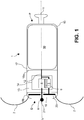
- Fig. 1 schematically shows a sectional view of a leadless pacemaker 1 for implantation into human or animal cardiac tissue according to a first embodiment.
- the leadless pacemaker 1 extends along a longitudinal axis L from a distal end D, where the leadless pacemaker 1 is to be implanted into cardiac tissue, to a proximal end P.
- an implant / explant port 11 is positioned at the proximal end P.
- the leadless pacemaker 1 may be installed for example in a ventricle or an atrium of the heart, particularly into an inner wall of the ventricle or atrium.
- the leadless pacemaker 1 comprises hook-shaped fixation elements 2 arranged at the distal end D.
- the leadless pacemaker 1 may contain more than two fixation elements 2.
- the leadless pacemaker 1 comprises a power supply 10 positioned in a power supply compartment 17 within the housing 15 adjacent the proximal end P of the leadless pacemaker 1.
- the power supply 10 may be a battery.
- the leadless pacemaker may contain an energy harvesting unit as a power source 10 or as part of the power source 10. Such an energy harvesting unit accumulates electrical energy, particularly by converting mechanical energy from motions occurring during beating of the heart to electrical energy.
- the leadless pacemaker 1 further comprises an electronic compartment 13, adjacent to the power supply compartment 17, wherein the electronic compartment 13 is separated from the power supply compartment 17 by an inner wall 18a.
- the electronic compartment 13 is hermetically sealed from the adjacent compartments in particular to avoid fluid from entering the compartment and damaging the electronics.
- an electrode compartment 19 Adjacent the electronic compartment 13, an electrode compartment 19 is positioned within the housing 15 at the distal end D of the leadless pacemaker 1.
- the electrode compartment 19 is separated from the electronic compartment 13 by inner wall 18b.
- An electronic module 14 particularly for controlling pacing (electric pulse generation) and sensing of electrical signals of the heart, among other functions, is situated within the electronic compartment 13.
- the electronic module 14 is electrically connected to the power source 10 by means of electric connection 12, which protrudes through a feedthrough of the inner wall 18a separating the electronic compartment 13 from the power supply compartment 17.
- the electronic module 14 comprises a communication unit 3 for communicating with an external device and a therapy unit 4 for generating electrical signals to electrically stimulate cardiac tissue in which the leadless pacemaker 1 is implanted. Both the communication unit 3 and the therapy unit 4 are electrically connected to power supply 10 by the electric connection 12 and thereby energized by the power supply 10.
- the communication unit 3 and the therapy unit 4 are connected by means of an integration unit 9 allowing communication between the communication unit and the therapy unit 4.
- the communication unit 3 which may be e.g. a transceiver, is electrically connected to the hook-shaped fixation elements 2 via electric connections 12 and an electrically conductive ring 20 to which the fixation elements 2 are mechanically connected.
- the ring 20 and a part of the hook-shaped fixation elements 2 are positioned within the electrode compartment 19 of the leadless pacemaker 1.
- the hook-shaped fixation elements 2 protrude through the housing 15 of the leadless pacemaker 1 to the exterior, where they are able to engage cardiac tissue when the leadless pacemaker 1 is implanted.
- the hook-shaped fixation elements 2 serve as a communication antenna which is able to generate electromagnetic waves to transmit signals generated by the communication unit 3 to an external device, for example at frequencies within the MICS band (405MHz) or the Bluetooth frequency of 2.4 GHz. Furthermore, the fixation elements 2 are also configured to receive signals from an external device, such that they can be decoded and evaluated by the communication unit 3. This allows efficient wireless communication of the leadless pacemaker 1 with external devices.
- the therapy unit 4 is electrically connected to a single pacing electrode 6, such that a positive or negative electrical potential can be applied to the pacing electrode 6 for electric stimulation of the cardiac tissue.
- the pacing electrode 6 shown in Fig. 1 is a tip electrode having a ball-shaped tip 21 with a convex surface to increase the electric field generated at the pacing electrode 6.
- the electrode compartment 19 harbors a part of the pacing electrode 6, and the pacing electrode 6 protrudes the housing 15 of the leadless pacemaker 1 via a feedthrough.
- the tip 21 of the pacing electrode 6 is positioned exterior to the leadless pacemaker and protrudes from the housing 15 of the device, such that the tip 21 is in direct contact with the cardiac tissue into which the leadless pacemaker 1 is implanted, and such that the pacing electrode 6 can electrically stimulate the cardiac tissue when an electric potential is applied to the pacing electrode 6.
- the hook-shaped fixation elements 2 which are at ground potential, serve as a counter electrode for the pacing electrode 6 in addition to their function of fixating the leadless pacemaker 1 in the cardiac tissue and their function as a communication antenna to communicate wirelessly with external devices.
- the fixation elements 2 as a counter-electrode for the pacing electrode 6 advantageously improves the local resolution of the electrical stimulation of the heart.
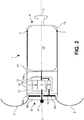
- Fig. 2 illustrates an alternative embodiment of the leadless pacemaker 1 according to the invention.
- the pacemaker 1 is identical to the one depicted in Fig. 1 (see description above) except for the following additional features or alternative features.
- the leadless pacemaker comprises a ring electrode 7 near the proximal end P of the leadless pacemaker 1.
- a ring electrode 7 In the sectional view shown in Fig. 2 , two segments of the ring electrode 7 are shown, but the ring electrode 7 extends circumferentially around the periphery of the housing 15.
- the ring electrode 7 serves as an additional counter electrode for the pacing electrode 6 and has a specialized function in signal sensing as described below.
- the electronic module 14 of the leadless pacemaker 1 comprises an additional electronic circuit 8, which is connected to the pacing electrode 6, the fixation elements 2 and the ring electrode 7.
- the electronic circuit 8 is configured to analyze a first electrical signal sensed between the pacing electrode 6 and the fixation element 2 and a second electrical signal sensed between the pacing electrode 6 and the ring electrode 7 and determine a far field signal, particularly generated in an atrium of the heart in case the leadless pacemaker is installed in the ventricle of the heart.
- this allows to separate far field signals generated distant from the implantation site of the pacemaker 1 from near field signals resulting from cardiac tissue near the implantation site.
- the communication unit 3 of the pacemaker 1 according to Fig. 2 is directly connected to the therapy unit 4 by a data connection 16.
- Fig. 3 shows a further embodiment of the leadless pacemaker 1 according to the present invention.
- the leadless pacemaker 1 in contrast to the embodiments depicted in Fig. 1 and Fig. 2 , the leadless pacemaker 1 according to Fig. 3 comprises a single fixation element 2 shaped as a helical screw extending along the longitudinal axis L from the distal end D of the leadless pacemaker 1.
- the pacemaker 1 can be anchored in the cardiac tissue at its desired location by screwing the fixation element 2 into the cardiac tissue.
- the screw-shaped fixation element 2 is connected to the communication unit 3, such that it may serve as a communication antenna to wirelessly transmit signals to and receive signals from an external device.
- the screw-shaped fixation element 2 is electrically connected to the therapy unit 4, such that a positive or negative electric potential can be applied to the fixation element 2 relative to ground potential of the housing 15 or a separate ring electrode (not shown in Fig. 3 , compare Fig. 2 ).
- the fixation element 2 may be utilized as a pacing electrode, thereby eliminating the need for a designated pacing electrode 6 as shown in Fig. 1 and Fig. 2 . This advantageously reduces weight and complexity of the leadless pacemaker 1.
- a signal splitter 5 is provided as part of the electronic module 14 of the leadless pacemaker 1 according to Fig. 3 .
- the signal splitter 5 is electrically connected to both the communication unit 3 and the therapy unit 4, and electrically connected to the helical fixation element 2 via an electrical connection 12 and an electrically conductive ring 20 to which the fixation element 2 is mechanically connected.
- the signal splitter may also be positioned outside of the electronic module 14, even outside of the electronic compartment 13.
- the communication unit 3 is directly connected to the therapy unit 4 by data connection 16.
- the communication unit 3 it is also possible to connect the communication unit 3 to the therapy unit 4 via an integration unit 9, such as depicted in Fig. 1 .
Landscapes
- Health & Medical Sciences (AREA)
- Life Sciences & Earth Sciences (AREA)
- Public Health (AREA)
- Radiology & Medical Imaging (AREA)
- Biomedical Technology (AREA)
- Animal Behavior & Ethology (AREA)
- General Health & Medical Sciences (AREA)
- Engineering & Computer Science (AREA)
- Veterinary Medicine (AREA)
- Nuclear Medicine, Radiotherapy & Molecular Imaging (AREA)
- Heart & Thoracic Surgery (AREA)
- Biophysics (AREA)
- Physics & Mathematics (AREA)
- Physiology (AREA)
- Cardiology (AREA)
- Electromagnetism (AREA)
- Acoustics & Sound (AREA)
- Electrotherapy Devices (AREA)
- Measurement And Recording Of Electrical Phenomena And Electrical Characteristics Of The Living Body (AREA)
Priority Applications (2)
| Application Number | Priority Date | Filing Date | Title |
|---|---|---|---|
| US17/003,347 US20210069516A1 (en) | 2019-09-11 | 2020-08-26 | Leadless pacemaker and methods for electrically stimulating cardiac tissue, sensing electrical signals and communicating between a leadless pacemaker and an external device |
| JP2020151698A JP2021041168A (ja) | 2019-09-11 | 2020-09-10 | リードレス・ペースメーカ、及び心臓組織を電気的に刺激し、電気信号を感知し、リードレス・ペースメーカと外部デバイスの間で通信するための方法 |
Applications Claiming Priority (1)
| Application Number | Priority Date | Filing Date | Title |
|---|---|---|---|
| US201962898563P | 2019-09-11 | 2019-09-11 |
Publications (1)
| Publication Number | Publication Date |
|---|---|
| EP3791925A1 true EP3791925A1 (fr) | 2021-03-17 |
Family
ID=68069683
Family Applications (1)
| Application Number | Title | Priority Date | Filing Date |
|---|---|---|---|
| EP19199818.6A Withdrawn EP3791925A1 (fr) | 2019-09-11 | 2019-09-26 | Stimulateur cardiaque sans conducteur et procédés de stimulation électrique de tissu cardiaque, de détection de signaux électriques et de communication entre un stimulateur cardiaque sans conducteur et un dispositif externe |
Country Status (3)
| Country | Link |
|---|---|
| US (1) | US20210069516A1 (fr) |
| EP (1) | EP3791925A1 (fr) |
| JP (1) | JP2021041168A (fr) |
Cited By (1)
| Publication number | Priority date | Publication date | Assignee | Title |
|---|---|---|---|---|
| WO2023088782A1 (fr) | 2021-11-19 | 2023-05-25 | Biotronik Se & Co. Kg | Procédé et système mis en œuvre par ordinateur pour protéger une fonction de micrologiciel critique pour patient d'un dispositif médical implantable |
Citations (4)
| Publication number | Priority date | Publication date | Assignee | Title |
|---|---|---|---|---|
| US20160121128A1 (en) * | 2014-11-03 | 2016-05-05 | Pacesetter, Inc. | Leadless dual-chamber pacing system and method |
| US20180056080A1 (en) * | 2015-01-23 | 2018-03-01 | Medtronic, Inc. | Implantable medical device with dual-use communication module |
| US20180264262A1 (en) * | 2017-03-20 | 2018-09-20 | Cardiac Pacemakers, Inc. | Systems and methods for treating cardiac arrhythmias |
| US20190030346A1 (en) | 2017-07-27 | 2019-01-31 | Pacesetter, Inc. | Leadless implantable medical device with fixation antenna member |
Family Cites Families (2)
| Publication number | Priority date | Publication date | Assignee | Title |
|---|---|---|---|---|
| US10071243B2 (en) * | 2013-07-31 | 2018-09-11 | Medtronic, Inc. | Fixation for implantable medical devices |
| US10894167B2 (en) * | 2017-12-22 | 2021-01-19 | Cardiac Pacemakers, Inc. | Implantable medical device for vascular deployment |
-
2019
- 2019-09-26 EP EP19199818.6A patent/EP3791925A1/fr not_active Withdrawn
-
2020
- 2020-08-26 US US17/003,347 patent/US20210069516A1/en not_active Abandoned
- 2020-09-10 JP JP2020151698A patent/JP2021041168A/ja active Pending
Patent Citations (4)
| Publication number | Priority date | Publication date | Assignee | Title |
|---|---|---|---|---|
| US20160121128A1 (en) * | 2014-11-03 | 2016-05-05 | Pacesetter, Inc. | Leadless dual-chamber pacing system and method |
| US20180056080A1 (en) * | 2015-01-23 | 2018-03-01 | Medtronic, Inc. | Implantable medical device with dual-use communication module |
| US20180264262A1 (en) * | 2017-03-20 | 2018-09-20 | Cardiac Pacemakers, Inc. | Systems and methods for treating cardiac arrhythmias |
| US20190030346A1 (en) | 2017-07-27 | 2019-01-31 | Pacesetter, Inc. | Leadless implantable medical device with fixation antenna member |
Cited By (1)
| Publication number | Priority date | Publication date | Assignee | Title |
|---|---|---|---|---|
| WO2023088782A1 (fr) | 2021-11-19 | 2023-05-25 | Biotronik Se & Co. Kg | Procédé et système mis en œuvre par ordinateur pour protéger une fonction de micrologiciel critique pour patient d'un dispositif médical implantable |
Also Published As
| Publication number | Publication date |
|---|---|
| US20210069516A1 (en) | 2021-03-11 |
| JP2021041168A (ja) | 2021-03-18 |
Similar Documents
| Publication | Publication Date | Title |
|---|---|---|
| US11766219B2 (en) | Cardiac stimulation system | |
| US10449354B2 (en) | Intracardiac medical device | |
| CN109562269B (zh) | 经隔膜可植入医疗设备 | |
| US9956401B2 (en) | Cardiac stimulation using intravascularly-deliverable electrode assemblies | |
| US10974056B2 (en) | Autonomous cardiac implant of the leadless capsule type, including a piezoelectric beam energy harvester | |
| US6141588A (en) | Cardiac simulation system having multiple stimulators for anti-arrhythmia therapy | |
| EP1835962B1 (fr) | Systemes de stimulation cardiaque sans fil | |
| JP4891911B2 (ja) | 線無しの心臓刺激システム | |
| CN108697898B (zh) | 用于心脏起搏的系统和方法 | |
| US9808618B2 (en) | Dual chamber intracardiac medical device | |
| US20150088155A1 (en) | Mechanical configurations for a multi-site leadless pacemaker | |
| US10905890B2 (en) | Autonomous cardiac implant of the leadless capsule type with energy harvester and controlled-charge energy storage buffer | |
| JP2020179152A (ja) | His束ペーシングを行うように構成されたリードレス心臓ペースメーカー装置 | |
| EP3986542A1 (fr) | Configuration d'électrodes pour dispositif médical | |
| US20210069516A1 (en) | Leadless pacemaker and methods for electrically stimulating cardiac tissue, sensing electrical signals and communicating between a leadless pacemaker and an external device | |
| US20220362546A1 (en) | Implantable medical device comprising an anchoring device | |
| EP4055681A1 (fr) | Stimulateur cardiaque auto-suffisant | |
| CN111107899B (zh) | 具有多种操作模式的可植入医疗装置 | |
| EP3815738A1 (fr) | Dispositif médical implantable comprenant un élément d'ancrage | |
| US10434314B2 (en) | Use of a separate device in managing the pace pulse energy of a cardiac pacemaker | |
| US10500394B1 (en) | Pacemaker system equipped with a flexible intercostal generator | |
| CN219251418U (zh) | 一种心脏起搏器及其匹配的充电设备 | |
| WO2023057341A1 (fr) | Dispositif intracardiaque et sa méthode de mise en place | |
| CN116236693A (zh) | 一种心脏起搏器及其匹配的充电设备 | |
| Kenny | Types of CRT Systems |
Legal Events
| Date | Code | Title | Description |
|---|---|---|---|
| PUAI | Public reference made under article 153(3) epc to a published international application that has entered the european phase |
Free format text: ORIGINAL CODE: 0009012 |
|
| STAA | Information on the status of an ep patent application or granted ep patent |
Free format text: STATUS: THE APPLICATION HAS BEEN PUBLISHED |
|
| AK | Designated contracting states |
Kind code of ref document: A1 Designated state(s): AL AT BE BG CH CY CZ DE DK EE ES FI FR GB GR HR HU IE IS IT LI LT LU LV MC MK MT NL NO PL PT RO RS SE SI SK SM TR |
|
| AX | Request for extension of the european patent |
Extension state: BA ME |
|
| STAA | Information on the status of an ep patent application or granted ep patent |
Free format text: STATUS: REQUEST FOR EXAMINATION WAS MADE |
|
| 17P | Request for examination filed |
Effective date: 20210909 |
|
| RBV | Designated contracting states (corrected) |
Designated state(s): AL AT BE BG CH CY CZ DE DK EE ES FI FR GB GR HR HU IE IS IT LI LT LU LV MC MK MT NL NO PL PT RO RS SE SI SK SM TR |
|
| STAA | Information on the status of an ep patent application or granted ep patent |
Free format text: STATUS: EXAMINATION IS IN PROGRESS |
|
| 17Q | First examination report despatched |
Effective date: 20230213 |
|
| STAA | Information on the status of an ep patent application or granted ep patent |
Free format text: STATUS: THE APPLICATION IS DEEMED TO BE WITHDRAWN |
|
| 18D | Application deemed to be withdrawn |
Effective date: 20230624 |