EP3791817A1 - Systems for evaluating neuromodulation therapy via hemodynamic responses - Google Patents
Systems for evaluating neuromodulation therapy via hemodynamic responses Download PDFInfo
- Publication number
- EP3791817A1 EP3791817A1 EP20205503.4A EP20205503A EP3791817A1 EP 3791817 A1 EP3791817 A1 EP 3791817A1 EP 20205503 A EP20205503 A EP 20205503A EP 3791817 A1 EP3791817 A1 EP 3791817A1
- Authority
- EP
- European Patent Office
- Prior art keywords
- neuromodulation
- electrodes
- vessel
- impedance
- distal portion
- Prior art date
- Legal status (The legal status is an assumption and is not a legal conclusion. Google has not performed a legal analysis and makes no representation as to the accuracy of the status listed.)
- Pending
Links
- 230000004007 neuromodulation Effects 0.000 title claims abstract description 402
- 230000000004 hemodynamic effect Effects 0.000 title abstract description 103
- 230000004044 response Effects 0.000 title abstract description 103
- 238000002560 therapeutic procedure Methods 0.000 title description 43
- 210000004204 blood vessel Anatomy 0.000 claims abstract description 61
- 210000002254 renal artery Anatomy 0.000 claims description 148
- 230000000638 stimulation Effects 0.000 claims description 62
- 210000002796 renal vein Anatomy 0.000 claims description 38
- 230000017531 blood circulation Effects 0.000 claims description 25
- 238000005259 measurement Methods 0.000 claims description 20
- 239000002831 pharmacologic agent Substances 0.000 claims description 20
- 238000000034 method Methods 0.000 abstract description 143
- 238000005516 engineering process Methods 0.000 abstract description 38
- 210000005036 nerve Anatomy 0.000 description 90
- 238000011282 treatment Methods 0.000 description 89
- 230000002889 sympathetic effect Effects 0.000 description 60
- 238000002679 ablation Methods 0.000 description 49
- 210000001519 tissue Anatomy 0.000 description 35
- 230000008859 change Effects 0.000 description 34
- 210000003734 kidney Anatomy 0.000 description 30
- 230000001537 neural effect Effects 0.000 description 30
- 210000002820 sympathetic nervous system Anatomy 0.000 description 29
- 238000002604 ultrasonography Methods 0.000 description 28
- 239000000126 substance Substances 0.000 description 25
- 238000001816 cooling Methods 0.000 description 24
- 239000008280 blood Substances 0.000 description 17
- 210000004369 blood Anatomy 0.000 description 17
- 210000004027 cell Anatomy 0.000 description 17
- 239000000835 fiber Substances 0.000 description 16
- 238000010438 heat treatment Methods 0.000 description 15
- 210000002569 neuron Anatomy 0.000 description 15
- 230000000144 pharmacologic effect Effects 0.000 description 15
- 210000000709 aorta Anatomy 0.000 description 13
- 206010020772 Hypertension Diseases 0.000 description 12
- 230000000694 effects Effects 0.000 description 12
- 230000003227 neuromodulating effect Effects 0.000 description 12
- 230000009467 reduction Effects 0.000 description 12
- 238000011277 treatment modality Methods 0.000 description 12
- SFLSHLFXELFNJZ-QMMMGPOBSA-N (-)-norepinephrine Chemical compound NC[C@H](O)C1=CC=C(O)C(O)=C1 SFLSHLFXELFNJZ-QMMMGPOBSA-N 0.000 description 11
- 230000004913 activation Effects 0.000 description 11
- 210000001367 artery Anatomy 0.000 description 11
- 230000006378 damage Effects 0.000 description 11
- 229960002748 norepinephrine Drugs 0.000 description 11
- SFLSHLFXELFNJZ-UHFFFAOYSA-N norepinephrine Natural products NCC(O)C1=CC=C(O)C(O)=C1 SFLSHLFXELFNJZ-UHFFFAOYSA-N 0.000 description 11
- 210000005166 vasculature Anatomy 0.000 description 11
- 230000008901 benefit Effects 0.000 description 10
- 238000002847 impedance measurement Methods 0.000 description 10
- 206010019280 Heart failures Diseases 0.000 description 9
- 230000004075 alteration Effects 0.000 description 9
- 208000020832 chronic kidney disease Diseases 0.000 description 9
- 230000033001 locomotion Effects 0.000 description 9
- 210000000056 organ Anatomy 0.000 description 9
- 210000000278 spinal cord Anatomy 0.000 description 9
- 208000003098 Ganglion Cysts Diseases 0.000 description 8
- 102100028255 Renin Human genes 0.000 description 8
- 108090000783 Renin Proteins 0.000 description 8
- 208000005400 Synovial Cyst Diseases 0.000 description 8
- 210000000609 ganglia Anatomy 0.000 description 8
- 230000001131 transforming effect Effects 0.000 description 8
- 230000001684 chronic effect Effects 0.000 description 7
- 210000002808 connective tissue Anatomy 0.000 description 7
- 230000002596 correlated effect Effects 0.000 description 7
- 201000010099 disease Diseases 0.000 description 7
- 208000037265 diseases, disorders, signs and symptoms Diseases 0.000 description 7
- 210000003484 anatomy Anatomy 0.000 description 6
- 210000003050 axon Anatomy 0.000 description 6
- 238000010586 diagram Methods 0.000 description 6
- 230000006870 function Effects 0.000 description 6
- 238000012014 optical coherence tomography Methods 0.000 description 6
- 230000003287 optical effect Effects 0.000 description 6
- 230000005855 radiation Effects 0.000 description 6
- 230000008327 renal blood flow Effects 0.000 description 6
- 230000008660 renal denervation Effects 0.000 description 6
- 230000001953 sensory effect Effects 0.000 description 6
- LFQSCWFLJHTTHZ-UHFFFAOYSA-N Ethanol Chemical compound CCO LFQSCWFLJHTTHZ-UHFFFAOYSA-N 0.000 description 5
- 206010022489 Insulin Resistance Diseases 0.000 description 5
- 208000001145 Metabolic Syndrome Diseases 0.000 description 5
- 201000000690 abdominal obesity-metabolic syndrome Diseases 0.000 description 5
- 210000004556 brain Anatomy 0.000 description 5
- 210000003169 central nervous system Anatomy 0.000 description 5
- 206010012601 diabetes mellitus Diseases 0.000 description 5
- 208000028208 end stage renal disease Diseases 0.000 description 5
- 201000000523 end stage renal failure Diseases 0.000 description 5
- 230000002093 peripheral effect Effects 0.000 description 5
- 210000000331 sympathetic ganglia Anatomy 0.000 description 5
- 210000000225 synapse Anatomy 0.000 description 5
- 230000009885 systemic effect Effects 0.000 description 5
- 208000001072 type 2 diabetes mellitus Diseases 0.000 description 5
- 230000002792 vascular Effects 0.000 description 5
- 208000004990 Cardiorenal syndrome Diseases 0.000 description 4
- DGAQECJNVWCQMB-PUAWFVPOSA-M Ilexoside XXIX Chemical compound C[C@@H]1CC[C@@]2(CC[C@@]3(C(=CC[C@H]4[C@]3(CC[C@@H]5[C@@]4(CC[C@@H](C5(C)C)OS(=O)(=O)[O-])C)C)[C@@H]2[C@]1(C)O)C)C(=O)O[C@H]6[C@@H]([C@H]([C@@H]([C@H](O6)CO)O)O)O.[Na+] DGAQECJNVWCQMB-PUAWFVPOSA-M 0.000 description 4
- 206010028851 Necrosis Diseases 0.000 description 4
- 206010047139 Vasoconstriction Diseases 0.000 description 4
- 208000027418 Wounds and injury Diseases 0.000 description 4
- 230000009471 action Effects 0.000 description 4
- 230000001154 acute effect Effects 0.000 description 4
- OIRDTQYFTABQOQ-KQYNXXCUSA-N adenosine Chemical compound C1=NC=2C(N)=NC=NC=2N1[C@@H]1O[C@H](CO)[C@@H](O)[C@H]1O OIRDTQYFTABQOQ-KQYNXXCUSA-N 0.000 description 4
- UCTWMZQNUQWSLP-UHFFFAOYSA-N adrenaline Chemical compound CNCC(O)C1=CC=C(O)C(O)=C1 UCTWMZQNUQWSLP-UHFFFAOYSA-N 0.000 description 4
- 230000036772 blood pressure Effects 0.000 description 4
- 230000030833 cell death Effects 0.000 description 4
- 230000006854 communication Effects 0.000 description 4
- 238000004891 communication Methods 0.000 description 4
- 229940079593 drug Drugs 0.000 description 4
- 239000003814 drug Substances 0.000 description 4
- 238000011156 evaluation Methods 0.000 description 4
- 239000012530 fluid Substances 0.000 description 4
- 208000014674 injury Diseases 0.000 description 4
- 238000002608 intravascular ultrasound Methods 0.000 description 4
- 230000003907 kidney function Effects 0.000 description 4
- 230000003902 lesion Effects 0.000 description 4
- 230000017074 necrotic cell death Effects 0.000 description 4
- 230000008035 nerve activity Effects 0.000 description 4
- 230000010412 perfusion Effects 0.000 description 4
- 230000000750 progressive effect Effects 0.000 description 4
- 230000002035 prolonged effect Effects 0.000 description 4
- 239000003507 refrigerant Substances 0.000 description 4
- 230000029058 respiratory gaseous exchange Effects 0.000 description 4
- 239000011734 sodium Substances 0.000 description 4
- 229910052708 sodium Inorganic materials 0.000 description 4
- 210000002466 splanchnic nerve Anatomy 0.000 description 4
- 230000001225 therapeutic effect Effects 0.000 description 4
- 230000025033 vasoconstriction Effects 0.000 description 4
- 208000007177 Left Ventricular Hypertrophy Diseases 0.000 description 3
- 206010041277 Sodium retention Diseases 0.000 description 3
- 210000001943 adrenal medulla Anatomy 0.000 description 3
- 210000004079 adrenergic fiber Anatomy 0.000 description 3
- 230000009286 beneficial effect Effects 0.000 description 3
- 230000033228 biological regulation Effects 0.000 description 3
- 230000036760 body temperature Effects 0.000 description 3
- 230000000747 cardiac effect Effects 0.000 description 3
- 239000003795 chemical substances by application Substances 0.000 description 3
- 238000002591 computed tomography Methods 0.000 description 3
- 230000002638 denervation Effects 0.000 description 3
- 238000013461 design Methods 0.000 description 3
- 230000010339 dilation Effects 0.000 description 3
- 210000001105 femoral artery Anatomy 0.000 description 3
- 238000002594 fluoroscopy Methods 0.000 description 3
- 230000024924 glomerular filtration Effects 0.000 description 3
- 230000002631 hypothermal effect Effects 0.000 description 3
- 210000003090 iliac artery Anatomy 0.000 description 3
- 238000003384 imaging method Methods 0.000 description 3
- 238000002347 injection Methods 0.000 description 3
- 239000007924 injection Substances 0.000 description 3
- 230000030214 innervation Effects 0.000 description 3
- 208000017169 kidney disease Diseases 0.000 description 3
- 230000001404 mediated effect Effects 0.000 description 3
- 230000008904 neural response Effects 0.000 description 3
- 210000001428 peripheral nervous system Anatomy 0.000 description 3
- 210000000115 thoracic cavity Anatomy 0.000 description 3
- 230000024883 vasodilation Effects 0.000 description 3
- 210000001631 vena cava inferior Anatomy 0.000 description 3
- UCTWMZQNUQWSLP-VIFPVBQESA-N (R)-adrenaline Chemical compound CNC[C@H](O)C1=CC=C(O)C(O)=C1 UCTWMZQNUQWSLP-VIFPVBQESA-N 0.000 description 2
- 229930182837 (R)-adrenaline Natural products 0.000 description 2
- 239000005541 ACE inhibitor Substances 0.000 description 2
- 108060003345 Adrenergic Receptor Proteins 0.000 description 2
- 102000017910 Adrenergic receptor Human genes 0.000 description 2
- PQSUYGKTWSAVDQ-ZVIOFETBSA-N Aldosterone Chemical compound C([C@@]1([C@@H](C(=O)CO)CC[C@H]1[C@@H]1CC2)C=O)[C@H](O)[C@@H]1[C@]1(C)C2=CC(=O)CC1 PQSUYGKTWSAVDQ-ZVIOFETBSA-N 0.000 description 2
- PQSUYGKTWSAVDQ-UHFFFAOYSA-N Aldosterone Natural products C1CC2C3CCC(C(=O)CO)C3(C=O)CC(O)C2C2(C)C1=CC(=O)CC2 PQSUYGKTWSAVDQ-UHFFFAOYSA-N 0.000 description 2
- 102000005862 Angiotensin II Human genes 0.000 description 2
- 101800000733 Angiotensin-2 Proteins 0.000 description 2
- 239000002126 C01EB10 - Adenosine Substances 0.000 description 2
- 241001164374 Calyx Species 0.000 description 2
- 206010007558 Cardiac failure chronic Diseases 0.000 description 2
- 208000024172 Cardiovascular disease Diseases 0.000 description 2
- 208000007530 Essential hypertension Diseases 0.000 description 2
- 206010016803 Fluid overload Diseases 0.000 description 2
- 241000282412 Homo Species 0.000 description 2
- CZGUSIXMZVURDU-JZXHSEFVSA-N Ile(5)-angiotensin II Chemical compound C([C@@H](C(=O)N[C@@H]([C@@H](C)CC)C(=O)N[C@@H](CC=1NC=NC=1)C(=O)N1[C@@H](CCC1)C(=O)N[C@@H](CC=1C=CC=CC=1)C([O-])=O)NC(=O)[C@@H](NC(=O)[C@H](CCCNC(N)=[NH2+])NC(=O)[C@@H]([NH3+])CC([O-])=O)C(C)C)C1=CC=C(O)C=C1 CZGUSIXMZVURDU-JZXHSEFVSA-N 0.000 description 2
- 208000001132 Osteoporosis Diseases 0.000 description 2
- 206010035039 Piloerection Diseases 0.000 description 2
- 206010037211 Psychomotor hyperactivity Diseases 0.000 description 2
- 208000004531 Renal Artery Obstruction Diseases 0.000 description 2
- 206010038378 Renal artery stenosis Diseases 0.000 description 2
- 206010042434 Sudden death Diseases 0.000 description 2
- 239000000219 Sympatholytic Substances 0.000 description 2
- 208000007536 Thrombosis Diseases 0.000 description 2
- OIPILFWXSMYKGL-UHFFFAOYSA-N acetylcholine Chemical compound CC(=O)OCC[N+](C)(C)C OIPILFWXSMYKGL-UHFFFAOYSA-N 0.000 description 2
- 229960004373 acetylcholine Drugs 0.000 description 2
- 229960005305 adenosine Drugs 0.000 description 2
- 230000002411 adverse Effects 0.000 description 2
- 229960002478 aldosterone Drugs 0.000 description 2
- 239000002333 angiotensin II receptor antagonist Substances 0.000 description 2
- 229950006323 angiotensin ii Drugs 0.000 description 2
- 229940125364 angiotensin receptor blocker Drugs 0.000 description 2
- 229940044094 angiotensin-converting-enzyme inhibitor Drugs 0.000 description 2
- 210000002376 aorta thoracic Anatomy 0.000 description 2
- 230000006907 apoptotic process Effects 0.000 description 2
- 238000013459 approach Methods 0.000 description 2
- 210000004191 axillary artery Anatomy 0.000 description 2
- 239000002876 beta blocker Substances 0.000 description 2
- 229940097320 beta blocking agent Drugs 0.000 description 2
- 230000005540 biological transmission Effects 0.000 description 2
- 230000015572 biosynthetic process Effects 0.000 description 2
- 210000002302 brachial artery Anatomy 0.000 description 2
- 230000005779 cell damage Effects 0.000 description 2
- 208000037887 cell injury Diseases 0.000 description 2
- 210000000038 chest Anatomy 0.000 description 2
- 230000008602 contraction Effects 0.000 description 2
- 230000005574 cross-species transmission Effects 0.000 description 2
- 230000034994 death Effects 0.000 description 2
- 230000003247 decreasing effect Effects 0.000 description 2
- 230000003111 delayed effect Effects 0.000 description 2
- 230000001419 dependent effect Effects 0.000 description 2
- 239000002934 diuretic Substances 0.000 description 2
- 229940030606 diuretics Drugs 0.000 description 2
- 230000005684 electric field Effects 0.000 description 2
- 229960005139 epinephrine Drugs 0.000 description 2
- 235000019441 ethanol Nutrition 0.000 description 2
- 238000009472 formulation Methods 0.000 description 2
- 210000004907 gland Anatomy 0.000 description 2
- 230000010243 gut motility Effects 0.000 description 2
- 235000003642 hunger Nutrition 0.000 description 2
- 208000013403 hyperactivity Diseases 0.000 description 2
- 230000001631 hypertensive effect Effects 0.000 description 2
- 230000001939 inductive effect Effects 0.000 description 2
- 238000001802 infusion Methods 0.000 description 2
- 210000002439 juxtaglomerular apparatus Anatomy 0.000 description 2
- 210000005246 left atrium Anatomy 0.000 description 2
- 210000005240 left ventricle Anatomy 0.000 description 2
- 230000000670 limiting effect Effects 0.000 description 2
- 210000004072 lung Anatomy 0.000 description 2
- 239000000203 mixture Substances 0.000 description 2
- 230000007383 nerve stimulation Effects 0.000 description 2
- 230000007604 neuronal communication Effects 0.000 description 2
- 239000002581 neurotoxin Substances 0.000 description 2
- 231100000618 neurotoxin Toxicity 0.000 description 2
- 235000015097 nutrients Nutrition 0.000 description 2
- 210000004789 organ system Anatomy 0.000 description 2
- XQYZDYMELSJDRZ-UHFFFAOYSA-N papaverine Chemical compound C1=C(OC)C(OC)=CC=C1CC1=NC=CC2=CC(OC)=C(OC)C=C12 XQYZDYMELSJDRZ-UHFFFAOYSA-N 0.000 description 2
- 230000036961 partial effect Effects 0.000 description 2
- 230000007310 pathophysiology Effects 0.000 description 2
- 230000035479 physiological effects, processes and functions Effects 0.000 description 2
- 230000001242 postsynaptic effect Effects 0.000 description 2
- 230000003518 presynaptic effect Effects 0.000 description 2
- 230000037452 priming Effects 0.000 description 2
- 210000001747 pupil Anatomy 0.000 description 2
- 230000010344 pupil dilation Effects 0.000 description 2
- 210000002321 radial artery Anatomy 0.000 description 2
- 230000009103 reabsorption Effects 0.000 description 2
- 230000002829 reductive effect Effects 0.000 description 2
- 230000008085 renal dysfunction Effects 0.000 description 2
- 230000036454 renin-angiotensin system Effects 0.000 description 2
- 210000005245 right atrium Anatomy 0.000 description 2
- 230000028327 secretion Effects 0.000 description 2
- 230000009295 sperm incapacitation Effects 0.000 description 2
- 230000004936 stimulating effect Effects 0.000 description 2
- 230000004083 survival effect Effects 0.000 description 2
- 230000002459 sustained effect Effects 0.000 description 2
- 230000035900 sweating Effects 0.000 description 2
- 230000008700 sympathetic activation Effects 0.000 description 2
- 238000012360 testing method Methods 0.000 description 2
- 238000010257 thawing Methods 0.000 description 2
- 238000007669 thermal treatment Methods 0.000 description 2
- 238000012546 transfer Methods 0.000 description 2
- 210000005239 tubule Anatomy 0.000 description 2
- 230000002485 urinary effect Effects 0.000 description 2
- 229940124549 vasodilator Drugs 0.000 description 2
- 239000003071 vasodilator agent Substances 0.000 description 2
- 229930008281 A03AD01 - Papaverine Natural products 0.000 description 1
- 201000001320 Atherosclerosis Diseases 0.000 description 1
- 208000037260 Atherosclerotic Plaque Diseases 0.000 description 1
- 101800004538 Bradykinin Proteins 0.000 description 1
- 102400000967 Bradykinin Human genes 0.000 description 1
- 206010007559 Cardiac failure congestive Diseases 0.000 description 1
- 108010009685 Cholinergic Receptors Proteins 0.000 description 1
- 108090000790 Enzymes Proteins 0.000 description 1
- 102000004190 Enzymes Human genes 0.000 description 1
- 208000010228 Erectile Dysfunction Diseases 0.000 description 1
- QXZGBUJJYSLZLT-UHFFFAOYSA-N H-Arg-Pro-Pro-Gly-Phe-Ser-Pro-Phe-Arg-OH Natural products NC(N)=NCCCC(N)C(=O)N1CCCC1C(=O)N1C(C(=O)NCC(=O)NC(CC=2C=CC=CC=2)C(=O)NC(CO)C(=O)N2C(CCC2)C(=O)NC(CC=2C=CC=CC=2)C(=O)NC(CCCN=C(N)N)C(O)=O)CCC1 QXZGBUJJYSLZLT-UHFFFAOYSA-N 0.000 description 1
- 208000029422 Hypernatremia Diseases 0.000 description 1
- 206010061216 Infarction Diseases 0.000 description 1
- 208000028389 Nerve injury Diseases 0.000 description 1
- 101710138657 Neurotoxin Proteins 0.000 description 1
- 102000019315 Nicotinic acetylcholine receptors Human genes 0.000 description 1
- 108050006807 Nicotinic acetylcholine receptors Proteins 0.000 description 1
- ISWSIDIOOBJBQZ-UHFFFAOYSA-N Phenol Chemical compound OC1=CC=CC=C1 ISWSIDIOOBJBQZ-UHFFFAOYSA-N 0.000 description 1
- 206010061481 Renal injury Diseases 0.000 description 1
- 206010063897 Renal ischaemia Diseases 0.000 description 1
- 206010049418 Sudden Cardiac Death Diseases 0.000 description 1
- 208000024248 Vascular System injury Diseases 0.000 description 1
- 208000012339 Vascular injury Diseases 0.000 description 1
- 206010047281 Ventricular arrhythmia Diseases 0.000 description 1
- 206010047700 Vomiting Diseases 0.000 description 1
- 238000010317 ablation therapy Methods 0.000 description 1
- 238000011298 ablation treatment Methods 0.000 description 1
- 102000034337 acetylcholine receptors Human genes 0.000 description 1
- 230000003213 activating effect Effects 0.000 description 1
- 206010000891 acute myocardial infarction Diseases 0.000 description 1
- 230000003044 adaptive effect Effects 0.000 description 1
- 230000002730 additional effect Effects 0.000 description 1
- 239000005557 antagonist Substances 0.000 description 1
- 230000003466 anti-cipated effect Effects 0.000 description 1
- 210000000702 aorta abdominal Anatomy 0.000 description 1
- 210000005249 arterial vasculature Anatomy 0.000 description 1
- 230000002567 autonomic effect Effects 0.000 description 1
- 210000003403 autonomic nervous system Anatomy 0.000 description 1
- 210000000467 autonomic pathway Anatomy 0.000 description 1
- 230000004323 axial length Effects 0.000 description 1
- 230000002457 bidirectional effect Effects 0.000 description 1
- 230000000903 blocking effect Effects 0.000 description 1
- 238000009530 blood pressure measurement Methods 0.000 description 1
- QXZGBUJJYSLZLT-FDISYFBBSA-N bradykinin Chemical compound NC(=N)NCCC[C@H](N)C(=O)N1CCC[C@H]1C(=O)N1[C@H](C(=O)NCC(=O)N[C@@H](CC=2C=CC=CC=2)C(=O)N[C@@H](CO)C(=O)N2[C@@H](CCC2)C(=O)N[C@@H](CC=2C=CC=CC=2)C(=O)N[C@@H](CCCNC(N)=N)C(O)=O)CCC1 QXZGBUJJYSLZLT-FDISYFBBSA-N 0.000 description 1
- 210000000748 cardiovascular system Anatomy 0.000 description 1
- 150000003943 catecholamines Chemical class 0.000 description 1
- 210000005056 cell body Anatomy 0.000 description 1
- 230000001112 coagulating effect Effects 0.000 description 1
- 239000002131 composite material Substances 0.000 description 1
- 230000000875 corresponding effect Effects 0.000 description 1
- 210000001787 dendrite Anatomy 0.000 description 1
- 238000009792 diffusion process Methods 0.000 description 1
- 230000000916 dilatatory effect Effects 0.000 description 1
- 238000010790 dilution Methods 0.000 description 1
- 239000012895 dilution Substances 0.000 description 1
- 238000002224 dissection Methods 0.000 description 1
- 230000002222 downregulating effect Effects 0.000 description 1
- 230000003828 downregulation Effects 0.000 description 1
- 238000002592 echocardiography Methods 0.000 description 1
- 230000005611 electricity Effects 0.000 description 1
- 238000001962 electrophoresis Methods 0.000 description 1
- 230000008030 elimination Effects 0.000 description 1
- 238000003379 elimination reaction Methods 0.000 description 1
- 210000000105 enteric nervous system Anatomy 0.000 description 1
- 230000007613 environmental effect Effects 0.000 description 1
- 210000003238 esophagus Anatomy 0.000 description 1
- 210000003191 femoral vein Anatomy 0.000 description 1
- 210000001035 gastrointestinal tract Anatomy 0.000 description 1
- ACGDKVXYNVEAGU-UHFFFAOYSA-N guanethidine Chemical compound NC(N)=NCCN1CCCCCCC1 ACGDKVXYNVEAGU-UHFFFAOYSA-N 0.000 description 1
- 229960003602 guanethidine Drugs 0.000 description 1
- 210000003128 head Anatomy 0.000 description 1
- 230000009097 homeostatic mechanism Effects 0.000 description 1
- 230000013632 homeostatic process Effects 0.000 description 1
- 230000003054 hormonal effect Effects 0.000 description 1
- 230000001077 hypotensive effect Effects 0.000 description 1
- 210000003111 iliac vein Anatomy 0.000 description 1
- 201000001881 impotence Diseases 0.000 description 1
- 238000012623 in vivo measurement Methods 0.000 description 1
- 230000007574 infarction Effects 0.000 description 1
- 230000002401 inhibitory effect Effects 0.000 description 1
- 230000000977 initiatory effect Effects 0.000 description 1
- 230000002427 irreversible effect Effects 0.000 description 1
- 208000028867 ischemia Diseases 0.000 description 1
- 210000000244 kidney pelvis Anatomy 0.000 description 1
- 210000002429 large intestine Anatomy 0.000 description 1
- 210000003041 ligament Anatomy 0.000 description 1
- 230000007774 longterm Effects 0.000 description 1
- 210000004705 lumbosacral region Anatomy 0.000 description 1
- 230000014759 maintenance of location Effects 0.000 description 1
- 238000007726 management method Methods 0.000 description 1
- 238000013507 mapping Methods 0.000 description 1
- 239000000463 material Substances 0.000 description 1
- 230000007246 mechanism Effects 0.000 description 1
- 230000028161 membrane depolarization Effects 0.000 description 1
- 238000012986 modification Methods 0.000 description 1
- 230000004048 modification Effects 0.000 description 1
- 230000004899 motility Effects 0.000 description 1
- 230000008764 nerve damage Effects 0.000 description 1
- 210000004126 nerve fiber Anatomy 0.000 description 1
- 210000000653 nervous system Anatomy 0.000 description 1
- 210000000118 neural pathway Anatomy 0.000 description 1
- 230000010004 neural pathway Effects 0.000 description 1
- 230000001272 neurogenic effect Effects 0.000 description 1
- 239000002858 neurotransmitter agent Substances 0.000 description 1
- 230000007935 neutral effect Effects 0.000 description 1
- 229960001789 papaverine Drugs 0.000 description 1
- 230000001734 parasympathetic effect Effects 0.000 description 1
- 210000001002 parasympathetic nervous system Anatomy 0.000 description 1
- 230000008855 peristalsis Effects 0.000 description 1
- 230000005371 pilomotor reflex Effects 0.000 description 1
- 230000036470 plasma concentration Effects 0.000 description 1
- 208000030761 polycystic kidney disease Diseases 0.000 description 1
- 201000010065 polycystic ovary syndrome Diseases 0.000 description 1
- 210000002970 posterior hypothalamus Anatomy 0.000 description 1
- 238000002360 preparation method Methods 0.000 description 1
- 230000008569 process Effects 0.000 description 1
- 239000000700 radioactive tracer Substances 0.000 description 1
- 230000001105 regulatory effect Effects 0.000 description 1
- 230000009711 regulatory function Effects 0.000 description 1
- 230000000241 respiratory effect Effects 0.000 description 1
- 230000003938 response to stress Effects 0.000 description 1
- 210000005241 right ventricle Anatomy 0.000 description 1
- 210000002265 sensory receptor cell Anatomy 0.000 description 1
- 102000027509 sensory receptors Human genes 0.000 description 1
- 108091008691 sensory receptors Proteins 0.000 description 1
- 230000000392 somatic effect Effects 0.000 description 1
- 210000001032 spinal nerve Anatomy 0.000 description 1
- 210000003270 subclavian artery Anatomy 0.000 description 1
- 210000000106 sweat gland Anatomy 0.000 description 1
- 230000002782 sympathoadrenal effect Effects 0.000 description 1
- 230000000946 synaptic effect Effects 0.000 description 1
- 230000005062 synaptic transmission Effects 0.000 description 1
- 238000009210 therapy by ultrasound Methods 0.000 description 1
- 230000000451 tissue damage Effects 0.000 description 1
- 231100000827 tissue damage Toxicity 0.000 description 1
- 238000002054 transplantation Methods 0.000 description 1
- 238000011269 treatment regimen Methods 0.000 description 1
- 210000000626 ureter Anatomy 0.000 description 1
- 208000019553 vascular disease Diseases 0.000 description 1
- 210000003462 vein Anatomy 0.000 description 1
- 230000002861 ventricular Effects 0.000 description 1
- 230000008673 vomiting Effects 0.000 description 1
- 230000002618 waking effect Effects 0.000 description 1
- 210000000707 wrist Anatomy 0.000 description 1
Images


Classifications
-
- A—HUMAN NECESSITIES
- A61—MEDICAL OR VETERINARY SCIENCE; HYGIENE
- A61B—DIAGNOSIS; SURGERY; IDENTIFICATION
- A61B5/00—Measuring for diagnostic purposes; Identification of persons
- A61B5/05—Detecting, measuring or recording for diagnosis by means of electric currents or magnetic fields; Measuring using microwaves or radio waves
- A61B5/053—Measuring electrical impedance or conductance of a portion of the body
- A61B5/0538—Measuring electrical impedance or conductance of a portion of the body invasively, e.g. using a catheter
-
- A—HUMAN NECESSITIES
- A61—MEDICAL OR VETERINARY SCIENCE; HYGIENE
- A61B—DIAGNOSIS; SURGERY; IDENTIFICATION
- A61B18/00—Surgical instruments, devices or methods for transferring non-mechanical forms of energy to or from the body
- A61B18/04—Surgical instruments, devices or methods for transferring non-mechanical forms of energy to or from the body by heating
- A61B18/12—Surgical instruments, devices or methods for transferring non-mechanical forms of energy to or from the body by heating by passing a current through the tissue to be heated, e.g. high-frequency current
- A61B18/1206—Generators therefor
-
- A—HUMAN NECESSITIES
- A61—MEDICAL OR VETERINARY SCIENCE; HYGIENE
- A61B—DIAGNOSIS; SURGERY; IDENTIFICATION
- A61B18/00—Surgical instruments, devices or methods for transferring non-mechanical forms of energy to or from the body
- A61B18/04—Surgical instruments, devices or methods for transferring non-mechanical forms of energy to or from the body by heating
- A61B18/12—Surgical instruments, devices or methods for transferring non-mechanical forms of energy to or from the body by heating by passing a current through the tissue to be heated, e.g. high-frequency current
- A61B18/14—Probes or electrodes therefor
- A61B18/1492—Probes or electrodes therefor having a flexible, catheter-like structure, e.g. for heart ablation
-
- A—HUMAN NECESSITIES
- A61—MEDICAL OR VETERINARY SCIENCE; HYGIENE
- A61B—DIAGNOSIS; SURGERY; IDENTIFICATION
- A61B5/00—Measuring for diagnostic purposes; Identification of persons
- A61B5/48—Other medical applications
- A61B5/4848—Monitoring or testing the effects of treatment, e.g. of medication
-
- A—HUMAN NECESSITIES
- A61—MEDICAL OR VETERINARY SCIENCE; HYGIENE
- A61M—DEVICES FOR INTRODUCING MEDIA INTO, OR ONTO, THE BODY; DEVICES FOR TRANSDUCING BODY MEDIA OR FOR TAKING MEDIA FROM THE BODY; DEVICES FOR PRODUCING OR ENDING SLEEP OR STUPOR
- A61M25/00—Catheters; Hollow probes
- A61M25/0043—Catheters; Hollow probes characterised by structural features
-
- A—HUMAN NECESSITIES
- A61—MEDICAL OR VETERINARY SCIENCE; HYGIENE
- A61B—DIAGNOSIS; SURGERY; IDENTIFICATION
- A61B18/00—Surgical instruments, devices or methods for transferring non-mechanical forms of energy to or from the body
- A61B2018/00315—Surgical instruments, devices or methods for transferring non-mechanical forms of energy to or from the body for treatment of particular body parts
- A61B2018/00345—Vascular system
- A61B2018/00404—Blood vessels other than those in or around the heart
-
- A—HUMAN NECESSITIES
- A61—MEDICAL OR VETERINARY SCIENCE; HYGIENE
- A61B—DIAGNOSIS; SURGERY; IDENTIFICATION
- A61B18/00—Surgical instruments, devices or methods for transferring non-mechanical forms of energy to or from the body
- A61B2018/00315—Surgical instruments, devices or methods for transferring non-mechanical forms of energy to or from the body for treatment of particular body parts
- A61B2018/00434—Neural system
-
- A—HUMAN NECESSITIES
- A61—MEDICAL OR VETERINARY SCIENCE; HYGIENE
- A61B—DIAGNOSIS; SURGERY; IDENTIFICATION
- A61B18/00—Surgical instruments, devices or methods for transferring non-mechanical forms of energy to or from the body
- A61B2018/00315—Surgical instruments, devices or methods for transferring non-mechanical forms of energy to or from the body for treatment of particular body parts
- A61B2018/00505—Urinary tract
- A61B2018/00511—Kidney
-
- A—HUMAN NECESSITIES
- A61—MEDICAL OR VETERINARY SCIENCE; HYGIENE
- A61B—DIAGNOSIS; SURGERY; IDENTIFICATION
- A61B18/00—Surgical instruments, devices or methods for transferring non-mechanical forms of energy to or from the body
- A61B2018/00571—Surgical instruments, devices or methods for transferring non-mechanical forms of energy to or from the body for achieving a particular surgical effect
- A61B2018/00577—Ablation
-
- A—HUMAN NECESSITIES
- A61—MEDICAL OR VETERINARY SCIENCE; HYGIENE
- A61B—DIAGNOSIS; SURGERY; IDENTIFICATION
- A61B18/00—Surgical instruments, devices or methods for transferring non-mechanical forms of energy to or from the body
- A61B2018/00636—Sensing and controlling the application of energy
- A61B2018/00666—Sensing and controlling the application of energy using a threshold value
-
- A—HUMAN NECESSITIES
- A61—MEDICAL OR VETERINARY SCIENCE; HYGIENE
- A61B—DIAGNOSIS; SURGERY; IDENTIFICATION
- A61B18/00—Surgical instruments, devices or methods for transferring non-mechanical forms of energy to or from the body
- A61B2018/00636—Sensing and controlling the application of energy
- A61B2018/00773—Sensed parameters
- A61B2018/00875—Resistance or impedance
-
- A—HUMAN NECESSITIES
- A61—MEDICAL OR VETERINARY SCIENCE; HYGIENE
- A61N—ELECTROTHERAPY; MAGNETOTHERAPY; RADIATION THERAPY; ULTRASOUND THERAPY
- A61N1/00—Electrotherapy; Circuits therefor
- A61N1/02—Details
- A61N1/04—Electrodes
- A61N1/05—Electrodes for implantation or insertion into the body, e.g. heart electrode
Definitions
- the present technology is related to neuromodulation.
- various embodiments of the present technology are related to systems and methods for assessing the efficacy of neuromodulation therapy via hemodynamic responses to stimuli.
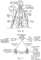
- the sympathetic nervous system is a primarily involuntary bodily control system typically associated with stress responses. Fibers of the SNS extend through tissue in almost every organ system of the human body and can affect characteristics such as pupil diameter, gut motility, and urinary output. Such regulation can have adaptive utility in maintaining homeostasis or in preparing the body for rapid response to environmental factors. Chronic activation of the SNS, however, is a common maladaptive response that can drive the progression of many disease states. Excessive activation of the renal SNS in particular has been identified experimentally and in humans as a likely contributor to the complex pathophysiology of hypertension, states of volume overload (e.g., heart failure), and progressive renal disease.
- states of volume overload e.g., heart failure
- Sympathetic nerves of the kidneys terminate in the renal blood vessels, the juxtaglomerular apparatus, and the renal tubules, among other structures. Stimulation of the renal sympathetic nerves can cause, for example, increased renin release, increased sodium reabsorption, and reduced renal blood flow. These and other neural-regulated components of renal function are considerably stimulated in disease states characterized by heightened sympathetic tone. For example, reduced renal blood flow and glomerular filtration rate as a result of renal sympathetic efferent stimulation is likely a cornerstone of the loss of renal function in cardio-renal syndrome, (i.e., renal dysfunction as a progressive complication of chronic heart failure).
- Pharmacologic strategies to thwart the consequences of renal sympathetic stimulation include centrally-acting sympatholytic drugs, beta blockers (e.g., to reduce renin release), angiotensin-converting enzyme inhibitors and receptor blockers (e.g., to block the action of angiotensin II and aldosterone activation consequent to renin release), and diuretics (e.g., to counter the renal sympathetic mediated sodium and water retention).
- beta blockers e.g., to reduce renin release
- angiotensin-converting enzyme inhibitors and receptor blockers e.g., to block the action of angiotensin II and aldosterone activation consequent to renin release
- diuretics e.g., to counter the renal sympathetic mediated sodium and water retention.
- Systems and methods in accordance with embodiments of the present technology can be configured to detect hemodynamic responses to stimuli before and after neuromodulation therapy. This information can be used to assess the efficacy of neuromodulation therapy in substantially real time during neuromodulation procedures. Specific details of several embodiments of the present technology are described herein with reference to FIGS. 1-13 . Although many of the embodiments are described with respect to devices, systems, and methods for intravascular renal neuromodulation, other applications and other embodiments in addition to those described herein are within the scope of the present technology. For example, at least some embodiments of the present technology may be useful for intraluminal neuromodulation, for extravascular neuromodulation, for non-renal neuromodulation, and/or for use in therapies other than neuromodulation.
- embodiments of the present technology can have different configurations, components, and/or procedures than those shown or described herein.
- a person of ordinary skill in the art will understand that embodiments of the present technology can have configurations, components, and/or procedures in addition to those shown or described herein and that these and other embodiments can be without several of the configurations, components, and/or procedures shown or described herein without deviating from the present technology.
- distal and proximal define a position or direction with respect to a clinician or a clinician's control device (e.g., a handle of a neuromodulation device).
- distal and disally refer to a position distant from or in a direction away from a clinician or a clinician's control device.
- proximal and proximally refer to a position near or in a direction toward a clinician or a clinician's control device.
- FIGS. 1A and 1B are partially schematic side views of a system 100 for applying and evaluating neuromodulation therapy (“system 100") configured in accordance with an embodiment of the present technology.
- the system 100 includes a neuromodulation catheter 102 and a controller 104 communicatively coupled to the neuromodulation catheter 102 via a wired or wireless communication link.
- the neuromodulation catheter 102 is in a first state or arrangement in which a distal portion of the neuromodulation catheter 102 is at least generally straight along a portion of a blood vessel V.
- the neuromodulation catheter 102 is in a second state or arrangement in which the distal portion of the neuromodulation catheter 102 is transformed or otherwise expanded to a spiral/helical shape.
- the neuromodulation catheter 102 includes an elongated shaft 106 having a distal portion 108a configured to be positioned at a target site within a blood vessel of a human patient (e.g., a renal artery) and a proximal portion 108b that extends outside of the patient to a handle (not shown) or other feature that allows an operator (not shown) to manipulate the distal portion 108a of the shaft 106.
- the neuromodulation catheter 102 also includes a plurality of energy delivery elements, such as electrodes (identified individually as first through fourth electrodes 110a-110d, respectively, and referred to collectively as electrodes 110) spaced along the distal portion 108a of the shaft 106.
- the neuromodulation catheter 102 includes four electrodes 110. In other embodiments, however, the neuromodulation catheter 102 may include one, two, three, or more than four electrodes 110, and/or may include different energy delivery elements.
- the electrodes 110 and/or another type of energy delivery element can deliver neuromodulation energy to the target site to modulate or ablate nerves (e.g., renal nerves) proximate to the target site.
- the electrodes 110 and/or other features at the distal portion 108a of the shaft 106 can further be configured to apply stimuli at and/or proximate to the target site before and/or after neuromodulation, and detect a hemodynamic response caused by the stimuli.
- Stimuli refers to stimulations that are sufficient to evoke a neural response in nerves proximate to the vessel V (e.g., renal nerves), but not so great that they permanently affect neural functions.
- the stimuli can be applied proximal to the site of neuromodulation, distal to the site of neuromodulation, and/or on either side of the neuromodulation site.
- the stimuli is applied at the ostium of a vessel (e.g., the ostium of the renal artery). In other embodiments, however, the stimuli may be applied at other suitable locations.
- a successful or effective neuromodulation treatment or therapy causes a hemodynamic response, which can be reflected by a local change in hemodynamics and/or a global change in hemodynamics.
- Local changes in hemodynamics can be characterized by hemodynamic responses caused by efferent nerve activity, whereas global changes in hemodynamics can be characterized by hemodynamic responses caused by afferent nerve activity.
- Changes in hemodynamics such as changes in vessel diameter, can be detected as a result of successful denervation without the application of a stimulus. For example, the diameter, cross-sectional area, or segmental volume of a vessel can be measured immediately before and after neuromodulation therapy.
- Increases in the vessel dimension may be indicative of a successful neuromodulation treatment because the modulation or ablation of the efferent nerves is expected to cause an immediate decrease or removal sympathetically induced vasoconstriction, causing a decrease in vessel tone and dilating the vessel.
- a hemodynamic response can be measured by stimulating nerves at or proximate to the neuromodulation site before and after neuromodulation therapy, and detecting a change in hemodynamic response caused by each stimulus.
- an electrical or pharmaceutical stimulus can be applied to a vessel to stimulate the nerves at or proximate to the target site.
- the afferent nerves When the nerves are functioning (i.e., conducting signals), the afferent nerves will respond to the stimulus and cause a hemodynamic response.
- This hemodynamic response can be measured by detecting changes in vessel dimension (e.g., diameter, cross-sectional area, and segmental volume), pressure within the vessel, blow flow through the vessel, heart rate, and/or other parameters indicative of a hemodynamic response. It is expected that the hemodynamic response to the stimulus will be eliminated or at least lessened after the nerves have been effectively ablated to a desired degree because the afferent nerves have been ablated or modulated. Accordingly, comparing the hemodynamic responses before and after neuromodulation is expected to indicate whether a neuromodulation treatment is successful.
- vessel dimensions or other hemodynamic parameters can be measured before and after neuromodulation therapy (without stimulation) to determine the efficacy of the neuromodulation treatment on efferent nerves proximate to the vessel, and also measured before and after neuromodulation therapy as a response to stimuli to determine the efficacy of the neuromodulation treatment on afferent nerves.
- the electrodes 110 can be configured to: (1) apply stimuli to the vessel V, and (2) detect/measure changes in vessel impedance caused by the stimuli, which can be correlated to changes in vessel diameter.
- vessel impedance is lower when the vessel has a larger diameter (i.e., when more blood is contained in the vessel) and higher when the vessel has a smaller diameter (i.e., when less blood is contained in the vessel).
- impedance measurements taken by the electrode(s) 110 in response to the stimuli can be correlated to changes in vessel diameter, segmental volume, and/or cross-sectional area (i.e., a hemodynamic response), and used to assess the efficacy of the neuromodulation treatment.
- the neuromodulation procedure itself may cause immediate dilation of the vessel V (e.g., the renal artery) due to immediate removal of sympathetically induced vasoconstriction.
- one or more of the electrodes 110 can be used to measure a segmental volume of the vessel V, a cross-sectional area of the vessel V, and/or a vessel diameter just before and after neuromodulation (i.e., ablation), and these measurements may indicate an immediate dilation of the vessel V and a successful therapeutic result.
- these parameters can be determined using quadripolar impedance measurements, which are detected by applying a substantially homogeneous electric field across the electrodes 110 (e.g., generated by the first and fourth electrodes 110a and 110d) to allow for accurate impedance measurements (e.g., detected by the second and third electrodes 110b and 110c).
- the distal portion 108a of the shaft 106 can be positioned along a portion of the vessel V in a substantially straight configuration.
- One or more of the electrodes 110 can be used to detect a baseline impedance measurement before neuromodulation energy is applied to the target site.
- the initial impedance of the vessel V can be detected across the second and third electrodes 110b and 110c (i.e., the inner two electrodes), and this initial impedance can be correlated to the vessel diameter, vessel area, and/or vessel volume (e.g., via the controller 104) using the cylindrical equation described by Baan and/or using known physical relationships between impedance and vessel dimensions (e.g., as described in Hettrick DA, Battocletti J, Ackmann J, Linehan J, Warltier DC. In vivo measurement of real-time aortic segmental volume using the conductance catheter, Ann Biomed Eng. 1998;26(3):431-40 ). By these known physical relationships, a relative change in mean impedance or impedance pulse width is expected to indicate a proportionate relative change in local vessel diameter, vessel area, and/or vessel volume.
- the controller 104 can then send signals to the first and fourth electrodes 110a and 110d (i.e., the outer electrodes) to apply an electrical stimulus across the target site to stimulate the nerves proximate to the vessel V, and the second and third electrodes 110b and 110c can detect the impedance of the vessel V resulting from the stimulus.
- the electrical stimulation applied by the electrodes 110 is sufficient to stimulate the autonomic nerves proximate to the vessel V, which is expected to cause vessel contraction.
- the electrical stimulation may have a frequency of about 10-30 Hz (e.g., 20 Hz), a pulse duration of 5-10 ms, an amplitude of 15-20 V, and be applied for 1-3 minutes. In other embodiments, however, the electrical stimulation may have different parameters depending upon the placement of the neuromodulation catheter 102 and the position of the nerves sought to be stimulated.
- the controller 104 and/or another feature can subtract the initial vessel impedance from the impedance measured after stimulation to determine a change in pre-neuromodulation, baseline impedance.
- the controller 104 can also (or alternatively) convert the baseline impedance values (taken before and after stimulation) to vessel diameters, and take the difference of the two to determine a baseline change in vessel diameter.
- the distal portion 108a of the shaft 106 can then be transformed into the spiral/helical shape shown in FIG. 1B such that at least one of the electrodes 110 makes contact with the vessel wall.
- the dimensions (e.g., outer diameter and length) of the spiral/helical portion of the shaft 106 can be selected to accommodate the vessels or other body lumens in which the distal portion of the catheter 102 is designed to be delivered.
- the axial length of the spiral/helical portion of the shaft 106 may be selected to be no longer than a patient's renal artery (e.g., typically less than 7 cm), and have a diameter that accommodates the inner diameter of a typical renal artery (e.g., about 2-10 mm).
- the spiral/helical portion of the shaft 106 can have other dimensions depending on the body lumen within which it is configured to be deployed.
- the distal portion 108a of the shaft 106 can have other suitable shapes (e.g., semi-circular, curved, straight, etc.), and/or the neuromodulation catheter 102 can include multiple support members configured to carry one or more electrodes 110.
- the distal portion 108a of the shaft 106 may also be designed to apply a desired outward radial force to a vessel when expanded to the spiral/helical deployed state (shown in FIG. 1B ) to place one or more of the electrodes 110 in contact with the vessel wall.
- FIG. 1B illustrates the distal portion 108a of the shaft 106 in a deployed state with the electrodes 110 in apposition with the interior wall of the vessel V.
- One or more of the electrodes 110 can apply radio frequency (RF) energy (e.g., monopolar and/or bipolar RF energy) to the vessel V to ablate the nerves proximate to the vessel wall.
- RF radio frequency
- the same electrodes 110 can be used to apply stimulation and ablation energy, as well as measure impedance of the vessel V.
- the neuromodulation catheter 102 can include electrodes, transducers, or other elements to delivery energy to modulate nerves using other suitable neuromodulation modalities, such as pulsed electrical energy, microwave energy, optical energy, ultrasound energy (e.g., intravascularly delivered ultrasound, extracorporeal ultrasound, and/or high-intensity focused ultrasound (HIFU)), direct heat energy, radiation (e.g., infrared, visible, and/or gamma radiation), and/or other suitable types of energy.
- the neuromodulation catheter 102 may be configured for cryotherapeutic treatment, and can apply cryogenic cooling to the vessel V with a refrigerant (e.g., via a balloon catheter that circulates the refrigerant).
- the neuromodulation catheter 102 is configured for chemical-based treatment (e.g., drug infusion), and the neuromodulation catheter 102 can apply one or more chemicals to the treatment site to effectuate neuromodulation.
- chemicals can include neurotoxins, antagonists (e.g., guanethadine), and/or tissue necrosis-inducing agents (e.g., ethyl alcohol).
- the mode of neuromodulation e.g., RF, ultrasound, chemical ablation, cryo-ablation
- the mode of stimulation e.g., electrical or chemical stimulation.
- the distal portion 108a of the shaft 106 can again be straightened as shown in FIG. 1A , and one or more of the electrodes 110 can be used to detect a post-neuromodulation vessel impedance or vessel diameter.
- the impedance of the vessel V can be detected across the second and third electrodes 110b and 110c to determine a baseline vessel impedance or vessel diameter after neuromodulation.
- the neuromodulation treatment may change the baseline vessel impedance/diameter from the initial baseline impedance/diameter measured before neuromodulation energy is applied, and therefore measuring vessel impedance before a second stimulation allows any such change to be taken into account.
- the controller 104 can send a signal to the first and fourth electrodes 110a and 110d to apply an electrical stimulus across the vessel V, and the second and third electrodes 110b and 110c can detect the resultant vessel impedance. The controller 104 can then take the difference of the changes in vessel impedances or vessel diameters detected before and after the post-neuromodulation stimulation to determine a post-neuromodulation vessel impedance or diameter.
- different electrodes and/or electrode configurations can be used to apply the pre- and post-neuromodulation stimuli and/or detect the pre- and post-neuromodulation vessel impedances.
- one or more separate stimulation electrodes can be positioned along the shaft 106 proximal to the first through fourth electrodes 110a-110d, and designated to apply stimuli.
- the stimulation electrode(s) can be configured to be positioned at an ostium of the vessel V (e.g., the ostium of the renal artery), a desired position within the vessel V, on one or both sides of a neuromodulation site, proximal to the neuromodulation site, and/or at other suitable positions for neurostimulation.
- the distal portion of the neuromodulation catheter 102 can be arranged in a different shape (other than substantially straight) while applying stimuli and/or detecting vessel impedance, as long as the electrodes 110 are in substantially the same configuration during the pre- and post-neuromodulation measurements to maintain consistency in the impedance measurements.
- the distal portion 108a of the shaft 106 can be positioned along a portion of the vessel V and expanded into a helical configuration (e.g., as shown in FIG. 1B ) such that a portion of at least one electrode 110 contacts the vessel wall and a portion of at least one electrode 110 is exposed to blood flow.
- the baseline, pre-neuromodulation impedance measurement, ablative therapy, and post-neuromodulation impedance measurement can then be performed in the same manner previously described, while the distal portion 108a remains in the expanded helical configuration.
- the portions of the electrodes 110 contacting the vessel wall may apply ablative energy to the vessel, and the portions of the electrodes 110 exposed to blood flow through the vessel lumen may be used to measure vessel impedance.
- the distal portion 108a of the shaft 106 can have other suitable configurations while measuring pre- and post-neuromodulation impedance and/or applying ablation energy.
- the distal portion of the neuromodulation catheter 102 can place some of the electrodes 110 in contact with the vessel wall, while placing other electrodes 110 into positions exposed to blood flowing through the vessel V.
- various electrodes 110 may be in direct contact with the vessel wall, in partial contact with the vessel wall, or not in contact with the vessel wall.
- the changes in post-neuromodulation and pre-neuromodulation vessel impedances and/or diameters can be compared to each other to determine the efficacy of the neuromodulation treatment. In various embodiments, this comparison can be performed automatically by the controller 104 and/or another feature of the system 100. If the nerves have been ablated to a desired degree, it is expected that the change in post-neuromodulation vessel impedance/diameter will be less than the change in pre-neuromodulation vessel impedance/diameter because the application of ablation energy has decreased or eliminated the neural response to stimuli.
- an effective ablation treatment can be characterized as any decrease in the change in post-neuromodulation vessel impedance/diameter, the complete elimination of a change in post-neuromodulation vessel impedance/diameter, or a predefined decrease in the change in post-neuromodulation vessel impedance/diameter.
- the system 100 can be configured to measure pre- and post-neuromodulation vessel impedances after the pre- and post-neuromodulation stimuli, without measuring the vessel impedance before the stimuli are applied, and these two pre- and post-neuromodulation impedance values can be compared to each other to determine the efficacy of the neuromodulation.
- the difference between the post- and pre-neuromodulation impedances or diameters can be compared to a threshold value.
- the threshold value for example, can be an equivalent to a percentage decrease in the change in impedance or vessel diameter (e.g., 15% less, 20% less, 50% less, 100% less, etc.), a predefined impedance or diameter value associated with effective neuromodulation, and/or a value based on other factors associated with successful neuromodulation. If the difference is less than the threshold value, the operator can elect to apply one or more additional rounds of neuromodulation energy to the treatment site using the same energy level or a higher energy level, and subsequently detect the hemodynamic response (e.g., the change in vessel impedance or diameter) as described above.
- the operator can reposition the distal portion 108a of the shaft 106 along the vessel V to apply neuromodulation energy to a different treatment site and measure the hemodynamic response (e.g., vessel impedance or diameter) at that new treatment site.
- the hemodynamic response e.g., vessel impedance or diameter
- the controller 104 can include instructions to automatically determine the pre- and post-neuromodulation changes in the vessel impedance and/or vessel diameter, and compare these values to the threshold. The controller 104 can then provide the operator with an indication of whether the neuromodulation treatment ablated the nerves to the desired degree.
- the controller 104 can have a display that visually indicates whether the treatment was successful, such as a textual display, an indicator light, and/or other suitable indicator.
- the controller 104 may further be configured to provide the user with instructions to the user as to recommended changes to the energy application (e.g., amplitude, frequency, duration, etc.) that may provide the desired nerve ablation. For example, if a first application of neuromodulation energy was not considered effective, the controller 104 may recommend applying a higher level of the neuromodulation energy and/or applying the neuromodulation energy for a longer period of time.
- the system 100 is expected to provide clinicians with a real time indication of nerve damage to establish whether a successful neuromodulation treatment has occurred. Thus, clinicians do not need to wait until after the procedure to determine whether the treatment was effective. Any additional energy applications necessary to effectuate neuromodulation can be performed while the catheter 102 is still within the vessel V. Accordingly, the system 100 can facilitate efficient and effective neuromodulation treatments. In addition, the system 100 allows the same electrodes 110 to be used to apply stimulation, measure impedance, and apply neuromodulation energy.
- the system 100 can employ a pharmacological stimulus, rather than an electrical stimulus, to stimulate nerves proximate to the vessel and initiate a hemodynamic response, such as vasodilation.
- a pharmacological stimulus rather than an electrical stimulus
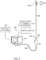
- the distal portion of the neuromodulation catheter 102 can optionally include an outlet 112 configured to provide an acute injection of a pharmacological agent that stimulates the vessel V or adjacent nerves to cause a hemodynamic response (e.g., vasodilation).
- the outlet 112 is positioned proximal to the electrodes 110 so that the pharmacological agent can flow distally through the vessel toward the electrodes 110 after injection, but in other embodiments the outlet 112 can be positioned elsewhere along the catheter 102 (e.g., between electrodes 110 or distal to the electrodes).
- the outlet 112 can be in fluid communication with a lumen 116 that extends through the neuromodulation catheter 102 and connects to a reservoir (not shown) of the pharmacological agent.
- Suitable pharmacological agents can include vasodilators, such as adenosine, bradykinin, and/or papaverine.
- the controller 104 can be configured to automatically inject the pharmacological agent via the outlet 112 before and after neuromodulation energy is applied, and one or more of the electrodes 110 can be used to measure the change in vessel impedance or vessel diameter.
- a clinician can manually inject the pharmacological agent.
- the pharmacological stimulus can be delivered proximate to the treatment site using other suitable means.
- a separate catheter can be used to inject the pharmacological agent, or the pharmacological agent can be injected via a needle into the vessel lumen, directly into the vessel wall, and/or into the surrounding tissue to target neural pathways. Similar to the electrical stimulus, the pharmacological stimulus causes a hemodynamic response (e.g., vessel dilation) that can be measured before and after the neuromodulation energy is applied and used to assess the efficacy of the neuromodulation treatment.
- a hemodynamic response e.g., vessel dilation
- the neuromodulation catheter 102 can also include at least one sensor 114 (shown schematically) and/or other device configured to detect a hemodynamic response to assess the efficacy of a neuromodulation therapy.
- the sensor 114 can be a flow sensor, such as a Doppler velocity sensor or an ultrasonic flow meter, that can detect blood flow through the vessel V in response to the pre- and post-neuromodulation stimuli.
- the sensor 114 can be a pressure sensor that measures changes in pressure within the vessel V in response to the pre- and post-neuromodulation stimuli.
- the catheter 102 can further include a fluid-filled lumen (not shown) extending along a length of the catheter 102 and open to the vessel V, and the lumen can be coupled to a pressure transducer (not shown) that measures the pressure within the vessel V.
- a pressure transducer not shown
- Similar to vessel diameter, blood flow and vessel pressure are expected to change in response to a stimulus, and these changes are expected to occur to at least a lesser degree after neuromodulation than before neuromodulation. Therefore, the changes in blood flow and/or vessel pressure measurements caused by an electrical or pharmacological stimulus can be detected before and after neuromodulation and then compared to a threshold value to determine the efficacy of neuromodulation therapy.
- the system 100 can include additional features that measure hemodynamic responses.
- FIG. 2 is a block diagram illustrating a method 200 of evaluating neuromodulation therapy in accordance with an embodiment of the present technology.
- the method 200 can be implemented using the system 100 described above with reference to FIGS. 1A and 1B and/or other suitable systems for evaluating the efficacy of neuromodulation therapy.
- the controller 104 and/or the catheter 102 can be used to perform the various steps of the method 200.
- the method 200 includes measuring an initial baseline impedance (Zb 1 ) of a vessel (block 205). For example, as discussed with respect to FIG.
- a distal portion of a catheter can be positioned along within a vessel, and one or more electrodes on the catheter can be used to detect the initial pre-neuromodulation impedance (Zb 1 ) of the vessel.
- Stimulation can then be delivered at or near the target site (block 210), and the resultant post-stimulation baseline vessel impedance (Zb 2 ) can be measured (block 215).
- the stimulation can be electrical in nature and applied via one or more electrodes at the distal portion of the catheter. In other embodiments, however, the stimulation can be pharmacological and applied via an acute injection of a drug (e.g., a vasodilator) into the vessel or vessel wall.
- the post-stimulation baseline impedance (Zb 2 ) can be measured in a similar manner to the initial baseline impedance (Zb 1 ).
- the method 200 continues by determining a change in the baseline impedance (AZb), which is the difference of the initial baseline impedance (Zb 1 ) and the post-stimulation baseline impedance (Zb 2 ) (block 220).
- a controller can record the impedance measurements and include instructions to determine the baseline change in impedance ( ⁇ Zb).
- the initial and post-stimulation baseline impedance measurements (Zb 1 ) and (Zb 2 ) can be used to determine an initial baseline vessel diameter and a post-stimulation baseline vessel diameter, and the difference between the two diameters can be taken to determine a baseline change in vessel diameter.
- the method 200 further continues by performing neuromodulation at the target site to ablate nerves proximate to the vessel wall (block 225).
- the method 200 can include applying RF energy (e.g., via electrodes), pulsed electrical energy, microwave energy, optical energy, ultrasound energy (e.g., intravascularly delivered ultrasound, extracorporeal ultrasound, and/or HIFU), direct heat energy, radiation, cryogenic cooling, chemical-based treatment, and/or another suitable type of neuromodulation energy.
- the neuromodulation can be applied using the same catheter as is used for applying stimulation and measuring impedance, or a second catheter or other device can be used to perform neuromodulation.
- the method 200 measures post-neuromodulation vessel impedance (Zn 1 ) after neuromodulation has been applied (block 230), delivers stimulation (e.g., electrical and/or pharmacological) at or proximate to the target site (block 235), and measures post-stimulation, post-neuromodulation impedance (Zn 2 ) resulting from the stimulus (block 240).
- the controller and/or another device can then determine the difference between the post-neuromodulation, pre-stimulation impedance (Zn 1 ) and the post-neuromodulation, post-stimulation impedance (Zn 2 ) to provide a post-neuromodulation change in impedance ( ⁇ Zn) (block 245).
- the controller and/or another device can convert the two recorded post-neuromodulation impedances to vessel diameters, and calculate a difference between the two vessel diameters.
- the method 200 can continue by comparing the difference of the baseline and post-neuromodulation vessel impedances ( ⁇ Zb - ⁇ Zn) or vessel diameters to a predetermined threshold value indicative of a desired level of neuromodulation (decision block 250).
- the threshold may be equivalent to a percentage decrease in the change in vessel impedance/diameter or another predetermined value.
- the method 200 does not measure the impedance values before each stimulus, and instead only measures the pre- and post-neuromodulation vessel impedances measured after each stimulus.
- the pre- and post-neuromodulation impedance values rather than the changes in these values, can be compared to each other to determine the efficacy of the neuromodulation therapy.
- the neuromodulation therapy is considered successful or effective, and the method 200 can end (block 250). However, if the difference between the pre- and post-neuromodulation vessel impedances/diameters is less than the predetermined threshold, the method 200 can continue by applying another round of neuromodulation energy to the treatment site (block 225).
- the second application of neuromodulation energy can be the equivalent in intensity and duration as the previous application of neuromodulation energy, or it can be increased in intensity or duration to increase the likelihood of effective neuromodulation.
- the change in post-neuromodulation vessel impedance/diameter can again be determined after the second application of neuromodulation energy as set forth in blocks 230-245.
- This change in post-neuromodulation vessel impedance/diameter can subsequently be compared to the predetermined threshold value (decision block 250) to determine whether the second application of neuromodulation energy was effective.
- These steps (blocks 230-250) can continue until the post-neuromodulation vessel impedances/diameter is at least equal to the predetermined threshold.
- the comparison of the pre- and post-neuromodulation vessel impedances/diameters to the threshold value can be performed automatically (e.g., by a controller), or the values can be provided to the clinician to assess the efficacy of the treatment.
- a clinician may opt to reposition the catheter within the vessel to select another target site at which to apply neuromodulation energy. For example, if the first target site within the vessel did not result in adequate neuromodulation after one or more energy applications, the clinician may reposition the catheter proximally or distally along the length of the vessel to locate a site that may be better suited for neuromodulation (e.g., because the nerves are closer to the vessel). Alternatively or in addition, the clinician may relocate the catheter within the vessel after a successful neuromodulation therapy at the first target site to create a second target site, and ablate additional nerves. When the clinician repositions the catheter, the method 200 can be repeated from the beginning (i.e., block 205) so that the baseline vessel impedance/diameter is specific to the new target site.
- FIG. 3 is a partially schematic side view of a system 300 for evaluating neuromodulation therapy (“system 300") configured in accordance with another embodiment of the present technology.
- the system 300 includes a first catheter 302a and a second catheter 302b (collectively referred to as "catheters 302") communicatively coupled to a controller 304 via a wired or wireless connection.
- Each catheter 302 can include an elongated shaft (identified individually as a first shaft 306a and a second shaft 306b, and referred to collectively as shafts 306) having a distal portion (identified individually as a first distal portion 308a and a second distal portion 308b, and referred to collectively as distal portions 308) and a proximal portion (identified individually as a first proximal portion 312a and a second proximal portion 312b, and referred to collectively as the proximal portions 312).
- each shaft 306 can carry at least one energy delivery element, such as an electrode (identified individually as a first electrode 310a and a second electrode 310b, and referred to collectively as electrodes 310).
- an electrode identified individually as a first electrode 310a and a second electrode 310b, and referred to collectively as electrodes 310.
- each catheter 302 includes a single electrode 310, but in other embodiments one or both of the catheters 302 may include more than one electrode 310.
- the first and second catheters 302a and 302b can be advanced through the vena cava VC and the abdominal aorta A, respectively, such that the distal portions 308 of the catheters 302 are positioned within or proximate to a renal vein RV and renal artery RA, respectively, of a patient.
- the first distal portion 308a of the first catheter 302a is positioned proximate to the ostium of the renal vein RV
- the second distal portion 308b of the second catheter 302b is positioned proximate to the ostium of the renal artery RA.
- the distal portions 308 of the first and second catheters 302a and 302b are positioned completely within the renal vein RV and renal artery RA.
- the system 300 can be configured to measure the impedance across the renal vein RV and the renal artery RA before and after neuromodulation therapy to assess the efficacy of the neuromodulation therapy.
- the first and second electrodes 310a and 310b can apply a stimulus across the renal vein RV and the renal artery RA, and then the same first and second electrodes 310a and 310b can be used to detect a baseline, pre-neuromodulation impedance across the renal artery and vein RA and RV resulting from the stimulus.
- the catheters 302 can include multiple electrodes with at least one electrode designated to apply stimuli and at least another electrode designated to measure impedance.
- the catheters 302 can be configured to apply pharmacological stimuli (e.g., similar to the catheter 102 of FIGS. 1A and 1B ).
- the baseline, pre-neuromodulation impedance value represents the impedance across the renal perfusion bed before neuromodulation. That is, when impedance is taken across the renal artery RA and the renal vein RV, the impedance measurement is influenced, in large part, by the amount of blood perfusing the kidney because the measured field includes a low impedance path that extends from the renal artery RA, through the vasculature of the kidney, to the renal vein RV.
- the baseline, pre-neuromodulation impedance is equivalent to the difference between the impedances measured before and after stimulation.
- neuromodulation energy can be applied to a target site within the renal artery RA and/or renal vein RV. Similar to the application of neuromodulation energy described above, neuromodulation can be provided in the form of RF energy, pulsed energy, microwave energy, optical energy, ultrasound energy (e.g., intravascularly delivered ultrasound, extracorporeal ultrasound, and/or HIFU), direct heat energy, radiation, cryogenic cooling, chemical-based treatment, and/or another suitable type of neuromodulation means.
- the second electrode 310b of the second catheter 302b can be used to apply neuromodulation energy (e.g., RF energy) to one or more target sites within the renal artery RA.
- first distal portion 308a of the first catheter 302a and/or the second distal portion 308b of the second catheter 302b can include multiple electrodes (e.g., similar to the spiral/helical catheter 102 illustrated in FIG. 1B ) that deliver neuromodulation energy to one or more target sites.
- the first and second electrodes 310a and 310b can apply a stimulus across the renal vein RV and the renal artery RA, and then the same first and second electrodes 310a and 310b can detect the resultant post-neuromodulation impedance across the renal artery RA and renal vein RV.
- the post-neuromodulation impedance is determined by taking the difference between (1) the impedance measured after neuromodulation, but before stimulation, and (2) the impedance measured after neuromodulation and after stimulation.
- the controller 304 can compare the baseline, pre-neuromodulation impedance value with the post-neuromodulation impedance value to a predetermined threshold that is indicative of successful ablation.
- the threshold value may be a predetermined decrease in the impedance value (e.g., 10%, 20%, 30%, 40%, etc. less than the pre-neuromodulation impedance value) and/or another suitable value associated with effective neuromodulation.
- the neuromodulation therapy may be deemed successful in ablating nerves to the desired degree, whereas if the difference is less than a predetermined threshold, the clinician may opt to apply additional rounds of neuromodulation energy at the treatment site or at another treatment site along the vessel. Accordingly, like the system 100 described above with reference to FIGS. 1A and 1B , the system 300 of FIG. 3 can provide a user with feedback as to the effectiveness of neuromodulation therapy.
- the system 300 can provide feedback to clinicians regarding the efficacy of neuromodulation treatments in substantially real time, and therefore allows clinicians to apply additional rounds of neuromodulation therapy without needing to reinsert the neuromodulation catheter(s) 302 into the patient.
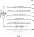
- FIG. 4 is a block diagram illustrating a method 400 of determining a treatment site within a blood vessel in accordance with an embodiment of the present technology.
- the method 400 can be performed using the systems 100 and 300 described above with respect to FIGS. 1A, 1B , and 3 , or using other suitable systems.
- the method 400 can begin by applying a first stimulus at the treatment site (block 405), and measuring a first hemodynamic response (H 1 ) to the first stimulus (block 410).
- the first stimulus can be an electrical stimulus and/or a pharmacological stimulus sufficient to stimulate nerves proximate to a treatment site.
- an electrical stimulus can be applied via one or more electrodes at a distal portion of a catheter positioned proximate to or within a vessel, such as a renal artery.
- the electrode(s) may contact the vessel wall when delivering the stimulus, or the electrode(s) may be spaced apart from the vessel wall (e.g., as shown in FIG. 1A ).
- a catheter can deliver a pharmacological agent into the vessel or inject the pharmacological agent into the vessel wall to acutely stimulate nerves proximate to the vessel.
- the first hemodynamic response (H 1 ) can correspond to blood flow through the vessel, pressure within the vessel, vessel impedance, vessel diameter, impedance across a perfusion bed (e.g., across the renal artery and renal vein), and/or other hemodynamic parameters affected by stimuli.
- the first hemodynamic response (H 1 ) can refer to a hemodynamic parameter derived from the difference between a baseline, pre-stimulus hemodynamic measurement and a post-stimulus hemodynamic measurement. In other embodiments, the first hemodynamic response can simply refer to the measured response to the first stimulus.
- the first hemodynamic response (H 1 ) can be measured via sensors, electrodes, and/or other features at the distal portion of the catheter.
- the catheter can include a blood flow sensor to determine the blood flow within the vessel in response to the first stimulus and/or a pressure sensor to detect pressure within the vessel in response to the first stimulus.
- the method 400 can continue by temporarily stunning nerves at the treatment site (block 415).
- Temporarily stunning nerves can refer to temporarily preventing neural transmission or depolarization without permanent damage to the nerve.
- nerves can be temporarily stunned by applying cryogenic cooling cold enough to stop neural transmission without permanent damage. This can be performed using a cryo-catheter at higher output temperatures and/or shorter lengths of time than the parameters used to create a lesion and/or permanently modulate nerves.
- the nerves can be temporarily stunned by applying heat or electrical stimulation (e.g., via electrodes) to a vessel wall.
- nerves can be temporarily stunned by applying RF energy to a vessel wall with electrodes positioned on a distal portion of a catheter (e.g., the helical catheter 102 illustrated in FIG. 1B ). Accordingly, nerves can be temporarily stunned by applying higher energy or more cooling than required for the stimuli that evoke a hemodynamic response, but less energy or cooling than necessary to permanently modulate nerves.
- a second stimulus can be applied at the treatment site (block 420), and a second hemodynamic response (H 2 ) to the second stimulus can be measured (block 425).
- the second hemodynamic response (H 2 ) can refer to a change in a hemodynamic parameter derived from the difference between a post-stunning, pre-stimulus hemodynamic parameter and a post-stunning, post-stimulus hemodynamic parameter, or to the hemodynamic parameter detected in response to the second stimulus.
- the first hemodynamic response (H 1 ) is expected to be higher than the second hemodynamic response (H 2 ) because the stunned nerves do not respond to the second stimulus, or at least not to the same extent as the nerves prior to stunning.
- the first hemodynamic response (H 1 ) is expected to be higher than the second hemodynamic response (H 2 ) when the stimuli causes vasoconstriction (e.g., electrical stimuli), and lower than the second hemodynamic response (H 2 ) when the stimuli cause vasodilation (e.g., pharmacological stimuli).
- vasoconstriction e.g., electrical stimuli
- H 2 the stimuli cause vasodilation
- the difference between the first and second hemodynamic responses (H 1 -H 2 ) can be compared to a predetermined threshold value indicative of a suitable site for neuromodulation (decision block 430).
- the threshold value may correlate to a predetermined change in the hemodynamic response or a percentage decrease in the hemodynamic response.
- any decrease in the hemodynamic responses taken before and after temporary stunning may indicate that there are nerves proximate to the site that was temporarily stunned, and therefore it may be a suitable location for neuromodulation. Accordingly, if the difference between the first and second hemodynamic responses is above the threshold value, the method 400 continues by performing neuromodulation at the same site where the nerves were temporarily stunned (block 435).
- a controller can provide signals to the catheter to automatically apply stimuli, record resultant hemodynamic responses, and apply energy to temporarily stun nerves.
- the controller may also be configured to automatically compare the hemodynamic responses and provide the clinician with feedback as to whether the predetermined threshold is met.
- the method 400 can therefore be used before neuromodulation therapies to detect locations within a vessel with sufficient neural activity to allow for effective neuromodulation therapy.
- FIG. 5 is a block diagram illustrating a method 500 of evaluating neuromodulation therapy at individual ablation sites in accordance with an embodiment of the present technology.
- the method 500 can be performed using the system 100 described above with reference to FIGS. 1A and 1B and/or other suitable systems for evaluation neuromodulation therapy.
- the method 500 includes applying a first stimulation across an ablation or treatment site (block 505), and measuring a first hemodynamic response (H 1 ) across the ablation site (block 510).
- the first hemodynamic response (H 1 ) can refer to a hemodynamic parameter detected in response to the first stimulus, or a change in a hemodynamic parameter derived from the difference between a pre-stimulus hemodynamic parameter and a post-stimulus hemodynamic parameter.
- the stimulus is applied locally to a specific ablation site, rather than globally across multiple ablation sites or along a larger length of a vessel. Accordingly, the stimulation applied may have a smaller amplitude than those stimulation pulses used to test global success of denervation (e.g., across an entire treatment site or along a larger portion of a vessel).
- an electrical stimulus can be applied via electrodes on either side of the ablation site, and the hemodynamic response (e.g., blood flow, pressure, impedance, etc.) resulting from the local stimulation can be measured at or proximate to the ablation site.
- the method 500 can continue by performing neuromodulation at the ablation site (block 515).
- the neuromodulation can be applied using the various forms of energy described above (e.g., RF energy), cryogenic cooling, and/or chemical-based treatment.
- a second stimulation can be applied across the ablation site (block 520), and a second hemodynamic response (H 2 ) can be measured across the ablation site (block 525).
- the second hemodynamic response (H 2 ) can refer to a hemodynamic parameter detected in response to the second stimulus, or a change in a hemodynamic parameter derived from the difference between a post-neuromodulation, pre-stimulus hemodynamic parameter and a post-neuromodulation, post-stimulus hemodynamic parameter.
- the difference between the first and second hemodynamic responses can be compared to a predetermined threshold (decision block 530).
- the predetermined threshold can be equal to a value indicative of successful neuromodulation across the ablation site. If the difference in the hemodynamic responses is lower than the predetermined threshold, the method can continue by reapplying neuromodulation energy across the ablation site and measuring the resultant hemodynamic response until it is higher than the threshold.
- the method 500 can continue by repositioning the catheter to a new ablation site 535 and repeating the method 500 at the new ablation site. The method 500 can be repeated until the clinician has performed neuromodulation at a desired number of ablation site.
- the method 500 can be used to determine the effectiveness of neuromodulation across a specific ablation site. That is, the method 500 tests whether there is any neural tissue near an ablation site that will conduct a signal in response to a stimulus and evoke a hemodynamic response (e.g., pressure, blood flow, vessel diameter, etc.). If local stimulation indicates that the neuromodulation has been ineffective (i.e., block 530), then this information can be used by the clinician to apply additional rounds of neuromodulation therapy to the same ablation site to adequately modulate nerves at the ablation site.
- a hemodynamic response e.g., pressure, blood flow, vessel diameter, etc.
- FIG. 6 is a partially schematic illustration of a therapeutic system 600 ("system 600") configured in accordance with still another embodiment of the present technology.
- the system 600 can include various features similar to the systems 100 and 300 described above with respect to FIGS. 1A, 1B , and 3 , and may be used to implement the various methods 200, 400, and 500 described above.
- the system 600 includes a neuromodulation catheter 602, a console 604, and a cable 606 extending therebetween.
- the neuromodulation catheter 602 can include an elongated shaft 608 having a proximal portion 608b, a distal portion 608a, a handle 610 operably connected to the shaft 608 at the proximal portion 608b, and a neuromodulation assembly 620 operably connected to the shaft 608 at the distal portion 608a.
- the shaft 608 and the neuromodulation assembly 620 can be 2, 3, 4, 5, 6, or 7 French or another suitable size.
- the neuromodulation assembly 620 can include a support structure 622 carrying an array of two or more electrodes 624.
- the electrodes 624 can be configured to apply electrical stimuli (e.g., RF energy) to target sites at or proximate to vessels within a patient, temporarily stun nerves, deliver neuromodulation energy to target sites, and/or detect vessel impedance.
- electrical stimuli e.g., RF energy
- certain electrodes 624 can be dedicated to applying stimuli and/or detecting impedance
- the neuromodulation assembly 620 can include other types of therapeutic elements that provide neuromodulation therapy using various modalities, such cryotherapeutic cooling, ultrasound energy, etc.
- the distal portion 608a of the shaft 608 is configured to be moved within a lumen of a human patient and locate the neuromodulation assembly 620 at a target site within or otherwise proximate to the lumen.
- shaft 608 can be configured to position the neuromodulation assembly 620 within a blood vessel, a duct, an airway, or another naturally occurring lumen within the human body.
- intravascular delivery of the neuromodulation assembly 620 includes percutaneously inserting a guide wire (not shown) into a body lumen of a patient and moving the shaft 608 and/or the neuromodulation assembly 620 along the guide wire until the neuromodulation assembly 620 reaches a target site (e.g., a renal artery).
- a target site e.g., a renal artery
- the distal end of the neuromodulation assembly 620 may define a passageway for engaging the guide wire for delivery of the neuromodulation assembly 620 using over-the-wire (OTW) or rapid exchange (RX) techniques.
- OW over-the-wire
- RX rapid exchange
- the neuromodulation catheter 602 can be a steerable or non-steerable device configured for use without a guide wire.
- the neuromodulation catheter 602 can be configured for delivery via a guide catheter or sheath (not shown).
- the neuromodulation assembly 620 can be configured to apply stimuli, detect resultant hemodynamic responses, and provide or facilitate neuromodulation therapy at the target site (e.g., using the electrodes 624 and/or other energy delivery elements).
- the neuromodulation assembly 620 can detect vessel impedance via the electrodes 624, blood flow via a flow sensor (e.g., a Doppler velocity sensor), local blood pressure within the vessel via a pressure transducer or other pressure sensor, and/or other hemodynamic parameters.
- the detected hemodynamic responses can be transmitted to the console 604 and/or another device external to the patient.
- the console 604 can be configured to receive and store the recorded hemodynamic responses for further use by a clinician or operator. For example, a clinician can use the hemodynamic responses received by the console 604 to determine whether an application of neuromodulation energy was effective in modulating nerves to a desired degree.
- the console 604 can be configured to control, monitor, supply, and/or otherwise support operation of the neuromodulation catheter 602.
- the console 604 can further be configured to generate a selected form and/or magnitude of energy for delivery to tissue at the target site via the neuromodulation assembly 620, and therefore the console 604 may have different configurations depending on the treatment modality of the neuromodulation catheter 602.
- the console 604 can include an energy generator (not shown) configured to generate RF energy (e.g., monopolar and/or bipolar RF energy), pulsed electrical energy, microwave energy, optical energy, ultrasound energy (e.g., intravascularly delivered ultrasound, extracorporeal ultrasound, and/or HIFU), direct heat energy, radiation (e.g., infrared, visible, and/or gamma radiation), and/or another suitable type of energy.
- RF energy e.g., monopolar and/or bipolar RF energy
- pulsed electrical energy e.g., microwave energy, optical energy, ultrasound energy (e.g., intravascularly delivered ultrasound, extracorporeal ultrasound, and/or HIFU), direct heat energy, radiation (e.g., infrared, visible, and/or gamma radiation), and/or another suitable type of energy.
- RF energy e.g., monopolar and/or bipolar RF energy
- microwave energy e.g., microwave energy
- optical energy e.g.
- the console 604 can include a refrigerant reservoir (not shown), and can be configured to supply the neuromodulation catheter 602 with refrigerant.
- the console 604 can include a chemical reservoir (not shown) and can be configured to supply the neuromodulation catheter 602 with one or more chemicals.
- the system 600 may be configured to deliver a monopolar electric field via one or more of the electrodes 624.
- a neutral or dispersive electrode 630 may be electrically connected to the console 604 and attached to the exterior of the patient.
- the electrodes 624 may deliver power independently (i.e., may be used in a monopolar fashion), either simultaneously, selectively, or sequentially, and/or may deliver power between any desired combination of the electrodes 624 (i.e., may be used in a bipolar fashion).
- an operator optionally may be permitted to choose which electrodes 624 are used for power delivery in order to form highly customized lesion(s) within the renal artery, as desired.
- One or more sensors may be located proximate to, within, or integral with the electrodes 624.
- the sensor(s) and the electrodes 624 can be connected to one or more supply wires (not shown) that transmit signals from the sensors) and/or convey energy to the electrodes 624.
- the system 600 can further include a controller 614 communicatively coupled to the neuromodulation catheter 602.
- the controller 602 can be configured to initiate, terminate, and/or adjust operation of one or more components (e.g., the electrodes 624) of the neuromodulation catheter 602 directly and/or via the console 604.
- the controller 614 can be omitted or have other suitable locations (e.g., within the handle 610, along the cable 606, etc.).
- the controller 614 can be configured to execute an automated control algorithm and/or to receive control instructions from an operator.
- the console 604 can be configured to provide feedback to an operator before, during, and/or after a treatment procedure via an evaluation/feedback algorithm 616.
- FIG. 7 illustrates modulating renal nerves in accordance with an embodiment of the system 600.
- the neuromodulation catheter 602 provides access to the renal plexus RP through an intravascular path P, such as a percutaneous access site in the femoral (illustrated), brachial, radial, or axillary artery to a targeted treatment site within a respective renal artery RA.
- an intravascular path P such as a percutaneous access site in the femoral (illustrated), brachial, radial, or axillary artery to a targeted treatment site within a respective renal artery RA.
- a clinician may advance the shaft 608 through the sometimes tortuous intravascular path P and remotely manipulate the distal portion 608a ( FIG. 6 ) of the shaft 608.
- FIG. 6 illustrates modulating renal nerves in accordance with an embodiment of the system 600.
- the neuromodulation assembly 620 is delivered intravascularly to the treatment site using a guide wire 636 in an OTW technique.
- the distal end of the neuromodulation assembly 620 may define a passageway for receiving the guide wire 636 for delivery of the neuromodulation catheter 602 using either OTW or RX techniques.
- the guide wire 636 can be at least partially withdrawn or removed, and the neuromodulation assembly 620 can transform or otherwise be moved to a deployed arrangement for recording neural activity and/or delivering energy at the treatment site.
- the neuromodulation assembly 620 may be delivered to the treatment site within a guide sheath (not shown) with or without using the guide wire 636.
- the guide sheath When the neuromodulation assembly 620 is at the target site, the guide sheath may be at least partially withdrawn or retracted and the neuromodulation assembly 620 can be transformed into the deployed arrangement.
- the shaft 608 may be steerable itself such that the neuromodulation assembly 620 may be delivered to the treatment site without the aid of the guide wire 636 and/or guide sheath.
- Image guidance e.g., computed tomography (CT), fluoroscopy, intravascular ultrasound (IVUS), optical coherence tomography (OCT), intracardiac echocardiography (ICE), or another suitable guidance modality, or combinations thereof, may be used to aid the clinician's positioning and manipulation of the neuromodulation assembly 620.
- a fluoroscopy system e.g., including a flat-panel detector, x-ray, or c-arm
- the treatment site can be determined using IVUS, OCT, and/or other suitable image mapping modalities that can correlate the target treatment site with an identifiable anatomical structure (e.g., a spinal feature) and/or a radiopaque ruler (e.g., positioned under or on the patient) before delivering the neuromodulation assembly 620.
- image guidance components e.g., IVUS, OCT
- image guidance components e.g., IVUS or OCT
- the neuromodulation assembly 620 can be coupled to the neuromodulation assembly 620 to provide three-dimensional images of the vasculature proximate the target site to facilitate positioning or deploying the multi-electrode assembly within the target renal blood vessel.
- Energy from the electrodes 624 ( FIG. 6 ) and/or other energy delivery elements may then be applied to target tissue to induce one or more desired neuromodulating effects on localized regions of the renal artery RA and adjacent regions of the renal plexus RP, which lay intimately within, adjacent to, or in close proximity to the adventitia of the renal artery RA.
- the purposeful application of the energy may achieve neuromodulation along all or at least a portion of the renal plexus RP.
- the neuromodulating effects are generally a function of, at least in part, power, time, contact between the energy delivery elements and the vessel wall, and blood flow through the vessel.
- the neuromodulating effects may include denervation, thermal ablation, and/or non-ablative thermal alteration or damage (e.g., via sustained heating and/or resistive heating).
- Desired thermal heating effects may include raising the temperature of target neural fibers above a desired threshold to achieve non-ablative thermal alteration, or above a higher temperature to achieve ablative thermal alteration.
- the target temperature may be above body temperature (e.g., approximately 37°C) but less than about 45°C for non-ablative thermal alteration, or the target temperature may be about 45°C or higher for the ablative thermal alteration.
- Desired non-thermal neuromodulation effects may include altering the electrical signals transmitted in a nerve.
- hypothermic effects may also provide neuromodulation.
- a cryotherapeutic applicator may be used to cool tissue at a target site to provide therapeutically-eftective direct cell injury (e.g., necrosis), vascular injury (e.g., starving the cell from nutrients by damaging supplying blood vessels), and sublethal hypothermia with subsequent apoptosis.
- Exposure to cryotherapeutic cooling can cause acute cell death (e.g., immediately after exposure) and/or delayed cell death (e.g., during tissue thawing and subsequent hyperperfusion).
- Embodiments of the present technology can include cooling a structure at or near an inner surface of a renal artery wall such that proximate (e.g., adjacent) tissue is effectively cooled to a depth where sympathetic renal nerves reside.
- the cooling structure is cooled to the extent that it causes therapeutically effective, cryogenic renal-nerve modulation.
- Sufficiently cooling at least a portion of a sympathetic renal nerve is expected to slow or potentially block conduction of neural signals to produce a prolonged or permanent reduction in renal sympathetic activity.
- the electrodes 624 and/or other features of the neuromodulation assembly 620 can intravascularly apply stimuli to the renal artery RA and detect hemodynamic responses to the stimuli before and/or after neuromodulation energy is applied to the renal artery RA. This information can then be used to determine the efficacy of the neuromodulation therapy.
- the controller 614 FIG. 6
- the controller 614 can process the detected hemodynamic responses before and after neuromodulation and compare the change in hemodynamic response to a predetermined threshold to assess whether neuromodulation therapy was effective across the treatment site or at a specific ablation site.
- Renal neuromodulation is the partial or complete incapacitation or other effective disruption of nerves of the kidneys (e.g., nerves terminating in the kidneys or in structures closely associated with the kidneys).
- renal neuromodulation can include inhibiting, reducing, and/or blocking neural communication along neural fibers (e.g., efferent and/or afferent neural fibers) of the kidneys.
- Such incapacitation can be long-term (e.g., permanent or for periods of months, years, or decades) or short-term (e.g., for periods of minutes, hours, days, or weeks).
- Renal neuromodulation is expected to contribute to the systemic reduction of sympathetic tone or drive and/or to benefit at least some specific organs and/or other bodily structures innervated by sympathetic nerves. Accordingly, renal neuromodulation is expected to be useful in treating clinical conditions associated with systemic sympathetic overactivity or hyperactivity, particularly conditions associated with central sympathetic overstimulation. For example, renal neuromodulation is expected to efficaciously treat hypertension, heart failure, acute myocardial infarction, metabolic syndrome, insulin resistance, diabetes, left ventricular hypertrophy, chronic and end stage renal disease, inappropriate fluid retention in heart failure, cardio-renal syndrome, polycystic kidney disease, polycystic ovary syndrome, osteoporosis, erectile dysfunction, and sudden death, among other conditions.
- Renal neuromodulation can be electrically-induced, thermally-induced, chemically-induced, or induced in another suitable manner or combination of manners at one or more suitable target sites during a treatment procedure.
- the target site can be within or otherwise proximate to a renal lumen (e.g., a renal artery, a ureter, a renal pelvis, a major renal calyx, a minor renal calyx, or another suitable structure), and the treated tissue can include tissue at least proximate to a wall of the renal lumen.
- a treatment procedure can include modulating nerves in the renal plexus, which lay intimately within or adjacent to the adventitia of the renal artery.
- Renal neuromodulation can include a cryotherapeutic treatment modality alone or in combination with another treatment modality.
- Cryotherapeutic treatment can include cooling tissue at a target site in a manner that modulates neural function.
- sufficiently cooling at least a portion of a sympathetic renal nerve can slow or potentially block conduction of neural signals to produce a prolonged or permanent reduction in renal sympathetic activity.
- cryotherapeutic tissue damage can include, for example, direct cell injury (e.g., necrosis), vascular or luminal injury (e.g., starving cells from nutrients by damaging supplying blood vessels), and/or sublethal hypothermia with subsequent apoptosis.
- Exposure to cryotherapeutic cooling can cause acute cell death (e.g., immediately after exposure) and/or delayed cell death (e.g., during tissue thawing and subsequent hyperperfusion).
- Neuromodulation using a cryotherapeutic treatment in accordance with embodiments of the present technology can include cooling a structure proximate an inner surface of a body lumen wall such that tissue is effectively cooled to a depth where sympathetic renal nerves reside.
- a cooling assembly of a cryotherapeutic device can be cooled to the extent that it causes therapeutically-effective, cryogenic renal neuromodulation.
- a cryotherapeutic treatment modality can include cooling that is not configured to cause neuromodulation.
- the cooling can be at or above cryogenic temperatures and can be used to control neuromodulation via another treatment modality (e.g., to protect tissue from neuromodulating energy).
- Renal neuromodulation can include an electrode-based or transducer-based treatment modality alone or in combination with another treatment modality.
- Electrode-based or transducer-based treatment can include delivering electricity and/or another form of energy to tissue at a treatment location to stimulate and/or heat the tissue in a manner that modulates neural function. For example, sufficiently stimulating and/or heating at least a portion of a sympathetic renal nerve can slow or potentially block conduction of neural signals to produce a prolonged or permanent reduction in renal sympathetic activity.
- a variety of suitable types of energy can be used to stimulate and/or heat tissue at a treatment location.
- neuromodulation in accordance with embodiments of the present technology can include delivering RF energy, pulsed electrical energy, microwave energy, optical energy, focused ultrasound energy (e.g., high-intensity focused ultrasound energy), or another suitable type of energy alone or in combination.
- An electrode or transducer used to deliver this energy can be used alone or with other electrodes or transducers in a multi-electrode or multi-transducer array.
- the energy can be applied from within the body (e.g., within the vasculature or other body lumens in a catheter-based approach) and/or from outside the body (e.g., via an applicator positioned outside the body).
- energy can be used to reduce damage to non-targeted tissue when targeted tissue adjacent to the non-targeted tissue is subjected to neuromodulating cooling.
- Focused ultrasound is an example of a transducer-based treatment modality that can be delivered from outside the body. Focused ultrasound treatment can be performed in close association with imaging (e.g., magnetic resonance, computed tomography, fluoroscopy, ultrasound (e.g., intravascular or intraluminal), optical coherence tomography, or another suitable imaging modality). For example, imaging can be used to identify an anatomical position of a treatment location (e.g., as a set of coordinates relative to a reference point).
- imaging can be used to identify an anatomical position of a treatment location (e.g., as a set of coordinates relative to a reference point).
- the coordinates can then entered into a focused ultrasound device configured to change the power, angle, phase, or other suitable parameters to generate an ultrasound focal zone at the location corresponding to the coordinates.
- the focal zone can be small enough to localize therapeutically-effective heating at the treatment location while partially or fully avoiding potentially harmful disruption of nearby structures.
- the ultrasound device can be configured to pass ultrasound energy through a lens, and/or the ultrasound energy can be generated by a curved transducer or by multiple transducers in a phased array (curved or straight).
- Heating effects of electrode-based or transducer-based treatment can include ablation and/or non-ablative alteration or damage (e.g., via sustained heating and/or resistive heating).
- a treatment procedure can include raising the temperature of target neural fibers to a target temperature above a first threshold to achieve non-ablative alteration, or above a second, higher threshold to achieve ablation.
- the target temperature can be higher than about body temperature (e.g., about 37°C) but less than about 45°C for non-ablative alteration, and the target temperature can be higher than about 45°C for ablation.
- Heating tissue to a temperature between about body temperature and about 45°C can induce non-ablative alteration, for example, via moderate heating of target neural fibers or of vascular or luminal structures that perfuse the target neural fibers. In cases where vascular structures are affected, the target neural fibers can be denied perfusion resulting in necrosis of the neural tissue. Heating tissue to a target temperature higher than about 45°C (e.g., higher than about 60°C) can induce ablation, for example, via substantial heating of target neural fibers or of vascular or luminal structures that perfuse the target fibers.
- tissue it can be desirable to heat tissue to temperatures that are sufficient to ablate the target neural fibers or the vascular or luminal structures, but that are less than about 90°C (e.g., less than about 85°C, less than about 80°C, or less than about 75°C).
- Renal neuromodulation can include a chemical-based treatment modality alone or in combination with another treatment modality.
- Neuromodulation using chemical-based treatment can include delivering one or more chemicals (e.g., drugs or other agents) to tissue at a treatment location in a manner that modulates neural function.
- the chemical for example, can be selected to affect the treatment location generally or to selectively affect some structures at the treatment location over other structures.
- the chemical for example, can be guanethidine, ethanol, phenol, a neurotoxin, or another suitable agent selected to alter, damage, or disrupt nerves.
- a variety of suitable techniques can be used to deliver chemicals to tissue at a treatment location.
- chemicals can be delivered via one or more needles originating outside the body or within the vasculature or other body lumens.
- a catheter can be used to intravascularly position a therapeutic element including a plurality of needles (e.g., micro-needles) that can be retracted or otherwise blocked prior to deployment
- a chemical can be introduced into tissue at a treatment location via simple diffusion through a body lumen wall, electrophoresis, or another suitable mechanism. Similar techniques can be used to introduce chemicals that are not configured to cause neuromodulation, but rather to facilitate neuromodulation via another treatment modality.
- the sympathetic nervous system is a branch of the autonomic nervous system along with the enteric nervous system and parasympathetic nervous system. It is always active at a basal level (called sympathetic tone) and becomes more active during times of stress.
- the sympathetic nervous system operates through a series of interconnected neurons. Sympathetic neurons are frequently considered part of the peripheral nervous system (PNS), although many lie within the central nervous system (CNS).
- Sympathetic neurons of the spinal cord (which is part of the CNS) communicate with peripheral sympathetic neurons via a series of sympathetic ganglia. Within the ganglia, spinal cord sympathetic neurons join peripheral sympathetic neurons through synapses. Spinal cord sympathetic neurons are therefore called presynaptic (or preganglionic) neurons, while peripheral sympathetic neurons are called postsynaptic (or postganglionic) neurons.
- preganglionic sympathetic neurons release acetylcholine, a chemical messenger that binds and activates nicotinic acetylcholine receptors on postganglionic neurons.
- postganglionic neurons principally release noradrenaline (norepinephrine). Prolonged activation may elicit the release of adrenaline from the adrenal medulla.
- norepinephrine and epinephrine bind adrenergic receptors on peripheral tissues. Binding to adrenergic receptors causes a neuronal and hormonal response. The physiologic manifestations include pupil dilation, increased heart rate, occasional vomiting, and increased blood pressure. Increased sweating is also seen due to binding of cholinergic receptors of the sweat glands.
- the sympathetic nervous system is responsible for up- and down-regulating many homeostatic mechanisms in living organisms. Fibers from the SNS innervate tissues in almost every organ system, providing at least some regulatory function to physiological features as diverse as pupil diameter, gut motility, and urinary output. This response is also known as sympatho-adrenal response of the body, as the preganglionic sympathetic fibers that end in the adrenal medulla (but also all other sympathetic fibers) secrete acetylcholine, which activates the secretion of adrenaline (epinephrine) and to a lesser extent noradrenaline (norepinephrine). Therefore, this response that acts primarily on the cardiovascular system is mediated directly via impulses transmitted through the sympathetic nervous system and indirectly via catecholamines secreted from the adrenal medulla.
- the SNS provides a network of nerves that allows the brain to communicate with the body.
- Sympathetic nerves originate inside the vertebral column, toward the middle of the spinal cord in the intermediolateral cell column (or lateral horn), beginning at the first thoracic segment of the spinal cord and are thought to extend to the second or third lumbar segments. Because its cells begin in the thoracic and lumbar regions of the spinal cord, the SNS is said to have a thoracolumbar outflow. Axons of these nerves leave the spinal cord through the anterior rootlet/root. They pass near the spinal (sensory) ganglion, where they enter the anterior rami of the spinal nerves.
- the axons In order to reach the target organs and glands, the axons should travel long distances in the body, and, to accomplish this, many axons relay their message to a second cell through synaptic transmission. The ends of the axons link across a space, the synapse, to the dendrites of the second cell. The first cell (the presynaptic cell) sends a neurotransmitter across the synaptic cleft where it activates the second cell (the postsynaptic cell). The message is then carried to the final destination.
- ganglia In the SNS and other components of the peripheral nervous system, these synapses are made at sites called ganglia, discussed above.
- the cell that sends its fiber is called a preganglionic cell, while the cell whose fiber leaves the ganglion is called a postganglionic cell.
- the preganglionic cells of the SNS are located between the first thoracic (T1) segment and third lumbar (L3) segments of the spinal cord.
- Postganglionic cells have their cell bodies in the ganglia and send their axons to target organs or glands.
- the ganglia include not just the sympathetic trunks but also the cervical ganglia (superior, middle and inferior), which sends sympathetic nerve fibers to the head and thorax organs, and the celiac and mesenteric ganglia (which send sympathetic fibers to the gut).
- the kidney is innervated by the renal plexus (RP), which is intimately associated with the renal artery.
- the renal plexus (RP) is an autonomic plexus that surrounds the renal artery and is embedded within the adventitia of the renal artery.
- the renal plexus (RP) extends along the renal artery until it arrives at the substance of the kidney. Fibers contributing to the renal plexus (RP) arise from the celiac ganglion, the superior mesenteric ganglion, the aorticorenal ganglion and the aortic plexus.
- the renal plexus (RP) also referred to as the renal nerve, is predominantly comprised of sympathetic components. There is no (or at least very minimal) parasympathetic innervation of the kidney.
- Preganglionic neuronal cell bodies are located in the intermediolateral cell column of the spinal cord. Preganglionic axons pass through the paravertebral ganglia (they do not synapse) to become the lesser splanchnic nerve, the least splanchnic nerve, first lumbar splanchnic nerve, second lumbar splanchnic nerve, and travel to the celiac ganglion, the superior mesenteric ganglion, and the aorticorenal ganglion. Postganglionic neuronal cell bodies exit the celiac ganglion, the superior mesenteric ganglion, and the aorticorenal ganglion to the renal plexus (RP) and are distributed to the renal vasculature.
- RP renal plexus
- Efferent messages may trigger changes in different parts of the body simultaneously.
- the sympathetic nervous system may accelerate heart rate; widen bronchial passages; decrease motility (movement) of the large intestine; constrict blood vessels; increase peristalsis in the esophagus; cause pupil dilation, piloerection (goose bumps) and perspiration (sweating); and raise blood pressure.
- Afferent messages carry signals from various organs and sensory receptors in the body to other organs and, particularly, the brain.
- renin-angiotensin-aldosterone system has been a longstanding, but somewhat ineffective, approach for reducing over-activity of the SNS.
- the renal sympathetic nervous system has been identified as a major contributor to the complex pathophysiology of hypertension, states of volume overload (such as heart failure), and progressive renal disease, both experimentally and in humans.
- Studies employing radiotracer dilution methodology to measure overflow of norepinephrine from the kidneys to plasma revealed increased renal norepinephrine (NE) spillover rates in patients with essential hypertension, particularly so in young hypertensive subjects, which in concert with increased NE spillover from the heart, is consistent with the hemodynamic profile typically seen in early hypertension and characterized by an increased heart rate, cardiac output, and renovascular resistance.
- NE renal norepinephrine
- Sympathetic nerves to the kidneys terminate in the blood vessels, the juxtaglomerular apparatus and the renal tubules. Stimulation of the renal sympathetic nerves causes increased renin release, increased sodium (Na + ) reabsorption, and a reduction of renal blood flow. These components of the neural regulation of renal function are considerably stimulated in disease states characterized by heightened sympathetic tone and clearly contribute to the rise in blood pressure in hypertensive patients. The reduction of renal blood flow and glomerular filtration rate as a result of renal sympathetic efferent stimulation is likely a cornerstone of the loss of renal function in cardio-renal syndrome, which is renal dysfunction as a progressive complication of chronic heart failure, with a clinical course that typically fluctuates with the patient's clinical status and treatment.
- Pharmacologic strategies to thwart the consequences of renal efferent sympathetic stimulation include centrally acting sympatholytic drugs, beta blockers (intended to reduce renin release), angiotensin converting enzyme inhibitors and receptor blockers (intended to block the action of angiotensin II and aldosterone activation consequent to renin release) and diuretics (intended to counter the renal sympathetic mediated sodium and water retention).
- the current pharmacologic strategies have significant limitations including limited efficacy, compliance issues, side effects and others.
- the kidneys communicate with integral structures in the central nervous system via renal sensory afferent nerves.
- renal injury may induce activation of sensory afferent signals.
- renal ischemia, reduction in stroke volume or renal blood flow, or an abundance of adenosine enzyme may trigger activation of afferent neural communication.
- this afferent communication might be from the kidney to the brain or might be from one kidney to the other kidney (via the central nervous system).
- These afferent signals are centrally integrated and may result in increased sympathetic outflow.
- This sympathetic drive is directed towards the kidneys, thereby activating the RAAS and inducing increased renin secretion, sodium retention, volume retention and vasoconstriction.
- Central sympathetic over activity also impacts other organs and bodily structures innervated by sympathetic nerves such as the heart and the peripheral vasculature, resulting in the described adverse effects of sympathetic activation, several aspects of which also contribute to the rise in blood pressure.
- renal denervation is likely to be valuable in the treatment of several clinical conditions characterized by increased overall and particularly renal sympathetic activity such as hypertension, metabolic syndrome, insulin resistance, diabetes, left ventricular hypertrophy, chronic end stage renal disease, inappropriate fluid retention in heart failure, cardio-renal syndrome, and sudden death.
- renal denervation might also be useful in treating other conditions associated with systemic sympathetic hyperactivity.
- renal denervation may also benefit other organs and bodily structures innervated by sympathetic nerves, including those identified in FIG. 8 .
- a reduction in central sympathetic drive may reduce the insulin resistance that afflicts people with metabolic syndrome and Type II diabetics.
- patients with osteoporosis are also sympathetically activated and might also benefit from the down regulation of sympathetic drive that accompanies renal denervation.
- neuromodulation of a left and/or right renal plexus may be achieved through intravascular access.
- FIG. 12 shows, blood moved by contractions of the heart is conveyed from the left ventricle of the heart by the aorta.
- the aorta descends through the thorax and branches into the left and right renal arteries.
- Below the renal arteries the aorta bifurcates at the left and right iliac arteries.
- the left and right iliac arteries descend, respectively, through the left and right legs and join the left and right femoral arteries.
- the blood collects in veins and returns to the heart, through the femoral veins into the iliac veins and into the inferior vena cava.
- the inferior vena cava branches into the left and right renal veins. Above the renal veins, the inferior vena cava ascends to convey blood into the right atrium of the heart. From the right atrium, the blood is pumped through the right ventricle into the lungs, where it is oxygenated. From the lungs, the oxygenated blood is conveyed into the left atrium. From the left atrium, the oxygenated blood is conveyed by the left ventricle back to the aorta.
- the femoral artery may be accessed and cannulated at the base of the femoral triangle just inferior to the midpoint of the inguinal ligament.
- a catheter may be inserted percutaneously into the femoral artery through this access site, passed through the iliac artery and aorta, and placed into either the left or right renal artery. This comprises an intravascular path that offers minimally invasive access to a respective renal artery and/or other renal blood vessels.
- the wrist, upper arm, and shoulder region provide other locations for introduction of catheters into the arterial system.
- catheterization of either the radial, brachial, or axillary artery may be utilized in select cases.
- Catheters introduced via these access points may be passed through the subclavian artery on the left side (or via the subclavian and brachiocephalic arteries on the right side), through the aortic arch, down the descending aorta and into the renal arteries using standard angiographic technique.
- properties and characteristics of the renal vasculature may impose constraints upon and/or inform the design of apparatus, systems, and methods for achieving such renal neuromodulation. Some of these properties and characteristics may vary across the patient population and/or within a specific patient across time, as well as in response to disease states, such as hypertension, chronic kidney disease, vascular disease, end-stage renal disease, insulin resistance, diabetes, metabolic syndrome, etc. These properties and characteristics, as explained herein, may have bearing on the efficacy of the procedure and the specific design of the intravascular device. Properties of interest may include, for example, material/mechanical, spatial, fluid dynamic/hemodynamic and/or thermodynamic properties.
- a catheter may be advanced percutaneously into either the left or right renal artery via a minimally invasive intravascular path.
- minimally invasive renal arterial access may be challenging, for example, because as compared to some other arteries that are routinely accessed using catheters, the renal arteries are often extremely tortuous, may be of relatively small diameter, and/or may be of relatively short length.
- renal arterial atherosclerosis is common in many patients, particularly those with cardiovascular disease. Renal arterial anatomy also may vary significantly from patient to patient, which further complicates minimally invasive access.
- Sufficient energy should be delivered to or heat removed from the target renal nerves to modulate the target renal nerves without excessively cooling or heating the vessel wall to the extent that the wall is frozen, desiccated, or otherwise potentially affected to an undesirable extent.
- a potential clinical complication associated with excessive heating is thrombus formation from coagulating blood flowing through the artery. Given that this thrombus may cause a kidney infarct, thereby causing irreversible damage to the kidney, thermal treatment from within the renal artery should be applied carefully.
- the complex fluid mechanics and thermodynamic conditions present in the renal artery during treatment may be important in applying energy (e.g., heating thermal energy) and/or removing heat from the tissue (e.g., cooling thermal conditions) from within the renal artery.
- energy e.g., heating thermal energy
- tissue e.g., cooling thermal conditions
- the neuromodulatory apparatus should also be configured to allow for adjustable positioning and repositioning of the energy delivery element within the renal artery since location of treatment may also impact clinical efficacy. For example, it may be helpful to apply a full circumferential treatment from within the renal artery given that the renal nerves may be spaced circumferentially around a renal artery. In some situations, a full-circle lesion likely resulting from a continuous circumferential treatment may be potentially related to renal artery stenosis. Therefore, the formation of more complex lesions along a longitudinal dimension of the renal artery and/or repositioning of the neuromodulatory apparatus to multiple treatment locations may be desirable.
- a benefit of creating a circumferential ablation may outweigh the potential of renal artery stenosis or the risk may be mitigated with certain embodiments or in certain patients and creating a circumferential ablation could be a goal.
- variable positioning and repositioning of the neuromodulatory apparatus may prove to be useful in circumstances where the renal artery is particularly tortuous or where there are proximal branch vessels off the renal artery main vessel, making treatment in certain locations challenging.
- Manipulation of a device in a renal artery should also consider mechanical injury imposed by the device on the renal artery. Motion of a device in an artery, for example by inserting, manipulating, negotiating bends and so forth, may contribute to dissection, perforation, denuding intima, or disrupting the interior elastic lamina.
- Blood flow through a renal artery may be temporarily occluded for a short time with minimal or no complications.
- occlusion for a significant amount of time should be avoided because to prevent injury to the kidney such as ischemia. It could be beneficial to avoid occlusion all together or, if occlusion is beneficial to the embodiment, to limit the duration of occlusion, for example to 2-5 minutes.
- various independent and dependent properties of the renal vasculature include, for example, (a) vessel diameter, vessel length, intima-media thickness, coefficient of friction, and tortuosity; (b) distensibility, stiffness and modulus of elasticity of the vessel wall; (c) peak systolic, end-diastolic blood flow velocity, as well as the mean systolic-diastolic peak blood flow velocity, and mean/max volumetric blood flow rate; (d) specific heat capacity of blood and/or of the vessel wall, thermal conductivity of blood and/or of the vessel wall, and/or thermal convectivity of blood flow past a vessel wall treatment site and/or radiative heat transfer;
- Renal artery vessel diameter, D RA typically is in a range of about 2-10 mm, with most of the patient population having a D RA of about 4 mm to about 8 mm and an average of about 6 mm.
- Renal artery vessel length, L RA between its ostium at the aorta/renal artery juncture and its distal branchings, generally is in a range of about 5-70 mm, and a significant portion of the patient population is in a range of about 20-50 mm.
- the composite Intima-Media Thickness, IMT (i.e., the radial outward distance from the artery's luminal surface to the adventitia containing target neural structures) also is notable and generally is in a range of about 0.5-2.5 mm, with an average of about 1.5 mm. Although a certain depth of treatment is important to reach the target neural fibers, the treatment should not be too deep (e.g., > 5 mm from inner wall of the renal artery) to avoid non-target tissue and anatomical structures such as the renal vein.
- An additional property of the renal artery that may be of interest is the degree of renal motion relative to the aorta induced by respiration and/or blood flow pulsatility.
- a patient's kidney which is located at the distal end of the renal artery, may move as much as 4" cranially with respiratory excursion. This may impart significant motion to the renal artery connecting the aorta and the kidney, thereby requiring from the neuromodulatory apparatus a unique balance of stiffness and flexibility to maintain contact between the energy delivery element and the vessel wall during cycles of respiration.
- the take-off angle between the renal artery and the aorta may vary significantly between patients, and also may vary dynamically within a patient, e.g., due to kidney motion. The take-off angle generally may be in a range of about 30°-135°.
Landscapes
- Health & Medical Sciences (AREA)
- Life Sciences & Earth Sciences (AREA)
- Engineering & Computer Science (AREA)
- Surgery (AREA)
- Animal Behavior & Ethology (AREA)
- General Health & Medical Sciences (AREA)
- Veterinary Medicine (AREA)
- Public Health (AREA)
- Biomedical Technology (AREA)
- Heart & Thoracic Surgery (AREA)
- Medical Informatics (AREA)
- Molecular Biology (AREA)
- Physics & Mathematics (AREA)
- Nuclear Medicine, Radiotherapy & Molecular Imaging (AREA)
- Otolaryngology (AREA)
- Plasma & Fusion (AREA)
- Biophysics (AREA)
- Pathology (AREA)
- Cardiology (AREA)
- Anesthesiology (AREA)
- Hematology (AREA)
- Pulmonology (AREA)
- Radiology & Medical Imaging (AREA)
- Surgical Instruments (AREA)
- Measurement And Recording Of Electrical Phenomena And Electrical Characteristics Of The Living Body (AREA)
Abstract
Description
- This application claims the benefit of
U.S. Provisional Patent Application Nos. 62/058,420, filed October 1, 2014 62/058,434, filed October 1, 2014 - The present technology is related to neuromodulation. In particular, various embodiments of the present technology are related to systems and methods for assessing the efficacy of neuromodulation therapy via hemodynamic responses to stimuli.
- The sympathetic nervous system (SNS) is a primarily involuntary bodily control system typically associated with stress responses. Fibers of the SNS extend through tissue in almost every organ system of the human body and can affect characteristics such as pupil diameter, gut motility, and urinary output. Such regulation can have adaptive utility in maintaining homeostasis or in preparing the body for rapid response to environmental factors. Chronic activation of the SNS, however, is a common maladaptive response that can drive the progression of many disease states. Excessive activation of the renal SNS in particular has been identified experimentally and in humans as a likely contributor to the complex pathophysiology of hypertension, states of volume overload (e.g., heart failure), and progressive renal disease.
- Sympathetic nerves of the kidneys terminate in the renal blood vessels, the juxtaglomerular apparatus, and the renal tubules, among other structures. Stimulation of the renal sympathetic nerves can cause, for example, increased renin release, increased sodium reabsorption, and reduced renal blood flow. These and other neural-regulated components of renal function are considerably stimulated in disease states characterized by heightened sympathetic tone. For example, reduced renal blood flow and glomerular filtration rate as a result of renal sympathetic efferent stimulation is likely a cornerstone of the loss of renal function in cardio-renal syndrome, (i.e., renal dysfunction as a progressive complication of chronic heart failure). Pharmacologic strategies to thwart the consequences of renal sympathetic stimulation include centrally-acting sympatholytic drugs, beta blockers (e.g., to reduce renin release), angiotensin-converting enzyme inhibitors and receptor blockers (e.g., to block the action of angiotensin II and aldosterone activation consequent to renin release), and diuretics (e.g., to counter the renal sympathetic mediated sodium and water retention). These pharmacologic strategies, however, have significant limitations including limited efficacy, compliance issues, side effects, and others.
- Many aspects of the present technology can be better understood with reference to the following drawings. The components in the drawings are not necessarily to scale. Instead, emphasis is placed on illustrating clearly the principles of the present technology. For ease of reference, throughout this disclosure identical reference numbers may be used to identify identical or at least generally similar or analogous components or features.
-
FIGS. 1A and 1B are partially schematic side views of a neuromodulation/evaluation system with a distal portion of a neuromodulation catheter in a first state and a second state, respectively, within a blood vessel of a human patient in accordance with an embodiment of the present technology. -
FIG. 2 is a block diagram illustrating a method of evaluating neuromodulation therapy in accordance with an embodiment of the present technology. -
FIG. 3 is a partially schematic side view of a neuromodulation/evaluation system with distal portions of catheters positioned within a renal artery and a renal vein of a patient in accordance with an embodiment of the present technology. -
FIG. 4 is a block diagram illustrating a method of determining a treatment site within a blood vessel in accordance with an embodiment of the present technology. -
FIG. 5 is a block diagram illustrating a method of evaluating neuromodulation therapy at individual ablation sites in accordance with an embodiment of the present technology. -
FIG. 6 is a partially schematic illustration of a neuromodulation system configured in accordance with another embodiment of the present technology. -
FIG. 7 illustrates modulating renal nerves and/or evaluating the neuromodulation therapy with the system ofFIG. 6 in accordance with an embodiment of the present technology. -
FIG. 8 is a conceptual illustration of the sympathetic nervous system (SNS) and how the brain communicates with the body via the SNS. -
FIG. 9 is an enlarged anatomic view of nerves innervating a left kidney to form the renal plexus surrounding the left renal artery. -
FIGS. 10 and 11 are anatomic and conceptual views, respectively, of a human body depicting neural efferent and afferent communication between the brain and kidneys. -
FIGS. 12 and 13 are anatomic views of the arterial vasculature and venous vasculature, respectively, of a human. - Systems and methods in accordance with embodiments of the present technology can be configured to detect hemodynamic responses to stimuli before and after neuromodulation therapy. This information can be used to assess the efficacy of neuromodulation therapy in substantially real time during neuromodulation procedures. Specific details of several embodiments of the present technology are described herein with reference to
FIGS. 1-13 . Although many of the embodiments are described with respect to devices, systems, and methods for intravascular renal neuromodulation, other applications and other embodiments in addition to those described herein are within the scope of the present technology. For example, at least some embodiments of the present technology may be useful for intraluminal neuromodulation, for extravascular neuromodulation, for non-renal neuromodulation, and/or for use in therapies other than neuromodulation. It should be noted that other embodiments in addition to those disclosed herein are within the scope of the present technology. Further, embodiments of the present technology can have different configurations, components, and/or procedures than those shown or described herein. Moreover, a person of ordinary skill in the art will understand that embodiments of the present technology can have configurations, components, and/or procedures in addition to those shown or described herein and that these and other embodiments can be without several of the configurations, components, and/or procedures shown or described herein without deviating from the present technology. - As used herein, the terms "distal" and "proximal" define a position or direction with respect to a clinician or a clinician's control device (e.g., a handle of a neuromodulation device). The terms, "distal" and "distally" refer to a position distant from or in a direction away from a clinician or a clinician's control device. The terms "proximal" and "proximally" refer to a position near or in a direction toward a clinician or a clinician's control device. The headings provided herein are for convenience only and should not be construed as limiting the subject matter disclosed.
-
FIGS. 1A and 1B are partially schematic side views of asystem 100 for applying and evaluating neuromodulation therapy ("system 100") configured in accordance with an embodiment of the present technology. Thesystem 100 includes aneuromodulation catheter 102 and acontroller 104 communicatively coupled to theneuromodulation catheter 102 via a wired or wireless communication link. InFIG. 1A , theneuromodulation catheter 102 is in a first state or arrangement in which a distal portion of theneuromodulation catheter 102 is at least generally straight along a portion of a blood vessel V. InFIG. 1B , theneuromodulation catheter 102 is in a second state or arrangement in which the distal portion of theneuromodulation catheter 102 is transformed or otherwise expanded to a spiral/helical shape. - As shown in
FIGS. 1A and 1B , theneuromodulation catheter 102 includes anelongated shaft 106 having adistal portion 108a configured to be positioned at a target site within a blood vessel of a human patient (e.g., a renal artery) and aproximal portion 108b that extends outside of the patient to a handle (not shown) or other feature that allows an operator (not shown) to manipulate thedistal portion 108a of theshaft 106. Theneuromodulation catheter 102 also includes a plurality of energy delivery elements, such as electrodes (identified individually as first throughfourth electrodes 110a-110d, respectively, and referred to collectively as electrodes 110) spaced along thedistal portion 108a of theshaft 106. In the illustrated embodiment, theneuromodulation catheter 102 includes four electrodes 110. In other embodiments, however, theneuromodulation catheter 102 may include one, two, three, or more than four electrodes 110, and/or may include different energy delivery elements. - When positioned within the vessel V, the electrodes 110 and/or another type of energy delivery element can deliver neuromodulation energy to the target site to modulate or ablate nerves (e.g., renal nerves) proximate to the target site. The electrodes 110 and/or other features at the
distal portion 108a of theshaft 106 can further be configured to apply stimuli at and/or proximate to the target site before and/or after neuromodulation, and detect a hemodynamic response caused by the stimuli. Stimuli, as used herein, refers to stimulations that are sufficient to evoke a neural response in nerves proximate to the vessel V (e.g., renal nerves), but not so great that they permanently affect neural functions. The stimuli can be applied proximal to the site of neuromodulation, distal to the site of neuromodulation, and/or on either side of the neuromodulation site. For example, in certain embodiments the stimuli is applied at the ostium of a vessel (e.g., the ostium of the renal artery). In other embodiments, however, the stimuli may be applied at other suitable locations. - It is expected that a successful or effective neuromodulation treatment or therapy (i.e., when nerves are ablated to a desired degree) causes a hemodynamic response, which can be reflected by a local change in hemodynamics and/or a global change in hemodynamics. Local changes in hemodynamics can be characterized by hemodynamic responses caused by efferent nerve activity, whereas global changes in hemodynamics can be characterized by hemodynamic responses caused by afferent nerve activity. Changes in hemodynamics, such as changes in vessel diameter, can be detected as a result of successful denervation without the application of a stimulus. For example, the diameter, cross-sectional area, or segmental volume of a vessel can be measured immediately before and after neuromodulation therapy. Increases in the vessel dimension (e.g., an increase in vessel diameter) after neuromodulation therapy may be indicative of a successful neuromodulation treatment because the modulation or ablation of the efferent nerves is expected to cause an immediate decrease or removal sympathetically induced vasoconstriction, causing a decrease in vessel tone and dilating the vessel. In addition or alternatively, a hemodynamic response can be measured by stimulating nerves at or proximate to the neuromodulation site before and after neuromodulation therapy, and detecting a change in hemodynamic response caused by each stimulus. For example, an electrical or pharmaceutical stimulus can be applied to a vessel to stimulate the nerves at or proximate to the target site. When the nerves are functioning (i.e., conducting signals), the afferent nerves will respond to the stimulus and cause a hemodynamic response. This hemodynamic response can be measured by detecting changes in vessel dimension (e.g., diameter, cross-sectional area, and segmental volume), pressure within the vessel, blow flow through the vessel, heart rate, and/or other parameters indicative of a hemodynamic response. It is expected that the hemodynamic response to the stimulus will be eliminated or at least lessened after the nerves have been effectively ablated to a desired degree because the afferent nerves have been ablated or modulated. Accordingly, comparing the hemodynamic responses before and after neuromodulation is expected to indicate whether a neuromodulation treatment is successful. In certain embodiments, vessel dimensions or other hemodynamic parameters can be measured before and after neuromodulation therapy (without stimulation) to determine the efficacy of the neuromodulation treatment on efferent nerves proximate to the vessel, and also measured before and after neuromodulation therapy as a response to stimuli to determine the efficacy of the neuromodulation treatment on afferent nerves.
- In certain embodiments, the electrodes 110 can be configured to: (1) apply stimuli to the vessel V, and (2) detect/measure changes in vessel impedance caused by the stimuli, which can be correlated to changes in vessel diameter. As will be appreciated by those skilled in the art, blood is more conductive than vessel tissue and, therefore, vessel impedance is lower when the vessel has a larger diameter (i.e., when more blood is contained in the vessel) and higher when the vessel has a smaller diameter (i.e., when less blood is contained in the vessel). Accordingly, when the electrodes 110 are positioned in the vessel, impedance measurements taken by the electrode(s) 110 in response to the stimuli can be correlated to changes in vessel diameter, segmental volume, and/or cross-sectional area (i.e., a hemodynamic response), and used to assess the efficacy of the neuromodulation treatment. As discussed above, the neuromodulation procedure itself may cause immediate dilation of the vessel V (e.g., the renal artery) due to immediate removal of sympathetically induced vasoconstriction. Thus, one or more of the electrodes 110 can be used to measure a segmental volume of the vessel V, a cross-sectional area of the vessel V, and/or a vessel diameter just before and after neuromodulation (i.e., ablation), and these measurements may indicate an immediate dilation of the vessel V and a successful therapeutic result. In certain embodiments, these parameters can be determined using quadripolar impedance measurements, which are detected by applying a substantially homogeneous electric field across the electrodes 110 (e.g., generated by the first and
fourth electrodes third electrodes - As shown in
FIG. 1A , thedistal portion 108a of theshaft 106 can be positioned along a portion of the vessel V in a substantially straight configuration. One or more of the electrodes 110 can be used to detect a baseline impedance measurement before neuromodulation energy is applied to the target site. For example, the initial impedance of the vessel V can be detected across the second andthird electrodes - The
controller 104 can then send signals to the first andfourth electrodes third electrodes neuromodulation catheter 102 is in the renal artery, the electrical stimulation may have a frequency of about 10-30 Hz (e.g., 20 Hz), a pulse duration of 5-10 ms, an amplitude of 15-20 V, and be applied for 1-3 minutes. In other embodiments, however, the electrical stimulation may have different parameters depending upon the placement of theneuromodulation catheter 102 and the position of the nerves sought to be stimulated. - The
controller 104 and/or another feature can subtract the initial vessel impedance from the impedance measured after stimulation to determine a change in pre-neuromodulation, baseline impedance. Thecontroller 104 can also (or alternatively) convert the baseline impedance values (taken before and after stimulation) to vessel diameters, and take the difference of the two to determine a baseline change in vessel diameter. - After determining the baseline vessel impedance/diameter, the
distal portion 108a of theshaft 106 can then be transformed into the spiral/helical shape shown inFIG. 1B such that at least one of the electrodes 110 makes contact with the vessel wall. The dimensions (e.g., outer diameter and length) of the spiral/helical portion of theshaft 106 can be selected to accommodate the vessels or other body lumens in which the distal portion of thecatheter 102 is designed to be delivered. For example, the axial length of the spiral/helical portion of theshaft 106 may be selected to be no longer than a patient's renal artery (e.g., typically less than 7 cm), and have a diameter that accommodates the inner diameter of a typical renal artery (e.g., about 2-10 mm). In other embodiments, the spiral/helical portion of theshaft 106 can have other dimensions depending on the body lumen within which it is configured to be deployed. In further embodiments, thedistal portion 108a of theshaft 106 can have other suitable shapes (e.g., semi-circular, curved, straight, etc.), and/or theneuromodulation catheter 102 can include multiple support members configured to carry one or more electrodes 110. Thedistal portion 108a of theshaft 106 may also be designed to apply a desired outward radial force to a vessel when expanded to the spiral/helical deployed state (shown inFIG. 1B ) to place one or more of the electrodes 110 in contact with the vessel wall. For example,FIG. 1B illustrates thedistal portion 108a of theshaft 106 in a deployed state with the electrodes 110 in apposition with the interior wall of the vessel V. - One or more of the electrodes 110 can apply radio frequency (RF) energy (e.g., monopolar and/or bipolar RF energy) to the vessel V to ablate the nerves proximate to the vessel wall. In certain embodiments,, the same electrodes 110 can be used to apply stimulation and ablation energy, as well as measure impedance of the vessel V. In other embodiments, the
neuromodulation catheter 102 can include electrodes, transducers, or other elements to delivery energy to modulate nerves using other suitable neuromodulation modalities, such as pulsed electrical energy, microwave energy, optical energy, ultrasound energy (e.g., intravascularly delivered ultrasound, extracorporeal ultrasound, and/or high-intensity focused ultrasound (HIFU)), direct heat energy, radiation (e.g., infrared, visible, and/or gamma radiation), and/or other suitable types of energy. In certain embodiments, theneuromodulation catheter 102 may be configured for cryotherapeutic treatment, and can apply cryogenic cooling to the vessel V with a refrigerant (e.g., via a balloon catheter that circulates the refrigerant). In still other embodiments, theneuromodulation catheter 102 is configured for chemical-based treatment (e.g., drug infusion), and theneuromodulation catheter 102 can apply one or more chemicals to the treatment site to effectuate neuromodulation. Such chemicals can include neurotoxins, antagonists (e.g., guanethadine), and/or tissue necrosis-inducing agents (e.g., ethyl alcohol). In such embodiments, the mode of neuromodulation (e.g., RF, ultrasound, chemical ablation, cryo-ablation) may differ from the mode of stimulation (e.g., electrical or chemical stimulation). - After neuromodulation energy has been applied to the target site, the
distal portion 108a of theshaft 106 can again be straightened as shown inFIG. 1A , and one or more of the electrodes 110 can be used to detect a post-neuromodulation vessel impedance or vessel diameter. For example, the impedance of the vessel V can be detected across the second andthird electrodes controller 104 can send a signal to the first andfourth electrodes third electrodes controller 104 can then take the difference of the changes in vessel impedances or vessel diameters detected before and after the post-neuromodulation stimulation to determine a post-neuromodulation vessel impedance or diameter. - In other embodiments, different electrodes and/or electrode configurations can be used to apply the pre- and post-neuromodulation stimuli and/or detect the pre- and post-neuromodulation vessel impedances. For example, one or more separate stimulation electrodes can be positioned along the
shaft 106 proximal to the first throughfourth electrodes 110a-110d, and designated to apply stimuli. The stimulation electrode(s) can be configured to be positioned at an ostium of the vessel V (e.g., the ostium of the renal artery), a desired position within the vessel V, on one or both sides of a neuromodulation site, proximal to the neuromodulation site, and/or at other suitable positions for neurostimulation. In further embodiments, the distal portion of theneuromodulation catheter 102 can be arranged in a different shape (other than substantially straight) while applying stimuli and/or detecting vessel impedance, as long as the electrodes 110 are in substantially the same configuration during the pre- and post-neuromodulation measurements to maintain consistency in the impedance measurements. For example, thedistal portion 108a of theshaft 106 can be positioned along a portion of the vessel V and expanded into a helical configuration (e.g., as shown inFIG. 1B ) such that a portion of at least one electrode 110 contacts the vessel wall and a portion of at least one electrode 110 is exposed to blood flow. The baseline, pre-neuromodulation impedance measurement, ablative therapy, and post-neuromodulation impedance measurement can then be performed in the same manner previously described, while thedistal portion 108a remains in the expanded helical configuration. For example, the portions of the electrodes 110 contacting the vessel wall may apply ablative energy to the vessel, and the portions of the electrodes 110 exposed to blood flow through the vessel lumen may be used to measure vessel impedance. In further embodiments, thedistal portion 108a of theshaft 106 can have other suitable configurations while measuring pre- and post-neuromodulation impedance and/or applying ablation energy. For example, the distal portion of theneuromodulation catheter 102 can place some of the electrodes 110 in contact with the vessel wall, while placing other electrodes 110 into positions exposed to blood flowing through the vessel V. Accordingly, various electrodes 110 may be in direct contact with the vessel wall, in partial contact with the vessel wall, or not in contact with the vessel wall. - The changes in post-neuromodulation and pre-neuromodulation vessel impedances and/or diameters can be compared to each other to determine the efficacy of the neuromodulation treatment. In various embodiments, this comparison can be performed automatically by the
controller 104 and/or another feature of thesystem 100. If the nerves have been ablated to a desired degree, it is expected that the change in post-neuromodulation vessel impedance/diameter will be less than the change in pre-neuromodulation vessel impedance/diameter because the application of ablation energy has decreased or eliminated the neural response to stimuli. Accordingly, an effective ablation treatment can be characterized as any decrease in the change in post-neuromodulation vessel impedance/diameter, the complete elimination of a change in post-neuromodulation vessel impedance/diameter, or a predefined decrease in the change in post-neuromodulation vessel impedance/diameter. In other embodiments, thesystem 100 can be configured to measure pre- and post-neuromodulation vessel impedances after the pre- and post-neuromodulation stimuli, without measuring the vessel impedance before the stimuli are applied, and these two pre- and post-neuromodulation impedance values can be compared to each other to determine the efficacy of the neuromodulation. - In certain embodiments, the difference between the post- and pre-neuromodulation impedances or diameters can be compared to a threshold value. The threshold value, for example, can be an equivalent to a percentage decrease in the change in impedance or vessel diameter (e.g., 15% less, 20% less, 50% less, 100% less, etc.), a predefined impedance or diameter value associated with effective neuromodulation, and/or a value based on other factors associated with successful neuromodulation. If the difference is less than the threshold value, the operator can elect to apply one or more additional rounds of neuromodulation energy to the treatment site using the same energy level or a higher energy level, and subsequently detect the hemodynamic response (e.g., the change in vessel impedance or diameter) as described above. Alternatively or in addition, the operator can reposition the
distal portion 108a of theshaft 106 along the vessel V to apply neuromodulation energy to a different treatment site and measure the hemodynamic response (e.g., vessel impedance or diameter) at that new treatment site. - In various embodiments, the
controller 104 can include instructions to automatically determine the pre- and post-neuromodulation changes in the vessel impedance and/or vessel diameter, and compare these values to the threshold. Thecontroller 104 can then provide the operator with an indication of whether the neuromodulation treatment ablated the nerves to the desired degree. For example, thecontroller 104 can have a display that visually indicates whether the treatment was successful, such as a textual display, an indicator light, and/or other suitable indicator. In certain embodiments, thecontroller 104 may further be configured to provide the user with instructions to the user as to recommended changes to the energy application (e.g., amplitude, frequency, duration, etc.) that may provide the desired nerve ablation. For example, if a first application of neuromodulation energy was not considered effective, thecontroller 104 may recommend applying a higher level of the neuromodulation energy and/or applying the neuromodulation energy for a longer period of time. - Accordingly, the
system 100 is expected to provide clinicians with a real time indication of nerve damage to establish whether a successful neuromodulation treatment has occurred. Thus, clinicians do not need to wait until after the procedure to determine whether the treatment was effective. Any additional energy applications necessary to effectuate neuromodulation can be performed while thecatheter 102 is still within the vessel V. Accordingly, thesystem 100 can facilitate efficient and effective neuromodulation treatments. In addition, thesystem 100 allows the same electrodes 110 to be used to apply stimulation, measure impedance, and apply neuromodulation energy. - In selected embodiments, the
system 100 can employ a pharmacological stimulus, rather than an electrical stimulus, to stimulate nerves proximate to the vessel and initiate a hemodynamic response, such as vasodilation. For example, as shown inFIGS. 1A and 1B , the distal portion of theneuromodulation catheter 102 can optionally include anoutlet 112 configured to provide an acute injection of a pharmacological agent that stimulates the vessel V or adjacent nerves to cause a hemodynamic response (e.g., vasodilation). In the illustrated embodiment, theoutlet 112 is positioned proximal to the electrodes 110 so that the pharmacological agent can flow distally through the vessel toward the electrodes 110 after injection, but in other embodiments theoutlet 112 can be positioned elsewhere along the catheter 102 (e.g., between electrodes 110 or distal to the electrodes). Theoutlet 112 can be in fluid communication with alumen 116 that extends through theneuromodulation catheter 102 and connects to a reservoir (not shown) of the pharmacological agent. Suitable pharmacological agents can include vasodilators, such as adenosine, bradykinin, and/or papaverine. - The
controller 104 can be configured to automatically inject the pharmacological agent via theoutlet 112 before and after neuromodulation energy is applied, and one or more of the electrodes 110 can be used to measure the change in vessel impedance or vessel diameter. Alternatively, a clinician can manually inject the pharmacological agent. In further embodiments, the pharmacological stimulus can be delivered proximate to the treatment site using other suitable means. For example, a separate catheter can be used to inject the pharmacological agent, or the pharmacological agent can be injected via a needle into the vessel lumen, directly into the vessel wall, and/or into the surrounding tissue to target neural pathways. Similar to the electrical stimulus, the pharmacological stimulus causes a hemodynamic response (e.g., vessel dilation) that can be measured before and after the neuromodulation energy is applied and used to assess the efficacy of the neuromodulation treatment. - As further shown in
FIGS. 1A and 1B , theneuromodulation catheter 102 can also include at least one sensor 114 (shown schematically) and/or other device configured to detect a hemodynamic response to assess the efficacy of a neuromodulation therapy. For example, thesensor 114 can be a flow sensor, such as a Doppler velocity sensor or an ultrasonic flow meter, that can detect blood flow through the vessel V in response to the pre- and post-neuromodulation stimuli. In other embodiments, thesensor 114 can be a pressure sensor that measures changes in pressure within the vessel V in response to the pre- and post-neuromodulation stimuli. In certain embodiments, thecatheter 102 can further include a fluid-filled lumen (not shown) extending along a length of thecatheter 102 and open to the vessel V, and the lumen can be coupled to a pressure transducer (not shown) that measures the pressure within the vessel V. Similar to vessel diameter, blood flow and vessel pressure are expected to change in response to a stimulus, and these changes are expected to occur to at least a lesser degree after neuromodulation than before neuromodulation. Therefore, the changes in blood flow and/or vessel pressure measurements caused by an electrical or pharmacological stimulus can be detected before and after neuromodulation and then compared to a threshold value to determine the efficacy of neuromodulation therapy. In other embodiments, thesystem 100 can include additional features that measure hemodynamic responses. -
FIG. 2 is a block diagram illustrating amethod 200 of evaluating neuromodulation therapy in accordance with an embodiment of the present technology. Themethod 200 can be implemented using thesystem 100 described above with reference toFIGS. 1A and 1B and/or other suitable systems for evaluating the efficacy of neuromodulation therapy. For example, thecontroller 104 and/or thecatheter 102 can be used to perform the various steps of themethod 200. As shown inFIG. 2 , themethod 200 includes measuring an initial baseline impedance (Zb1) of a vessel (block 205). For example, as discussed with respect toFIG. 1A , a distal portion of a catheter can be positioned along within a vessel, and one or more electrodes on the catheter can be used to detect the initial pre-neuromodulation impedance (Zb1) of the vessel. Stimulation can then be delivered at or near the target site (block 210), and the resultant post-stimulation baseline vessel impedance (Zb2) can be measured (block 215). The stimulation can be electrical in nature and applied via one or more electrodes at the distal portion of the catheter. In other embodiments, however, the stimulation can be pharmacological and applied via an acute injection of a drug (e.g., a vasodilator) into the vessel or vessel wall. The post-stimulation baseline impedance (Zb2) can be measured in a similar manner to the initial baseline impedance (Zb1). - The
method 200 continues by determining a change in the baseline impedance (AZb), which is the difference of the initial baseline impedance (Zb1) and the post-stimulation baseline impedance (Zb2) (block 220). In various embodiments, a controller can record the impedance measurements and include instructions to determine the baseline change in impedance (ΔZb). In certain embodiments, the initial and post-stimulation baseline impedance measurements (Zb1) and (Zb2) can be used to determine an initial baseline vessel diameter and a post-stimulation baseline vessel diameter, and the difference between the two diameters can be taken to determine a baseline change in vessel diameter. - The
method 200 further continues by performing neuromodulation at the target site to ablate nerves proximate to the vessel wall (block 225). For example, themethod 200 can include applying RF energy (e.g., via electrodes), pulsed electrical energy, microwave energy, optical energy, ultrasound energy (e.g., intravascularly delivered ultrasound, extracorporeal ultrasound, and/or HIFU), direct heat energy, radiation, cryogenic cooling, chemical-based treatment, and/or another suitable type of neuromodulation energy. The neuromodulation can be applied using the same catheter as is used for applying stimulation and measuring impedance, or a second catheter or other device can be used to perform neuromodulation. - The
method 200 then measures post-neuromodulation vessel impedance (Zn1) after neuromodulation has been applied (block 230), delivers stimulation (e.g., electrical and/or pharmacological) at or proximate to the target site (block 235), and measures post-stimulation, post-neuromodulation impedance (Zn2) resulting from the stimulus (block 240). The controller and/or another device can then determine the difference between the post-neuromodulation, pre-stimulation impedance (Zn1) and the post-neuromodulation, post-stimulation impedance (Zn2) to provide a post-neuromodulation change in impedance (ΔZn) (block 245). In other embodiments, the controller and/or another device can convert the two recorded post-neuromodulation impedances to vessel diameters, and calculate a difference between the two vessel diameters. - It is expected that the baseline change in vessel impedance (ΔZb) or vessel diameter will be greater than the post-neuromodulation change vessel impedance (ΔZn) or vessel diameter when nerves have been ablated because the neural response to the stimulus has decreased. Accordingly, the
method 200 can continue by comparing the difference of the baseline and post-neuromodulation vessel impedances (ΔZb - ΔZn) or vessel diameters to a predetermined threshold value indicative of a desired level of neuromodulation (decision block 250). As discussed above, the threshold may be equivalent to a percentage decrease in the change in vessel impedance/diameter or another predetermined value. In other embodiments, themethod 200 does not measure the impedance values before each stimulus, and instead only measures the pre- and post-neuromodulation vessel impedances measured after each stimulus. In this embodiment, the pre- and post-neuromodulation impedance values, rather than the changes in these values, can be compared to each other to determine the efficacy of the neuromodulation therapy. - When the comparison of pre- and post-neuromodulation vessel impedances/diameters is greater than or equal to the predetermined threshold, the neuromodulation therapy is considered successful or effective, and the
method 200 can end (block 250). However, if the difference between the pre- and post-neuromodulation vessel impedances/diameters is less than the predetermined threshold, themethod 200 can continue by applying another round of neuromodulation energy to the treatment site (block 225). The second application of neuromodulation energy can be the equivalent in intensity and duration as the previous application of neuromodulation energy, or it can be increased in intensity or duration to increase the likelihood of effective neuromodulation. The change in post-neuromodulation vessel impedance/diameter can again be determined after the second application of neuromodulation energy as set forth in blocks 230-245. This change in post-neuromodulation vessel impedance/diameter can subsequently be compared to the predetermined threshold value (decision block 250) to determine whether the second application of neuromodulation energy was effective. These steps (blocks 230-250) can continue until the post-neuromodulation vessel impedances/diameter is at least equal to the predetermined threshold. The comparison of the pre- and post-neuromodulation vessel impedances/diameters to the threshold value can be performed automatically (e.g., by a controller), or the values can be provided to the clinician to assess the efficacy of the treatment. - In various embodiments, a clinician may opt to reposition the catheter within the vessel to select another target site at which to apply neuromodulation energy. For example, if the first target site within the vessel did not result in adequate neuromodulation after one or more energy applications, the clinician may reposition the catheter proximally or distally along the length of the vessel to locate a site that may be better suited for neuromodulation (e.g., because the nerves are closer to the vessel). Alternatively or in addition, the clinician may relocate the catheter within the vessel after a successful neuromodulation therapy at the first target site to create a second target site, and ablate additional nerves. When the clinician repositions the catheter, the
method 200 can be repeated from the beginning (i.e., block 205) so that the baseline vessel impedance/diameter is specific to the new target site. -
FIG. 3 is a partially schematic side view of asystem 300 for evaluating neuromodulation therapy ("system 300") configured in accordance with another embodiment of the present technology. Thesystem 300 includes afirst catheter 302a and asecond catheter 302b (collectively referred to as "catheters 302") communicatively coupled to acontroller 304 via a wired or wireless connection. Each catheter 302 can include an elongated shaft (identified individually as afirst shaft 306a and asecond shaft 306b, and referred to collectively as shafts 306) having a distal portion (identified individually as a firstdistal portion 308a and a seconddistal portion 308b, and referred to collectively as distal portions 308) and a proximal portion (identified individually as a firstproximal portion 312a and a secondproximal portion 312b, and referred to collectively as the proximal portions 312). The distal portions 308 of each shaft 306 can carry at least one energy delivery element, such as an electrode (identified individually as afirst electrode 310a and asecond electrode 310b, and referred to collectively as electrodes 310). In the embodiment illustrated inFIG. 3 , each catheter 302 includes a single electrode 310, but in other embodiments one or both of the catheters 302 may include more than one electrode 310. - As shown in
FIG. 3 , the first andsecond catheters distal portion 308a of thefirst catheter 302a is positioned proximate to the ostium of the renal vein RV, and/or the seconddistal portion 308b of thesecond catheter 302b is positioned proximate to the ostium of the renal artery RA. In other embodiments, the distal portions 308 of the first andsecond catheters - The
system 300 can be configured to measure the impedance across the renal vein RV and the renal artery RA before and after neuromodulation therapy to assess the efficacy of the neuromodulation therapy. For example, before applying neuromodulation energy to a target site (e.g., within the renal artery RA), the first andsecond electrodes second electrodes catheter 102 ofFIGS. 1A and 1B ). The baseline, pre-neuromodulation impedance value represents the impedance across the renal perfusion bed before neuromodulation. That is, when impedance is taken across the renal artery RA and the renal vein RV, the impedance measurement is influenced, in large part, by the amount of blood perfusing the kidney because the measured field includes a low impedance path that extends from the renal artery RA, through the vasculature of the kidney, to the renal vein RV. In certain embodiments, the baseline, pre-neuromodulation impedance is equivalent to the difference between the impedances measured before and after stimulation. - After determining the baseline, pre-neuromodulation impedance, neuromodulation energy can be applied to a target site within the renal artery RA and/or renal vein RV. Similar to the application of neuromodulation energy described above, neuromodulation can be provided in the form of RF energy, pulsed energy, microwave energy, optical energy, ultrasound energy (e.g., intravascularly delivered ultrasound, extracorporeal ultrasound, and/or HIFU), direct heat energy, radiation, cryogenic cooling, chemical-based treatment, and/or another suitable type of neuromodulation means. In certain embodiments, for example, the
second electrode 310b of thesecond catheter 302b can be used to apply neuromodulation energy (e.g., RF energy) to one or more target sites within the renal artery RA. In other embodiments, the firstdistal portion 308a of thefirst catheter 302a and/or the seconddistal portion 308b of thesecond catheter 302b can include multiple electrodes (e.g., similar to the spiral/helical catheter 102 illustrated inFIG. 1B ) that deliver neuromodulation energy to one or more target sites. - After neuromodulation energy has been applied, the first and
second electrodes second electrodes controller 304 can compare the baseline, pre-neuromodulation impedance value with the post-neuromodulation impedance value to a predetermined threshold that is indicative of successful ablation. It is expected that successful neuromodulation will increase renal perfusion and, accordingly, blood volume within the kidney. Therefore, post-neuromodulation impedance is expected to be lower than the pre-neuromodulation baseline impedance. Accordingly, the threshold value may be a predetermined decrease in the impedance value (e.g., 10%, 20%, 30%, 40%, etc. less than the pre-neuromodulation impedance value) and/or another suitable value associated with effective neuromodulation. If the difference between the pre-neuromodulation and post-neuromodulation impedances is at least equal to the predetermined threshold, the neuromodulation therapy may be deemed successful in ablating nerves to the desired degree, whereas if the difference is less than a predetermined threshold, the clinician may opt to apply additional rounds of neuromodulation energy at the treatment site or at another treatment site along the vessel. Accordingly, like thesystem 100 described above with reference toFIGS. 1A and 1B , thesystem 300 ofFIG. 3 can provide a user with feedback as to the effectiveness of neuromodulation therapy. Additionally, in embodiments in which one or both of the catheters 302 are configured to deliver neuromodulation therapy, thesystem 300 can provide feedback to clinicians regarding the efficacy of neuromodulation treatments in substantially real time, and therefore allows clinicians to apply additional rounds of neuromodulation therapy without needing to reinsert the neuromodulation catheter(s) 302 into the patient. -
FIG. 4 is a block diagram illustrating amethod 400 of determining a treatment site within a blood vessel in accordance with an embodiment of the present technology. Themethod 400 can be performed using thesystems FIGS. 1A, 1B , and3 , or using other suitable systems. After a distal portion of a catheter is positioned at a potential treatment site within a vessel, themethod 400 can begin by applying a first stimulus at the treatment site (block 405), and measuring a first hemodynamic response (H1) to the first stimulus (block 410). The first stimulus can be an electrical stimulus and/or a pharmacological stimulus sufficient to stimulate nerves proximate to a treatment site. For example, an electrical stimulus can be applied via one or more electrodes at a distal portion of a catheter positioned proximate to or within a vessel, such as a renal artery. The electrode(s) may contact the vessel wall when delivering the stimulus, or the electrode(s) may be spaced apart from the vessel wall (e.g., as shown inFIG. 1A ). Alternatively, a catheter can deliver a pharmacological agent into the vessel or inject the pharmacological agent into the vessel wall to acutely stimulate nerves proximate to the vessel. The first hemodynamic response (H1) can correspond to blood flow through the vessel, pressure within the vessel, vessel impedance, vessel diameter, impedance across a perfusion bed (e.g., across the renal artery and renal vein), and/or other hemodynamic parameters affected by stimuli. The first hemodynamic response (H1) can refer to a hemodynamic parameter derived from the difference between a baseline, pre-stimulus hemodynamic measurement and a post-stimulus hemodynamic measurement. In other embodiments, the first hemodynamic response can simply refer to the measured response to the first stimulus. The first hemodynamic response (H1) can be measured via sensors, electrodes, and/or other features at the distal portion of the catheter. For example, the catheter can include a blood flow sensor to determine the blood flow within the vessel in response to the first stimulus and/or a pressure sensor to detect pressure within the vessel in response to the first stimulus. - As shown in
FIG. 4 , themethod 400 can continue by temporarily stunning nerves at the treatment site (block 415). Temporarily stunning nerves can refer to temporarily preventing neural transmission or depolarization without permanent damage to the nerve. For example, nerves can be temporarily stunned by applying cryogenic cooling cold enough to stop neural transmission without permanent damage. This can be performed using a cryo-catheter at higher output temperatures and/or shorter lengths of time than the parameters used to create a lesion and/or permanently modulate nerves. In other embodiments, the nerves can be temporarily stunned by applying heat or electrical stimulation (e.g., via electrodes) to a vessel wall. For example, nerves can be temporarily stunned by applying RF energy to a vessel wall with electrodes positioned on a distal portion of a catheter (e.g., thehelical catheter 102 illustrated inFIG. 1B ). Accordingly, nerves can be temporarily stunned by applying higher energy or more cooling than required for the stimuli that evoke a hemodynamic response, but less energy or cooling than necessary to permanently modulate nerves. - While the nerves are temporarily stunned, a second stimulus can be applied at the treatment site (block 420), and a second hemodynamic response (H2) to the second stimulus can be measured (block 425). The second hemodynamic response (H2) can refer to a change in a hemodynamic parameter derived from the difference between a post-stunning, pre-stimulus hemodynamic parameter and a post-stunning, post-stimulus hemodynamic parameter, or to the hemodynamic parameter detected in response to the second stimulus. When the first and second hemodynamic responses correlate to the change in the hemodynamic response caused by the first and second stimuli, respectively, the first hemodynamic response (H1) is expected to be higher than the second hemodynamic response (H2) because the stunned nerves do not respond to the second stimulus, or at least not to the same extent as the nerves prior to stunning. When the first and second hemodynamic responses correlate solely to the hemodynamic responses measured after the first and second stimuli, respectively, the first hemodynamic response (H1) is expected to be higher than the second hemodynamic response (H2) when the stimuli causes vasoconstriction (e.g., electrical stimuli), and lower than the second hemodynamic response (H2) when the stimuli cause vasodilation (e.g., pharmacological stimuli).
- The difference between the first and second hemodynamic responses (H1-H2) can be compared to a predetermined threshold value indicative of a suitable site for neuromodulation (decision block 430). In certain embodiments, for example, the threshold value may correlate to a predetermined change in the hemodynamic response or a percentage decrease in the hemodynamic response. For example, any decrease in the hemodynamic responses taken before and after temporary stunning may indicate that there are nerves proximate to the site that was temporarily stunned, and therefore it may be a suitable location for neuromodulation. Accordingly, if the difference between the first and second hemodynamic responses is above the threshold value, the
method 400 continues by performing neuromodulation at the same site where the nerves were temporarily stunned (block 435). If the difference between the first and second hemodynamic responses is less than the threshold, then the clinician can reposition the catheter to a different potential treatment site (block 440), and repeat themethod 400 again until the difference in hemodynamic responses is higher than the predetermined threshold. In various embodiments, a controller can provide signals to the catheter to automatically apply stimuli, record resultant hemodynamic responses, and apply energy to temporarily stun nerves. The controller may also be configured to automatically compare the hemodynamic responses and provide the clinician with feedback as to whether the predetermined threshold is met. Themethod 400 can therefore be used before neuromodulation therapies to detect locations within a vessel with sufficient neural activity to allow for effective neuromodulation therapy. -
FIG. 5 is a block diagram illustrating amethod 500 of evaluating neuromodulation therapy at individual ablation sites in accordance with an embodiment of the present technology. Themethod 500 can be performed using thesystem 100 described above with reference toFIGS. 1A and 1B and/or other suitable systems for evaluation neuromodulation therapy. As shown inFIG. 5 , themethod 500 includes applying a first stimulation across an ablation or treatment site (block 505), and measuring a first hemodynamic response (H1) across the ablation site (block 510). The first hemodynamic response (H1) can refer to a hemodynamic parameter detected in response to the first stimulus, or a change in a hemodynamic parameter derived from the difference between a pre-stimulus hemodynamic parameter and a post-stimulus hemodynamic parameter. In themethod 500, the stimulus is applied locally to a specific ablation site, rather than globally across multiple ablation sites or along a larger length of a vessel. Accordingly, the stimulation applied may have a smaller amplitude than those stimulation pulses used to test global success of denervation (e.g., across an entire treatment site or along a larger portion of a vessel). For example, an electrical stimulus can be applied via electrodes on either side of the ablation site, and the hemodynamic response (e.g., blood flow, pressure, impedance, etc.) resulting from the local stimulation can be measured at or proximate to the ablation site. - The
method 500 can continue by performing neuromodulation at the ablation site (block 515). The neuromodulation can be applied using the various forms of energy described above (e.g., RF energy), cryogenic cooling, and/or chemical-based treatment. After neuromodulation, a second stimulation can be applied across the ablation site (block 520), and a second hemodynamic response (H2) can be measured across the ablation site (block 525). The second hemodynamic response (H2) can refer to a hemodynamic parameter detected in response to the second stimulus, or a change in a hemodynamic parameter derived from the difference between a post-neuromodulation, pre-stimulus hemodynamic parameter and a post-neuromodulation, post-stimulus hemodynamic parameter. - The difference between the first and second hemodynamic responses (H1-H2) can be compared to a predetermined threshold (decision block 530). The predetermined threshold can be equal to a value indicative of successful neuromodulation across the ablation site. If the difference in the hemodynamic responses is lower than the predetermined threshold, the method can continue by reapplying neuromodulation energy across the ablation site and measuring the resultant hemodynamic response until it is higher than the threshold. When the difference between the first and second hemodynamic responses is at least equal to the threshold, the
method 500 can continue by repositioning the catheter to anew ablation site 535 and repeating themethod 500 at the new ablation site. Themethod 500 can be repeated until the clinician has performed neuromodulation at a desired number of ablation site. - The
method 500 can be used to determine the effectiveness of neuromodulation across a specific ablation site. That is, themethod 500 tests whether there is any neural tissue near an ablation site that will conduct a signal in response to a stimulus and evoke a hemodynamic response (e.g., pressure, blood flow, vessel diameter, etc.). If local stimulation indicates that the neuromodulation has been ineffective (i.e., block 530), then this information can be used by the clinician to apply additional rounds of neuromodulation therapy to the same ablation site to adequately modulate nerves at the ablation site. -
FIG. 6 is a partially schematic illustration of a therapeutic system 600 ("system 600") configured in accordance with still another embodiment of the present technology. Thesystem 600 can include various features similar to thesystems FIGS. 1A, 1B , and3 , and may be used to implement thevarious methods FIG. 6 , thesystem 600 includes aneuromodulation catheter 602, aconsole 604, and acable 606 extending therebetween. Theneuromodulation catheter 602 can include anelongated shaft 608 having aproximal portion 608b, adistal portion 608a, ahandle 610 operably connected to theshaft 608 at theproximal portion 608b, and aneuromodulation assembly 620 operably connected to theshaft 608 at thedistal portion 608a. Theshaft 608 and theneuromodulation assembly 620 can be 2, 3, 4, 5, 6, or 7 French or another suitable size. As shown inFIG. 6 , theneuromodulation assembly 620 can include asupport structure 622 carrying an array of two ormore electrodes 624. Theelectrodes 624 can be configured to apply electrical stimuli (e.g., RF energy) to target sites at or proximate to vessels within a patient, temporarily stun nerves, deliver neuromodulation energy to target sites, and/or detect vessel impedance. In various embodiments,certain electrodes 624 can be dedicated to applying stimuli and/or detecting impedance, and theneuromodulation assembly 620 can include other types of therapeutic elements that provide neuromodulation therapy using various modalities, such cryotherapeutic cooling, ultrasound energy, etc. - The
distal portion 608a of theshaft 608 is configured to be moved within a lumen of a human patient and locate theneuromodulation assembly 620 at a target site within or otherwise proximate to the lumen. For example,shaft 608 can be configured to position theneuromodulation assembly 620 within a blood vessel, a duct, an airway, or another naturally occurring lumen within the human body. In certain embodiments, intravascular delivery of theneuromodulation assembly 620 includes percutaneously inserting a guide wire (not shown) into a body lumen of a patient and moving theshaft 608 and/or theneuromodulation assembly 620 along the guide wire until theneuromodulation assembly 620 reaches a target site (e.g., a renal artery). For example, the distal end of theneuromodulation assembly 620 may define a passageway for engaging the guide wire for delivery of theneuromodulation assembly 620 using over-the-wire (OTW) or rapid exchange (RX) techniques. In other embodiments, theneuromodulation catheter 602 can be a steerable or non-steerable device configured for use without a guide wire. In still other embodiments, theneuromodulation catheter 602 can be configured for delivery via a guide catheter or sheath (not shown). - Once at the target site, the
neuromodulation assembly 620 can be configured to apply stimuli, detect resultant hemodynamic responses, and provide or facilitate neuromodulation therapy at the target site (e.g., using theelectrodes 624 and/or other energy delivery elements). For example, theneuromodulation assembly 620 can detect vessel impedance via theelectrodes 624, blood flow via a flow sensor (e.g., a Doppler velocity sensor), local blood pressure within the vessel via a pressure transducer or other pressure sensor, and/or other hemodynamic parameters. The detected hemodynamic responses can be transmitted to theconsole 604 and/or another device external to the patient. Theconsole 604 can be configured to receive and store the recorded hemodynamic responses for further use by a clinician or operator. For example, a clinician can use the hemodynamic responses received by theconsole 604 to determine whether an application of neuromodulation energy was effective in modulating nerves to a desired degree. - The
console 604 can be configured to control, monitor, supply, and/or otherwise support operation of theneuromodulation catheter 602. Theconsole 604 can further be configured to generate a selected form and/or magnitude of energy for delivery to tissue at the target site via theneuromodulation assembly 620, and therefore theconsole 604 may have different configurations depending on the treatment modality of theneuromodulation catheter 602. For example, when theneuromodulation catheter 602 is configured for electrode-based, heat-element-based, or transducer-based treatment, theconsole 604 can include an energy generator (not shown) configured to generate RF energy (e.g., monopolar and/or bipolar RF energy), pulsed electrical energy, microwave energy, optical energy, ultrasound energy (e.g., intravascularly delivered ultrasound, extracorporeal ultrasound, and/or HIFU), direct heat energy, radiation (e.g., infrared, visible, and/or gamma radiation), and/or another suitable type of energy. When theneuromodulation catheter 602 is configured for cryotherapeutic treatment, theconsole 604 can include a refrigerant reservoir (not shown), and can be configured to supply theneuromodulation catheter 602 with refrigerant. Similarly, when theneuromodulation catheter 602 is configured for chemical-based treatment (e.g., drug infusion), theconsole 604 can include a chemical reservoir (not shown) and can be configured to supply theneuromodulation catheter 602 with one or more chemicals. - In selected embodiments, the
system 600 may be configured to deliver a monopolar electric field via one or more of theelectrodes 624. In such embodiments, a neutral ordispersive electrode 630 may be electrically connected to theconsole 604 and attached to the exterior of the patient. In embodiments includingmultiple electrodes 624, theelectrodes 624 may deliver power independently (i.e., may be used in a monopolar fashion), either simultaneously, selectively, or sequentially, and/or may deliver power between any desired combination of the electrodes 624 (i.e., may be used in a bipolar fashion). In addition, an operator optionally may be permitted to choose whichelectrodes 624 are used for power delivery in order to form highly customized lesion(s) within the renal artery, as desired. One or more sensors (not shown), such as one or more temperature (e.g., thermocouple, thermistor, etc.), pressure, optical, flow, chemical, and/or other sensors, may be located proximate to, within, or integral with theelectrodes 624. The sensor(s) and theelectrodes 624 can be connected to one or more supply wires (not shown) that transmit signals from the sensors) and/or convey energy to theelectrodes 624. - In various embodiments, the
system 600 can further include a controller 614 communicatively coupled to theneuromodulation catheter 602. Thecontroller 602 can be configured to initiate, terminate, and/or adjust operation of one or more components (e.g., the electrodes 624) of theneuromodulation catheter 602 directly and/or via theconsole 604. In other embodiments, the controller 614 can be omitted or have other suitable locations (e.g., within thehandle 610, along thecable 606, etc.). The controller 614 can be configured to execute an automated control algorithm and/or to receive control instructions from an operator. Further, theconsole 604 can be configured to provide feedback to an operator before, during, and/or after a treatment procedure via an evaluation/feedback algorithm 616. -
FIG. 7 (with additional reference toFIG. 6 ) illustrates modulating renal nerves in accordance with an embodiment of thesystem 600. Theneuromodulation catheter 602 provides access to the renal plexus RP through an intravascular path P, such as a percutaneous access site in the femoral (illustrated), brachial, radial, or axillary artery to a targeted treatment site within a respective renal artery RA. By manipulating theproximal portion 608b of theshaft 608 from outside the intravascular path P, a clinician may advance theshaft 608 through the sometimes tortuous intravascular path P and remotely manipulate thedistal portion 608a (FIG. 6 ) of theshaft 608. In the embodiment illustrated inFIG. 7 , theneuromodulation assembly 620 is delivered intravascularly to the treatment site using aguide wire 636 in an OTW technique. As noted previously, the distal end of theneuromodulation assembly 620 may define a passageway for receiving theguide wire 636 for delivery of theneuromodulation catheter 602 using either OTW or RX techniques. At the treatment site, theguide wire 636 can be at least partially withdrawn or removed, and theneuromodulation assembly 620 can transform or otherwise be moved to a deployed arrangement for recording neural activity and/or delivering energy at the treatment site. In other embodiments, theneuromodulation assembly 620 may be delivered to the treatment site within a guide sheath (not shown) with or without using theguide wire 636. When theneuromodulation assembly 620 is at the target site, the guide sheath may be at least partially withdrawn or retracted and theneuromodulation assembly 620 can be transformed into the deployed arrangement. In still other embodiments, theshaft 608 may be steerable itself such that theneuromodulation assembly 620 may be delivered to the treatment site without the aid of theguide wire 636 and/or guide sheath. - Image guidance, e.g., computed tomography (CT), fluoroscopy, intravascular ultrasound (IVUS), optical coherence tomography (OCT), intracardiac echocardiography (ICE), or another suitable guidance modality, or combinations thereof, may be used to aid the clinician's positioning and manipulation of the
neuromodulation assembly 620. For example, a fluoroscopy system (e.g., including a flat-panel detector, x-ray, or c-arm) can be rotated to accurately visualize and identify the target treatment site. In other embodiments, the treatment site can be determined using IVUS, OCT, and/or other suitable image mapping modalities that can correlate the target treatment site with an identifiable anatomical structure (e.g., a spinal feature) and/or a radiopaque ruler (e.g., positioned under or on the patient) before delivering theneuromodulation assembly 620. Further, in some embodiments, image guidance components (e.g., IVUS, OCT) may be integrated with theneuromodulation catheter 602 and/or run in parallel with theneuromodulation catheter 602 to provide image guidance during positioning of theneuromodulation assembly 620. For example, image guidance components (e.g., IVUS or OCT) can be coupled to theneuromodulation assembly 620 to provide three-dimensional images of the vasculature proximate the target site to facilitate positioning or deploying the multi-electrode assembly within the target renal blood vessel. - Energy from the electrodes 624 (
FIG. 6 ) and/or other energy delivery elements may then be applied to target tissue to induce one or more desired neuromodulating effects on localized regions of the renal artery RA and adjacent regions of the renal plexus RP, which lay intimately within, adjacent to, or in close proximity to the adventitia of the renal artery RA. The purposeful application of the energy may achieve neuromodulation along all or at least a portion of the renal plexus RP. The neuromodulating effects are generally a function of, at least in part, power, time, contact between the energy delivery elements and the vessel wall, and blood flow through the vessel. The neuromodulating effects may include denervation, thermal ablation, and/or non-ablative thermal alteration or damage (e.g., via sustained heating and/or resistive heating). Desired thermal heating effects may include raising the temperature of target neural fibers above a desired threshold to achieve non-ablative thermal alteration, or above a higher temperature to achieve ablative thermal alteration. For example, the target temperature may be above body temperature (e.g., approximately 37°C) but less than about 45°C for non-ablative thermal alteration, or the target temperature may be about 45°C or higher for the ablative thermal alteration. Desired non-thermal neuromodulation effects may include altering the electrical signals transmitted in a nerve. - Hypothermic effects may also provide neuromodulation. For example, a cryotherapeutic applicator may be used to cool tissue at a target site to provide therapeutically-eftective direct cell injury (e.g., necrosis), vascular injury (e.g., starving the cell from nutrients by damaging supplying blood vessels), and sublethal hypothermia with subsequent apoptosis. Exposure to cryotherapeutic cooling can cause acute cell death (e.g., immediately after exposure) and/or delayed cell death (e.g., during tissue thawing and subsequent hyperperfusion). Embodiments of the present technology can include cooling a structure at or near an inner surface of a renal artery wall such that proximate (e.g., adjacent) tissue is effectively cooled to a depth where sympathetic renal nerves reside. For example, the cooling structure is cooled to the extent that it causes therapeutically effective, cryogenic renal-nerve modulation. Sufficiently cooling at least a portion of a sympathetic renal nerve is expected to slow or potentially block conduction of neural signals to produce a prolonged or permanent reduction in renal sympathetic activity.
- The
electrodes 624 and/or other features of theneuromodulation assembly 620 can intravascularly apply stimuli to the renal artery RA and detect hemodynamic responses to the stimuli before and/or after neuromodulation energy is applied to the renal artery RA. This information can then be used to determine the efficacy of the neuromodulation therapy. For example, the controller 614 (FIG. 6 ) can process the detected hemodynamic responses before and after neuromodulation and compare the change in hemodynamic response to a predetermined threshold to assess whether neuromodulation therapy was effective across the treatment site or at a specific ablation site. - Renal neuromodulation is the partial or complete incapacitation or other effective disruption of nerves of the kidneys (e.g., nerves terminating in the kidneys or in structures closely associated with the kidneys). In particular, renal neuromodulation can include inhibiting, reducing, and/or blocking neural communication along neural fibers (e.g., efferent and/or afferent neural fibers) of the kidneys. Such incapacitation can be long-term (e.g., permanent or for periods of months, years, or decades) or short-term (e.g., for periods of minutes, hours, days, or weeks). Renal neuromodulation is expected to contribute to the systemic reduction of sympathetic tone or drive and/or to benefit at least some specific organs and/or other bodily structures innervated by sympathetic nerves. Accordingly, renal neuromodulation is expected to be useful in treating clinical conditions associated with systemic sympathetic overactivity or hyperactivity, particularly conditions associated with central sympathetic overstimulation. For example, renal neuromodulation is expected to efficaciously treat hypertension, heart failure, acute myocardial infarction, metabolic syndrome, insulin resistance, diabetes, left ventricular hypertrophy, chronic and end stage renal disease, inappropriate fluid retention in heart failure, cardio-renal syndrome, polycystic kidney disease, polycystic ovary syndrome, osteoporosis, erectile dysfunction, and sudden death, among other conditions.
- Renal neuromodulation can be electrically-induced, thermally-induced, chemically-induced, or induced in another suitable manner or combination of manners at one or more suitable target sites during a treatment procedure. The target site can be within or otherwise proximate to a renal lumen (e.g., a renal artery, a ureter, a renal pelvis, a major renal calyx, a minor renal calyx, or another suitable structure), and the treated tissue can include tissue at least proximate to a wall of the renal lumen. For example, with regard to a renal artery, a treatment procedure can include modulating nerves in the renal plexus, which lay intimately within or adjacent to the adventitia of the renal artery.
- Renal neuromodulation can include a cryotherapeutic treatment modality alone or in combination with another treatment modality. Cryotherapeutic treatment can include cooling tissue at a target site in a manner that modulates neural function. For example, sufficiently cooling at least a portion of a sympathetic renal nerve can slow or potentially block conduction of neural signals to produce a prolonged or permanent reduction in renal sympathetic activity. This effect can occur as a result of cryotherapeutic tissue damage, which can include, for example, direct cell injury (e.g., necrosis), vascular or luminal injury (e.g., starving cells from nutrients by damaging supplying blood vessels), and/or sublethal hypothermia with subsequent apoptosis. Exposure to cryotherapeutic cooling can cause acute cell death (e.g., immediately after exposure) and/or delayed cell death (e.g., during tissue thawing and subsequent hyperperfusion). Neuromodulation using a cryotherapeutic treatment in accordance with embodiments of the present technology can include cooling a structure proximate an inner surface of a body lumen wall such that tissue is effectively cooled to a depth where sympathetic renal nerves reside. For example, in some embodiments, a cooling assembly of a cryotherapeutic device can be cooled to the extent that it causes therapeutically-effective, cryogenic renal neuromodulation. In other embodiments, a cryotherapeutic treatment modality can include cooling that is not configured to cause neuromodulation. For example, the cooling can be at or above cryogenic temperatures and can be used to control neuromodulation via another treatment modality (e.g., to protect tissue from neuromodulating energy).
- Renal neuromodulation can include an electrode-based or transducer-based treatment modality alone or in combination with another treatment modality. Electrode-based or transducer-based treatment can include delivering electricity and/or another form of energy to tissue at a treatment location to stimulate and/or heat the tissue in a manner that modulates neural function. For example, sufficiently stimulating and/or heating at least a portion of a sympathetic renal nerve can slow or potentially block conduction of neural signals to produce a prolonged or permanent reduction in renal sympathetic activity. A variety of suitable types of energy can be used to stimulate and/or heat tissue at a treatment location. For example, neuromodulation in accordance with embodiments of the present technology can include delivering RF energy, pulsed electrical energy, microwave energy, optical energy, focused ultrasound energy (e.g., high-intensity focused ultrasound energy), or another suitable type of energy alone or in combination. An electrode or transducer used to deliver this energy can be used alone or with other electrodes or transducers in a multi-electrode or multi-transducer array. Furthermore, the energy can be applied from within the body (e.g., within the vasculature or other body lumens in a catheter-based approach) and/or from outside the body (e.g., via an applicator positioned outside the body). Furthermore, energy can be used to reduce damage to non-targeted tissue when targeted tissue adjacent to the non-targeted tissue is subjected to neuromodulating cooling.
- Neuromodulation using focused ultrasound energy (e.g., high-intensity focused ultrasound energy) can be beneficial relative to neuromodulation using other treatment modalities. Focused ultrasound is an example of a transducer-based treatment modality that can be delivered from outside the body. Focused ultrasound treatment can be performed in close association with imaging (e.g., magnetic resonance, computed tomography, fluoroscopy, ultrasound (e.g., intravascular or intraluminal), optical coherence tomography, or another suitable imaging modality). For example, imaging can be used to identify an anatomical position of a treatment location (e.g., as a set of coordinates relative to a reference point). The coordinates can then entered into a focused ultrasound device configured to change the power, angle, phase, or other suitable parameters to generate an ultrasound focal zone at the location corresponding to the coordinates. The focal zone can be small enough to localize therapeutically-effective heating at the treatment location while partially or fully avoiding potentially harmful disruption of nearby structures. To generate the focal zone, the ultrasound device can be configured to pass ultrasound energy through a lens, and/or the ultrasound energy can be generated by a curved transducer or by multiple transducers in a phased array (curved or straight).
- Heating effects of electrode-based or transducer-based treatment can include ablation and/or non-ablative alteration or damage (e.g., via sustained heating and/or resistive heating). For example, a treatment procedure can include raising the temperature of target neural fibers to a target temperature above a first threshold to achieve non-ablative alteration, or above a second, higher threshold to achieve ablation. The target temperature can be higher than about body temperature (e.g., about 37°C) but less than about 45°C for non-ablative alteration, and the target temperature can be higher than about 45°C for ablation. Heating tissue to a temperature between about body temperature and about 45°C can induce non-ablative alteration, for example, via moderate heating of target neural fibers or of vascular or luminal structures that perfuse the target neural fibers. In cases where vascular structures are affected, the target neural fibers can be denied perfusion resulting in necrosis of the neural tissue. Heating tissue to a target temperature higher than about 45°C (e.g., higher than about 60°C) can induce ablation, for example, via substantial heating of target neural fibers or of vascular or luminal structures that perfuse the target fibers. In some patients, it can be desirable to heat tissue to temperatures that are sufficient to ablate the target neural fibers or the vascular or luminal structures, but that are less than about 90°C (e.g., less than about 85°C, less than about 80°C, or less than about 75°C).
- Renal neuromodulation can include a chemical-based treatment modality alone or in combination with another treatment modality. Neuromodulation using chemical-based treatment can include delivering one or more chemicals (e.g., drugs or other agents) to tissue at a treatment location in a manner that modulates neural function. The chemical, for example, can be selected to affect the treatment location generally or to selectively affect some structures at the treatment location over other structures. The chemical, for example, can be guanethidine, ethanol, phenol, a neurotoxin, or another suitable agent selected to alter, damage, or disrupt nerves. A variety of suitable techniques can be used to deliver chemicals to tissue at a treatment location. For example, chemicals can be delivered via one or more needles originating outside the body or within the vasculature or other body lumens. In an intravascular example, a catheter can be used to intravascularly position a therapeutic element including a plurality of needles (e.g., micro-needles) that can be retracted or otherwise blocked prior to deployment In other embodiments, a chemical can be introduced into tissue at a treatment location via simple diffusion through a body lumen wall, electrophoresis, or another suitable mechanism. Similar techniques can be used to introduce chemicals that are not configured to cause neuromodulation, but rather to facilitate neuromodulation via another treatment modality.
- As noted previously, the sympathetic nervous system (SNS) is a branch of the autonomic nervous system along with the enteric nervous system and parasympathetic nervous system. It is always active at a basal level (called sympathetic tone) and becomes more active during times of stress. Like other parts of the nervous system, the sympathetic nervous system operates through a series of interconnected neurons. Sympathetic neurons are frequently considered part of the peripheral nervous system (PNS), although many lie within the central nervous system (CNS). Sympathetic neurons of the spinal cord (which is part of the CNS) communicate with peripheral sympathetic neurons via a series of sympathetic ganglia. Within the ganglia, spinal cord sympathetic neurons join peripheral sympathetic neurons through synapses. Spinal cord sympathetic neurons are therefore called presynaptic (or preganglionic) neurons, while peripheral sympathetic neurons are called postsynaptic (or postganglionic) neurons.
- At synapses within the sympathetic ganglia, preganglionic sympathetic neurons release acetylcholine, a chemical messenger that binds and activates nicotinic acetylcholine receptors on postganglionic neurons. In response to this stimulus, postganglionic neurons principally release noradrenaline (norepinephrine). Prolonged activation may elicit the release of adrenaline from the adrenal medulla.
- Once released, norepinephrine and epinephrine bind adrenergic receptors on peripheral tissues. Binding to adrenergic receptors causes a neuronal and hormonal response. The physiologic manifestations include pupil dilation, increased heart rate, occasional vomiting, and increased blood pressure. Increased sweating is also seen due to binding of cholinergic receptors of the sweat glands.
- The sympathetic nervous system is responsible for up- and down-regulating many homeostatic mechanisms in living organisms. Fibers from the SNS innervate tissues in almost every organ system, providing at least some regulatory function to physiological features as diverse as pupil diameter, gut motility, and urinary output. This response is also known as sympatho-adrenal response of the body, as the preganglionic sympathetic fibers that end in the adrenal medulla (but also all other sympathetic fibers) secrete acetylcholine, which activates the secretion of adrenaline (epinephrine) and to a lesser extent noradrenaline (norepinephrine). Therefore, this response that acts primarily on the cardiovascular system is mediated directly via impulses transmitted through the sympathetic nervous system and indirectly via catecholamines secreted from the adrenal medulla.
- Science typically looks at the SNS as an automatic regulation system, that is, one that operates without the intervention of conscious thought. Some evolutionary theorists suggest that the sympathetic nervous system operated in early organisms to maintain survival as the sympathetic nervous system is responsible for priming the body for action. One example of this priming is in the moments before waking, in which sympathetic outflow spontaneously increases in preparation for action.
- As shown in
FIG. 8 , the SNS provides a network of nerves that allows the brain to communicate with the body. Sympathetic nerves originate inside the vertebral column, toward the middle of the spinal cord in the intermediolateral cell column (or lateral horn), beginning at the first thoracic segment of the spinal cord and are thought to extend to the second or third lumbar segments. Because its cells begin in the thoracic and lumbar regions of the spinal cord, the SNS is said to have a thoracolumbar outflow. Axons of these nerves leave the spinal cord through the anterior rootlet/root. They pass near the spinal (sensory) ganglion, where they enter the anterior rami of the spinal nerves. However, unlike somatic innervation, they quickly separate out through white rami connectors which connect to either the paravertebral (which lie near the vertebral column) or prevertebral (which lie near the aortic bifurcation) ganglia extending alongside the spinal column. - In order to reach the target organs and glands, the axons should travel long distances in the body, and, to accomplish this, many axons relay their message to a second cell through synaptic transmission. The ends of the axons link across a space, the synapse, to the dendrites of the second cell. The first cell (the presynaptic cell) sends a neurotransmitter across the synaptic cleft where it activates the second cell (the postsynaptic cell). The message is then carried to the final destination.
- In the SNS and other components of the peripheral nervous system, these synapses are made at sites called ganglia, discussed above. The cell that sends its fiber is called a preganglionic cell, while the cell whose fiber leaves the ganglion is called a postganglionic cell. As mentioned previously, the preganglionic cells of the SNS are located between the first thoracic (T1) segment and third lumbar (L3) segments of the spinal cord. Postganglionic cells have their cell bodies in the ganglia and send their axons to target organs or glands.
- The ganglia include not just the sympathetic trunks but also the cervical ganglia (superior, middle and inferior), which sends sympathetic nerve fibers to the head and thorax organs, and the celiac and mesenteric ganglia (which send sympathetic fibers to the gut).
- As
FIG. 9 shows, the kidney is innervated by the renal plexus (RP), which is intimately associated with the renal artery. The renal plexus (RP) is an autonomic plexus that surrounds the renal artery and is embedded within the adventitia of the renal artery. The renal plexus (RP) extends along the renal artery until it arrives at the substance of the kidney. Fibers contributing to the renal plexus (RP) arise from the celiac ganglion, the superior mesenteric ganglion, the aorticorenal ganglion and the aortic plexus. The renal plexus (RP), also referred to as the renal nerve, is predominantly comprised of sympathetic components. There is no (or at least very minimal) parasympathetic innervation of the kidney. - Preganglionic neuronal cell bodies are located in the intermediolateral cell column of the spinal cord. Preganglionic axons pass through the paravertebral ganglia (they do not synapse) to become the lesser splanchnic nerve, the least splanchnic nerve, first lumbar splanchnic nerve, second lumbar splanchnic nerve, and travel to the celiac ganglion, the superior mesenteric ganglion, and the aorticorenal ganglion. Postganglionic neuronal cell bodies exit the celiac ganglion, the superior mesenteric ganglion, and the aorticorenal ganglion to the renal plexus (RP) and are distributed to the renal vasculature.
- Messages travel through the SNS in a bidirectional flow. Efferent messages may trigger changes in different parts of the body simultaneously. For example, the sympathetic nervous system may accelerate heart rate; widen bronchial passages; decrease motility (movement) of the large intestine; constrict blood vessels; increase peristalsis in the esophagus; cause pupil dilation, piloerection (goose bumps) and perspiration (sweating); and raise blood pressure. Afferent messages carry signals from various organs and sensory receptors in the body to other organs and, particularly, the brain.
- Hypertension, heart failure and chronic kidney disease are a few of many disease states that result from chronic activation of the SNS, especially the renal sympathetic nervous system. Chronic activation of the SNS is a maladaptive response that drives the progression of these disease states. Pharmaceutical management of the renin-angiotensin-aldosterone system (RAAS) has been a longstanding, but somewhat ineffective, approach for reducing over-activity of the SNS.
- As mentioned above, the renal sympathetic nervous system has been identified as a major contributor to the complex pathophysiology of hypertension, states of volume overload (such as heart failure), and progressive renal disease, both experimentally and in humans. Studies employing radiotracer dilution methodology to measure overflow of norepinephrine from the kidneys to plasma revealed increased renal norepinephrine (NE) spillover rates in patients with essential hypertension, particularly so in young hypertensive subjects, which in concert with increased NE spillover from the heart, is consistent with the hemodynamic profile typically seen in early hypertension and characterized by an increased heart rate, cardiac output, and renovascular resistance. It is now known that essential hypertension is commonly neurogenic, often accompanied by pronounced sympathetic nervous system overactivity.
- Activation of cardiorenal sympathetic nerve activity is even more pronounced in heart failure, as demonstrated by an exaggerated increase of NE overflow from the heart and the kidneys to plasma in this patient group. In line with this notion is the recent demonstration of a strong negative predictive value of renal sympathetic activation on all-cause mortality and heart transplantation in patients with congestive heart failure, which is independent of overall sympathetic activity, glomerular filtration rate, and left ventricular ejection fraction. These findings support the notion that treatment regimens that are designed to reduce renal sympathetic stimulation have the potential to improve survival in patients with heart failure.
- Both chronic and end stage renal disease are characterized by heightened sympathetic nervous activation. In patients with end stage renal disease, plasma levels of norepinephrine above the median have been demonstrated to be predictive for both all-cause death and death from cardiovascular disease. This is also true for patients suffering from diabetic or contrast nephropathy. There is compelling evidence suggesting that sensory afferent signals originating from the diseased kidneys are major contributors to initiating and sustaining elevated central sympathetic outflow in this patient group; this facilitates the occurrence of the well known adverse consequences of chronic sympathetic over activity, such as hypertension, left ventricular hypertrophy, ventricular arrhythmias, sudden cardiac death, insulin resistance, diabetes, and metabolic syndrome.
- Sympathetic nerves to the kidneys terminate in the blood vessels, the juxtaglomerular apparatus and the renal tubules. Stimulation of the renal sympathetic nerves causes increased renin release, increased sodium (Na+) reabsorption, and a reduction of renal blood flow. These components of the neural regulation of renal function are considerably stimulated in disease states characterized by heightened sympathetic tone and clearly contribute to the rise in blood pressure in hypertensive patients. The reduction of renal blood flow and glomerular filtration rate as a result of renal sympathetic efferent stimulation is likely a cornerstone of the loss of renal function in cardio-renal syndrome, which is renal dysfunction as a progressive complication of chronic heart failure, with a clinical course that typically fluctuates with the patient's clinical status and treatment. Pharmacologic strategies to thwart the consequences of renal efferent sympathetic stimulation include centrally acting sympatholytic drugs, beta blockers (intended to reduce renin release), angiotensin converting enzyme inhibitors and receptor blockers (intended to block the action of angiotensin II and aldosterone activation consequent to renin release) and diuretics (intended to counter the renal sympathetic mediated sodium and water retention). However, the current pharmacologic strategies have significant limitations including limited efficacy, compliance issues, side effects and others.
- The kidneys communicate with integral structures in the central nervous system via renal sensory afferent nerves. Several forms of "renal injury" may induce activation of sensory afferent signals. For example, renal ischemia, reduction in stroke volume or renal blood flow, or an abundance of adenosine enzyme may trigger activation of afferent neural communication. As shown in
FIGS. 10 and 11 , this afferent communication might be from the kidney to the brain or might be from one kidney to the other kidney (via the central nervous system). These afferent signals are centrally integrated and may result in increased sympathetic outflow. This sympathetic drive is directed towards the kidneys, thereby activating the RAAS and inducing increased renin secretion, sodium retention, volume retention and vasoconstriction. Central sympathetic over activity also impacts other organs and bodily structures innervated by sympathetic nerves such as the heart and the peripheral vasculature, resulting in the described adverse effects of sympathetic activation, several aspects of which also contribute to the rise in blood pressure. - The physiology therefore suggests that (i) modulation of tissue with efferent sympathetic nerves will reduce inappropriate renin release, salt retention, and reduction of renal blood flow, and that (ii) modulation of tissue with afferent sensory nerves will reduce the systemic contribution to hypertension and other disease states associated with increased central sympathetic tone through its direct effect on the posterior hypothalamus as well as the contralateral kidney. In addition to the central hypotensive effects of afferent renal denervation, a desirable reduction of central sympathetic outflow to various other sympathetically innervated organs such as the heart and the vasculature is anticipated.
- As provided above, renal denervation is likely to be valuable in the treatment of several clinical conditions characterized by increased overall and particularly renal sympathetic activity such as hypertension, metabolic syndrome, insulin resistance, diabetes, left ventricular hypertrophy, chronic end stage renal disease, inappropriate fluid retention in heart failure, cardio-renal syndrome, and sudden death. Since the reduction of afferent neural signals contributes to the systemic reduction of sympathetic tone/drive, renal denervation might also be useful in treating other conditions associated with systemic sympathetic hyperactivity. Accordingly, renal denervation may also benefit other organs and bodily structures innervated by sympathetic nerves, including those identified in
FIG. 8 . For example, as previously discussed, a reduction in central sympathetic drive may reduce the insulin resistance that afflicts people with metabolic syndrome and Type II diabetics. Additionally, patients with osteoporosis are also sympathetically activated and might also benefit from the down regulation of sympathetic drive that accompanies renal denervation. - In accordance with the present technology, neuromodulation of a left and/or right renal plexus (RP), which is intimately associated with a left and/or right renal artery, may be achieved through intravascular access. As
FIG. 12 shows, blood moved by contractions of the heart is conveyed from the left ventricle of the heart by the aorta. The aorta descends through the thorax and branches into the left and right renal arteries. Below the renal arteries, the aorta bifurcates at the left and right iliac arteries. The left and right iliac arteries descend, respectively, through the left and right legs and join the left and right femoral arteries. - As
FIG. 13 shows, the blood collects in veins and returns to the heart, through the femoral veins into the iliac veins and into the inferior vena cava. The inferior vena cava branches into the left and right renal veins. Above the renal veins, the inferior vena cava ascends to convey blood into the right atrium of the heart. From the right atrium, the blood is pumped through the right ventricle into the lungs, where it is oxygenated. From the lungs, the oxygenated blood is conveyed into the left atrium. From the left atrium, the oxygenated blood is conveyed by the left ventricle back to the aorta. - As will be described in greater detail later, the femoral artery may be accessed and cannulated at the base of the femoral triangle just inferior to the midpoint of the inguinal ligament. A catheter may be inserted percutaneously into the femoral artery through this access site, passed through the iliac artery and aorta, and placed into either the left or right renal artery. This comprises an intravascular path that offers minimally invasive access to a respective renal artery and/or other renal blood vessels.
- The wrist, upper arm, and shoulder region provide other locations for introduction of catheters into the arterial system. For example, catheterization of either the radial, brachial, or axillary artery may be utilized in select cases. Catheters introduced via these access points may be passed through the subclavian artery on the left side (or via the subclavian and brachiocephalic arteries on the right side), through the aortic arch, down the descending aorta and into the renal arteries using standard angiographic technique.
- Since neuromodulation of a left and/or right renal plexus (RP) may be achieved in accordance with the present technology through intravascular access, properties and characteristics of the renal vasculature may impose constraints upon and/or inform the design of apparatus, systems, and methods for achieving such renal neuromodulation. Some of these properties and characteristics may vary across the patient population and/or within a specific patient across time, as well as in response to disease states, such as hypertension, chronic kidney disease, vascular disease, end-stage renal disease, insulin resistance, diabetes, metabolic syndrome, etc. These properties and characteristics, as explained herein, may have bearing on the efficacy of the procedure and the specific design of the intravascular device. Properties of interest may include, for example, material/mechanical, spatial, fluid dynamic/hemodynamic and/or thermodynamic properties.
- As discussed previously, a catheter may be advanced percutaneously into either the left or right renal artery via a minimally invasive intravascular path. However, minimally invasive renal arterial access may be challenging, for example, because as compared to some other arteries that are routinely accessed using catheters, the renal arteries are often extremely tortuous, may be of relatively small diameter, and/or may be of relatively short length. Furthermore, renal arterial atherosclerosis is common in many patients, particularly those with cardiovascular disease. Renal arterial anatomy also may vary significantly from patient to patient, which further complicates minimally invasive access. Significant inter-patient variation may be seen, for example, in relative tortuosity, diameter, length, and/or atherosclerotic plaque burden, as well as in the take-off angle at which a renal artery branches from the aorta. Apparatus, systems and methods for achieving renal neuromodulation via intravascular access should account for these and other aspects of renal arterial anatomy and its variation across the patient population when minimally invasively accessing a renal artery.
- In addition to complicating renal arterial access, specifics of the renal anatomy also complicate establishment of stable contact between neuromodulatory apparatus and a luminal surface or wall of a renal artery. For example, navigation can be impeded by the tight space within a renal artery, as well as tortuosity of the artery. Furthermore, establishing consistent contact is complicated by patient movement, respiration, and/or the cardiac cycle because these factors may cause significant movement of the renal artery relative to the aorta, and the cardiac cycle may transiently distend the renal artery (i.e. cause the wall of the artery to pulse).
- Even after accessing a renal artery and facilitating stable contact between neuromodulatory apparatus and a luminal surface of the artery, nerves in and around the adventitia of the artery should be safely modulated via the neuromodulatory apparatus. Effectively applying thermal treatment from within a renal artery is non-trivial given the potential clinical complications associated with such treatment. For example, the intima and media of the renal artery are highly vulnerable to thermal injury. As discussed in greater detail below, the intima-media thickness separating the vessel lumen from its adventitia means that target renal nerves may be multiple millimeters distant from the luminal surface of the artery. Sufficient energy should be delivered to or heat removed from the target renal nerves to modulate the target renal nerves without excessively cooling or heating the vessel wall to the extent that the wall is frozen, desiccated, or otherwise potentially affected to an undesirable extent. A potential clinical complication associated with excessive heating is thrombus formation from coagulating blood flowing through the artery. Given that this thrombus may cause a kidney infarct, thereby causing irreversible damage to the kidney, thermal treatment from within the renal artery should be applied carefully. Accordingly, the complex fluid mechanics and thermodynamic conditions present in the renal artery during treatment, particularly those that may impact heat transfer dynamics at the treatment site, may be important in applying energy (e.g., heating thermal energy) and/or removing heat from the tissue (e.g., cooling thermal conditions) from within the renal artery.
- The neuromodulatory apparatus should also be configured to allow for adjustable positioning and repositioning of the energy delivery element within the renal artery since location of treatment may also impact clinical efficacy. For example, it may be tempting to apply a full circumferential treatment from within the renal artery given that the renal nerves may be spaced circumferentially around a renal artery. In some situations, a full-circle lesion likely resulting from a continuous circumferential treatment may be potentially related to renal artery stenosis. Therefore, the formation of more complex lesions along a longitudinal dimension of the renal artery and/or repositioning of the neuromodulatory apparatus to multiple treatment locations may be desirable. It should be noted, however, that a benefit of creating a circumferential ablation may outweigh the potential of renal artery stenosis or the risk may be mitigated with certain embodiments or in certain patients and creating a circumferential ablation could be a goal. Additionally, variable positioning and repositioning of the neuromodulatory apparatus may prove to be useful in circumstances where the renal artery is particularly tortuous or where there are proximal branch vessels off the renal artery main vessel, making treatment in certain locations challenging. Manipulation of a device in a renal artery should also consider mechanical injury imposed by the device on the renal artery. Motion of a device in an artery, for example by inserting, manipulating, negotiating bends and so forth, may contribute to dissection, perforation, denuding intima, or disrupting the interior elastic lamina.
- Blood flow through a renal artery may be temporarily occluded for a short time with minimal or no complications. However, occlusion for a significant amount of time should be avoided because to prevent injury to the kidney such as ischemia. It could be beneficial to avoid occlusion all together or, if occlusion is beneficial to the embodiment, to limit the duration of occlusion, for example to 2-5 minutes.
- Based on the above described challenges of (1) renal artery intervention, (2) consistent and stable placement of the treatment element against the vessel wall, (3) effective application of treatment across the vessel wall, (4) positioning and potentially repositioning the treatment apparatus to allow for multiple treatment locations, and (5) avoiding or limiting duration of blood flow occlusion, various independent and dependent properties of the renal vasculature that may be of interest include, for example, (a) vessel diameter, vessel length, intima-media thickness, coefficient of friction, and tortuosity; (b) distensibility, stiffness and modulus of elasticity of the vessel wall; (c) peak systolic, end-diastolic blood flow velocity, as well as the mean systolic-diastolic peak blood flow velocity, and mean/max volumetric blood flow rate; (d) specific heat capacity of blood and/or of the vessel wall, thermal conductivity of blood and/or of the vessel wall, and/or thermal convectivity of blood flow past a vessel wall treatment site and/or radiative heat transfer; (e) renal artery motion relative to the aorta induced by respiration, patient movement, and/or blood flow pulsatility; and (f) the take-off angle of a renal artery relative to the aorta. These properties will be discussed in greater detail with respect to the renal arteries. However, dependent on the apparatus, systems and methods utilized to achieve renal neuromodulation, such properties of the renal arteries, also may guide and/or constrain design characteristics.
- As noted above, an apparatus positioned within a renal artery should conform to the geometry of the artery. Renal artery vessel diameter, DRA, typically is in a range of about 2-10 mm, with most of the patient population having a DRA of about 4 mm to about 8 mm and an average of about 6 mm. Renal artery vessel length, LRA, between its ostium at the aorta/renal artery juncture and its distal branchings, generally is in a range of about 5-70 mm, and a significant portion of the patient population is in a range of about 20-50 mm. Since the target renal plexus is embedded within the adventitia of the renal artery, the composite Intima-Media Thickness, IMT, (i.e., the radial outward distance from the artery's luminal surface to the adventitia containing target neural structures) also is notable and generally is in a range of about 0.5-2.5 mm, with an average of about 1.5 mm. Although a certain depth of treatment is important to reach the target neural fibers, the treatment should not be too deep (e.g., > 5 mm from inner wall of the renal artery) to avoid non-target tissue and anatomical structures such as the renal vein.
- An additional property of the renal artery that may be of interest is the degree of renal motion relative to the aorta induced by respiration and/or blood flow pulsatility. A patient's kidney, which is located at the distal end of the renal artery, may move as much as 4" cranially with respiratory excursion. This may impart significant motion to the renal artery connecting the aorta and the kidney, thereby requiring from the neuromodulatory apparatus a unique balance of stiffness and flexibility to maintain contact between the energy delivery element and the vessel wall during cycles of respiration. Furthermore, the take-off angle between the renal artery and the aorta may vary significantly between patients, and also may vary dynamically within a patient, e.g., due to kidney motion. The take-off angle generally may be in a range of about 30°-135°.
-
- 1. A method of evaluating neuromodulation therapy, the method comprising:
- delivering a distal portion of a neuromodulation catheter to a target site within a blood vessel of a human patient, wherein the distal portion of the neuromodulation catheter comprises a plurality of electrodes spaced along a length thereof;
- applying a first stimulus at and/or proximate to the target site within the blood vessel;
- measuring, via at least one of the electrodes, vessel impedance resulting from the first stimulus to determine a baseline impedance;
- delivering neuromodulation energy to nerves at the target site within the blood vessel of the human patient via at least one energy delivery element;
- after delivering the neuromodulation energy, applying a second stimulus at and/or proximate to the target site within the blood vessel;
- measuring, via at least one of the electrodes, vessel impedance resulting from the second stimulus to determine a post-neuromodulation impedance; and
- comparing the baseline impedance and the post-neuromdulation impedance.
- 2. The method of example 1, further comprising assessing efficacy of the neuromodulation based at least in part on the comparison of the baseline impedance and the post-neuromodulation impedance.
- 3. The method of example 1 or example 2 wherein the plurality of electrodes includes at least a first electrode, a second electrode, a third electrode, and a fourth electrode, and wherein the first through fourth electrodes are spaced sequentially along the length of the distal portion of the neuromodulation catheter, the first electrode being proximal to the second through fourth electrodes, and wherein:
- the first stimulus is applied using the first and fourth electrodes;
- vessel impedance resulting from the first stimulus is measured via the second and third electrodes;
- the second stimulus is applied using the first and fourth electrodes; and
- vessel impedance resulting from the second stimulus is measured via the second and third electrodes.
- 4. The method of example 1 or example 2 wherein applying the first and second stimuli comprises applying the first and second stimuli at and/or proximate to the target site with at least one of the electrodes.
- 5. The method of example 1 or example 2 wherein applying the first and second stimuli comprises delivering a pharmacological agent at and/or proximate to the target site.
- 6. The method of any one of examples 1 to 5 wherein the distal portion of the neuromodulation catheter is at least substantially straight along the length during stimulation and measurement of the baseline and post-neuromodulation impedances.
- 7. The method of any one of examples 1 to 6 wherein the energy delivery element comprises at least one of the electrodes, and wherein delivering neuromodulation energy to the target site comprises:
- transforming the distal portion of the neuromodulation catheter to a spiral shape such that at least one of the electrodes contacts an interior wall of the blood vessel; and
- applying neuromodulation energy to the interior wall of the blood vessel with at least one of the electrodes.
- 8. The method of any one of examples 1 to 7, further comprising:
- determining a first vessel diameter based on the baseline impedance;
- determining a second vessel diameter based on the post-neuromodulation impedance;
- comparing the first and second vessel diameters, wherein an increase in vessel diameter from the first vessel diameter to the second vessel diameter above a predetermined threshold is indicative of neuromodulation.
- 9. The method of example 8, further comprising delivering a second application of neuromodulation energy to the target site when a difference between the first and second vessel diameters is below the predetermined threshold.
- 10. The method of any one of examples 1 to 9, further comprising:
- comparing the baseline impedance with the post-neuromodulation impedance, wherein a decrease in impedance from the baseline impedance to the post-neuromodulation impedance above a predetermined threshold is indicative of neuromodulation; and
- delivering neuromodulation energy to the target site for a second time when a difference between the baseline and post-neuromodulation impedance is less than the predetermined threshold.
- 11. The method of any one of examples 1 to 10, further comprising:
- measuring pressure within the blood vessel in response to the first and second stimuli; and
- determining efficacy of the neuromodulation based at least in part on measured pressure changes within the blood vessel, wherein a decrease in pressure in response to the stimulation is indicative of neuromodulation.
- 12. The method of any one of examples 1 to 11 wherein:
- the first and second stimuli are applied across an ablation site;
- vessel impedance is measured across the ablation site;
- neuromodulation energy is delivered to a vessel wall to define the ablation site;
- the efficacy of the neuromodulation is assessed at the ablation site; and
- wherein the method further comprises-
repositioning the distal portion of the neuromodulation catheter to a new ablation site along the blood vessel, and repeating the method to assess efficacy of the neuromodulation at the new ablation site.
- 13. The method of any one of examples 1 to 12 wherein the target site is a first target site, and wherein the method further comprises repositioning the distal portion of the neuromodulation catheter to a second target site along the blood vessel, and repeating the method to assess efficacy of the neuromodulation at the second target site.
- 14. The method of example 1 or example 2 wherein the plurality of electrodes includes at least a first electrode, a second electrode, a third electrode, and a fourth electrode, and wherein the first through fourth electrodes are spaced sequentially along the length of the distal portion of the neuromodulation catheter, the first electrode being proximal to the second through fourth electrodes, and wherein:
- delivering the distal portion of the neuromodulation catheter to the target site within the blood vessel comprises delivering the distal portion of the neuromodulation catheter to the renal artery;
- applying the first stimulus at the target site comprises applying the first stimulus using the first and fourth electrodes;
- measuring vessel impedance resulting from the first stimulus comprises measuring vessel impedance resulting from the first stimulus via the second and third electrodes, wherein the distal portion of the neuromodulation catheter is at least substantially straight along the length during stimulation and measurement of the baseline impedance;
- delivering neuromodulation energy to the target site comprises-
- transforming the distal portion of the neuromodulation catheter to a spiral shape such that the plurality of electrodes contacts an interior wall of the renal artery; and
- applying neuromodulation energy to the interior wall of the renal artery with at least one of the electrodes;
- applying the second stimulus at the target site comprises applying the second stimulus with the first and fourth electrodes, wherein the distal portion of the neuromodulation catheter is at least substantially straight along the length during stimulation and measurement of the post-neuromodolation impedance; and
- measuring vessel impedance resulting from the second stimulus comprises measuring vessel impedance resulting from the second stimulus via the second and third electrodes.
- 15. The method of any one of examples 1 to 14, further comprising:
- measuring, via at least one of the electrodes, vessel impedance before applying the first stimulus;
- comparing the vessel impedances measured before and after the first stimulus to determine the baseline impedance;
- measuring, via at least one of the electrodes, vessel impedance after the neuromodulation energy is delivered and before the second stimulus is applied; and
- comparing the vessel impedances measured before and after the second stimulus to determine the post-neuromodulation impedance.
- 16. The method of any one of examples 1 to 15, further comprising:
- transforming the distal portion of the neuromodulation catheter to a spiral shape such that at least a portion of one of the electrodes contacts an interior wall of the blood vessel, and at least a portion of one of the electrodes is exposed to blood flowing through the blood vessel,
- wherein the distal portion of the neuromodulation catheter is in the spiral shape during stimulation and measurement of the baseline and post-neuromodulation impedances, and
- wherein the distal portion of the neuromodulation catheter is in the spiral shape while neuromodulation energy is delivered to the interior wall of the blood vessel.
- 17. The method of any one of examples 1 to 16, further comprising:
- measuring vessel impedance before and after neuromodulation energy is delivered; and
- comparing changes in vessel dimensions correlated to changes in the measured vessel impedances to assess efficacy of the neuromodulation on efferent nerves of the human patient.
- 18. A system, comprising:
- a neuromodulation catheter comprising-
- an elongated shaft having a distal portion and a proximal portion, wherein the distal portion is configured to be positioned at a target site in a blood vessel of a human patient; and
- a plurality of electrodes spaced along a distal portion of the shaft; and
- a controller configured to be communicatively coupled to the electrodes, wherein the controller is further configured to-
- apply a first stimulus at and/or proximate to the target site within the blood vessel;
- detect, via at least one of the electrodes, vessel impedance resulting from the first stimulus to determine a baseline impedance;
- deliver neuromodulation energy to the target site within the blood vessel of the human patient via the distal portion of the shaft;
- apply a second stimulus at and/or proximate to the target site within the blood vessel after delivering the neuromodulation energy;
- detect, via at least one of the electrodes, vessel impedance resulting from the second stimulus to determine a post-neuromodulation impedance; and
- assess efficacy of the neuromodulation based at least in part on a comparison of the baseline impedance and the post-neuromodulation impedance.
- a neuromodulation catheter comprising-
- 19. The system of example 18 wherein the plurality of electrodes includes at least first through fourth electrodes arranged sequentially along a length of the distal portion of the shaft, the first electrode being proximal to the second through fourth electrodes, and wherein:
- the first and fourth electrodes are configured to apply the first and second stimuli; and
- the second and third electrodes are configured to measure vessel impedance resulting from the first and second stimuli.
- 20. The system of example 18 wherein at least one of the electrodes is configured to deliver the first stimulus, the second stimulus, and the neuromodulation energy.
- 21. The system of any one of examples 18 to 20 wherein the neuromodulation catheter further comprises a lumen extending along the shaft and configured to deliver a pharmacological agent at and/or proximate to the target site to provide the first and second stimuli.
- 22. The system of any one of examples 18 to 21 wherein the distal portion of the neuromodulation catheter is configured to be at least substantially straight during stimulation and measurement of the baseline and post-neurmodulation impedances.
- 23. The system of any one of examples 18 to 22 wherein the distal portion of the shaft is configured to transform into a spiral shape such that at least one of the electrodes is configured contact an interior wall of the blood vessel, and wherein at least one of the electrodes is configured to deliver the neuromodulation energy.
- 24. The system of any one of examples 18 to 23, further comprising a pressure sensor configured to detect vessel pressure resulting from the first and second stimuli.
- 25. The system of any one of examples 18 to 24, further comprising a flow sensor configured to detect blood flow in the vessel resulting from the first and second stimuli.
- 26. A method of determining a treatment site within a blood vessel, the method comprising:
- delivering a distal portion of a neuromodulation catheter to a target site within a renal artery of a human patient;
- applying a first stimulus at and/or proximate to the target site via the distal portion of the neuromodulation catheter;
- measuring, via the distal portion of the neuromodulation catheter, a first hemodynamic response of the renal artery to the first stimulus;
- applying energy to the target site via the distal portion of the neuromodulation catheter, wherein the energy is sufficient to temporarily stun renal nerves proximate to the renal artery;
- after energy application, applying a second stimulus at and/or proximate to the target site via the distal portion of the neuromodulation catheter;
- measuring, via the distal portion of the neuromodulation catheter, a second hemodynamic response of the renal artery to the second stimulus;
- determining a difference between the first hemodynamic response and the second hemodynamic response, wherein-
- when the difference is above a predetermined threshold indicative of renal nerve stimulation, applying neuromodulation energy to the target site, and
- when the difference is below the predetermined threshold, repositioning the distal portion of the neuromodulation catheter to a new target site along the renal artery, and repeating the method until the difference of the first and second hemodynamic responses is above the predetermined threshold.
- 27. The method of example 26 wherein applying energy to the target site comprises applying cryogenic cooling, high frequency stimulation, chemical stimulation, ultrasound stimulation, and/or heat to the renal artery sufficient to the temporarily stun renal nerves proximate to the renal artery.
- 28. The method of example 26 or example 27 wherein applying the first and second stimuli comprises delivering a pharmacological stimulant to the renal artery.
- 29. The method of example 26 or example 27 wherein applying the first and second stimuli comprises applying an electrical pulse to the renal artery.
- 30. The method of any one of examples 26 to 29 wherein measuring the first and second hemodynamic responses comprises measuring vessel pressure, blood flow within the renal artery, vessel diameter, and/or impedance of the renal artery.
- 31. A device configured to perform any of the methods of preceding examples 1-16 and 26-30.
- 32. A method of evaluating neuromodulation therapy, the method comprising:
- delivering a first distal portion of a first catheter to a first target site within a renal artery of a human patient, wherein the first distal portion includes at least a first electrode;
- delivering a second distal portion of a second catheter to a second target site within a renal vein of a human patient, wherein the second distal portion includes at least a second electrode;
- applying a first stimulus to the renal artery and renal vein with the first and second distal portions of the first and second catheters;
- measuring impedance across the first and second electrodes caused by the first stimulus to determine a first impedance;
- delivering neuromodulation energy to a neuromodulation site within the renal artery,
- after delivering neuromodulation energy, applying a second stimulus to the renal artery and the renal vein with the first and second distal portions of the first and second catheters;
- measuring impedance across the first and second electrodes caused by the second stimulus to determine a second impedance; and
- comparing the first and second impedances to determine efficacy of the neuromodulation.
- 33. The method of example 32 wherein the first and second stimuli are applied via the first and second electrodes.
- 34. The method of example 32 wherein the first and second stimuli are applied by delivering a pharmacological agent at and/or proximate to the first and second target sites.
- 35. The method of any one of examples 32 to 34 wherein:
- delivering the first distal portion of the first catheter to the first target site within the renal artery comprises positioning the first distal portion at an ostium of the renal artery; and
- delivering the second distal portion of the second catheter to the second target site within the renal vein comprises positioning the second distal portion at an ostium of the renal vein.
- 36. The method of any one of examples 32 to 35 wherein a decrease in impedance from the first impedance to the second impedance above a predetermined threshold is indicative of neuromodulation, and wherein the method further comprises:
after comparing, delivering neuromodulation energy to the neuromodulation site when a difference between the first and second impedances is less than the predetermined threshold. - 37. The method of any one of examples 32 to 36 wherein the first distal portion of the first catheter includes a plurality of electrodes, wherein the first distal portion is at least substantially straight during stimulation and measurement of the first and second impedances, and wherein delivering neuromodulation energy to the neuromodulation site within the renal artery comprises:
- transforming the first distal portion to a spiral shape such that the plurality of electrodes contacts an interior wall of the blood vessel; and
- applying neuromodulation energy to the interior wall of the renal artery with at least one of the electrodes.
- 38. The method of any one of examples 32 to 37, further comprising:
- measuring vessel impedance before and after neuromodulation energy is delivered; and
- comparing changes vessel dimensions correlated to changes in the measured vessel impedances to assess efficacy of the neuromodulation on efferent nerves of the human patient.
- 39. A system, comprising:
- a first catheter comprising a first distal portion having a first electrode, wherein the first distal portion is configured to be positioned at a first target site within a renal artery of a human patient;
- a second catheter comprising a second distal portion having a second electrode, wherein the second distal portion is configured to be positioned at a second target site within a renal vein of the human patient; and
- a controller configured to be communicatively coupled to the distal portions of the first and second catheters, wherein the controller is further configured to-
- apply a first stimulus to the renal artery and renal vein with the first and second distal portions of the first and second catheters;
- detect impedance across the first and second electrodes caused by the first stimulus to determine a first impedance;
- deliver neuromodulation energy to a neuromodulation site within the renal artery via the distal portion of the first catheter;
- apply a second stimulus to the renal artery and the renal vein with the first and second distal portions of the first and second catheters;
- detect impedance across the first and second electrodes caused by the second stimulus to determine a second impedance; and
- compare the first and second impedances to determine efficacy of the neuromodulation.
- 40. The system of example 39 wherein the controller is configured to deliver the first and second stimuli via the first and second electrodes.
- 41. The system of example 39 wherein the first and second catheters each comprise a lumen configured to deliver a pharmacological agent at and/or proximate to the first and second target sites to provide the first and second stimuli.
- 42. The system of any one of examples 39 to 41 wherein the first distal portion of the first catheter includes a plurality of electrodes, wherein the first distal portion is at least substantially straight during stimulation and measurement of the first and second impedances and configured to transform to a spiral shape such that at least one of the electrodes contacts an interior wall of the renal artery.
- 43. A device configured to perform any of the methods of preceding examples 32-38.
- This disclosure is not intended to be exhaustive or to limit the present technology to the precise forms disclosed herein. Although specific embodiments are disclosed herein for illustrative purposes, various equivalent modifications are possible without deviating from the present technology, as those of ordinary skill in the relevant art will recognize. In some cases, well-known structures and functions have not been shown and/or described in detail to avoid unnecessarily obscuring the description of the embodiments of the present technology. Although steps of methods may be presented herein in a particular order, in alternative embodiments the steps may have another suitable order. Similarly, certain aspects of the present technology disclosed in the context of particular embodiments can be combined or eliminated in other embodiments. Furthermore, while advantages associated with certain embodiments may have been disclosed in the context of those embodiments, other embodiments can also exhibit such advantages, and not all embodiments need necessarily exhibit such advantages or other advantages disclosed herein to fall within the scope of the present technology. Accordingly, this disclosure and associated technology can encompass other embodiments not expressly shown and/or described herein.
- Throughout this disclosure, the singular terms "a," "an," and "the" include plural referents unless the context clearly indicates otherwise. Similarly, unless the word "or" is expressly limited to mean only a single item exclusive from the other items in reference to a list of two or more items, then the use of "or" in such a list is to be interpreted as including (a) any single item in the list, (b) all of the items in the list, or (c) any combination of the items in the list. Additionally, the terms "comprising" and the like are used throughout this disclosure to mean including at least the recited feature(s) such that any greater number of the same feature(s) and/or one or more additional types of features are not precluded. Directional terms, such as "upper," "lower," "front," "back," "vertical," and "horizontal," may be used herein to express and clarify the relationship between various elements. It should be understood that such terms do not denote absolute orientation. Reference herein to "one embodiment," "an embodiment," or similar formulations means that a particular feature, structure, operation, or characteristic described in connection with the embodiment can be included in at least one embodiment of the present technology. Thus, the appearances of such phrases or formulations herein are not necessarily all referring to the same embodiment. Furthermore, various particular features, structures, operations, or characteristics may be combined in any suitable manner in one or more embodiments.
- Further disclosed herein is the subject-matter of the following clauses:
- 1. A system, comprising:
- a neuromodulation catheter comprising-
- an elongated shaft having a distal portion and a proximal portion, wherein the distal portion is configured to be positioned at a target site in a blood vessel of a human patient; and
- a plurality of electrodes spaced along a distal portion of the shaft; and
- a controller configured to be communicatively coupled to the electrodes, wherein the controller is further configured to-
- apply a first stimulus at and/or proximate to the target site within the blood vessel;
- detect, via at least one of the electrodes, vessel impedance resulting from the first stimulus to determine a baseline impedance;
- deliver neuromodulation energy to the target site within the blood vessel of the human patient via the distal portion of the shaft;
- apply a second stimulus at and/or proximate to the target site within the blood vessel after delivering the neuromodulation energy;
- detect, via at least one of the electrodes, vessel impedance resulting from the second stimulus to determine a post-neuromodulation impedance; and
- assess efficacy of the neuromodulation based at least in part on a comparison of the baseline impedance and the post-neuromodulation impedance.
- a neuromodulation catheter comprising-
- 2. The system of clause 1 wherein the plurality of electrodes includes at least first through fourth electrodes arranged sequentially along a length of the distal portion of the shaft, the first electrode being proximal to the second through fourth electrodes, and wherein:
- the first and fourth electrodes are configured to apply the first and second stimuli; and
- the second and third electrodes are configured to measure vessel impedance resulting from the first and second stimuli.
- 3. The system of clause 1 wherein at least one of the electrodes is configured to deliver the first stimulus, the second stimulus, and the neuromodulation energy.
- 4. The system of any one of clauses 1 to 3 wherein the neuromodulation catheter further comprises a lumen extending along the shaft and configured to deliver a pharmacological agent at and/or proximate to the target site to provide the first and second stimuli.
- 5. The system of any one of clauses 1 to 4 wherein the distal portion of the neuromodulation catheter is configured to be at least substantially straight during stimulation and measurement of the baseline and post-neuromodulation impedances.
- 6. The system of any one of clauses 1 to 5 wherein the distal portion of the shaft is configured to transform into a spiral shape such that at least one of the electrodes is configured contact an interior wall of the blood vessel, and wherein at least one of the electrodes is configured to deliver the neuromodulation energy.
- 7. The system of any one of clauses 1 to 6, further comprising a pressure sensor configured to detect vessel pressure resulting from the first and second stimuli.
- 8. The system of any one of clauses 1 to 7, further comprising a flow sensor configured to detect blood flow in the vessel resulting from the first and second stimuli.
- 9. A system, comprising:
- a first catheter comprising a first distal portion having a first electrode, wherein the first distal portion is configured to be positioned at a first target site within a renal artery of a human patient;
- a second catheter comprising a second distal portion having a second electrode, wherein the second distal portion is configured to be positioned at a second target site within a renal vein of the human patient; and
- a controller configured to be communicatively coupled to the distal portions of the first and second catheters, wherein the controller is further configured to-
- apply a first stimulus to the renal artery and renal vein with the first and second distal portions of the first and second catheters;
- detect impedance across the first and second electrodes caused by the first stimulus to determine a first impedance;
- deliver neuromodulation energy to a neuromodulation site within the renal artery via the distal portion of the first catheter;
- apply a second stimulus to the renal artery and the renal vein with the first and second distal portions of the first and second catheters;
- detect impedance across the first and second electrodes caused by the second stimulus to determine a second impedance; and
- compare the first and second impedances to determine efficacy of the neuromodulation.
- 10. The system of clause 9 wherein the controller is configured to deliver the first and second stimuli via the first and second electrodes.
- 11. The system of clause 9 wherein the first and second catheters each comprise a lumen configured to deliver a pharmacological agent at and/or proximate to the first and second target sites to provide the first and second stimuli.
- 12. The system of any one of clauses 9 to 11 wherein the first distal portion of the first catheter includes a plurality of electrodes, wherein the first distal portion is at least substantially straight during stimulation and measurement of the first and second impedances and configured to transform to a spiral shape such that at least one of the electrodes contacts an interior wall of the renal artery.
- 13. A method of evaluating neuromodulation therapy, the method comprising:
- delivering a distal portion of a neuromodulation catheter to a target site within a blood vessel of a human patient, wherein the distal portion of the neuromodulation catheter comprises a plurality of electrodes spaced along a length thereof;
- applying a first stimulus at and/or proximate to the target site within the blood vessel;
- measuring, via at least one of the electrodes, vessel impedance resulting from the first stimulus to determine a baseline impedance;
- delivering neuromodulation energy to nerves at the target site within the blood vessel of the human patient via at least one energy delivery element;
- after delivering the neuromodulation energy, applying a second stimulus at and/or proximate to the target site within the blood vessel;
- measuring, via at least one of the electrodes, vessel impedance resulting from the second stimulus to determine a post-neuromodulation impedance; and
- comparing the baseline impedance and the post-neuromodulation impedance.
- 14. The method of clause 13, further comprising assessing efficacy of the neuromodulation based at least in part on the comparison of the baseline impedance and the post-neuromodulation impedance.
- 15. The method of clause 13 or clause 14 wherein the plurality of electrodes includes at least a first electrode, a second electrode, a third electrode, and a fourth electrode, and wherein the first through fourth electrodes are spaced sequentially along the length of the distal portion of the neuromodulation catheter, the first electrode being proximal to the second through fourth electrodes, and wherein:
- the first stimulus is applied using the first and fourth electrodes;
- vessel impedance resulting from the first stimulus is measured via the second and third electrodes;
- the second stimulus is applied using the first and fourth electrodes; and
- vessel impedance resulting from the second stimulus is measured via the second and third electrodes.
- 16. The method of clause 13 or clause 14 wherein applying the first and second stimuli comprises applying the first and second stimuli at and/or proximate to the target site with at least one of the electrodes.
- 17. The method of clause 13 or clause 14 wherein applying the first and second stimuli comprises delivering a pharmacological agent at and/or proximate to the target site.
- 18. The method of any one of clauses 13 to 17 wherein the distal portion of the neuromodulation catheter is at least substantially straight along the length during stimulation and measurement of the baseline and post-neuromodulation impedances.
- 19. The method of any one of clauses 13 to 18 wherein the energy delivery element comprises at least one of the electrodes, and wherein delivering neuromodulation energy to the target site comprises:
- transforming the distal portion of the neuromodulation catheter to a spiral shape such that at least one of the electrodes contacts an interior wall of the blood vessel; and
- applying neuromodulation energy to the interior wall of the blood vessel with at least one of the electrodes.
- 20. The method of any one of clauses 13 to 19, further comprising:
- determining a first vessel diameter based on the baseline impedance;
- determining a second vessel diameter based on the post-neuromodulation impedance;
- comparing the first and second vessel diameters, wherein an increase in vessel diameter from the first vessel diameter to the second vessel diameter above a predetermined threshold is indicative of neuromodulation.
- 21. The method of clause 20, further comprising delivering a second application of neuromodulation energy to the target site when a difference between the first and second vessel diameters is below the predetermined threshold.
- 22. The method of any one of clauses 13 to 21, further comprising:
- comparing the baseline impedance with the post-neuromodulation impedance, wherein a decrease in impedance from the baseline impedance to the post-neuromodulation impedance above a predetermined threshold is indicative of neuromodulation; and
- delivering neuromodulation energy to the target site for a second time when a difference between the baseline and post-neuromodulation impedance is less than the predetermined threshold.
- 23. The method of any one of clauses 13 to 22, further comprising:
- measuring pressure within the blood vessel in response to the first and second stimuli; and
- determining efficacy of the neuromodulation based at least in part on measured pressure changes within the blood vessel, wherein a decrease in pressure in response to the stimulation is indicative of neuromodulation.
- 24. The method of any one of clauses 13 to 23 wherein:
- the first and second stimuli are applied across an ablation site;
- vessel impedance is measured across the ablation site;
- neuromodulation energy is delivered to a vessel wall to define the ablation site;
- the efficacy of the neuromodulation is assessed at the ablation site; and
- wherein the method further comprises-
repositioning the distal portion of the neuromodulation catheter to a new ablation site along the blood vessel, and repeating the method to assess efficacy of the neuromodulation at the new ablation site.
- 25. The method of any one of clauses 13 to 24 wherein the target site is a first target site, and wherein the method further comprises repositioning the distal portion of the neuromodulation catheter to a second target site along the blood vessel, and repeating the method to assess efficacy of the neuromodulation at the second target site.
- 26. The method of clause 13 or clause 14 wherein the plurality of electrodes includes at least a first electrode, a second electrode, a third electrode, and a fourth electrode, and wherein the first through fourth electrodes are spaced sequentially along the length of the distal portion of the neuromodulation catheter, the first electrode being proximal to the second through fourth electrodes, and wherein:
- delivering the distal portion of the neuromodulation catheter to the target site within the blood vessel comprises delivering the distal portion of the neuromodulation catheter to the renal artery;
- applying the first stimulus at the target site comprises applying the first stimulus using the first and fourth electrodes;
- measuring vessel impedance resulting from the first stimulus comprises measuring vessel impedance resulting from the first stimulus via the second and third electrodes, wherein the distal portion of the neuromodulation catheter is at least substantially straight along the length during stimulation and measurement of the baseline impedance;
- delivering neuromodulation energy to the target site comprises-
- transforming the distal portion of the neuromodulation catheter to a spiral shape such that the plurality of electrodes contacts an interior wall of the renal artery; and
- applying neuromodulation energy to the interior wall of the renal artery with at least one of the electrodes;
- applying the second stimulus at the target site comprises applying the second stimulus with the first and fourth electrodes, wherein the distal portion of the neuromodulation catheter is at least substantially straight along the length during stimulation and measurement of the post-neuromodulation impedance; and
- measuring vessel impedance resulting from the second stimulus comprises measuring vessel impedance resulting from the second stimulus via the second and third electrodes.
- 27. The method of any one of clauses 13 to 26, further comprising:
- measuring, via at least one of the electrodes, vessel impedance before applying the first stimulus;
- comparing the vessel impedances measured before and after the first stimulus to determine the baseline impedance;
- measuring, via at least one of the electrodes, vessel impedance after the neuromodulation energy is delivered and before the second stimulus is applied; and
- comparing the vessel impedances measured before and after the second stimulus to determine the post-neuromodulation impedance.
- 28. The method of any one of clauses 13 to 27, further comprising:
- transforming the distal portion of the neuromodulation catheter to a spiral shape such that at least a portion of one of the electrodes contacts an interior wall of the blood vessel, and at least a portion of one of the electrodes is exposed to blood flowing through the blood vessel,
- wherein the distal portion of the neuromodulation catheter is in the spiral shape during stimulation and measurement of the baseline and post-neuromodulation impedances, and
- wherein the distal portion of the neuromodulation catheter is in the spiral shape while neuromodulation energy is delivered to the interior wall of the blood vessel.
- 29. The method of any one of clauaes 13 to 28, further comprising:
- measuring vessel impedance before and after neuromodulation energy is delivered; and
- comparing changes in vessel dimensions correlated to changes in the measured vessel impedances to assess efficacy of the neuromodulation on efferent nerves of the human patient.
- 30. A method of determining a treatment site within a blood vessel, the method comprising:
- delivering a distal portion of a neuromodulation catheter to a target site within a renal artery of a human patient;
- applying a first stimulus at and/or proximate to the target site via the distal portion of the neuromodulation catheter;
- measuring, via the distal portion of the neuromodulation catheter, a first hemodynamic response of the renal artery to the first stimulus;
- applying energy to the target site via the distal portion of the neuromodulation catheter, wherein the energy is sufficient to temporarily stun renal nerves proximate to the renal artery;
- after energy application, applying a second stimulus at and/or proximate to the target site via the distal portion of the neuromodulation catheter;
- measuring, via the distal portion of the neuromodulation catheter, a second hemodynamic response of the renal artery to the second stimulus;
- determining a difference between the first hemodynamic response and the second hemodynamic response, wherein-
- when the difference is above a predetermined threshold indicative of renal nerve stimulation, applying neuromodulation energy to the target site, and
- when the difference is below the predetermined threshold, repositioning the distal portion of the neuromodulation catheter to a new target site along the renal artery, and repeating the method until the difference of the first and second hemodynamic responses is above the predetermined threshold.
- 31. The method of clause 30 wherein applying energy to the target site comprises applying cryogenic cooling, high frequency stimulation, chemical stimulation, ultrasound stimulation, and/or heat to the renal artery sufficient to the temporarily stun renal nerves proximate to the renal artery.
- 32. The method of clause 30 or clause 31 wherein applying the first and second stimuli comprises delivering a pharmacological stimulant to the renal artery.
- 33. The method of clause 30 or clause 31 wherein applying the first and second stimuli comprises applying an electrical pulse to the renal artery.
- 34. The method of any one of clauses 30 to 33 wherein measuring the first and second hemodynamic responses comprises measuring vessel pressure, blood flow within the renal artery, vessel diameter, and/or impedance of the renal artery.
- 35. A device configured to perform any of the methods of preceding clauses 13-34.
- 36. A method of evaluating neuromodulation therapy, the method comprising:
- delivering a first distal portion of a first catheter to a first target site within a renal artery of a human patient, wherein the first distal portion includes at least a first electrode;
- delivering a second distal portion of a second catheter to a second target site within a renal vein of a human patient, wherein the second distal portion includes at least a second electrode;
- applying a first stimulus to the renal artery and renal vein with the first and second distal portions of the first and second catheters;
- measuring impedance across the first and second electrodes caused by the first stimulus to determine a first impedance;
- delivering neuromodulation energy to a neuromodulation site within the renal artery;
- after delivering neuromodulation energy, applying a second stimulus to the renal artery and the renal vein with the first and second distal portions of the first and second catheters;
- measuring impedance across the first and second electrodes caused by the second stimulus to determine a second impedance; and
- comparing the first and second impedances to determine efficacy of the neuromodulation.
- 37. The method of clause 36 wherein the first and second stimuli are applied via the first and second electrodes.
- 38. The method of clause 36 wherein the first and second stimuli are applied by delivering a pharmacological agent at and/or proximate to the first and second target sites.
- 39. The method of any one of clauses 36 to 38 wherein:
- delivering the first distal portion of the first catheter to the first target site within the renal artery comprises positioning the first distal portion at an ostium of the renal artery; and
- delivering the second distal portion of the second catheter to the second target site within the renal vein comprises positioning the second distal portion at an ostium of the renal vein.
- 40. The method of any one of clauses 36 to 39 wherein a decrease in impedance from the first impedance to the second impedance above a predetermined threshold is indicative of neuromodulation, and wherein the method further comprises:
after comparing, delivering neuromodulation energy to the neuromodulation site when a difference between the first and second impedances is less than the predetermined threshold. - 41. The method of any one of clauses 36 to 40 wherein the first distal portion of the first catheter includes a plurality of electrodes, wherein the first distal portion is at least substantially straight during stimulation and measurement of the first and second impedances, and wherein delivering neuromodulation energy to the neuromodulation site within the renal artery comprises:
- transforming the first distal portion to a spiral shape such that the plurality of electrodes contacts an interior wall of the blood vessel; and
- applying neuromodulation energy to the interior wall of the renal artery with at least one of the electrodes.
- 42. The method of any one of clauses 36 to 41, further comprising:
- measuring vessel impedance before and after neuromodulation energy is delivered; and
- comparing changes vessel dimensions correlated to changes in the measured vessel impedances to assess efficacy of the neuromodulation on efferent nerves of the human patient.
- 43. A device configured to perform any of the methods of preceding clauses 36-42.
Claims (12)
- A system (100), comprising:a neuromodulation catheter (102) comprising-an elongated shaft (106) having a distal portion (108a) and a proximal portion (108b), wherein the distal portion is configured to be positioned at a target site in a blood vessel (V) of a human patient; anda plurality of electrodes (110) spaced along the distal portion of the shaft; anda controller (104) configured to be communicatively coupled to the electrodes, wherein the controller (104) is further configured to-apply a first stimulus at and/or proximate to the target site within the blood vessel (V);detect, via at least one of the electrodes (110), vessel impedance resulting from the first stimulus to determine a baseline impedance;deliver neuromodulation energy to the target site within the blood vessel (V) of the human patient via the distal portion (108a) of the shaft (106);apply a second stimulus at and/or proximate to the target site within the blood vessel (V) after delivering the neuromodulation energy;detect, via at least one of the electrodes (110), vessel impedance resulting from the second stimulus to determine a post-neuromodulation impedance; andassess efficacy of the neuromodulation based at least in part on a comparison of the baseline impedance and the post-neuromodulation impedance.
- The system (100) of claim 1 wherein the plurality of electrodes (110) includes at least first through fourth electrodes (110a-d) arranged sequentially along a length of the distal portion (108a) of the shaft (106), the first electrode being proximal to the second through fourth electrodes, and wherein:the first and fourth electrodes are configured to apply the first and second stimuli; andthe second and third electrodes are configured to measure vessel impedance resulting from the first and second stimuli.
- The system (100) of claim 1 wherein at least one of the electrodes (110) is configured to deliver the first stimulus, the second stimulus, and the neuromodulation energy.
- The system (100) of any one of claims 1 to 3 wherein the neuromodulation catheter (102) further comprises a lumen extending along the shaft (106) and configured to deliver a pharmacological agent at and/or proximate to the target site to provide the first and second stimuli.
- The system (100) of any one of claims 1 to 4 wherein the distal portion (108a) of the neuromodulation catheter (106) is configured to be at least substantially straight during stimulation and measurement of the baseline and post-neuromodulation impedances.
- The system (100) of any one of claims 1 to 5 wherein the distal portion (108a) of the shaft is configured to transform into a spiral shape such that at least one of the electrodes (110) is configured to contact an interior wall of the blood vessel (V), and wherein at least one of the electrodes (110) is configured to deliver the neuromodulation energy.
- The system (100) of any one of claims 1 to 6, further comprising a pressure sensor (114) configured to detect vessel pressure resulting from the first and second stimuli.
- The system (100) of any one of claims 1 to 7, further comprising a flow sensor (114) configured to detect blood flow in the vessel (V) resulting from the first and second stimuli.
- A system (300), comprising:a first catheter (302a) comprising a first distal portion (308a) having a first electrode (310a), wherein the first distal portion is configured to be positioned at a first target site within a renal artery (RA) of a human patient;a second catheter (302b) comprising a second distal portion (308b) having a second electrode (310b), wherein the second distal portion is configured to be positioned at a second target site within a renal vein (RV) of the human patient; anda controller (304) configured to be communicatively coupled to the distal portions of the first and second catheters, wherein the controller (304) is further configured to-apply a first stimulus to the renal artery (RA) and renal vein (RV) with the first and second distal portions (308a, 308b) of the first and second catheters (302a, 302b);detect impedance across the first and second electrodes (310a, 310b) caused by the first stimulus to determine a first impedance;deliver neuromodulation energy to a neuromodulation site within the renal artery (RA) via the distal portion (308a) of the first catheter (302a);apply a second stimulus to the renal artery (RA) and the renal vein (RV) with the first and second distal portions (308a, 308b) of the first and second catheters (302a, 302b);detect impedance across the first and second electrodes (310a, 310b) caused by the second stimulus to determine a second impedance; andcompare the first and second impedances to determine efficacy of the neuromodulation.
- The system (300) of claim 9 wherein the controller (304) is configured to deliver the first and second stimuli via the first and second electrodes (310a, 310b).
- The system (300) of claim 9 wherein the first and second catheters (302a, 302b) each comprise a lumen configured to deliver a pharmacological agent at and/or proximate to the first and second target sites to provide the first and second stimuli.
- The system (300) of any one of claims 9 to 11 wherein the first distal portion (308a) of the first catheter (302a) includes a plurality of electrodes (310), wherein the first distal portion (308a) is at least substantially straight during stimulation and measurement of the first and second impedances and configured to transform to a spiral shape such that at least one of the electrodes (310) contacts an interior wall of the renal artery (RA).
Applications Claiming Priority (4)
| Application Number | Priority Date | Filing Date | Title |
|---|---|---|---|
| US201462058434P | 2014-10-01 | 2014-10-01 | |
| US201462058420P | 2014-10-01 | 2014-10-01 | |
| EP15778571.8A EP3200712B1 (en) | 2014-10-01 | 2015-10-01 | Systems for evaluating neuromodulation therapy via hemodynamic responses |
| PCT/US2015/053499 WO2016054379A1 (en) | 2014-10-01 | 2015-10-01 | Systems and methods for evaluating neuromodulation therapy via hemodynamic responses |
Related Parent Applications (1)
| Application Number | Title | Priority Date | Filing Date |
|---|---|---|---|
| EP15778571.8A Division EP3200712B1 (en) | 2014-10-01 | 2015-10-01 | Systems for evaluating neuromodulation therapy via hemodynamic responses |
Publications (1)
| Publication Number | Publication Date |
|---|---|
| EP3791817A1 true EP3791817A1 (en) | 2021-03-17 |
Family
ID=54291734
Family Applications (2)
| Application Number | Title | Priority Date | Filing Date |
|---|---|---|---|
| EP15778571.8A Active EP3200712B1 (en) | 2014-10-01 | 2015-10-01 | Systems for evaluating neuromodulation therapy via hemodynamic responses |
| EP20205503.4A Pending EP3791817A1 (en) | 2014-10-01 | 2015-10-01 | Systems for evaluating neuromodulation therapy via hemodynamic responses |
Family Applications Before (1)
| Application Number | Title | Priority Date | Filing Date |
|---|---|---|---|
| EP15778571.8A Active EP3200712B1 (en) | 2014-10-01 | 2015-10-01 | Systems for evaluating neuromodulation therapy via hemodynamic responses |
Country Status (3)
| Country | Link |
|---|---|
| US (3) | US10368775B2 (en) |
| EP (2) | EP3200712B1 (en) |
| WO (1) | WO2016054379A1 (en) |
Families Citing this family (32)
| Publication number | Priority date | Publication date | Assignee | Title |
|---|---|---|---|---|
| US20130035579A1 (en) | 2011-08-02 | 2013-02-07 | Tan Le | Methods for modeling neurological development and diagnosing a neurological impairment of a patient |
| US9763592B2 (en) * | 2012-05-25 | 2017-09-19 | Emotiv, Inc. | System and method for instructing a behavior change in a user |
| US9999463B2 (en) | 2014-04-14 | 2018-06-19 | NeuroMedic, Inc. | Monitoring nerve activity |
| US10610292B2 (en) | 2014-04-25 | 2020-04-07 | Medtronic Ardian Luxembourg S.A.R.L. | Devices, systems, and methods for monitoring and/or controlling deployment of a neuromodulation element within a body lumen and related technology |
| EP3200712B1 (en) * | 2014-10-01 | 2020-11-25 | Medtronic Ardian Luxembourg S.à.r.l. | Systems for evaluating neuromodulation therapy via hemodynamic responses |
| GB2550825B (en) | 2015-02-12 | 2018-10-17 | Foundry Innovation & Res 1 Ltd | Implantable devices and related methods for heart failure monitoring |
| WO2017024051A1 (en) | 2015-08-03 | 2017-02-09 | Foundry Innovation & Research 1, Ltd. | Devices and methods for measurement of vena cava dimensions, pressure, and oxygen saturation |
| AU2017213756B2 (en) | 2016-02-01 | 2020-01-16 | Medtronic Af Luxembourg S.A.R.L. | Systems and methods for monitoring and evaluating neuromodulation therapy |
| US10524859B2 (en) | 2016-06-07 | 2020-01-07 | Metavention, Inc. | Therapeutic tissue modulation devices and methods |
| US11206992B2 (en) | 2016-08-11 | 2021-12-28 | Foundry Innovation & Research 1, Ltd. | Wireless resonant circuit and variable inductance vascular monitoring implants and anchoring structures therefore |
| US11701018B2 (en) | 2016-08-11 | 2023-07-18 | Foundry Innovation & Research 1, Ltd. | Wireless resonant circuit and variable inductance vascular monitoring implants and anchoring structures therefore |
| EP3496606A1 (en) | 2016-08-11 | 2019-06-19 | Foundry Innovation & Research 1, Ltd. | Systems and methods for patient fluid management |
| US10231784B2 (en) | 2016-10-28 | 2019-03-19 | Medtronic Ardian Luxembourg S.A.R.L. | Methods and systems for optimizing perivascular neuromodulation therapy using computational fluid dynamics |
| JP7241405B2 (en) | 2016-11-29 | 2023-03-17 | ファウンドリー イノベーション アンド リサーチ 1,リミテッド | Wireless resonant circuit and variable inductance vascular implant for monitoring vascular and fluid status in patients, and systems and methods utilizing same |
| EP3629964A2 (en) * | 2017-05-23 | 2020-04-08 | Boston Scientific Scimed Inc. | Lesion maturation prediction using local impedance |
| WO2018220146A1 (en) | 2017-05-31 | 2018-12-06 | Foundry Innovation & Research 1, Ltd. | Implantable sensors for vascular monitoring |
| WO2018220143A1 (en) | 2017-05-31 | 2018-12-06 | Foundry Innovation And Research 1, Ltd | Implantable ultrasonic vascular sensor |
| EP3709919A1 (en) * | 2017-11-17 | 2020-09-23 | Medtronic Ardian Luxembourg S.à.r.l. | Systems, devices, and associated methods for neuromodulation with enhanced nerve targeting |
| US11478298B2 (en) * | 2018-01-24 | 2022-10-25 | Medtronic Ardian Luxembourg S.A.R.L. | Controlled irrigation for neuromodulation systems and associated methods |
| US20190223754A1 (en) * | 2018-01-24 | 2019-07-25 | Medtronic Ardian Luxembourg S.A.R.L. | Systems, devices, and methods for assessing efficacy of renal neuromodulation therapy |
| US20190223946A1 (en) * | 2018-01-24 | 2019-07-25 | Medtronic Ardian Luxembourg S.A.R.L. | Systems, devices, and associated methods for neuromodulation in heterogeneous tissue environments |
| US10959669B2 (en) * | 2018-01-24 | 2021-03-30 | Medtronic Ardian Luxembourg S.A.R.L. | Systems and methods for assessing the efficacy of neuromodulation therapy |
| JP2021516093A (en) * | 2018-03-09 | 2021-07-01 | ザ・ユニバーシティ・オブ・シドニー | Response monitoring |
| CN108553164B (en) * | 2018-03-22 | 2023-12-12 | 高传玉 | Vascular segment impedance detection device |
| WO2020083719A1 (en) * | 2018-10-26 | 2020-04-30 | Koninklijke Philips N.V. | Determination of a treatment response index |
| WO2022045530A1 (en) * | 2020-08-28 | 2022-03-03 | 재단법인 오송첨단의료산업진흥재단 | High-frequency surgical apparatus and system for nerve blocking |
| CN112842366B (en) * | 2020-12-30 | 2024-02-06 | 中国科学院空天信息创新研究院 | Multimode nerve stimulation regulation and control and synchronous detection system |
| KR102614479B1 (en) * | 2021-01-27 | 2023-12-15 | 박을준 | Method and device for assessinng renal denervation |
| AU2022303400A1 (en) * | 2021-07-02 | 2024-01-25 | Precision Neuroscience Corporation | Systems and methods for high-bandwidth minimally invasive brain-computer interfaces |
| WO2023167343A1 (en) * | 2022-03-02 | 2023-09-07 | 박을준 | Method for evaluating outcome of renal denervation |
| WO2023175514A1 (en) * | 2022-03-15 | 2023-09-21 | Otsuka Medical Devices Co., Ltd. | Systems and methods for performing a denervation procedure and determining the efficacy thereof |
| KR20230161102A (en) * | 2022-05-18 | 2023-11-27 | 박을준 | Method and device for predicting the target of sympathetic nerve denervation |
Citations (5)
| Publication number | Priority date | Publication date | Assignee | Title |
|---|---|---|---|---|
| US20060235474A1 (en) * | 2002-04-08 | 2006-10-19 | Ardian, Inc. | Methods and apparatus for multi-vessel renal neuromodulation |
| US20100222851A1 (en) * | 2002-04-08 | 2010-09-02 | Ardian, Inc. | Methods for monitoring renal neuromodulation |
| US20120232409A1 (en) * | 2010-12-15 | 2012-09-13 | Stahmann Jeffrey E | System and method for renal artery occlusion during renal denervation therapy |
| US20140249520A1 (en) * | 2012-07-05 | 2014-09-04 | Mc10, Inc. | Catheter or guidewire device including flow sensing and use thereof |
| WO2014149550A2 (en) * | 2013-03-15 | 2014-09-25 | St. Jude Medical, Cardiology Division, Inc. | Feedback systems and methods utilizing two or more sites along denervation catheter |
Family Cites Families (211)
| Publication number | Priority date | Publication date | Assignee | Title |
|---|---|---|---|---|
| US4618600A (en) | 1984-04-19 | 1986-10-21 | Biotechnology Research Associates, J.V. | Novel polypeptide diuretic/vasodilators |
| US4602624A (en) | 1984-10-11 | 1986-07-29 | Case Western Reserve University | Implantable cuff, method of manufacture, and method of installation |
| US4649936A (en) | 1984-10-11 | 1987-03-17 | Case Western Reserve University | Asymmetric single electrode cuff for generation of unidirectionally propagating action potentials for collision blocking |
| US4890623A (en) | 1988-03-14 | 1990-01-02 | C. R. Bard, Inc. | Biopotential sensing device and method for making |
| US4955377A (en) | 1988-10-28 | 1990-09-11 | Lennox Charles D | Device and method for heating tissue in a patient's body |
| AU4945490A (en) | 1989-01-06 | 1990-08-01 | Angioplasty Systems Inc. | Electrosurgical catheter for resolving atherosclerotic plaque |
| US5779698A (en) | 1989-01-18 | 1998-07-14 | Applied Medical Resources Corporation | Angioplasty catheter system and method for making same |
| US4976711A (en) | 1989-04-13 | 1990-12-11 | Everest Medical Corporation | Ablation catheter with selectively deployable electrodes |
| IL97130A (en) | 1990-02-07 | 1995-07-31 | Coherent Inc | Contact laser delivery system |
| US5425364A (en) | 1991-02-15 | 1995-06-20 | Cardiac Pathways Corporation | Flexible strip assembly without feedthrough holes and device utilizing the same |
| US5766151A (en) | 1991-07-16 | 1998-06-16 | Heartport, Inc. | Endovascular system for arresting the heart |
| CA2106410C (en) | 1991-11-08 | 2004-07-06 | Stuart D. Edwards | Ablation electrode with insulated temperature sensing elements |
| US5358514A (en) | 1991-12-18 | 1994-10-25 | Alfred E. Mann Foundation For Scientific Research | Implantable microdevice with self-attaching electrodes |
| US5301683A (en) | 1991-12-23 | 1994-04-12 | Durkan John A | Diagnosing carpal tunnel syndrome |
| US5697882A (en) | 1992-01-07 | 1997-12-16 | Arthrocare Corporation | System and method for electrosurgical cutting and ablation |
| US5300068A (en) | 1992-04-21 | 1994-04-05 | St. Jude Medical, Inc. | Electrosurgical apparatus |
| US5772590A (en) | 1992-06-30 | 1998-06-30 | Cordis Webster, Inc. | Cardiovascular catheter with laterally stable basket-shaped electrode array with puller wire |
| US5542916A (en) | 1992-08-12 | 1996-08-06 | Vidamed, Inc. | Dual-channel RF power delivery system |
| US5484400A (en) | 1992-08-12 | 1996-01-16 | Vidamed, Inc. | Dual channel RF delivery system |
| WO1994007446A1 (en) | 1992-10-05 | 1994-04-14 | Boston Scientific Corporation | Device and method for heating tissue |
| US5634899A (en) | 1993-08-20 | 1997-06-03 | Cortrak Medical, Inc. | Simultaneous cardiac pacing and local drug delivery method |
| CA2109980A1 (en) | 1992-12-01 | 1994-06-02 | Mir A. Imran | Steerable catheter with adjustable bend location and/or radius and method |
| JP3466612B2 (en) | 1992-12-11 | 2003-11-17 | シーメンス メディカル ソリューションズ ユーエスエー インコーポレイテッド | Docking station for patient monitoring system |
| US5256141A (en) | 1992-12-22 | 1993-10-26 | Nelson Gencheff | Biological material deployment method and apparatus |
| DE69432148T2 (en) | 1993-07-01 | 2003-10-16 | Boston Scient Ltd | CATHETER FOR IMAGE DISPLAY, DISPLAY OF ELECTRICAL SIGNALS AND ABLATION |
| US5571147A (en) | 1993-11-02 | 1996-11-05 | Sluijter; Menno E. | Thermal denervation of an intervertebral disc for relief of back pain |
| US5599345A (en) | 1993-11-08 | 1997-02-04 | Zomed International, Inc. | RF treatment apparatus |
| US6099524A (en) | 1994-01-28 | 2000-08-08 | Cardiac Pacemakers, Inc. | Electrophysiological mapping and ablation catheter and method |
| US6009877A (en) | 1994-06-24 | 2000-01-04 | Edwards; Stuart D. | Method for treating a sphincter |
| US6405732B1 (en) | 1994-06-24 | 2002-06-18 | Curon Medical, Inc. | Method to treat gastric reflux via the detection and ablation of gastro-esophageal nerves and receptors |
| AU5727096A (en) | 1995-05-04 | 1996-11-21 | Eric R. Cosman | Cool-tip electrode thermosurgery system |
| US6149620A (en) | 1995-11-22 | 2000-11-21 | Arthrocare Corporation | System and methods for electrosurgical tissue treatment in the presence of electrically conductive fluid |
| US6322558B1 (en) | 1995-06-09 | 2001-11-27 | Engineering & Research Associates, Inc. | Apparatus and method for predicting ablation depth |
| US5672174A (en) | 1995-08-15 | 1997-09-30 | Rita Medical Systems, Inc. | Multiple antenna ablation apparatus and method |
| US5707400A (en) | 1995-09-19 | 1998-01-13 | Cyberonics, Inc. | Treating refractory hypertension by nerve stimulation |
| US6283951B1 (en) | 1996-10-11 | 2001-09-04 | Transvascular, Inc. | Systems and methods for delivering drugs to selected locations within the body |
| US5700282A (en) | 1995-10-13 | 1997-12-23 | Zabara; Jacob | Heart rhythm stabilization using a neurocybernetic prosthesis |
| US6036687A (en) | 1996-03-05 | 2000-03-14 | Vnus Medical Technologies, Inc. | Method and apparatus for treating venous insufficiency |
| US5859762A (en) | 1996-05-13 | 1999-01-12 | International Business Machines Corporation | Docking station for portable computers |
| US5944710A (en) | 1996-06-24 | 1999-08-31 | Genetronics, Inc. | Electroporation-mediated intravascular delivery |
| US5983141A (en) | 1996-06-27 | 1999-11-09 | Radionics, Inc. | Method and apparatus for altering neural tissue function |
| US6246912B1 (en) | 1996-06-27 | 2001-06-12 | Sherwood Services Ag | Modulated high frequency tissue modification |
| US6135999A (en) | 1997-02-12 | 2000-10-24 | Oratec Internationals, Inc. | Concave probe for arthroscopic surgery |
| US5893885A (en) | 1996-11-01 | 1999-04-13 | Cordis Webster, Inc. | Multi-electrode ablation catheter |
| US6091995A (en) | 1996-11-08 | 2000-07-18 | Surx, Inc. | Devices, methods, and systems for shrinking tissues |
| US6325762B1 (en) * | 1996-12-09 | 2001-12-04 | Swee Chuan Tjin | Method and apparatus for continuous cardiac output monitoring |
| US5954719A (en) | 1996-12-11 | 1999-09-21 | Irvine Biomedical, Inc. | System for operating a RF ablation generator |
| US7027869B2 (en) | 1998-01-07 | 2006-04-11 | Asthmatx, Inc. | Method for treating an asthma attack |
| US6024740A (en) | 1997-07-08 | 2000-02-15 | The Regents Of The University Of California | Circumferential ablation device assembly |
| USRE40279E1 (en) | 1997-06-26 | 2008-04-29 | Sherwood Services Ag | Method and system for neural tissue modification |
| WO1999000060A1 (en) | 1997-06-26 | 1999-01-07 | Advanced Coronary Intervention | Electrosurgical catheter for resolving obstructions by radio frequency ablation |
| US6117101A (en) | 1997-07-08 | 2000-09-12 | The Regents Of The University Of California | Circumferential ablation device assembly |
| US6869431B2 (en) | 1997-07-08 | 2005-03-22 | Atrionix, Inc. | Medical device with sensor cooperating with expandable member |
| US6917834B2 (en) | 1997-12-03 | 2005-07-12 | Boston Scientific Scimed, Inc. | Devices and methods for creating lesions in endocardial and surrounding tissue to isolate focal arrhythmia substrates |
| US6273886B1 (en) | 1998-02-19 | 2001-08-14 | Curon Medical, Inc. | Integrated tissue heating and cooling apparatus |
| US6314325B1 (en) | 1998-04-07 | 2001-11-06 | William R. Fitz | Nerve hyperpolarization method and apparatus for pain relief |
| US6219577B1 (en) | 1998-04-14 | 2001-04-17 | Global Vascular Concepts, Inc. | Iontophoresis, electroporation and combination catheters for local drug delivery to arteries and other body tissues |
| US6292695B1 (en) | 1998-06-19 | 2001-09-18 | Wilton W. Webster, Jr. | Method and apparatus for transvascular treatment of tachycardia and fibrillation |
| US6322559B1 (en) | 1998-07-06 | 2001-11-27 | Vnus Medical Technologies, Inc. | Electrode catheter having coil structure |
| US6123702A (en) | 1998-09-10 | 2000-09-26 | Scimed Life Systems, Inc. | Systems and methods for controlling power in an electrosurgical probe |
| US7313444B2 (en) | 1998-11-20 | 2007-12-25 | Pacesetter, Inc. | Self-anchoring coronary sinus lead |
| JP4102031B2 (en) | 1999-03-09 | 2008-06-18 | サーメイジ インコーポレイテッド | Apparatus and method for treating tissue |
| US6325797B1 (en) | 1999-04-05 | 2001-12-04 | Medtronic, Inc. | Ablation catheter and method for isolating a pulmonary vein |
| US6939346B2 (en) | 1999-04-21 | 2005-09-06 | Oratec Interventions, Inc. | Method and apparatus for controlling a temperature-controlled probe |
| WO2000066017A1 (en) | 1999-05-04 | 2000-11-09 | Curon Medical, Inc. | Electrodes for creating lesions in tissue regions at or near a sphincter |
| US7171263B2 (en) | 1999-06-04 | 2007-01-30 | Impulse Dynamics Nv | Drug delivery device |
| CA2376903A1 (en) | 1999-06-25 | 2001-01-04 | Emory University | Devices and methods for vagus nerve stimulation |
| WO2001022897A1 (en) | 1999-09-28 | 2001-04-05 | Novasys Medical, Inc. | Treatment of tissue by application of energy and drugs |
| US6711444B2 (en) | 1999-11-22 | 2004-03-23 | Scimed Life Systems, Inc. | Methods of deploying helical diagnostic and therapeutic element supporting structures within the body |
| US6542781B1 (en) | 1999-11-22 | 2003-04-01 | Scimed Life Systems, Inc. | Loop structures for supporting diagnostic and therapeutic elements in contact with body tissue |
| US6885888B2 (en) | 2000-01-20 | 2005-04-26 | The Cleveland Clinic Foundation | Electrical stimulation of the sympathetic nerve chain |
| US6514226B1 (en) | 2000-02-10 | 2003-02-04 | Chf Solutions, Inc. | Method and apparatus for treatment of congestive heart failure by improving perfusion of the kidney |
| US6770070B1 (en) | 2000-03-17 | 2004-08-03 | Rita Medical Systems, Inc. | Lung treatment apparatus and method |
| EP1289439B1 (en) | 2000-06-13 | 2005-03-16 | Atrionix, Inc. | Surgical ablation probe for forming a circumferential lesion |
| US6546270B1 (en) | 2000-07-07 | 2003-04-08 | Biosense, Inc. | Multi-electrode catheter, system and method |
| WO2002005868A2 (en) | 2000-07-13 | 2002-01-24 | Transurgical, Inc. | Thermal treatment methods and apparatus with focused energy application |
| US6985774B2 (en) | 2000-09-27 | 2006-01-10 | Cvrx, Inc. | Stimulus regimens for cardiovascular reflex control |
| US6850801B2 (en) | 2001-09-26 | 2005-02-01 | Cvrx, Inc. | Mapping methods for cardiovascular reflex control devices |
| US6522926B1 (en) | 2000-09-27 | 2003-02-18 | Cvrx, Inc. | Devices and methods for cardiovascular reflex control |
| US6845267B2 (en) | 2000-09-28 | 2005-01-18 | Advanced Bionics Corporation | Systems and methods for modulation of circulatory perfusion by electrical and/or drug stimulation |
| US7306591B2 (en) | 2000-10-02 | 2007-12-11 | Novasys Medical, Inc. | Apparatus and methods for treating female urinary incontinence |
| US7104987B2 (en) | 2000-10-17 | 2006-09-12 | Asthmatx, Inc. | Control system and process for application of energy to airway walls and other mediums |
| US6616624B1 (en) | 2000-10-30 | 2003-09-09 | Cvrx, Inc. | Systems and method for controlling renovascular perfusion |
| CA2434151C (en) | 2001-01-11 | 2009-12-22 | Rita Medical Systems, Inc. | Bone-treatment instrument and method |
| US6972016B2 (en) | 2001-05-01 | 2005-12-06 | Cardima, Inc. | Helically shaped electrophysiology catheter |
| EP1385439A1 (en) | 2001-05-10 | 2004-02-04 | Rita Medical Systems, Inc. | Rf tissue ablation apparatus and method |
| US20030050635A1 (en) | 2001-08-22 | 2003-03-13 | Csaba Truckai | Embolization systems and techniques for treating tumors |
| US7778703B2 (en) | 2001-08-31 | 2010-08-17 | Bio Control Medical (B.C.M.) Ltd. | Selective nerve fiber stimulation for treating heart conditions |
| US20030125790A1 (en) | 2001-12-27 | 2003-07-03 | Vitaly Fastovsky | Deployment device, system and method for medical implantation |
| US6893436B2 (en) | 2002-01-03 | 2005-05-17 | Afx, Inc. | Ablation instrument having a flexible distal portion |
| US6736835B2 (en) | 2002-03-21 | 2004-05-18 | Depuy Acromed, Inc. | Early intervention spinal treatment methods and devices for use therein |
| WO2003082403A2 (en) | 2002-03-27 | 2003-10-09 | Cvrx, Inc. | Devices and methods for cardiovascular reflex control via coupled electrodes |
| US8175711B2 (en) | 2002-04-08 | 2012-05-08 | Ardian, Inc. | Methods for treating a condition or disease associated with cardio-renal function |
| US8145317B2 (en) | 2002-04-08 | 2012-03-27 | Ardian, Inc. | Methods for renal neuromodulation |
| US7162303B2 (en) | 2002-04-08 | 2007-01-09 | Ardian, Inc. | Renal nerve stimulation method and apparatus for treatment of patients |
| US7617005B2 (en) | 2002-04-08 | 2009-11-10 | Ardian, Inc. | Methods and apparatus for thermally-induced renal neuromodulation |
| US8347891B2 (en) | 2002-04-08 | 2013-01-08 | Medtronic Ardian Luxembourg S.A.R.L. | Methods and apparatus for performing a non-continuous circumferential treatment of a body lumen |
| US7620451B2 (en) | 2005-12-29 | 2009-11-17 | Ardian, Inc. | Methods and apparatus for pulsed electric field neuromodulation via an intra-to-extravascular approach |
| US8150519B2 (en) | 2002-04-08 | 2012-04-03 | Ardian, Inc. | Methods and apparatus for bilateral renal neuromodulation |
| US8131371B2 (en) | 2002-04-08 | 2012-03-06 | Ardian, Inc. | Methods and apparatus for monopolar renal neuromodulation |
| US6923808B2 (en) | 2003-02-24 | 2005-08-02 | Boston Scientific Scimed, Inc. | Probes having helical and loop shaped inflatable therapeutic elements |
| US7097643B2 (en) | 2003-03-03 | 2006-08-29 | Sinus Rhythm Technologies, Inc. | Electrical block positioning devices and methods of use therefor |
| US7221979B2 (en) | 2003-04-30 | 2007-05-22 | Medtronic, Inc. | Methods and apparatus for the regulation of hormone release |
| JP4212949B2 (en) | 2003-05-06 | 2009-01-21 | 朝日インテック株式会社 | Chemical injection device |
| US7149574B2 (en) | 2003-06-09 | 2006-12-12 | Palo Alto Investors | Treatment of conditions through electrical modulation of the autonomic nervous system |
| EP3045136B1 (en) | 2003-09-12 | 2021-02-24 | Vessix Vascular, Inc. | Selectable eccentric remodeling and/or ablation of atherosclerotic material |
| US7435248B2 (en) | 2003-09-26 | 2008-10-14 | Boston Scientific Scimed, Inc. | Medical probes for creating and diagnosing circumferential lesions within or around the ostium of a vessel |
| US7416549B2 (en) | 2003-10-10 | 2008-08-26 | Boston Scientific Scimed, Inc. | Multi-zone bipolar ablation probe assembly |
| JP2005278739A (en) | 2004-03-29 | 2005-10-13 | Citizen Watch Co Ltd | Blood collecting device |
| US7231260B2 (en) | 2004-05-06 | 2007-06-12 | Boston Scientific Scimed, Inc. | Intravascular self-anchoring electrode body with arcuate springs, spring loops, or arms |
| WO2006012181A1 (en) | 2004-06-24 | 2006-02-02 | Ksn Energies, Llc | Electrical impedance tomography to characterize tissue |
| US20060085054A1 (en) | 2004-09-09 | 2006-04-20 | Zikorus Arthur W | Methods and apparatus for treatment of hollow anatomical structures |
| US8920414B2 (en) | 2004-09-10 | 2014-12-30 | Vessix Vascular, Inc. | Tuned RF energy and electrical tissue characterization for selective treatment of target tissues |
| US7524318B2 (en) | 2004-10-28 | 2009-04-28 | Boston Scientific Scimed, Inc. | Ablation probe with flared electrodes |
| US20060100618A1 (en) | 2004-11-08 | 2006-05-11 | Cardima, Inc. | System and method for performing ablation and other medical procedures using an electrode array with flex circuit |
| EP2438877B1 (en) | 2005-03-28 | 2016-02-17 | Vessix Vascular, Inc. | Intraluminal electrical tissue characterization and tuned RF energy for selective treatment of atheroma and other target tissues |
| US7390894B2 (en) | 2005-07-07 | 2008-06-24 | Mayo Foundation For Medical Education And Research | Glutathione S-transferase sequence variants |
| AU2006268238A1 (en) | 2005-07-11 | 2007-01-18 | Medtronic Ablation Frontiers Llc | Low power tissue ablation system |
| US8712522B1 (en) | 2005-10-18 | 2014-04-29 | Cvrx, Inc. | System for setting programmable parameters for an implantable hypertension treatment device |
| CN103222894B (en) | 2006-06-28 | 2015-07-01 | 美敦力Af卢森堡公司 | Methods and systems for thermally-induced renal neuromodulation |
| WO2008128070A2 (en) | 2007-04-11 | 2008-10-23 | The Cleveland Clinic Foundation | Method and apparatus for renal neuromodulation |
| US8630704B2 (en) | 2007-06-25 | 2014-01-14 | Cardiac Pacemakers, Inc. | Neural stimulation with respiratory rhythm management |
| US8690823B2 (en) | 2007-07-13 | 2014-04-08 | Abbott Cardiovascular Systems Inc. | Drug coated balloon catheter |
| DE102008061418A1 (en) | 2007-12-12 | 2009-06-18 | Erbe Elektromedizin Gmbh | Apparatus for contactless communication and use of a memory device |
| US7949398B1 (en) | 2007-12-27 | 2011-05-24 | Pacesetter, Inc. | Acquiring nerve activity from carotid body and/or sinus |
| US7848816B1 (en) | 2007-12-27 | 2010-12-07 | Pacesetter, Inc. | Acquiring nerve activity from carotid body and/or sinus |
| US9204927B2 (en) | 2009-05-13 | 2015-12-08 | St. Jude Medical, Atrial Fibrillation Division, Inc. | System and method for presenting information representative of lesion formation in tissue during an ablation procedure |
| US8150516B2 (en) | 2008-12-11 | 2012-04-03 | Pacesetter, Inc. | Systems and methods for operating an implantable device for medical procedures |
| US20100168739A1 (en) | 2008-12-31 | 2010-07-01 | Ardian, Inc. | Apparatus, systems, and methods for achieving intravascular, thermally-induced renal neuromodulation |
| JP2010162163A (en) | 2009-01-15 | 2010-07-29 | Sumitomo Bakelite Co Ltd | Indwelling balloon catheter |
| US8568401B2 (en) | 2009-10-27 | 2013-10-29 | Covidien Lp | System for monitoring ablation size |
| US20110112400A1 (en) | 2009-11-06 | 2011-05-12 | Ardian, Inc. | High intensity focused ultrasound catheter apparatuses, systems, and methods for renal neuromodulation |
| JP2011147758A (en) | 2010-01-22 | 2011-08-04 | Olympus Corp | Treatment instrument |
| US10631912B2 (en) | 2010-04-30 | 2020-04-28 | Medtronic Xomed, Inc. | Interface module for use with nerve monitoring and electrosurgery |
| EP2568902A1 (en) | 2010-05-10 | 2013-03-20 | Medtronic, Inc. | System for selecting an ablation procedure based on comparing a biological response with a mathematical model |
| US20120065506A1 (en) | 2010-09-10 | 2012-03-15 | Scott Smith | Mechanical, Electromechanical, and/or Elastographic Assessment for Renal Nerve Ablation |
| TWI556849B (en) | 2010-10-21 | 2016-11-11 | 美敦力阿福盧森堡公司 | Catheter apparatus for renal neuromodulation |
| JP6046041B2 (en) | 2010-10-25 | 2016-12-14 | メドトロニック アーディアン ルクセンブルク ソシエテ ア レスポンサビリテ リミテ | Devices, systems, and methods for neuromodulation therapy evaluation and feedback |
| CN202665687U (en) | 2010-10-25 | 2013-01-16 | 美敦力Af卢森堡有限责任公司 | Catheter device used for treatment of human patient via renal denervation |
| US20120265198A1 (en) | 2010-11-19 | 2012-10-18 | Crow Loren M | Renal nerve detection and ablation apparatus and method |
| US9023034B2 (en) | 2010-11-22 | 2015-05-05 | Boston Scientific Scimed, Inc. | Renal ablation electrode with force-activatable conduction apparatus |
| US10016233B2 (en) | 2010-12-06 | 2018-07-10 | Biosense Webster (Israel) Ltd. | Treatment of atrial fibrillation using high-frequency pacing and ablation of renal nerves |
| US20120191083A1 (en) | 2011-01-20 | 2012-07-26 | Hansen Medical, Inc. | System and method for endoluminal and translumenal therapy |
| US20120296232A1 (en) | 2011-05-18 | 2012-11-22 | St. Jude Medical, Inc. | Method and apparatus of assessing transvascular denervation |
| US8909316B2 (en) | 2011-05-18 | 2014-12-09 | St. Jude Medical, Cardiology Division, Inc. | Apparatus and method of assessing transvascular denervation |
| WO2012158864A1 (en) | 2011-05-18 | 2012-11-22 | St. Jude Medical, Inc. | Apparatus and method of assessing transvascular denervation |
| CN103813745B (en) | 2011-07-20 | 2016-06-29 | 波士顿科学西美德公司 | In order to visualize, be directed at and to melt transcutaneous device and the method for nerve |
| KR101862903B1 (en) | 2011-08-26 | 2018-05-30 | 사이맵 홀딩 리미티드 | System and method for locating and identifying functional nerves innervating wall of arteries and catheters for same |
| US8702619B2 (en) | 2011-08-26 | 2014-04-22 | Symap Holding Limited | Mapping sympathetic nerve distribution for renal ablation and catheters for same |
| US9820811B2 (en) | 2011-08-26 | 2017-11-21 | Symap Medical (Suzhou), Ltd | System and method for mapping the functional nerves innervating the wall of arteries, 3-D mapping and catheters for same |
| US9427579B2 (en) | 2011-09-29 | 2016-08-30 | Pacesetter, Inc. | System and method for performing renal denervation verification |
| WO2013074813A1 (en) | 2011-11-15 | 2013-05-23 | Boston Scientific Scimed, Inc. | Device and methods for renal nerve modulation monitoring |
| US9844405B2 (en) | 2011-12-20 | 2017-12-19 | Cardiac Pacemakers, Inc. | Method and apparatus for monitoring and ablating nerves |
| WO2013101485A1 (en) | 2011-12-29 | 2013-07-04 | Boston Scientific Scimed, Inc. | Device and methods for renal nerve modulation monitoring |
| US9649064B2 (en) | 2012-01-26 | 2017-05-16 | Autonomix Medical, Inc. | Controlled sympathectomy and micro-ablation systems and methods |
| MX347625B (en) | 2012-01-26 | 2017-05-04 | Autonomix Medical Inc | Controlled sympathectomy and micro-ablation systems and methods. |
| US20130218029A1 (en) | 2012-02-16 | 2013-08-22 | Pacesetter, Inc. | System and method for assessing renal artery nerve density |
| US9510777B2 (en) | 2012-03-08 | 2016-12-06 | Medtronic Ardian Luxembourg S.A.R.L. | Monitoring of neuromodulation using biomarkers |
| US9439598B2 (en) | 2012-04-12 | 2016-09-13 | NeuroMedic, Inc. | Mapping and ablation of nerves within arteries and tissues |
| CN107157575B (en) | 2012-05-11 | 2020-03-06 | 美敦力Af卢森堡有限责任公司 | Catheter apparatus |
| SG11201407873RA (en) | 2012-05-29 | 2014-12-30 | Autonomix Medical Inc | Endoscopic sympathectomy systems and methods |
| US11357447B2 (en) | 2012-05-31 | 2022-06-14 | Sonivie Ltd. | Method and/or apparatus for measuring renal denervation effectiveness |
| JP2015521894A (en) | 2012-07-05 | 2015-08-03 | エムシー10 インコーポレイテッドMc10,Inc. | Catheter device including flow sensing |
| CN102743225B (en) | 2012-07-18 | 2014-04-02 | 深圳市惠泰医疗器械有限公司 | Radiofrequency ablation controlled electrode catheter for renal artery |
| CN103284693B (en) | 2012-08-24 | 2014-12-24 | 苏州信迈医疗器械有限公司 | Instrument for locating and identifying nerves in vessel wall, and application method thereof |
| TWI498101B (en) | 2012-08-30 | 2015-09-01 | Univ Nat Chiao Tung | Method of analyzing nerve fiber distribution and measuring standardized induced compound motion electric potential |
| JP2014054430A (en) | 2012-09-13 | 2014-03-27 | Nippon Koden Corp | Catheter |
| US10835305B2 (en) | 2012-10-10 | 2020-11-17 | Boston Scientific Scimed, Inc. | Renal nerve modulation devices and methods |
| WO2014068606A1 (en) | 2012-10-29 | 2014-05-08 | テルモ株式会社 | Vessel insertion type device |
| CA3183802A1 (en) | 2012-11-05 | 2014-05-08 | Autonomix Medical, Inc. | Systems, methods, and devices for monitoring and treatment of tissues within and/or through a lumen wall |
| US9770593B2 (en) | 2012-11-05 | 2017-09-26 | Pythagoras Medical Ltd. | Patient selection using a transluminally-applied electric current |
| US10004557B2 (en) | 2012-11-05 | 2018-06-26 | Pythagoras Medical Ltd. | Controlled tissue ablation |
| US20140316496A1 (en) | 2012-11-21 | 2014-10-23 | NeuroTronik IP Holding (Jersey) Limited | Intravascular Electrode Arrays for Neuromodulation |
| WO2014091401A2 (en) | 2012-12-10 | 2014-06-19 | Perseus-Biomed Inc. | Dynamic denervation procedures and systems for the implementation thereof |
| EP2928404A1 (en) | 2012-12-10 | 2015-10-14 | Koninklijke Philips N.V. | Digital ruler and reticule for renal denervation. |
| WO2014097300A1 (en) | 2012-12-20 | 2014-06-26 | Shlomo Ben-Haim | Multi point treatment probes and methods of using thereof |
| US10195467B2 (en) | 2013-02-21 | 2019-02-05 | Boston Scientific Scimed, Inc. | Ablation catheter system with wireless radio frequency temperature sensor |
| US10028764B2 (en) | 2013-02-21 | 2018-07-24 | Boston Scientific Scimed, Inc. | Ablation catheter with wireless temperature sensor |
| US20140249524A1 (en) | 2013-03-01 | 2014-09-04 | Boston Scientific Scimed, Inc. | System and method for performing renal nerve modulation |
| US20140246465A1 (en) | 2013-03-03 | 2014-09-04 | Joan Darnell Peterson | Fish n stow |
| US20140276755A1 (en) | 2013-03-12 | 2014-09-18 | Boston Scientific Scimed, Inc. | Medical systems and methods for modulating nerves |
| US9510902B2 (en) | 2013-03-13 | 2016-12-06 | St. Jude Medical, Cardiology Division, Inc. | Ablation catheters and systems including rotational monitoring means |
| US8876813B2 (en) | 2013-03-14 | 2014-11-04 | St. Jude Medical, Inc. | Methods, systems, and apparatus for neural signal detection |
| US9131982B2 (en) | 2013-03-14 | 2015-09-15 | St. Jude Medical, Cardiology Division, Inc. | Mediguide-enabled renal denervation system for ensuring wall contact and mapping lesion locations |
| WO2014150432A1 (en) | 2013-03-15 | 2014-09-25 | St. Jude Medical, Cardiology Division, Inc. | Ablation system, methods, and controllers |
| US9974477B2 (en) | 2013-03-15 | 2018-05-22 | St. Jude Medical, Cardiology Division, Inc. | Quantification of renal denervation via alterations in renal blood flow pre/post ablation |
| US9035182B2 (en) | 2013-03-15 | 2015-05-19 | Hubbell Incorporated | Floor box cover assembly |
| JP6139772B2 (en) | 2013-03-15 | 2017-05-31 | ボストン サイエンティフィック サイムド,インコーポレイテッドBoston Scientific Scimed,Inc. | Control unit for use with electrode pads and method for estimating leakage |
| US9179973B2 (en) | 2013-03-15 | 2015-11-10 | St. Jude Medical, Cardiology Division, Inc. | Feedback systems and methods for renal denervation utilizing balloon catheter |
| US9713490B2 (en) | 2013-03-15 | 2017-07-25 | St. Jude Medical, Cardiology Division, Inc. | Ablation system, methods, and controllers |
| WO2014160832A2 (en) | 2013-03-27 | 2014-10-02 | Tricord Holdings, L.L.C. | Systems and methods for neurological traffic and/or receptor functional evaluation and/or modification |
| WO2014162660A1 (en) | 2013-04-01 | 2014-10-09 | テルモ株式会社 | Monitoring device and monitoring device kit |
| WO2014179768A1 (en) | 2013-05-02 | 2014-11-06 | Harrington Douglas C | Devices and methods for detection and treatment of the aorticorenal ganglion |
| WO2014182948A2 (en) | 2013-05-08 | 2014-11-13 | Children's Hospital Los Angeles | Epicardial lead design |
| EP2994068A2 (en) | 2013-05-08 | 2016-03-16 | Boston Scientific Scimed, Inc. | Systems and methods for temperature monitoring and control during an ablation procedure |
| JP6204579B2 (en) | 2013-07-01 | 2017-09-27 | ボストン サイエンティフィック サイムド,インコーポレイテッドBoston Scientific Scimed,Inc. | Renal nerve ablation medical device |
| US20150025524A1 (en) | 2013-07-18 | 2015-01-22 | St. Jude Medical, Cardiology Division, Inc. | Renal denervation monitoring and feedback apparatus, system and method |
| JP2015073691A (en) | 2013-10-08 | 2015-04-20 | テルモ株式会社 | Medical device |
| US9931046B2 (en) | 2013-10-25 | 2018-04-03 | Ablative Solutions, Inc. | Intravascular catheter with peri-vascular nerve activity sensors |
| CA2934245A1 (en) | 2014-01-03 | 2015-07-09 | Mc10, Inc. | Catheter or guidewire device including flow sensing and use thereof |
| US9848949B2 (en) | 2014-01-21 | 2017-12-26 | Oscor Inc. | Renal denervation system |
| EP3099263A2 (en) | 2014-01-27 | 2016-12-07 | Medtronic Ardian Luxembourg S.à.r.l. | Catheters with enhanced flexibility and associated devices, systems, and methods |
| US20150223877A1 (en) | 2014-02-12 | 2015-08-13 | Perseus-Biomed Inc. | Methods and systems for treating nerve structures |
| US20170056104A1 (en) * | 2014-03-10 | 2017-03-02 | Mayo Foundation For Medical Education And Research | Hemodynamic measurement devices and techniques |
| US20160374743A1 (en) | 2014-03-20 | 2016-12-29 | Medtronic Ardian Luxembourg S.A.R.L. | Neuromodulation catheters and related devices, systems, and methods |
| EP3139853B1 (en) | 2014-05-07 | 2018-12-19 | Pythagoras Medical Ltd. | Controlled tissue ablation apparatus |
| US11382515B2 (en) | 2014-08-07 | 2022-07-12 | Verve Medical, Inc. | Renal denervation using nerve fluorescing dye |
| EP3200712B1 (en) * | 2014-10-01 | 2020-11-25 | Medtronic Ardian Luxembourg S.à.r.l. | Systems for evaluating neuromodulation therapy via hemodynamic responses |
| US10231778B2 (en) | 2014-10-20 | 2019-03-19 | Biosense Webster (Israel) Ltd. | Methods for contemporaneous assessment of renal denervation |
| US10383685B2 (en) | 2015-05-07 | 2019-08-20 | Pythagoras Medical Ltd. | Techniques for use with nerve tissue |
| CN107847743B (en) | 2015-07-21 | 2022-06-10 | 皇家飞利浦有限公司 | System for stimulating renal nerves |
-
2015
- 2015-10-01 EP EP15778571.8A patent/EP3200712B1/en active Active
- 2015-10-01 EP EP20205503.4A patent/EP3791817A1/en active Pending
- 2015-10-01 WO PCT/US2015/053499 patent/WO2016054379A1/en active Application Filing
- 2015-10-01 US US14/872,203 patent/US10368775B2/en active Active
-
2019
- 2019-06-25 US US16/451,395 patent/US11311205B2/en active Active
-
2022
- 2022-04-20 US US17/724,906 patent/US20220240807A1/en active Pending
Patent Citations (5)
| Publication number | Priority date | Publication date | Assignee | Title |
|---|---|---|---|---|
| US20060235474A1 (en) * | 2002-04-08 | 2006-10-19 | Ardian, Inc. | Methods and apparatus for multi-vessel renal neuromodulation |
| US20100222851A1 (en) * | 2002-04-08 | 2010-09-02 | Ardian, Inc. | Methods for monitoring renal neuromodulation |
| US20120232409A1 (en) * | 2010-12-15 | 2012-09-13 | Stahmann Jeffrey E | System and method for renal artery occlusion during renal denervation therapy |
| US20140249520A1 (en) * | 2012-07-05 | 2014-09-04 | Mc10, Inc. | Catheter or guidewire device including flow sensing and use thereof |
| WO2014149550A2 (en) * | 2013-03-15 | 2014-09-25 | St. Jude Medical, Cardiology Division, Inc. | Feedback systems and methods utilizing two or more sites along denervation catheter |
Also Published As
| Publication number | Publication date |
|---|---|
| US10368775B2 (en) | 2019-08-06 |
| US20220240807A1 (en) | 2022-08-04 |
| EP3200712A1 (en) | 2017-08-09 |
| WO2016054379A1 (en) | 2016-04-07 |
| US20160095535A1 (en) | 2016-04-07 |
| US20190307361A1 (en) | 2019-10-10 |
| EP3200712B1 (en) | 2020-11-25 |
| US11311205B2 (en) | 2022-04-26 |
Similar Documents
| Publication | Publication Date | Title |
|---|---|---|
| US11311205B2 (en) | Systems and methods for evaluating neuromodulation therapy via hemodynamic responses | |
| US11457819B2 (en) | Systems and methods for monitoring and evaluating neuromodulation therapy | |
| US20230000549A1 (en) | Controlled irrigation for neuromodulation systems and associated methods | |
| US20140114215A1 (en) | Methods for Renal Neuromodulation and Associated Systems and Devices | |
| US20230240549A1 (en) | Systems and methods for assessing efficacy of renal neuromodulation therapy | |
| US11844568B2 (en) | Systems, devices, and associated methods for neuromodulation with enhanced nerve targeting | |
| US11864904B2 (en) | Systems, devices, and methods for evaluating neuromodulation therapy via detection of magnetic fields | |
| EP3742999A1 (en) | Systems, devices, and methods for assessing efficacy of renal neuromodulation therapy | |
| US10959669B2 (en) | Systems and methods for assessing the efficacy of neuromodulation therapy | |
| US20180092682A1 (en) | Spiral electrode for neuromodulation therapy |
Legal Events
| Date | Code | Title | Description |
|---|---|---|---|
| PUAI | Public reference made under article 153(3) epc to a published international application that has entered the european phase |
Free format text: ORIGINAL CODE: 0009012 |
|
| STAA | Information on the status of an ep patent application or granted ep patent |
Free format text: STATUS: THE APPLICATION HAS BEEN PUBLISHED |
|
| AC | Divisional application: reference to earlier application |
Ref document number: 3200712 Country of ref document: EP Kind code of ref document: P |
|
| AK | Designated contracting states |
Kind code of ref document: A1 Designated state(s): AL AT BE BG CH CY CZ DE DK EE ES FI FR GB GR HR HU IE IS IT LI LT LU LV MC MK MT NL NO PL PT RO RS SE SI SK SM TR |
|
| STAA | Information on the status of an ep patent application or granted ep patent |
Free format text: STATUS: REQUEST FOR EXAMINATION WAS MADE |
|
| 17P | Request for examination filed |
Effective date: 20210817 |
|
| RBV | Designated contracting states (corrected) |
Designated state(s): AL AT BE BG CH CY CZ DE DK EE ES FI FR GB GR HR HU IE IS IT LI LT LU LV MC MK MT NL NO PL PT RO RS SE SI SK SM TR |
|
| GRAP | Despatch of communication of intention to grant a patent |
Free format text: ORIGINAL CODE: EPIDOSNIGR1 |
|
| STAA | Information on the status of an ep patent application or granted ep patent |
Free format text: STATUS: GRANT OF PATENT IS INTENDED |
|
| RIC1 | Information provided on ipc code assigned before grant |
Ipc: A61N 1/05 20060101ALN20231128BHEP Ipc: A61B 18/00 20060101ALN20231128BHEP Ipc: A61B 18/14 20060101ALI20231128BHEP Ipc: A61B 18/12 20060101AFI20231128BHEP |
|
| INTG | Intention to grant announced |
Effective date: 20231218 |
|
| GRAS | Grant fee paid |
Free format text: ORIGINAL CODE: EPIDOSNIGR3 |
|
| GRAA | (expected) grant |
Free format text: ORIGINAL CODE: 0009210 |
|
| STAA | Information on the status of an ep patent application or granted ep patent |
Free format text: STATUS: THE PATENT HAS BEEN GRANTED |