EP3791801A2 - Anvil buttress loading unit for a surgical stapling apparatus - Google Patents
Anvil buttress loading unit for a surgical stapling apparatus Download PDFInfo
- Publication number
- EP3791801A2 EP3791801A2 EP20195303.1A EP20195303A EP3791801A2 EP 3791801 A2 EP3791801 A2 EP 3791801A2 EP 20195303 A EP20195303 A EP 20195303A EP 3791801 A2 EP3791801 A2 EP 3791801A2
- Authority
- EP
- European Patent Office
- Prior art keywords
- buttress
- clip
- loader
- strap
- release strap
- Prior art date
- Legal status (The legal status is an assumption and is not a legal conclusion. Google has not performed a legal analysis and makes no representation as to the accuracy of the status listed.)
- Pending
Links
Images


Classifications
-
- A—HUMAN NECESSITIES
- A61—MEDICAL OR VETERINARY SCIENCE; HYGIENE
- A61B—DIAGNOSIS; SURGERY; IDENTIFICATION
- A61B17/00—Surgical instruments, devices or methods, e.g. tourniquets
- A61B17/068—Surgical staplers, e.g. containing multiple staples or clamps
- A61B17/072—Surgical staplers, e.g. containing multiple staples or clamps for applying a row of staples in a single action, e.g. the staples being applied simultaneously
- A61B17/07207—Surgical staplers, e.g. containing multiple staples or clamps for applying a row of staples in a single action, e.g. the staples being applied simultaneously the staples being applied sequentially
-
- A—HUMAN NECESSITIES
- A61—MEDICAL OR VETERINARY SCIENCE; HYGIENE
- A61B—DIAGNOSIS; SURGERY; IDENTIFICATION
- A61B17/00—Surgical instruments, devices or methods, e.g. tourniquets
- A61B17/068—Surgical staplers, e.g. containing multiple staples or clamps
- A61B17/072—Surgical staplers, e.g. containing multiple staples or clamps for applying a row of staples in a single action, e.g. the staples being applied simultaneously
- A61B17/07292—Reinforcements for staple line, e.g. pledgets
-
- A—HUMAN NECESSITIES
- A61—MEDICAL OR VETERINARY SCIENCE; HYGIENE
- A61B—DIAGNOSIS; SURGERY; IDENTIFICATION
- A61B17/00—Surgical instruments, devices or methods, e.g. tourniquets
- A61B17/11—Surgical instruments, devices or methods, e.g. tourniquets for performing anastomosis; Buttons for anastomosis
- A61B17/115—Staplers for performing anastomosis in a single operation
- A61B17/1155—Circular staplers comprising a plurality of staples
-
- A—HUMAN NECESSITIES
- A61—MEDICAL OR VETERINARY SCIENCE; HYGIENE
- A61B—DIAGNOSIS; SURGERY; IDENTIFICATION
- A61B17/00—Surgical instruments, devices or methods, e.g. tourniquets
- A61B2017/00477—Coupling
-
- A—HUMAN NECESSITIES
- A61—MEDICAL OR VETERINARY SCIENCE; HYGIENE
- A61B—DIAGNOSIS; SURGERY; IDENTIFICATION
- A61B17/00—Surgical instruments, devices or methods, e.g. tourniquets
- A61B2017/00831—Material properties
-
- A—HUMAN NECESSITIES
- A61—MEDICAL OR VETERINARY SCIENCE; HYGIENE
- A61B—DIAGNOSIS; SURGERY; IDENTIFICATION
- A61B17/00—Surgical instruments, devices or methods, e.g. tourniquets
- A61B17/068—Surgical staplers, e.g. containing multiple staples or clamps
- A61B17/072—Surgical staplers, e.g. containing multiple staples or clamps for applying a row of staples in a single action, e.g. the staples being applied simultaneously
- A61B2017/07214—Stapler heads
- A61B2017/07257—Stapler heads characterised by its anvil
-
- A—HUMAN NECESSITIES
- A61—MEDICAL OR VETERINARY SCIENCE; HYGIENE
- A61B—DIAGNOSIS; SURGERY; IDENTIFICATION
- A61B17/00—Surgical instruments, devices or methods, e.g. tourniquets
- A61B17/068—Surgical staplers, e.g. containing multiple staples or clamps
- A61B17/072—Surgical staplers, e.g. containing multiple staples or clamps for applying a row of staples in a single action, e.g. the staples being applied simultaneously
- A61B2017/07214—Stapler heads
- A61B2017/07271—Stapler heads characterised by its cartridge
-
- A—HUMAN NECESSITIES
- A61—MEDICAL OR VETERINARY SCIENCE; HYGIENE
- A61B—DIAGNOSIS; SURGERY; IDENTIFICATION
- A61B17/00—Surgical instruments, devices or methods, e.g. tourniquets
- A61B17/068—Surgical staplers, e.g. containing multiple staples or clamps
- A61B17/072—Surgical staplers, e.g. containing multiple staples or clamps for applying a row of staples in a single action, e.g. the staples being applied simultaneously
- A61B2017/07214—Stapler heads
- A61B2017/07278—Stapler heads characterised by its sled or its staple holder
Definitions
- This application relates to surgical stapling systems and more particularly, to an anvil buttress loading unit for use with a surgical stapling apparatus.
- Surgical stapling apparatus are employed by surgeons to sequentially or simultaneously apply one or more rows of fasteners, e.g., staples or two-part fasteners, to body tissue for the purpose of joining segments of body tissue together.
- Such apparatus generally include a pair of jaws or finger-like structures between which the body tissue to be joined is placed.
- staple drive members in one of the jaws push the surgical staples through the body tissue and into an anvil in the opposite jaw which forms the staples.
- a knife blade can be provided in one of the jaws of the apparatus to cut the body tissue between the lines of staples.
- Surgical supports e.g., meshes or buttress materials
- surgical stapling apparatus may be used in combination with surgical stapling apparatus to bridge, repair, and/or reinforce tissue defects within a patient such as those occurring, for example, in the abdominal wall, chest wall, diaphragm, or musculo-aponeurotic areas of the body.
- the buttress material reinforces the staple line as well as covers the juncture of the tissues to reduce leakage prior to healing.
- the buttress material can help promote proper staple formation while reducing twisting/malformation caused by any misalignment of tissue and/or unusual or non-uniform tissue.
- the buttress material can also provide support to weakened tissue, or help address differences in the thickness of tissues.
- buttress materials provide clinical benefits. Nonetheless, improvements are desired, for example, to reduce the complexity of manufacture and/or application of the buttress materials onto surgical stapling apparatus or into tissue, or to expand the range of application for use of the buttress materials.
- a surgical stapling system includes a surgical stapling apparatus and a buttress loading unit.
- the surgical stapling apparatus includes a first jaw member and a second jaw member configured to fasten tissue grasped between the first and second jaw members.
- the buttress loading unit includes a loader and a clip supported in the loader. The loader and the clip support a release strap and a buttress. The clip is configured to selectively attach the release strap and the buttress to the first jaw member when the loader is positioned on the first jaw member.
- the clip may include a catch assembly that secures the clip to the first jaw member.
- the catch assembly may include a support arm and a tab that is movably positioned relative to the support arm.
- the first jaw member may define a support slot positioned to receive the support arm and the tab of the catch assembly.
- the tab may include a catch that is selectively engagable with a catch aperture defined the first jaw member.
- the catch aperture may be disposed in registration with the support slot.
- the first jaw member may be an anvil assembly.
- the release strap may include an elongated portion that extends from a detent assembly.
- the elongated portion may be positioned to couple to the clip.
- the detent assembly may be positioned to couple to the loader.
- the buttress may include a first end portion that couples to the loader and a second end portion that couples to the clip.
- the detent assembly of the release strap may be configured to couple to the buttress to secure the release strap to the buttress.
- a buttress loading unit includes a buttress, a release strap, and a loader configured to support the buttress and the release strap for selective attachment of the buttress and the release strap to a jaw member of a surgical stapling apparatus.
- the loader has a first end portion including a first lance that releasably couples to the buttress and a second lance that releasably couples to the release strap.
- the loader has a second end portion supporting a clip. The clip is positioned to releasably secure the release strap and the buttress to the second end portion of the loader.
- the buttress may define a lance slot in a proximal end portion thereof for receiving the first lance of the loader.
- the buttress may include an arch on a distal end portion thereof.
- the arch may define a distal opening that is positioned to receive a tongue of the clip to secure the buttress to the clip.
- the clip may define a plurality of apertures therethrough.
- the plurality of apertures may be positioned to receive an elongated portion of the release strap.
- the elongated portion of the release strap may be positionable through the distal opening of the buttress.
- first and second lances may be longitudinally offset from one another.
- the release strap may include a detent assembly having a plurality of detents and the buttress may include a plurality of side slots positioned to receive the plurality of detents to couple the release strap to the buttress.
- a surgical buttress loader for securing a release strap and a buttress to an end effector of a surgical stapling apparatus.
- the surgical buttress loader includes an elongated body having a strap support portion and a buttress support portion that extend from a proximal end portion of the elongated body.
- the strap support portion includes a strap lance that extends proximally from the strap support portion.
- the buttress support portion includes a buttress lance that extends proximally from the buttress support portion.
- the strap lance is configured to releasably secure the release strap to the strap support portion.
- the buttress lance is configured to releasably secure the buttress to the buttress support portion.
- the elongated body may define a passageway between the strap support portion and the buttress support portion for receiving the buttress and the release strap therethrough.
- the passageway may open distally through an aperture defined by the elongated body.
- the aperture may be configured to receive a clip that secures the buttress and the release strap to the elongated body.
- proximal refers to a portion of a structure, or component thereof, that is closer to a user
- distal refers to a portion of the structure, or component thereof, that is farther from the user.
- Directional reference terms, such as “top,” “bottom,” “side,” and the like, are used to ease description of the embodiments and are not intended to have any limiting effect on the ultimate orientation of a structure or any part thereof.
- well-known functions or constructions are not described in detail to avoid obscuring this disclosure in unnecessary detail.
- a surgical stapling system 5 includes a surgical stapling apparatus or surgical stapler 10 and an anvil buttress loading unit 100 for use in stapling tissue and applying one or more buttress materials or surgical buttresses to the tissue.
- the surgical stapling apparatus 10 generally includes a handle assembly 12 and an elongated tubular body portion 14 that extends distally from the handle assembly 12.
- the elongated tubular body portion 14 may include a surgical loading unit 16 that is selectively attachable to the elongated tubular body portion 14.
- An end effector or jaw assembly 18 extends distally from the elongated tubular body portion 14 (e.g., a distal end portion of the surgical loading unit 16).
- the jaw assembly 18 includes an anvil assembly 20 and a staple cartridge assembly 22.
- the jaw assembly 18 may be permanently affixed to the elongated tubular body portion 14 or may be detachable with respect to the elongated tubular body portion 14 and thus, replaceable with a new jaw assembly 18.
- the anvil assembly 20 and/or the staple cartridge assembly 22 is pivotable with respect to the elongated tubular body portion 14 such that the anvil and/or staple cartridge assemblies 20, 22 is/are movable between an open position in which the anvil and staple cartridge assemblies 20, 22 are spaced apart with respect to each other and a closed position in which the anvil and staple cartridge assemblies 20, 22 are substantially adjacent each other.
- the handle assembly 12 of the surgical stapling apparatus 10 includes a stationary handle member 12a, a movable handle member 12b, and a barrel portion 12c.
- An articulation lever 12d is mounted on a forward end of the barrel portion 12c to facilitate articulation of the jaw assembly 18.
- a rotatable member 12e is also mounted on the forward end of the barrel portion 12c, adjacent the articulation lever 12d. Rotation of the rotatable member 12e relative to the barrel portion 12c rotates the elongated tubular body portion 14 and the jaw assembly 18 relative to the handle assembly 12 so as to properly orient the anvil and staple cartridge assemblies 20, 22 relative to tissue to be stapled.
- a knob 12f is movably positionable along the barrel portion 12c.
- the knob 12f is advanced distally to approximate or close the anvil and staple cartridge assemblies 20, 22, relative to each other, and retracted proximally to unapproximate or open the anvil and staple cartridge assemblies 20, 22, with respect to each other. Actuation of the movable handle member 12b applies lines of staples (not shown) to tissue captured between the anvil and staple cartridge assemblies 20, 22.
- surgical stapling apparatus may be utilized with the surgical buttresses and/or surgical buttress applicators or loaders of this disclosure such as, for example, laparoscopic staplers, open staplers, transverse anastomosis staplers, and end-to-end anastomosis staplers having a circular staple cartridge and anvil, as well as staple cartridge assemblies housing surgical fasteners other than staples.
- buttress loading unit 100 which may be in the form of a linear anvil buttress loading unit, includes a loader 110, a clip 120, a buttress 130, and a release strap 140.
- Loader 110 of buttress loading unit 100 includes an elongated body 112 having a strap support portion 114 and a buttress support portion 116 that extend from a proximal end portion of elongated body 112.
- Strap support portion 114 of elongated body 112 includes a strap lance 114a that extends proximally from strap support portion 114 to retain release strap 140.
- Buttress support portion 116 includes a buttress lance 116a that extends proximally from buttress support portion 116 to retain buttress 130 and which is longitudinally offset from strap lance 114a.
- a pair of fingers 118 extends from a distal end portion of elongated body 112 to support clip 120 within elongated body 112.
- Elongated body 112 further defines a passageway 115 therethrough for supporting buttress 130, release strap 140, and clip 120 within elongated body 112.
- Passageway 115 opens distally through an aperture 115a extending between the pair of fingers 118 for receiving a portion of clip 120 therethrough.
- Clip 120 of buttress loading unit 100 is selectively attachable to anvil assembly 20 of end effector 18.
- Clip 120 includes a clip body 122 having wings 124 that extend laterally from the sides of clip body 122 and a tongue 126 that extends distally from clip body 122.
- Clip body 122 defines a body aperture 122a through an upper surface 122U of clip body 122.
- Clip body 122 includes a guide ramp 122b disposed in registration with the body aperture 122a.
- Tongue 126 includes a proximal tongue aperture 126a that extends through upper and lower surfaces 122U, 122L of clip body 122 and a distal tongue aperture 126b that extends distally through an end face 126f of tongue 126 (see FIG. 9 ).
- Distal and proximal tongue apertures 126a, 126b are in fluid communication with one another and with body aperture 122a of clip body 122 to enable release strap 140 to be passed (e.g., folded and thread) therethrough as seen in FIG. 9 .
- Clip body 122 further includes a catch assembly 128 that extends proximally from clip body 122.
- Catch assembly 128 includes a support arm 128a rigidly secured to clip body 122 and a tab 128b that is flexibly coupled to clip body 122 (e.g., cantilevered) and spaced from support arm 128a by a gap 128c so that tab 128b can selectively flex from a first or permanent position (as shown in FIG.
- Tab 128b is configured to bias toward the first position.
- Tab 128b supports a catch 128d, which, although shown as having a rounded configuration, can have any suitable shape or configuration (e.g., cylindrical, hook, triangular, etc.).
- Buttress 130 of buttress loading unit 100 is also selectively attachable to anvil assembly 20 of end effector 18.
- Buttress 130 includes a buttress body 132 having side arms 134 extending laterally from opposite sides of buttress body 132. Side arms 134 define a plurality of side slots 134a. The side slots 134a are longitudinally spaced apart from one another along side arms 134.
- Buttress body 132 defines a lance slot 132a through a proximal end portion of buttress body 132 for receiving buttress lance 116a of loader 110 therein.
- Buttress body 132 further includes a distal arch 136 supported on a distal end portion of buttress body 132. Distal arch 136 defines a distal opening 136a that extends through the distal end portion of buttress body 132.
- the surgical buttresses of this disclosure may be fabricated from biocompatible materials which are bioabsorbable or non-absorbable, natural or synthetic materials. It should be understood that any combination of natural, synthetic, bioabsorbable, and/or non-bioabsorbable materials may be used to form the surgical buttresses.
- the surgical buttresses may be biodegradable (e.g., formed from bioabsorbable and bioresorable materials) such that the surgical buttresses decompose or are broken down (physically or chemically) under physiological conditions in the body, and the degradation products are excretable or absorbable by the body. Components or portions of the surgical buttresses may be formed from the same material or different materials.
- the surgical buttresses are made from biodegradable materials selected from the following group: natural collagenous materials, cat gut, and synthetic resins including those derived from alkylene carbonates, trimethylene carbonate, tetramethylene carbonate, caprolactone, valerolactone, dioxanone, polyanhydrides, polyesters, polyacrylates, polymethylmethacrylates, polyurethanes, glycolic acid, lactic acid, glycolide, lactide, polyhydroxy butyrates, polyorthoester, polyhydroxy alkanoates, homopolymers thereof, and copolymers thereof.
- biodegradable materials selected from the following group: natural collagenous materials, cat gut, and synthetic resins including those derived from alkylene carbonates, trimethylene carbonate, tetramethylene carbonate, caprolactone, valerolactone, dioxanone, polyanhydrides, polyesters, polyacrylates, polymethylmethacrylates, polyurethanes, glycolic acid, lactic acid, glycolide, lac
- the surgical buttresses may be made from non-biodegradable materials selected from the following group: polyolefins, polyethylene, polydimethylsiloxane, polypropylene, copolymers of polyethylene and polypropylene, blends of polyethylene and polypropylene, ultra high molecular weight polyethylene, polyamides, polyesters, polyethylene terephthalate, polytetrafluoroethylene, polyether-esters, polybutester, polytetramethylene ether glycol, 1,4-butanediol, and polyurethanes.
- non-biodegradable materials selected from the following group: polyolefins, polyethylene, polydimethylsiloxane, polypropylene, copolymers of polyethylene and polypropylene, blends of polyethylene and polypropylene, ultra high molecular weight polyethylene, polyamides, polyesters, polyethylene terephthalate, polytetrafluoroethylene, polyether-esters, polybutester, poly
- the surgical buttresses may be porous, non-porous, or combinations thereof.
- Suitable porous structures include, for example, fibrous structures (e.g., knitted structures, woven structures, and non-woven structures) and/or foams (e.g., open or closed cell foams).
- Suitable non-porous structures include, for example, films.
- the surgical buttresses, or portions thereof may be a non-woven structure formed by melt-blown or melt-spun methods, a mesh material, a braid material, and/or a molded or extruded sheet.
- the surgical buttresses, or portions thereof may be a single porous or non-porous layer, or include a plurality of layers including any combination of porous and/or non-porous layers.
- the surgical buttresses may be provided and/or sold as part of the buttress loading unit.
- the surgical buttress(es) and the buttress loading unit may be provided and/or sold separately and assembled by the user.
- one or more surgical buttresses and one or more buttress loading units are provided in a kit.
- the kit further includes one or more end effectors (and/or surgical loading units) and, in certain embodiments, the kit further includes a surgical stapler.
- the surgical buttresses can include, or be used with, brachytherapy, chemotherapy, other medical materials or pharmaceuticals.
- the buttress portion of the surgical buttress can have pockets, apertures, or other features for retaining brachytherapy seeds with the buttress portion, or brachytherapy seeds or materials can be incorporated into a suture or sutures that are threaded into or through the buttress portion or otherwise attached thereto.
- a coating having brachytherapy materials can be applied to a buttress portion of a surgical buttress by spraying or dipping.
- Chemotherapy pharmaceuticals or agents can be incorporated into the buttress portion of the surgical buttress, coated thereon, or otherwise applied as part of a suture or other feature secured to the buttress portion.
- Release strap 140 of buttress loading unit 100 includes an elongated portion 142 that extends proximally to a detent assembly 144 configured to releasably secure buttress 130 to the anvil assembly 20 of end effector 18.
- Detent assembly 144 includes a detent body portion 146 having a plurality of detents 146a supported on opposed sides of the detent body portion 146 that are selectively receivable by side slots 134a of buttress 130 to secure release strap 140 and buttress 130 together (see FIG. 6 ).
- Detent body portion 146 defines a lance slot 148 in a proximal end portion thereof for receiving strap lance 114a of loader 110 therein.
- anvil assembly 20 of end effector 18 defines a support slot 20a and a catch aperture 20b in a distal end portion thereof for receiving catch assembly 128 of clip 120.
- Support slot 20a of anvil assembly 20 receives catch assembly 128 therein as anvil loading unit 100 is advanced over anvil assembly 20 in a proximal direction relative to anvil assembly 20, as indicated by arrow "P" ( FIG. 12 ), so that tab 128b of clip 120 flexes downwardly into gap 128c (e.g., the second position of tab 128b) toward support arm 128a of clip 120 in response to an inner surface 20c of anvil assembly 20 engaging catch 128d.
- gap 128c e.g., the second position of tab 128b
- catch 128d of clip 120 cam along inner surface 20c of anvil assembly 20 until catch 128d extends into catch aperture 20b so that tab 128b can flex back to the first position of tab 128b, as indicated by arrow "B," and catch 128d secures clip 120 to anvil assembly 20 by virtue of catch aperture 20b.
- loader 110 of anvil buttress loading unit 100 can be moved in a distal direction relative to anvil assembly 20, clip 120, release strap 140, and buttress 130, as indicated by arrow "D" shown in FIG. 15 .
- loader 110 moves in a distal direction relative to anvil assembly 20, clip 120, release strap 140, and buttress 130, as indicated by arrow "D" shown in FIG. 15 .
- anvil assembly 20 can be removed with release strap 140 attached so that anvil assembly 20 can be pulled away from buttress 130 while buttress 130 remains attached to the tissue. After pulling out the remaining portions of release strap 140, the process can be repeated as desired.
- release strap 140 For a more detailed description of exemplary tissue fastening with similar surgical stapling apparatus having release straps and buttresses, reference can be made to U.S. Patent Application Serial No. 16/387,882, filed April 18, 2019 , the entire contents of which are incorporated by reference herein.
Abstract
Description
- This application relates to surgical stapling systems and more particularly, to an anvil buttress loading unit for use with a surgical stapling apparatus.
- Surgical stapling apparatus are employed by surgeons to sequentially or simultaneously apply one or more rows of fasteners, e.g., staples or two-part fasteners, to body tissue for the purpose of joining segments of body tissue together. Such apparatus generally include a pair of jaws or finger-like structures between which the body tissue to be joined is placed. When the surgical stapling apparatus is actuated, or "fired," staple drive members in one of the jaws push the surgical staples through the body tissue and into an anvil in the opposite jaw which forms the staples. If body tissue is to be removed or separated, a knife blade can be provided in one of the jaws of the apparatus to cut the body tissue between the lines of staples.
- Surgical supports, e.g., meshes or buttress materials, may be used in combination with surgical stapling apparatus to bridge, repair, and/or reinforce tissue defects within a patient such as those occurring, for example, in the abdominal wall, chest wall, diaphragm, or musculo-aponeurotic areas of the body. The buttress material reinforces the staple line as well as covers the juncture of the tissues to reduce leakage prior to healing. The buttress material can help promote proper staple formation while reducing twisting/malformation caused by any misalignment of tissue and/or unusual or non-uniform tissue. The buttress material can also provide support to weakened tissue, or help address differences in the thickness of tissues.
- Accordingly, buttress materials provide clinical benefits. Nonetheless, improvements are desired, for example, to reduce the complexity of manufacture and/or application of the buttress materials onto surgical stapling apparatus or into tissue, or to expand the range of application for use of the buttress materials.
- In an aspect of this disclosure, a surgical stapling system includes a surgical stapling apparatus and a buttress loading unit. The surgical stapling apparatus includes a first jaw member and a second jaw member configured to fasten tissue grasped between the first and second jaw members. The buttress loading unit includes a loader and a clip supported in the loader. The loader and the clip support a release strap and a buttress. The clip is configured to selectively attach the release strap and the buttress to the first jaw member when the loader is positioned on the first jaw member.
- In embodiments, the clip may include a catch assembly that secures the clip to the first jaw member. The catch assembly may include a support arm and a tab that is movably positioned relative to the support arm. The first jaw member may define a support slot positioned to receive the support arm and the tab of the catch assembly. The tab may include a catch that is selectively engagable with a catch aperture defined the first jaw member. The catch aperture may be disposed in registration with the support slot. The first jaw member may be an anvil assembly.
- In various embodiments, the release strap may include an elongated portion that extends from a detent assembly. The elongated portion may be positioned to couple to the clip. The detent assembly may be positioned to couple to the loader. The buttress may include a first end portion that couples to the loader and a second end portion that couples to the clip. The detent assembly of the release strap may be configured to couple to the buttress to secure the release strap to the buttress.
- According to another aspect of this disclosure, a buttress loading unit includes a buttress, a release strap, and a loader configured to support the buttress and the release strap for selective attachment of the buttress and the release strap to a jaw member of a surgical stapling apparatus. The loader has a first end portion including a first lance that releasably couples to the buttress and a second lance that releasably couples to the release strap. The loader has a second end portion supporting a clip. The clip is positioned to releasably secure the release strap and the buttress to the second end portion of the loader.
- In embodiments, the buttress may define a lance slot in a proximal end portion thereof for receiving the first lance of the loader. The buttress may include an arch on a distal end portion thereof. The arch may define a distal opening that is positioned to receive a tongue of the clip to secure the buttress to the clip. The clip may define a plurality of apertures therethrough. The plurality of apertures may be positioned to receive an elongated portion of the release strap. The elongated portion of the release strap may be positionable through the distal opening of the buttress.
- In various embodiments, the first and second lances may be longitudinally offset from one another.
- In some embodiments, the release strap may include a detent assembly having a plurality of detents and the buttress may include a plurality of side slots positioned to receive the plurality of detents to couple the release strap to the buttress.
- According to still another aspect of this disclosure, a surgical buttress loader for securing a release strap and a buttress to an end effector of a surgical stapling apparatus is provided. The surgical buttress loader includes an elongated body having a strap support portion and a buttress support portion that extend from a proximal end portion of the elongated body. The strap support portion includes a strap lance that extends proximally from the strap support portion. The buttress support portion includes a buttress lance that extends proximally from the buttress support portion. The strap lance is configured to releasably secure the release strap to the strap support portion. The buttress lance is configured to releasably secure the buttress to the buttress support portion.
- In embodiments, the elongated body may define a passageway between the strap support portion and the buttress support portion for receiving the buttress and the release strap therethrough. The passageway may open distally through an aperture defined by the elongated body. The aperture may be configured to receive a clip that secures the buttress and the release strap to the elongated body.
- The above and other aspects, features, and advantages of this disclosure will be apparent in light of the following detailed description when taken in conjunction with the accompanying drawings, which are incorporated in and constitute a part of this specification, wherein:
-
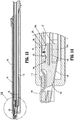
FIG. 1 is a perspective view, with parts separated, of a surgical stapling system including a surgical stapling apparatus and an anvil buttress loading unit in accordance with the principles of this disclosure; -
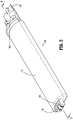
FIG. 2 is an enlarged, perspective view of the anvil buttress loading unit ofFIG.1 ; -
FIG. 3 is a perspective view, with parts separated, of the anvil buttress loading unit shown inFIGS. 1 and2 ; -
FIGS. 4 and 5 are enlarged, perspective views of a distal clip of the anvil buttress loading unit shown inFIGS. 1-3 ; -
FIG. 6 is an enlarged, perspective view of a release strap and a buttress of the anvil buttress loading unit shown inFIGS. 1-3 ; -
FIG. 7 is a side, cross-sectional view of the anvil buttress loading unit as taken along section line 7-7 shown inFIG. 2 ; -
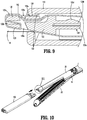
FIGS. 8 and9 are enlarged views of the indicated areas of detail shown inFIG. 7 ; -
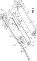
FIG. 10 is a perspective view of the anvil buttress loading unit and an end effector of the surgical stapling apparatus; -
FIG. 11 is an enlarged, perspective view of the indicated area of detail shown inFIG. 10 ; -
FIG. 12 is a perspective view illustrating the anvil buttress loading unit positioned on an anvil assembly of the end effector; -
FIG. 13 is a side, cross-sectional view of the anvil buttress loading unit on the anvil assembly as taken along section line 13-13 shown inFIG. 12 ; -
FIG. 14 is an enlarged view of the indicated area of detail shown inFIG. 13 ; -
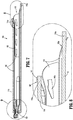
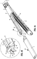
FIG. 15 is a perspective view illustrating a loader of the anvil buttress loading unit separated from the anvil assembly of the end effector with the release strap and the buttress supported on the anvil assembly; and -
FIG. 16 is an enlarged view of the indicated area of detail shown inFIG. 15 . - Embodiments of this disclosure will now be described in detail with reference to the drawing figures wherein like reference numerals identify similar or identical elements. Throughout this description, the term "proximal" refers to a portion of a structure, or component thereof, that is closer to a user, and the term "distal" refers to a portion of the structure, or component thereof, that is farther from the user. Directional reference terms, such as "top," "bottom," "side," and the like, are used to ease description of the embodiments and are not intended to have any limiting effect on the ultimate orientation of a structure or any part thereof. In the following description, well-known functions or constructions are not described in detail to avoid obscuring this disclosure in unnecessary detail.
- Referring now to
FIG. 1 , asurgical stapling system 5, in accordance with this disclosure, includes a surgical stapling apparatus orsurgical stapler 10 and an anvil buttressloading unit 100 for use in stapling tissue and applying one or more buttress materials or surgical buttresses to the tissue. Thesurgical stapling apparatus 10 generally includes ahandle assembly 12 and an elongatedtubular body portion 14 that extends distally from thehandle assembly 12. The elongatedtubular body portion 14 may include asurgical loading unit 16 that is selectively attachable to the elongatedtubular body portion 14. An end effector orjaw assembly 18 extends distally from the elongated tubular body portion 14 (e.g., a distal end portion of the surgical loading unit 16). Thejaw assembly 18 includes ananvil assembly 20 and astaple cartridge assembly 22. Thejaw assembly 18 may be permanently affixed to the elongatedtubular body portion 14 or may be detachable with respect to the elongatedtubular body portion 14 and thus, replaceable with anew jaw assembly 18. Theanvil assembly 20 and/or thestaple cartridge assembly 22 is pivotable with respect to the elongatedtubular body portion 14 such that the anvil and/orstaple cartridge assemblies staple cartridge assemblies staple cartridge assemblies - The
handle assembly 12 of thesurgical stapling apparatus 10 includes astationary handle member 12a, amovable handle member 12b, and abarrel portion 12c. Anarticulation lever 12d is mounted on a forward end of thebarrel portion 12c to facilitate articulation of thejaw assembly 18. Arotatable member 12e is also mounted on the forward end of thebarrel portion 12c, adjacent thearticulation lever 12d. Rotation of therotatable member 12e relative to thebarrel portion 12c rotates the elongatedtubular body portion 14 and thejaw assembly 18 relative to thehandle assembly 12 so as to properly orient the anvil andstaple cartridge assemblies knob 12f is movably positionable along thebarrel portion 12c. Theknob 12f is advanced distally to approximate or close the anvil andstaple cartridge assemblies staple cartridge assemblies movable handle member 12b applies lines of staples (not shown) to tissue captured between the anvil andstaple cartridge assemblies - For a detailed description of the structure and function of exemplary surgical stapling apparatus, reference may be made to
U.S. Patent Nos. 8,256,656 ,7,819,896 , and7,128,253 as well asU.S. Patent Application Serial No. 16/387,882, filed April 18, 2019 U.S. Patent Nos., 7,334,717 ,5,964,394 , and5,915,616 , the entire contents of each of which is incorporated herein by reference. Accordingly, it should be understood that a variety of surgical stapling apparatus may be utilized with the surgical buttresses and/or surgical buttress applicators or loaders of this disclosure such as, for example, laparoscopic staplers, open staplers, transverse anastomosis staplers, and end-to-end anastomosis staplers having a circular staple cartridge and anvil, as well as staple cartridge assemblies housing surgical fasteners other than staples. - Turning now to
FIGS. 2-9 , buttressloading unit 100, which may be in the form of a linear anvil buttress loading unit, includes aloader 110, aclip 120, abuttress 130, and arelease strap 140. -
Loader 110 of buttressloading unit 100 includes anelongated body 112 having astrap support portion 114 and a buttresssupport portion 116 that extend from a proximal end portion ofelongated body 112.Strap support portion 114 ofelongated body 112 includes astrap lance 114a that extends proximally fromstrap support portion 114 to retainrelease strap 140. Buttresssupport portion 116 includes a buttresslance 116a that extends proximally from buttresssupport portion 116 to retain buttress 130 and which is longitudinally offset fromstrap lance 114a. A pair offingers 118 extends from a distal end portion ofelongated body 112 to supportclip 120 withinelongated body 112.Elongated body 112 further defines apassageway 115 therethrough for supporting buttress 130,release strap 140, and clip 120 withinelongated body 112.Passageway 115 opens distally through anaperture 115a extending between the pair offingers 118 for receiving a portion ofclip 120 therethrough. -
Clip 120 of buttressloading unit 100 is selectively attachable toanvil assembly 20 ofend effector 18.Clip 120 includes aclip body 122 havingwings 124 that extend laterally from the sides ofclip body 122 and atongue 126 that extends distally fromclip body 122.Clip body 122 defines abody aperture 122a through an upper surface 122U ofclip body 122.Clip body 122 includes aguide ramp 122b disposed in registration with thebody aperture 122a.Tongue 126 includes aproximal tongue aperture 126a that extends through upper and lower surfaces 122U, 122L ofclip body 122 and adistal tongue aperture 126b that extends distally through anend face 126f of tongue 126 (seeFIG. 9 ). Distal andproximal tongue apertures body aperture 122a ofclip body 122 to enablerelease strap 140 to be passed (e.g., folded and thread) therethrough as seen inFIG. 9 .Clip body 122 further includes acatch assembly 128 that extends proximally fromclip body 122.Catch assembly 128 includes asupport arm 128a rigidly secured to clipbody 122 and atab 128b that is flexibly coupled to clip body 122 (e.g., cantilevered) and spaced fromsupport arm 128a by agap 128c so thattab 128b can selectively flex from a first or permanent position (as shown inFIG. 5 ), to a second or temporary position intogap 128c (not shown), as indicated by arrow "A."Tab 128b is configured to bias toward the first position.Tab 128b supports acatch 128d, which, although shown as having a rounded configuration, can have any suitable shape or configuration (e.g., cylindrical, hook, triangular, etc.). - Buttress 130 of buttress
loading unit 100 is also selectively attachable toanvil assembly 20 ofend effector 18.Buttress 130 includes a buttressbody 132 havingside arms 134 extending laterally from opposite sides of buttressbody 132.Side arms 134 define a plurality ofside slots 134a. Theside slots 134a are longitudinally spaced apart from one another alongside arms 134. Buttressbody 132 defines alance slot 132a through a proximal end portion of buttressbody 132 for receiving buttresslance 116a ofloader 110 therein. Buttressbody 132 further includes adistal arch 136 supported on a distal end portion of buttressbody 132.Distal arch 136 defines adistal opening 136a that extends through the distal end portion of buttressbody 132. - The surgical buttresses of this disclosure may be fabricated from biocompatible materials which are bioabsorbable or non-absorbable, natural or synthetic materials. It should be understood that any combination of natural, synthetic, bioabsorbable, and/or non-bioabsorbable materials may be used to form the surgical buttresses. The surgical buttresses may be biodegradable (e.g., formed from bioabsorbable and bioresorable materials) such that the surgical buttresses decompose or are broken down (physically or chemically) under physiological conditions in the body, and the degradation products are excretable or absorbable by the body. Components or portions of the surgical buttresses may be formed from the same material or different materials.
- In embodiments, at least a portion of the surgical buttresses are made from biodegradable materials selected from the following group: natural collagenous materials, cat gut, and synthetic resins including those derived from alkylene carbonates, trimethylene carbonate, tetramethylene carbonate, caprolactone, valerolactone, dioxanone, polyanhydrides, polyesters, polyacrylates, polymethylmethacrylates, polyurethanes, glycolic acid, lactic acid, glycolide, lactide, polyhydroxy butyrates, polyorthoester, polyhydroxy alkanoates, homopolymers thereof, and copolymers thereof. In embodiments, at least a portion of the surgical buttresses may be made from non-biodegradable materials selected from the following group: polyolefins, polyethylene, polydimethylsiloxane, polypropylene, copolymers of polyethylene and polypropylene, blends of polyethylene and polypropylene, ultra high molecular weight polyethylene, polyamides, polyesters, polyethylene terephthalate, polytetrafluoroethylene, polyether-esters, polybutester, polytetramethylene ether glycol, 1,4-butanediol, and polyurethanes.
- The surgical buttresses may be porous, non-porous, or combinations thereof. Suitable porous structures include, for example, fibrous structures (e.g., knitted structures, woven structures, and non-woven structures) and/or foams (e.g., open or closed cell foams). Suitable non-porous structures include, for example, films. The surgical buttresses, or portions thereof, may be a non-woven structure formed by melt-blown or melt-spun methods, a mesh material, a braid material, and/or a molded or extruded sheet. The surgical buttresses, or portions thereof, may be a single porous or non-porous layer, or include a plurality of layers including any combination of porous and/or non-porous layers.
- The surgical buttresses may be provided and/or sold as part of the buttress loading unit. Alternatively, the surgical buttress(es) and the buttress loading unit may be provided and/or sold separately and assembled by the user. In embodiments, one or more surgical buttresses and one or more buttress loading units are provided in a kit. In some embodiments, the kit further includes one or more end effectors (and/or surgical loading units) and, in certain embodiments, the kit further includes a surgical stapler.
- In any of the embodiments disclosed herein, the surgical buttresses can include, or be used with, brachytherapy, chemotherapy, other medical materials or pharmaceuticals. The buttress portion of the surgical buttress can have pockets, apertures, or other features for retaining brachytherapy seeds with the buttress portion, or brachytherapy seeds or materials can be incorporated into a suture or sutures that are threaded into or through the buttress portion or otherwise attached thereto. A coating having brachytherapy materials can be applied to a buttress portion of a surgical buttress by spraying or dipping. Chemotherapy pharmaceuticals or agents can be incorporated into the buttress portion of the surgical buttress, coated thereon, or otherwise applied as part of a suture or other feature secured to the buttress portion.
-
Release strap 140 of buttressloading unit 100 includes anelongated portion 142 that extends proximally to adetent assembly 144 configured to releasably secure buttress 130 to theanvil assembly 20 ofend effector 18.Detent assembly 144 includes adetent body portion 146 having a plurality ofdetents 146a supported on opposed sides of thedetent body portion 146 that are selectively receivable byside slots 134a of buttress 130 to securerelease strap 140 and buttress 130 together (seeFIG. 6 ).Detent body portion 146 defines alance slot 148 in a proximal end portion thereof for receivingstrap lance 114a ofloader 110 therein. - With reference to
FIGS. 10-16 ,anvil assembly 20 ofend effector 18 defines asupport slot 20a and acatch aperture 20b in a distal end portion thereof for receivingcatch assembly 128 ofclip 120.Support slot 20a ofanvil assembly 20 receivescatch assembly 128 therein asanvil loading unit 100 is advanced overanvil assembly 20 in a proximal direction relative toanvil assembly 20, as indicated by arrow "P" (FIG. 12 ), so thattab 128b ofclip 120 flexes downwardly intogap 128c (e.g., the second position oftab 128b) towardsupport arm 128a ofclip 120 in response to aninner surface 20c ofanvil assembly 20 engagingcatch 128d. Continued proximal advancement ofclip 120 causes catch 128d ofclip 120 to cam alonginner surface 20c ofanvil assembly 20 untilcatch 128d extends intocatch aperture 20b so thattab 128b can flex back to the first position oftab 128b, as indicated by arrow "B," andcatch 128d securesclip 120 toanvil assembly 20 by virtue ofcatch aperture 20b. - With
clip 120 of buttressloading unit 100 secured toanvil assembly 20, andrelease strap 140 and buttress 130 secured to clip 120 andanvil assembly 20,loader 110 of anvil buttressloading unit 100 can be moved in a distal direction relative toanvil assembly 20,clip 120,release strap 140, and buttress 130, as indicated by arrow "D" shown inFIG. 15 . Continued distal movement ofloader 110 relative toanvil assembly 20 causesloader 110 to separate fromanvil assembly 20,clip 120,release strap 140, and buttress 130 so thatend effector 18 withrelease strap 140 and buttress 130 can be utilized to secure buttress 130 to tissue by fasteners (not shown) supported incartridge assembly 22. Once fastening is complete,anvil assembly 20 can be removed withrelease strap 140 attached so thatanvil assembly 20 can be pulled away from buttress 130 while buttress 130 remains attached to the tissue. After pulling out the remaining portions ofrelease strap 140, the process can be repeated as desired. For a more detailed description of exemplary tissue fastening with similar surgical stapling apparatus having release straps and buttresses, reference can be made toU.S. Patent Application Serial No. 16/387,882, filed April 18, 2019 - While several embodiments of the disclosure have been shown in the drawings, it is not intended that the disclosure be limited thereto, as it is intended that the disclosure be as broad in scope as the art will allow and that the specification be read likewise. It is to be understood, therefore, that this disclosure is not limited to the precise embodiments described, and that various other changes and modifications may be effected by one skilled in the art without departing from the scope or spirit of the disclosure. Additionally, the elements and features shown and described in connection with certain embodiments may be combined with the elements and features of certain other embodiments without departing from the scope of this disclosure, and that such modifications and variation are also included within the scope of this disclosure. Therefore, the above description should not be construed as limiting, but merely as exemplifications of preferred embodiments. Thus the scope of the embodiments should be determined by the appended claims and their legal equivalents, rather than by the examples given.
- The invention may be described by reference to the following numbered paragraphs: -
- 1. A surgical stapling system comprising: a surgical stapling apparatus including a first jaw member and a second jaw member configured to fasten tissue grasped between the first and second jaw members; and a buttress loading unit including a loader and a clip supported in the loader, the loader and the clip supporting a release strap and a buttress, the clip configured to selectively attach the release strap and the buttress to the first jaw member when the loader is positioned on the first jaw member.
- 2. The surgical stapling system of
paragraph 1, wherein the clip includes a catch assembly that secures the clip to the first jaw member. - 3. The surgical stapling system of
paragraph 2, wherein the catch assembly includes a support arm and a tab that is movably positioned relative to the support arm. - 4. The surgical stapling system of paragraph 3, wherein the first jaw member defines a support slot positioned to receive the support arm and the tab of the catch assembly.
- 5. The surgical stapling system of
paragraph 4, wherein the tab includes a catch that is selectively engagable with a catch aperture defined the first jaw member. - 6. The surgical stapling system of
paragraph 5, wherein the catch aperture is disposed in registration with the support slot. - 7. The surgical stapling system of paragraph 6, wherein the first jaw member is an anvil assembly.
- 8. The surgical stapling system of
paragraph 1, wherein the release strap includes an elongated portion that extends from a detent assembly, the elongated portion positioned to couple to the clip, the detent assembly positioned to couple to the loader. - 9. The surgical stapling system of
paragraph 8, wherein the buttress includes a first end portion that couples to the loader and a second end portion that couples to the clip. - 10. The surgical stapling system of
paragraph 8, wherein the detent assembly of the release strap is configured to couple to the buttress to secure the release strap to the buttress. - 11. A buttress loading unit comprising: a buttress; a release strap; and a loader configured to support the buttress and the release strap for selective attachment of the buttress and the release strap to a jaw member of a surgical stapling apparatus, the loader having a first end portion including a first lance that releasably couples to the buttress and a second lance that releasably couples to the release strap, the loader having a second end portion supporting a clip, the clip positioned to releasably secure the release strap and the buttress to the second end portion of the loader.
- 12. The buttress loading unit of
paragraph 11, wherein the buttress defines a lance slot in a proximal end portion thereof for receiving the first lance of the loader. - 13. The buttress loading unit of
paragraph 12, wherein the buttress includes an arch on a distal end portion thereof, the arch defining a distal opening that is positioned to receive a tongue of the clip to secure the buttress to the clip. - 14. The buttress loading unit of
paragraph 13, wherein the clip defines a plurality of apertures therethrough, the plurality of apertures positioned to receive an elongated portion of the release strap. - 15. The buttress loading unit of
paragraph 14, wherein the elongated portion of the release strap is positionable through the distal opening of the buttress. - 16. The buttress loading unit of
paragraph 11, wherein the first and second lances are longitudinally offset from one another. - 17. The buttress loading unit of 11, wherein the release strap includes a detent assembly having a plurality of detents and the buttress includes a plurality of side slots positioned to receive the plurality of detents to couple the release strap to the buttress.
- 18. A surgical buttress loader for securing a release strap and a buttress to an end effector of a surgical stapling apparatus, the surgical buttress loader comprising: an elongated body having a strap support portion and a buttress support portion that extend from a proximal end portion of the elongated body, the strap support portion including a strap lance that extends proximally from the strap support portion, the buttress support portion including a buttress lance that extends proximally from the buttress support portion, the strap lance configured to releasably secure the release strap to the strap support portion, the buttress lance configured to releasably secure the buttress to the buttress support portion.
- 19. The surgical buttress loader of
paragraph 18, wherein the elongated body defines a passageway between the strap support portion and the buttress support portion for receiving the buttress and the release strap therethrough. - 20. The surgical buttress loader of paragraph 19, wherein the passageway opens distally through an aperture defined by the elongated body, the aperture configured to receive a clip that secures the buttress and the release strap to the elongated body.
Claims (15)
- A surgical stapling system comprising:a surgical stapling apparatus including a first jaw member and a second jaw member configured to fasten tissue grasped between the first and second jaw members; anda buttress loading unit including a loader and a clip supported in the loader, the loader and the clip supporting a release strap and a buttress, the clip configured to selectively attach the release strap and the buttress to the first jaw member when the loader is positioned on the first jaw member.
- The surgical stapling system of claim 1, wherein the clip includes a catch assembly that secures the clip to the first jaw member.
- The surgical stapling system of claim 2, wherein the catch assembly includes a support arm and a tab that is movably positioned relative to the support arm.
- The surgical stapling system of claim 3, wherein the first jaw member defines a support slot positioned to receive the support arm and the tab of the catch assembly.
- The surgical stapling system of claim 4, wherein the tab includes a catch that is selectively engagable with a catch aperture defined the first jaw member.
- The surgical stapling system of claim 5, wherein the catch aperture is disposed in registration with the support slot.
- The surgical stapling system of claim 6, wherein the first jaw member is an anvil assembly.
- The surgical stapling system of any preceding claim, wherein the release strap includes an elongated portion that extends from a detent assembly, the elongated portion positioned to couple to the clip, the detent assembly positioned to couple to the loader; preferably wherein the buttress includes a first end portion that couples to the loader and a second end portion that couples to the clip; and/or wherein the detent assembly of the release strap is configured to couple to the buttress to secure the release strap to the buttress.
- A buttress loading unit comprising:a buttress;a release strap; anda loader configured to support the buttress and the release strap for selective attachment of the buttress and the release strap to a jaw member of a surgical stapling apparatus, the loader having a first end portion including a first lance that releasably couples to the buttress and a second lance that releasably couples to the release strap, the loader having a second end portion supporting a clip, the clip positioned to releasably secure the release strap and the buttress to the second end portion of the loader.
- The buttress loading unit of claim 9, wherein the buttress defines a lance slot in a proximal end portion thereof for receiving the first lance of the loader; preferably wherein the buttress includes an arch on a distal end portion thereof, the arch defining a distal opening that is positioned to receive a tongue of the clip to secure the buttress to the clip.
- The buttress loading unit of claim 9 or claim 10, wherein the clip defines a plurality of apertures therethrough, the plurality of apertures positioned to receive an elongated portion of the release strap; preferably wherein the elongated portion of the release strap is positionable through the distal opening of the buttress.
- The buttress loading unit of any of claims 9 to 11, wherein the first and second lances are longitudinally offset from one another.
- The buttress loading unit of any of claims 9 to 12, wherein the release strap includes a detent assembly having a plurality of detents and the buttress includes a plurality of side slots positioned to receive the plurality of detents to couple the release strap to the buttress.
- A surgical buttress loader for securing a release strap and a buttress to an end effector of a surgical stapling apparatus, the surgical buttress loader comprising:
an elongated body having a strap support portion and a buttress support portion that extend from a proximal end portion of the elongated body, the strap support portion including a strap lance that extends proximally from the strap support portion, the buttress support portion including a buttress lance that extends proximally from the buttress support portion, the strap lance configured to releasably secure the release strap to the strap support portion, the buttress lance configured to releasably secure the buttress to the buttress support portion. - The surgical buttress loader of claim 14, wherein the elongated body defines a passageway between the strap support portion and the buttress support portion for receiving the buttress and the release strap therethrough; preferably wherein the passageway opens distally through an aperture defined by the elongated body, the aperture configured to receive a clip that secures the buttress and the release strap to the elongated body.
Applications Claiming Priority (1)
| Application Number | Priority Date | Filing Date | Title |
|---|---|---|---|
| US16/565,668 US11969169B2 (en) | 2019-09-10 | Anvil buttress loading unit for a surgical stapling apparatus |
Publications (2)
| Publication Number | Publication Date |
|---|---|
| EP3791801A2 true EP3791801A2 (en) | 2021-03-17 |
| EP3791801A3 EP3791801A3 (en) | 2021-03-31 |
Family
ID=72470179
Family Applications (1)
| Application Number | Title | Priority Date | Filing Date |
|---|---|---|---|
| EP20195303.1A Pending EP3791801A3 (en) | 2019-09-10 | 2020-09-09 | Anvil buttress loading unit for a surgical stapling apparatus |
Country Status (5)
| Country | Link |
|---|---|
| EP (1) | EP3791801A3 (en) |
| JP (1) | JP2021041150A (en) |
| CN (1) | CN112545596A (en) |
| AU (1) | AU2020210136A1 (en) |
| CA (1) | CA3088519A1 (en) |
Citations (6)
| Publication number | Priority date | Publication date | Assignee | Title |
|---|---|---|---|---|
| US5915616A (en) | 1991-10-18 | 1999-06-29 | United States Surgical Corporation | Surgical fastener applying apparatus |
| US5964394A (en) | 1996-03-15 | 1999-10-12 | United States Surgical Corporation | Surgical fastener applying device |
| US7128253B2 (en) | 1995-08-28 | 2006-10-31 | United States Surgical Corporation | Surgical stapler |
| US7334717B2 (en) | 2001-10-05 | 2008-02-26 | Tyco Healthcare Group Lp | Surgical fastener applying apparatus |
| US7819896B2 (en) | 2002-10-04 | 2010-10-26 | Tyco Healthcare Group Lp | Tool assembly for a surgical stapling device |
| US8256656B2 (en) | 1997-09-23 | 2012-09-04 | Tyco Healthcare Group Lp | Surgical stapling apparatus |
Family Cites Families (6)
| Publication number | Priority date | Publication date | Assignee | Title |
|---|---|---|---|---|
| US6656193B2 (en) * | 2001-05-07 | 2003-12-02 | Ethicon Endo-Surgery, Inc. | Device for attachment of buttress material to a surgical fastening device |
| US9332974B2 (en) * | 2010-09-30 | 2016-05-10 | Ethicon Endo-Surgery, Llc | Layered tissue thickness compensator |
| US8967448B2 (en) * | 2011-12-14 | 2015-03-03 | Covidien Lp | Surgical stapling apparatus including buttress attachment via tabs |
| US10548593B2 (en) * | 2015-03-25 | 2020-02-04 | Ethicon Llc | Flowable bioabsorbable polymer adhesive for releasably attaching a staple buttress to a surgical stapler |
| US10166023B2 (en) * | 2015-08-24 | 2019-01-01 | Ethicon Llc | Method of applying a buttress to a surgical stapler end effector |
| US10945733B2 (en) * | 2017-08-23 | 2021-03-16 | Covidien Lp | Surgical buttress reload and tip attachment assemblies for surgical stapling apparatus |
-
2020
- 2020-07-27 AU AU2020210136A patent/AU2020210136A1/en active Pending
- 2020-07-30 CA CA3088519A patent/CA3088519A1/en active Pending
- 2020-08-06 JP JP2020133610A patent/JP2021041150A/en active Pending
- 2020-09-03 CN CN202010914866.9A patent/CN112545596A/en active Pending
- 2020-09-09 EP EP20195303.1A patent/EP3791801A3/en active Pending
Patent Citations (6)
| Publication number | Priority date | Publication date | Assignee | Title |
|---|---|---|---|---|
| US5915616A (en) | 1991-10-18 | 1999-06-29 | United States Surgical Corporation | Surgical fastener applying apparatus |
| US7128253B2 (en) | 1995-08-28 | 2006-10-31 | United States Surgical Corporation | Surgical stapler |
| US5964394A (en) | 1996-03-15 | 1999-10-12 | United States Surgical Corporation | Surgical fastener applying device |
| US8256656B2 (en) | 1997-09-23 | 2012-09-04 | Tyco Healthcare Group Lp | Surgical stapling apparatus |
| US7334717B2 (en) | 2001-10-05 | 2008-02-26 | Tyco Healthcare Group Lp | Surgical fastener applying apparatus |
| US7819896B2 (en) | 2002-10-04 | 2010-10-26 | Tyco Healthcare Group Lp | Tool assembly for a surgical stapling device |
Also Published As
| Publication number | Publication date |
|---|---|
| CN112545596A (en) | 2021-03-26 |
| US20210068827A1 (en) | 2021-03-11 |
| AU2020210136A1 (en) | 2021-03-25 |
| JP2021041150A (en) | 2021-03-18 |
| EP3791801A3 (en) | 2021-03-31 |
| CA3088519A1 (en) | 2021-03-10 |
Similar Documents
| Publication | Publication Date | Title |
|---|---|---|
| EP3834766A2 (en) | Anvil buttress loading for a surgical stapling apparatus | |
| US11596404B2 (en) | Structure for attaching buttress to anvil and/or cartridge of surgical stapling instrument | |
| US20200268386A1 (en) | Staple line reinforcement for anvil and cartridge | |
| US11571208B2 (en) | Surgical buttress loading units | |
| AU2012200850B2 (en) | Surgical instrument buttress attachment | |
| US9610080B2 (en) | Staple line reinforcement for anvil and cartridge | |
| EP2462880B2 (en) | Surgical apparatus including surgical buttress | |
| US20220409207A1 (en) | Surgical buttress assemblies | |
| US11272937B2 (en) | Surgical staple cartridge for supporting surgical buttress material | |
| EP3791801A2 (en) | Anvil buttress loading unit for a surgical stapling apparatus | |
| EP4000536A1 (en) | Stapler line reinforcement continuity | |
| US11969169B2 (en) | Anvil buttress loading unit for a surgical stapling apparatus | |
| AU2015258189B2 (en) | Surgical apparatus including surgical buttress |
Legal Events
| Date | Code | Title | Description |
|---|---|---|---|
| PUAI | Public reference made under article 153(3) epc to a published international application that has entered the european phase |
Free format text: ORIGINAL CODE: 0009012 |
|
| STAA | Information on the status of an ep patent application or granted ep patent |
Free format text: STATUS: THE APPLICATION HAS BEEN PUBLISHED |
|
| PUAL | Search report despatched |
Free format text: ORIGINAL CODE: 0009013 |
|
| AK | Designated contracting states |
Kind code of ref document: A2 Designated state(s): AL AT BE BG CH CY CZ DE DK EE ES FI FR GB GR HR HU IE IS IT LI LT LU LV MC MK MT NL NO PL PT RO RS SE SI SK SM TR |
|
| AX | Request for extension of the european patent |
Extension state: BA ME |
|
| AK | Designated contracting states |
Kind code of ref document: A3 Designated state(s): AL AT BE BG CH CY CZ DE DK EE ES FI FR GB GR HR HU IE IS IT LI LT LU LV MC MK MT NL NO PL PT RO RS SE SI SK SM TR |
|
| AX | Request for extension of the european patent |
Extension state: BA ME |
|
| RIC1 | Information provided on ipc code assigned before grant |
Ipc: A61B 17/072 20060101AFI20210219BHEP |
|
| STAA | Information on the status of an ep patent application or granted ep patent |
Free format text: STATUS: REQUEST FOR EXAMINATION WAS MADE |
|
| 17P | Request for examination filed |
Effective date: 20210930 |
|
| RBV | Designated contracting states (corrected) |
Designated state(s): AL AT BE BG CH CY CZ DE DK EE ES FI FR GB GR HR HU IE IS IT LI LT LU LV MC MK MT NL NO PL PT RO RS SE SI SK SM TR |