EP3791768A1 - A dishwasher with improved washing effectiveness - Google Patents
A dishwasher with improved washing effectiveness Download PDFInfo
- Publication number
- EP3791768A1 EP3791768A1 EP20193634.1A EP20193634A EP3791768A1 EP 3791768 A1 EP3791768 A1 EP 3791768A1 EP 20193634 A EP20193634 A EP 20193634A EP 3791768 A1 EP3791768 A1 EP 3791768A1
- Authority
- EP
- European Patent Office
- Prior art keywords
- shaft
- spray arm
- dishwasher
- water
- plate
- Prior art date
- Legal status (The legal status is an assumption and is not a legal conclusion. Google has not performed a legal analysis and makes no representation as to the accuracy of the status listed.)
- Granted
Links
Images

Classifications
-
- A—HUMAN NECESSITIES
- A47—FURNITURE; DOMESTIC ARTICLES OR APPLIANCES; COFFEE MILLS; SPICE MILLS; SUCTION CLEANERS IN GENERAL
- A47L—DOMESTIC WASHING OR CLEANING; SUCTION CLEANERS IN GENERAL
- A47L15/00—Washing or rinsing machines for crockery or tableware
- A47L15/14—Washing or rinsing machines for crockery or tableware with stationary crockery baskets and spraying devices within the cleaning chamber
- A47L15/16—Washing or rinsing machines for crockery or tableware with stationary crockery baskets and spraying devices within the cleaning chamber with rigidly-mounted spraying devices
-
- A—HUMAN NECESSITIES
- A47—FURNITURE; DOMESTIC ARTICLES OR APPLIANCES; COFFEE MILLS; SPICE MILLS; SUCTION CLEANERS IN GENERAL
- A47L—DOMESTIC WASHING OR CLEANING; SUCTION CLEANERS IN GENERAL
- A47L15/00—Washing or rinsing machines for crockery or tableware
- A47L15/42—Details
- A47L15/4278—Nozzles
- A47L15/4282—Arrangements to change or modify spray pattern or direction
-
- A—HUMAN NECESSITIES
- A47—FURNITURE; DOMESTIC ARTICLES OR APPLIANCES; COFFEE MILLS; SPICE MILLS; SUCTION CLEANERS IN GENERAL
- A47L—DOMESTIC WASHING OR CLEANING; SUCTION CLEANERS IN GENERAL
- A47L15/00—Washing or rinsing machines for crockery or tableware
- A47L15/42—Details
- A47L15/4278—Nozzles
Definitions
- the present invention relates to a dishwasher with improved washing efficiency.
- Dishwashers generally comprise upper and lower racks which are placed inside the washing tub and wherein the kitchenware items such as pots, plates, etc. are placed.
- a spray arm is provided, which is connected to the water line and which rotates around its own axis so as to spray water onto the items in the rack.
- the holes on the upper spray arm connected to the rack and the lower spray arm connected to the lower region of the washing tub the water is delivered into the washing tub.
- the position and the geometry of said holes are designed such that the sprayed water scans more area in the washing tub so as to reach all the surfaces of the dishes.
- the spray arm rotates as a result of the angular momentum generated by the water sprayed through the holes arranged thereon.
- the holes generating said momentum are generally positioned towards the ends of the spray arm.
- the water leaving the holes hits the dirt dishes and plays a critical role in removing the dirt from the surfaces.
- one of the basic principles is the mechanical effect generated by the sprayed water. Increase in the mechanical effect positively affects the washing performance. Low water flow rate and pressure decreases the washing performance.
- additional spray arms in the vicinity of the spray arm are used, which spray extra water to the region in the rack where dishes with relatively more intense dirts are placed, thus enabling said dishes to be effectively washed.
- Said additional spray arms are used to better clean heavy stains, for example loads such as burnt pot, etc.
- a dishwasher having a nozzle which extends from the side of the spray arm and which sprays water to a region of the rack situated thereabove.
- the additional spray arm disclosed in this document moves forward by means of the rotating nozzle provided thereon, and performs the washing process for a certain time depending on the washing algorithm. As the water sprayed from the nozzles on the lower spray arm hits the rib on the additional spray arm, the additional spray arm returns to the initial position.
- the operational frequency of the additional spray arm is controlled by an algorithm. Since the forward movement of the additional spray arm is provided by a rotating nozzle, some of the total fluid energy is used for pushing the additional spray arm forward. This decreases the energy of the water sprayed from the nozzles used for washing. Since the energy of the washing nozzles decreases, the mechanical effect applied for removing dirts also decreases, adversely affecting the washing performance.
- the aim of the present invention is the realization of a dishwasher with improved washing efficiency.
- the dishwasher realized in order to attain the aim of the present invention, explicated in the first claim and the respective claims thereof, comprises an additional spray arm having a body, a lid, at least one spraying member which is pivotably attached so as to rotate around the point of attachment to the body, a shaft which is positioned at the center of the body and which rotates around its own axis with the effect of the water coming from the water line, a first pin which extends perpendicularly to the shaft and a first plate which is contacted by the first pin and which moves the spraying member by linearly moving in the contact direction of the first pin.
- the additional spray arm used for better washing very dirty dishes in addition to the lower and upper spray arms in the dishwasher is enabled to be operated only by moving the spraying members without using any rotating nozzle.
- the spraying members on the additional spray arm are enabled to move to right and left or forwards and backwards.
- the additional spray arm is enabled to move in a direction opposite to the movement direction of the spraying members. Consequently, without using any rotating nozzle, the additional spray arm is moved and the washing performance is improved.
- the body and the lid are circular, and the spraying members are disposed in the body close to the edge of the body at certain intervals in the radial direction.
- the spraying member comprises an inlet which is connected to the water line, an outlet which sprays water, and an intermediate member which is arranged between the inlet and the outlet and which enables the outlet to rotate 360° around approximately the point where the spraying member is fixed.
- the lid is attached onto the body while the body accommodates the spraying members, the shaft and the first plate, and comprises holes which are aligned with the outlets of the spraying members and through which the outlets extend outside the body when the lid is attached onto the body.
- the lid protecting the spraying members, the shaft and the first plate against external factors after the spraying members, the shaft and the first plate are placed into the body is placed onto the body so as to cover the body such that the holes towards which the outlets of the spraying members extend are aligned with the outlets.
- the additional spray arm comprises a shaft which is disposed at the center of the spraying members positioned in the radial direction at the center of the body and perpendicularly to the base of the body so as to rotate around its own axis with the effect of the water coming from the water line.
- the additional spray arm further comprises a first pin which extends on the shaft outwards from the shaft so as to be perpendicular to the axis of the shaft, and a second pin which extends outwards from the shaft in a parallel horizontal direction opposite to the first pin such that a certain distance in the vertical axis remains therebetween.
- the additional spray arm further comprises a first plate and a second plate which are respectively aligned with the first pin and the second pin and which are positioned in the body so as to be at the center of the spraying members such that a certain distance in the vertical axis remains therebetween and that the shaft and the pins are positioned at the center of the first plate and the second plate.
- a housing surrounding the shaft and the first and second pins is arranged at the center of the first and second plates, and a recess is arranged at the point where the first and second plates are seated onto the intermediate member and where the first plate contacts the outlet and the second plate contacts the inlet.
- One or more than one cut-out is provided on the first and second plates.
- the first and second plates are enabled to be light, providing savings in material.
- the shaft By means of the shaft, the first and second pins and the first and second plates which are provided on the additional spray arm, all the spraying members are enabled to face the same direction.
- the shaft, the first and second pins and the first and second plates work as a cam-shaft system, thus enabling the spraying arms in contact with the first and second plates to move.
- the plate By means of the radial movement of the shaft, the plate linearly moves the spraying members which are in contact with the former. Thus, the circular movement is converted into linear movement.
- the dishwasher comprises a washing tub (1); at least one rack which is disposed in the washing tub (1) and wherein the items to be washed are placed; at least one spray arm (2) which is connected to the water line so as to spray water into the rack and the washing tub (1); and one or more than one additional spray arm (3) which is positioned in the vicinity of the spray arm (2) and which enables a region of the washing tub (1) to be swept with water by means of the water coming from the water line ( Figure 1 ).
- the additional spray arm (3) comprises a body (4), a lid (5), at least one spraying member (6) which is pivotably attached so as to rotate around the point of attachment to the body (4), a shaft (10) which is positioned at the center of the body (4) and which rotates around its own axis with the effect of the water coming from the water line, a first pin (11) which extends perpendicularly to the shaft (10) and a first plate (13) which is contacted by the first pin (11) and which moves the spraying member (6) by linearly moving in the contact direction of the first pin (11).
- the additional spray arm (3) used for better washing very dirty dishes in addition to the lower and upper spray arms (2) in the dishwasher is enabled to be operated only by moving the spraying members (6) without using any rotating nozzle.
- the energy of the water sprayed by the spraying members (6) used for washing and hence the washing efficiency is increased.
- the water pumped with the operation of the circulation pump reaches the spray arm (2).
- the water flows towards the two ends of the spray arm (3) and reaches the flow guiding valve at the outlet of the circulation pump. Afterwards, the water is pumped to the lower or upper spray arm (2) depending on the position of the valve. Three outlets are arranged on the flow guiding valve. The first delivers the water pumped by the circulation pump to the lower spray arm (2), the second to the upper spray arm (2) and the third to the additional spray arm (3) which is used for intensively washing a certain region.
- the water reaching the additional spray arm (3) rotates the shaft (10), and the first pin (11) radially moving together with the shaft (10) hits the first plate (13) and moves the first plate (13) and hence one or more than one spray arm (6) in the same direction which is contact with the wall of the first plate (13) while the additional spray arm (3) move in a direction opposite to the spraying members (6).
- the shaft (10), the first pin (11) and the first plate (13) converts the circular movement to linear movement just like a cam-shaft mechanism.
- the body (4) and the lid (5) are circular, and the spraying members (6) are disposed in the body (4) close to the edge of the body (4) at certain intervals in the radial direction.
- the spraying member (6) comprises an inlet (7) which is connected to the water line, an outlet (8) which sprays water, and an intermediate member (9) which is arranged between the inlet (7) and the outlet (8) and which enables the outlet (8) to rotate 360° around approximately the point where the spraying member (6) is fixed.
- the spraying member (6) is fixed to the body (4) by means of a pivot.
- the lid (5) is attached onto the body (4) while the body (4) accommodates the spraying members (6), the shaft (10) and the first plate (13), and comprises holes (18) which are aligned with the outlets (() of the spraying members (6) and through which the outlets (8) extend outside the body (4) when the lid (5) is attached onto the body (4).
- the lid (5) protecting the spraying members (6), the shaft (10) and the first plate (13) against external factors after the spraying members (6), the shaft (10) and the first plate (13) are placed into the body (4) is placed onto the body (4) so as to cover the body (4) such that the holes (18) towards which the outlets (8) of the spraying members (6) extend are aligned with the outlets (8).
- the additional spray arm (3) comprises a shaft (10) which is disposed at the center of the spraying members (6) positioned in the radial direction at the center of the body (4) and perpendicularly to the base of the body (4) so as to rotate around its own axis with the effect of the water coming from the water line.
- the additional spray arm (3) further comprises a first pin (11) which extends on the shaft (10) outwards from the shaft (10) so as to be perpendicular to the axis of the shaft (10), and a second pin (12) which extends outwards from the shaft (10) in a parallel horizontal direction opposite to the first pin (11) such that a certain distance in the vertical axis remains therebetween.
- the additional spray arm (3) further comprises a first plate (13) and a second plate (14) which are respectively aligned with the first and second pins (11 and 12) and which are positioned in the body (4) so as to be at the center of the spraying members (6) such that a certain distance in the vertical axis remains therebetween and that the shaft (10) and the first second pins (11 and 12) are positioned at the center of the first plate (13) and the second plate (14) ( Figure 4 ).
- a housing (15) surrounding the shaft (10) and the first and second pins (11 and 12) is arranged at the center of the first and second plates (13 and 14), and a recess (16) is arranged at the point where the first and second plates (13 and 14) are seated onto the intermediate member (9) and where the first plate (13) contacts the outlet (8) and the second plate (14) contacts the inlet (7).
- the water reaching the additional spray arm (3) rotates the shaft (10), and the first pin (11) radially moving together with the shaft (10) hits the housing (15) on the first plate (13) and the second pin (12) hits the housing (15) on the second plate (14) so as to move the first plate (13) and the second plate (14), hence one or more than one spray arm (6) which is contact with the recesses (16) at the wall of the first plate (13) and the second plate (14) while the additional spray arm (3) move in a direction opposite to the spraying members (6).
- the first plate (13) contacts the outlets (8) on the spraying members (6) and the second plate (14) contacts the inlets (7) on the second plate (14), thus enabling the spraying members (6) to face the same direction.
- One or more than one cut-out (17) is provided on the first and second plates (13 and 14).
- the first and second plates (13 and 14) are enabled to be light, providing savings in material.
- the first and second plates (13 and 14) are elliptical.
- the spraying arms (6) face different directions.
- the additional spray arm (3) is enabled to rotate clockwise or counterclockwise, thus enabling the sprayed water to act on the dishes in the washing tub (1) for a longer period of time.
- the housing (15) is quadrilateral.
- the first and second pins (11 and 12) contact the long side of the housing (15) arranged on the first and second plates (13 and 14).
Landscapes
- Washing And Drying Of Tableware (AREA)
Abstract
Description
- The present invention relates to a dishwasher with improved washing efficiency.
- Dishwashers generally comprise upper and lower racks which are placed inside the washing tub and wherein the kitchenware items such as pots, plates, etc. are placed. Under each rack, a spray arm is provided, which is connected to the water line and which rotates around its own axis so as to spray water onto the items in the rack. By means of the holes on the upper spray arm connected to the rack and the lower spray arm connected to the lower region of the washing tub, the water is delivered into the washing tub. The position and the geometry of said holes are designed such that the sprayed water scans more area in the washing tub so as to reach all the surfaces of the dishes. In the dishwasher, the spray arm rotates as a result of the angular momentum generated by the water sprayed through the holes arranged thereon. The holes generating said momentum are generally positioned towards the ends of the spray arm. The water leaving the holes hits the dirt dishes and plays a critical role in removing the dirt from the surfaces. In the washing process of the dishwasher, one of the basic principles is the mechanical effect generated by the sprayed water. Increase in the mechanical effect positively affects the washing performance. Low water flow rate and pressure decreases the washing performance.
- In the state of the art dishwashers, additional spray arms in the vicinity of the spray arm are used, which spray extra water to the region in the rack where dishes with relatively more intense dirts are placed, thus enabling said dishes to be effectively washed. Said additional spray arms are used to better clean heavy stains, for example loads such as burnt pot, etc.
- In such state of the art embodiments, it is observed that additional spray arms cannot sweep the relevant region efficiently and cannot spray water effectively. Moreover, the complex structure of the additional spray arms increases the production costs.
- In the state of the art European Patent Application Document No.
EP1549196 , a dishwasher is disclosed, having a nozzle which extends from the side of the spray arm and which sprays water to a region of the rack situated thereabove. - Another document in the state of the art is the International Patent Application No.
WO200401974 - Another state of the art embodiment is disclosed in the European Patent Application No.
EP3030131 . The additional spray arm disclosed in this document moves forward by means of the rotating nozzle provided thereon, and performs the washing process for a certain time depending on the washing algorithm. As the water sprayed from the nozzles on the lower spray arm hits the rib on the additional spray arm, the additional spray arm returns to the initial position. The operational frequency of the additional spray arm is controlled by an algorithm. Since the forward movement of the additional spray arm is provided by a rotating nozzle, some of the total fluid energy is used for pushing the additional spray arm forward. This decreases the energy of the water sprayed from the nozzles used for washing. Since the energy of the washing nozzles decreases, the mechanical effect applied for removing dirts also decreases, adversely affecting the washing performance. - The aim of the present invention is the realization of a dishwasher with improved washing efficiency.
- The dishwasher realized in order to attain the aim of the present invention, explicated in the first claim and the respective claims thereof, comprises an additional spray arm having a body, a lid, at least one spraying member which is pivotably attached so as to rotate around the point of attachment to the body, a shaft which is positioned at the center of the body and which rotates around its own axis with the effect of the water coming from the water line, a first pin which extends perpendicularly to the shaft and a first plate which is contacted by the first pin and which moves the spraying member by linearly moving in the contact direction of the first pin.
- By means of the present invention, the additional spray arm used for better washing very dirty dishes in addition to the lower and upper spray arms in the dishwasher is enabled to be operated only by moving the spraying members without using any rotating nozzle. Thus, since no rotating nozzle is used, the energy of the water sprayed by the spraying members used for washing and hence the washing efficiency is increased. Moreover, as if by using a cam mechanism, the spraying members on the additional spray arm are enabled to move to right and left or forwards and backwards. Thus, the additional spray arm is enabled to move in a direction opposite to the movement direction of the spraying members. Consequently, without using any rotating nozzle, the additional spray arm is moved and the washing performance is improved.
- In the embodiment of the present invention, the body and the lid are circular, and the spraying members are disposed in the body close to the edge of the body at certain intervals in the radial direction.
- In the embodiment of the present invention, the spraying member comprises an inlet which is connected to the water line, an outlet which sprays water, and an intermediate member which is arranged between the inlet and the outlet and which enables the outlet to rotate 360° around approximately the point where the spraying member is fixed.
- In the embodiment of the present invention, the lid is attached onto the body while the body accommodates the spraying members, the shaft and the first plate, and comprises holes which are aligned with the outlets of the spraying members and through which the outlets extend outside the body when the lid is attached onto the body. In the embodiment of the present invention, the lid protecting the spraying members, the shaft and the first plate against external factors after the spraying members, the shaft and the first plate are placed into the body is placed onto the body so as to cover the body such that the holes towards which the outlets of the spraying members extend are aligned with the outlets.
- In the embodiment of the present invention, the additional spray arm comprises a shaft which is disposed at the center of the spraying members positioned in the radial direction at the center of the body and perpendicularly to the base of the body so as to rotate around its own axis with the effect of the water coming from the water line. The additional spray arm further comprises a first pin which extends on the shaft outwards from the shaft so as to be perpendicular to the axis of the shaft, and a second pin which extends outwards from the shaft in a parallel horizontal direction opposite to the first pin such that a certain distance in the vertical axis remains therebetween.
- In the embodiment of the present invention, the additional spray arm further comprises a first plate and a second plate which are respectively aligned with the first pin and the second pin and which are positioned in the body so as to be at the center of the spraying members such that a certain distance in the vertical axis remains therebetween and that the shaft and the pins are positioned at the center of the first plate and the second plate. In this embodiment, a housing surrounding the shaft and the first and second pins is arranged at the center of the first and second plates, and a recess is arranged at the point where the first and second plates are seated onto the intermediate member and where the first plate contacts the outlet and the second plate contacts the inlet.
- One or more than one cut-out is provided on the first and second plates. Thus, the first and second plates are enabled to be light, providing savings in material.
- By means of the shaft, the first and second pins and the first and second plates which are provided on the additional spray arm, all the spraying members are enabled to face the same direction. The shaft, the first and second pins and the first and second plates work as a cam-shaft system, thus enabling the spraying arms in contact with the first and second plates to move. By means of the radial movement of the shaft, the plate linearly moves the spraying members which are in contact with the former. Thus, the circular movement is converted into linear movement.
- By means of the present invention, since no rotating nozzle is used for moving the additional spray arm, the total fluid energy of the system is used only for washing purposes, thus improving the washing performance. By moving the additional spray arm, different areas can be swept. By moving the spraying arms in the same direction, a homogeneous washing process is performed, thus facilitating the removal of dirts from surfaces. Moreover, since no electromechanical component is used, cost advantage is provided.
- The dishwasher realized in order to attain the aim of the present invention is illustrated in the attached figures, where,
-
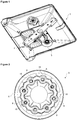
Figure 1 - is the perspective view of a washing arm, a spray arm and an additional spray arm. -
Figure 2 - is the top view of the additional spray arm. -
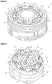
Figure 3 - is the perspective view of the additional spray arm. -
Figure 4 - is the view of the spraying arms in the initial position. -
Figure 5 - is the view of the spraying arms in a position. -
Figure 6 - is the view of the spraying arms in another position. - The elements illustrated in the figures are numbered as follows:
- 1.
- Washing tub
- 2.
- Spray arm
- 3.
- Additional spray arm
- 4.
- Body
- 5.
- Lid
- 6.
- Spraying member
- 7.
- Inlet
- 8.
- Outlet
- 9.
- Intermediate member
- 10.
- Shaft
- 11.
- First pin
- 12.
- Second pin
- 13.
- First plate
- 14.
- Second plate
- 15.
- Housing
- 16.
- Recess
- 17.
- Cut-out
- 18.
- Hole
- The dishwasher comprises a washing tub (1); at least one rack which is disposed in the washing tub (1) and wherein the items to be washed are placed; at least one spray arm (2) which is connected to the water line so as to spray water into the rack and the washing tub (1); and one or more than one additional spray arm (3) which is positioned in the vicinity of the spray arm (2) and which enables a region of the washing tub (1) to be swept with water by means of the water coming from the water line (
Figure 1 ). In the embodiment of the present invention, the additional spray arm (3) comprises a body (4), a lid (5), at least one spraying member (6) which is pivotably attached so as to rotate around the point of attachment to the body (4), a shaft (10) which is positioned at the center of the body (4) and which rotates around its own axis with the effect of the water coming from the water line, a first pin (11) which extends perpendicularly to the shaft (10) and a first plate (13) which is contacted by the first pin (11) and which moves the spraying member (6) by linearly moving in the contact direction of the first pin (11). - By means of the present invention, the additional spray arm (3) used for better washing very dirty dishes in addition to the lower and upper spray arms (2) in the dishwasher is enabled to be operated only by moving the spraying members (6) without using any rotating nozzle. Thus, since no rotating nozzle is used, the energy of the water sprayed by the spraying members (6) used for washing and hence the washing efficiency is increased.
- In the embodiment of the present invention, the water pumped with the operation of the circulation pump reaches the spray arm (2). The water flows towards the two ends of the spray arm (3) and reaches the flow guiding valve at the outlet of the circulation pump. Afterwards, the water is pumped to the lower or upper spray arm (2) depending on the position of the valve. Three outlets are arranged on the flow guiding valve. The first delivers the water pumped by the circulation pump to the lower spray arm (2), the second to the upper spray arm (2) and the third to the additional spray arm (3) which is used for intensively washing a certain region. The water reaching the additional spray arm (3) rotates the shaft (10), and the first pin (11) radially moving together with the shaft (10) hits the first plate (13) and moves the first plate (13) and hence one or more than one spray arm (6) in the same direction which is contact with the wall of the first plate (13) while the additional spray arm (3) move in a direction opposite to the spraying members (6). In this embodiment, the shaft (10), the first pin (11) and the first plate (13) converts the circular movement to linear movement just like a cam-shaft mechanism.
- In the embodiment of the present invention, the body (4) and the lid (5) are circular, and the spraying members (6) are disposed in the body (4) close to the edge of the body (4) at certain intervals in the radial direction.
- In the embodiment of the present invention, the spraying member (6) comprises an inlet (7) which is connected to the water line, an outlet (8) which sprays water, and an intermediate member (9) which is arranged between the inlet (7) and the outlet (8) and which enables the outlet (8) to rotate 360° around approximately the point where the spraying member (6) is fixed. In this embodiment of the present invention, the spraying member (6) is fixed to the body (4) by means of a pivot.
- In the embodiment of the present invention, the lid (5) is attached onto the body (4) while the body (4) accommodates the spraying members (6), the shaft (10) and the first plate (13), and comprises holes (18) which are aligned with the outlets (() of the spraying members (6) and through which the outlets (8) extend outside the body (4) when the lid (5) is attached onto the body (4). In the embodiment of the present invention, the lid (5) protecting the spraying members (6), the shaft (10) and the first plate (13) against external factors after the spraying members (6), the shaft (10) and the first plate (13) are placed into the body (4) is placed onto the body (4) so as to cover the body (4) such that the holes (18) towards which the outlets (8) of the spraying members (6) extend are aligned with the outlets (8).
- In the embodiment of the present invention, the additional spray arm (3) comprises a shaft (10) which is disposed at the center of the spraying members (6) positioned in the radial direction at the center of the body (4) and perpendicularly to the base of the body (4) so as to rotate around its own axis with the effect of the water coming from the water line. The additional spray arm (3) further comprises a first pin (11) which extends on the shaft (10) outwards from the shaft (10) so as to be perpendicular to the axis of the shaft (10), and a second pin (12) which extends outwards from the shaft (10) in a parallel horizontal direction opposite to the first pin (11) such that a certain distance in the vertical axis remains therebetween.
- In the embodiment of the present invention, the additional spray arm (3) further comprises a first plate (13) and a second plate (14) which are respectively aligned with the first and second pins (11 and 12) and which are positioned in the body (4) so as to be at the center of the spraying members (6) such that a certain distance in the vertical axis remains therebetween and that the shaft (10) and the first second pins (11 and 12) are positioned at the center of the first plate (13) and the second plate (14) (
Figure 4 ). In this embodiment, a housing (15) surrounding the shaft (10) and the first and second pins (11 and 12) is arranged at the center of the first and second plates (13 and 14), and a recess (16) is arranged at the point where the first and second plates (13 and 14) are seated onto the intermediate member (9) and where the first plate (13) contacts the outlet (8) and the second plate (14) contacts the inlet (7). In this embodiment of the present invention, the water reaching the additional spray arm (3) rotates the shaft (10), and the first pin (11) radially moving together with the shaft (10) hits the housing (15) on the first plate (13) and the second pin (12) hits the housing (15) on the second plate (14) so as to move the first plate (13) and the second plate (14), hence one or more than one spray arm (6) which is contact with the recesses (16) at the wall of the first plate (13) and the second plate (14) while the additional spray arm (3) move in a direction opposite to the spraying members (6). In this embodiment, the first plate (13) contacts the outlets (8) on the spraying members (6) and the second plate (14) contacts the inlets (7) on the second plate (14), thus enabling the spraying members (6) to face the same direction. - By means of the shaft (10), the first and second pins (11 and 12) and the first and second plates (13 and 14) which are provided on the additional spray arm (3), all the spraying members (6) are enabled to face the same direction. The shaft (10), the first and second pins (11 and 12) and the first and second plates (13 and 14) work as a cam-shaft system, thus enabling the spraying arms (6) in contact with the first and second plates (13 and 14) to move. By means of the radial movement of the shaft (10), the first and second plates (13 and 14) linearly move the spraying members (6) which are in contact with the same. Thus, the circular movement is converted into linear movement (
Figure 5 and Figure 6 ). - One or more than one cut-out (17) is provided on the first and second plates (13 and 14). Thus, the first and second plates (13 and 14) are enabled to be light, providing savings in material.
- In another embodiment of the present invention, the first and second plates (13 and 14) are elliptical.
- In another embodiment of the present invention, the spraying arms (6) face different directions. In this embodiment, the additional spray arm (3) is enabled to rotate clockwise or counterclockwise, thus enabling the sprayed water to act on the dishes in the washing tub (1) for a longer period of time.
- In an embodiment of the present invention, the housing (15) is quadrilateral. In this embodiment of the present invention, the first and second pins (11 and 12) contact the long side of the housing (15) arranged on the first and second plates (13 and 14).
- By means of the present invention, since no rotating nozzle is used for moving the additional spray arm (3), the total fluid energy of the system is used only for washing purposes, thus improving the washing performance. By moving the additional spray arm (3), different areas can be swept. By moving the spraying arms (6) in the same direction, a homogeneous washing process is performed, thus facilitating the removal of dirts from surfaces. Moreover, since no electromechanical component is used, cost advantage is provided.
Claims (11)
- A dishwasher comprising a washing tub (1); at least one rack which is disposed in the washing tub (1) and wherein the items to be washed are placed; and at least one spray arm (2) which is connected to the water line so as to spray water into the rack and the washing tub (1); characterized by one or more than one additional spray arm (3) which is positioned in the vicinity of the spray arm (2) and which enables a region of the washing tub (1) to be swept with water by means of the water coming from the water line, the additional spray arm (3) having a body (4), a lid (5), at least one spraying member (6) which is pivotably attached so as to rotate around the point of attachment to the body (4), a shaft (10) which is positioned at the center of the body (4) and which rotates around its own axis with the effect of the water coming from the water line, a first pin (11) which extends perpendicularly to the shaft (10) and a first plate (13) which is contacted by the first pin (11) and which moves the spraying member (6) by linearly moving in the contact direction of the first pin (11).
- A dishwasher as in Claim 1, characterized by the additional spray arm (3) comprising the body (4) and the lid (5) which are circular.
- A dishwasher as in Claim 1, characterized by the spraying members (6) which are disposed in the body (4) close to the edge of the body (4) at certain intervals in the radial direction.
- A dishwasher as in Claim 1 and 3, characterized by the spraying member (6) comprising an inlet (7) which is connected to the water line, an outlet (8) which sprays water, and an intermediate member (9) which is arranged between the inlet (7) and the outlet (8) and which enables the outlet (8) to rotate 360° around approximately the point where the spraying member (6) is fixed.
- A dishwasher as in Claim 1 and 2, characterized by the lid (5) which is attached onto the body (4) while the body (4) accommodates the spraying members (6), the shaft (10) and the first plate (13), and which comprises holes (18) which are aligned with the outlets (() of the spraying members (6) and through which the outlets (8) extend outside the body (4) when the lid (5) is attached onto the body (4).
- A dishwasher as in Claim 1, characterized by the additional spray arm (3) comprising a shaft (10) which is disposed at the center of the spraying members (6) positioned in the radial direction at the center of the body (4) and perpendicularly to the base of the body (4) so as to rotate around its own axis with the effect of the water coming from the water line, and a first pin (11) which extends on the shaft (10) outwards from the shaft (10) so as to be perpendicular to the axis of the shaft (10), and a second pin (12) which extends outwards from the shaft (10) in a parallel horizontal direction opposite to the first pin (11) such that a certain distance in the vertical axis remains therebetween.
- A dishwasher as in Claim 6, characterized by the additional spray arm (3) comprising a first plate (13) and a second plate (14) which are respectively aligned with the first and second pins (11 and 12) and which are positioned in the body (4) so as to be at the center of the spraying members (6) such that a certain distance in the vertical axis remains therebetween and that the shaft (10) and the first second pins (11 and 12) are positioned at the center of the first plate (13) and the second plate (14).
- A dishwasher as in Claim 7, characterized by the first and second plates (13 and 14) comprising a housing (15) at the center thereof surrounding the shaft (10) and the first and second pins (11 and 12), and a recess (16) which is arranged at the point where the first and second plates (13 and 14) are seated onto the intermediate member (9) and where the first plate (13) contacts the outlet (8) and the second plate (14) contacts the inlet (7).
- A dishwasher as in Claim 7 and 8, characterized by the first and second plates (13 and 14) which are elliptical.
- A dishwasher as in any one of the above claims, characterized by the spraying members (6) which face the same direction.
- A dishwasher as in any one of the Claims 1 to 9, characterized by the spraying members (6) which face different directions.
Applications Claiming Priority (1)
| Application Number | Priority Date | Filing Date | Title |
|---|---|---|---|
| TR201914029 | 2019-09-16 |
Publications (2)
| Publication Number | Publication Date |
|---|---|
| EP3791768A1 true EP3791768A1 (en) | 2021-03-17 |
| EP3791768B1 EP3791768B1 (en) | 2023-07-12 |
Family
ID=72292379
Family Applications (1)
| Application Number | Title | Priority Date | Filing Date |
|---|---|---|---|
| EP20193634.1A Active EP3791768B1 (en) | 2019-09-16 | 2020-08-31 | A dishwasher with improved washing effectiveness |
Country Status (2)
| Country | Link |
|---|---|
| EP (1) | EP3791768B1 (en) |
| PL (1) | PL3791768T3 (en) |
Citations (7)
| Publication number | Priority date | Publication date | Assignee | Title |
|---|---|---|---|---|
| EP0469184A1 (en) * | 1990-07-10 | 1992-02-05 | WERY S.p.A. | A rotational device for wash jets in dishwashers and dishwashers equipped with said device |
| JP2003304980A (en) * | 2002-02-15 | 2003-10-28 | Toto Ltd | Water discharge device |
| WO2004001974A1 (en) | 2002-06-19 | 2003-12-31 | R & C Holding Aps | Phase-locked loop with incremental phase detectors and a converter for combining a logical operation with a digital to analog conversion |
| EP1549196A1 (en) | 2002-08-30 | 2005-07-06 | Asko Cylinda Ab | Dish washing machine |
| EP3030131A1 (en) | 2013-08-06 | 2016-06-15 | Arçelik Anonim Sirketi | A dishwasher with improved washing effectiveness |
| WO2018202430A1 (en) * | 2017-05-04 | 2018-11-08 | Arcelik Anonim Sirketi | A dishwasher comprising a water spray nozzle |
| CN109259694A (en) * | 2018-11-22 | 2019-01-25 | 北斗星智能电器有限公司 | A kind of spray system and cleaning machine |
-
2020
- 2020-08-31 EP EP20193634.1A patent/EP3791768B1/en active Active
- 2020-08-31 PL PL20193634.1T patent/PL3791768T3/en unknown
Patent Citations (7)
| Publication number | Priority date | Publication date | Assignee | Title |
|---|---|---|---|---|
| EP0469184A1 (en) * | 1990-07-10 | 1992-02-05 | WERY S.p.A. | A rotational device for wash jets in dishwashers and dishwashers equipped with said device |
| JP2003304980A (en) * | 2002-02-15 | 2003-10-28 | Toto Ltd | Water discharge device |
| WO2004001974A1 (en) | 2002-06-19 | 2003-12-31 | R & C Holding Aps | Phase-locked loop with incremental phase detectors and a converter for combining a logical operation with a digital to analog conversion |
| EP1549196A1 (en) | 2002-08-30 | 2005-07-06 | Asko Cylinda Ab | Dish washing machine |
| EP3030131A1 (en) | 2013-08-06 | 2016-06-15 | Arçelik Anonim Sirketi | A dishwasher with improved washing effectiveness |
| WO2018202430A1 (en) * | 2017-05-04 | 2018-11-08 | Arcelik Anonim Sirketi | A dishwasher comprising a water spray nozzle |
| CN109259694A (en) * | 2018-11-22 | 2019-01-25 | 北斗星智能电器有限公司 | A kind of spray system and cleaning machine |
Also Published As
| Publication number | Publication date |
|---|---|
| PL3791768T3 (en) | 2023-12-27 |
| EP3791768B1 (en) | 2023-07-12 |
Similar Documents
| Publication | Publication Date | Title |
|---|---|---|
| EP3030131B1 (en) | A dishwasher with improved washing effectiveness | |
| US11464390B2 (en) | Fan-shaped spray detergent nozzle | |
| US20090101185A1 (en) | Low-water-consumption rinsing and/or washing device, and dishwashing machine featuring such a device | |
| WO2011132358A1 (en) | Dishwasher | |
| CA2733564C (en) | Dishwasher including variable spray device and method of directing a spray pattern thereof | |
| EP3791768B1 (en) | A dishwasher with improved washing effectiveness | |
| KR101155344B1 (en) | Washing machine | |
| KR102864929B1 (en) | Dish Washer | |
| KR20230060162A (en) | Dish washer | |
| US7426933B2 (en) | Dishwasher with kinetic energy water distribution system | |
| WO2017097340A1 (en) | Diverter for a dishwasher and dishwasher comprising such diverter | |
| WO2018202430A1 (en) | A dishwasher comprising a water spray nozzle | |
| EP4578364A1 (en) | A dishwasher providing intensive washing | |
| WO2018219470A1 (en) | Liquid spraying device for a dishwasher with improved cleaning performance | |
| JPH04338438A (en) | Dish washer | |
| KR900007534Y1 (en) | A water-scattering device in dish washing machine | |
| KR20150009399A (en) | Dish washer | |
| KR100662156B1 (en) | Water Guide Combined Structure of Dishwasher | |
| WO2018202363A1 (en) | A dishwasher | |
| KR950009984B1 (en) | Washing or ringing machines for crockery with stationary crockery baskets and spraying devices within the cleaning chamber | |
| KR200146594Y1 (en) | Dispenser Nozzle of Dishwasher | |
| KR19990021771U (en) | Aaaaa | |
| KR101257507B1 (en) | dish washer | |
| KR20080012598A (en) | dish washer | |
| KR100193705B1 (en) | Dishwasher with class, drain pump |
Legal Events
| Date | Code | Title | Description |
|---|---|---|---|
| PUAI | Public reference made under article 153(3) epc to a published international application that has entered the european phase |
Free format text: ORIGINAL CODE: 0009012 |
|
| STAA | Information on the status of an ep patent application or granted ep patent |
Free format text: STATUS: REQUEST FOR EXAMINATION WAS MADE |
|
| 17P | Request for examination filed |
Effective date: 20200831 |
|
| AK | Designated contracting states |
Kind code of ref document: A1 Designated state(s): AL AT BE BG CH CY CZ DE DK EE ES FI FR GB GR HR HU IE IS IT LI LT LU LV MC MK MT NL NO PL PT RO RS SE SI SK SM TR |
|
| AX | Request for extension of the european patent |
Extension state: BA ME |
|
| GRAP | Despatch of communication of intention to grant a patent |
Free format text: ORIGINAL CODE: EPIDOSNIGR1 |
|
| STAA | Information on the status of an ep patent application or granted ep patent |
Free format text: STATUS: GRANT OF PATENT IS INTENDED |
|
| INTG | Intention to grant announced |
Effective date: 20230301 |
|
| GRAS | Grant fee paid |
Free format text: ORIGINAL CODE: EPIDOSNIGR3 |
|
| GRAA | (expected) grant |
Free format text: ORIGINAL CODE: 0009210 |
|
| STAA | Information on the status of an ep patent application or granted ep patent |
Free format text: STATUS: THE PATENT HAS BEEN GRANTED |
|
| AK | Designated contracting states |
Kind code of ref document: B1 Designated state(s): AL AT BE BG CH CY CZ DE DK EE ES FI FR GB GR HR HU IE IS IT LI LT LU LV MC MK MT NL NO PL PT RO RS SE SI SK SM TR |
|
| REG | Reference to a national code |
Ref country code: CH Ref legal event code: EP |
|
| REG | Reference to a national code |
Ref country code: DE Ref legal event code: R096 Ref document number: 602020013570 Country of ref document: DE |
|
| REG | Reference to a national code |
Ref country code: IE Ref legal event code: FG4D |
|
| REG | Reference to a national code |
Ref country code: LT Ref legal event code: MG9D |
|
| REG | Reference to a national code |
Ref country code: NL Ref legal event code: MP Effective date: 20230712 |
|
| REG | Reference to a national code |
Ref country code: AT Ref legal event code: MK05 Ref document number: 1586174 Country of ref document: AT Kind code of ref document: T Effective date: 20230712 |
|
| PG25 | Lapsed in a contracting state [announced via postgrant information from national office to epo] |
Ref country code: NL Free format text: LAPSE BECAUSE OF FAILURE TO SUBMIT A TRANSLATION OF THE DESCRIPTION OR TO PAY THE FEE WITHIN THE PRESCRIBED TIME-LIMIT Effective date: 20230712 |
|
| PG25 | Lapsed in a contracting state [announced via postgrant information from national office to epo] |
Ref country code: GR Free format text: LAPSE BECAUSE OF FAILURE TO SUBMIT A TRANSLATION OF THE DESCRIPTION OR TO PAY THE FEE WITHIN THE PRESCRIBED TIME-LIMIT Effective date: 20231013 |
|
| PG25 | Lapsed in a contracting state [announced via postgrant information from national office to epo] |
Ref country code: ES Free format text: LAPSE BECAUSE OF FAILURE TO SUBMIT A TRANSLATION OF THE DESCRIPTION OR TO PAY THE FEE WITHIN THE PRESCRIBED TIME-LIMIT Effective date: 20230712 |
|
| PG25 | Lapsed in a contracting state [announced via postgrant information from national office to epo] |
Ref country code: IS Free format text: LAPSE BECAUSE OF FAILURE TO SUBMIT A TRANSLATION OF THE DESCRIPTION OR TO PAY THE FEE WITHIN THE PRESCRIBED TIME-LIMIT Effective date: 20231112 |
|
| PG25 | Lapsed in a contracting state [announced via postgrant information from national office to epo] |
Ref country code: SE Free format text: LAPSE BECAUSE OF FAILURE TO SUBMIT A TRANSLATION OF THE DESCRIPTION OR TO PAY THE FEE WITHIN THE PRESCRIBED TIME-LIMIT Effective date: 20230712 Ref country code: RS Free format text: LAPSE BECAUSE OF FAILURE TO SUBMIT A TRANSLATION OF THE DESCRIPTION OR TO PAY THE FEE WITHIN THE PRESCRIBED TIME-LIMIT Effective date: 20230712 Ref country code: PT Free format text: LAPSE BECAUSE OF FAILURE TO SUBMIT A TRANSLATION OF THE DESCRIPTION OR TO PAY THE FEE WITHIN THE PRESCRIBED TIME-LIMIT Effective date: 20231113 Ref country code: NO Free format text: LAPSE BECAUSE OF FAILURE TO SUBMIT A TRANSLATION OF THE DESCRIPTION OR TO PAY THE FEE WITHIN THE PRESCRIBED TIME-LIMIT Effective date: 20231012 Ref country code: LV Free format text: LAPSE BECAUSE OF FAILURE TO SUBMIT A TRANSLATION OF THE DESCRIPTION OR TO PAY THE FEE WITHIN THE PRESCRIBED TIME-LIMIT Effective date: 20230712 Ref country code: LT Free format text: LAPSE BECAUSE OF FAILURE TO SUBMIT A TRANSLATION OF THE DESCRIPTION OR TO PAY THE FEE WITHIN THE PRESCRIBED TIME-LIMIT Effective date: 20230712 Ref country code: IS Free format text: LAPSE BECAUSE OF FAILURE TO SUBMIT A TRANSLATION OF THE DESCRIPTION OR TO PAY THE FEE WITHIN THE PRESCRIBED TIME-LIMIT Effective date: 20231112 Ref country code: HR Free format text: LAPSE BECAUSE OF FAILURE TO SUBMIT A TRANSLATION OF THE DESCRIPTION OR TO PAY THE FEE WITHIN THE PRESCRIBED TIME-LIMIT Effective date: 20230712 Ref country code: GR Free format text: LAPSE BECAUSE OF FAILURE TO SUBMIT A TRANSLATION OF THE DESCRIPTION OR TO PAY THE FEE WITHIN THE PRESCRIBED TIME-LIMIT Effective date: 20231013 Ref country code: FI Free format text: LAPSE BECAUSE OF FAILURE TO SUBMIT A TRANSLATION OF THE DESCRIPTION OR TO PAY THE FEE WITHIN THE PRESCRIBED TIME-LIMIT Effective date: 20230712 Ref country code: ES Free format text: LAPSE BECAUSE OF FAILURE TO SUBMIT A TRANSLATION OF THE DESCRIPTION OR TO PAY THE FEE WITHIN THE PRESCRIBED TIME-LIMIT Effective date: 20230712 Ref country code: AT Free format text: LAPSE BECAUSE OF FAILURE TO SUBMIT A TRANSLATION OF THE DESCRIPTION OR TO PAY THE FEE WITHIN THE PRESCRIBED TIME-LIMIT Effective date: 20230712 |
|
| REG | Reference to a national code |
Ref country code: CH Ref legal event code: PL |
|
| REG | Reference to a national code |
Ref country code: DE Ref legal event code: R097 Ref document number: 602020013570 Country of ref document: DE |
|
| PG25 | Lapsed in a contracting state [announced via postgrant information from national office to epo] |
Ref country code: LU Free format text: LAPSE BECAUSE OF NON-PAYMENT OF DUE FEES Effective date: 20230831 |
|
| PG25 | Lapsed in a contracting state [announced via postgrant information from national office to epo] |
Ref country code: SM Free format text: LAPSE BECAUSE OF FAILURE TO SUBMIT A TRANSLATION OF THE DESCRIPTION OR TO PAY THE FEE WITHIN THE PRESCRIBED TIME-LIMIT Effective date: 20230712 Ref country code: RO Free format text: LAPSE BECAUSE OF FAILURE TO SUBMIT A TRANSLATION OF THE DESCRIPTION OR TO PAY THE FEE WITHIN THE PRESCRIBED TIME-LIMIT Effective date: 20230712 Ref country code: LU Free format text: LAPSE BECAUSE OF NON-PAYMENT OF DUE FEES Effective date: 20230831 Ref country code: EE Free format text: LAPSE BECAUSE OF FAILURE TO SUBMIT A TRANSLATION OF THE DESCRIPTION OR TO PAY THE FEE WITHIN THE PRESCRIBED TIME-LIMIT Effective date: 20230712 Ref country code: DK Free format text: LAPSE BECAUSE OF FAILURE TO SUBMIT A TRANSLATION OF THE DESCRIPTION OR TO PAY THE FEE WITHIN THE PRESCRIBED TIME-LIMIT Effective date: 20230712 Ref country code: CZ Free format text: LAPSE BECAUSE OF FAILURE TO SUBMIT A TRANSLATION OF THE DESCRIPTION OR TO PAY THE FEE WITHIN THE PRESCRIBED TIME-LIMIT Effective date: 20230712 Ref country code: CH Free format text: LAPSE BECAUSE OF NON-PAYMENT OF DUE FEES Effective date: 20230831 Ref country code: MC Free format text: LAPSE BECAUSE OF FAILURE TO SUBMIT A TRANSLATION OF THE DESCRIPTION OR TO PAY THE FEE WITHIN THE PRESCRIBED TIME-LIMIT Effective date: 20230712 Ref country code: SK Free format text: LAPSE BECAUSE OF FAILURE TO SUBMIT A TRANSLATION OF THE DESCRIPTION OR TO PAY THE FEE WITHIN THE PRESCRIBED TIME-LIMIT Effective date: 20230712 |
|
| REG | Reference to a national code |
Ref country code: BE Ref legal event code: MM Effective date: 20230831 |
|
| PLBE | No opposition filed within time limit |
Free format text: ORIGINAL CODE: 0009261 |
|
| STAA | Information on the status of an ep patent application or granted ep patent |
Free format text: STATUS: NO OPPOSITION FILED WITHIN TIME LIMIT |
|
| REG | Reference to a national code |
Ref country code: IE Ref legal event code: MM4A |
|
| PG25 | Lapsed in a contracting state [announced via postgrant information from national office to epo] |
Ref country code: IT Free format text: LAPSE BECAUSE OF FAILURE TO SUBMIT A TRANSLATION OF THE DESCRIPTION OR TO PAY THE FEE WITHIN THE PRESCRIBED TIME-LIMIT Effective date: 20230712 |
|
| 26N | No opposition filed |
Effective date: 20240415 |
|
| PG25 | Lapsed in a contracting state [announced via postgrant information from national office to epo] |
Ref country code: IE Free format text: LAPSE BECAUSE OF NON-PAYMENT OF DUE FEES Effective date: 20230831 |
|
| PG25 | Lapsed in a contracting state [announced via postgrant information from national office to epo] |
Ref country code: IE Free format text: LAPSE BECAUSE OF NON-PAYMENT OF DUE FEES Effective date: 20230831 Ref country code: FR Free format text: LAPSE BECAUSE OF NON-PAYMENT OF DUE FEES Effective date: 20230912 Ref country code: SI Free format text: LAPSE BECAUSE OF FAILURE TO SUBMIT A TRANSLATION OF THE DESCRIPTION OR TO PAY THE FEE WITHIN THE PRESCRIBED TIME-LIMIT Effective date: 20230712 |
|
| PG25 | Lapsed in a contracting state [announced via postgrant information from national office to epo] |
Ref country code: BE Free format text: LAPSE BECAUSE OF NON-PAYMENT OF DUE FEES Effective date: 20230831 |
|
| PG25 | Lapsed in a contracting state [announced via postgrant information from national office to epo] |
Ref country code: BG Free format text: LAPSE BECAUSE OF FAILURE TO SUBMIT A TRANSLATION OF THE DESCRIPTION OR TO PAY THE FEE WITHIN THE PRESCRIBED TIME-LIMIT Effective date: 20230712 |
|
| PG25 | Lapsed in a contracting state [announced via postgrant information from national office to epo] |
Ref country code: BG Free format text: LAPSE BECAUSE OF FAILURE TO SUBMIT A TRANSLATION OF THE DESCRIPTION OR TO PAY THE FEE WITHIN THE PRESCRIBED TIME-LIMIT Effective date: 20230712 |
|
| GBPC | Gb: european patent ceased through non-payment of renewal fee |
Effective date: 20240831 |
|
| PG25 | Lapsed in a contracting state [announced via postgrant information from national office to epo] |
Ref country code: GB Free format text: LAPSE BECAUSE OF NON-PAYMENT OF DUE FEES Effective date: 20240831 |
|
| PG25 | Lapsed in a contracting state [announced via postgrant information from national office to epo] |
Ref country code: CY Free format text: LAPSE BECAUSE OF FAILURE TO SUBMIT A TRANSLATION OF THE DESCRIPTION OR TO PAY THE FEE WITHIN THE PRESCRIBED TIME-LIMIT; INVALID AB INITIO Effective date: 20200831 |
|
| PG25 | Lapsed in a contracting state [announced via postgrant information from national office to epo] |
Ref country code: HU Free format text: LAPSE BECAUSE OF FAILURE TO SUBMIT A TRANSLATION OF THE DESCRIPTION OR TO PAY THE FEE WITHIN THE PRESCRIBED TIME-LIMIT; INVALID AB INITIO Effective date: 20200831 |
|
| PGFP | Annual fee paid to national office [announced via postgrant information from national office to epo] |
Ref country code: DE Payment date: 20250820 Year of fee payment: 6 |
|
| PGFP | Annual fee paid to national office [announced via postgrant information from national office to epo] |
Ref country code: TR Payment date: 20250825 Year of fee payment: 6 Ref country code: PL Payment date: 20250821 Year of fee payment: 6 |