EP3791747A1 - Fastener stringer - Google Patents
Fastener stringer Download PDFInfo
- Publication number
- EP3791747A1 EP3791747A1 EP19799628.3A EP19799628A EP3791747A1 EP 3791747 A1 EP3791747 A1 EP 3791747A1 EP 19799628 A EP19799628 A EP 19799628A EP 3791747 A1 EP3791747 A1 EP 3791747A1
- Authority
- EP
- European Patent Office
- Prior art keywords
- divided
- tape
- elements
- reinforcing
- portions
- Prior art date
- Legal status (The legal status is an assumption and is not a legal conclusion. Google has not performed a legal analysis and makes no representation as to the accuracy of the status listed.)
- Granted
Links
Images



Classifications
-
- A—HUMAN NECESSITIES
- A44—HABERDASHERY; JEWELLERY
- A44B—BUTTONS, PINS, BUCKLES, SLIDE FASTENERS, OR THE LIKE
- A44B19/00—Slide fasteners
- A44B19/02—Slide fasteners with a series of separate interlocking members secured to each stringer tape
- A44B19/04—Stringers arranged edge-to-edge when fastened, e.g. abutting stringers
- A44B19/06—Stringers arranged edge-to-edge when fastened, e.g. abutting stringers with substantially rectangular members having interlocking projections and pieces
-
- A—HUMAN NECESSITIES
- A44—HABERDASHERY; JEWELLERY
- A44B—BUTTONS, PINS, BUCKLES, SLIDE FASTENERS, OR THE LIKE
- A44B19/00—Slide fasteners
- A44B19/02—Slide fasteners with a series of separate interlocking members secured to each stringer tape
-
- A—HUMAN NECESSITIES
- A44—HABERDASHERY; JEWELLERY
- A44B—BUTTONS, PINS, BUCKLES, SLIDE FASTENERS, OR THE LIKE
- A44B19/00—Slide fasteners
- A44B19/24—Details
-
- A—HUMAN NECESSITIES
- A44—HABERDASHERY; JEWELLERY
- A44B—BUTTONS, PINS, BUCKLES, SLIDE FASTENERS, OR THE LIKE
- A44B19/00—Slide fasteners
- A44B19/24—Details
- A44B19/34—Stringer tapes; Flaps secured to stringers for covering the interlocking members
Definitions
- the present invention relates to a fastener stringer of a slide fastener.
- a stepped portion 46 is formed to extend toward the inside of the neck portion 53 of the lower half portion 50 and also to be recessed upward.
- an upper surface of the head portion 52 of the element 30 is arranged to face the stepped portions 46 of the elements 30 (i.e., lower surfaces of front end portions of first and second divided portions 41, 42) on the other side.
Landscapes
- Slide Fasteners (AREA)
Abstract
Description
- The present invention relates to a fastener stringer of a slide fastener.
- As conventional fastener stringers, a fastener stringer is known, which includes a pair of tapes and a plurality of elements attached along each of opposing side edges of the pair of tapes, and in which each of the elements includes a first portion arranged on an upper surface of each tape and a second portion arranged on a lower surface of the tape and having an engaging head portion, and a groove is formed at the middle portion, in a right and left direction, of the first portion so that the first portion is divided into right and left portions by the groove (e.g., see Patent Document 1).
- Patent Document 1: Chinese Patent No.
103564993 - In the fastener stringer as described in Patent Document 1, a bottom of the groove reaches the tape and thus the divided portions of the first portion are individually coupled to the second portion. Therefore, although the element looks as if a width thereof in the right and left direction is narrow, a coupling strength of the first portion to the second portion is low and as a result, the element is likely to be separated from the tape. Further, an embodiment, in which the bottom of the groove does not reach the tape, is also disclosed in Patent Document 1 (see Figs. 10 and 11 of Patent Document 1). In this case, since the tape is not visible between the right and left divided portions of the first portion, the element does not look as if a width thereof in the right and left direction is narrow.
- The present invention has been made keeping in mind the above problems, and an object thereof is to provide a fastener stringer in which it is possible to enhance strength of elements while making the elements look as if a width thereof in the right and left direction is narrow.
- The object of the present invention is achieved by the following configurations.
- (1) A fastener stringer comprising a pair of tapes and a plurality of elements attached along each of opposing side edges of the pair of tapes, wherein each of the elements comprises an upper half portion arranged on an upper surface of each tape and a lower half portion arranged on a lower surface of the tape and is attached on the tape with the tape sandwiched therebetween, wherein the lower half portion comprises a base portion configured to be attached on the tape; a head portion configured to be engaged with the elements on the other side; and a neck portion formed between the base portion and the head portion, wherein the upper half portion comprises a first and second divided portions divided from each other in a tape length direction, and at least one reinforcing portion connecting the first divided portion with the second divided portion, wherein each of the first and second divided portions is arranged to cover the neck portion of the lower half portion while exposing the head portion as viewed in a top view of the elements, wherein the tape is exposed between the first divided portion and the second divided portion.
- (2) The fastener stringer according to (1), wherein when the elements are engaged with each other, the first divided portions of the elements of one tape are respectively adjacent to the second divided portions of the elements of the other tape and also are arrayed in a straight line shape along a tape width direction.
- (3) The fastener stringer according to (1) or (2), wherein the at least one reinforcing portion is formed to have a circular arc-shaped cross-sectional shape.
- (4) The fastener stringer according to any one of (1) to (3), wherein the at least one reinforcing portion comprises a first reinforcing portion connecting one end portion of the first divided portion with one end portion of the second divided portion, and a second reinforcing portion connecting the other end portion of the first divided portion with the other end portion of the second divided portion.
- (5) The fastener stringer according to any one of (1) to (4), wherein the first divided portions and the second divided portions are arrayed at equal intervals along the tape length direction.
- According to the present invention, the upper half portion includes first and second divided portions divided from each other in the tape length direction and at least one reinforcing portion connecting the first divided portion with the second divided portion, and also the tape is exposed between the first divided portion and the second divided portion. Therefore, it is possible to enhance strength of the elements while making the elements look as if a width thereof in the right and left direction is narrow.
-
- [
Fig. 1 ] A top view explaining a slide fastener employing one embodiment of a fastener stringer according to the present invention. - [
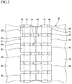
Fig. 2 ] An enlarged top view of elements in an engaged state as shown inFig. 1 . - [
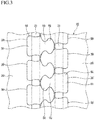
Fig. 3 ] An enlarged bottom view of elements in the engaged state as shown inFig. 2 . - [
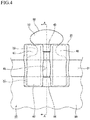
Fig. 4 ] A top view of an element. - [
Fig. 5 ] A bottom view of the element. - [
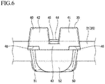
Fig. 6 ] A front view of the elementl. - [
Fig. 7 ] A sectional view taken along a line A-A inFig. 4 . - Hereinafter, a slide fastener employing one embodiment of a fastener stringer according to the present invention will be described in detail on the basis of the accompanying drawings. Meanwhile, in the following description, as for a slide fastener, an upper side refers to a near side with respect to the paper surface of
Fig. 1 ; a lower side refers to a far side with respect to the paper surface ofFig. 1 ; a front side refers to a upper side with respect to the paper surface ofFig. 1 ; a rear side refers to a lower side with respect to the paper surface ofFig. 1 ; a left side refers to a left side with respect to the paper surface ofFig. 1 ; and a right side refers to a right side with respect to the paper surface ofFig. 1 . Also, as for an element, an upper side refers to a near side with respect to the paper surface ofFig. 4 ; a lower side refers to a far side with respect to the paper surface ofFig. 4 ; a front side refers to a upper side with respect to the paper surface ofFig. 4 ; a rear side refers to a lower side with respect to the paper surface ofFig. 4 ; a left side refers to a left side with respect to the paper surface ofFig. 4 ; and a right side refers to a right side with respect to the paper surface ofFig. 4 . Further, a right and left direction is also referred to as a width direction. - First, a slide fastener SF employing a
fastener stringer 10 according to the present embodiment will be described. As shown inFig. 1 , the slide fastener SF includes a pair of right andleft tapes 20; a plurality ofelements 30 attached along each of opposing side edges of the right andleft tapes 20; aslider 11 for engaging and disengaging the right andleft elements 30 with and from each other;top end stops 12 attached, respectively, on upper end portions of the side edges of the right andleft tapes 20; and anopener 13 attached on lower ends of the side edges of the right andleft tapes 20. In addition, the right andleft tapes 20 and theelements 30 attached on each of the right andleft tapes 20 constitute thefastener stringer 10. Alternatively, theopener 13 may be replaced with bottom end stops. - As shown in
Figs. 2 and3 , thetape 20 is a band-shaped body having an upper surface and a lower surface and is provided with acore portion 21 along one side edge thereof. As shown inFig. 7 , thecore portion 21 is formed such that a thickness thereof in an upward and downward direction is greater than those of the other portions of thetape 20. Also, a plurality ofelements 30 is attached along thecore portion 21 of thetape 20. - As shown in
Figs. 2 to 7 , each of theelements 30 has anupper half portion 40 arranged on the upper surface of thetape 20 and alower half portion 50 arranged on the lower surface of thetape 20 and is attached on thetape 20 with the tape 20 (core portion 21) sandwiched therebetween. Theupper half portion 40 and thelower half portion 50 are formed to have substantially the same height dimension. Also, theelement 30 is made of synthetic resin or metal. - As shown in
Fig. 5 , thelower half portion 50 includes abase portion 51 configured to be attached on thetape 20; ahead portion 52 extending from thebase portion 51 toward theother tape 20 and configured to be engaged withelements 30 on the other side; and aneck portion 53 formed between thebase portion 51 and thehead portion 52 and having a width narrower than that of thehead portion 52. - As shown in
Figs. 4 ,6 and7 , theupper half portion 40 includes first and second dividedportions portion 43 connecting a front end portion of the first dividedportion 41 with a front end portion of the second dividedportion 42; and a second reinforcingportion 44 connecting a rear end portion of the first dividedportion 41 with a rear end portion of the second dividedportion 42. The first dividedportion 41 is provided at a front side in the tape length direction (the upper side inFig. 2 ) of theupper half portion 40 and the second dividedportion 42 is provided at a rear side in the tape length direction (the lower side inFig. 2 ) of theupper half portion 40. The first reinforcingportion 43 is provided to connect the front end portion of the first dividedportion 41 with the front end portion of the second dividedportion 42 and also to be connected to theneck portion 53 of thelower half portion 50. The second reinforcingportion 44 is provided to connect the rear end portion of the first dividedportion 41 with the rear end portion of the second dividedportion 42 and also to be positioned on thetape 20. - Each of the first and second divided
portions neck portion 53 of thelower half portion 50 while exposing thehead portion 52 as viewed in a top view of the element. Also, each of the first and second dividedportions lower half portion 50 at a part thereof, which is positioned in front of thecore portion 21 of thecorresponding tape 20. - Also, in the
upper half portion 40, anopening portion 45 opened upward is formed by the first dividedportion 41, the second dividedportion 42, the first reinforcingportion 43 and the second reinforcingportion 44, and thus thecore portion 21 of thetape 20 is exposed through theopening portion 45. That is, thetape 20 is exposed between the first dividedportion 41 and the second dividedportion 42. - Further, on a lower surface of the front end portion of each of the first and second divided
portions stepped portion 46 is formed to extend toward the inside of theneck portion 53 of thelower half portion 50 and also to be recessed upward. In an element-engaged state, an upper surface of thehead portion 52 of theelement 30 is arranged to face thestepped portions 46 of the elements 30 (i.e., lower surfaces of front end portions of first and second dividedportions 41, 42) on the other side. Also, when the fastener stringer 10 in the element-engaged state is curved to be convexed on an upper surface side thereof, a part of thehead portion 52 of theelement 30 on the other side enters thestepped portions 46, thereby enhancing flexibility of thefastener stringer 10 while maintaining engagement of theelements 30. - The first and second reinforcing
portions portion 43 is formed to have a rectangular cross-sectional shape, and the second reinforcingportion 44 is formed to have a circular arc-shaped cross-sectional shape. Alternatively, both the first and second reinforcingportions portion 43 may be formed to have a circular arc-shaped cross-sectional shape. Since the reinforcing portion is formed to have a circular arc-shaped cross-sectional shape, it is possible to make the first and second dividedportions portions - Further, according to the present embodiment, in order to maintain strength of the
element 30 while making the first and second dividedportions portion 43 and a height H2 of the second reinforcingportion 44 are set to 50% or less of a height H3 of theupper half portion 40, preferably, for example to 25% to 50% (seeFig. 7 ). Herein, each of the heights H1 to H3 is a height from a boundary position between theupper half portion 40 and thelower half portion 50 to the respective upper surfaces. Further, a width of the first and second reinforcingportions portions core portion 21 of thetape 20. - Further, according to the present embodiment, as shown in
Figs. 1 and2 , each of theelements 30 are arranged such that when elements are engaged with each other, first dividedportions 41 ofelements 30 of onetape 20 are respectively adjacent to second dividedportions 42 ofelements 30 of theother tape 20 and also are arrayed in a straight line shape along a tape width direction. - Further, according to the present embodiment, a distance between the first divided
portion 41 and the second dividedportion 42 of each of theelements 30 and also a distance betweenadjacent elements 30 are set such that the first dividedportions 41 and the second dividedportions 42 are arrayed at equal intervals along the tape length direction. - In the
fastener stringer 10 configured in this way, theupper half portion 40 of each of theelements 30 is divided into the first dividedportion 41 and the second dividedportion 42, thereby making oneelement 30 look like two narrower elements. Therefore, it is possible to make theelements 30 look as if a width thereof in the right and left direction is narrow. - Also, the first divided
portion 41 and the second dividedportion 42 are connected with each other by the first and second reinforcingportions portion 41 and the second dividedportion 42 are integrated with each other. Therefore, it is possible to enhance a coupling strength of the first and second dividedportions lower half portion 50 and thus to enhance strength of theelement 30. - Further, first divided
portions 41 ofelements 30 of onetape 20 are respectively adjacent to second dividedportions 42 ofelements 30 of theother tape 20 and also are arrayed in a straight line shape along the tape width direction. Further, the first dividedportions 41 and the second dividedportions 42 are arrayed at equal intervals along the tape length direction. When viewing the right and leftelements 30 in the engaged state considering together with the second reinforcingportions 44, the first dividedportions 41 and the second dividedportions 42 look as if they are connected with each other in a zigzag shape. - As set forth above, according to the
fastener stringer 10 of the present embodiment, theupper half portion 40 includes the first reinforcingportion 43 connecting the front end portion of the first dividedportion 41 with the front end portion of the second dividedportion 42 and the second reinforcingportion 44 connecting the rear end portion of the first dividedportion 41 with the rear end portion of the second dividedportion 42, and also thetape 20 is exposed between the first dividedportion 41 and the second dividedportion 42. Therefore, it is possible to enhance strength of theelements 30 while making theelements 30 look as if a width thereof in the right and left direction is narrow. - Also, according to the
fastener stringer 10 of the present embodiment, when elements are engaged with each other, first dividedportions 41 ofelements 30 of onetape 20 are respectively adjacent to second dividedportions 42 ofelements 30 of theother tape 20 and also are arrayed in a straight line shape along the tape width direction. Therefore, it is possible to enhance the aesthetic appearance of the slide fastener SF. - Further, according to the
fastener stringer 10 of the present embodiment, the second reinforcingportion 44 is formed to have a circular arc-shaped cross-sectional shape. Therefore it is possible to make the first and second dividedportions portion 44 invisible. - Further, according to the
fastener stringer 10 of the present embodiment the height H1 of the first reinforcingportion 43 and the height H2 of the second reinforcingportion 44 is set to 50% or less of the height H3 of theupper half portion 40. Therefore, it is possible to maintain strength of theelements 30 while making the first and second dividedportions - Further, according to the
fastener stringer 10 of the present embodiment, when viewing the right and leftelements 30 in the engaged state considering together with the second reinforcingportions 44, the first dividedportions 41 and the second dividedportions 42 look as if they are connected with each other in a zigzag shape. Therefore, it is possible to enhance the aesthetic appearance of the slide fastener SF. - Meanwhile, the present invention is not limited to the foregoing embodiments, but may be appropriately modified without departing from the spirit and scope of the present invention.
- For example, although two reinforcing portions, i.e., the first and second reinforcing portions are provided in the present embodiments, the present invention is not limited thereto. Only one of the first and second reinforcing portions may be provided.
- This application is based on a Vietnamese patent application (
1-2018-01982 -
- 10
- Fastener Stringer
- 20
- Tape
- 21
- Core Portion
- 30
- Element
- 40
- Upper Half Portion
- 41
- First Divided Portion
- 42
- Second Divided Portion
- 43
- First Reinforcing Portion
- 44
- Second Reinforcing Portion
- 45
- Opening Portion
- 46
- Step Portion
- 50
- Lower Half Portion
- 51
- Base Portion
- 52
- Head Portion
- 53
- Neck Portion
- H1
- Height of First Reinforcing Portion
- H2
- Height of Second Reinforcing Portion
- H3
- Height of Upper Half Portion
- SF
- Slide Fastener
Claims (5)
- A fastener stringer (10) comprising a pair of tapes (20) and a plurality of elements (30) attached along each of opposing side edges of the pair of tapes (20),
wherein each of the elements (30) comprises an upper half portion (40) arranged on an upper surface of each tape (20) and a lower half portion (50) arranged on a lower surface of the tape (20) and is attached on the tape (20) with the tape (20) sandwiched therebetween,
wherein the lower half portion (50) comprises a base portion (51) configured to be attached on the tape (20); a head portion (52) configured to be engaged with the elements (30) on the other side; and a neck portion (53) formed between the base portion (51) and the head portion (52),
wherein the upper half portion (40) comprises a first and second divided portions (41, 42) divided from each other in a tape length direction, and at least one reinforcing portion (43, 44) connecting the first divided portion (41) with the second divided portion (42),
wherein each of the first and second divided portions (41, 42) is arranged to cover the neck portion (53) of the lower half portion (50) while exposing the head portion (52) as viewed in a top view of the elements,
wherein the tape (20) is exposed between the first divided portion (41) and the second divided portion (42). - The fastener stringer (10) according to claim 1, wherein when the elements are engaged with each other, the first divided portions (41) of the elements (30) of one tape (20) are respectively adjacent to the second divided portions (42) of the elements (30) of the other tape (20) and also are arrayed in a straight line shape along a tape width direction.
- The fastener stringer (10) according to claim 1 or 2, wherein the at least one reinforcing portion is formed to have a circular arc-shaped cross-sectional shape.
- The fastener stringer (10) according to any one of claims 1 to 3, wherein the at least one reinforcing portion comprises a first reinforcing portion (43) connecting one end portion of the first divided portion (41) with one end portion of the second divided portion (42), and a second reinforcing portion (44) connecting the other end portion of the first divided portion (41) with the other end portion of the second divided portion (42).
- The fastener stringer (10) according to any one of claims 1 to 4, wherein the first divided portions (41) and the second divided portions (42) are arrayed at equal intervals along the tape length direction.
Applications Claiming Priority (2)
| Application Number | Priority Date | Filing Date | Title |
|---|---|---|---|
| VN201801982 | 2018-05-10 | ||
| PCT/JP2019/017816 WO2019216256A1 (en) | 2018-05-10 | 2019-04-25 | Fastener stringer |
Publications (3)
| Publication Number | Publication Date |
|---|---|
| EP3791747A1 true EP3791747A1 (en) | 2021-03-17 |
| EP3791747A4 EP3791747A4 (en) | 2021-06-30 |
| EP3791747B1 EP3791747B1 (en) | 2023-08-30 |
Family
ID=67296881
Family Applications (1)
| Application Number | Title | Priority Date | Filing Date |
|---|---|---|---|
| EP19799628.3A Active EP3791747B1 (en) | 2018-05-10 | 2019-04-25 | Fastener stringer |
Country Status (2)
| Country | Link |
|---|---|
| EP (1) | EP3791747B1 (en) |
| WO (1) | WO2019216256A1 (en) |
Families Citing this family (1)
| Publication number | Priority date | Publication date | Assignee | Title |
|---|---|---|---|---|
| JP7789945B2 (en) * | 2022-11-04 | 2025-12-22 | Ykk株式会社 | Slide fastener |
Family Cites Families (4)
| Publication number | Priority date | Publication date | Assignee | Title |
|---|---|---|---|---|
| IL161604A0 (en) * | 2004-04-25 | 2004-09-27 | Artzip Ltd | A zipper |
| EP2614742B1 (en) * | 2009-01-13 | 2017-09-06 | YKK Corporation | Slide fastener |
| CN103564993B (en) * | 2012-07-26 | 2016-05-04 | Ykk株式会社 | Slide fastener is with chain tooth and have the slide fastener of this chain tooth |
| CN206390415U (en) * | 2016-09-22 | 2017-08-11 | 曹昌文 | Shaped teeth for augmentation and modification of the tooth body and associated slide wedges and zippers |
-
2019
- 2019-04-25 WO PCT/JP2019/017816 patent/WO2019216256A1/en not_active Ceased
- 2019-04-25 EP EP19799628.3A patent/EP3791747B1/en active Active
Also Published As
| Publication number | Publication date |
|---|---|
| EP3791747A4 (en) | 2021-06-30 |
| EP3791747B1 (en) | 2023-08-30 |
| WO2019216256A1 (en) | 2019-11-14 |
Similar Documents
| Publication | Publication Date | Title |
|---|---|---|
| US9763498B2 (en) | Slider cover for slide fastener and slide fastener with slide cover | |
| CN106714609B (en) | Zipper elements, zipper strings and zippers | |
| US9968166B2 (en) | Slider cover for slide fastener | |
| EP2332435B1 (en) | Slide fastener | |
| EP2604138B1 (en) | Slide fastener | |
| EP3626099B1 (en) | Slide fastener | |
| EP2904922B1 (en) | Slide fastener | |
| CN102469852A (en) | Slide fastener | |
| JP3193160U (en) | Slider cover and slide fastener having the slider cover | |
| CN103209609A (en) | Sliding fastener | |
| TW201012410A (en) | Slider for slide fastener with automatic stopper | |
| JP4822187B2 (en) | Hidden slide fastener | |
| EP2848150B1 (en) | Slider for slide fastener | |
| US10765178B2 (en) | Element, fastener stringer, and slide fastener | |
| JPS5932329Y2 (en) | Slide fastener with release tool | |
| EP3791747B1 (en) | Fastener stringer | |
| KR100240220B1 (en) | Detachable bottom stop assembly for slide fastener | |
| JP2007236958A6 (en) | Hidden slide fastener | |
| EP1459643B1 (en) | Slide fastener with separable bottom end stop | |
| CN110037394B (en) | Zipper teeth chain belt | |
| KR100339142B1 (en) | Slider for slide fastener | |
| EP3516979A1 (en) | Slider and slide fastener | |
| CN105338851B (en) | Chain caps for zippers and long zipper chains | |
| WO2015071945A1 (en) | Fastener chain and slide fastener | |
| EP0187302A2 (en) | Slide fastener with a pair of intermeshable top end stops |
Legal Events
| Date | Code | Title | Description |
|---|---|---|---|
| STAA | Information on the status of an ep patent application or granted ep patent |
Free format text: STATUS: THE INTERNATIONAL PUBLICATION HAS BEEN MADE |
|
| PUAI | Public reference made under article 153(3) epc to a published international application that has entered the european phase |
Free format text: ORIGINAL CODE: 0009012 |
|
| STAA | Information on the status of an ep patent application or granted ep patent |
Free format text: STATUS: REQUEST FOR EXAMINATION WAS MADE |
|
| 17P | Request for examination filed |
Effective date: 20201106 |
|
| AK | Designated contracting states |
Kind code of ref document: A1 Designated state(s): AL AT BE BG CH CY CZ DE DK EE ES FI FR GB GR HR HU IE IS IT LI LT LU LV MC MK MT NL NO PL PT RO RS SE SI SK SM TR |
|
| AX | Request for extension of the european patent |
Extension state: BA ME |
|
| A4 | Supplementary search report drawn up and despatched |
Effective date: 20210531 |
|
| RIC1 | Information provided on ipc code assigned before grant |
Ipc: A44B 19/02 20060101AFI20210525BHEP Ipc: A44B 19/08 20060101ALI20210525BHEP Ipc: A44B 19/06 20060101ALI20210525BHEP |
|
| DAV | Request for validation of the european patent (deleted) | ||
| DAX | Request for extension of the european patent (deleted) | ||
| GRAP | Despatch of communication of intention to grant a patent |
Free format text: ORIGINAL CODE: EPIDOSNIGR1 |
|
| STAA | Information on the status of an ep patent application or granted ep patent |
Free format text: STATUS: GRANT OF PATENT IS INTENDED |
|
| INTG | Intention to grant announced |
Effective date: 20230421 |
|
| P01 | Opt-out of the competence of the unified patent court (upc) registered |
Effective date: 20230528 |
|
| GRAS | Grant fee paid |
Free format text: ORIGINAL CODE: EPIDOSNIGR3 |
|
| GRAA | (expected) grant |
Free format text: ORIGINAL CODE: 0009210 |
|
| STAA | Information on the status of an ep patent application or granted ep patent |
Free format text: STATUS: THE PATENT HAS BEEN GRANTED |
|
| AK | Designated contracting states |
Kind code of ref document: B1 Designated state(s): AL AT BE BG CH CY CZ DE DK EE ES FI FR GB GR HR HU IE IS IT LI LT LU LV MC MK MT NL NO PL PT RO RS SE SI SK SM TR |
|
| REG | Reference to a national code |
Ref country code: GB Ref legal event code: FG4D |
|
| REG | Reference to a national code |
Ref country code: CH Ref legal event code: EP |
|
| REG | Reference to a national code |
Ref country code: DE Ref legal event code: R096 Ref document number: 602019036281 Country of ref document: DE |
|
| REG | Reference to a national code |
Ref country code: IE Ref legal event code: FG4D |
|
| REG | Reference to a national code |
Ref country code: LT Ref legal event code: MG9D |
|
| REG | Reference to a national code |
Ref country code: NL Ref legal event code: MP Effective date: 20230830 |
|
| REG | Reference to a national code |
Ref country code: AT Ref legal event code: MK05 Ref document number: 1604238 Country of ref document: AT Kind code of ref document: T Effective date: 20230830 |
|
| PG25 | Lapsed in a contracting state [announced via postgrant information from national office to epo] |
Ref country code: GR Free format text: LAPSE BECAUSE OF FAILURE TO SUBMIT A TRANSLATION OF THE DESCRIPTION OR TO PAY THE FEE WITHIN THE PRESCRIBED TIME-LIMIT Effective date: 20231201 |
|
| PG25 | Lapsed in a contracting state [announced via postgrant information from national office to epo] |
Ref country code: IS Free format text: LAPSE BECAUSE OF FAILURE TO SUBMIT A TRANSLATION OF THE DESCRIPTION OR TO PAY THE FEE WITHIN THE PRESCRIBED TIME-LIMIT Effective date: 20231230 |
|
| PG25 | Lapsed in a contracting state [announced via postgrant information from national office to epo] |
Ref country code: SE Free format text: LAPSE BECAUSE OF FAILURE TO SUBMIT A TRANSLATION OF THE DESCRIPTION OR TO PAY THE FEE WITHIN THE PRESCRIBED TIME-LIMIT Effective date: 20230830 Ref country code: RS Free format text: LAPSE BECAUSE OF FAILURE TO SUBMIT A TRANSLATION OF THE DESCRIPTION OR TO PAY THE FEE WITHIN THE PRESCRIBED TIME-LIMIT Effective date: 20230830 Ref country code: NO Free format text: LAPSE BECAUSE OF FAILURE TO SUBMIT A TRANSLATION OF THE DESCRIPTION OR TO PAY THE FEE WITHIN THE PRESCRIBED TIME-LIMIT Effective date: 20231130 Ref country code: LV Free format text: LAPSE BECAUSE OF FAILURE TO SUBMIT A TRANSLATION OF THE DESCRIPTION OR TO PAY THE FEE WITHIN THE PRESCRIBED TIME-LIMIT Effective date: 20230830 Ref country code: LT Free format text: LAPSE BECAUSE OF FAILURE TO SUBMIT A TRANSLATION OF THE DESCRIPTION OR TO PAY THE FEE WITHIN THE PRESCRIBED TIME-LIMIT Effective date: 20230830 Ref country code: IS Free format text: LAPSE BECAUSE OF FAILURE TO SUBMIT A TRANSLATION OF THE DESCRIPTION OR TO PAY THE FEE WITHIN THE PRESCRIBED TIME-LIMIT Effective date: 20231230 Ref country code: HR Free format text: LAPSE BECAUSE OF FAILURE TO SUBMIT A TRANSLATION OF THE DESCRIPTION OR TO PAY THE FEE WITHIN THE PRESCRIBED TIME-LIMIT Effective date: 20230830 Ref country code: GR Free format text: LAPSE BECAUSE OF FAILURE TO SUBMIT A TRANSLATION OF THE DESCRIPTION OR TO PAY THE FEE WITHIN THE PRESCRIBED TIME-LIMIT Effective date: 20231201 Ref country code: FI Free format text: LAPSE BECAUSE OF FAILURE TO SUBMIT A TRANSLATION OF THE DESCRIPTION OR TO PAY THE FEE WITHIN THE PRESCRIBED TIME-LIMIT Effective date: 20230830 Ref country code: AT Free format text: LAPSE BECAUSE OF FAILURE TO SUBMIT A TRANSLATION OF THE DESCRIPTION OR TO PAY THE FEE WITHIN THE PRESCRIBED TIME-LIMIT Effective date: 20230830 |
|
| PG25 | Lapsed in a contracting state [announced via postgrant information from national office to epo] |
Ref country code: PL Free format text: LAPSE BECAUSE OF FAILURE TO SUBMIT A TRANSLATION OF THE DESCRIPTION OR TO PAY THE FEE WITHIN THE PRESCRIBED TIME-LIMIT Effective date: 20230830 Ref country code: NL Free format text: LAPSE BECAUSE OF FAILURE TO SUBMIT A TRANSLATION OF THE DESCRIPTION OR TO PAY THE FEE WITHIN THE PRESCRIBED TIME-LIMIT Effective date: 20230830 |
|
| PG25 | Lapsed in a contracting state [announced via postgrant information from national office to epo] |
Ref country code: ES Free format text: LAPSE BECAUSE OF FAILURE TO SUBMIT A TRANSLATION OF THE DESCRIPTION OR TO PAY THE FEE WITHIN THE PRESCRIBED TIME-LIMIT Effective date: 20230830 |
|
| PG25 | Lapsed in a contracting state [announced via postgrant information from national office to epo] |
Ref country code: SM Free format text: LAPSE BECAUSE OF FAILURE TO SUBMIT A TRANSLATION OF THE DESCRIPTION OR TO PAY THE FEE WITHIN THE PRESCRIBED TIME-LIMIT Effective date: 20230830 Ref country code: RO Free format text: LAPSE BECAUSE OF FAILURE TO SUBMIT A TRANSLATION OF THE DESCRIPTION OR TO PAY THE FEE WITHIN THE PRESCRIBED TIME-LIMIT Effective date: 20230830 Ref country code: ES Free format text: LAPSE BECAUSE OF FAILURE TO SUBMIT A TRANSLATION OF THE DESCRIPTION OR TO PAY THE FEE WITHIN THE PRESCRIBED TIME-LIMIT Effective date: 20230830 Ref country code: EE Free format text: LAPSE BECAUSE OF FAILURE TO SUBMIT A TRANSLATION OF THE DESCRIPTION OR TO PAY THE FEE WITHIN THE PRESCRIBED TIME-LIMIT Effective date: 20230830 Ref country code: DK Free format text: LAPSE BECAUSE OF FAILURE TO SUBMIT A TRANSLATION OF THE DESCRIPTION OR TO PAY THE FEE WITHIN THE PRESCRIBED TIME-LIMIT Effective date: 20230830 Ref country code: CZ Free format text: LAPSE BECAUSE OF FAILURE TO SUBMIT A TRANSLATION OF THE DESCRIPTION OR TO PAY THE FEE WITHIN THE PRESCRIBED TIME-LIMIT Effective date: 20230830 Ref country code: SK Free format text: LAPSE BECAUSE OF FAILURE TO SUBMIT A TRANSLATION OF THE DESCRIPTION OR TO PAY THE FEE WITHIN THE PRESCRIBED TIME-LIMIT Effective date: 20230830 Ref country code: PT Free format text: LAPSE BECAUSE OF FAILURE TO SUBMIT A TRANSLATION OF THE DESCRIPTION OR TO PAY THE FEE WITHIN THE PRESCRIBED TIME-LIMIT Effective date: 20240102 |
|
| PG25 | Lapsed in a contracting state [announced via postgrant information from national office to epo] |
Ref country code: IT Free format text: LAPSE BECAUSE OF FAILURE TO SUBMIT A TRANSLATION OF THE DESCRIPTION OR TO PAY THE FEE WITHIN THE PRESCRIBED TIME-LIMIT Effective date: 20230830 |
|
| REG | Reference to a national code |
Ref country code: DE Ref legal event code: R097 Ref document number: 602019036281 Country of ref document: DE |
|
| PLBE | No opposition filed within time limit |
Free format text: ORIGINAL CODE: 0009261 |
|
| STAA | Information on the status of an ep patent application or granted ep patent |
Free format text: STATUS: NO OPPOSITION FILED WITHIN TIME LIMIT |
|
| PG25 | Lapsed in a contracting state [announced via postgrant information from national office to epo] |
Ref country code: SI Free format text: LAPSE BECAUSE OF FAILURE TO SUBMIT A TRANSLATION OF THE DESCRIPTION OR TO PAY THE FEE WITHIN THE PRESCRIBED TIME-LIMIT Effective date: 20230830 |
|
| 26N | No opposition filed |
Effective date: 20240603 |
|
| PG25 | Lapsed in a contracting state [announced via postgrant information from national office to epo] |
Ref country code: BG Free format text: LAPSE BECAUSE OF FAILURE TO SUBMIT A TRANSLATION OF THE DESCRIPTION OR TO PAY THE FEE WITHIN THE PRESCRIBED TIME-LIMIT Effective date: 20230830 |
|
| PG25 | Lapsed in a contracting state [announced via postgrant information from national office to epo] |
Ref country code: MC Free format text: LAPSE BECAUSE OF FAILURE TO SUBMIT A TRANSLATION OF THE DESCRIPTION OR TO PAY THE FEE WITHIN THE PRESCRIBED TIME-LIMIT Effective date: 20230830 |
|
| PG25 | Lapsed in a contracting state [announced via postgrant information from national office to epo] |
Ref country code: MC Free format text: LAPSE BECAUSE OF FAILURE TO SUBMIT A TRANSLATION OF THE DESCRIPTION OR TO PAY THE FEE WITHIN THE PRESCRIBED TIME-LIMIT Effective date: 20230830 Ref country code: BG Free format text: LAPSE BECAUSE OF FAILURE TO SUBMIT A TRANSLATION OF THE DESCRIPTION OR TO PAY THE FEE WITHIN THE PRESCRIBED TIME-LIMIT Effective date: 20230830 |
|
| REG | Reference to a national code |
Ref country code: CH Ref legal event code: PL |
|
| PG25 | Lapsed in a contracting state [announced via postgrant information from national office to epo] |
Ref country code: LU Free format text: LAPSE BECAUSE OF NON-PAYMENT OF DUE FEES Effective date: 20240425 |
|
| GBPC | Gb: european patent ceased through non-payment of renewal fee |
Effective date: 20240425 |
|
| REG | Reference to a national code |
Ref country code: BE Ref legal event code: MM Effective date: 20240430 |
|
| PG25 | Lapsed in a contracting state [announced via postgrant information from national office to epo] |
Ref country code: LU Free format text: LAPSE BECAUSE OF NON-PAYMENT OF DUE FEES Effective date: 20240425 |
|
| PG25 | Lapsed in a contracting state [announced via postgrant information from national office to epo] |
Ref country code: BE Free format text: LAPSE BECAUSE OF NON-PAYMENT OF DUE FEES Effective date: 20240430 |
|
| PG25 | Lapsed in a contracting state [announced via postgrant information from national office to epo] |
Ref country code: GB Free format text: LAPSE BECAUSE OF NON-PAYMENT OF DUE FEES Effective date: 20240425 |
|
| PG25 | Lapsed in a contracting state [announced via postgrant information from national office to epo] |
Ref country code: FR Free format text: LAPSE BECAUSE OF NON-PAYMENT OF DUE FEES Effective date: 20240430 |
|
| PG25 | Lapsed in a contracting state [announced via postgrant information from national office to epo] |
Ref country code: GB Free format text: LAPSE BECAUSE OF NON-PAYMENT OF DUE FEES Effective date: 20240425 Ref country code: FR Free format text: LAPSE BECAUSE OF NON-PAYMENT OF DUE FEES Effective date: 20240430 Ref country code: BE Free format text: LAPSE BECAUSE OF NON-PAYMENT OF DUE FEES Effective date: 20240430 Ref country code: CH Free format text: LAPSE BECAUSE OF NON-PAYMENT OF DUE FEES Effective date: 20240430 |
|
| PG25 | Lapsed in a contracting state [announced via postgrant information from national office to epo] |
Ref country code: IE Free format text: LAPSE BECAUSE OF NON-PAYMENT OF DUE FEES Effective date: 20240425 |
|
| PGFP | Annual fee paid to national office [announced via postgrant information from national office to epo] |
Ref country code: DE Payment date: 20250305 Year of fee payment: 7 |
|
| PG25 | Lapsed in a contracting state [announced via postgrant information from national office to epo] |
Ref country code: CY Free format text: LAPSE BECAUSE OF FAILURE TO SUBMIT A TRANSLATION OF THE DESCRIPTION OR TO PAY THE FEE WITHIN THE PRESCRIBED TIME-LIMIT; INVALID AB INITIO Effective date: 20190425 |
|
| PG25 | Lapsed in a contracting state [announced via postgrant information from national office to epo] |
Ref country code: HU Free format text: LAPSE BECAUSE OF FAILURE TO SUBMIT A TRANSLATION OF THE DESCRIPTION OR TO PAY THE FEE WITHIN THE PRESCRIBED TIME-LIMIT; INVALID AB INITIO Effective date: 20190425 |