EP3791094B1 - Two-position gate and sprung gate valves having a full-flow open position and a restricted-flow open position - Google Patents
Two-position gate and sprung gate valves having a full-flow open position and a restricted-flow open position Download PDFInfo
- Publication number
- EP3791094B1 EP3791094B1 EP19800612.4A EP19800612A EP3791094B1 EP 3791094 B1 EP3791094 B1 EP 3791094B1 EP 19800612 A EP19800612 A EP 19800612A EP 3791094 B1 EP3791094 B1 EP 3791094B1
- Authority
- EP
- European Patent Office
- Prior art keywords
- gate
- flow
- restricted
- area
- exit
- Prior art date
- Legal status (The legal status is an assumption and is not a legal conclusion. Google has not performed a legal analysis and makes no representation as to the accuracy of the status listed.)
- Active
Links
Images







Classifications
-
- B—PERFORMING OPERATIONS; TRANSPORTING
- B60—VEHICLES IN GENERAL
- B60T—VEHICLE BRAKE CONTROL SYSTEMS OR PARTS THEREOF; BRAKE CONTROL SYSTEMS OR PARTS THEREOF, IN GENERAL; ARRANGEMENT OF BRAKING ELEMENTS ON VEHICLES IN GENERAL; PORTABLE DEVICES FOR PREVENTING UNWANTED MOVEMENT OF VEHICLES; VEHICLE MODIFICATIONS TO FACILITATE COOLING OF BRAKES
- B60T13/00—Transmitting braking action from initiating means to ultimate brake actuator with power assistance or drive; Brake systems incorporating such transmitting means, e.g. air-pressure brake systems
- B60T13/10—Transmitting braking action from initiating means to ultimate brake actuator with power assistance or drive; Brake systems incorporating such transmitting means, e.g. air-pressure brake systems with fluid assistance, drive, or release
- B60T13/24—Transmitting braking action from initiating means to ultimate brake actuator with power assistance or drive; Brake systems incorporating such transmitting means, e.g. air-pressure brake systems with fluid assistance, drive, or release the fluid being gaseous
- B60T13/46—Vacuum systems
- B60T13/52—Vacuum systems indirect, i.e. vacuum booster units
- B60T13/57—Vacuum systems indirect, i.e. vacuum booster units characterised by constructional features of control valves
-
- B—PERFORMING OPERATIONS; TRANSPORTING
- B60—VEHICLES IN GENERAL
- B60T—VEHICLE BRAKE CONTROL SYSTEMS OR PARTS THEREOF; BRAKE CONTROL SYSTEMS OR PARTS THEREOF, IN GENERAL; ARRANGEMENT OF BRAKING ELEMENTS ON VEHICLES IN GENERAL; PORTABLE DEVICES FOR PREVENTING UNWANTED MOVEMENT OF VEHICLES; VEHICLE MODIFICATIONS TO FACILITATE COOLING OF BRAKES
- B60T15/00—Construction arrangement, or operation of valves incorporated in power brake systems and not covered by groups B60T11/00 or B60T13/00
- B60T15/02—Application and release valves
- B60T15/025—Electrically controlled valves
- B60T15/027—Electrically controlled valves in pneumatic systems
-
- F—MECHANICAL ENGINEERING; LIGHTING; HEATING; WEAPONS; BLASTING
- F02—COMBUSTION ENGINES; HOT-GAS OR COMBUSTION-PRODUCT ENGINE PLANTS
- F02B—INTERNAL-COMBUSTION PISTON ENGINES; COMBUSTION ENGINES IN GENERAL
- F02B37/00—Engines characterised by provision of pumps driven at least for part of the time by exhaust
- F02B37/12—Control of the pumps
- F02B37/16—Control of the pumps by bypassing charging air
-
- F—MECHANICAL ENGINEERING; LIGHTING; HEATING; WEAPONS; BLASTING
- F02—COMBUSTION ENGINES; HOT-GAS OR COMBUSTION-PRODUCT ENGINE PLANTS
- F02M—SUPPLYING COMBUSTION ENGINES IN GENERAL WITH COMBUSTIBLE MIXTURES OR CONSTITUENTS THEREOF
- F02M35/00—Combustion-air cleaners, air intakes, intake silencers, or induction systems specially adapted for, or arranged on, internal-combustion engines
- F02M35/10—Air intakes; Induction systems
- F02M35/10209—Fluid connections to the air intake system; their arrangement of pipes, valves or the like
- F02M35/10229—Fluid connections to the air intake system; their arrangement of pipes, valves or the like the intake system acting as a vacuum or overpressure source for auxiliary devices, e.g. brake systems; Vacuum chambers
-
- F—MECHANICAL ENGINEERING; LIGHTING; HEATING; WEAPONS; BLASTING
- F02—COMBUSTION ENGINES; HOT-GAS OR COMBUSTION-PRODUCT ENGINE PLANTS
- F02M—SUPPLYING COMBUSTION ENGINES IN GENERAL WITH COMBUSTIBLE MIXTURES OR CONSTITUENTS THEREOF
- F02M63/00—Other fuel-injection apparatus having pertinent characteristics not provided for in groups F02M39/00 - F02M57/00 or F02M67/00; Details, component parts, or accessories of fuel-injection apparatus, not provided for in, or of interest apart from, the apparatus of groups F02M39/00 - F02M61/00 or F02M67/00; Combination of fuel pump with other devices, e.g. lubricating oil pump
- F02M63/0012—Valves
- F02M63/0031—Valves characterized by the type of valves, e.g. special valve member details, valve seat details, valve housing details
- F02M63/0043—Two-way valves
-
- F—MECHANICAL ENGINEERING; LIGHTING; HEATING; WEAPONS; BLASTING
- F02—COMBUSTION ENGINES; HOT-GAS OR COMBUSTION-PRODUCT ENGINE PLANTS
- F02M—SUPPLYING COMBUSTION ENGINES IN GENERAL WITH COMBUSTIBLE MIXTURES OR CONSTITUENTS THEREOF
- F02M63/00—Other fuel-injection apparatus having pertinent characteristics not provided for in groups F02M39/00 - F02M57/00 or F02M67/00; Details, component parts, or accessories of fuel-injection apparatus, not provided for in, or of interest apart from, the apparatus of groups F02M39/00 - F02M61/00 or F02M67/00; Combination of fuel pump with other devices, e.g. lubricating oil pump
- F02M63/0012—Valves
- F02M63/0059—Arrangements of valve actuators
- F02M63/0068—Actuators specially adapted for partial and full opening of the valves
-
- F—MECHANICAL ENGINEERING; LIGHTING; HEATING; WEAPONS; BLASTING
- F02—COMBUSTION ENGINES; HOT-GAS OR COMBUSTION-PRODUCT ENGINE PLANTS
- F02M—SUPPLYING COMBUSTION ENGINES IN GENERAL WITH COMBUSTIBLE MIXTURES OR CONSTITUENTS THEREOF
- F02M63/00—Other fuel-injection apparatus having pertinent characteristics not provided for in groups F02M39/00 - F02M57/00 or F02M67/00; Details, component parts, or accessories of fuel-injection apparatus, not provided for in, or of interest apart from, the apparatus of groups F02M39/00 - F02M61/00 or F02M67/00; Combination of fuel pump with other devices, e.g. lubricating oil pump
- F02M63/02—Fuel-injection apparatus having several injectors fed by a common pumping element, or having several pumping elements feeding a common injector; Fuel-injection apparatus having provisions for cutting-out pumps, pumping elements, or injectors; Fuel-injection apparatus having provisions for variably interconnecting pumping elements and injectors alternatively
- F02M63/0225—Fuel-injection apparatus having a common rail feeding several injectors ; Means for varying pressure in common rails; Pumps feeding common rails
- F02M63/023—Means for varying pressure in common rails
- F02M63/0235—Means for varying pressure in common rails by bleeding fuel pressure
- F02M63/025—Means for varying pressure in common rails by bleeding fuel pressure from the common rail
-
- F—MECHANICAL ENGINEERING; LIGHTING; HEATING; WEAPONS; BLASTING
- F16—ENGINEERING ELEMENTS AND UNITS; GENERAL MEASURES FOR PRODUCING AND MAINTAINING EFFECTIVE FUNCTIONING OF MACHINES OR INSTALLATIONS; THERMAL INSULATION IN GENERAL
- F16K—VALVES; TAPS; COCKS; ACTUATING-FLOATS; DEVICES FOR VENTING OR AERATING
- F16K3/00—Gate valves or sliding valves, i.e. cut-off apparatus with closing members having a sliding movement along the seat for opening and closing
- F16K3/02—Gate valves or sliding valves, i.e. cut-off apparatus with closing members having a sliding movement along the seat for opening and closing with flat sealing faces; Packings therefor
-
- F—MECHANICAL ENGINEERING; LIGHTING; HEATING; WEAPONS; BLASTING
- F16—ENGINEERING ELEMENTS AND UNITS; GENERAL MEASURES FOR PRODUCING AND MAINTAINING EFFECTIVE FUNCTIONING OF MACHINES OR INSTALLATIONS; THERMAL INSULATION IN GENERAL
- F16K—VALVES; TAPS; COCKS; ACTUATING-FLOATS; DEVICES FOR VENTING OR AERATING
- F16K3/00—Gate valves or sliding valves, i.e. cut-off apparatus with closing members having a sliding movement along the seat for opening and closing
- F16K3/02—Gate valves or sliding valves, i.e. cut-off apparatus with closing members having a sliding movement along the seat for opening and closing with flat sealing faces; Packings therefor
- F16K3/0227—Packings
-
- F—MECHANICAL ENGINEERING; LIGHTING; HEATING; WEAPONS; BLASTING
- F16—ENGINEERING ELEMENTS AND UNITS; GENERAL MEASURES FOR PRODUCING AND MAINTAINING EFFECTIVE FUNCTIONING OF MACHINES OR INSTALLATIONS; THERMAL INSULATION IN GENERAL
- F16K—VALVES; TAPS; COCKS; ACTUATING-FLOATS; DEVICES FOR VENTING OR AERATING
- F16K3/00—Gate valves or sliding valves, i.e. cut-off apparatus with closing members having a sliding movement along the seat for opening and closing
- F16K3/30—Details
-
- F—MECHANICAL ENGINEERING; LIGHTING; HEATING; WEAPONS; BLASTING
- F16—ENGINEERING ELEMENTS AND UNITS; GENERAL MEASURES FOR PRODUCING AND MAINTAINING EFFECTIVE FUNCTIONING OF MACHINES OR INSTALLATIONS; THERMAL INSULATION IN GENERAL
- F16K—VALVES; TAPS; COCKS; ACTUATING-FLOATS; DEVICES FOR VENTING OR AERATING
- F16K31/00—Actuating devices; Operating means; Releasing devices
- F16K31/12—Actuating devices; Operating means; Releasing devices actuated by fluid
- F16K31/126—Actuating devices; Operating means; Releasing devices actuated by fluid the fluid acting on a diaphragm, bellows, or the like
Definitions
- a two-position gate valve that has a gate defining a full-flow passageway therethrough and defining a restricted-flow passageway therethrough, without defining a closed position.
- the two-position gate valve includes a conduit separated into a first section and a second section by a pocket in which the gate is linearly translatable by an actuator to which it is operatively connected for movement between a full-flow position and a restricted-flow position.
- the full-flow passageway has an entrance with a first area and an exit with a second area, the second area being smaller than the first area, and the full-flow passageway continuously tapers from the entrance to the exit thereof.
- the restricted-flow passageway has an entrance with a third area and has an exit with a fourth area, the fourth area being smaller than the first area, the second area, and the third area, and the restricted-flow passageway continuously tapers from the entrance to the exit thereof.
- Flow through the full-flow passageway is in a first direction and flow through the restricted-flow passageway is also in the first direction, and the ratio of the fourth area to the second area is in a range of 5 to 15.
- a two-position gate valve that has a spring gate assembly defining a full-flow passageway therethrough and defining a restricted-flow passageway therethrough, without defining a closed position.
- the two-position gate valve includes a conduit separated into a first section and a second section by a pocket in which the gate is linearly translatable by an actuator to which it is operatively connected for movement between a full-flow position and a restricted-flow position.
- the endless elastic band is sandwiched between the first and second gate members with the full-flow passageway and the restricted flow passageway received within the open space thereof.
- the first and second gate members collectively define a full-open position and a restricted-flow position, without defining a closed position. Flow through the full-flow passageway is in a first direction and flow through the restricted-flow passageway is also in the first direction.
- the first and second elongate throats each have a length smaller than the distance from an exterior surface of the second gate member to an exterior surface of the first gate member, thereby defining a clearance gap at the terminus of each of the first and second elongate throats.
- the clearance gap is at least 0.5 mm less than a length of the flange of either of the full-flow exit or the restricted flow exit.
- fluid means any liquid, suspension, colloid, gas, plasma, or combinations thereof.
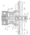
- FIGS. 1-3 illustrate one embodiment of a gate valve 100 adapted to selectively control the flow of a fluid, for example, air flowing from an intake to a brake vacuum boost system.
- the gate valve 100 may have a housing 102 containing an actuator 103 having a solenoid coil 104 and an armature 106 connectable to a valve mechanism 120.
- the armature 106 includes an insertion end 106a received within the solenoid coil 104 and an adjoining body portion 107 that is more fully received within the solenoid coil upon the application of an electrical current to the coil.
- the insertion end 106a and body portion 107 may be cylinders manufactured from a magnetic or paramagnetic material, for example an iron-containing alloy or a ferritecontaining composite material.
- the biasing element 110 may be a coil spring 112 surrounding the body portion 107 of the armature 106 and abutting both the solenoid coil 104 and a non-insertion end 106b, but it will be appreciated that the biasing element could be a diaphragm or flat spring abutting or coupled to the non-insertion end, a leaf spring abutting or coupled to the non-insertion end, etc.
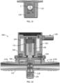
- FIG. 22 another embodiment of a gate valve is shown that includes the biasing element 110 received in a bore 111 within the body portion 107 of the armature 106.
- the solenoid may instead be a bistable solenoid including other biasing elements.
- the multi-part socket 268 snaps around the head 167 of the stem 114 of the mechanical coupling as shown in FIG. 22 .
- the multi-part socket 268 assists in the assembly of the sprung gate assembly 228' (or 128, 228, etc.) by actively retaining the assembly upon the stem 114 prior to insertion within the pocket 126.
- the larger chamber 274 is typically larger than the plate-like head 167 of the stem 114, thereby providing clearance for the sprung gate assembly to rotate about the stem 114. As mentioned above, this is advantageous because the spring gate assembly 228', 428 will be free to rotate 360 degrees or more relative to the stem 114 during assembly.
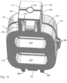
- a fifth embodiment of a sprung gate assembly is provided, which similarly includes a first gate member 430, a second gate member 432, and an endless elastic band 434, as described with respect to FIGS. 18 and 19 herein, received between the first and second gate members 430, 432.
- the endless elastic band 434 may be described as being sandwiched between the first and second gate members 430, 432.
- the general construction of the first and second gate members 430, 432 corresponds to the construction described with respect to FIGS. 10 and 11 .
- This plug 453 fits within the dimensions of the second open space defined by the endless elastic band 434 and is dimensioned to be at least the size of the second opening 444 in the first gate member 430, which defines a smaller opening than a corresponding inner perimeter of the endless elastic band 434.
- the plug 453 may be a substantially smooth portion of the interior surface 452 of the second gate member 432.
- the housing 502 includes a flange 504 for connecting the housing to the valve mechanism 120, in particular to the conduit 122.
- An airtight seal is desirable between these two components and is accomplished herein by spin welding the flange 504 of the housing 502 to a mating flange 506 of the conduit.
- the conduit includes the mating flange 504, which is a generally annular flange disposed about the connection opening 124 of the pocket 126.
- the flange 504 of the housing 502 may have either a generally V- or W-shaped cross-sectional profile and the mating flange 506 of the conduit 122 has the opposite profile relative thereto. For example, as shown in FIG.
- FIGS. 25A-25C comparative simulations of the flow through the sprung gate of FIG. 20 , FIG. 23, and FIG. 24 are provided. Red designates the fastest flow within the conduit through the sprung gate, and light blue represents the slowest flow within the conduit.
- FIG. 25A had a flow of 9.8 g/s.
- FIG. 25B had a flow of 9.0 g/s.
- FIG. 25C had a flow of 10.1 g/s. Accordingly, the continuous passages of the sprung gates illustrated in FIGS. 23 and 24 have comparable flow to that of FIG. 20 , and the sprung gate of FIG. 24 even experienced an improvement of 0.3 g/s. As such, these alternate embodiments can reduce debris ingress without sacrificing performance of the valve.
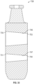
- the tapering interior passageway 550 has a two-fold purpose; it enables the easy removal of the part from the forming tool, and it ensures that when the gate 528 is in the flow condition that the flow entrance 536 does not interfere with the flow.
- the continuous gradual taper of the tapering interior passageway 550 is such that the opening height H at the flow entrance 536 is about 0.1 mm to about 0.5 mm greater than the worst-case travel of the gate.
- the opening height H is larger than the portion of the valve opening 123 of the conduit 122 that is most proximate thereto.
- Each elongate throat 642, 643 solve the problem of debris ingress in between moving and stationary surfaces of the sprung gate with minimal to no reduction in the flow capacity of the sprung gate.
- Each elongate throat 642, 643 defines a gradually, continuously tapering interior passageway 646, 647.
- Each tapering interior passageway 646,647 reduces in dimension gradually, continuously toward its terminus or distal end 645, 652, but the restricted-flow passageway 647 tapers with a greater slope, as viewed in a longitudinal cross-section, than the full-flow passageway.
- the second area of the first exit 649 is smaller than the first area of the first entrance 631.
- first entrance 631 of the restricted-flow passageway 647 is generally rectangularly-shaped with a longitudinal axis thereof oriented transverse to the flow direction and the first exit 649, 649' of the restricted-flow passage is oval-shaped with a major axis A M thereof oriented transverse to the flow direction.
- the second entrance 635 and the second exit 653 of the full-flow passageway 646 are both generally rectangularly-shaped with a longitudinal axis A L of each oriented transverse to the flow direction.
- the first entrance 631 and the second exit 649 of the restricted-flow passageway 647 are both generally rectangularly-shaped with a longitudinal axis of each oriented transverse to the flow direction.
- first and second entrances and the first and second exits are as described above for the second gate members 632, 632'.
- the direction of flow through the full-flow passageway is in a first direction and flow through the restricted-flow passageway is also in the first direction.
Landscapes
- Engineering & Computer Science (AREA)
- General Engineering & Computer Science (AREA)
- Mechanical Engineering (AREA)
- Chemical & Material Sciences (AREA)
- Combustion & Propulsion (AREA)
- Transportation (AREA)
- Sliding Valves (AREA)
- Magnetically Actuated Valves (AREA)
- Characterised By The Charging Evacuation (AREA)
Applications Claiming Priority (2)
| Application Number | Priority Date | Filing Date | Title |
|---|---|---|---|
| US201862667870P | 2018-05-07 | 2018-05-07 | |
| PCT/US2019/031074 WO2019217389A1 (en) | 2018-05-07 | 2019-05-07 | Two-position gate and sprung gate valves having a full-flow open position and a restricted-flow open position |
Publications (3)
| Publication Number | Publication Date |
|---|---|
| EP3791094A1 EP3791094A1 (en) | 2021-03-17 |
| EP3791094A4 EP3791094A4 (en) | 2021-12-08 |
| EP3791094B1 true EP3791094B1 (en) | 2024-07-10 |
Family
ID=68384896
Family Applications (1)
| Application Number | Title | Priority Date | Filing Date |
|---|---|---|---|
| EP19800612.4A Active EP3791094B1 (en) | 2018-05-07 | 2019-05-07 | Two-position gate and sprung gate valves having a full-flow open position and a restricted-flow open position |
Country Status (6)
| Country | Link |
|---|---|
| US (1) | US10830197B2 (https=) |
| EP (1) | EP3791094B1 (https=) |
| JP (1) | JP7160944B2 (https=) |
| KR (1) | KR102451830B1 (https=) |
| CN (1) | CN112135992B (https=) |
| WO (1) | WO2019217389A1 (https=) |
Families Citing this family (3)
| Publication number | Priority date | Publication date | Assignee | Title |
|---|---|---|---|---|
| US12366030B2 (en) * | 2022-07-06 | 2025-07-22 | Whirlpool Corporation | Laundry machine |
| CA3233583A1 (en) * | 2023-03-27 | 2025-06-23 | Edge Mechanical Design Inc. | Gate valve with novel seal and sealing arrangement |
| JP2025034649A (ja) | 2023-08-31 | 2025-03-13 | サンデン・リテールシステム株式会社 | 飲料供給装置の原材料キャニスタ |
Family Cites Families (13)
| Publication number | Priority date | Publication date | Assignee | Title |
|---|---|---|---|---|
| US2858851A (en) * | 1954-09-16 | 1958-11-04 | James W F Holl | Push-pull valve |
| US3494377A (en) * | 1967-06-12 | 1970-02-10 | Fmc Corp | Gate valve mechanism for control of plural passages |
| US3955591A (en) * | 1975-03-05 | 1976-05-11 | Baumann Hans D | Insert type sliding gate valve |
| US4671312A (en) * | 1984-05-14 | 1987-06-09 | Axelson, Inc. | Wireline cutting actuator and valve |
| US5236345A (en) * | 1992-02-11 | 1993-08-17 | Nevrekar Venkatesh R | Expanding gate valve assembly |
| JP3951885B2 (ja) | 2002-10-22 | 2007-08-01 | 日産自動車株式会社 | 燃料電池システム |
| US8539827B2 (en) | 2011-01-31 | 2013-09-24 | Badger Meter, Inc. | Water meter with integral flow restriction valve |
| KR102077886B1 (ko) * | 2013-08-30 | 2020-04-07 | 데이코 아이피 홀딩스 엘엘시 | 솔레노이드 액츄에이터에 의해 이동가능한 탄성 게이트 밸브 |
| US10221867B2 (en) | 2013-12-10 | 2019-03-05 | Dayco Ip Holdings, Llc | Flow control for aspirators producing vacuum using the venturi effect |
| EP3094897B1 (en) * | 2013-12-11 | 2018-10-24 | Dayco IP Holdings, LLC | Solenoid-powered gate valve |
| EP3090159B1 (en) * | 2013-12-11 | 2019-05-22 | Dayco IP Holdings, LLC | Turbocharger compressor recirculation system |
| US9599234B1 (en) * | 2015-12-07 | 2017-03-21 | Dayco Ip Holdings, Llc | Sprung gate valve |
| CN107956902B (zh) * | 2017-10-27 | 2024-05-03 | 江西省唯欣高科油压科技股份有限公司 | 节流阀 |
-
2019
- 2019-05-07 US US16/405,183 patent/US10830197B2/en active Active
- 2019-05-07 EP EP19800612.4A patent/EP3791094B1/en active Active
- 2019-05-07 JP JP2020562731A patent/JP7160944B2/ja active Active
- 2019-05-07 CN CN201980030757.6A patent/CN112135992B/zh active Active
- 2019-05-07 WO PCT/US2019/031074 patent/WO2019217389A1/en not_active Ceased
- 2019-05-07 KR KR1020207032144A patent/KR102451830B1/ko active Active
Also Published As
| Publication number | Publication date |
|---|---|
| EP3791094A4 (en) | 2021-12-08 |
| US20190338741A1 (en) | 2019-11-07 |
| WO2019217389A1 (en) | 2019-11-14 |
| EP3791094A1 (en) | 2021-03-17 |
| JP2021523331A (ja) | 2021-09-02 |
| US10830197B2 (en) | 2020-11-10 |
| JP7160944B2 (ja) | 2022-10-25 |
| BR112020022696A2 (pt) | 2021-02-09 |
| KR102451830B1 (ko) | 2022-10-06 |
| CN112135992B (zh) | 2022-11-01 |
| KR20210006366A (ko) | 2021-01-18 |
| CN112135992A (zh) | 2020-12-25 |
Similar Documents
| Publication | Publication Date | Title |
|---|---|---|
| EP3039319B1 (en) | Sprung gate valves movable by a solenoid actuator | |
| EP3387299B1 (en) | Sprung gate valve | |
| US9574677B2 (en) | Solenoid-powered gate valve | |
| US11067177B2 (en) | Sprung gate valves movable by an actuator | |
| EP3791094B1 (en) | Two-position gate and sprung gate valves having a full-flow open position and a restricted-flow open position | |
| EP3094897B1 (en) | Solenoid-powered gate valve | |
| BR112020022696B1 (pt) | Válvulas de gaveta com mola, de duas posições, tendo uma posição aberta para fluxo completo e uma posição aberta para fluxo restrito |
Legal Events
| Date | Code | Title | Description |
|---|---|---|---|
| STAA | Information on the status of an ep patent application or granted ep patent |
Free format text: STATUS: THE INTERNATIONAL PUBLICATION HAS BEEN MADE |
|
| PUAI | Public reference made under article 153(3) epc to a published international application that has entered the european phase |
Free format text: ORIGINAL CODE: 0009012 |
|
| STAA | Information on the status of an ep patent application or granted ep patent |
Free format text: STATUS: REQUEST FOR EXAMINATION WAS MADE |
|
| 17P | Request for examination filed |
Effective date: 20201203 |
|
| AK | Designated contracting states |
Kind code of ref document: A1 Designated state(s): AL AT BE BG CH CY CZ DE DK EE ES FI FR GB GR HR HU IE IS IT LI LT LU LV MC MK MT NL NO PL PT RO RS SE SI SK SM TR |
|
| AX | Request for extension of the european patent |
Extension state: BA ME |
|
| DAV | Request for validation of the european patent (deleted) | ||
| DAX | Request for extension of the european patent (deleted) | ||
| A4 | Supplementary search report drawn up and despatched |
Effective date: 20211105 |
|
| RIC1 | Information provided on ipc code assigned before grant |
Ipc: F16K 27/04 20060101ALI20211029BHEP Ipc: F16K 3/314 20060101ALI20211029BHEP Ipc: F16K 3/00 20060101ALI20211029BHEP Ipc: F16K 3/02 20060101AFI20211029BHEP |
|
| RAP3 | Party data changed (applicant data changed or rights of an application transferred) |
Owner name: DAYCO IP HOLDINGS, LLC |
|
| P01 | Opt-out of the competence of the unified patent court (upc) registered |
Effective date: 20230522 |
|
| GRAP | Despatch of communication of intention to grant a patent |
Free format text: ORIGINAL CODE: EPIDOSNIGR1 |
|
| STAA | Information on the status of an ep patent application or granted ep patent |
Free format text: STATUS: GRANT OF PATENT IS INTENDED |
|
| INTG | Intention to grant announced |
Effective date: 20240105 |
|
| GRAS | Grant fee paid |
Free format text: ORIGINAL CODE: EPIDOSNIGR3 |
|
| GRAA | (expected) grant |
Free format text: ORIGINAL CODE: 0009210 |
|
| STAA | Information on the status of an ep patent application or granted ep patent |
Free format text: STATUS: THE PATENT HAS BEEN GRANTED |
|
| AK | Designated contracting states |
Kind code of ref document: B1 Designated state(s): AL AT BE BG CH CY CZ DE DK EE ES FI FR GB GR HR HU IE IS IT LI LT LU LV MC MK MT NL NO PL PT RO RS SE SI SK SM TR |
|
| REG | Reference to a national code |
Ref country code: CH Ref legal event code: EP |
|
| REG | Reference to a national code |
Ref country code: DE Ref legal event code: R096 Ref document number: 602019055045 Country of ref document: DE |
|
| REG | Reference to a national code |
Ref country code: LT Ref legal event code: MG9D |
|
| REG | Reference to a national code |
Ref country code: NL Ref legal event code: MP Effective date: 20240710 |
|
| PG25 | Lapsed in a contracting state [announced via postgrant information from national office to epo] |
Ref country code: PT Free format text: LAPSE BECAUSE OF FAILURE TO SUBMIT A TRANSLATION OF THE DESCRIPTION OR TO PAY THE FEE WITHIN THE PRESCRIBED TIME-LIMIT Effective date: 20241111 |
|
| REG | Reference to a national code |
Ref country code: AT Ref legal event code: MK05 Ref document number: 1702284 Country of ref document: AT Kind code of ref document: T Effective date: 20240710 |
|
| PG25 | Lapsed in a contracting state [announced via postgrant information from national office to epo] |
Ref country code: NL Free format text: LAPSE BECAUSE OF FAILURE TO SUBMIT A TRANSLATION OF THE DESCRIPTION OR TO PAY THE FEE WITHIN THE PRESCRIBED TIME-LIMIT Effective date: 20240710 |
|
| PG25 | Lapsed in a contracting state [announced via postgrant information from national office to epo] |
Ref country code: PT Free format text: LAPSE BECAUSE OF FAILURE TO SUBMIT A TRANSLATION OF THE DESCRIPTION OR TO PAY THE FEE WITHIN THE PRESCRIBED TIME-LIMIT Effective date: 20241111 Ref country code: NL Free format text: LAPSE BECAUSE OF FAILURE TO SUBMIT A TRANSLATION OF THE DESCRIPTION OR TO PAY THE FEE WITHIN THE PRESCRIBED TIME-LIMIT Effective date: 20240710 |
|
| PG25 | Lapsed in a contracting state [announced via postgrant information from national office to epo] |
Ref country code: NO Free format text: LAPSE BECAUSE OF FAILURE TO SUBMIT A TRANSLATION OF THE DESCRIPTION OR TO PAY THE FEE WITHIN THE PRESCRIBED TIME-LIMIT Effective date: 20241010 |
|
| PG25 | Lapsed in a contracting state [announced via postgrant information from national office to epo] |
Ref country code: GR Free format text: LAPSE BECAUSE OF FAILURE TO SUBMIT A TRANSLATION OF THE DESCRIPTION OR TO PAY THE FEE WITHIN THE PRESCRIBED TIME-LIMIT Effective date: 20241011 Ref country code: FI Free format text: LAPSE BECAUSE OF FAILURE TO SUBMIT A TRANSLATION OF THE DESCRIPTION OR TO PAY THE FEE WITHIN THE PRESCRIBED TIME-LIMIT Effective date: 20240710 Ref country code: PL Free format text: LAPSE BECAUSE OF FAILURE TO SUBMIT A TRANSLATION OF THE DESCRIPTION OR TO PAY THE FEE WITHIN THE PRESCRIBED TIME-LIMIT Effective date: 20240710 |
|
| PG25 | Lapsed in a contracting state [announced via postgrant information from national office to epo] |
Ref country code: BG Free format text: LAPSE BECAUSE OF FAILURE TO SUBMIT A TRANSLATION OF THE DESCRIPTION OR TO PAY THE FEE WITHIN THE PRESCRIBED TIME-LIMIT Effective date: 20240710 |
|
| PG25 | Lapsed in a contracting state [announced via postgrant information from national office to epo] |
Ref country code: LV Free format text: LAPSE BECAUSE OF FAILURE TO SUBMIT A TRANSLATION OF THE DESCRIPTION OR TO PAY THE FEE WITHIN THE PRESCRIBED TIME-LIMIT Effective date: 20240710 |
|
| PG25 | Lapsed in a contracting state [announced via postgrant information from national office to epo] |
Ref country code: AT Free format text: LAPSE BECAUSE OF FAILURE TO SUBMIT A TRANSLATION OF THE DESCRIPTION OR TO PAY THE FEE WITHIN THE PRESCRIBED TIME-LIMIT Effective date: 20240710 Ref country code: IS Free format text: LAPSE BECAUSE OF FAILURE TO SUBMIT A TRANSLATION OF THE DESCRIPTION OR TO PAY THE FEE WITHIN THE PRESCRIBED TIME-LIMIT Effective date: 20241110 |
|
| PG25 | Lapsed in a contracting state [announced via postgrant information from national office to epo] |
Ref country code: HR Free format text: LAPSE BECAUSE OF FAILURE TO SUBMIT A TRANSLATION OF THE DESCRIPTION OR TO PAY THE FEE WITHIN THE PRESCRIBED TIME-LIMIT Effective date: 20240710 |
|
| PG25 | Lapsed in a contracting state [announced via postgrant information from national office to epo] |
Ref country code: ES Free format text: LAPSE BECAUSE OF FAILURE TO SUBMIT A TRANSLATION OF THE DESCRIPTION OR TO PAY THE FEE WITHIN THE PRESCRIBED TIME-LIMIT Effective date: 20240710 Ref country code: RS Free format text: LAPSE BECAUSE OF FAILURE TO SUBMIT A TRANSLATION OF THE DESCRIPTION OR TO PAY THE FEE WITHIN THE PRESCRIBED TIME-LIMIT Effective date: 20241010 |
|
| PG25 | Lapsed in a contracting state [announced via postgrant information from national office to epo] |
Ref country code: RS Free format text: LAPSE BECAUSE OF FAILURE TO SUBMIT A TRANSLATION OF THE DESCRIPTION OR TO PAY THE FEE WITHIN THE PRESCRIBED TIME-LIMIT Effective date: 20241010 Ref country code: PL Free format text: LAPSE BECAUSE OF FAILURE TO SUBMIT A TRANSLATION OF THE DESCRIPTION OR TO PAY THE FEE WITHIN THE PRESCRIBED TIME-LIMIT Effective date: 20240710 Ref country code: NO Free format text: LAPSE BECAUSE OF FAILURE TO SUBMIT A TRANSLATION OF THE DESCRIPTION OR TO PAY THE FEE WITHIN THE PRESCRIBED TIME-LIMIT Effective date: 20241010 Ref country code: LV Free format text: LAPSE BECAUSE OF FAILURE TO SUBMIT A TRANSLATION OF THE DESCRIPTION OR TO PAY THE FEE WITHIN THE PRESCRIBED TIME-LIMIT Effective date: 20240710 Ref country code: IS Free format text: LAPSE BECAUSE OF FAILURE TO SUBMIT A TRANSLATION OF THE DESCRIPTION OR TO PAY THE FEE WITHIN THE PRESCRIBED TIME-LIMIT Effective date: 20241110 Ref country code: HR Free format text: LAPSE BECAUSE OF FAILURE TO SUBMIT A TRANSLATION OF THE DESCRIPTION OR TO PAY THE FEE WITHIN THE PRESCRIBED TIME-LIMIT Effective date: 20240710 Ref country code: GR Free format text: LAPSE BECAUSE OF FAILURE TO SUBMIT A TRANSLATION OF THE DESCRIPTION OR TO PAY THE FEE WITHIN THE PRESCRIBED TIME-LIMIT Effective date: 20241011 Ref country code: FI Free format text: LAPSE BECAUSE OF FAILURE TO SUBMIT A TRANSLATION OF THE DESCRIPTION OR TO PAY THE FEE WITHIN THE PRESCRIBED TIME-LIMIT Effective date: 20240710 Ref country code: ES Free format text: LAPSE BECAUSE OF FAILURE TO SUBMIT A TRANSLATION OF THE DESCRIPTION OR TO PAY THE FEE WITHIN THE PRESCRIBED TIME-LIMIT Effective date: 20240710 Ref country code: BG Free format text: LAPSE BECAUSE OF FAILURE TO SUBMIT A TRANSLATION OF THE DESCRIPTION OR TO PAY THE FEE WITHIN THE PRESCRIBED TIME-LIMIT Effective date: 20240710 Ref country code: AT Free format text: LAPSE BECAUSE OF FAILURE TO SUBMIT A TRANSLATION OF THE DESCRIPTION OR TO PAY THE FEE WITHIN THE PRESCRIBED TIME-LIMIT Effective date: 20240710 |
|
| RAP2 | Party data changed (patent owner data changed or rights of a patent transferred) |
Owner name: MUVIQ S.R.L. |
|
| REG | Reference to a national code |
Ref country code: DE Ref legal event code: R081 Ref document number: 602019055045 Country of ref document: DE Owner name: PROPULSION SOLUTIONS S.R.L., IVREA, IT Free format text: FORMER OWNER: DAYCO IP HOLDINGS, LLC, ROSEVILLE, MI, US Ref country code: DE Ref legal event code: R081 Ref document number: 602019055045 Country of ref document: DE Owner name: MUVIQ S.R.L., IVREA, IT Free format text: FORMER OWNER: DAYCO IP HOLDINGS, LLC, ROSEVILLE, MI, US |
|
| REG | Reference to a national code |
Ref country code: DE Ref legal event code: R097 Ref document number: 602019055045 Country of ref document: DE |
|
| PG25 | Lapsed in a contracting state [announced via postgrant information from national office to epo] |
Ref country code: DK Free format text: LAPSE BECAUSE OF FAILURE TO SUBMIT A TRANSLATION OF THE DESCRIPTION OR TO PAY THE FEE WITHIN THE PRESCRIBED TIME-LIMIT Effective date: 20240710 Ref country code: RO Free format text: LAPSE BECAUSE OF FAILURE TO SUBMIT A TRANSLATION OF THE DESCRIPTION OR TO PAY THE FEE WITHIN THE PRESCRIBED TIME-LIMIT Effective date: 20240710 Ref country code: SM Free format text: LAPSE BECAUSE OF FAILURE TO SUBMIT A TRANSLATION OF THE DESCRIPTION OR TO PAY THE FEE WITHIN THE PRESCRIBED TIME-LIMIT Effective date: 20240710 |
|
| REG | Reference to a national code |
Ref country code: DE Ref legal event code: R081 Ref document number: 602019055045 Country of ref document: DE Owner name: MUVIQ S.R.L., IVREA, IT Free format text: FORMER OWNER: PROPULSION SOLUTIONS S.R.L., IVREA, (TO), IT |
|
| PG25 | Lapsed in a contracting state [announced via postgrant information from national office to epo] |
Ref country code: EE Free format text: LAPSE BECAUSE OF FAILURE TO SUBMIT A TRANSLATION OF THE DESCRIPTION OR TO PAY THE FEE WITHIN THE PRESCRIBED TIME-LIMIT Effective date: 20240710 |
|
| PG25 | Lapsed in a contracting state [announced via postgrant information from national office to epo] |
Ref country code: CZ Free format text: LAPSE BECAUSE OF FAILURE TO SUBMIT A TRANSLATION OF THE DESCRIPTION OR TO PAY THE FEE WITHIN THE PRESCRIBED TIME-LIMIT Effective date: 20240710 |
|
| PG25 | Lapsed in a contracting state [announced via postgrant information from national office to epo] |
Ref country code: IT Free format text: LAPSE BECAUSE OF FAILURE TO SUBMIT A TRANSLATION OF THE DESCRIPTION OR TO PAY THE FEE WITHIN THE PRESCRIBED TIME-LIMIT Effective date: 20240710 Ref country code: SK Free format text: LAPSE BECAUSE OF FAILURE TO SUBMIT A TRANSLATION OF THE DESCRIPTION OR TO PAY THE FEE WITHIN THE PRESCRIBED TIME-LIMIT Effective date: 20240710 |
|
| PLBE | No opposition filed within time limit |
Free format text: ORIGINAL CODE: 0009261 |
|
| STAA | Information on the status of an ep patent application or granted ep patent |
Free format text: STATUS: NO OPPOSITION FILED WITHIN TIME LIMIT |
|
| 26N | No opposition filed |
Effective date: 20250411 |
|
| PGFP | Annual fee paid to national office [announced via postgrant information from national office to epo] |
Ref country code: DE Payment date: 20250521 Year of fee payment: 7 |
|
| PG25 | Lapsed in a contracting state [announced via postgrant information from national office to epo] |
Ref country code: SE Free format text: LAPSE BECAUSE OF FAILURE TO SUBMIT A TRANSLATION OF THE DESCRIPTION OR TO PAY THE FEE WITHIN THE PRESCRIBED TIME-LIMIT Effective date: 20240710 |
|
| REG | Reference to a national code |
Ref country code: CH Ref legal event code: H13 Free format text: ST27 STATUS EVENT CODE: U-0-0-H10-H13 (AS PROVIDED BY THE NATIONAL OFFICE) Effective date: 20251223 |
|
| PG25 | Lapsed in a contracting state [announced via postgrant information from national office to epo] |
Ref country code: LU Free format text: LAPSE BECAUSE OF NON-PAYMENT OF DUE FEES Effective date: 20250507 |
|
| PG25 | Lapsed in a contracting state [announced via postgrant information from national office to epo] |
Ref country code: CH Free format text: LAPSE BECAUSE OF NON-PAYMENT OF DUE FEES Effective date: 20250531 |
|
| GBPC | Gb: european patent ceased through non-payment of renewal fee |
Effective date: 20250507 |
|
| REG | Reference to a national code |
Ref country code: BE Ref legal event code: MM Effective date: 20250531 |
|
| PG25 | Lapsed in a contracting state [announced via postgrant information from national office to epo] |
Ref country code: MC Free format text: LAPSE BECAUSE OF FAILURE TO SUBMIT A TRANSLATION OF THE DESCRIPTION OR TO PAY THE FEE WITHIN THE PRESCRIBED TIME-LIMIT Effective date: 20240710 |
|
| PG25 | Lapsed in a contracting state [announced via postgrant information from national office to epo] |
Ref country code: GB Free format text: LAPSE BECAUSE OF NON-PAYMENT OF DUE FEES Effective date: 20250507 |
|
| PG25 | Lapsed in a contracting state [announced via postgrant information from national office to epo] |
Ref country code: IE Free format text: LAPSE BECAUSE OF NON-PAYMENT OF DUE FEES Effective date: 20250507 |
|
| PG25 | Lapsed in a contracting state [announced via postgrant information from national office to epo] |
Ref country code: BE Free format text: LAPSE BECAUSE OF NON-PAYMENT OF DUE FEES Effective date: 20250531 |
|
| PG25 | Lapsed in a contracting state [announced via postgrant information from national office to epo] |
Ref country code: FR Free format text: LAPSE BECAUSE OF NON-PAYMENT OF DUE FEES Effective date: 20250531 |