EP3791010B1 - Core/shell-vacancy engineering (csve) of catalysts for electrochemical co2 reduction - Google Patents
Core/shell-vacancy engineering (csve) of catalysts for electrochemical co2 reduction Download PDFInfo
- Publication number
- EP3791010B1 EP3791010B1 EP19724761.2A EP19724761A EP3791010B1 EP 3791010 B1 EP3791010 B1 EP 3791010B1 EP 19724761 A EP19724761 A EP 19724761A EP 3791010 B1 EP3791010 B1 EP 3791010B1
- Authority
- EP
- European Patent Office
- Prior art keywords
- core
- shell
- carbon
- catalyst
- catalyst system
- Prior art date
- Legal status (The legal status is an assumption and is not a legal conclusion. Google has not performed a legal analysis and makes no representation as to the accuracy of the status listed.)
- Active
Links
- 239000003054 catalyst Substances 0.000 title claims description 194
- 230000009467 reduction Effects 0.000 title claims description 52
- 239000010949 copper Substances 0.000 claims description 220
- LFQSCWFLJHTTHZ-UHFFFAOYSA-N Ethanol Chemical compound CCO LFQSCWFLJHTTHZ-UHFFFAOYSA-N 0.000 claims description 178
- 229910052799 carbon Inorganic materials 0.000 claims description 128
- 239000002105 nanoparticle Substances 0.000 claims description 106
- VGGSQFUCUMXWEO-UHFFFAOYSA-N Ethene Chemical compound C=C VGGSQFUCUMXWEO-UHFFFAOYSA-N 0.000 claims description 75
- 229910052802 copper Inorganic materials 0.000 claims description 69
- 239000002245 particle Substances 0.000 claims description 69
- 239000005977 Ethylene Substances 0.000 claims description 66
- RYGMFSIKBFXOCR-UHFFFAOYSA-N Copper Chemical compound [Cu] RYGMFSIKBFXOCR-UHFFFAOYSA-N 0.000 claims description 65
- 238000006243 chemical reaction Methods 0.000 claims description 61
- 238000004519 manufacturing process Methods 0.000 claims description 59
- NINIDFKCEFEMDL-UHFFFAOYSA-N Sulfur Chemical compound [S] NINIDFKCEFEMDL-UHFFFAOYSA-N 0.000 claims description 54
- 238000000034 method Methods 0.000 claims description 54
- 229930195733 hydrocarbon Natural products 0.000 claims description 50
- 239000011258 core-shell material Substances 0.000 claims description 49
- 239000005864 Sulphur Substances 0.000 claims description 47
- 229910052751 metal Inorganic materials 0.000 claims description 47
- 239000002184 metal Substances 0.000 claims description 47
- 229910052976 metal sulfide Inorganic materials 0.000 claims description 44
- 239000003792 electrolyte Substances 0.000 claims description 40
- 239000004215 Carbon black (E152) Substances 0.000 claims description 29
- 150000001298 alcohols Chemical class 0.000 claims description 29
- 239000000463 material Substances 0.000 claims description 25
- BWFPGXWASODCHM-UHFFFAOYSA-N copper monosulfide Chemical compound [Cu]=S BWFPGXWASODCHM-UHFFFAOYSA-N 0.000 claims description 23
- 239000012018 catalyst precursor Substances 0.000 claims description 20
- 239000011541 reaction mixture Substances 0.000 claims description 17
- 230000002829 reductive effect Effects 0.000 claims description 17
- 238000005259 measurement Methods 0.000 claims description 14
- 238000004627 transmission electron microscopy Methods 0.000 claims description 14
- ZKXWKVVCCTZOLD-FDGPNNRMSA-N copper;(z)-4-hydroxypent-3-en-2-one Chemical compound [Cu].C\C(O)=C\C(C)=O.C\C(O)=C\C(C)=O ZKXWKVVCCTZOLD-FDGPNNRMSA-N 0.000 claims description 10
- 238000010438 heat treatment Methods 0.000 claims description 9
- 238000011065 in-situ storage Methods 0.000 claims description 9
- 150000004763 sulfides Chemical group 0.000 claims description 9
- 229910052955 covellite Inorganic materials 0.000 claims description 8
- 239000002904 solvent Substances 0.000 claims description 8
- 239000000446 fuel Substances 0.000 claims description 7
- 238000004445 quantitative analysis Methods 0.000 claims description 6
- 239000011244 liquid electrolyte Substances 0.000 claims description 5
- 238000010952 in-situ formation Methods 0.000 claims description 3
- 239000002243 precursor Substances 0.000 claims description 3
- CURLTUGMZLYLDI-UHFFFAOYSA-N Carbon dioxide Chemical compound O=C=O CURLTUGMZLYLDI-UHFFFAOYSA-N 0.000 description 108
- 229910002092 carbon dioxide Inorganic materials 0.000 description 105
- 239000001569 carbon dioxide Substances 0.000 description 104
- 238000006722 reduction reaction Methods 0.000 description 55
- 230000037361 pathway Effects 0.000 description 39
- BDERNNFJNOPAEC-UHFFFAOYSA-N propan-1-ol Chemical compound CCCO BDERNNFJNOPAEC-UHFFFAOYSA-N 0.000 description 34
- 230000004888 barrier function Effects 0.000 description 21
- 238000002149 energy-dispersive X-ray emission spectroscopy Methods 0.000 description 21
- 239000007789 gas Substances 0.000 description 18
- 239000000543 intermediate Substances 0.000 description 17
- 239000000047 product Substances 0.000 description 17
- OKTJSMMVPCPJKN-UHFFFAOYSA-N Carbon Chemical compound [C] OKTJSMMVPCPJKN-UHFFFAOYSA-N 0.000 description 16
- 230000036961 partial effect Effects 0.000 description 16
- VLKZOEOYAKHREP-UHFFFAOYSA-N n-Hexane Chemical compound CCCCCC VLKZOEOYAKHREP-UHFFFAOYSA-N 0.000 description 15
- 239000012071 phase Substances 0.000 description 14
- 230000015572 biosynthetic process Effects 0.000 description 13
- 238000005859 coupling reaction Methods 0.000 description 13
- CSCPPACGZOOCGX-UHFFFAOYSA-N Acetone Chemical compound CC(C)=O CSCPPACGZOOCGX-UHFFFAOYSA-N 0.000 description 12
- 238000003775 Density Functional Theory Methods 0.000 description 12
- 238000004833 X-ray photoelectron spectroscopy Methods 0.000 description 12
- 238000009792 diffusion process Methods 0.000 description 12
- VNWKTOKETHGBQD-UHFFFAOYSA-N methane Chemical compound C VNWKTOKETHGBQD-UHFFFAOYSA-N 0.000 description 12
- 230000008878 coupling Effects 0.000 description 11
- 238000010168 coupling process Methods 0.000 description 11
- IKHGUXGNUITLKF-UHFFFAOYSA-N Acetaldehyde Chemical compound CC=O IKHGUXGNUITLKF-UHFFFAOYSA-N 0.000 description 10
- UGFAIRIUMAVXCW-UHFFFAOYSA-N Carbon monoxide Chemical compound [O+]#[C-] UGFAIRIUMAVXCW-UHFFFAOYSA-N 0.000 description 10
- 125000004429 atom Chemical group 0.000 description 10
- 238000003786 synthesis reaction Methods 0.000 description 10
- OKKJLVBELUTLKV-UHFFFAOYSA-N Methanol Chemical compound OC OKKJLVBELUTLKV-UHFFFAOYSA-N 0.000 description 9
- XOJVVFBFDXDTEG-UHFFFAOYSA-N Norphytane Natural products CC(C)CCCC(C)CCCC(C)CCCC(C)C XOJVVFBFDXDTEG-UHFFFAOYSA-N 0.000 description 9
- 239000001257 hydrogen Substances 0.000 description 9
- 229910052739 hydrogen Inorganic materials 0.000 description 9
- 230000006872 improvement Effects 0.000 description 9
- 239000000523 sample Substances 0.000 description 9
- UFHFLCQGNIYNRP-UHFFFAOYSA-N Hydrogen Chemical compound [H][H] UFHFLCQGNIYNRP-UHFFFAOYSA-N 0.000 description 8
- 229910002091 carbon monoxide Inorganic materials 0.000 description 8
- 230000003197 catalytic effect Effects 0.000 description 8
- 239000007788 liquid Substances 0.000 description 8
- 239000000243 solution Substances 0.000 description 8
- 125000002777 acetyl group Chemical group [H]C([H])([H])C(*)=O 0.000 description 7
- 238000004364 calculation method Methods 0.000 description 7
- 230000000694 effects Effects 0.000 description 7
- 239000011943 nanocatalyst Substances 0.000 description 7
- XKRFYHLGVUSROY-UHFFFAOYSA-N Argon Chemical compound [Ar] XKRFYHLGVUSROY-UHFFFAOYSA-N 0.000 description 6
- 230000004913 activation Effects 0.000 description 6
- 239000002156 adsorbate Substances 0.000 description 6
- 150000001336 alkenes Chemical class 0.000 description 6
- 238000004458 analytical method Methods 0.000 description 6
- 238000005119 centrifugation Methods 0.000 description 6
- 238000012512 characterization method Methods 0.000 description 6
- 230000007547 defect Effects 0.000 description 6
- 239000010411 electrocatalyst Substances 0.000 description 6
- 239000010439 graphite Substances 0.000 description 6
- 229910002804 graphite Inorganic materials 0.000 description 6
- 238000002173 high-resolution transmission electron microscopy Methods 0.000 description 6
- 239000012528 membrane Substances 0.000 description 6
- 239000002086 nanomaterial Substances 0.000 description 6
- 230000008569 process Effects 0.000 description 6
- 229920006395 saturated elastomer Polymers 0.000 description 6
- 238000004088 simulation Methods 0.000 description 6
- KRFJLUBVMFXRPN-UHFFFAOYSA-N cuprous oxide Chemical compound [O-2].[Cu+].[Cu+] KRFJLUBVMFXRPN-UHFFFAOYSA-N 0.000 description 5
- 238000010586 diagram Methods 0.000 description 5
- 238000009826 distribution Methods 0.000 description 5
- 238000005984 hydrogenation reaction Methods 0.000 description 5
- 239000011736 potassium bicarbonate Substances 0.000 description 5
- 229910000028 potassium bicarbonate Inorganic materials 0.000 description 5
- TYJJADVDDVDEDZ-UHFFFAOYSA-M potassium hydrogencarbonate Chemical compound [K+].OC([O-])=O TYJJADVDDVDEDZ-UHFFFAOYSA-M 0.000 description 5
- IAZDPXIOMUYVGZ-UHFFFAOYSA-N Dimethylsulphoxide Chemical compound CS(C)=O IAZDPXIOMUYVGZ-UHFFFAOYSA-N 0.000 description 4
- 239000003011 anion exchange membrane Substances 0.000 description 4
- 238000013459 approach Methods 0.000 description 4
- QVGXLLKOCUKJST-UHFFFAOYSA-N atomic oxygen Chemical compound [O] QVGXLLKOCUKJST-UHFFFAOYSA-N 0.000 description 4
- 239000007806 chemical reaction intermediate Substances 0.000 description 4
- BERDEBHAJNAUOM-UHFFFAOYSA-N copper(I) oxide Inorganic materials [Cu]O[Cu] BERDEBHAJNAUOM-UHFFFAOYSA-N 0.000 description 4
- 238000012937 correction Methods 0.000 description 4
- 238000002484 cyclic voltammetry Methods 0.000 description 4
- WNAHIZMDSQCWRP-UHFFFAOYSA-N dodecane-1-thiol Chemical group CCCCCCCCCCCCS WNAHIZMDSQCWRP-UHFFFAOYSA-N 0.000 description 4
- 238000001035 drying Methods 0.000 description 4
- 238000004502 linear sweep voltammetry Methods 0.000 description 4
- 239000012263 liquid product Substances 0.000 description 4
- 238000013507 mapping Methods 0.000 description 4
- 230000004048 modification Effects 0.000 description 4
- 238000012986 modification Methods 0.000 description 4
- 229910052760 oxygen Inorganic materials 0.000 description 4
- 239000001301 oxygen Substances 0.000 description 4
- -1 polytetrafluoroethylene Polymers 0.000 description 4
- 229920001343 polytetrafluoroethylene Polymers 0.000 description 4
- 239000004810 polytetrafluoroethylene Substances 0.000 description 4
- 230000005588 protonation Effects 0.000 description 4
- 238000001228 spectrum Methods 0.000 description 4
- 239000000126 substance Substances 0.000 description 4
- 238000005406 washing Methods 0.000 description 4
- LYCAIKOWRPUZTN-UHFFFAOYSA-N Ethylene glycol Chemical compound OCCO LYCAIKOWRPUZTN-UHFFFAOYSA-N 0.000 description 3
- BDAGIHXWWSANSR-UHFFFAOYSA-M Formate Chemical compound [O-]C=O BDAGIHXWWSANSR-UHFFFAOYSA-M 0.000 description 3
- 238000005481 NMR spectroscopy Methods 0.000 description 3
- 229920000557 Nafion® Polymers 0.000 description 3
- 238000002441 X-ray diffraction Methods 0.000 description 3
- 238000010521 absorption reaction Methods 0.000 description 3
- 239000007864 aqueous solution Substances 0.000 description 3
- 229910052786 argon Inorganic materials 0.000 description 3
- 239000010415 colloidal nanoparticle Substances 0.000 description 3
- 150000001875 compounds Chemical class 0.000 description 3
- OMZSGWSJDCOLKM-UHFFFAOYSA-N copper(II) sulfide Chemical compound [S-2].[Cu+2] OMZSGWSJDCOLKM-UHFFFAOYSA-N 0.000 description 3
- 230000003247 decreasing effect Effects 0.000 description 3
- 238000013461 design Methods 0.000 description 3
- 238000004817 gas chromatography Methods 0.000 description 3
- 229910021397 glassy carbon Inorganic materials 0.000 description 3
- 238000000731 high angular annular dark-field scanning transmission electron microscopy Methods 0.000 description 3
- 150000002431 hydrogen Chemical class 0.000 description 3
- 239000000203 mixture Substances 0.000 description 3
- 239000002159 nanocrystal Substances 0.000 description 3
- 125000000963 oxybis(methylene) group Chemical group [H]C([H])(*)OC([H])([H])* 0.000 description 3
- 238000012856 packing Methods 0.000 description 3
- 238000002360 preparation method Methods 0.000 description 3
- 230000002441 reversible effect Effects 0.000 description 3
- 238000004729 solvothermal method Methods 0.000 description 3
- 229910052717 sulfur Inorganic materials 0.000 description 3
- 150000003573 thiols Chemical group 0.000 description 3
- 238000012546 transfer Methods 0.000 description 3
- XLYOFNOQVPJJNP-UHFFFAOYSA-N water Substances O XLYOFNOQVPJJNP-UHFFFAOYSA-N 0.000 description 3
- WRIDQFICGBMAFQ-UHFFFAOYSA-N (E)-8-Octadecenoic acid Natural products CCCCCCCCCC=CCCCCCCC(O)=O WRIDQFICGBMAFQ-UHFFFAOYSA-N 0.000 description 2
- QGLWBTPVKHMVHM-KTKRTIGZSA-N (z)-octadec-9-en-1-amine Chemical compound CCCCCCCC\C=C/CCCCCCCCN QGLWBTPVKHMVHM-KTKRTIGZSA-N 0.000 description 2
- 125000000954 2-hydroxyethyl group Chemical group [H]C([*])([H])C([H])([H])O[H] 0.000 description 2
- LQJBNNIYVWPHFW-UHFFFAOYSA-N 20:1omega9c fatty acid Natural products CCCCCCCCCCC=CCCCCCCCC(O)=O LQJBNNIYVWPHFW-UHFFFAOYSA-N 0.000 description 2
- QSBYPNXLFMSGKH-UHFFFAOYSA-N 9-Heptadecensaeure Natural products CCCCCCCC=CCCCCCCCC(O)=O QSBYPNXLFMSGKH-UHFFFAOYSA-N 0.000 description 2
- QTBSBXVTEAMEQO-UHFFFAOYSA-M Acetate Chemical compound CC([O-])=O QTBSBXVTEAMEQO-UHFFFAOYSA-M 0.000 description 2
- IJGRMHOSHXDMSA-UHFFFAOYSA-N Atomic nitrogen Chemical compound N#N IJGRMHOSHXDMSA-UHFFFAOYSA-N 0.000 description 2
- HEDRZPFGACZZDS-UHFFFAOYSA-N Chloroform Chemical compound ClC(Cl)Cl HEDRZPFGACZZDS-UHFFFAOYSA-N 0.000 description 2
- PXHVJJICTQNCMI-UHFFFAOYSA-N Nickel Chemical compound [Ni] PXHVJJICTQNCMI-UHFFFAOYSA-N 0.000 description 2
- 239000005642 Oleic acid Substances 0.000 description 2
- ZQPPMHVWECSIRJ-UHFFFAOYSA-N Oleic acid Natural products CCCCCCCCC=CCCCCCCCC(O)=O ZQPPMHVWECSIRJ-UHFFFAOYSA-N 0.000 description 2
- ATJFFYVFTNAWJD-UHFFFAOYSA-N Tin Chemical compound [Sn] ATJFFYVFTNAWJD-UHFFFAOYSA-N 0.000 description 2
- XXROGKLTLUQVRX-UHFFFAOYSA-N allyl alcohol Chemical compound OCC=C XXROGKLTLUQVRX-UHFFFAOYSA-N 0.000 description 2
- 239000011852 carbon nanoparticle Substances 0.000 description 2
- 229910052947 chalcocite Inorganic materials 0.000 description 2
- 230000008859 change Effects 0.000 description 2
- 238000005094 computer simulation Methods 0.000 description 2
- 238000013016 damping Methods 0.000 description 2
- 238000006471 dimerization reaction Methods 0.000 description 2
- 229910001873 dinitrogen Inorganic materials 0.000 description 2
- 230000005611 electricity Effects 0.000 description 2
- 238000002848 electrochemical method Methods 0.000 description 2
- 238000005868 electrolysis reaction Methods 0.000 description 2
- 238000011066 ex-situ storage Methods 0.000 description 2
- 238000002474 experimental method Methods 0.000 description 2
- 150000002430 hydrocarbons Chemical class 0.000 description 2
- 230000002209 hydrophobic effect Effects 0.000 description 2
- 229920001600 hydrophobic polymer Polymers 0.000 description 2
- 230000003993 interaction Effects 0.000 description 2
- QXJSBBXBKPUZAA-UHFFFAOYSA-N isooleic acid Natural products CCCCCCCC=CCCCCCCCCC(O)=O QXJSBBXBKPUZAA-UHFFFAOYSA-N 0.000 description 2
- 230000007246 mechanism Effects 0.000 description 2
- 150000002736 metal compounds Chemical class 0.000 description 2
- 238000002156 mixing Methods 0.000 description 2
- 229910052755 nonmetal Inorganic materials 0.000 description 2
- ZQPPMHVWECSIRJ-KTKRTIGZSA-N oleic acid Chemical compound CCCCCCCC\C=C/CCCCCCCC(O)=O ZQPPMHVWECSIRJ-KTKRTIGZSA-N 0.000 description 2
- BASFCYQUMIYNBI-UHFFFAOYSA-N platinum Chemical compound [Pt] BASFCYQUMIYNBI-UHFFFAOYSA-N 0.000 description 2
- 229920000642 polymer Polymers 0.000 description 2
- 150000003112 potassium compounds Chemical class 0.000 description 2
- 238000000634 powder X-ray diffraction Methods 0.000 description 2
- 230000027756 respiratory electron transport chain Effects 0.000 description 2
- 238000003860 storage Methods 0.000 description 2
- 239000000725 suspension Substances 0.000 description 2
- RMZAYIKUYWXQPB-UHFFFAOYSA-N trioctylphosphane Chemical compound CCCCCCCCP(CCCCCCCC)CCCCCCCC RMZAYIKUYWXQPB-UHFFFAOYSA-N 0.000 description 2
- 238000004846 x-ray emission Methods 0.000 description 2
- JYYMLZLAIOASOM-UHFFFAOYSA-N (4-methylpiperazin-1-yl)-piperidin-4-ylmethanone;dihydrochloride Chemical compound Cl.Cl.C1CN(C)CCN1C(=O)C1CCNCC1 JYYMLZLAIOASOM-UHFFFAOYSA-N 0.000 description 1
- ZUXNHFFVQWADJL-UHFFFAOYSA-N 3,4,5-trimethoxy-n-(2-methoxyethyl)-n-(4-phenyl-1,3-thiazol-2-yl)benzamide Chemical compound N=1C(C=2C=CC=CC=2)=CSC=1N(CCOC)C(=O)C1=CC(OC)=C(OC)C(OC)=C1 ZUXNHFFVQWADJL-UHFFFAOYSA-N 0.000 description 1
- 206010010957 Copper deficiency Diseases 0.000 description 1
- 229910021589 Copper(I) bromide Inorganic materials 0.000 description 1
- 229910017885 Cu—Pt Inorganic materials 0.000 description 1
- BDAGIHXWWSANSR-UHFFFAOYSA-N Formic acid Chemical compound OC=O BDAGIHXWWSANSR-UHFFFAOYSA-N 0.000 description 1
- 230000010757 Reduction Activity Effects 0.000 description 1
- 229910021607 Silver chloride Inorganic materials 0.000 description 1
- UCKMPCXJQFINFW-UHFFFAOYSA-N Sulphide Chemical compound [S-2] UCKMPCXJQFINFW-UHFFFAOYSA-N 0.000 description 1
- 238000003917 TEM image Methods 0.000 description 1
- HCHKCACWOHOZIP-UHFFFAOYSA-N Zinc Chemical compound [Zn] HCHKCACWOHOZIP-UHFFFAOYSA-N 0.000 description 1
- 238000000862 absorption spectrum Methods 0.000 description 1
- 230000001133 acceleration Effects 0.000 description 1
- 238000000779 annular dark-field scanning transmission electron microscopy Methods 0.000 description 1
- 230000003190 augmentative effect Effects 0.000 description 1
- 238000005284 basis set Methods 0.000 description 1
- 230000008901 benefit Effects 0.000 description 1
- 238000005513 bias potential Methods 0.000 description 1
- 239000013590 bulk material Substances 0.000 description 1
- 239000012159 carrier gas Substances 0.000 description 1
- 238000000970 chrono-amperometry Methods 0.000 description 1
- 230000009194 climbing Effects 0.000 description 1
- 239000011248 coating agent Substances 0.000 description 1
- 238000000576 coating method Methods 0.000 description 1
- 239000002131 composite material Substances 0.000 description 1
- 238000010205 computational analysis Methods 0.000 description 1
- 239000012141 concentrate Substances 0.000 description 1
- 239000004020 conductor Substances 0.000 description 1
- 239000007771 core particle Substances 0.000 description 1
- 238000003795 desorption Methods 0.000 description 1
- 208000037265 diseases, disorders, signs and symptoms Diseases 0.000 description 1
- 238000000157 electrochemical-induced impedance spectroscopy Methods 0.000 description 1
- 238000004146 energy storage Methods 0.000 description 1
- 238000005516 engineering process Methods 0.000 description 1
- 229920000295 expanded polytetrafluoroethylene Polymers 0.000 description 1
- 230000002349 favourable effect Effects 0.000 description 1
- 239000011888 foil Substances 0.000 description 1
- 235000019253 formic acid Nutrition 0.000 description 1
- 239000010931 gold Substances 0.000 description 1
- 239000005431 greenhouse gas Substances 0.000 description 1
- 238000007210 heterogeneous catalysis Methods 0.000 description 1
- 238000000338 in vitro Methods 0.000 description 1
- 238000011503 in vivo imaging Methods 0.000 description 1
- 239000011261 inert gas Substances 0.000 description 1
- 238000002347 injection Methods 0.000 description 1
- 239000007924 injection Substances 0.000 description 1
- 238000010884 ion-beam technique Methods 0.000 description 1
- 150000002500 ions Chemical class 0.000 description 1
- 230000002045 lasting effect Effects 0.000 description 1
- 239000007791 liquid phase Substances 0.000 description 1
- 230000007774 longterm Effects 0.000 description 1
- 238000003760 magnetic stirring Methods 0.000 description 1
- 239000007769 metal material Substances 0.000 description 1
- 150000002739 metals Chemical class 0.000 description 1
- 239000011259 mixed solution Substances 0.000 description 1
- 239000012046 mixed solvent Substances 0.000 description 1
- 239000003607 modifier Substances 0.000 description 1
- 239000002808 molecular sieve Substances 0.000 description 1
- 229910052759 nickel Inorganic materials 0.000 description 1
- 230000006911 nucleation Effects 0.000 description 1
- 238000010899 nucleation Methods 0.000 description 1
- 125000004430 oxygen atom Chemical group O* 0.000 description 1
- 230000002572 peristaltic effect Effects 0.000 description 1
- 239000011941 photocatalyst Substances 0.000 description 1
- 230000000704 physical effect Effects 0.000 description 1
- 229910052697 platinum Inorganic materials 0.000 description 1
- 230000010287 polarization Effects 0.000 description 1
- 239000002244 precipitate Substances 0.000 description 1
- 238000000425 proton nuclear magnetic resonance spectrum Methods 0.000 description 1
- 230000005855 radiation Effects 0.000 description 1
- 238000009790 rate-determining step (RDS) Methods 0.000 description 1
- 239000000376 reactant Substances 0.000 description 1
- 230000035484 reaction time Effects 0.000 description 1
- 238000011946 reduction process Methods 0.000 description 1
- 238000012552 review Methods 0.000 description 1
- 238000005070 sampling Methods 0.000 description 1
- 238000001350 scanning transmission electron microscopy Methods 0.000 description 1
- HKZLPVFGJNLROG-UHFFFAOYSA-M silver monochloride Chemical compound [Cl-].[Ag+] HKZLPVFGJNLROG-UHFFFAOYSA-M 0.000 description 1
- URGAHOPLAPQHLN-UHFFFAOYSA-N sodium aluminosilicate Chemical compound [Na+].[Al+3].[O-][Si]([O-])=O.[O-][Si]([O-])=O URGAHOPLAPQHLN-UHFFFAOYSA-N 0.000 description 1
- 239000007787 solid Substances 0.000 description 1
- 239000011949 solid catalyst Substances 0.000 description 1
- 238000001179 sorption measurement Methods 0.000 description 1
- 125000006850 spacer group Chemical group 0.000 description 1
- 238000004611 spectroscopical analysis Methods 0.000 description 1
- 238000005507 spraying Methods 0.000 description 1
- 230000006641 stabilisation Effects 0.000 description 1
- 238000011105 stabilization Methods 0.000 description 1
- 239000010421 standard material Substances 0.000 description 1
- 230000003068 static effect Effects 0.000 description 1
- 238000003756 stirring Methods 0.000 description 1
- 230000001629 suppression Effects 0.000 description 1
- 230000003746 surface roughness Effects 0.000 description 1
- 230000002194 synthesizing effect Effects 0.000 description 1
- 230000009897 systematic effect Effects 0.000 description 1
- 238000002560 therapeutic procedure Methods 0.000 description 1
- 238000013519 translation Methods 0.000 description 1
- 230000035899 viability Effects 0.000 description 1
- 238000004876 x-ray fluorescence Methods 0.000 description 1
- 238000003868 zero point energy Methods 0.000 description 1
- 229910052725 zinc Inorganic materials 0.000 description 1
- 239000011701 zinc Substances 0.000 description 1
Images


Classifications
-
- H—ELECTRICITY
- H01—ELECTRIC ELEMENTS
- H01M—PROCESSES OR MEANS, e.g. BATTERIES, FOR THE DIRECT CONVERSION OF CHEMICAL ENERGY INTO ELECTRICAL ENERGY
- H01M4/00—Electrodes
- H01M4/86—Inert electrodes with catalytic activity, e.g. for fuel cells
- H01M4/90—Selection of catalytic material
-
- C—CHEMISTRY; METALLURGY
- C25—ELECTROLYTIC OR ELECTROPHORETIC PROCESSES; APPARATUS THEREFOR
- C25B—ELECTROLYTIC OR ELECTROPHORETIC PROCESSES FOR THE PRODUCTION OF COMPOUNDS OR NON-METALS; APPARATUS THEREFOR
- C25B11/00—Electrodes; Manufacture thereof not otherwise provided for
- C25B11/04—Electrodes; Manufacture thereof not otherwise provided for characterised by the material
- C25B11/051—Electrodes formed of electrocatalysts on a substrate or carrier
- C25B11/073—Electrodes formed of electrocatalysts on a substrate or carrier characterised by the electrocatalyst material
- C25B11/091—Electrodes formed of electrocatalysts on a substrate or carrier characterised by the electrocatalyst material consisting of at least one catalytic element and at least one catalytic compound; consisting of two or more catalytic elements or catalytic compounds
-
- C—CHEMISTRY; METALLURGY
- C25—ELECTROLYTIC OR ELECTROPHORETIC PROCESSES; APPARATUS THEREFOR
- C25B—ELECTROLYTIC OR ELECTROPHORETIC PROCESSES FOR THE PRODUCTION OF COMPOUNDS OR NON-METALS; APPARATUS THEREFOR
- C25B11/00—Electrodes; Manufacture thereof not otherwise provided for
- C25B11/04—Electrodes; Manufacture thereof not otherwise provided for characterised by the material
-
- C—CHEMISTRY; METALLURGY
- C25—ELECTROLYTIC OR ELECTROPHORETIC PROCESSES; APPARATUS THEREFOR
- C25B—ELECTROLYTIC OR ELECTROPHORETIC PROCESSES FOR THE PRODUCTION OF COMPOUNDS OR NON-METALS; APPARATUS THEREFOR
- C25B3/00—Electrolytic production of organic compounds
- C25B3/20—Processes
- C25B3/25—Reduction
- C25B3/26—Reduction of carbon dioxide
-
- B—PERFORMING OPERATIONS; TRANSPORTING
- B01—PHYSICAL OR CHEMICAL PROCESSES OR APPARATUS IN GENERAL
- B01J—CHEMICAL OR PHYSICAL PROCESSES, e.g. CATALYSIS OR COLLOID CHEMISTRY; THEIR RELEVANT APPARATUS
- B01J27/00—Catalysts comprising the elements or compounds of halogens, sulfur, selenium, tellurium, phosphorus or nitrogen; Catalysts comprising carbon compounds
- B01J27/02—Sulfur, selenium or tellurium; Compounds thereof
- B01J27/04—Sulfides
- B01J27/043—Sulfides with iron group metals or platinum group metals
-
- Y—GENERAL TAGGING OF NEW TECHNOLOGICAL DEVELOPMENTS; GENERAL TAGGING OF CROSS-SECTIONAL TECHNOLOGIES SPANNING OVER SEVERAL SECTIONS OF THE IPC; TECHNICAL SUBJECTS COVERED BY FORMER USPC CROSS-REFERENCE ART COLLECTIONS [XRACs] AND DIGESTS
- Y02—TECHNOLOGIES OR APPLICATIONS FOR MITIGATION OR ADAPTATION AGAINST CLIMATE CHANGE
- Y02E—REDUCTION OF GREENHOUSE GAS [GHG] EMISSIONS, RELATED TO ENERGY GENERATION, TRANSMISSION OR DISTRIBUTION
- Y02E60/00—Enabling technologies; Technologies with a potential or indirect contribution to GHG emissions mitigation
- Y02E60/30—Hydrogen technology
- Y02E60/50—Fuel cells
-
- Y—GENERAL TAGGING OF NEW TECHNOLOGICAL DEVELOPMENTS; GENERAL TAGGING OF CROSS-SECTIONAL TECHNOLOGIES SPANNING OVER SEVERAL SECTIONS OF THE IPC; TECHNICAL SUBJECTS COVERED BY FORMER USPC CROSS-REFERENCE ART COLLECTIONS [XRACs] AND DIGESTS
- Y02—TECHNOLOGIES OR APPLICATIONS FOR MITIGATION OR ADAPTATION AGAINST CLIMATE CHANGE
- Y02P—CLIMATE CHANGE MITIGATION TECHNOLOGIES IN THE PRODUCTION OR PROCESSING OF GOODS
- Y02P20/00—Technologies relating to chemical industry
- Y02P20/10—Process efficiency
- Y02P20/133—Renewable energy sources, e.g. sunlight
Definitions
- the technical field generally relates to catalytic methods for CO 2 reduction, and more particularly to electrocatalysts having a core-shell structure and associated methods for electrochemical CO 2 reduction.
- CO 2 carbon dioxide
- a technology that enhances such a conversion can, for example, enable the storage of intermittent renewable electricity as well as net reductions of greenhouse gas emissions.
- Existing catalyst systems for such CO 2 reduction processes have a number of drawbacks, including low selectivity for producing certain compounds.
- Cu2-xS micro-/nanostructures comprising core-shell structures with a metal core (such as Au core or CuO core) and one or more Cu 2 S shells
- a metal core such as Au core or CuO core
- Cu 2 S shells The diversified Cu 2 -xS micro-/nanostructures apply in the fields of photocatalyst, energy conversion, in vitro biosensor and in vivo imaging and therapy.
- the catalyst system can have a core-shell structure, with a core that includes metal sulphide (preferably copper sulphide) material, and a shell enveloping the core and comprising a metal (preferably copper) material with vacancies.
- the catalyst system can include nanoparticles having the core-shell structure and can be made in situ by deploying a catalyst precursor that is made of vacancy enriched metal sulphide particles having an external layer that is reduceable in situ to form reduced metallic shells with enriched vacancies surrounding the corresponding metal sulphide cores.
- One advantageous feature of the catalyst systems is a notably enhanced selectivity to multi-carbon alcohol production from CO 2 .
- the invention provides a catalyst system for electrocatalyzing conversion of CO 2 into multi-carbon hydrocarbons and/or alcohols, remarkable in that it comprises a core-shell structure comprising a core that is composed of a metal sulphide and a shell having a lower sulphur content than the core and that is composed of a metal with vacancies; in that the metal of the core and the metal of the shell are the same metal; and in that the shell has a thickness that is ranging between 1 nm to 3 nm as determined by EDS line scan measurement, wherein EDS line scan is carried out using a JEM-ARM 200F Atomic Resolution Analytical Microscope operating at an accelerating voltage of 200 kV.
- a catalyst system comprising core-shell particles wherein the core comprises sulphur atoms and the shell comprises intentional vacancies is able to block the reaction pathway for ethylene.
- the catalyst system of the invention allows the ratio of alcohol-to-ethylene to be increased by over 6 times compared to relative bare-copper nanoparticles, highlighting a new approach to electro- chemically produce alcohols instead of alkenes.
- C2+ alcohol production rate of 126 mA cm -2 was achieved with a selectivity of 32% Faradaic efficiency (FE). This represents a 1.6 times enhancement over the highest previously-reported current density for multi-carbon alcohols.
- FE Faradaic efficiency
- the core-shell structure is core-shell particles.
- the definition of the catalyst system reads: a catalyst system for electrocatalyzing conversion of CO 2 into multi-carbon hydrocarbons and/or alcohols, comprising core-shell particles comprising a core that is composed of a metal sulphide and a shell that is composed of a metal with vacancies.
- the core-shell structure is a layered material.
- the definition of the catalyst system reads: a catalyst system for electrocatalyzing conversion of CO 2 into multi-carbon hydrocarbons, comprising: an outer layer comprising a metal material with vacancies and being exposable to CO 2 , and an inner material covered by the outer layer and comprising a catalytic metal and a secondary non-metal compound; with preference, the inner material is a metal sulphide.
- the definition of the catalyst may read: a catalyst system for electrocatalyzing conversion of CO 2 into multi-carbon hydrocarbons and/or alcohols, comprising a core-shell layered material comprising an inner layer forming a core that is composed of a metal sulphide, and an outer layer forming a shell that is composed of a metal with vacancies.
- the layered material has a thickness ranging between 1 nm and 30 nm, preferably between 2 nm and 20 nm, more preferably between 3 nm and 15 nm, even more preferably between 4 nm and 12 nm, and most preferably between 5 and 10 nm.
- the thickness of the layered material is determined by EDS line scan measurement wherein the EDS line scan is carried out using a JEM-ARM 200F Atomic Resolution Analytical Microscope operating at an accelerating voltage of 200 kV.
- the invention relates to a method for electrochemical production of a multi-carbon alcohol, comprising the steps of:
- the method further comprises a step of deploying a catalyst system precursor comprising copper sulphide particles in the electrolyte and applying the voltage to:
- the invention provides the use of the catalyst system as defined in the first aspect in the electrochemical production of at least one multi-carbon alcohol.
- the invention provides the use of the catalyst system as defined in the first aspect in the electrochemical production of at least one multi-carbon hydrocarbon; with preference, the at least one multi-carbon hydrocarbon comprises ethylene.
- the invention provides a method of manufacturing a catalyst system comprising core-shell particles for electrocatalyzing conversion of CO 2 into multi-carbon hydrocarbons and/or alcohols, the method comprising the following steps:
- the method further comprises a step of washing the collected particles and then drying the washed particles.
- the washing is performed with acetone and hexane, and the drying is performed under vacuum conditions.
- the step of preparing of the particles comprises the following sub-steps:
- the invention provides the use of the catalyst system as defined according to the first aspect of the invention in a fuel cell.
- the invention provides a catalyst precursor for deployment in an electrocatalysis unit for in situ formation of a catalyst system for conversion of CO 2 into multi-carbon alcohols, the catalyst precursor comprising vacancy enriched metal sulphide nanoparticles having an external layer that is reduceable in situ to form reduced metallic shells with enriched vacancies surrounding corresponding metal sulphide cores, wherein the metal is copper, wherein the vacancy enriched metal sulphide nanoparticles have a covellite structure and have an overall Cu/S molar ratio ranging between 1 and 3 by XRF-1800 quantitative analysis with a 4 kW Thin-window X-ray Tube; wherein the vacancy enriched metal sulphide nanoparticles have a generally spherical shape and an average diameter ranging between 3 nm and 30 nm as determined by transmission electron microscopy (TEM).
- TEM transmission electron microscopy
- the invention provides the use of the catalyst precursor as defined in the seventh aspect, in an electrocatalysis operation for conversion of CO 2 into multi-carbon alcohols; preferably the multi-carbon alcohols comprise ethanol and/or propanol.
- the invention provides a system for CO 2 electroreduction to produce multi-carbon hydrocarbons, comprising:
- the electrolytic cell is configured to be operable at conditions that maximize production of multi-carbon alcohols.
- the invention provides a method for electrochemical production of a multi-carbon hydrocarbon, comprising:
- the invention also provides a method for electrochemical production of a multi-carbon hydrocarbon, comprising:
- the negative potential that is applied is pre-determined in accordance with selective production of a target multi-carbon hydrocarbon.
- Electrochemical reduction of CO 2 into value-added carbon-based products addresses the need for long-term storage of renewable electricity.
- Liquid multi-carbon alcohols such as ethanol and n-propanol, are highly desired as renewable transportation fuels. They offer high energy densities, ease of long-range transport, and direct usage.
- the invention explored positive factors to switch CO 2 reduction reaction pathways from ethylene to alcohol production.
- the invention engineered a new catalyst that efficiently electrochemically reduces CO 2 to n-propanol and ethanol.
- the invention provides a catalyst system for electrocatalyzing conversion of CO 2 into multi-carbon hydrocarbons and/or multi-carbon alcohols, comprising a core-shell structure comprising a core that is composed of a metal sulphide and a shell that is composed of a metal with vacancies.
- the multi-carbon hydrocarbons are, or preferably comprise ethylene.
- the multi-carbon alcohols are, or comprise, ethanol and/or propanol.
- the catalyst system can include a core comprising a catalytic metal (e.g., copper) and a modifier (e.g., sulphur atoms), and a shell enveloping the core and comprising a catalytic metal (e.g., copper) with intentional vacancies.
- a catalytic metal e.g., copper
- a modifier e.g., sulphur atoms
- a shell enveloping the core and comprising a catalytic metal (e.g., copper) with intentional vacancies.
- the core-bound sulphur atoms particularly in combination with the surface Cu vacancy, increase the energy barrier of post C-C coupling towards ethylene production while leaving the ethanol pathway generally unaffected, compared to that of the pure Cu catalyst.
- the designed Cu 2 S/Cu-V core/shell-vacancy catalyst provides a shift selectivity for alcohols.
- the core-shell particle of the invention causes modulation in branching in favour of ethanol relative to ethylene.
- the metal of the core and the metal of the shell are the same metal; with preference, the metal of the core and the metal of the shell are copper.
- the metal sulphide of the core is copper sulphide and the metal of the shell is copper.
- the shell has a lower sulphur content than the core.
- the shell is substantially depleted in sulphur.
- the catalyst comprises copper and sulphur and copper and sulphur are distributed evenly throughout the core.
- the V-Cu 2 S nanoparticles with non-stoichiometric Cu is first synthesized, and then the nanoparticle to produce the Cu 2 S/Cu-V structure is partially reduced.
- the surface metal is the active species over the electrocatalysis.
- the designed metal sulphide core affects the electronic properties of the surface metal and thereby the post C-C coupling intermediates and the following reaction pathway toward the production of multi-carbon alcohols over CO 2 reduction.
- copper and sulphur are present in a non-stoichiometric ratio
- the Cu 2 S/Cu-V core/shell vacancy catalyst is produced through partially reducing the V-Cu 2 S nanoparticles.
- the Cu and S of the V-Cu 2 S nanoparticles present in a non-stoichiometric ratio. After the initial electroreduction, the surface is reduced to the metallic Cu with vacancy while the core changed to stoichiometric Cu 2 S.
- the designed metal sulphide core and the surface vacancy synergistically affect the electronic properties of the surface metal and thereby the post C-C coupling intermediates and the following reaction pathway toward the production of multi-carbon alcohols over CO 2 reduction.
- the core comprises, or consists of, a djurleite phase.
- a djurleite phase As it is known to the person skilled in the art, for compositions near Cu 2 S a number of phases exist at room temperature. These may be divided into two broad categories based on the nature of the sulphur close-packing in the structure. The first category comprises chalcocite and djurleite with structures based on hexagonal close-packing of sulphur atoms. The second category comprises digenite-like structures and anilite with sulphur atoms in approximately cubic close-packing. The structure of the core as a djurleite phase can be determined by transmission electron microscopy.
- the core has a covellite structure.
- the initial V-Cu 2 S has a djurleite phase; while the core of the final Cu 2 S/Cu-V core/shell vacancy catalyst has a chalcocite phase.
- the core and shell have an overall Cu/S molar ratio ranging between 3 and 7 as determined by XRF-1800 quantitative analysis with a 4 kW Thin-window X-ray Tube, preferably between 4 and 6, and more preferably between 4.5 and 5.5.
- examples of the shell-core catalyst systems described herein can include other elements besides sulphur and copper, such as oxygen and tin.
- the catalyst system of the invention can have a variety of properties and features.
- the catalyst system can take the form of a catalytic material that includes core-shell particles, with copper sulphide core and copper-with-vacancies shell.
- Other structures are also possible, such as a material that includes an outer copper-with-vacancies layer and an inner copper sulphide material, and thus does not necessarily have a particle structure that is the same as the shell-core particles.
- the catalyst system can have certain physical properties, such as the size of the core and shell, and the compositions of the core and shell.
- a catalyst system for the electroreduction of CO 2 into alcohols can have a core/shell structure designed to provide and leverage certain vacancy properties to the catalyst system.
- the catalyst system can include a nanoparticle core comprising sulphur atoms and a shell comprising intentional copper vacancies, to block the reaction pathway for ethylene.
- This innovative core/shell-vacancy engineering (CSVE) strategy for the catalyst system generally increases the reaction barrier to ethylene without affecting the path for alcohols.
- the catalyst system (which can also be referred to as the electrocatalyst, as in Figure 3a ) includes a Cu 2 S core and a Cu-V shell for enhanced electrocatalytic conversion of CO 2 into liquid alcohols.
- the catalyst system is in the form of core-shell particles.
- the core-shell particles are nanoparticles, with preference the nanoparticles have a spherical shape.
- the nanoparticles have an average diameter ranging from 1 nm to 30 nm as determined by transmission electron microscopy (TEM), preferably from 2 nm to 20 nm, more preferably from 3 nm to 15 nm, even more preferably from 4 nm to 12 nm, and most preferably from 5 to 10 nm.
- TEM transmission electron microscopy
- the shell has a thickness that is smaller than the diameter of the core.
- the shell has a thickness that is between 2 to 4 times smaller than a diameter of the core, preferably 2.5 to 3.5 times smaller than a diameter of the core, or 3 times smaller than a diameter of the core.
- the catalyst system comprises colloidal nanoparticles dispersed in a medium of suspension, such as in methanol.
- the core-shell structure is a core-shell layered material comprising an inner layer forming a core and an outer layer forming a shell.
- the layered material has a thickness ranging between 1 nm and 30 nm, preferably between 2 nm and 20 nm as determined by EDS line scan measurement, wherein EDS line scan is carried out using a JEM-ARM 200F Atomic Resolution Analytical Microscope operating at an accelerating voltage of 200 kV, more preferably between 3 nm and 15 nm, even more preferably between 4 nm and 12 nm, and most preferably between 5 and 10 nm
- the shell has a thickness ranging from 1 nm to 3 nm as determined by EDS line scan measurement, wherein EDS line scan is carried out using a JEM-ARM 200F Atomic Resolution Analytical Microscope operating at an accelerating voltage of 200 kV, preferably from 1.5 nm to 2.5 nm, and more preferably from 1.75 nm to 2.25 nm.
- shell-core catalyst system described herein can be used as a catalyst layer in a composite multilayered electrocatalyst (CME) that includes a polymer-based gas-diffusion layer, a current collection structure, and the catalyst layer sandwiched in between.
- CME composite multilayered electrocatalyst
- the current collection structure can include a carbon nanoparticle layer applied against the catalyst layer, and a graphite layer applied against the nanoparticle layer.
- the CME includes a hydrophobic polymer-based support such as polytetrafluoroethylene (PTFE); a shell-core catalyst system material deposited on top; a layer of carbon-based nanoparticles (NPs) atop the catalyst; and an ensuing layer of graphite as the electron conductive layer.
- PTFE polytetrafluoroethylene
- NPs carbon-based nanoparticles
- the PTFE layer which can substantially be pure PTFE or similar polymer, acts as a more stable hydrophobic gas-diffusion layer that prevents flooding from the catholyte; carbon NPs and graphite stabilize the metal catalyst surface; the graphite layer serves both as an overall support and current collector.
- the CME includes a hydrophobic polymer-based layer; the shell-core catalyst material deposited on top; and then a layer of conductive material such as graphite deposited on top of the catalyst layer.
- the stabilization material e.g., carbon nanoparticles
- the stabilization material is not present as a distinct layer in between the graphite and the catalyst layers.
- Other features of the CME and related CO 2 RR methods as described in Nature Catalyst 2018, 1, 421-428 can be used in combination with the catalyst system and methods described herein.
- the invention encompasses a system for CO 2 electroreduction to produce multi-carbon hydrocarbons, comprising:
- the electrolytic cell is configured to be operable at conditions that maximize production of multi-carbon alcohols.
- the invention also relates to the use of the catalyst system according to the invention in a fuel cell.
- the shell is preferably formed by subjecting a vacancy enriched copper sulphide particle to reduction, thereby releasing sulphur from an external layer of the particle and forming the shell depleted in sulphur while retaining the sulphur in the core.
- the invention also contemplates a method of manufacturing a catalyst system comprising core-shell particles for electrocatalyzing conversion of CO 2 into multi-carbon hydrocarbons and/or alcohols, the method comprising the following steps:
- the catalyst system is as described above.
- the particles that are prepared are nanoparticles; with preference, the nanoparticles are colloidal nanoparticles.
- the prepared nanoparticles are composed of copper sulphide.
- the particles are prepared using a solvothermal method.
- the step of preparing the particles comprises the following sub-steps:
- Cu (acac)2 is Copper(II) acetylacetonate (CAS Number 13395-16-9) and is commercially available at Merck.
- the solvent is selected from thiols; for example, the solvent is dodecanethiol
- thiols is advantageous as thiols can serve as the solvent and the sulphur source.
- the heating is performed at a temperature ranging from 230 to 250°C for a duration lasting from 15 to 25 minutes.
- the reaction mixture is subjected to mixing during the heating step, with preference under the protection of an inert gas such as nitrogen gas or argon.
- the resulting nanoparticles are collected by centrifugation.
- the step of preparing the particles comprises a sub-step of washing the collected particles and then drying the washed particles. For instance, the washing is performed with acetone and hexane, and the drying is performed under vacuum conditions.
- the reduction of the particles comprises electroreduction by contacting the particles with CO 2 saturated electrolyte and applying a voltage to provide a current density to cause CO 2 gas contacting the particles to be electrochemically converted into the multi-carbon hydrocarbon.
- the electrolyte comprises an alkaline KOH electrolyte.
- the electroreduction is performed in a two-compartment electrochemical H-cell with a proton exchange membrane as a separator and a flow-cell configuration comprising a gas-diffusion layer with an anion exchange membrane.
- the electroreduction is preferably conducted for at least 1 minute, more preferably for at least 2 minutes, even more preferably for at least 3 minutes, most preferably for at least 4 minutes, even most preferably for at least 5 minutes.
- the electroreduction is preferably conducted for a time ranging from 1 min to 6 minutes, preferably ranging from 2 to 5 minutes.
- the catalyst system can also be made by preparing a catalyst precursor material or particles that are made of vacancy enriched metal sulphide material having an external layer that is reduceable in situ to form reduced metallic external layers with enriched vacancies coating or surrounding corresponding metal sulphide material.
- the core-shell catalyst system can be formed in situ.
- the electroreduction is performed in an electroreduction unit that is subsequently used to produce the multi-carbon hydrocarbons such that the core-shell particles are formed in situ.
- the catalyst precursor is the catalyst precursor of the catalyst precursor
- the invention also provides a catalyst precursor for deployment in an electrocatalysis unit for in situ formation of a catalyst system for conversion of CO 2 into multi-carbon hydrocarbons, the catalyst precursor comprising vacancy enriched metal sulphide nanoparticles having an external layer that is reduceable in situ to form reduced metallic shells with enriched vacancies surrounding the corresponding metal sulphide cores.
- the multi-carbon hydrocarbons comprise multi-carbon alcohols, such as ethanol and/or propanol.
- the vacancy enriched metal sulphide nanoparticles are formed by dissolving Cu (acac)2 in a solvent to form a reaction mixture, heating the reaction mixture to form the nanoparticles; collecting the nanoparticles from the reaction mixture.
- the vacancy enriched metal sulphide nanoparticles have an average diameter ranging from 3 nm to 30 nm as determined by transmission electron microscopy (TEM), preferably from 3 nm to 20 nm, more preferably from 3 nm to 15 nm, even more preferably from 4 nm to 12 nm, and most preferably from 5 to 10 nm.
- TEM transmission electron microscopy
- the vacancy enriched metal sulphide nanoparticles have a generally spherical shape. They comprise have a covellite structure and preferably a djurleite phase.
- the vacancy enriched metal sulphide nanoparticles have an overall Cu/S molar ratio ranging between 1 and 3 as determined by XRF-1800 quantitative analysis with a 4 kW Thin-window X-ray Tube. Indeed, the vacancy enriched metal sulphide is the initial nanoparticle without electroreduction.
- the molar ratio of Cu/S is therefore between 1 and 3.
- the surface V-Cu 2 S is reduced to metallic Cu, the ratio of Cu/S increases therefore between 3 and 7.
- the metal is a catalytic metal, preferably the metal is copper.
- the metal and sulphur atoms are advantageously distributed evenly throughout the vacancy enriched metal sulphide nanoparticles.
- the invention also encompasses the use of the catalyst precursor as defined above, in an electrocatalysis operation for conversion of CO 2 into multi-carbon hydrocarbons; with preference, the into multi-carbon hydrocarbons comprise multi-carbon alcohols.
- the catalyst system is particularly useful in the electrocatalytic conversion of CO 2 into multi-carbon alcohols, as is explained and evidenced in detail. Indeed, the invention focused on enhanced alcohols production using the catalyst system described herein and provides advantageous conditions for such a production. Indeed, the catalyst system of the invention increases the energy barrier in the ethylene pathway.
- the core-shell catalyst systems described herein can also be used for producing other types of hydrocarbon products (e.g., ethylene) under certain corresponding electroreduction conditions.
- the invention contemplates a method for electrochemical production of a multi-carbon alcohol, comprising the steps of:
- the current density provided in the current collection structure is predetermined for selective electrochemical conversion of the CO 2 into a target multi-carbon alcohol.
- the electrolyte comprises an alkaline potassium compound; with preference, the electrolyte comprises KOH.
- Other electrolytes are also considered, such as KHCO 3 .
- the method comprises a step of deploying a catalyst system precursor comprising copper sulphide particles in the electrolyte and applying the voltage to:
- the voltage applied is ranging from 300 to 700 mV, more preferably from 400 to 600 mV, and even more preferably from 450 to 550 mV, at potentials of -0.95 V vs RHE.
- the method of the invention may be operated to provide at least 6 times improvement in partial current density for the multi-carbon alcohol compared with those of Cu 2 S nanoparticles without vacancy under the same operating conditions.
- the surface Cu vacancy and the Cu 2 S core synergistically affect the electronic properties of the active sites and thereby the post C-C coupling intermediates and the following reaction pathway toward the production of multi-carbon alcohols over CO 2 reduction.
- the production rate of multi-carbon alcohols is, therefore, higher than those of Cu 2 S and pure Cu catalysts.
- the method of the invention may be operated to provide at least 19 times, improvement in partial current density for the multi-carbon alcohol compared with those of pure Cu nanoparticles under the same operating conditions.
- the method of the invention may be operated to provide at least 46 times improvement in partial current density for the multi-carbon alcohol compared with those of bulk Cu 2 S under the same operating conditions. Furthermore, the nanoparticles have higher activity compared to the bulk controls and thus leading to higher partial current density.
- the method of the invention may be operated to provide at least 44 times improvement in partial current density for the multi-carbon alcohol compared with those of bulk Cu under the same operating conditions.
- the invention also contemplates a method for electrochemical production of a multi-carbon hydrocarbon, comprising:
- the method comprises providing a negative potential to promote selective electrochemical conversion of the CO 2 into a target multi-carbon alcohol; with preference, the negative potential is ranging from -1 to 0.9 V vs RHE, preferably ranging from -0.99 to -0.91 V vs RHE, more preferably ranging from -0.98 to -0.92 V vs RHE, even more preferably ranging from -0.97 to -0.93 V vs RHE, most preferably ranging from -0.96 to -0.94 V vs RHE, and even most preferably is-0.95 V vs RHE.
- the negative potential is ranging from -1 to 0.9 V vs RHE, preferably ranging from -0.99 to -0.91 V vs RHE, more preferably ranging from -0.98 to -0.92 V vs RHE, even more preferably ranging from -0.97 to -0.93 V vs RHE, most preferably ranging from -0.96 to -0.9
- the method comprises providing a negative potential to promote electrochemical conversion of the CO 2 into a target multi-carbon hydrocarbon; with preference, the target multi-carbon hydrocarbon is ethylene; and/or the negative potential is - 1.1V vs RHE.
- the electrolysis was performed in a two-compartment electrochemical H-cell with a proton exchange membrane (Nafion 117) as the separator and a flow-cell configuration consisting of a gas diffusion layer with an anion exchange membrane.
- a proton exchange membrane Nafion 117
- Models of a pristine copper slab, a copper slab with a single atomic vacancy, and a Cu 2 S/Cu core/shell model with an atomic vacancy model are approximated by slab models (3 ⁇ 3 ⁇ 4 for Cu and Cu with Cu vacancy, and 3 ⁇ 3 ⁇ 6 for Cu with Cu vacancy and subsurface S slab) in a vacuum with the adsorbates binding to the active sites of the surface. Dipole corrections and spin polarizations are implemented. DFT-D3 method with Becke-Jonson damping is performed for the van der Waals correction. To resemble the real bulk material and the surface, the two top layers are free to move due to interaction with the adsorbates, while the other layers are fixed in their optimized crystalline positions.
- thermodynamic properties gas phase molecules are approximated by an ideal gas, while the adsorbates are treated using the quasi-harmonic approximation. All vibrational calculations are performed using the Atomic Simulation Environment (ASE) code. All barrier calculations were performed using the climbing image nudged elastic band method (Cl-NEB) with 4 images.
- ASE Atomic Simulation Environment
- the core/shell model is demonstrated in Fig. 3 . All surfaces are fully relaxed before exposing them to the reaction intermediates. In each model and in each step of the simulations, the study examined different configurations for the adsorbed species and the most stable ones with the lowest energy are chosen to calculate the reaction energy diagram. Surfaces with vacancy in interaction with adsorbates, in few occasions, are subject to reconstruction. These configurations are avoided in the study's calculations.
- the calculated vacancy formation energy for Cu 2 S/Cu-V is 2.051 eV which is higher than that of the defected pure copper, Cu-V, with 1.3 eV vacancy formation energy.
- reaction pathways for ethanol and ethylene from CO 2 reduction are considered similar until the C 2 H 3 O intermediate. Thereafter, the reaction pathway for ethylene and ethanol splits as mentioned in the following:
- H is the enthalpy
- U is the internal energy
- V is the system volume
- E is the DFT electronic structure energy
- ZPE is the Zero Point Energy arising from the vibrational energy at 0K
- C v is the heat capacity and the relevant integral demonstrates the energy captured by the material from 0K to room temperature in terms of vibration, rotation and translation
- S is the entropy of the system.
- the ZPE, TS and C v terms for the molecular C 2 H 4 , H 2 O and H 2 are adopted from Peterson et al. while the parameters for C 2 H 5 OH are adopted from Calle-Vallejo and Koper.
- the main energy barrier after the adsorbed CH 2 CHO intermediate is the last protonation step to reduce adsorbed OH to water ( ⁇ 0.4 eV).
- the first protonation step of the CH 2 CHO intermediate which reduces it to CH 3 CHO, is the main obstacle ( ⁇ 0.2 eV) after the branch.
- both ethylene and ethanol reaction pathways proceed downhill after the application of 0.5 eV to overcome the earlier dimerization energy barrier.
- Table 1 demonstrates the Gibbs free energies of the reactants and the possible products in their molecular gaseous states.
- Table 1 Cu 2 S Cu -0.9 V vs RHE C 2 H 4 : 29% C 2 H 4 : 34% C 2 H 5 OH: 6% C 2 H 5 OH: 3% -1.0 V vs RHE C 2 H 4 : 45% C 2 H 4 : 50% C 2 H 5 OH: 4% C 2 H 5 OH: 2%
- the computational hydrogen electrode (CHE) that is used to calculate the free energy diagram under different applied potentials, captures energetic differences between elementary steps in proton-coupled-electron-transfer (PCET) processes.
- the chemical potential of the proton-electron pair (H + + e - ) is considered to be equivalent to the chemical potential of a hydrogen molecule (H 2 ) at the reference reversible hydrogen electrode (RHE) potential.
- DFT models cannot determine the chemical potential of a sole proton (H + ) in a bulk electrolyte. Therefore, similar to previous studies on copper, we determined the activation energy barrier for an equivalent hydrogenation reaction.
- the proton-coupled-electron system was considered to be reduced to a surface adsorbed proton via the following equation in: H + + e ⁇ + ⁇ ⁇ H ⁇
- XPS core level binding energy (CLBE) shift calculation The study simulated the XPS CLBE shift ( E CLBEs ) for the Cu 2 S/Cu core/shell model and the Cu 2 S/Cu-V core/shell vacancy model using VASP code.
- n c the total number of core electrons in the system
- E system ( n c - 1) is the total energy of a system with a single core electron removed from the atom of interest
- E system ( n c ) is the total energy of the same system with all core electrons present in the system.
- EXAFS Extended x-ray absorption fine-structure
- the neighbouring atoms to the central atom(s) are divided into j shells, with all atoms with the same atomic number and distance from the central atom grouped into a single shell.
- N j denotes the number of neighbouring atoms in shell j at a distance of R j from the central atom.
- f eff i ( ⁇ , k, R j ) is the ab initio amplitude function for shell j.
- the Debye-Waller term e ⁇ 2 ⁇ j 2 k 2 accounts for damping due to static and thermal disorder in absorber-back scatterer distances.
- the mean free path term e ⁇ 2 R j ⁇ j k reflects losses due to inelastic scattering, where ⁇ j ( k ) is electron mean free path.
- X-ray diffraction patterns were measured on a Philips X'Pert Pro Super X-ray diffractometer equipped with graphite-monochromatized Cu K ⁇ radiation.
- X-ray photoelectron spectroscopy was carried out with the Thermo Scientific K-Alpha XPS system.
- An Al K ⁇ source with a 400 ⁇ m spot size was used for measurements to detect photo-electrons at specific energy ranges to determine the presence of specific elements.
- Sputter depth profiling was performed with an ion gun at 1keV in order to avoid spurious features (e.g. ion beam damage), at a rate of approximately 1 nm/s, where each step has a duration of 20 s.
- TEM Transmission electron microscopy
- HRTEM high-resolution transmission electron microscopy
- HAADF- STEM High-angle annular dark field scanning transmission electron microscopy
- EDS Energy dispersive X-ray spectroscopy
- Elemental mappings and line scans were collected by a Gatan GIF Quantum 965 instrument. Elemental ratio analysis for the samples was measured by an XRF-1800.
- Electrochemical active surface area (ECSA) measurement To determine the ECSA of the electrodes, the study uses two methods to estimate the ECSA. In the first method, cyclic voltammetry (CV) using the ferri-/ferrocyanide redox couple ([Fe(CN) 6 ] 3-/4- ) was employed. The CV was carried out in a nitrogen-purged 5 mM K 3 Fe(CN) 6 /0.1M KCI solution with Ag/AgCI (3M, KCI) and platinum gauze as the reference electrode and counter electrode, respectively.
- CV cyclic voltammetry
- CV was carried out in a nitrogen-purged 5 mM K 3 Fe(CN) 6 /0.1M KCI solution with Ag/AgCI (3M, KCI) and platinum gauze as the reference electrode and counter electrode, respectively.
- the study uses a double layer capacitances method to measure the surface roughness factors for the samples relative to polycrystalline Cu foil.
- the C was determined by measuring the geometric current density at a potential at which no Faradaic process was occurring against the scan rate of cyclic voltammetry (CV). CV was performed in the same electrochemical cell as in the bulk electrolyses with a Nafion proton exchange membrane and 0.1 M KHCO 3 electrolyte. The liner slope gives the C.
- the study used potentiostatic electrochemical impedance spectroscopy (PElS) to determine uncompensated resistance (R u ).
- the resistance values were 80 Ohms for Cu 2 S-V, 78 Ohms for Cu 2 S, and 75 Ohms for Cu in H-cell, and 6.0 Ohms for Cu 2 S-V, 5.5 Ohms for Cu 2 S, and 5.0 Ohms for Cu in Flow-cell configurations respectively.
- the GC running Argon (Linde, 99.999%) as a carrier gas, contained a Molecular Sieve 5A capillary column and a packed Carboxen-1000 column which were used together to separate hydrogen, methane, ethylene and CO 2 .
- a thermal conductivity detector (TCD) was used to quantify hydrogen (H 2 ) and carbon monoxide (CO) and a flame ionization detector (FID) was used to quantify methane (CH 4 ) and ethylene (C 2 H 4 ).
- NMR Nuclear magnetic resonance spectroscopy
- Ex-situ X-ray absorption (XAS) measurement The ex-situ X-ray absorption measurements at the copper L 3 -edge were performed at the spherical grating monochromator (SGM) beamline 11ID-1 at the Canadian Light Source. The scanning energy range of the Cu Ls-edge was between 920 and 960 eV.
- Positron Annihilation Measurement Sandwiched samples composed of catalyst, 22 Na source and catalyst with a total count of 2 million were used for the positron lifetime experiments. A fast-slow coincidence ORTEC system with a time resolution of 270 ps full width at half-maximum was utilized. The ATSUP method was used for calculating positron lifetime. The electron density and the positron crystalline Coulomb potential were built via the non-self-consistent superposition of free atom electron density and Coulomb potential in the absence of the positron.
- Nanoparticles average diameter The morphologies of the nanoparticles are observed by Transmission Electron Microscopy (TEM) images and the diameters are calculated by Image J software.
- TEM Transmission Electron Microscopy
- the present invention evaluated catalyst systems and structures and found that steering post-C-C coupling selectivity can enable high-efficiency electroreduction of carbon dioxide to multi-carbon alcohols.
- the study increased the ratio of alcohol-to-ethylene by over 6 times compared to bare-copper nanoparticles, highlighting a new approach to electro-produce alcohols instead of alkenes.
- the study achieved a C2+ alcohol production rate of 126 mA cm -2 with a selectivity of 32 ⁇ 1% Faradaic efficiency (FE).
- CO 2 carbon dioxide
- CH 4 methane
- C 2 H 4 ethylene
- C1 liquids such as formate (HCOOH).
- liquid multi-carbon alcohols are also highly desired: it stands to enable the synthesis of sustainable fuels that leverage high energy densities (23 KJ/L ethanol, 27 KJ/L propanol) for long-range transportation applications.
- high energy densities 23 KJ/L ethanol, 27 KJ/L propanol
- the production of multi-carbon alcohols via direct CO 2 electroreduction remains below that required for economic viability due to the limited selectivity and low activity of present-day catalysts.
- Copper sulphide structures may be of interest because they may be able to provide a means to form stable surface defects and control the density of surface vacancies. Additionally, copper sulphide derived catalysts can provide long-range modifications of the local density of surface states by introducing sulphur into the Cu structure and affect thereby CO binding.
- DFT studies examine the energetics seen by the adsorbed CH 2 CHO intermediate that may influence alcohol vs ethylene electrosynthesis. These studies point to strategies to switch CO 2 reduction reaction pathways from ethylene to alcohol.
- the studies further included a systematic study of S-enriched Cu and surface vacancies, synthesizing a Cu 2 S/Cu-V (V: vacancy) nanoparticle structure that enables the controllable introduction of vacancies on a copper surface shell with a copper sulphide core.
- This core/shell-vacancy engineering (CSVE) catalyst enabled modifying the C2 reaction pathway, shifting selectivity away from ethylene and toward multi-carbon alcohols.
- Example 2 Theoretical simulations predict selectivity control.
- V-Cu 2 S colloidal vacancy enriched Cu 2 S
- Cuprous sulphide nanoparticles synthesized using the solvothermal method enable controlled copper vacancies in the surface structure of the catalyst.
- the V-Cu 2 S was reduced in a CO 2 saturated electrolyte, yielding a reduced metallic copper shell with enriched vacancies surrounding a Cu 2 S core.
- V-Cu 2 S nanoparticle synthesis Synthesis of the copper (I) sulphide nanocrystals with controlled copper vacancies was performed according to a previously reported method described in Zhuang et al., Chem. Commun., 2012, 48, 9762-9764 with slight modification. In a typical procedure, 130 mg Cu (acac)2 was dissolved by 30 mL dodecanethiol (DDT) in a three-neck flask with magnetic stirring under the protection of nitrogen gas and heated at 240 °C for 20 min. The resulting V-Cu 2 S nanoparticles (V: vacancy) were collected by centrifugation, washed with acetone and hexane three times, and dried within a vacuum chamber.
- DDT dodecanethiol
- the copper (I) sulphide nanoparticles without copper vacancies were prepared using a previously reported method (Wu et al., see below). 1.25 mmol of ammonium diethyldithiocarbamate was mixed with 10 mL of dodecanethiol and 17 mL of oleic acid in a three-neck flask. The solution was heated up to 110 °C under Argon (Ar) flow followed by a quick injection of a suspension composed of 1 mmol of copper(II) acetylacetonate and 3 mL of oleic acid. The solution was then quickly heated up to 180 °C and kept at that temperature for 20 min. The resulting Cu 2 S nanoparticles were collected by centrifugation, washed with acetone and hexane three times and further dried in a vacuum chamber.
- Cu nanoparticles synthesis In a typical synthesis of metallic copper nanoparticles (see Guo, below), 1.2 mmol CuBr and 15 mL oleylamine (OLA) were mixed in a three-neck flask under stirring at 80 °C for 30 min, then 1 mmol trioctylphosphine (TOP) was added and reacted at 80 °C until obtaining a colourless solution. The mixed solution was heated to 260 °C quickly and kept for 1h. The resulting Cu nanoparticles were precipitated by centrifugation, purified with acetone and hexane three times and further dried in a vacuum chamber.
- OVA oleylamine
- TOP trioctylphosphine
- V-Cu 2 S-derived Cu 2 S/Cu-V (CSVE) core/shell nanoparticles Preparation of V-Cu 2 S-derived Cu 2 S/Cu-V (CSVE) core/shell nanoparticles.
- CSVE Cu 2 S/Cu-V core/shell nanoparticles by surface Cu + reduction.
- core/shell nanoparticles can be obtained after initial running (2-5 min).
- the electrolyte was 0.1 M KHCO 3 saturated with CO 2 , which was delivered into the cathodic compartment at a rate of 20.00 standard cubic centimetres per minute (s.c.c.m.).
- the electrolytes KOH solution of various concentrations, 20 mL
- the electrolyte flow was kept at 10 mL min -1 .
- the CO 2 (Linde, 99.99%) flow was kept constant at 50 mL min -1 using a mass flow controller.
- the nanoparticles were analyzed before and after reduction.
- the morphology of the copper sulphide nanoparticles was characterized using transmission electron microscopy (TEM, Figure 2a ), high-resolution TEM (HRTEM, Figure 2b ) and high-angle annular dark-field scanning TEM (HAADF-STEM, Figure 3b and Figure 2c ).
- the nanoparticles have a high degree of uniformity and an average size of 8.5 nm.
- Energy dispersive X-ray spectroscopy (EDS) mapping data ( Figure 3c ) reveal that copper and sulphur are distributed evenly throughout the particle.
- Powder x-ray diffraction (PXRD) analysis ( Figure 2d ) shows good agreement with the standard Cu 1.94 S djurleite phase, thus indicating a non-stoichiometric ratio between copper and sulphur.
- the active nanocatalyst used for CO 2 reduction is then produced from the electrochemical reduction of the V-Cu 2 S nanoparticles which removes sulphur from the surface, thereby constructing Cu 2 S/Cu-V, i.e. a Cu 2 S core with an ultrathin metallic copper shell containing copper vacancies.
- elemental Cu enriches the nanostructure, while the sulphur signal is decreased but still present, indicating that a fraction of sulphur has been removed during CO 2 reduction ( Figure 3e ).
- XPS X-ray photoelectron spectroscopy
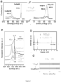
- FIG 4b shows the Cu Ls-edge soft X-ray absorption spectra (sXAS) of the catalyst and corresponding reference standard materials.
- the results show that the V-Cu 2 S exhibits Cu 2 S features before reaction and both Cu 0 and Cu + features after reaction (derived Cu 2 S/Cu-V).
- EDX Energy dispersive X-ray spectroscopy
- Positron annihilation spectroscopy which probes the type and relative concentration of defect vacancies, was carried out to investigate the copper surface.
- the positron lifetime spectra ( Figure 4e ) and the lifetime parameters (see Table 3) show that both the CSVE catalyst and also the Cu 2 S bulk control, exhibit three lifetimes.
- the study assigns the shortest lifetime T 1 (around 260 ps) to the bulk and the longest component ( ⁇ 3 , > 2 ns) to the annihilation of orthopositronium atoms formed in the large voids present in the material.
- the study ascribes the component ⁇ 2 (circa 380 ps) to positron annihilation in trapped Cu vacancies.
- the electrochemical CO 2 reduction activity and selectivity was first characterized using a three-electrode H-cell system.
- the catalysts were loaded onto a glassy carbon electrode. Linear sweep voltammetry curves were obtained in a CO 2 -saturated 0.1 M KHCO 3 aqueous solution ( Figure 5a ).
- the CSVE catalyst exhibits a total geometric current density of ⁇ 32 mA cm -2 at -0.95 V versus a reversible hydrogen electrode (RHE) during 16 h of continuous electrocatalysis ( Figure 5b ).
- Electrocatalysis was performed using cathodic potentials in the range of -0.85 V to -1.15 V versus RHE ( Figure 5c ). As the applied potential becomes more negative (-0.9 V versus RHE), multi-carbon products are observed, indicating that C-C coupling occurs beyond this potential (see below table 4)
- the study measured the electrochemically active surface area (ECSA) of each catalyst. While the Cu 2 S/Cu-V nanoparticles had a slightly larger ECSA than the Cu 2 S and Cu control nanoparticles, the ECSA difference between the CSVE and control catalysts is less than 4%. The shift in the C2 production pathway and the high current density towards alcohols is therefore ascribed to the catalyst itself rather than to any substantive increase in electrochemically active surface area.
- ECSA electrochemically active surface area
- reaction 2 It was then sought to engineer the reaction environment to work in tandem with the CSVE catalyst to suppress ethylene and boost multi-carbon alcohol production.
- concentration of OH - will be increased proximate to the catalyst surface affecting the bound O* intermediate along the ethylene pathway (Reaction 2), but is expected to leave the ethanol pathway largely unaffected.
- the study turned to a flow-cell configuration that allowed operating in alkaline KOH electrolyte without compromising CO 2 availability.
- the study chose highly alkaline KOH as the electrolyte to increase the pH and electrolyte conductivity, and further enhance CO 2 reduction reaction kinetics by suppressing hydrogen evolution.
- the configuration bypasses the low CO 2 solubility in KOH via the diffusion of CO 2 across a gas-liquid interface adjacent to the catalyst surface ( Figure 2a ).
- the catalyst was first deposited by spray-coating a nanoparticle ink onto a carbon gas-diffusion electrode (see details below).
- Linear sweep voltammetry curves ( Figure 6b ) of the three catalysts show the lower overpotentials of the CSVE-Cu catalyst at fixed current densities highlighting the improved activity.
- the partial current density exceeded 120 mA cm -2 for multi-carbon alcohols.
Description
- The technical field generally relates to catalytic methods for CO2 reduction, and more particularly to electrocatalysts having a core-shell structure and associated methods for electrochemical CO2 reduction.
- The efficient electrochemical conversion of carbon dioxide (CO2) into valuable carbon-based fuels and compounds is desirable and a technology that enhances such a conversion can, for example, enable the storage of intermittent renewable electricity as well as net reductions of greenhouse gas emissions. Existing catalyst systems for such CO2 reduction processes have a number of drawbacks, including low selectivity for producing certain compounds.
- Shaodong Sun et al. in Diversified copper sulfide (Cu2-xS) micro-/nanostructures: a comprehensive review on synthesis, modifications and applications (Nanoscale, vol. 9, No. 32, 1 January 2017, pages 11357-11404) describes Cu2-xS micro-/nanostructures comprising core-shell structures with a metal core (such as Au core or CuO core) and one or more Cu2S shells The diversified Cu2-xS micro-/nanostructures apply in the fields of photocatalyst, energy conversion, in vitro biosensor and in vivo imaging and therapy.
- There is a need for improved techniques and catalyst systems for efficient electrochemical CO2 reduction and related methods and systems of producing chemical compounds.
- A unique catalyst system for electrocatalyzing conversion of CO2 into multi-carbon alcohols or other hydrocarbons is disclosed herein. In some implementations, the catalyst system can have a core-shell structure, with a core that includes metal sulphide (preferably copper sulphide) material, and a shell enveloping the core and comprising a metal (preferably copper) material with vacancies. The catalyst system can include nanoparticles having the core-shell structure and can be made in situ by deploying a catalyst precursor that is made of vacancy enriched metal sulphide particles having an external layer that is reduceable in situ to form reduced metallic shells with enriched vacancies surrounding the corresponding metal sulphide cores. One advantageous feature of the catalyst systems is a notably enhanced selectivity to multi-carbon alcohol production from CO2. A number of systems, methods, catalyst systems, and various implementations and optional features thereof, are disclosed herein.
- According to a first aspect, the invention provides a catalyst system for electrocatalyzing conversion of CO2 into multi-carbon hydrocarbons and/or alcohols, remarkable in that it comprises a core-shell structure comprising a core that is composed of a metal sulphide and a shell having a lower sulphur content than the core and that is composed of a metal with vacancies; in that the metal of the core and the metal of the shell are the same metal; and in that the shell has a thickness that is ranging between 1 nm to 3 nm as determined by EDS line scan measurement, wherein EDS line scan is carried out using a JEM-ARM 200F Atomic Resolution Analytical Microscope operating at an accelerating voltage of 200 kV.
- Surprisingly, it has been found by the inventors that a catalyst system comprising core-shell particles wherein the core comprises sulphur atoms and the shell comprises intentional vacancies is able to block the reaction pathway for ethylene. Thus, the catalyst system of the invention allows the ratio of alcohol-to-ethylene to be increased by over 6 times compared to relative bare-copper nanoparticles, highlighting a new approach to electro- chemically produce alcohols instead of alkenes. In addition, C2+ alcohol production rate of 126 mA cm-2 was achieved with a selectivity of 32% Faradaic efficiency (FE). This represents a 1.6 times enhancement over the highest previously-reported current density for multi-carbon alcohols. Steering CO2 reduction post-C-C coupling across such a wide range of production rates demonstrates the robustness of the invention and brings alcohol production into a more commercially relevant regime.
- In a preferred embodiment, the core-shell structure is core-shell particles. The definition of the catalyst system reads: a catalyst system for electrocatalyzing conversion of CO2 into multi-carbon hydrocarbons and/or alcohols, comprising core-shell particles comprising a core that is composed of a metal sulphide and a shell that is composed of a metal with vacancies.
- With preference, one or more of the following features may be used with preference to further define the core-shell particles:
- The core-shell particles are core-shell nanoparticles, with preference the nanoparticles have a spherical shape.
- The core-shell particles are core-shell nanoparticles and the nanoparticles have an average diameter ranging between 1 nm and 30 nm as determined by transmission electron microscopy (TEM), preferably between 2 nm and 20 nm, more preferably between 3 nm and 15 nm, even more preferably between 4 nm and 12 nm, and most preferably between 5 and 10 nm.
- In a variant of the invention, the core-shell structure is a layered material. The definition of the catalyst system reads: a catalyst system for electrocatalyzing conversion of CO2 into multi-carbon hydrocarbons, comprising: an outer layer comprising a metal material with vacancies and being exposable to CO2, and an inner material covered by the outer layer and comprising a catalytic metal and a secondary non-metal compound; with preference, the inner material is a metal sulphide.
- With preference:
- the outer layer comprises or consists of copper with vacancies, and the inner material comprises or consists of copper sulphide; and/or
- the secondary non-metal compound comprises or consists of sulphur; and/or
- the core-shell structure is a core-shell layered material comprising an inner layer forming a core and an outer layer forming a shell.
- Thus, the definition of the catalyst may read: a catalyst system for electrocatalyzing conversion of CO2 into multi-carbon hydrocarbons and/or alcohols, comprising a core-shell layered material comprising an inner layer forming a core that is composed of a metal sulphide, and an outer layer forming a shell that is composed of a metal with vacancies.
- Preferably, the layered material has a thickness ranging between 1 nm and 30 nm, preferably between 2 nm and 20 nm, more preferably between 3 nm and 15 nm, even more preferably between 4 nm and 12 nm, and most preferably between 5 and 10 nm. The thickness of the layered material is determined by EDS line scan measurement wherein the EDS line scan is carried out using a JEM-ARM 200F Atomic Resolution Analytical Microscope operating at an accelerating voltage of 200 kV.
- Whatever the definition of the catalyst system used and whatever its structure, one or more of the following features may be used with preference to further define the catalyst system:
- The metal of the core and the metal of the shell are the same metal.
- The metal of the core and the metal of the shell are copper.
- The metal sulphide of the core is copper sulphide and the metal of the shell is copper.
- The catalyst system comprises copper and sulphur and copper and sulphur are distributed evenly throughout the core.
- The catalyst system comprises copper and sulphur and copper and sulphur are present in a non-stoichiometric ratio.
- The core of the core-shell particles comprises or consists of a djurleite phase.
- The core of the core-shell particles has a covellite structure.
- The core and shell have an overall Cu/S molar ratio ranging between 3 and 7, preferably between 4 and 6, and more preferably between 4.5 and 5.5, as determined by XRF-1800 quantitative analysis with a 4 kW Thin-window X-ray Tube.
- The shell is formed by subjecting a vacancy enriched copper sulphide particle to reduction, thereby releasing sulphur from an external layer of the particle and forming the shell depleted in sulphur while retaining the sulphur in the core.
- The shell has a thickness that is ranging between 1.5 nm to 2.5 nm, and preferably between 1.75 nm to 2.25 nm, through EDS line scan measurement, wherein EDS line scan is carried out using a JEM-ARM 200F Atomic Resolution Analytical Microscope operating at an accelerating voltage of 200 kV.
- The core-shell particle causes modulation in branching in favour of ethanol relative to ethylene.
- The shell is substantially depleted in sulphur.
- The shell has a thickness that is smaller than a diameter of the core; with preference, the shell has a thickness that is between 2 to 4 times smaller than a diameter of the core, preferably between 2.5 to 3.5 times smaller than a diameter of the core, or 3 times smaller than a diameter of the core.
- The multi-carbon alcohols comprise ethanol and/or propanol.
- According to a second aspect, the invention relates to a method for electrochemical production of a multi-carbon alcohol, comprising the steps of:
- contacting CO2 gas and an electrolyte with an electrode comprising the catalyst system as defined in the first aspect, such that the CO2 contacts a catalyst layer comprising the catalyst system;
- applying a voltage to provide a current density to cause the CO2 gas contacting the catalyst layer to be electrochemically converted into the multi-carbon alcohol; and
- recovering the multi-carbon alcohol.
- With preference, one or more of the following features may be used with preference to further define the method for electrochemical production of a multi-carbon alcohol:
- The current density provided in the current collection structure is predetermined for selective electrochemical conversion of the CO2 into a target multi-carbon alcohol.
- The recovered multi-carbon alcohol comprises ethanol and/or propanol.
- The electrolyte comprises an alkaline potassium compound; with preference, the electrolyte comprises KOH.
- The voltage applied is ranging from 300 to 700 mV, preferably from 400 to 600 mV, and more preferably from 450 to 550 mV, at potentials of -0.95 V vs RHE.
- The method is operated to provide at least 6 times improvement in partial current density for the multi-carbon alcohol compared with those of Cu2S nanoparticles without vacancy under the same operating conditions.
- The method is operated to provide at least 19 times improvement in partial current density for the multi-carbon alcohol compared with those of pure Cu nanoparticles under the same operating conditions.
- The method is operated to provide at least 46 times improvement in partial current density for the multi-carbon alcohol compared with those of bulk Cu2S under the same operating conditions.
- The method is operated to provide at least 44 times improvement in partial current density for the multi-carbon alcohol compared with those of bulk Cu under the same operating conditions.
- The catalyst system increases the energy barrier in the ethylene pathway.
- In a preferred embodiment, the method further comprises a step of deploying a catalyst system precursor comprising copper sulphide particles in the electrolyte and applying the voltage to:
- initiate the electrochemical production of the multi-carbon alcohol; and
- subject an external layer of the copper sulphide particles to reduction to remove sulphur therefrom and thereby form the shell of the catalyst system.
- According to a third aspect, the invention provides the use of the catalyst system as defined in the first aspect in the electrochemical production of at least one multi-carbon alcohol.
- With preference, one or more of the following features may be used with preference to further define the use of the catalyst system:
- The use is performed in a process according to the second aspect.
- The electrochemical production of the multi-carbon alcohol is performed in an alkaline electrolyte; with preference, the alkaline electrolyte comprises KOH.
- The at least one multi-carbon alcohol comprises ethanol and/or propanol.
- According to a fourth aspect, the invention provides the use of the catalyst system as defined in the first aspect in the electrochemical production of at least one multi-carbon hydrocarbon; with preference, the at least one multi-carbon hydrocarbon comprises ethylene.
- According to a fifth aspect, the invention provides a method of manufacturing a catalyst system comprising core-shell particles for electrocatalyzing conversion of CO2 into multi-carbon hydrocarbons and/or alcohols, the method comprising the following steps:
- preparing particles that comprise vacancy enriched metal sulphide;
- subjecting the particles to reduction to produce a reduced metallic shell with enriched vacancies surrounding a metal sulphide core, thereby forming the core-shell particle;
- wherein, the catalyst system is according to the first aspect of the invention.
- With preference, one or more of the following features may be used with preference to further define the method of manufacturing the catalyst system of the invention:
- The particles that are prepared are nanoparticles; with preference, the nanoparticles are colloidal nanoparticles.
- The nanoparticles that are prepared are composed of copper sulphide.
- The particles are prepared using a solvothermal method.
- The reduction of the particles comprises electroreduction by contacting the particles with CO2 saturated electrolyte and applying a voltage to provide a current density to cause CO2 gas contacting the particles to be electrochemically converted into the multi-carbon hydrocarbon; with preference, the electrolyte comprises an alkaline KOH electrolyte.
- The electroreduction is performed in a two-compartment electrochemical H-cell with a proton exchange membrane as a separator and a flow-cell configuration comprising a gas-diffusion layer with an anion exchange membrane.
- The electroreduction is conducted for at least 1 minute, at least 2 minutes, at least 3 minutes, at least 4 minutes, at least 5 minutes, or between 1 and 6 minutes or between 2 and 5 minutes, to form the core-shell particles.
- The electroreduction is performed in an electroreduction unit that is subsequently used to produce the multi-carbon hydrocarbons such that the core-shell particles are formed in situ.
- In an embodiment, the method further comprises a step of washing the collected particles and then drying the washed particles. With preference, the washing is performed with acetone and hexane, and the drying is performed under vacuum conditions.
- In a preferred embodiment, the step of preparing of the particles comprises the following sub-steps:
- dissolving Cu(acac)2 in a solvent to form a reaction mixture;
- heating the reaction mixture to form the particles;
- collecting the particles from the reaction mixture.
- With preference, one or more of the following features is true:
- the heating is performed at a temperature ranging from 230 to 250°C for 15 to 25 minutes; and/or
- the reaction mixture is subjected to mixing during the heating step; and/or
- the collecting comprises a centrifugation step.
- According to a sixth aspect, the invention provides the use of the catalyst system as defined according to the first aspect of the invention in a fuel cell.
- According to a seventh aspect, the invention provides a catalyst precursor for deployment in an electrocatalysis unit for in situ formation of a catalyst system for conversion of CO2 into multi-carbon alcohols, the catalyst precursor comprising vacancy enriched metal sulphide nanoparticles having an external layer that is reduceable in situ to form reduced metallic shells with enriched vacancies surrounding corresponding metal sulphide cores, wherein the metal is copper, wherein the vacancy enriched metal sulphide nanoparticles have a covellite structure and have an overall Cu/S molar ratio ranging between 1 and 3 by XRF-1800 quantitative analysis with a 4 kW Thin-window X-ray Tube; wherein the vacancy enriched metal sulphide nanoparticles have a generally spherical shape and an average diameter ranging between 3 nm and 30 nm as determined by transmission electron microscopy (TEM).
- With preference, one or more of the following features may be used with preference to further define the catalyst precursor of the invention:
- The vacancy enriched metal sulphide nanoparticles are formed by dissolving Cu(acac)2 in a solvent to form a reaction mixture, heating the reaction mixture to form the nanoparticles; collecting the nanoparticles from the reaction mixture.
- The vacancy enriched metal sulphide nanoparticles have an average diameter ranging between 3 nm and 20 nm as determined by transmission electron microscopy (TEM), preferably between 3 nm and 15 nm, even more preferably between 4 nm and 12 nm, and most preferably between 5 nm and 10 nm.
- The vacancy enriched metal sulphide nanoparticles comprise a djurleite phase.
- The metal and sulphur are distributed evenly throughout the vacancy enriched metal sulphide nanoparticles.
- The multi-carbon alcohols comprise ethanol and/or propanol.
- According to an eighth aspect, the invention provides the use of the catalyst precursor as defined in the seventh aspect, in an electrocatalysis operation for conversion of CO2 into multi-carbon alcohols; preferably the multi-carbon alcohols comprise ethanol and/or propanol.
- According to a ninth aspect, the invention provides a system for CO2 electroreduction to produce multi-carbon hydrocarbons, comprising:
- an electrolytic cell configured to receive a liquid electrolyte and CO2 gas;
- an anode; and
- a cathode comprising a catalyst system as defined in the first aspect of the invention or comprising a catalyst precursor as defined in the seventh aspect of the invention.
- With preference, the electrolytic cell is configured to be operable at conditions that maximize production of multi-carbon alcohols.
- According to a tenth aspect, the invention provides a method for electrochemical production of a multi-carbon hydrocarbon, comprising:
- contacting CO2 gas and an electrolyte with an electrode comprising the catalyst system as defined in the first aspect of the invention, such that the CO2 contacts a catalyst layer comprising the catalyst system;
- applying a voltage to provide a current density to cause the CO2 gas contacting the catalyst layer to be electrochemically converted into the multi-carbon hydrocarbon; and
- recovering the multi-carbon hydrocarbon;
- The invention also provides a method for electrochemical production of a multi-carbon hydrocarbon, comprising:
- contacting CO2 gas and an electrolyte with an electrode comprising the catalyst system as defined in the first aspect of the invention, such that the CO2 contacts a catalyst layer comprising the catalyst system;
- applying a voltage to provide a current density to cause the CO2 gas contacting the catalyst layer to be electrochemically converted into the multi-carbon hydrocarbon; and
- recovering the multi-carbon hydrocarbon;
- the method further comprises providing a negative potential to promote selective electrochemical conversion of the CO2 into a target multi-carbon alcohol; wherein the negative potential is ranging from -1 to 0.9 V vs RHE, preferably ranging from -0.99 to -0.91 V vs RHE, more preferably ranging from -0.98 to -0.92 V vs RHE, even more preferably ranging from - 0.97 to -0.93 V vs RHE, most preferably ranging from -0.96 to -0.94 V vs RHE, and even most preferably is -0.95 V vs RHE.
- With preference, the negative potential that is applied is pre-determined in accordance with selective production of a target multi-carbon hydrocarbon.
-
-
Figure 1 illustrates reaction Gibbs free energy diagrams. (a) Atomic models. Reaction Gibbs free energy diagram from the adsorbed C2H3O intermediate to ethylene (black lines) and ethanol (red lines) for (b) pristine copper (Cu), (c) Cu with Cu vacancy, and (d) Cu with Cu vacancy and subsurface sulphur (S) slab models. (e-g) The same reaction free energy after applying -0.5 V bias potential. -
Figure 2 (a-c) TEM, HRTEM and HAADF-STEM images of synthesized V-Cu2S nanoparticles. (d) XRD pattern of obtained nanostructures. Lower grey lines are standard JCPDS data of monoclinic CU1.94S [23-0959], revealing the synthesized copper sulphide has copper deficiencies. -
Figure 3 Catalyst design and structural characterization. (a) Schematic illustration of Cu2S/Cu-V core/shell vacancy engineering (CSVE) electrocatalyst design for multi-carbon alcohols production from CO2 reduction. (b-c) TEM and EDS mapping of the original V-Cu2S nanoparticles, showing the uniform size and the homogeneous distribution of Cu and S. (d-g) EDS mapping, HRTEM, and EDS line scan of the reduced CSVE nanocatalysts after electrochemical reduction, showing the removal of sulphur from the nanoparticle surface. V-Cu means Cu with surface vacancies. -
Figure 4 represents the characterizations of the CSVE catalyst, (a) XPS of the original V-Cu2S nanoparticles and XPS sputter depth profiling of the derived CSVE catalyst (Cu2S/Cu-V). (b) Cu L3-edge XAS spectra of the original V-Cu2S nanoparticles, the derived CSVE catalyst, a reference Cu2S standard and a reference Cu standard. (c) EDX, showing the change of elements between V-Cu2S and CSVE catalyst. (d) The atomic ratio of copper and sulphur in the V-Cu2S and CSVE catalyst, calculated by XRF. (e) Positron lifetime spectra and (f-g) Schematic representations of trapped positrons of copper vacancies. -
Figure 5 illustrates the CO2 electrochemical reduction performance in an H-cell system. (a) Linear sweep voltammetry curves in a CO2-saturated 0.1 M KHCO3 aqueous solution for the CVSE and control catalysts. (b) Chrono-amperometry results at a potential of -0.95 V vs RHE. (c) Faradaic efficiencies (FE) of alkenes and alcohols on CSVE nanocatalyst at different applied potentials. (d) Faradic efficiency of alcohols (ethanol and propanol) and ethylene on different catalysts at the potential of -0.95 V vs RHE. Inside circles show the corresponding faradic efficiency ratio of alcohols to alkenes. -
Figure 6 . CO2 electrochemical reduction performance in a flow-cell system. (a) Schematic illustration of the cathode flow-cell system using a gas-diffusion electrode for CO2. (b) Linear sweep voltammetry curves in the 1M KOH electrolyte for the CVSE and control catalysts. (c) Faradaic efficiencies (FE) of C2+ alcohols (ethanol and propanol) on CSVE nanocatalyst in the current density range of 200 - 600 mA cm-2. (d) Plot of C2+ alcohol partial current density versus maximum C2+ alcohol Faradaic efficiency for catalysts in a flow-cell system, references (10, 11). -
Figure 7 . (a) The potential versus the corresponding applied total current density using CSVE catalyst for CO2 reduction in 1M KOH electrolyte in Flow-cell system. (b) Faradaic efficiency of products distribution in 1M KOH electrolyte at different applied total current densities. (c) Faradic efficiency over reaction time for ethanol and propanol in 1M KOH electrolyte at an applied total current density of 400 mA cm-2 and a potential of -0.92 V vs RHE. (d) Faradaic efficiencies of ethanol, propanol, and ethylene with different KOH concentration at an applied total current density of 400 mA cm-2 and a potential of -0.92 V vs RHE. -
Figure 8 . Faradaic efficiencies of ethanol, propanol, and ethylene on different catalysts measured in 1M KOH electrolyte at an applied potential of -0.92 V vs RHE in the flow-cell system. -
Figure 9 . The plot of C2+ alcohol partial current density versus maximum C2+ alcohol Faradaic efficiency for catalysts in H-cell system, references (1-9). -
- Table 1. Comparison of CO2 reduction to ethylene and ethanol using different copper-based catalysts running at different potentials in H-cell.
- Table 2. Activation energy barrier (eV) at equilibrium potential (U°) and at applied bias (-0.5 V) for the first hydrogenation step on different surfaces.
- Table 3. Positron lifetime parameters of V-Cu2S derived CSVE nanoparticles and Cu2S bulk.
- Table 4. Faradaic efficiency of carbon products at the different applied potentials using designed CSVE nanocatalyst.
- Table 5. Comparison of CO2 reduction to ethylene, ethanol and n-propanol using different copper-based catalysts running at -0.95 V vs RHE in H-cell.
- Table 6. Faradaic efficiency of products distribution in 1M KOH electrolyte at different applied total current densities using the CSVE nanocatalyst in flow-cell system.
- Table 7. Comparison of CO2 reduction to multi-carbon alcohols and n-propanol (C3H7OH) using copper-based catalysts. For catalysts 1-9 the values measured are data in the H-cell and for catalysts 10-11 the values measured are data in the flow-cell.
- Techniques described herein relate to enhanced catalyst systems that can be used for electrochemical CO2 reduction and the production of multi-carbon compounds. Electrochemical reduction of CO2 into value-added carbon-based products addresses the need for long-term storage of renewable electricity. Liquid multi-carbon alcohols, such as ethanol and n-propanol, are highly desired as renewable transportation fuels. They offer high energy densities, ease of long-range transport, and direct usage.
- The electrochemical production of ethanol and n-propanol is complicated by a reaction pathway that involves multiple CO2 molecules and fully 12 electron transfer steps. The pathway's selectivity to alcohols suffers from competition from the electroreduction to the gas-phase C2 product ethylene. Creating catalysts that manage these numerous reaction steps for selective production of liquid multi-carbon alcohols has remained an unsolved challenge. Conventional catalysts have largely targeted C2 vs. C1 production; whereas the present invention targets productivity following the C-C coupling reaction step. In this way, the present invention aims to enhance hydrogenation of C2+ intermediates toward alcohols.
- As will be explained in further detail below, the invention explored positive factors to switch CO2 reduction reaction pathways from ethylene to alcohol production. Using a sequential synthesis in which colloidal nucleation was combined with electrochemical reduction, the invention engineered a new catalyst that efficiently electrochemically reduces CO2 to n-propanol and ethanol.
- The invention provides a catalyst system for electrocatalyzing conversion of CO2 into multi-carbon hydrocarbons and/or multi-carbon alcohols, comprising a core-shell structure comprising a core that is composed of a metal sulphide and a shell that is composed of a metal with vacancies.
- The multi-carbon hydrocarbons are, or preferably comprise ethylene. The multi-carbon alcohols are, or comprise, ethanol and/or propanol.
- In some implementations, the catalyst system can include a core comprising a catalytic metal (e.g., copper) and a modifier (e.g., sulphur atoms), and a shell enveloping the core and comprising a catalytic metal (e.g., copper) with intentional vacancies. This synthesis strategy can be applied to other metals, such as lead, zinc, tin, et. al. However, Cu is the most promising metal for multi-carbon products over CO2 reduction thanks to its moderate CO binding energy. In this invention, we focus therefore on the Cu-based catalysts, especially on the Cu metal shell because of its surface catalytic active sites. The core-bound sulphur atoms, particularly in combination with the surface Cu vacancy, increase the energy barrier of post C-C coupling towards ethylene production while leaving the ethanol pathway generally unaffected, compared to that of the pure Cu catalyst. The designed Cu2S/Cu-V core/shell-vacancy catalyst provides a shift selectivity for alcohols. Advantageously, the core-shell particle of the invention causes modulation in branching in favour of ethanol relative to ethylene.
- It is noted that Cu2O was also tested as the core, and it was found that Cu2O core suffers from being reduced to pure Cu over the course of CO2 reduction. Thus, the sulphur-based catalyst systems as disclosed herein provide advantageous functionalities over oxygen-based systems.
- The metal of the core and the metal of the shell are the same metal; with preference, the metal of the core and the metal of the shell are copper. Thus, in a preferred embodiment of the invention, the metal sulphide of the core is copper sulphide and the metal of the shell is copper.
- As it is understood, the shell has a lower sulphur content than the core. In a preferred embodiment, the shell is substantially depleted in sulphur.
- In a preferred embodiment, the catalyst comprises copper and sulphur and copper and sulphur are distributed evenly throughout the core.
- To achieve the Cu2S/Cu-V core/shell-vacancy structure, the V-Cu2S nanoparticles with non-stoichiometric Cu is first synthesized, and then the nanoparticle to produce the Cu2S/Cu-V structure is partially reduced.
- In the engineered structure, the surface metal is the active species over the electrocatalysis. The designed metal sulphide core affects the electronic properties of the surface metal and thereby the post C-C coupling intermediates and the following reaction pathway toward the production of multi-carbon alcohols over CO2 reduction.
- In a preferred embodiment, copper and sulphur are present in a non-stoichiometric ratio
- The Cu2S/Cu-V core/shell vacancy catalyst is produced through partially reducing the V-Cu2S nanoparticles. The Cu and S of the V-Cu2S nanoparticles present in a non-stoichiometric ratio. After the initial electroreduction, the surface is reduced to the metallic Cu with vacancy while the core changed to stoichiometric Cu2S.
- The designed metal sulphide core and the surface vacancy synergistically affect the electronic properties of the surface metal and thereby the post C-C coupling intermediates and the following reaction pathway toward the production of multi-carbon alcohols over CO2 reduction.
- In a preferred embodiment, the core comprises, or consists of, a djurleite phase. As it is known to the person skilled in the art, for compositions near Cu2S a number of phases exist at room temperature. These may be divided into two broad categories based on the nature of the sulphur close-packing in the structure. The first category comprises chalcocite and djurleite with structures based on hexagonal close-packing of sulphur atoms. The second category comprises digenite-like structures and anilite with sulphur atoms in approximately cubic close-packing. The structure of the core as a djurleite phase can be determined by transmission electron microscopy.
- In a preferred embodiment, the core has a covellite structure. The initial V-Cu2S has a djurleite phase; while the core of the final Cu2S/Cu-V core/shell vacancy catalyst has a chalcocite phase.
- In a preferred embodiment, the core and shell have an overall Cu/S molar ratio ranging between 3 and 7 as determined by XRF-1800 quantitative analysis with a 4 kW Thin-window X-ray Tube, preferably between 4 and 6, and more preferably between 4.5 and 5.5.
- Furthermore, examples of the shell-core catalyst systems described herein can include other elements besides sulphur and copper, such as oxygen and tin.
- The catalyst system of the invention can have a variety of properties and features. For example, the catalyst system can take the form of a catalytic material that includes core-shell particles, with copper sulphide core and copper-with-vacancies shell. Other structures are also possible, such as a material that includes an outer copper-with-vacancies layer and an inner copper sulphide material, and thus does not necessarily have a particle structure that is the same as the shell-core particles. In addition, the catalyst system can have certain physical properties, such as the size of the core and shell, and the compositions of the core and shell.
- According to some implementations disclosed herein, a catalyst system for the electroreduction of CO2 into alcohols can have a core/shell structure designed to provide and leverage certain vacancy properties to the catalyst system. For example, the catalyst system can include a nanoparticle core comprising sulphur atoms and a shell comprising intentional copper vacancies, to block the reaction pathway for ethylene. This innovative core/shell-vacancy engineering (CSVE) strategy for the catalyst system generally increases the reaction barrier to ethylene without affecting the path for alcohols.
- Referring to
Figure 3a , the catalyst system (which can also be referred to as the electrocatalyst, as inFigure 3a ) includes a Cu2S core and a Cu-V shell for enhanced electrocatalytic conversion of CO2 into liquid alcohols. - In a preferred embodiment, the catalyst system is in the form of core-shell particles. Advantageously, the core-shell particles are nanoparticles, with preference the nanoparticles have a spherical shape.
- Advantageously, the nanoparticles have an average diameter ranging from 1 nm to 30 nm as determined by transmission electron microscopy (TEM), preferably from 2 nm to 20 nm, more preferably from 3 nm to 15 nm, even more preferably from 4 nm to 12 nm, and most preferably from 5 to 10 nm.
- Thus, the shell has a thickness that is smaller than the diameter of the core. With preference, the shell has a thickness that is between 2 to 4 times smaller than a diameter of the core, preferably 2.5 to 3.5 times smaller than a diameter of the core, or 3 times smaller than a diameter of the core.
- In an embodiment, the catalyst system comprises colloidal nanoparticles dispersed in a medium of suspension, such as in methanol.
- In an embodiment, the core-shell structure is a core-shell layered material comprising an inner layer forming a core and an outer layer forming a shell.
- Preferably, the layered material has a thickness ranging between 1 nm and 30 nm, preferably between 2 nm and 20 nm as determined by EDS line scan measurement, wherein EDS line scan is carried out using a JEM-ARM 200F Atomic Resolution Analytical Microscope operating at an accelerating voltage of 200 kV, more preferably between 3 nm and 15 nm, even more preferably between 4 nm and 12 nm, and most preferably between 5 and 10 nm
- Whatever is the structure selected, the shell has a thickness ranging from 1 nm to 3 nm as determined by EDS line scan measurement, wherein EDS line scan is carried out using a JEM-ARM 200F Atomic Resolution Analytical Microscope operating at an accelerating voltage of 200 kV, preferably from 1.5 nm to 2.5 nm, and more preferably from 1.75 nm to 2.25 nm.
- Examples of the shell-core catalyst system described herein can be used as a catalyst layer in a composite multilayered electrocatalyst (CME) that includes a polymer-based gas-diffusion layer, a current collection structure, and the catalyst layer sandwiched in between.
- The current collection structure can include a carbon nanoparticle layer applied against the catalyst layer, and a graphite layer applied against the nanoparticle layer. In one possible implementation of the CME, it includes a hydrophobic polymer-based support such as polytetrafluoroethylene (PTFE); a shell-core catalyst system material deposited on top; a layer of carbon-based nanoparticles (NPs) atop the catalyst; and an ensuing layer of graphite as the electron conductive layer. In this configuration, the PTFE layer, which can substantially be pure PTFE or similar polymer, acts as a more stable hydrophobic gas-diffusion layer that prevents flooding from the catholyte; carbon NPs and graphite stabilize the metal catalyst surface; the graphite layer serves both as an overall support and current collector. In an alternative implementation, the CME includes a hydrophobic polymer-based layer; the shell-core catalyst material deposited on top; and then a layer of conductive material such as graphite deposited on top of the catalyst layer.
- In this configuration, the stabilization material (e.g., carbon nanoparticles) is not present as a distinct layer in between the graphite and the catalyst layers. Other features of the CME and related CO2RR methods as described in
Nature Catalyst 2018, 1, 421-428 - Therefore, the invention encompasses a system for CO2 electroreduction to produce multi-carbon hydrocarbons, comprising:
- an electrolytic cell configured to receive a liquid electrolyte and CO2 gas;
- an anode; and
- a cathode comprising a catalyst system as defined above or comprising a catalyst precursor as defined below.
- With preference, the electrolytic cell is configured to be operable at conditions that maximize production of multi-carbon alcohols.
- The invention also relates to the use of the catalyst system according to the invention in a fuel cell.
- As it will be described in detail below, the shell is preferably formed by subjecting a vacancy enriched copper sulphide particle to reduction, thereby releasing sulphur from an external layer of the particle and forming the shell depleted in sulphur while retaining the sulphur in the core.
- The invention also contemplates a method of manufacturing a catalyst system comprising core-shell particles for electrocatalyzing conversion of CO2 into multi-carbon hydrocarbons and/or alcohols, the method comprising the following steps:
- preparing particles that comprise vacancy enriched metal sulphide;
- subjecting the particles to reduction to produce a reduced metallic shell with enriched vacancies surrounding a metal sulphide core, thereby forming the core-shell particle.
- In a preferred embodiment, the catalyst system is as described above.
- With preference, the particles that are prepared are nanoparticles; with preference, the nanoparticles are colloidal nanoparticles.
- In a preferred embodiment, the prepared nanoparticles are composed of copper sulphide.
- Preferably, the particles are prepared using a solvothermal method.
- In an embodiment, the step of preparing the particles comprises the following sub-steps:
- dissolving Cu(acac)2 in a solvent to form a reaction mixture;
- heating the reaction mixture to form the particles;
- collecting the particles from the reaction mixture.
- Cu(acac)2 is Copper(II) acetylacetonate (CAS Number 13395-16-9) and is commercially available at Merck. The solvent is selected from thiols; for example, the solvent is dodecanethiol The use of thiols is advantageous as thiols can serve as the solvent and the sulphur source.
- The heating is performed at a temperature ranging from 230 to 250°C for a duration lasting from 15 to 25 minutes. The reaction mixture is subjected to mixing during the heating step, with preference under the protection of an inert gas such as nitrogen gas or argon. The resulting nanoparticles are collected by centrifugation. Preferably, the step of preparing the particles comprises a sub-step of washing the collected particles and then drying the washed particles. For instance, the washing is performed with acetone and hexane, and the drying is performed under vacuum conditions.
- In a preferred embodiment, the reduction of the particles comprises electroreduction by contacting the particles with CO2 saturated electrolyte and applying a voltage to provide a current density to cause CO2 gas contacting the particles to be electrochemically converted into the multi-carbon hydrocarbon. With preference, the electrolyte comprises an alkaline KOH electrolyte.
- Preferably, the electroreduction is performed in a two-compartment electrochemical H-cell with a proton exchange membrane as a separator and a flow-cell configuration comprising a gas-diffusion layer with an anion exchange membrane.
- To form the core-shell particles, the electroreduction is preferably conducted for at least 1 minute, more preferably for at least 2 minutes, even more preferably for at least 3 minutes, most preferably for at least 4 minutes, even most preferably for at least 5 minutes.
- In an embodiment, to form the core-shell particles, the electroreduction is preferably conducted for a time ranging from 1 min to 6 minutes, preferably ranging from 2 to 5 minutes.
- The catalyst system can also be made by preparing a catalyst precursor material or particles that are made of vacancy enriched metal sulphide material having an external layer that is reduceable in situ to form reduced metallic external layers with enriched vacancies coating or surrounding corresponding metal sulphide material. Thus, by subjecting the catalyst precursors to electroreduction, the core-shell catalyst system can be formed in situ.
- Thus, in an embodiment, the electroreduction is performed in an electroreduction unit that is subsequently used to produce the multi-carbon hydrocarbons such that the core-shell particles are formed in situ.
- The invention also provides a catalyst precursor for deployment in an electrocatalysis unit for in situ formation of a catalyst system for conversion of CO2 into multi-carbon hydrocarbons, the catalyst precursor comprising vacancy enriched metal sulphide nanoparticles having an external layer that is reduceable in situ to form reduced metallic shells with enriched vacancies surrounding the corresponding metal sulphide cores. The multi-carbon hydrocarbons comprise multi-carbon alcohols, such as ethanol and/or propanol.
- In an embodiment, the vacancy enriched metal sulphide nanoparticles are formed by dissolving Cu(acac)2 in a solvent to form a reaction mixture, heating the reaction mixture to form the nanoparticles; collecting the nanoparticles from the reaction mixture.
- The vacancy enriched metal sulphide nanoparticles have an average diameter ranging from 3 nm to 30 nm as determined by transmission electron microscopy (TEM), preferably from 3 nm to 20 nm, more preferably from 3 nm to 15 nm, even more preferably from 4 nm to 12 nm, and most preferably from 5 to 10 nm.
- The vacancy enriched metal sulphide nanoparticles have a generally spherical shape. They comprise have a covellite structure and preferably a djurleite phase.
- The vacancy enriched metal sulphide nanoparticles have an overall Cu/S molar ratio ranging between 1 and 3 as determined by XRF-1800 quantitative analysis with a 4 kW Thin-window X-ray Tube. Indeed, the vacancy enriched metal sulphide is the initial nanoparticle without electroreduction. The molar ratio of Cu/S is therefore between 1 and 3. After reduction, the surface V-Cu2S is reduced to metallic Cu, the ratio of Cu/S increases therefore between 3 and 7.
- According to the invention, the metal is a catalytic metal, preferably the metal is copper.
- The metal and sulphur atoms are advantageously distributed evenly throughout the vacancy enriched metal sulphide nanoparticles.
- The invention also encompasses the use of the catalyst precursor as defined above, in an electrocatalysis operation for conversion of CO2 into multi-carbon hydrocarbons; with preference, the into multi-carbon hydrocarbons comprise multi-carbon alcohols.
- The catalyst system is particularly useful in the electrocatalytic conversion of CO2 into multi-carbon alcohols, as is explained and evidenced in detail. Indeed, the invention focused on enhanced alcohols production using the catalyst system described herein and provides advantageous conditions for such a production. Indeed, the catalyst system of the invention increases the energy barrier in the ethylene pathway.
- For example, good selectivity for multi-carbon alcohols was found at potentials of about -0.95V vs RHE. However, when a more negative potential than -0.95V vs RHE was applied, for example, at -1.1V vs RHE, the faradic efficiency of ethylene was found to increased to 42%, while that of alcohols decreased to 3.6%. Thus, it should be noted that the core-shell catalyst systems described herein can also be used for producing other types of hydrocarbon products (e.g., ethylene) under certain corresponding electroreduction conditions.
- Therefore, the invention contemplates a method for electrochemical production of a multi-carbon alcohol, comprising the steps of:
- contacting CO2 gas and an electrolyte with an electrode comprising the catalyst system as defined above, such that the CO2 contacts a catalyst layer comprising the catalyst system;
- applying a voltage to provide a current density to cause the CO2 gas contacting the catalyst layer to be electrochemically converted into the multi-carbon alcohol; and
- recovering the multi-carbon alcohol; preferably the recovered multi-carbon alcohol comprises ethanol and/or propanol.
- In accordance with the invention, the current density provided in the current collection structure is predetermined for selective electrochemical conversion of the CO2 into a target multi-carbon alcohol.
- In an embodiment, the electrolyte comprises an alkaline potassium compound; with preference, the electrolyte comprises KOH. Other electrolytes are also considered, such as KHCO3.
- In a preferred embodiment, the method comprises a step of deploying a catalyst system precursor comprising copper sulphide particles in the electrolyte and applying the voltage to:
- initiate the electrochemical production of the multi-carbon alcohol; and
- subject an external layer of the copper sulphide particles to reduction to remove sulphur therefrom and thereby form the shell of the catalyst system.
- Preferably the voltage applied is ranging from 300 to 700 mV, more preferably from 400 to 600 mV, and even more preferably from 450 to 550 mV, at potentials of -0.95 V vs RHE.
- The method of the invention may be operated to provide at least 6 times improvement in partial current density for the multi-carbon alcohol compared with those of Cu2S nanoparticles without vacancy under the same operating conditions. In the engineered structure, the surface Cu vacancy and the Cu2S core synergistically affect the electronic properties of the active sites and thereby the post C-C coupling intermediates and the following reaction pathway toward the production of multi-carbon alcohols over CO2 reduction. The production rate of multi-carbon alcohols is, therefore, higher than those of Cu2S and pure Cu catalysts.
- The method of the invention may be operated to provide at least 19 times, improvement in partial current density for the multi-carbon alcohol compared with those of pure Cu nanoparticles under the same operating conditions.
- The method of the invention may be operated to provide at least 46 times improvement in partial current density for the multi-carbon alcohol compared with those of bulk Cu2S under the same operating conditions. Furthermore, the nanoparticles have higher activity compared to the bulk controls and thus leading to higher partial current density.
- The method of the invention may be operated to provide at least 44 times improvement in partial current density for the multi-carbon alcohol compared with those of bulk Cu under the same operating conditions.
- The invention also contemplates a method for electrochemical production of a multi-carbon hydrocarbon, comprising:
- contacting CO2 gas and an electrolyte with an electrode comprising the catalyst system as defined above, such that the CO2 contacts a catalyst layer comprising the catalyst system;
- applying a voltage to provide a current density to cause the CO2 gas contacting the catalyst layer to be electrochemically converted into the multi-carbon hydrocarbon; and
- recovering the multi-carbon hydrocarbon.
- In an embodiment, the method comprises providing a negative potential to promote selective electrochemical conversion of the CO2 into a target multi-carbon alcohol; with preference, the negative potential is ranging from -1 to 0.9 V vs RHE, preferably ranging from -0.99 to -0.91 V vs RHE, more preferably ranging from -0.98 to -0.92 V vs RHE, even more preferably ranging from -0.97 to -0.93 V vs RHE, most preferably ranging from -0.96 to -0.94 V vs RHE, and even most preferably is-0.95 V vs RHE.
- In another embodiment, the method comprises providing a negative potential to promote electrochemical conversion of the CO2 into a target multi-carbon hydrocarbon; with preference, the target multi-carbon hydrocarbon is ethylene; and/or the negative potential is - 1.1V vs RHE.
- Computational Details. The projected augmented wave (PAW) approach and the generalized gradient approximation (GGA) of Perdew, Burke and Ernzerhof (PBE) with DFT-D3 method for the van der Waals correction employed in the Vienna ab initio Simulation Package (VASP) were used to perform all the plane wave density functional theory (DFT) computations.
- Electrochemical measurements. Electrocatalytic measurements were carried out in a three-electrode system at an electrochemical station (AUT50517). All potentials were measured against an Ag/AgCI reference electrode (3M KCI, BASi) and converted to the reversible hydrogen electrode (RHE) reference scale using:

- CO2 reduction electrolysis and product analysis. The electrolysis was performed in a two-compartment electrochemical H-cell with a proton exchange membrane (Nafion 117) as the separator and a flow-cell configuration consisting of a gas diffusion layer with an anion exchange membrane.
- Sample characterizations as well as the electrochemical measurements and computational simulation details are provided in the supplementary description provided below.
- Computational Details. Models of a pristine copper slab, a copper slab with a single atomic vacancy, and a Cu2S/Cu core/shell model with an atomic vacancy model are approximated by slab models (3×3×4 for Cu and Cu with Cu vacancy, and 3×3×6 for Cu with Cu vacancy and subsurface S slab) in a vacuum with the adsorbates binding to the active sites of the surface. Dipole corrections and spin polarizations are implemented. DFT-D3 method with Becke-Jonson damping is performed for the van der Waals correction. To resemble the real bulk material and the surface, the two top layers are free to move due to interaction with the adsorbates, while the other layers are fixed in their optimized crystalline positions. T A cut-off energy of 450 eV for the plane wave basis sets and a 2 × 2 × 1 Γ-centered Monkhorst-Pack mesh for the k-points sampling in the first Brillouin zone, with a first order Methfessel-Paxton smearing parameter σ of 0.1 eV ensured that the energy convergence criteria is better than 1 meV for a vacuum of 20 Å or greater. The self-consistent field (SCF) convergence criterion is set to 1 × 10⁻⁴ eV for electronic iteration and the ionic relaxation continued until the maximum force was less than 0.02 eV/Å that was updated by the conjugate gradient approach. To calculate the thermodynamic properties, gas phase molecules are approximated by an ideal gas, while the adsorbates are treated using the quasi-harmonic approximation. All vibrational calculations are performed using the Atomic Simulation Environment (ASE) code. All barrier calculations were performed using the climbing image nudged elastic band method (Cl-NEB) with 4 images.
- Computational Model. This study investigates the CO2 reduction to ethanol and ethylene (shown with * in the following equations). Three different models are considered:
- 1) Pristine copper (Cu) as the control model.
- 2) Cu with Cu vacancy as the control model (Cu-V).
- 3) Cu with Cu vacancy and subsurface sulphur (S) as the designed catalyst (Cu2S/Cu-V).
- The core/shell model is demonstrated in
Fig. 3 . All surfaces are fully relaxed before exposing them to the reaction intermediates. In each model and in each step of the simulations, the study examined different configurations for the adsorbed species and the most stable ones with the lowest energy are chosen to calculate the reaction energy diagram. Surfaces with vacancy in interaction with adsorbates, in few occasions, are subject to reconstruction. These configurations are avoided in the study's calculations. The calculated vacancy formation energy for Cu2S/Cu-V is 2.051 eV which is higher than that of the defected pure copper, Cu-V, with 1.3 eV vacancy formation energy. - Reaction Free Energy Calculations. According to Koper et al., reaction pathways for ethanol and ethylene from CO2 reduction are considered similar until the C2H3O intermediate. Thereafter, the reaction pathway for ethylene and ethanol splits as mentioned in the following:
- Pathway A (Ethylene pathway):
- A1:
∗ C 2 H 3 O + (H + + e- ) → ∗ 0 + C2H4
- A2:
∗O + (H + + e- ) → ∗ OH
- A3:
*OH + (H + + e- ) → ∗ + H 2 O
- A1:
- Pathway B (Ethanol pathway):
- B1:
∗ C2H3O + (H + + e- ) → ∗ C 2 H 4 O
- B2:
∗ C2H4O +(H + + e- ) → ∗ C 2 H 5 O
- B3:
∗ C 2 H 5 O + (H + + e- ) → ∗ + C 2 H 5 OH
- B1:
- To find the free energy diagram of each process the study calculated the reaction free energy (ΔGrxn ). The details of this calculation for the pathways A and B are explained here:


- In these equations, the Computational Hydrogen Electrode (CHE) is used and, thus, the proton-coupled electron pair is replaced by the hydrogen gas. The Gibbs free energy at room temperature (T=298.15 K) and ambient pressure (Pgage = 0 Pa), by definition, is:

- In general, for heterogeneous catalysis, the last three terms in the Gibbs free energy for a solid surface do not change appreciably in the presence and absence of the adsorbates and are cancelled out in the above equations. However, the gas molecules show considerably different vibrational properties - and consequently ZPE, heat capacity and entropy - when free or adsorbed. Therefore, these terms are calculated for the adsorbates but for the solid catalyst the calculated DFT energy is sufficient.
- For ethylene, the main energy barrier after the adsorbed CH2CHO intermediate is the last protonation step to reduce adsorbed OH to water (~ 0.4 eV). For ethanol, the first protonation step of the CH2CHO intermediate, which reduces it to CH3CHO, is the main obstacle (~ 0.2 eV) after the branch. However, both ethylene and ethanol reaction pathways proceed downhill after the application of 0.5 eV to overcome the earlier dimerization energy barrier.
- Table 1 demonstrates the Gibbs free energies of the reactants and the possible products in their molecular gaseous states.
Table 1 Cu2S Cu -0.9 V vs RHE C2H4: 29% C2H4: 34% C2H5OH: 6% C2H5OH: 3% -1.0 V vs RHE C2H4: 45% C2H4: 50% C2H5OH: 4% C2H5OH: 2% - For each surface, the potential determining step (PDS) which determines the required overpotential to make all the reaction steps downhill is mentioned in table 2.
Table 2 Cu (U0 = -0.373 V) Cu with vacancy (U0 = -0.305) Core/shell-vacancy (U0 = 0.191) U = 0V U = - 0.5V U = 0V U = - 0.5V U = 0V U = - 0.5V Ethylene Pathway 0.672 0.422 0.500 0.251 1.277 1.027 Ethanol Pathway 0.720 0.470 0.684 0.434 0.602 0.352 - Activation Energy Barrier Calculations. The computational hydrogen electrode (CHE) that is used to calculate the free energy diagram under different applied potentials, captures energetic differences between elementary steps in proton-coupled-electron-transfer (PCET) processes. In this model, the chemical potential of the proton-electron pair (H+ + e-) is considered to be equivalent to the chemical potential of a hydrogen molecule (H2) at the reference reversible hydrogen electrode (RHE) potential. However, DFT models cannot determine the chemical potential of a sole proton (H+) in a bulk electrolyte. Therefore, similar to previous studies on copper, we determined the activation energy barrier for an equivalent hydrogenation reaction. Hence, the proton-coupled-electron system was considered to be reduced to a surface adsorbed proton via the following equation in:

- The potential under which this reaction is in equilibrium (the Gibbs free energy equal to zero) is considered as the equilibrium potential (U°). Therefore, the activation energy barrier (Eact ) calculated via DFT can be extrapolated to the other potentials by the following equation:

Fig. 4 and mentioned in Table 4. - Bader Charge Analysis and Electron Density of States. Due to the proposed vacancy defect in the catalyst, the copper-copper bond length is enlarged. Therefore, oxygen (an intermediate in ethylene pathway) prefers the bridge site with a two O-Cu coordination number as the adsorption site, while in pristine copper the hollow site with a four O-Cu coordination number is more preferable. The calculated electrostatic charge density by Bader charge analysis also shows weaker bonding between the adsorbed oxygen and the surface copper in a core/shell-vacancy system as compared to a pristine copper surface with strong four-fold bonding. This weak bonding might be the main reason ethylene production is less favourable on the core/shell-vacancy catalyst. On the other hand, the strong bonding on pristine copper could be the main reason that the OH desorption step in the largest barrier (after the CH3CHO branch) in ethylene production.
- XPS core level binding energy (CLBE) shift calculation. The study simulated the XPS CLBE shift (ECLBEs ) for the Cu2S/Cu core/shell model and the Cu2S/Cu-V core/shell vacancy model using VASP code. The relative CLBE shift between two systems is defined as:

- Extended x-ray absorption fine-structure (EXAFS) simulation. The study used IFEFFIT, an ab initio software to calculate phase and amplitudes. These ab initio phases and amplitudes were used in the EXAFS equation:

- The neighbouring atoms to the central atom(s) are divided into j shells, with all atoms with the same atomic number and distance from the central atom grouped into a single shell. Nj denotes the number of neighbouring atoms in shell j at a distance of Rj from the central atom. feff
i (π, k, Rj) is the ab initio amplitude function for shell j. The Debye-Waller term

- Transfer process of the hydrophobic nanocrystals to an aqueous solution. In a typical transfer process, 200 µL 3-mercaptopropionic (MPA) was added into 15 mL of chloroform with 10 mg sample. The turbid solution was stirred for 3 h, followed by centrifugation. The precipitate was washed with acetone and further dried in a vacuum chamber.
- Characterization. X-ray diffraction patterns (XRD) were measured on a Philips X'Pert Pro Super X-ray diffractometer equipped with graphite-monochromatized Cu Kα radiation. X-ray photoelectron spectroscopy (XPS) was carried out with the Thermo Scientific K-Alpha XPS system. An Al Kα source with a 400µm spot size was used for measurements to detect photo-electrons at specific energy ranges to determine the presence of specific elements. Sputter depth profiling was performed with an ion gun at 1keV in order to avoid spurious features (e.g. ion beam damage), at a rate of approximately 1 nm/s, where each step has a duration of 20 s. Transmission electron microscopy (TEM) and high-resolution transmission electron microscopy (HRTEM) observations, which were performed on Hitachi H-7650 and JEOL-2010F with an acceleration voltage of 200 kV. High-angle annular dark field scanning transmission electron microscopy (HAADF- STEM) and Energy dispersive X-ray spectroscopy (EDS) were carried out using a JEM-ARM 200F Atomic Resolution Analytical Microscope operating at an accelerating voltage of 200 kV. Elemental mappings and line scans were collected by a Gatan GIF Quantum 965 instrument. Elemental ratio analysis for the samples was measured by an XRF-1800.
- Electrochemical active surface area (ECSA) measurement. To determine the ECSA of the electrodes, the study uses two methods to estimate the ECSA. In the first method, cyclic voltammetry (CV) using the ferri-/ferrocyanide redox couple ([Fe(CN)6]3-/4-) was employed. The CV was carried out in a nitrogen-purged 5 mM K3Fe(CN)6/0.1M KCI solution with Ag/AgCI (3M, KCI) and platinum gauze as the reference electrode and counter electrode, respectively. ECSA can be calculated according to the Randles-Sevcik equation at room temperature:

- In the second, the study uses a double layer capacitances method to measure the surface roughness factors for the samples relative to polycrystalline Cu foil. ECSA = R f × S, where S stands for the real surface area of the smooth metal electrode, which was generally equal to the geometric area of glassy carbon electrode (in this work, S =0.19 cm2). The roughness factor R f was estimated from the ratio of double-layer capacitance C for the working electrode and the corresponding Cu foil electrode, that is, R f = C / CCu foil. The C was determined by measuring the geometric current density at a potential at which no Faradaic process was occurring against the scan rate of cyclic voltammetry (CV). CV was performed in the same electrochemical cell as in the bulk electrolyses with a Nafion proton exchange membrane and 0.1 M KHCO3 electrolyte. The liner slope gives the C.
- IR correction. The study used potentiostatic electrochemical impedance spectroscopy (PElS) to determine uncompensated resistance (Ru). The resistance values were 80 Ohms for Cu2S-V, 78 Ohms for Cu2S, and 75 Ohms for Cu in H-cell, and 6.0 Ohms for Cu2S-V, 5.5 Ohms for Cu2S, and 5.0 Ohms for Cu in Flow-cell configurations respectively. At all potentials tested, the potential was manually corrected using Ohm's law:

- CO2 reduction product analysis. Gas-phase and liquid-phase products were quantified by gas chromatography (GC) and nuclear magnetic resonance (NMR) spectroscopy, respectively.
- The GC, running Argon (Linde, 99.999%) as a carrier gas, contained a Molecular Sieve 5A capillary column and a packed Carboxen-1000 column which were used together to separate hydrogen, methane, ethylene and CO2. A thermal conductivity detector (TCD) was used to quantify hydrogen (H2) and carbon monoxide (CO) and a flame ionization detector (FID) was used to quantify methane (CH4) and ethylene (C2H4).
- The liquid products were quantified using Nuclear magnetic resonance spectroscopy (NMR). 1H NMR spectra of freshly acquired samples were collected on
Agilent DD2 500 spectrometer in 10% D2O using water suppression mode, with Dimethyl sulfoxide (DMSO) as an internal standard. Sixteen second relaxation time between the pulses was used to allow for complete proton relaxation. The faradic efficiency (FE) of the liquid products was calculated from the total amount of charge Q (in units of coulombs) passed through the sample and the total amount of the liquid products produced n (in moles). Q = I × t, where I (in amperes) is the reduction current at a specific applied potential and t is the time (in seconds) for the constant reduction current. - The faradic efficiency of the liquid products can be calculated as follows as examples:


- Ex-situ X-ray absorption (XAS) measurement. The ex-situ X-ray absorption measurements at the copper L3-edge were performed at the spherical grating monochromator (SGM) beamline 11ID-1 at the Canadian Light Source. The scanning energy range of the Cu Ls-edge was between 920 and 960 eV.
- Positron Annihilation Measurement. Sandwiched samples composed of catalyst, 22Na source and catalyst with a total count of 2 million were used for the positron lifetime experiments. A fast-slow coincidence ORTEC system with a time resolution of 270 ps full width at half-maximum was utilized. The ATSUP method was used for calculating positron lifetime. The electron density and the positron crystalline Coulomb potential were built via the non-self-consistent superposition of free atom electron density and Coulomb potential in the absence of the positron.
- Nanoparticles average diameter: The morphologies of the nanoparticles are observed by Transmission Electron Microscopy (TEM) images and the diameters are calculated by Image J software.
- The advantages of the present invention are illustrated by the following examples. However, it is understood that the invention is not limited to these specific examples.
- The present invention evaluated catalyst systems and structures and found that steering post-C-C coupling selectivity can enable high-efficiency electroreduction of carbon dioxide to multi-carbon alcohols.
- Engineering new copper-based catalysts that favour high-value alcohols is desired in view of the energy density, ready transport, and established use of these liquid fuels. In the design of catalysts, much progress has been made to target deliberately the C-C coupling step; while comparatively little effort has been expended to target post-C-C coupling reaction intermediates. This study showed a new class of core/shell vacancy engineering (CSVE) catalysts that utilize sulphur atoms in the nanoparticle core and intentional copper vacancies in the shell to achieve efficient electrochemical CO2 reduction to propanol and ethanol; the catalyst did so by shifting selectivity away from the competing ethylene reaction. The study increased the ratio of alcohol-to-ethylene by over 6 times compared to bare-copper nanoparticles, highlighting a new approach to electro-produce alcohols instead of alkenes. The study achieved a C2+ alcohol production rate of 126 mA cm-2 with a selectivity of 32 ± 1% Faradaic efficiency (FE).
- The renewable-energy-powered electrocatalytic reduction of carbon dioxide (CO2) to value-added carbon-based products offers to contribute crucial energy storage to the effort to address growing energy demand. Recent progress in electrocatalytically converting CO2 has resulted in the production of gaseous carbon products such as carbon monoxide (CO), methane (CH4), and ethylene (C2H4), and C1 liquids such as formate (HCOOH).
- The production of liquid multi-carbon alcohols is also highly desired: it stands to enable the synthesis of sustainable fuels that leverage high energy densities (23 KJ/L ethanol, 27 KJ/L propanol) for long-range transportation applications. Unfortunately, the production of multi-carbon alcohols via direct CO2 electroreduction remains below that required for economic viability due to the limited selectivity and low activity of present-day catalysts.
- Among electrocatalysts for CO2 reduction, Cu-based materials are the most prone to reduce CO2 to C2 and above products, with alkenes traditionally dominating multi-carbon product formation. To develop more efficient electrocatalysts for alcohol production, it is desirable to modify the catalyst structure to promote the desired alcohol and suppress alkene electrosynthesis. Additionally, it would be advantageous to understand the mechanisms that underlie selectivity to enable further catalyst refinement.
- In the present invention, it was reasoned that - since ethylene and ethanol share a penultimate reaction intermediate (*C2H3O) - one could potentially modify a catalyst's surface structure to target the hydrogenation of this intermediate, and thereby promote C2 liquid production. Suppressing oft-produced ethylene could enhance production and selectivity toward alcohols.
- Several ways have previously been employed to engineer Cu surfaces to tune the energetics of intermediate binding. Introducing metal atomic vacancy defects can influence electrocatalytic performance by adjusting the electronic structure of neighbouring atoms and consequently the energy barriers of the rate-limiting reaction intermediates. Copper sulphide structures may be of interest because they may be able to provide a means to form stable surface defects and control the density of surface vacancies. Additionally, copper sulphide derived catalysts can provide long-range modifications of the local density of surface states by introducing sulphur into the Cu structure and affect thereby CO binding.
- This obtained initial results revealing that varying Cu catalyst by introducing S could lead to a notable difference in the ratio of ethanol to ethylene produced (see Table 1). These data lead to examination in greater depth, using computational analysis, a key rate-limiting step along the CO2-to-C2 pathway. In computational studies, it was found that a modified Cu2S core with Cu surface could account for modulation in branching in favour of ethanol relative to ethylene.
- Specifically, DFT studies examine the energetics seen by the adsorbed CH2CHO intermediate that may influence alcohol vs ethylene electrosynthesis. These studies point to strategies to switch CO2 reduction reaction pathways from ethylene to alcohol.
- The studies further included a systematic study of S-enriched Cu and surface vacancies, synthesizing a Cu2S/Cu-V (V: vacancy) nanoparticle structure that enables the controllable introduction of vacancies on a copper surface shell with a copper sulphide core. This core/shell-vacancy engineering (CSVE) catalyst enabled modifying the C2 reaction pathway, shifting selectivity away from ethylene and toward multi-carbon alcohols.
- To investigate the influence of a modified Cu core/shell structure and surface Cu vacancies on the final ethylene and ethanol reaction steps, density functional theory (DFT) was used to characterize changes in energy barriers relative to the case of pristine Cu. CO2 reduction to multi-carbon products proceeds through the dimerization or protonation of adsorbed CO intermediates. It has been shown that CO electroreduction to ethanol shares a similar pathway with ethylene up until the last three proton-coupled electron transfer steps. At this late stage, the adsorbed CH2CHO intermediate (*C2H3O) may proceed to ethanol through further carbon protonation; or to ethylene by leaving an oxygen atom adsorbed on the surface.
- The effect of surface modifications on the thermodynamics of the adsorbed CH2CHO intermediate was studied, and in turn the selectivity for ethylene versus ethanol production. The inventors have created three model systems: a pristine copper slab, a copper slab with a single atomic vacancy, and a Cu2S/Cu core/shell model with an atomic vacancy (see
Figure 1a ). Then, the following proposed reaction mechanisms representative of ethylene and ethanol production were explored: - Ethylene Pathway:
*C2H3O + (H+ + e-) → *O + C2H4 (1)
*O + (H+ + e-) → *OH (2)
*OH + (H+ + e-) → * + H2O (3)
- Ethanol Pathway:
*C2H3O + (H+ + e-) → *C2H4O (4)
*C2H4O + (H+ + e-) → *C2H5O (5)
*C2H5O + (H+ + e-) → * + C2H5OH (6)
- The following discussion regarding energies are related to the steps starting from *CH2CHO mentioned in
reactions 1 to 6. This study found that on pristine copper (Figure 1b and Table 2), both ethylene and ethanol have a low thermodynamic energy barrier (~ 0 eV) with a kinetic energy barrier of 0.422 and 0.470 eV (at applied -0.5 V potential, the required potential to overcome the rate determining C-C coupling step). These are surmountable at room temperature. The introduction of a surface copper vacancy (Figure 1c and Table 2) slightly increases the energy barrier for ethylene production (0.025 eV), though it remains thermodynamically favored; while the vacancy has a negligible effect on the ethanol pathway. Thus, the activation energy barriers at applied potential of -0.5 V for both ethylene (0.251 eV) and ethanol (0.434 eV) can be surmounted at room temperature. - Interestingly, a vacancy present on a copper shell with a Cu2S core increases the energy barrier in the ethylene pathway (1.027 eV), while leaving the ethanol pathway mostly unaffected (0.352 eV) (
Figure 1d ). Thus, if one applies an overpotential of 0.5 V (i.e., the required overpotential to overcome the early C-C coupling energy barrier), the ethanol pathway remains exergonic, but the ethylene pathway becomes unfavourable (Figure 1e-g and Table 2) suggesting selective production in favour of ethanol is achievable. - These results suggest that subsurface sulphur atoms and copper vacancy defects shift the balance in favour of ethanol by suppressing ethylene production through this common pathway.
- In light of these DFT findings, it was sought to synthesize a surface-vacancy-enriched copper sulphide/copper core/shell catalyst. A colloidal vacancy enriched Cu2S (V-Cu2S) nanoparticles was first prepared. Cuprous sulphide nanoparticles synthesized using the solvothermal method enable controlled copper vacancies in the surface structure of the catalyst. Next, the V-Cu2S was reduced in a CO2 saturated electrolyte, yielding a reduced metallic copper shell with enriched vacancies surrounding a Cu2S core.
- V-Cu2S nanoparticle synthesis. Synthesis of the copper (I) sulphide nanocrystals with controlled copper vacancies was performed according to a previously reported method described in Zhuang et al., Chem. Commun., 2012, 48, 9762-9764 with slight modification. In a typical procedure, 130 mg Cu(acac)2 was dissolved by 30 mL dodecanethiol (DDT) in a three-neck flask with magnetic stirring under the protection of nitrogen gas and heated at 240 °C for 20 min. The resulting V-Cu2S nanoparticles (V: vacancy) were collected by centrifugation, washed with acetone and hexane three times, and dried within a vacuum chamber.
- Cu2S nanoparticles synthesis. The copper (I) sulphide nanoparticles without copper vacancies were prepared using a previously reported method (Wu et al., see below). 1.25 mmol of ammonium diethyldithiocarbamate was mixed with 10 mL of dodecanethiol and 17 mL of oleic acid in a three-neck flask. The solution was heated up to 110 °C under Argon (Ar) flow followed by a quick injection of a suspension composed of 1 mmol of copper(II) acetylacetonate and 3 mL of oleic acid. The solution was then quickly heated up to 180 °C and kept at that temperature for 20 min. The resulting Cu2S nanoparticles were collected by centrifugation, washed with acetone and hexane three times and further dried in a vacuum chamber.
- Cu nanoparticles synthesis. In a typical synthesis of metallic copper nanoparticles (see Guo, below), 1.2 mmol CuBr and 15 mL oleylamine (OLA) were mixed in a three-neck flask under stirring at 80 °C for 30 min, then 1 mmol trioctylphosphine (TOP) was added and reacted at 80 °C until obtaining a colourless solution. The mixed solution was heated to 260 °C quickly and kept for 1h. The resulting Cu nanoparticles were precipitated by centrifugation, purified with acetone and hexane three times and further dried in a vacuum chamber.
- Preparation of V-Cu2S-derived Cu2S/Cu-V (CSVE) core/shell nanoparticles. During CO2 reduction, V-Cu2S nanoparticles are transformed to Cu2S/Cu-V core/shell nanoparticles by surface Cu+ reduction. Such core/shell nanoparticles can be obtained after initial running (2-5 min).
- Working electrode preparation and CO2 reduction measurements. To prepare a catalyst-coated glassy carbon electrode in an H-cell, 10 mg of V-Cu2S nanoparticles are mixed with 40 µL of 5 wt% Nation solutions and dispersed in 1 mL of 3:7 vol/vol methanol/water mixed solvent. The solution is sonicated for at least 30 min to form a homogeneous ink. For Flow-cell, we deposited 10 mg of catalyst mixed with 40 ul of 5 wt% Nafion in 1 mL methanol on a carbon gas-diffusion layer using the air-brush. We combined the diffusion layer coated catalyst, anion exchange membrane, and nickel anode together using PTFE spacers such that a liquid electrolyte could be introduced into the chambers between the anode and membrane as well as the membrane and the cathode. Gaseous CO2 could then be passed behind the gas-diffusion layer and diffuse into the liquid electrolyte present at the catalyst.
- In H-cell, the electrolyte was 0.1 M KHCO3 saturated with CO2, which was delivered into the cathodic compartment at a rate of 20.00 standard cubic centimetres per minute (s.c.c.m.). In Flow-cell, the electrolytes (KOH solution of various concentrations, 20 mL) were circulated through the electrochemical cell using peristaltic pumps. The electrolyte flow was kept at 10 mL min-1. The CO2 (Linde, 99.99%) flow was kept constant at 50 mL min-1 using a mass flow controller.
- To investigate the core/shell structure and to query the extent of surface vacancies, the nanoparticles were analyzed before and after reduction. The morphology of the copper sulphide nanoparticles was characterized using transmission electron microscopy (TEM,
Figure 2a ), high-resolution TEM (HRTEM,Figure 2b ) and high-angle annular dark-field scanning TEM (HAADF-STEM,Figure 3b andFigure 2c ). The nanoparticles have a high degree of uniformity and an average size of 8.5 nm. Energy dispersive X-ray spectroscopy (EDS) mapping data (Figure 3c ) reveal that copper and sulphur are distributed evenly throughout the particle. Powder x-ray diffraction (PXRD) analysis (Figure 2d ) shows good agreement with the standard Cu1.94S djurleite phase, thus indicating a non-stoichiometric ratio between copper and sulphur. - The active nanocatalyst used for CO2 reduction is then produced from the electrochemical reduction of the V-Cu2S nanoparticles which removes sulphur from the surface, thereby constructing Cu2S/Cu-V, i.e. a Cu2S core with an ultrathin metallic copper shell containing copper vacancies. In these nanoparticles, elemental Cu enriches the nanostructure, while the sulphur signal is decreased but still present, indicating that a fraction of sulphur has been removed during CO2 reduction (
Figure 3e ). To examine the sulphur distribution in the derived structure in detail, we acquired an EDS line scan: it revealed that sulphur mainly concentrates in the core of the nanoparticle, confirming the picture of a Cu2S/Cu core/shell nanostructure (Figure 3 f-g ). - To explore the variation in nanoparticles structure during CO2 reduction, and gain insight into the electronic configuration, the study used X-ray photoelectron spectroscopy (XPS) to probe the chemical composition of the copper sulphide nanoparticles before and after the CO2 reduction reaction. As shown in
Figure 4a , the Cu peaks, which possess a weak asymmetric tail, agree with a covellite structure. Combining with XPS core level binding energy simulation results, the study found consistent support for the view that the CSVE catalyst possesses Cu defects. Results of XPS and XPS sputter depth profiling (Figure 4a , grey curve), taken together, show the S 2p spectra of the catalyst after reaction. These indicate that sulphur is present at the core of the nanoparticle.Figure 4b shows the Cu Ls-edge soft X-ray absorption spectra (sXAS) of the catalyst and corresponding reference standard materials. The results show that the V-Cu2S exhibits Cu2S features before reaction and both Cu0 and Cu+ features after reaction (derived Cu2S/Cu-V). By simulating the EXAFS fitting of Cu K-edge in reduced space, the study found that the Cu-Cu bond distance of the CSVE catalyst becomes larger compared to the case of pure copper. Energy dispersive X-ray spectroscopy (EDX) results show that the sulphur concentration decreased after CO2 reduction reaction for 16 hours (Figure 4c ). The atomic ratios of Cu : S in the catalyst before (Cu/S = 1.94 ± 0.01) and after (Cu/S = 4.81 ± 0.02) reaction were obtained using X-ray fluorescence (XRF,Figure 4d ). - Positron annihilation spectroscopy (PAS), which probes the type and relative concentration of defect vacancies, was carried out to investigate the copper surface. The positron lifetime spectra (
Figure 4e ) and the lifetime parameters (see Table 3) show that both the CSVE catalyst and also the Cu2S bulk control, exhibit three lifetimes. The study assigns the shortest lifetime T 1 (around 260 ps) to the bulk and the longest component (τ 3, > 2 ns) to the annihilation of orthopositronium atoms formed in the large voids present in the material. The study ascribes the component τ 2 (circa 380 ps) to positron annihilation in trapped Cu vacancies. The relative intensities (I) of these lifetimes reflect that copper vacancies and bulk character are predominant in the CSVE nanoparticles and bulk Cu2S, respectively. Simulated results inFigure 4f and 4g reveal the projection of the positron density distribution for the pure Cu2S bulk and the CSVE nanoparticle sample, indicating the high vacancy-associated concentration in the latter.Table 3 Sample τ1 (ps) τ2 (ps) τ3 (ns) I1(%) I2(%) I3 (%) V-Cu2S-derived nanoparticles 264.0 373.0 2.98 43.8 55.1 1.11 Cu2S Bulk 259.3 381.0 6.90 67.8 32.2 0.03 - To probe electrocatalytic properties, the electrochemical CO2 reduction activity and selectivity was first characterized using a three-electrode H-cell system. The catalysts were loaded onto a glassy carbon electrode. Linear sweep voltammetry curves were obtained in a CO2-saturated 0.1 M KHCO3 aqueous solution (
Figure 5a ). The CSVE catalyst exhibits a total geometric current density of ~32 mA cm-2 at -0.95 V versus a reversible hydrogen electrode (RHE) during 16 h of continuous electrocatalysis (Figure 5b ). - Electrocatalysis was performed using cathodic potentials in the range of -0.85 V to -1.15 V versus RHE (
Figure 5c ). As the applied potential becomes more negative (-0.9 V versus RHE), multi-carbon products are observed, indicating that C-C coupling occurs beyond this potential (see below table 4)Table 4 Potential (V vs RHE) Hydrogen (FE, %) Methane (FE, %) Carbon monoxid e (FE, %) Formate (FE, %) Ethylene (FE, %) Acetate (FE, %) Acetalde hyde (FE, %) Ethylene glycol (FE, %) Ethanol (FE, %) Allyl alcohol (FE, %) Propiona Idehyde (FE, %) Propanol (FE, %) Total (FE, %) -0.85 15.8±2 0 16.5±1 66.0±3 0 0 0 0 0 0 0 0 ~98.3 -0.90 16.8±2 0.4±0.1 10.5±1 61.0±2 4.0±0.5 0.5±0.1 0 0 2.5±0.2 0 0 1.7±0.1 ~96.9 -0.95 13.8±1 0.3±0.1 3.5±0.3 30.8±2 19.0±2 0.5±0.1 0.4±0.1 1.9±0.1 15.1±1.5 3.0±0.3 2.9±0.2 8.0±0.7 ~99.2 -1.00 18.5±2 0.3±0.1 1.5±0.1 29.0±1 28.1±1 0.5±0.1 0 1.3±0.1 12.0±1 1.6±0.1 0.2±0.1 4.8±0.4 ~97.8 -1.05 29.8±3 2.1±0.2 0.5±0.1 17.7±1 32.2±1 0.2±0.1 0 1.2±0.1 5.1±0.5 0.2±0.1 0 3.5±0.3 ~92.5 -1.10 35.5±3 2.4±0.2 0 17.0±1 42.3±2 0.2±0.1 0 0.6±0.1 2.4±0.2 0 0 1.2±0.1 ~101. 6 -1.15 41.8±4 1.8±0.1 0 4.2±0.2 31.0±1 0.3±0.1 0 0.7±0.1 4.0±0.4 0 0 1.3±0.1 ~85.1 - At potentials of -0.95 V vs RHE, 500 mV above the potential at which C-C coupling is first observed, the CSVE nanocatalyst shows peak alcohol production. Interestingly, propanol (C3H7OH) and ethanol (C2H5OH) follow a similar selectivity trend with changes to the applied potential, indicating that ethanol and propanol share common intermediates along their reaction pathways. This is consistent with the assumption made in the DFT part of the study, wherein the study used ethanol as a proxy for overall alcohol electrosynthesis. The maximum faradic efficiency for C3H7OH and C2H5OH reaches 8 ± 0.7 % and 15 ± 1 % with a partial current density of 2.5 ± 0.1 and 4.8 ± 0.1 mA cm-2 at -0.95 V versus RHE, respectively (
Figure 5d ). - These represent 6 times, 19 times, 46 times, and 44 times improvements in partial current density for C2+ alcohols compared with those of Cu2S NPs without vacancy, pure Cu NPs, bulk Cu2S and bulk Cu under the same operating conditions.
- Moreover, the alcohol-to-ethylene ratio is enhanced from 0.18 on the bare-Cu NPs to 1.2, a 6 times increase with the CVSE catalyst, while overall C2+ selectivity remains similar (Table 5). It indicates that faradaic current was shifted from producing ethylene to producing alcohols.
Table 5 Nano V-Cu2S Nano Cu2S Nano Cu Bulk Cu2S Bulk CuS Bulk Cu C2H4 (FE, %) 19.0 ±2 28.5 ± 1 33.6 ± 2 3.0 ± 0.2 1.9 ± 0.2 16.5 ± 0.5 C2H5OH (FE, %) 15.1 ± 1.5 5.8 ± 0.5 4.3 ± 0.4 2.5 ± 0.2 0.5 ± 0.1 3.3 ± 0.3 C3H7OH (FE, %) 8.0 ± 0.7 3.8 ± 0.3 1.9 ± 0.1 1.9 ± 0.1 0 0.7 ± 0.1 - To characterize the intrinsic catalytic activity, the study measured the electrochemically active surface area (ECSA) of each catalyst. While the Cu2S/Cu-V nanoparticles had a slightly larger ECSA than the Cu2S and Cu control nanoparticles, the ECSA difference between the CSVE and control catalysts is less than 4%. The shift in the C2 production pathway and the high current density towards alcohols is therefore ascribed to the catalyst itself rather than to any substantive increase in electrochemically active surface area.
- It was then sought to engineer the reaction environment to work in tandem with the CSVE catalyst to suppress ethylene and boost multi-carbon alcohol production. At a high pH, the concentration of OH- will be increased proximate to the catalyst surface affecting the bound O* intermediate along the ethylene pathway (Reaction 2), but is expected to leave the ethanol pathway largely unaffected. The study turned to a flow-cell configuration that allowed operating in alkaline KOH electrolyte without compromising CO2 availability. The study chose highly alkaline KOH as the electrolyte to increase the pH and electrolyte conductivity, and further enhance CO2 reduction reaction kinetics by suppressing hydrogen evolution. The configuration bypasses the low CO2 solubility in KOH via the diffusion of CO2 across a gas-liquid interface adjacent to the catalyst surface (
Figure 2a ). The catalyst was first deposited by spray-coating a nanoparticle ink onto a carbon gas-diffusion electrode (see details below). - Linear sweep voltammetry curves (
Figure 6b ) of the three catalysts show the lower overpotentials of the CSVE-Cu catalyst at fixed current densities highlighting the improved activity. - The study then evaluated the CO2 reduction reaction activity in the current density range 200 - 600 mA cm-2 in 1M KOH (
Figure 6c ,Figure 7 and Table 6), a range facilitated by the use of a flow cell and the alkaline electrolyte. For the CSVE-Cu catalyst, the study achieved a Faradaic efficiency of 31% for multi-carbon alcohols (C2H5OH 25 ± 1% and C3H7OH 7 ± 0.5%). The partial current density exceeded 120 mA cm-2 for multi-carbon alcohols.Table 6 Applied current density (mA cm Hydroge n (FE, %) Methane (FE, %) Carbon monoxid e (FE, %) Formate (FE, %) Ethylene (FE, %) Acetate (FE, %) Ethanol (FE, %) Propanol (FE, %) Total (FE, %) 200 25.2±2 1.2±0.1 15.8±1 22.2±2 6.3±0.5 6.6±0.5 10.8±1 3.2±0.2 ∼91.3 300 16.8±1 0.8±0.1 10.6±1 17.7±1 8.6±0.5 3.5±0.2 11.2±1 4.0±0.3 ∼73.2 400 12.6±1 1.1±0.1 5.5±0.5 15.4±1 21.2±2 3.0±0.2 24.7±2 6.9±0.5 ∼90.4 500 13.7±1 2.2±0.2 5.7±0.5 11.3±1 18.3±1 3.5±0.2 20.4±2 6.1±0.5 ∼81.2 600 16.8±1 0.7±0.1 7.0±0.5 12.2±1 16.1±1 3.0±0.2 14.4±1 5.1±0.5 ∼75.3 - The faradic efficiency and partial current density exceeded, by a factor of 2, those of control catalysts, including both Cu2S without vacancy, and also pure Cu (
Fig. 8 ). The C2+ alcohol partial current density versus maximum C2+ alcohol Faradaic efficiency for a range of catalysts reported in the literature is provided inFigure 6d ,Fig. 9 and Table 7.Table 7 Sample FE/alcohols (ethanol + propanol, %) J/alcohols (ethanol + propanol) (mA cm-2) Reference 1. Cu- Pt 25 0.146 Green Chem. 18, 3216, 2016 19 2. Polished Cu2O 16.3 5.7 ACS Catal. 5, 2814, 2015 20 3. Cu2O-derived 10.4 1.55 J. Am. Chem. Soc. 134, 7231, 2012 21 4. Cu nanocubes 7.8 0.2 Angew. Chem. Int. Ed. 55, 5789, 2016 22 5. Cu2O-derived 17.2 5.4 J. Phy. Chem. C 120, 20058, 2016 23 6. Cu nanocrystals 21.4 4.2 J. Phy. Chem. lett. 7, 20, 2016 24 7. CuZnx 33.5 9.4 ACS Cata. 6, 8239, 2016 25 8. Cu nanoparticles 19.9 4.1 PNAS 114, 10560, 2017 26 9. Cu(100) 21.9 0.8 PNAS 114, 5918, 2017 27 Cu in H-cell 6.2 0.4 This work Cu2S/Cu in H-cell 9.6 1.3 This work CSVE-Cu in H-cell 23.1 7.3 This work 10. Cu nanoparticles 21.9 65 J. Power Sources 301, 219, 2016 28 11. Cu-DAT wires 30.8 81.2 ACS Cata. 7, 3313, 2017 29 Cu in Flow-cell 8.5 34 This work Cu2S/Cu in Flow cell 13.7 54.8 This work CSVE-Cu in Flow-cell 31.6 126 This work - The prior works results indicated in this table are from the below articles:
- Yang, H.-P., Yue, Y.-N., Qin, S., Wang, H. & Lu, J.-X. Selective electrochemical reduction of CO2 to different alcohol products by an organically doped alloy catalyst. Green Chem. 18, 3216-3220 (2016).
- Ren, D. et al. Selective electrochemical reduction of carbon dioxide to ethylene and ethanol on copper (I) oxide catalysts. ACS Catal. 5, 2814-2821 (2015).
- Li, C.W. & Kanan, M.W. CO2 Reduction at Low Overpotential on Cu Electrodes Resulting from the Reduction of Thick Cu2O Films. J. Am. Chem. Soc. 134, 7231-7234 (2012).
- Loiudice, A. et al. Tailoring Copper Nanocrystals towards C2 Products in Electrochemical CO2 Reduction. Angew. Chem. Int. Ed. 55, 5789-5792 (2016).
- Handoko, A.D. et al. Mechanistic Insights into the Selective Electroreduction of Carbon Dioxide to Ethylene on Cu2O-Derived Copper Catalysts. J. Phy. Chem. C 120, 20058-20067 (2016).
- Ren, D., Wong, N.T., Handoko, A.D., Huang, Y. & Yeo, B.S. Mechanistic Insights into the Enhanced Activity and Stability of Agglomerated Cu Nanocrystals for the Electrochemical Reduction of Carbon Dioxide to n-Propanol. J. Phys. Chem. Lett. 7, 20-24 (2016).
- Ren, D., Ang, B.S.-H. & Yeo, B.S. Tuning the Selectivity of Carbon Dioxide Electroreduction toward Ethanol on Oxide-Derived CuxZn Catalysts. ACS Catal. 6, 8239-8247 (2016).
- Kim, D., Kley, C.S., Li, Y. & Yang, P. Copper nanoparticle ensembles for selective electroreduction of CO2 to C2-C3 products. PNAS 114, 10560-10565 (2017).
- Hahn, C. et al. Engineering Cu surfaces for the electrocatalytic conversion of CO2: Controlling selectivity toward oxygenates and hydrocarbons. PNAS 114, 5918-5923 (2017).
- Ma, S. et al. One-step electrosynthesis of ethylene and ethanol from CO2 in an alkaline electrolyzer. J. Power Sources 301, 219-228 (2016).
- Hoang, T.T.H., Ma, S., Gold, J.I., Kenis, P.J.A. & Gewirth, A.A. Nanoporous Copper Films by Additive-Controlled Electrodeposition: CO2 Reduction Catalysis. ACS Catal. 7, 3313-3321 (2017).
Claims (16)
- A catalyst system for electrocatalyzing conversion of CO2 into multi-carbon hydrocarbons and/or alcohols, characterised in that it comprises a core-shell structure comprising a core that is composed of a metal sulphide and a shell having a lower sulphur content than the core and that is composed of a metal with vacancies; in that the metal of the core and the metal of the shell are the same metal ; and in that the shell has a thickness that is ranging between 1 nm to 3 nm as determined by EDS line scan measurement, wherein EDS line scan is carried out using a JEM-ARM 200F Atomic Resolution Analytical Microscope operating at an accelerating voltage of 200 kV.
- The catalyst system of claim 1, characterised in that one or more of the following is true:- the metal of the core and the metal of the shell are copper; and/or- the catalyst system comprises copper and sulphur, and in that copper and sulphur are distributed evenly throughout the core and/or copper and sulphur are present in a non-stoichiometric ratio; and/or- the core of the core-shell particles comprises or consists of a djurleite phase; and/or- the core of the core-shell particles has a covellite structure; and/or- the core and shell have an overall Cu/S molar ratio ranging between 3 and 7 as determined by XRF-1800 quantitative analysis with a 4 kW Thin-window X-ray Tube, preferably ranging between 4.5 and 5.5.- the shell is substantially depleted in sulphur; and/or- the shell has a thickness that is ranging between 1.5 nm to 2.5 nm as determined by EDS line scan measurement, wherein EDS line scan is carried out using a JEM-ARM 200F Atomic Resolution Analytical Microscope operating at an accelerating voltage of 200 kV; and/or- the shell has a thickness that is smaller than a diameter of the core; with preference, the shell has a thickness that is between 2 to 4 times smaller than a diameter of the core.
- The catalyst system of claim 1 or 2, characterised in that the core-shell structure is core-shell particles, preferably core-shell nanoparticles, with preference:- the nanoparticles have a spherical shape; and/or- the nanoparticles have an average diameter ranging between 3 nm and 30 nm as determined by transmission electron microscopy (TEM), with preference ranging between 5 nm and 10 nm.
- The catalyst system of any one of claims 1 or 2, characterised in that the core-shell structure is core-shell layered material comprising an inner layer forming a core and an outer layer forming a shell.
- A method for electrochemical production of a multi-carbon alcohol, characterized in that the method comprises the steps of:- contacting CO2 gas and an electrolyte with an electrode comprising the catalyst system as defined in any one of claims 1 to 4, such that the CO2 contacts a catalyst layer comprising the catalyst system;- applying a voltage to provide a current density to cause the CO2 gas contacting the catalyst layer to be electrochemically converted into the multi-carbon alcohol; and- recovering the multi-carbon alcohol;with preference, the method further comprises a step of deploying a catalyst system precursor comprising copper sulphide particles in the electrolyte and applying the voltage to:- initiate the electrochemical production of the multi-carbon alcohol; and- subject an external layer of the copper sulphide particles to reduction to remove sulphur therefrom and thereby form the shell of the catalyst system.
- Use of the catalyst system as defined in any one of claims 1 to 4 in the electrochemical production of at least one multi-carbon alcohol or of at least one multi-carbon hydrocarbon; with preference the at least one multi-carbon hydrocarbon comprises ethylene.
- A method of manufacturing a catalyst system comprising core-shell particles for electrocatalyzing conversion of CO2 into multi-carbon hydrocarbons and/or alcohols, characterised in that the method comprises the following steps:- preparing particles that comprise vacancy enriched metal sulphide;- subjecting the particles to reduction to produce a reduced metallic shell with enriched vacancies surrounding a metal sulphide core, thereby forming the core-shell particle;and in that the catalyst system is according to any one of claims 1 to 4.with preference, the particles that are prepared are nanoparticles.
- Use of the catalyst system as defined in any one of claims 1 to 4 in a fuel cell.
- A catalyst precursor for deployment in an electrocatalysis unit for in situ formation of a catalyst system for conversion of CO2 into multi-carbon alcohols, the catalyst precursor comprising vacancy enriched metal sulphide nanoparticles having an external layer that is reduceable in situ to form reduced metallic shells with enriched vacancies surrounding corresponding metal sulphide cores, wherein the metal is copper, wherein the vacancy enriched metal sulphide nanoparticles have a covellite structure and have an overall Cu/S molar ratio ranging between 1 and 3 by XRF-1800 quantitative analysis with a 4 kW Thin-window X-ray Tube; wherein the vacancy enriched metal sulphide nanoparticles have a generally spherical shape and an average diameter ranging between 3 nm and 30 nm as determined by transmission electron microscopy (TEM).
- The catalyst precursor of claim 9, characterised in that the vacancy enriched metal sulphide nanoparticles are formed by dissolving Cu(acac)2 in a solvent to form a reaction mixture, heating the reaction mixture to form the nanoparticles; collecting the nanoparticles from the reaction mixture.
- The catalyst precursor of claim 9 or 10, characterised in that the vacancy enriched metal sulphide nanoparticles:- have an average diameter ranging between 5 nm and 10 nm as determined by transmission electron microscopy (TEM); and/or- comprise a djurleite phase.
- The catalyst precursor of claim 11, wherein the metal and sulphur are distributed evenly throughout the vacancy enriched metal sulphide nanoparticles.
- Use of the catalyst precursor as defined in any one of claims 9 to 12, in an electrocatalysis operation for conversion of CO2 into multi-carbon alcohols.
- A system for CO2 electroreduction to produce multi-carbon hydrocarbons, comprising:- an electrolytic cell configured to receive a liquid electrolyte and CO2 gas;- an anode; and- a cathode comprising a catalyst system as defined in any one of claims 1 to 4 or comprising a catalyst precursor of any one of claims 9 to 12;with preference, the electrolytic cell is configured to be operable at conditions to maximize production of multi-carbon alcohols.
- A method for electrochemical production of a multi-carbon hydrocarbon, comprising:- contacting CO2 gas and an electrolyte with an electrode comprising the catalyst system as defined in any one of claims 1 to 4, such that the CO2 contacts a catalyst layer comprising the catalyst system;- applying a voltage to provide a current density to cause the CO2 gas contacting the catalyst layer to be electrochemically converted into the multi-carbon hydrocarbon; and- recovering the multi-carbon hydrocarbon;further comprising providing a negative potential to promote electrochemical conversion of the CO2 into a target multi-carbon hydrocarbon; with preference, the target multi-carbon hydrocarbon is ethylene; and/or the negative potential is -1.1V vs RHE
- A method for electrochemical production of a multi-carbon hydrocarbon, comprising:- contacting CO2 gas and an electrolyte with an electrode comprising the catalyst system as defined in any one of claims 1 to 4, such that the CO2 contacts a catalyst layer comprising the catalyst system;- applying a voltage to provide a current density to cause the CO2 gas contacting the catalyst layer to be electrochemically converted into the multi-carbon hydrocarbon; and- recovering the multi-carbon hydrocarbon;further comprising providing a negative potential to promote selective electrochemical conversion of the CO2 into a target multi-carbon alcohol; wherein the negative potential is ranging from -1 to 0.9 V vs RHE, preferably from -0.96 to -0.94 V vs RHE.
Applications Claiming Priority (2)
| Application Number | Priority Date | Filing Date | Title |
|---|---|---|---|
| US201862670278P | 2018-05-11 | 2018-05-11 | |
| PCT/EP2019/061854 WO2019215247A1 (en) | 2018-05-11 | 2019-05-08 | Core/shell-vacancy engineering (csve) of catalysts for electrochemical co2 reduction |
Publications (2)
| Publication Number | Publication Date |
|---|---|
| EP3791010A1 EP3791010A1 (en) | 2021-03-17 |
| EP3791010B1 true EP3791010B1 (en) | 2023-03-29 |
Family
ID=66589514
Family Applications (1)
| Application Number | Title | Priority Date | Filing Date |
|---|---|---|---|
| EP19724761.2A Active EP3791010B1 (en) | 2018-05-11 | 2019-05-08 | Core/shell-vacancy engineering (csve) of catalysts for electrochemical co2 reduction |
Country Status (8)
| Country | Link |
|---|---|
| US (1) | US11268199B2 (en) |
| EP (1) | EP3791010B1 (en) |
| CA (1) | CA3095972C (en) |
| DK (1) | DK3791010T3 (en) |
| ES (1) | ES2944341T3 (en) |
| FI (1) | FI3791010T3 (en) |
| PT (1) | PT3791010T (en) |
| WO (1) | WO2019215247A1 (en) |
Families Citing this family (8)
| Publication number | Priority date | Publication date | Assignee | Title |
|---|---|---|---|---|
| EP4045699A1 (en) * | 2019-12-12 | 2022-08-24 | Iritaly Trading Company S.r.l. | Electrocatalytic method and apparatus for the simultaneous conversion of methane and coto methanol through an electrochemical reactor operating at ordinary temperatures and pressures, including ambient ones |
| CN112301368B (en) * | 2020-10-10 | 2022-11-04 | 华东理工大学 | Hydrophobic carbon-coated copper microsphere and preparation method and application thereof |
| CN113136599B (en) * | 2021-03-13 | 2022-09-16 | 复旦大学 | Catalytic CO 2 Method for producing ion vacancy of electrocatalyst for reduction |
| CN113718290B (en) * | 2021-09-07 | 2022-07-26 | 北京化工大学 | Cu-CuS/BM electrode material for preparing formate by electrocatalytic oxidation of glycerol and preparation method thereof |
| CN114277402B (en) * | 2021-12-15 | 2023-01-06 | 华南理工大学 | Conjugated conductive polymer modified copper-based catalyst and preparation method and application thereof |
| CN115318306B (en) * | 2022-02-22 | 2023-05-12 | 哈尔滨工业大学 | Cu-rich alloy 2 S-nanocrystal-modified Cu nanosheets and preparation method and application thereof |
| CN115044936B (en) * | 2022-04-28 | 2023-07-07 | 合肥工业大学 | Pb 4 S 3 Br 2 Nano heterojunction catalyst with@CdS core-shell structure, preparation method and application thereof |
| CN116237063B (en) * | 2023-02-17 | 2023-08-15 | 兰州大学 | Yttrium promoted carbon dioxide reduction catalyst and its preparation method |
Family Cites Families (2)
| Publication number | Priority date | Publication date | Assignee | Title |
|---|---|---|---|---|
| US9873115B2 (en) * | 2013-07-01 | 2018-01-23 | The Regents Of The University Of Colorado, A Body Corporate | Nanostructured photocatalysts and doped wide-bandgap semiconductors |
| CN107376851A (en) * | 2017-08-23 | 2017-11-24 | 三峡大学 | A kind of preparation method and applications of partial vulcanization metal organic frame composite |
-
2019
- 2019-05-08 PT PT197247612T patent/PT3791010T/en unknown
- 2019-05-08 EP EP19724761.2A patent/EP3791010B1/en active Active
- 2019-05-08 ES ES19724761T patent/ES2944341T3/en active Active
- 2019-05-08 CA CA3095972A patent/CA3095972C/en active Active
- 2019-05-08 DK DK19724761.2T patent/DK3791010T3/en active
- 2019-05-08 FI FIEP19724761.2T patent/FI3791010T3/en active
- 2019-05-08 US US17/052,075 patent/US11268199B2/en active Active
- 2019-05-08 WO PCT/EP2019/061854 patent/WO2019215247A1/en active Application Filing
Also Published As
| Publication number | Publication date |
|---|---|
| ES2944341T3 (en) | 2023-06-20 |
| DK3791010T3 (en) | 2023-06-06 |
| CA3095972C (en) | 2023-08-22 |
| CA3095972A1 (en) | 2019-11-14 |
| US11268199B2 (en) | 2022-03-08 |
| WO2019215247A1 (en) | 2019-11-14 |
| PT3791010T (en) | 2023-05-12 |
| FI3791010T3 (en) | 2023-06-09 |
| EP3791010A1 (en) | 2021-03-17 |
| US20210238759A1 (en) | 2021-08-05 |
Similar Documents
| Publication | Publication Date | Title |
|---|---|---|
| EP3791010B1 (en) | Core/shell-vacancy engineering (csve) of catalysts for electrochemical co2 reduction | |
| Pan et al. | Intermediate adsorption states switch to selectively catalyze electrochemical CO2 reduction | |
| Liang et al. | Unveiling in situ evolved In/In2O3− x heterostructure as the active phase of In2O3 toward efficient electroreduction of CO2 to formate | |
| Liu et al. | Quantum-dot-derived catalysts for CO2 reduction reaction | |
| Peng et al. | Separated growth of Bi-Cu bimetallic electrocatalysts on defective copper foam for highly converting CO2 to formate with alkaline anion-exchange membrane beyond KHCO3 electrolyte | |
| Zhang et al. | Atomic nickel cluster decorated defect-rich copper for enhanced C2 product selectivity in electrocatalytic CO2 reduction | |
| Sun et al. | Highly efficient overall urea electrolysis via single-atomically active centers on layered double hydroxide | |
| Yang et al. | Electrocatalytic CO2 reduction to alcohols by modulating the molecular geometry and Cu coordination in bicentric copper complexes | |
| Li et al. | Enhanced electroreduction of CO2 to C2+ products on heterostructured Cu/oxide electrodes | |
| Yue et al. | Triple-phase electrocatalysis for the enhanced CO2 reduction to HCOOH on a hydrophobic surface | |
| Wang et al. | Multidimensional regulation of Ni3S2@ Co (OH) 2 catalyst with high performance for wind energy electrolytic water | |
| US20160289849A1 (en) | Bifunctional water splitting catalysts and associated methods | |
| EP3670700A1 (en) | Method for converting carbon dioxide (co2) into syngas by an electrolysis reaction | |
| Chen et al. | Multi-metallic catalysts for the electroreduction of carbon dioxide: Recent advances and perspectives | |
| Fang et al. | Synthesis of amino acids by electrocatalytic reduction of CO2 on chiral Cu surfaces | |
| Tian et al. | Bi–Sn oxides for highly selective CO2 electroreduction to formate in a wide potential window | |
| Jiang et al. | Ultra-thin shelled Cu2-xS/MoS2 quantum dots for enhanced electrocatalytic nitrogen reduction | |
| US11390959B2 (en) | Boron-doped copper catalysts for efficient conversion of CO2 to multi-carbon hydrocarbons and associated methods | |
| Nguyen-Phan et al. | Understanding three-dimensionally interconnected porous oxide-derived copper electrocatalyst for selective carbon dioxide reduction | |
| Zang et al. | Catalyst design for electrolytic CO2 reduction toward low-carbon fuels and chemicals | |
| Cai et al. | Hierarchical Ag-Cu interfaces promote CC coupling in tandem CO2 electroreduction | |
| Wu et al. | Decorated by Cu nanoparticles CoS2 nanoneedle array for effective water oxidation electrocatalysis | |
| Mei et al. | Self-supported N-Doped Carbon@ NiXCo2-XP core-shell nanorod arrays on 3D Ni foam for boosted hydrogen evolution reaction | |
| Chen et al. | Facile synthesis of an antimony-doped Cu/Cu 2 O catalyst with robust CO production in a broad range of potentials for CO 2 electrochemical reduction | |
| Zhang et al. | Br-Doped CuO Multilamellar Mesoporous Nanosheets with Oxygen Vacancies and Cetyltrimethyl Ammonium Cations Adsorption for Optimizing Intermediate Species and Their Adsorption Behaviors toward CO2 Electroreduction to Ethanol with a High Faradaic Efficiency |
Legal Events
| Date | Code | Title | Description |
|---|---|---|---|
| STAA | Information on the status of an ep patent application or granted ep patent |
Free format text: STATUS: UNKNOWN |
|
| STAA | Information on the status of an ep patent application or granted ep patent |
Free format text: STATUS: THE INTERNATIONAL PUBLICATION HAS BEEN MADE |
|
| STAA | Information on the status of an ep patent application or granted ep patent |
Free format text: STATUS: THE INTERNATIONAL PUBLICATION HAS BEEN MADE |
|
| PUAI | Public reference made under article 153(3) epc to a published international application that has entered the european phase |
Free format text: ORIGINAL CODE: 0009012 |
|
| STAA | Information on the status of an ep patent application or granted ep patent |
Free format text: STATUS: REQUEST FOR EXAMINATION WAS MADE |
|
| 17P | Request for examination filed |
Effective date: 20201203 |
|
| AK | Designated contracting states |
Kind code of ref document: A1 Designated state(s): AL AT BE BG CH CY CZ DE DK EE ES FI FR GB GR HR HU IE IS IT LI LT LU LV MC MK MT NL NO PL PT RO RS SE SI SK SM TR |
|
| AX | Request for extension of the european patent |
Extension state: BA ME |
|
| DAV | Request for validation of the european patent (deleted) | ||
| DAX | Request for extension of the european patent (deleted) | ||
| STAA | Information on the status of an ep patent application or granted ep patent |
Free format text: STATUS: EXAMINATION IS IN PROGRESS |
|
| 17Q | First examination report despatched |
Effective date: 20220221 |
|
| RAP1 | Party data changed (applicant data changed or rights of an application transferred) |
Owner name: THE GOVERNING COUNCIL OF THE UNIVERSITY OF TORONTO Owner name: TOTALENERGIES ONETECH |
|
| GRAP | Despatch of communication of intention to grant a patent |
Free format text: ORIGINAL CODE: EPIDOSNIGR1 |
|
| STAA | Information on the status of an ep patent application or granted ep patent |
Free format text: STATUS: GRANT OF PATENT IS INTENDED |
|
| RIC1 | Information provided on ipc code assigned before grant |
Ipc: B01J 27/043 20060101ALN20220920BHEP Ipc: H01M 4/90 20060101ALI20220920BHEP Ipc: C25B 3/25 20210101ALI20220920BHEP Ipc: C25B 11/04 20210101AFI20220920BHEP |
|
| INTG | Intention to grant announced |
Effective date: 20221017 |
|
| GRAS | Grant fee paid |
Free format text: ORIGINAL CODE: EPIDOSNIGR3 |
|
| GRAA | (expected) grant |
Free format text: ORIGINAL CODE: 0009210 |
|
| STAA | Information on the status of an ep patent application or granted ep patent |
Free format text: STATUS: THE PATENT HAS BEEN GRANTED |
|
| AK | Designated contracting states |
Kind code of ref document: B1 Designated state(s): AL AT BE BG CH CY CZ DE DK EE ES FI FR GB GR HR HU IE IS IT LI LT LU LV MC MK MT NL NO PL PT RO RS SE SI SK SM TR |
|
| REG | Reference to a national code |
Ref country code: CH Ref legal event code: EP |
|
| REG | Reference to a national code |
Ref country code: DE Ref legal event code: R096 Ref document number: 602019026912 Country of ref document: DE |
|
| REG | Reference to a national code |
Ref country code: AT Ref legal event code: REF Ref document number: 1556713 Country of ref document: AT Kind code of ref document: T Effective date: 20230415 |
|
| REG | Reference to a national code |
Ref country code: IE Ref legal event code: FG4D |
|
| REG | Reference to a national code |
Ref country code: NL Ref legal event code: FP |
|
| REG | Reference to a national code |
Ref country code: PT Ref legal event code: SC4A Ref document number: 3791010 Country of ref document: PT Date of ref document: 20230512 Kind code of ref document: T Free format text: AVAILABILITY OF NATIONAL TRANSLATION Effective date: 20230508 |
|
| REG | Reference to a national code |
Ref country code: DK Ref legal event code: T3 Effective date: 20230530 |
|
| P01 | Opt-out of the competence of the unified patent court (upc) registered |
Effective date: 20230502 |
|
| REG | Reference to a national code |
Ref country code: NO Ref legal event code: T2 Effective date: 20230329 |
|
| REG | Reference to a national code |
Ref country code: ES Ref legal event code: FG2A Ref document number: 2944341 Country of ref document: ES Kind code of ref document: T3 Effective date: 20230620 |
|
| REG | Reference to a national code |
Ref country code: LT Ref legal event code: MG9D |
|
| REG | Reference to a national code |
Ref country code: SE Ref legal event code: TRGR |
|
| PG25 | Lapsed in a contracting state [announced via postgrant information from national office to epo] |
Ref country code: RS Free format text: LAPSE BECAUSE OF FAILURE TO SUBMIT A TRANSLATION OF THE DESCRIPTION OR TO PAY THE FEE WITHIN THE PRESCRIBED TIME-LIMIT Effective date: 20230329 Ref country code: LV Free format text: LAPSE BECAUSE OF FAILURE TO SUBMIT A TRANSLATION OF THE DESCRIPTION OR TO PAY THE FEE WITHIN THE PRESCRIBED TIME-LIMIT Effective date: 20230329 Ref country code: LT Free format text: LAPSE BECAUSE OF FAILURE TO SUBMIT A TRANSLATION OF THE DESCRIPTION OR TO PAY THE FEE WITHIN THE PRESCRIBED TIME-LIMIT Effective date: 20230329 Ref country code: HR Free format text: LAPSE BECAUSE OF FAILURE TO SUBMIT A TRANSLATION OF THE DESCRIPTION OR TO PAY THE FEE WITHIN THE PRESCRIBED TIME-LIMIT Effective date: 20230329 |
|
| PGFP | Annual fee paid to national office [announced via postgrant information from national office to epo] |
Ref country code: PT Payment date: 20230510 Year of fee payment: 5 Ref country code: NO Payment date: 20230615 Year of fee payment: 5 Ref country code: NL Payment date: 20230512 Year of fee payment: 5 Ref country code: FR Payment date: 20230512 Year of fee payment: 5 Ref country code: ES Payment date: 20230601 Year of fee payment: 5 Ref country code: DK Payment date: 20230607 Year of fee payment: 5 Ref country code: DE Payment date: 20230515 Year of fee payment: 5 |
|
| REG | Reference to a national code |
Ref country code: AT Ref legal event code: MK05 Ref document number: 1556713 Country of ref document: AT Kind code of ref document: T Effective date: 20230329 |
|
| PG25 | Lapsed in a contracting state [announced via postgrant information from national office to epo] |
Ref country code: GR Free format text: LAPSE BECAUSE OF FAILURE TO SUBMIT A TRANSLATION OF THE DESCRIPTION OR TO PAY THE FEE WITHIN THE PRESCRIBED TIME-LIMIT Effective date: 20230630 |
|
| PGFP | Annual fee paid to national office [announced via postgrant information from national office to epo] |
Ref country code: FI Payment date: 20230614 Year of fee payment: 5 |
|
| PGFP | Annual fee paid to national office [announced via postgrant information from national office to epo] |
Ref country code: BE Payment date: 20230512 Year of fee payment: 5 |
|
| PG25 | Lapsed in a contracting state [announced via postgrant information from national office to epo] |
Ref country code: SM Free format text: LAPSE BECAUSE OF FAILURE TO SUBMIT A TRANSLATION OF THE DESCRIPTION OR TO PAY THE FEE WITHIN THE PRESCRIBED TIME-LIMIT Effective date: 20230329 Ref country code: RO Free format text: LAPSE BECAUSE OF FAILURE TO SUBMIT A TRANSLATION OF THE DESCRIPTION OR TO PAY THE FEE WITHIN THE PRESCRIBED TIME-LIMIT Effective date: 20230329 Ref country code: EE Free format text: LAPSE BECAUSE OF FAILURE TO SUBMIT A TRANSLATION OF THE DESCRIPTION OR TO PAY THE FEE WITHIN THE PRESCRIBED TIME-LIMIT Effective date: 20230329 Ref country code: AT Free format text: LAPSE BECAUSE OF FAILURE TO SUBMIT A TRANSLATION OF THE DESCRIPTION OR TO PAY THE FEE WITHIN THE PRESCRIBED TIME-LIMIT Effective date: 20230329 |
|
| PGFP | Annual fee paid to national office [announced via postgrant information from national office to epo] |
Ref country code: GB Payment date: 20230512 Year of fee payment: 5 |
|
| PG25 | Lapsed in a contracting state [announced via postgrant information from national office to epo] |
Ref country code: SK Free format text: LAPSE BECAUSE OF FAILURE TO SUBMIT A TRANSLATION OF THE DESCRIPTION OR TO PAY THE FEE WITHIN THE PRESCRIBED TIME-LIMIT Effective date: 20230329 Ref country code: PL Free format text: LAPSE BECAUSE OF FAILURE TO SUBMIT A TRANSLATION OF THE DESCRIPTION OR TO PAY THE FEE WITHIN THE PRESCRIBED TIME-LIMIT Effective date: 20230329 Ref country code: IS Free format text: LAPSE BECAUSE OF FAILURE TO SUBMIT A TRANSLATION OF THE DESCRIPTION OR TO PAY THE FEE WITHIN THE PRESCRIBED TIME-LIMIT Effective date: 20230729 |
|
| PGFP | Annual fee paid to national office [announced via postgrant information from national office to epo] |
Ref country code: SE Payment date: 20230525 Year of fee payment: 5 |
|
| REG | Reference to a national code |
Ref country code: CH Ref legal event code: PL |
|
| REG | Reference to a national code |
Ref country code: DE Ref legal event code: R097 Ref document number: 602019026912 Country of ref document: DE |
|
| PG25 | Lapsed in a contracting state [announced via postgrant information from national office to epo] |
Ref country code: MC Free format text: LAPSE BECAUSE OF FAILURE TO SUBMIT A TRANSLATION OF THE DESCRIPTION OR TO PAY THE FEE WITHIN THE PRESCRIBED TIME-LIMIT Effective date: 20230329 |
|
| PG25 | Lapsed in a contracting state [announced via postgrant information from national office to epo] |
Ref country code: MC Free format text: LAPSE BECAUSE OF FAILURE TO SUBMIT A TRANSLATION OF THE DESCRIPTION OR TO PAY THE FEE WITHIN THE PRESCRIBED TIME-LIMIT Effective date: 20230329 Ref country code: LU Free format text: LAPSE BECAUSE OF NON-PAYMENT OF DUE FEES Effective date: 20230508 Ref country code: LI Free format text: LAPSE BECAUSE OF NON-PAYMENT OF DUE FEES Effective date: 20230531 Ref country code: CZ Free format text: LAPSE BECAUSE OF FAILURE TO SUBMIT A TRANSLATION OF THE DESCRIPTION OR TO PAY THE FEE WITHIN THE PRESCRIBED TIME-LIMIT Effective date: 20230329 Ref country code: CH Free format text: LAPSE BECAUSE OF NON-PAYMENT OF DUE FEES Effective date: 20230531 |
|
| PLBE | No opposition filed within time limit |
Free format text: ORIGINAL CODE: 0009261 |
|
| STAA | Information on the status of an ep patent application or granted ep patent |
Free format text: STATUS: NO OPPOSITION FILED WITHIN TIME LIMIT |
|
| REG | Reference to a national code |
Ref country code: IE Ref legal event code: MM4A |
|
| 26N | No opposition filed |
Effective date: 20240103 |