EP3790366A1 - Connecting assembly and cable management device thereof - Google Patents
Connecting assembly and cable management device thereof Download PDFInfo
- Publication number
- EP3790366A1 EP3790366A1 EP20150638.3A EP20150638A EP3790366A1 EP 3790366 A1 EP3790366 A1 EP 3790366A1 EP 20150638 A EP20150638 A EP 20150638A EP 3790366 A1 EP3790366 A1 EP 3790366A1
- Authority
- EP
- European Patent Office
- Prior art keywords
- cable management
- component
- management arm
- rail
- arm
- Prior art date
- Legal status (The legal status is an assumption and is not a legal conclusion. Google has not performed a legal analysis and makes no representation as to the accuracy of the status listed.)
- Granted
Links
Images



Classifications
-
- H—ELECTRICITY
- H05—ELECTRIC TECHNIQUES NOT OTHERWISE PROVIDED FOR
- H05K—PRINTED CIRCUITS; CASINGS OR CONSTRUCTIONAL DETAILS OF ELECTRIC APPARATUS; MANUFACTURE OF ASSEMBLAGES OF ELECTRICAL COMPONENTS
- H05K7/00—Constructional details common to different types of electric apparatus
- H05K7/14—Mounting supporting structure in casing or on frame or rack
- H05K7/1485—Servers; Data center rooms, e.g. 19-inch computer racks
- H05K7/1488—Cabinets therefor, e.g. chassis or racks or mechanical interfaces between blades and support structures
- H05K7/1491—Cabinets therefor, e.g. chassis or racks or mechanical interfaces between blades and support structures having cable management arrangements
-
- H—ELECTRICITY
- H05—ELECTRIC TECHNIQUES NOT OTHERWISE PROVIDED FOR
- H05K—PRINTED CIRCUITS; CASINGS OR CONSTRUCTIONAL DETAILS OF ELECTRIC APPARATUS; MANUFACTURE OF ASSEMBLAGES OF ELECTRICAL COMPONENTS
- H05K7/00—Constructional details common to different types of electric apparatus
- H05K7/18—Construction of rack or frame
- H05K7/183—Construction of rack or frame support rails therefor
Definitions
- the present invention is related to a cable management device capable of being stretched and retracted.
- US patent number 10,389,100 B2 discloses a cable management device.
- the cable management device includes a first cable management arm, a second cable management arm and a connecting base.
- the first cable management arm and the second cable management arm are pivoted to the connecting base.
- a fitting member is connected to one of the first cable management arm and the second cable management arm in a stretchable and retractable manner.
- the present invention aims at providing a cable management device which is length adjustable.
- the claimed cable management device is applicable to a connecting assembly comprising a first slide rail, and the first slide rail includes a first rail and a second rail.
- the first rail and the second rail are movable relative to each other.
- the cable management device includes a connecting member, a first component and a first cable management arm.
- the first component is connected to the connecting member.
- the first cable management arm is connected to the first component in a stretchable and retractable manner.
- At least one cable management feature is arranged on the first cable management arm.
- the claimed connecting assembly includes a first slide rail assembly and a cable management device according to claim 1.
- the first slide rail assembly includes a first rail and a second rail. Wherein, the first rail and the second rail are movable relative to each other.
- the cable management device further includes a second cable management arm connected to the connecting member. Wherein, the first cable management arm is able to be mounted to the second rail of the first slide rail assembly through a first mounting device. Wherein, the second cable management arm is able to be mounted to the first rail of the first slide rail assembly through a second mounting device.
- a cable management device 20 of an embodiment of the present invention includes a connecting member 22, a first component 24 and a first cable management arm 26.
- the cable management device 20 further includes a second component 28 and a second cable management arm 30.
- the first component 24 and the second component 28 have a substantially same structural arrangement
- the first cable management arm 26 and the second cable management arm 30 have a substantially same structural arrangement.
- the structural relationship between the first component 24 and the first cable management arm 26 is substantially the same as the structural relationship between the second component 28 and the second cable management arm 30, but the present invention is not limited thereto.
- the first component 24 and the second component 28 are respectively connected to two different portions of the connecting member 22.
- the first component 24 is pivoted to a first end portion 22a of the connecting member 22 through a first shaft S1 (for example, the first shaft S1 penetrates through the first component 24 and the first end portion 22a of the connecting member 22).
- the first cable management arm 26 is connected to the first component 24 in a stretchable and retractable manner.
- the second component 28 is pivoted to a second end portion 22b of the connecting member 22 through a second shaft S2 (for example, the second shaft S2 penetrates through the second component 28 and the second end portion 22b of the connecting member 22).
- the second cable management arm 30 is connected to the second component 28 in a stretchable and retractable manner. In other words, the second cable management arm 30 is connected to the connecting member 22 through the second component 28.
- At least one cable management feature is arranged on the first cable management arm 26, the second cable management arm 30 and/or the connecting member 22.
- the first cable management arm 26, the second cable management arm 30 and the connecting member 22 respectively include a cable management feature 34, but it is not limited specifically.
- the cable management features 34 can be arranged on the first cable management arm 26 and the second cable management arm 30, and the connecting member 22 has no cable management feature.
- the cable management feature 34 can be only arranged on one of the first cable management arm 26 and the second cable management arm 30, and the connecting member 22 and another one of the first cable management arm 26 and the second cable management arm 30 have no cable management feature.
- the cable management feature 34 is detachably mounted on the first cable management arm 26, the second cable management arm 30 and the connecting member 22.
- a predetermined cable management feature can be respectively formed on the first cable management arm 26, the second cable management arm 30 and the connecting member 22.
- the cable management device 20 is able to support or to accommodate cables of a carried object through the at least one cable management feature. Since the technical feature is obvious to a person having ordinary skill in the art, related description is omitted herein for simplicity.
- the first cable management arm 26 has a structural feature corresponding to another structural feature of the first component 24, such that the first cable management arm 26 is able to be moved linearly relative to the first component 24.
- at least one arm section of the first cable management arm 26 includes a first wall W1, a second wall W2 and a third wall W3 connected between the first wall W1 and the second wall W2.
- the first wall W1 and the second wall W2 are bent relative to the third wall W3, and a guiding passage 33 is defined by the first wall W1, the second wall W2 and the third wall W3.
- the third wall W3 has a blocking portion 35 arranged in the guiding passage 33.
- the blocking portion 35 includes a guiding end 35a and a blocking end 35b opposite to the guiding end 35a, wherein the guiding end 35a is arranged toward an inserted end of the guiding passage 33.
- the guiding end 35a may be an inclined surface or an arc surface, and the blocking end 35b may be a perpendicular surface, but it is not limited thereto.
- at least one part of the first component 24 is located and accommodated in the guiding passage 33.
- the first component 24 includes a first portion 24a, a second portion 24b and a third portion 24c connected between the first portion 24a and the second portion 24b.
- a corresponding feature 25a is formed on an end 25 of the third portion 24c, e.g., the corresponding feature 25a is a bending edge, but it is not limited thereto, and the corresponding feature 25a is corresponding to the blocking end 35b of the blocking portion 35.
- the structural feature of the first cable management arm 26 and the structural feature the first component 24 can also be a combination of an elongate hole (slot) and a protruded structure penetrating a portion of the elongate hole (slot), such that the first cable management arm 26 is also able to be moved linearly relative to the first component 24.
- an extending direction of the elongate hole (slot) is the same as a length direction of the first cable management arm 26(or the first component 24). Therefore, the technical mean of displacement of the first cable management arm 26 relative to the first component 24 is not limited specifically.
- the cable management device 20 further includes a first elastic member 36 arranged between the first component 24 and the first cable management arm 26.
- the first elastic member 36 is configured to provide an elastic force to the first cable management arm 26.
- the first elastic member 36 is a resetting spring, and two ends of the first elastic member 36 are mounted on a first mounting portion M1 of the first component 24 and a second mounting portion M2 of the first cable management arm 26, but it is not limited specifically.
- the first elastic member 36 is able to provide an elastic force to the first cable management arm 26, such that the first component 24 can be moved back to an original position relative to the first cable management arm 26.
- the first cable management arm 26 When that the first component 24 is moved back to an original position relative to the first cable management arm 26, an end 25 of the first component 24 can be blocked by the second mounting portion M2 of the first cable management arm 26, such that the first cable management arm 26 can be kept in a first predetermined position P1 relative to the first component 24.
- the first cable management arm 26 is able to be kept in the first predetermined position P1 relative to the first component 24.
- the cable management device 20 has a first length L1.
- the cable management device 20 further includes at least one supporting member configured to support one of the first cable management arm 26 and the second cable management arm 30.
- the at least one supporting member includes a first supporting member 37a and a second supporting member 37b connected to the first supporting member 37a in a stretchable and retractable manner.
- the first supporting member 37a and the second supporting member 37b are configured to support one of a bottom of the first cable management arm 26 and a bottom of the second cable management arm 30.
- the cable management device 20 further includes a first mounting device 38, a second mounting device 40 and a third mounting device 42 are respectively arranged on the first cable management arm 26, the second cable management arm 30 and the at least one supporting member (such as the second supporting member 37b).
- the first mounting device 38 is pivoted to an end portion of the first cable management arm 26 through a first pivot member X1 (for example, the first pivot member X1 penetrates the first mounting device 38 and the end portion of the first cable management arm 26).
- the second mounting device 40 is pivot to an end portion of the second cable management arm 30 through a second pivot member X2 (for example, the second pivot member X2 penetrates the second mounting device 40 and the end portion of the second cable management arm 30) .
- the third mounting device 42 is pivoted to a supporting base 44 of the at least one supporting member through a third pivot member X3 (for example, the third pivot member X3 penetrates the third mounting device 42 and the supporting base 44 of the at least one supporting member).
- the supporting base 44 has a supporting portion 44a and a lateral portion 44b substantially perpendicularly connected to the supporting portion 44a.
- the supporting portion 44a is connected (such as pivoted) to the at least one supporting member.
- the third mounting device 42 is pivoted to the lateral portion 44b through a third pivot member X3.
- the cable management device 20 further includes a second elastic member 46 arranged between the second component 28 and the second cable management arm 30.
- the second elastic member 46 is configured to provide an elastic force to the second cable management arm 30.
- the second elastic member 46 is a resetting spring, and two ends of the second elastic member 46 are respectively mounted on a first mounting portion M1 of the second component 28 and a second mounting portion M2 of the second cable management arm 30, but the present invention is not limited thereto.
- the second elastic member 46 is able to provide an elastic force to the second cable management arm 30, such that the second component 28 can be moved back to an original position relative to the second cable management arm 30.
- the second cable management arm 30 is able to located at the first predetermined position P1 relative to the second component 28, such that the cable management device 20 has the first length L1.
- the second elastic member 46 providing an elastic force, the second cable management arm 30 is able to be kept in the first predetermined position P1 relative to the second component 28. It is noticed that the first cable management arm 26 and the first component 24 are not shown in FIG. 4 .
- one of the cable management arms of the cable management device 20 (the first cable management arm 26 or the second cable management arm 30) is able to be located on a second predetermined position P2 relative to the component (the first component 24 or the second component 28).
- the second cable management arm 30 is able to be located on the second predetermined position P2 relative to the second component 28, such that the cable management device 20 has a second length L2 greater than the first length L1.
- the second elastic member 46 accumulates the elastic force. It is noticed that, the first cable management arm 26 and the first component 24 are not shown in FIG. 5 .
- a connecting assembly includes a first slide rail assembly 48 and the cable management device 20.
- the connecting assembly further includes a second slide rail assembly 50.
- the first slide rail assembly 48 and the second slide rail assembly 50 respectively includes a first rail 52 and a second rail 54, and the first rail 52 and the second rail 54 are movable relative each other.
- the first rail 52 is able to be mounted on a first post 56a and a second post 56b of a rack
- the second rail 54 carries a carried object 58 (such as an electronic apparatus), such that the carried object 58 is movable relative to the first rail 52 through the second rail 54.
- the second rail 54 is located at a retracted position R relative to the first rail 52.
- FIG. 6 is a diagram illustrating the first cable management arm 26 is able to be mounted (such as detachably mounted) on the second rail 54 of the first slide rail assembly 48 through the first mounting device 38.
- the second cable management arm 30 is able to be mounted (such as detachably mounted) on the first rail 52 of the first slide rail assembly 48 through the second mounting device 40.
- the at least one supporting member(the first supporting member 37a and the second supporting member 37b) is able to be mounted (such as detachably mounted) on the first rail 52 of the second slide rail assembly 50 through the third mounting device 42.
- first supporting member 37a and the second supporting member 37b are configured to support one of a bottom of the first cable management arm 26 and a bottom of the second cable management arm 30. It is noticed that the first elastic member 36 and the second elastic member 46 are omitted in FIG. 6 to FIG. 8 .
- the first cable management arm 26 is located at the first predetermined position P1 relative to the first component 24, such that the cable management device 20 has the first length L1.
- the second rail 54 is able to be moved from the retracted position R to a first extension position E1 along an open direction D relative to the first rail 52, such that the first cable management arm 26 and the second cable management arm 30 are unfolded relative to each other.
- the second rail 54 when the second rail 54 is further moved to a second extension position E2 along the open direction D relative the first rail 52, the second rail 54 is able to drive the first cable management arm 26 to move to the second predetermined position P2 relative to the first component 24, such that the cable management device 20 has the second length L2 greater than the first length L1.
- the cable management device 20 is adaptable to different slide rail assemblies having different extension length.
- the first elastic member 36 when the second rail 54 is moved to the first extension position E1 relative to the first rail 52, the first elastic member 36 is not stretched by the second rail 54 located at the first extension position E1.
- the first elastic member 36 is able to keep the first cable management arm 26 in the first predetermined position P1 relative to the first component 24 (please also refer to FIG. 2 ).
- the first elastic member 36 is stretched by the second rail 54 located at the second extension position E2, such that the first cable management arm 26 is able to be kept in the second predetermined position P2 relative to the first component 24 through the blocking end 35b of the blocking portion 35 of the first cable management arm 26 abutting the corresponding feature 25a of the end 25 of the first component 24 (please refer to FIG. 5 ).
- the second cable management arm 30 is able to be mounted on the second rail 54 of the second slide rail assembly 50 by the second mounting device 40
- the first cable management arm 26 is able to be mounted on the first rail 52 of the second slide rail assembly 50 by the first mounting device 38
- the at least one supporting member is able to be mounted on the first rail 52 of the first slide rail assembly 48 by the third mounting device 42.
- the cable management device 20 is able to be applied to the first slide rail assembly 48 on a left side of the rack, or applied to the second slide rail assembly 50 on a right side of the rack. Therefore, the cable management device 20 is interchangeable between the left and right sides of the rack.
- the connecting assembly and the cable management device of the present invention have advantages over the prior art by the following perspectives:
Landscapes
- Engineering & Computer Science (AREA)
- Microelectronics & Electronic Packaging (AREA)
- Computer Hardware Design (AREA)
- General Engineering & Computer Science (AREA)
- Electric Cable Arrangement Between Relatively Moving Parts (AREA)
- Insertion, Bundling And Securing Of Wires For Electric Apparatuses (AREA)
- Installation Of Indoor Wiring (AREA)
Abstract
Description
- The present invention is related to a cable management device capable of being stretched and retracted.
-
US patent number 10,389,100 B2 - However, for different market requirements, sometimes users are not able to use the above arrangement method to make the cable management device be stretched and retracted. Therefore, how to develop a cable management product, which has different structure, has become an issue.
- This in mind, the present invention aims at providing a cable management device which is length adjustable.
- This is achieved by a cable management device according to claim 1 and a connecting assembly to claim 10. The dependent claims pertain to corresponding further developments and improvements.
- As will be seen more clearly from the detailed description following below, the claimed cable management device is applicable to a connecting assembly comprising a first slide rail, and the first slide rail includes a first rail and a second rail. The first rail and the second rail are movable relative to each other. The cable management device includes a connecting member, a first component and a first cable management arm. The first component is connected to the connecting member. The first cable management arm is connected to the first component in a stretchable and retractable manner. At least one cable management feature is arranged on the first cable management arm.
- As will be seen more clearly from the detailed description following below, the claimed connecting assembly includes a first slide rail assembly and a cable management device according to claim 1. The first slide rail assembly includes a first rail and a second rail. Wherein, the first rail and the second rail are movable relative to each other. The cable management device further includes a second cable management arm connected to the connecting member. Wherein, the first cable management arm is able to be mounted to the second rail of the first slide rail assembly through a first mounting device. Wherein, the second cable management arm is able to be mounted to the first rail of the first slide rail assembly through a second mounting device.
- In the following, the invention is further illustrated by way of example, taking reference to the accompanying drawings thereof:
-
FIG. 1 is an exploded view of a cable management device according to an embodiment of the present invention; -
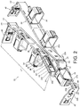
FIG. 2 is a diagram illustrating the cable management device in an angle of view according to the embodiment of the present invention; -
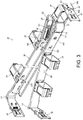
FIG. 3 is a diagram illustrating the cable management device in another angle of view according to the embodiment of the present invention; -
FIG. 4 is a diagram illustrating the cable management device having a first length according to the embodiment of the present invention; -
FIG. 5 is a diagram illustrating the cable management device having a second length according to the embodiment of the present invention; -
FIG. 6 is a diagram illustrating the cable management device applied to a rack and two cable management arms of the cable management device are close to each other according to the embodiment of the present invention; -
FIG. 7 is a diagram illustrating the cable management device applied to the rack and two cable management arms of the cable management device are unfolded relative to each other with the first length according to the embodiment of the present invention; and -
FIG. 8 is a diagram illustrating the cable management device applied to the rack and two cable management arms of the cable management device are unfolded relative to each other with the second length according to the embodiment of the present invention. - As shown in
FIG. 1 andFIG. 2 , acable management device 20 of an embodiment of the present invention includes a connectingmember 22, afirst component 24 and a firstcable management arm 26. Preferably, thecable management device 20 further includes asecond component 28 and a secondcable management arm 30. Wherein, thefirst component 24 and thesecond component 28 have a substantially same structural arrangement, and the firstcable management arm 26 and the secondcable management arm 30 have a substantially same structural arrangement. In addition, the structural relationship between thefirst component 24 and the firstcable management arm 26 is substantially the same as the structural relationship between thesecond component 28 and the secondcable management arm 30, but the present invention is not limited thereto. - The
first component 24 and thesecond component 28 are respectively connected to two different portions of the connectingmember 22. Preferably, thefirst component 24 is pivoted to afirst end portion 22a of the connectingmember 22 through a first shaft S1 (for example, the first shaft S1 penetrates through thefirst component 24 and thefirst end portion 22a of the connecting member 22). The firstcable management arm 26 is connected to thefirst component 24 in a stretchable and retractable manner. On the other hand, thesecond component 28 is pivoted to asecond end portion 22b of the connectingmember 22 through a second shaft S2 (for example, the second shaft S2 penetrates through thesecond component 28 and thesecond end portion 22b of the connecting member 22). The secondcable management arm 30 is connected to thesecond component 28 in a stretchable and retractable manner. In other words, the secondcable management arm 30 is connected to the connectingmember 22 through thesecond component 28. - Wherein, at least one cable management feature is arranged on the first
cable management arm 26, the secondcable management arm 30 and/or the connectingmember 22. Preferably, the firstcable management arm 26, the secondcable management arm 30 and the connectingmember 22 respectively include acable management feature 34, but it is not limited specifically. For example, thecable management features 34 can be arranged on the firstcable management arm 26 and the secondcable management arm 30, and the connectingmember 22 has no cable management feature. Alternatively, thecable management feature 34 can be only arranged on one of the firstcable management arm 26 and the secondcable management arm 30, and the connectingmember 22 and another one of the firstcable management arm 26 and the secondcable management arm 30 have no cable management feature. - Preferably, the
cable management feature 34 is detachably mounted on the firstcable management arm 26, the secondcable management arm 30 and the connectingmember 22. Alternatively, a predetermined cable management feature can be respectively formed on the firstcable management arm 26, the secondcable management arm 30 and the connectingmember 22. Thecable management device 20 is able to support or to accommodate cables of a carried object through the at least one cable management feature. Since the technical feature is obvious to a person having ordinary skill in the art, related description is omitted herein for simplicity. - Preferably, the first
cable management arm 26 has a structural feature corresponding to another structural feature of thefirst component 24, such that the firstcable management arm 26 is able to be moved linearly relative to thefirst component 24. For example, at least one arm section of the firstcable management arm 26 includes a first wall W1, a second wall W2 and a third wall W3 connected between the first wall W1 and the second wall W2. The first wall W1 and the second wall W2 are bent relative to the third wall W3, and a guidingpassage 33 is defined by the first wall W1, the second wall W2 and the third wall W3. In addition, the third wall W3 has a blockingportion 35 arranged in the guidingpassage 33. The blockingportion 35 includes a guiding end 35a and a blockingend 35b opposite to the guiding end 35a, wherein the guiding end 35a is arranged toward an inserted end of the guidingpassage 33. The guiding end 35a may be an inclined surface or an arc surface, and the blockingend 35b may be a perpendicular surface, but it is not limited thereto. On the other hand, at least one part of thefirst component 24 is located and accommodated in the guidingpassage 33. Wherein, thefirst component 24 includes afirst portion 24a, asecond portion 24b and athird portion 24c connected between thefirst portion 24a and thesecond portion 24b. In addition, acorresponding feature 25a is formed on anend 25 of thethird portion 24c, e.g., thecorresponding feature 25a is a bending edge, but it is not limited thereto, and thecorresponding feature 25a is corresponding to the blockingend 35b of theblocking portion 35. When assembling, through theend 25 of thefirst component 24 inserting into the inserted end of theguiding passage 33 of the firstcable management arm 26, thecorresponding feature 25a of theend 25 of thefirst component 24 abuts the guiding end 35a of theblocking portion 35 in advance and then passes over the guiding end 35a of theblocking portion 35. Thefirst portion 24a and the first wall W1 are able to support each other, and thesecond portion 24b and the second wall W2 are able to support each other, and thethird portion 24c and the third wall W3 are able to support each other. However, in another embodiment, the structural feature of the firstcable management arm 26 and the structural feature thefirst component 24 can also be a combination of an elongate hole (slot) and a protruded structure penetrating a portion of the elongate hole (slot), such that the firstcable management arm 26 is also able to be moved linearly relative to thefirst component 24. Wherein, an extending direction of the elongate hole (slot) is the same as a length direction of the first cable management arm 26(or the first component 24). Therefore, the technical mean of displacement of the firstcable management arm 26 relative to thefirst component 24 is not limited specifically. - Preferably, the
cable management device 20 further includes a firstelastic member 36 arranged between thefirst component 24 and the firstcable management arm 26. The firstelastic member 36 is configured to provide an elastic force to the firstcable management arm 26. In the present embodiment, the firstelastic member 36 is a resetting spring, and two ends of the firstelastic member 36 are mounted on a first mounting portion M1 of thefirst component 24 and a second mounting portion M2 of the firstcable management arm 26, but it is not limited specifically. According to the above arrangement, as shown inFIG. 2 , the firstelastic member 36 is able to provide an elastic force to the firstcable management arm 26, such that thefirst component 24 can be moved back to an original position relative to the firstcable management arm 26. When that thefirst component 24 is moved back to an original position relative to the firstcable management arm 26, anend 25 of thefirst component 24 can be blocked by the second mounting portion M2 of the firstcable management arm 26, such that the firstcable management arm 26 can be kept in a first predetermined position P1 relative to thefirst component 24. In other words, through being applied to an elastic force provided by firstelastic member 36 and being blocked by the second mounting portion M2, the firstcable management arm 26 is able to be kept in the first predetermined position P1 relative to thefirst component 24. When the firstcable management arm 26 is located at the first predetermined position P1 relative to thefirst component 24, thecable management device 20 has a first length L1. - Preferably, the
cable management device 20 further includes at least one supporting member configured to support one of the firstcable management arm 26 and the secondcable management arm 30. In the present embodiment, the at least one supporting member includes a first supportingmember 37a and a second supportingmember 37b connected to the first supportingmember 37a in a stretchable and retractable manner. The first supportingmember 37a and the second supportingmember 37b are configured to support one of a bottom of the firstcable management arm 26 and a bottom of the secondcable management arm 30. - Preferably, the
cable management device 20 further includes afirst mounting device 38, asecond mounting device 40 and athird mounting device 42 are respectively arranged on the firstcable management arm 26, the secondcable management arm 30 and the at least one supporting member (such as the second supportingmember 37b). Furthermore, the first mountingdevice 38 is pivoted to an end portion of the firstcable management arm 26 through a first pivot member X1 (for example, the first pivot member X1 penetrates the first mountingdevice 38 and the end portion of the first cable management arm 26). Thesecond mounting device 40 is pivot to an end portion of the secondcable management arm 30 through a second pivot member X2 (for example, the second pivot member X2 penetrates thesecond mounting device 40 and the end portion of the second cable management arm 30) . Thethird mounting device 42 is pivoted to a supportingbase 44 of the at least one supporting member through a third pivot member X3 (for example, the third pivot member X3 penetrates thethird mounting device 42 and the supportingbase 44 of the at least one supporting member). Preferably, the supportingbase 44 has a supportingportion 44a and alateral portion 44b substantially perpendicularly connected to the supportingportion 44a. The supportingportion 44a is connected (such as pivoted) to the at least one supporting member. Thethird mounting device 42 is pivoted to thelateral portion 44b through a third pivot member X3. - As shown in
FIG. 3 , thecable management device 20 further includes a secondelastic member 46 arranged between thesecond component 28 and the secondcable management arm 30. The secondelastic member 46 is configured to provide an elastic force to the secondcable management arm 30. In the present embodiment, the secondelastic member 46 is a resetting spring, and two ends of the secondelastic member 46 are respectively mounted on a first mounting portion M1 of thesecond component 28 and a second mounting portion M2 of the secondcable management arm 30, but the present invention is not limited thereto. As such, the secondelastic member 46 is able to provide an elastic force to the secondcable management arm 30, such that thesecond component 28 can be moved back to an original position relative to the secondcable management arm 30. When thesecond component 28 is moved back to an original position relative to the secondcable management arm 30, anend 29 of thesecond component 28 can be blocked by the second mounting portion M2 of the secondcable management arm 30, such that the secondcable management arm 30 can be kept in a first predetermined position P1 relative to thesecond component 28. In other words, through being applied to an elastic force provided by secondelastic member 46 and being blocked by the second mounting portion M2 of the secondcable management arm 30, the secondcable management arm 30 is able to be kept in the first predetermined position P1 relative to thesecond component 28. - As shown in
FIG. 4 , the secondcable management arm 30 is able to located at the first predetermined position P1 relative to thesecond component 28, such that thecable management device 20 has the first length L1. Preferably, by the secondelastic member 46 providing an elastic force, the secondcable management arm 30 is able to be kept in the first predetermined position P1 relative to thesecond component 28. It is noticed that the firstcable management arm 26 and thefirst component 24 are not shown inFIG. 4 . - As shown in
FIG. 5 , one of the cable management arms of the cable management device 20 (the firstcable management arm 26 or the second cable management arm 30) is able to be located on a second predetermined position P2 relative to the component (thefirst component 24 or the second component 28). In the present embodiment, the secondcable management arm 30 is able to be located on the second predetermined position P2 relative to thesecond component 28, such that thecable management device 20 has a second length L2 greater than the first length L1. Wherein, the secondelastic member 46 accumulates the elastic force. It is noticed that, the firstcable management arm 26 and thefirst component 24 are not shown inFIG. 5 . - As shown in
FIG. 6 , a connecting assembly according to the embodiment of the present invention includes a firstslide rail assembly 48 and thecable management device 20. Preferably, the connecting assembly further includes a secondslide rail assembly 50. The firstslide rail assembly 48 and the secondslide rail assembly 50 respectively includes afirst rail 52 and asecond rail 54, and thefirst rail 52 and thesecond rail 54 are movable relative each other. In the present embodiment, thefirst rail 52 is able to be mounted on afirst post 56a and asecond post 56b of a rack, and thesecond rail 54 carries a carried object 58 (such as an electronic apparatus), such that the carriedobject 58 is movable relative to thefirst rail 52 through thesecond rail 54. Wherein, thesecond rail 54 is located at a retracted position R relative to thefirst rail 52. -
FIG. 6 is a diagram illustrating the firstcable management arm 26 is able to be mounted (such as detachably mounted) on thesecond rail 54 of the firstslide rail assembly 48 through the first mountingdevice 38. The secondcable management arm 30 is able to be mounted (such as detachably mounted) on thefirst rail 52 of the firstslide rail assembly 48 through thesecond mounting device 40. The at least one supporting member(the first supportingmember 37a and the second supportingmember 37b) is able to be mounted (such as detachably mounted) on thefirst rail 52 of the secondslide rail assembly 50 through thethird mounting device 42. When thesecond rail 54 is located at the retracted position R relative to thefirst rail 52, the firstcable management arm 26 and the secondcable management arm 30 are close to each other. Wherein, the first supportingmember 37a and the second supportingmember 37b are configured to support one of a bottom of the firstcable management arm 26 and a bottom of the secondcable management arm 30. It is noticed that the firstelastic member 36 and the secondelastic member 46 are omitted inFIG. 6 to FIG. 8 . - As shown in
FIG. 7 , the firstcable management arm 26 is located at the first predetermined position P1 relative to thefirst component 24, such that thecable management device 20 has the first length L1. Wherein, thesecond rail 54 is able to be moved from the retracted position R to a first extension position E1 along an open direction D relative to thefirst rail 52, such that the firstcable management arm 26 and the secondcable management arm 30 are unfolded relative to each other. - As shown in
FIG. 8 , when thesecond rail 54 is further moved to a second extension position E2 along the open direction D relative thefirst rail 52, thesecond rail 54 is able to drive the firstcable management arm 26 to move to the second predetermined position P2 relative to thefirst component 24, such that thecable management device 20 has the second length L2 greater than the first length L1. According to the above arrangement, thecable management device 20 is adaptable to different slide rail assemblies having different extension length. In other words, when thesecond rail 54 is moved to the first extension position E1 relative to thefirst rail 52, the firstelastic member 36 is not stretched by thesecond rail 54 located at the first extension position E1. That is to say the firstelastic member 36 is able to keep the firstcable management arm 26 in the first predetermined position P1 relative to the first component 24 (please also refer toFIG. 2 ). When thesecond rail 54 is moved to the second extension position E2 relative to thefirst rail 52, the firstelastic member 36 is stretched by thesecond rail 54 located at the second extension position E2, such that the firstcable management arm 26 is able to be kept in the second predetermined position P2 relative to thefirst component 24 through the blockingend 35b of the blockingportion 35 of the firstcable management arm 26 abutting thecorresponding feature 25a of theend 25 of the first component 24 (please refer toFIG. 5 ). - It is noticed that in another embodiment, through the first mounting
device 38, thesecond mounting device 40 and thethird mounting device 42 being rotatable, the secondcable management arm 30 is able to be mounted on thesecond rail 54 of the secondslide rail assembly 50 by thesecond mounting device 40, and the firstcable management arm 26 is able to be mounted on thefirst rail 52 of the secondslide rail assembly 50 by the first mountingdevice 38, and the at least one supporting member is able to be mounted on thefirst rail 52 of the firstslide rail assembly 48 by thethird mounting device 42. In other words, thecable management device 20 is able to be applied to the firstslide rail assembly 48 on a left side of the rack, or applied to the secondslide rail assembly 50 on a right side of the rack. Therefore, thecable management device 20 is interchangeable between the left and right sides of the rack. - Compared to the prior art, the connecting assembly and the cable management device of the present invention have advantages over the prior art by the following perspectives:
- 1. The
first component 24 is connected to the connectingmember 22. The firstcable management arm 26 is connected to thefirst component 24 in a stretchable and retractable manner. Through the first cable management arm 26 (or the second cable management arm 30) being located at different predetermined positions, thecable management device 20 can have different length. According to the arrangement, thecable management device 20 can be applied to different slide rail assemblies having different extension length. - 2. The first
elastic member 36 is configured to provide an elastic force to the firstcable management arm 26, such that the firstcable management arm 26 is able to be kept in the first predetermined position P1 relative to thefirst component 24. - 3. The first
cable management arm 26 is able to be mounted on thefirst rail 52 of the firstslide rail assembly 48 through the first mountingdevice 38, and the secondcable management arm 30 is able to be mounted on thesecond rail 54 of the firstslide rail assembly 48 through thesecond mounting device 40. - 4. The
cable management device 20 is able to be applied to the firstslide rail assembly 48 on a left side of the rack or applied to the secondslide rail assembly 50 on a right side of the rack. Therefore, thecable management device 20 is interchangeable between the left and right sides of the rack.
Claims (15)
- A cable management device (20) applicable to a connecting assembly comprising a first slide rail assembly (48), the first slide rail assembly (48) comprising a first rail (52) and a second rail (54), the first rail (52) and the second rail (54) being movable relative to each other, the cable management device (20) characterized by:a connecting member (22);a first component (24) connected to the connecting member (22); anda first cable management arm (26) connected to the first component (24) in a stretchable and retractable manner, at least one cable management feature (34) being arranged on the first cable management arm (26).
- The cable management device (20) of claim 1, characterized in that the first component (24) is pivoted to the connecting member (22) .
- The cable management device (20) of claim 2, further characterized by:a second component (28) pivoted to the connecting member (22); anda second cable management arm (30) connected to the second component (28) in a stretchable and retractable manner.
- The cable management device (20) of claim 3, characterized in that the first component (24) is pivoted to a portion of the connecting member (22) through a first shaft (S1), the second component (28) is pivoted to another portion of the connecting member (22) different from the portion of the connecting member (22) through a second shaft (S2).
- The cable management device (20) of any of claims 1-4, further characterized by a first elastic member (36) arranged between the first component (24) and the first cable management arm (26).
- The cable management device (20) of claim 3 or 4, further characterized by a second elastic member (46) arranged between the second component (28) and the second cable management arm (30) .
- The cable management device (20) of claim 3 or 4, further characterized by at least one supporting member (37a, 37b) configured to support one of the first cable management arm (26) and the second cable management arm (30).
- The cable management device (20) of any of claims 1-7, characterized in that the first cable management arm (26) has a structural feature (W1, W2, W3) corresponding to another structural feature (24a, 24b, 24c) of the first component (24), such that the first cable management arm (26) is able to be moved linearly relative to the first component (24).
- The cable management device (20) of claim 7, characterized in that the at least one supporting member (37a, 37b) comprises a first supporting member (37a) and a second supporting member (37b) connected to the first supporting member (37a) in a stretchable and retractable manner, the first supporting member (37a) and the second supporting member (37b) are configured to support one of a bottom of the first cable management arm (26) and a bottom of the second cable management arm (30).
- A connecting assembly, characterized by:a first slide rail assembly (48) comprising a first rail (52) and a second rail (54), wherein the first rail (52) and the second rail (54) are movable relative to each other; anda cable management device (20) according to claim 1, further comprising;
a second cable management arm (30) connected to the connecting member (22);wherein the first cable management arm (26) is able to be mounted to the second rail (54) of the first slide rail assembly (48) through a first mounting device (38);wherein the second cable management arm (30) is able to be mounted to the first rail (52) of the first slide rail assembly (48) through a second mounting device (40). - The connecting assembly of claim 10, characterized in that the first component (24) is pivoted to the connecting member (22), the first cable management arm (26) is connected to the first component (24) in a stretchable and retractable manner.
- The connecting assembly of claim 11, characterized in that the second cable management arm (30) is connected to the connecting member (22) through a second component (28).
- The connecting assembly of claim 12, characterized in that the second component (28) is pivoted to the connecting member (22), the second cable management arm (30) is connected to the second component (28) in a stretchable and retractable manner, at least one cable management feature (34) is arranged on one of the first cable management arm (26) and the second cable management arm (30) .
- The connecting assembly of claim 13, further characterized by a second slide rail assembly (50) and at least one supporting member (37a, 37b), wherein the second slide rail assembly (50) comprises a first rail (52) and a second rail (54), the first rail (52) and the second rail (54) of the second slide rail assembly (50) are movable relative to each other, the at least one supporting member (37a, 37b) is able to be mounted on the first rail (52) of the second slide rail assembly (50) through a third mounting device (42), the at least one supporting member (37a, 37b) is configured to support one of the first cable management arm (26) and the second cable management arm (30).
- The connecting assembly of claim 14, characterized in that the first mounting device (38) is pivoted to the first cable management arm (26), the second mounting device (40) is pivoted to the second cable management arm (30), the third mounting device (42) is pivoted to the at least one supporting member (37a, 37b).
Applications Claiming Priority (1)
| Application Number | Priority Date | Filing Date | Title |
|---|---|---|---|
| TW108132167A TWI705636B (en) | 2019-09-04 | 2019-09-04 | Coupling assembly and cable management device thereof |
Publications (2)
| Publication Number | Publication Date |
|---|---|
| EP3790366A1 true EP3790366A1 (en) | 2021-03-10 |
| EP3790366B1 EP3790366B1 (en) | 2024-05-15 |
Family
ID=69156185
Family Applications (1)
| Application Number | Title | Priority Date | Filing Date |
|---|---|---|---|
| EP20150638.3A Active EP3790366B1 (en) | 2019-09-04 | 2020-01-08 | Connecting assembly and cable management device thereof |
Country Status (4)
| Country | Link |
|---|---|
| US (1) | US11153987B2 (en) |
| EP (1) | EP3790366B1 (en) |
| JP (1) | JP6941194B2 (en) |
| TW (1) | TWI705636B (en) |
Citations (4)
| Publication number | Priority date | Publication date | Assignee | Title |
|---|---|---|---|---|
| US8231014B2 (en) * | 2008-09-03 | 2012-07-31 | King Slide Works Co., Ltd. | Support slide assembly for a cable management arm |
| CN204392731U (en) * | 2014-12-30 | 2015-06-10 | 雅固拉国际精密工业(苏州)有限公司 | cable management bracket connector |
| US9867311B2 (en) * | 2016-02-22 | 2018-01-09 | Gslide Corporation | Server cable management structure |
| US10389100B2 (en) | 2017-08-18 | 2019-08-20 | King Slide Works Co., Ltd. | Cable management device and coupling assembly for rack system |
Family Cites Families (18)
| Publication number | Priority date | Publication date | Assignee | Title |
|---|---|---|---|---|
| US6303864B1 (en) * | 1999-12-22 | 2001-10-16 | Dell Products, L.P. | Connector arrangement and connecting method for cable management arms |
| US6305556B1 (en) * | 2000-10-26 | 2001-10-23 | Hewlett-Packard Company | Cable management solution for rack-mounted computers |
| US6945504B2 (en) | 2002-08-20 | 2005-09-20 | King Slide Works Co., Ltd. | Adjustable cable management arm for furniture |
| US6902069B2 (en) * | 2002-10-23 | 2005-06-07 | Dell Products L.P. | System and method for rack cable management |
| US7472795B2 (en) * | 2003-12-05 | 2009-01-06 | Pentair Electronic Packaging Company | Anti-sag management assembly |
| TWI276276B (en) | 2005-04-19 | 2007-03-11 | King Slide Works Co Ltd | Cable management arm assembly |
| CN101562958B (en) * | 2008-04-16 | 2012-11-21 | 鸿富锦精密工业(深圳)有限公司 | Wire-management device |
| US8379410B2 (en) * | 2009-10-30 | 2013-02-19 | Dell Products L.P. | Reversible cable management arm |
| US9144174B2 (en) * | 2012-12-07 | 2015-09-22 | King Slide Works Co., Ltd. | Cable management arm assembly |
| US9370121B2 (en) * | 2014-03-24 | 2016-06-14 | King Slide Works Co., Ltd. | Cable management device |
| TWI524615B (en) * | 2014-09-19 | 2016-03-01 | 川湖科技股份有限公司 | Support device for cable management arm and mounting assembly thereof |
| US9474182B1 (en) | 2015-03-26 | 2016-10-18 | King Slide Works Co., Ltd. | Slide rail assembly |
| TWI556712B (en) | 2015-05-05 | 2016-11-01 | King Slide Works Co Ltd | Cable management assembly |
| US9532483B1 (en) * | 2015-07-16 | 2016-12-27 | Nan Juen International Co., Ltd. | Quick release bracket assembly |
| TWI593340B (en) * | 2015-08-14 | 2017-07-21 | King Slide Works Co | Slide rail assembly and bracket device thereof |
| TWI605328B (en) | 2016-08-12 | 2017-11-11 | 川湖科技股份有限公司 | Cable management assembly and cable management device thereof |
| TWI670910B (en) * | 2017-11-13 | 2019-09-01 | 川湖科技股份有限公司 | Coupling assembly and cable management device thereof |
| TWI649512B (en) * | 2018-02-07 | 2019-02-01 | 川湖科技股份有限公司 | Connecting device |
-
2019
- 2019-09-04 TW TW108132167A patent/TWI705636B/en active
- 2019-12-11 US US16/711,402 patent/US11153987B2/en active Active
-
2020
- 2020-01-08 EP EP20150638.3A patent/EP3790366B1/en active Active
- 2020-01-28 JP JP2020011467A patent/JP6941194B2/en active Active
Patent Citations (4)
| Publication number | Priority date | Publication date | Assignee | Title |
|---|---|---|---|---|
| US8231014B2 (en) * | 2008-09-03 | 2012-07-31 | King Slide Works Co., Ltd. | Support slide assembly for a cable management arm |
| CN204392731U (en) * | 2014-12-30 | 2015-06-10 | 雅固拉国际精密工业(苏州)有限公司 | cable management bracket connector |
| US9867311B2 (en) * | 2016-02-22 | 2018-01-09 | Gslide Corporation | Server cable management structure |
| US10389100B2 (en) | 2017-08-18 | 2019-08-20 | King Slide Works Co., Ltd. | Cable management device and coupling assembly for rack system |
Also Published As
| Publication number | Publication date |
|---|---|
| TWI705636B (en) | 2020-09-21 |
| EP3790366B1 (en) | 2024-05-15 |
| TW202112022A (en) | 2021-03-16 |
| JP2021040474A (en) | 2021-03-11 |
| JP6941194B2 (en) | 2021-09-29 |
| US11153987B2 (en) | 2021-10-19 |
| US20210068298A1 (en) | 2021-03-04 |
Similar Documents
| Publication | Publication Date | Title |
|---|---|---|
| EP3352546A1 (en) | Slide rail assembly | |
| KR101921496B1 (en) | Case | |
| EP3738469B1 (en) | Slide rail assembly | |
| EP3154320B1 (en) | Slide rail assembly and bracket device thereof | |
| EP3398481B1 (en) | Slide rail assembly | |
| EP3614816B1 (en) | Coupling assembly and cable management device thereof | |
| US10292496B2 (en) | Bracket device | |
| EP3282529B1 (en) | Cable management assembly and cable management device thereof | |
| EP3157314A2 (en) | Slide rail assembly for rack system | |
| EP3440961A1 (en) | Slide rail assembly and rail kit thereof | |
| EP3157313B1 (en) | Support assembly and support device thereof | |
| EP3231325B1 (en) | Bracket device | |
| EP3292789A1 (en) | Slide rail assembly and rail kit thereof | |
| US20190053396A1 (en) | Cable Management Device and Connecting Assembly for Rack System | |
| EP3567994A1 (en) | Slide rail assembly and slide rail kit thereof | |
| EP3193569A1 (en) | Bracket device | |
| US20090267471A1 (en) | Sliding track for electronic devices | |
| EP3422830B1 (en) | Connecting assembly for rack system | |
| JP2016176570A (en) | Cable protection guide device | |
| EP3644695A1 (en) | Slide rail assembly | |
| EP3700311A1 (en) | Slide rail mechanism and supporting assembly thereof | |
| EP3790366B1 (en) | Connecting assembly and cable management device thereof | |
| EP2807906B1 (en) | Printing screen for surface mount devices | |
| EP3758459A1 (en) | Cable management assembly | |
| US11139645B2 (en) | Cable management assembly |
Legal Events
| Date | Code | Title | Description |
|---|---|---|---|
| PUAI | Public reference made under article 153(3) epc to a published international application that has entered the european phase |
Free format text: ORIGINAL CODE: 0009012 |
|
| STAA | Information on the status of an ep patent application or granted ep patent |
Free format text: STATUS: REQUEST FOR EXAMINATION WAS MADE |
|
| 17P | Request for examination filed |
Effective date: 20210105 |
|
| AK | Designated contracting states |
Kind code of ref document: A1 Designated state(s): AL AT BE BG CH CY CZ DE DK EE ES FI FR GB GR HR HU IE IS IT LI LT LU LV MC MK MT NL NO PL PT RO RS SE SI SK SM TR |
|
| AX | Request for extension of the european patent |
Extension state: BA ME |
|
| STAA | Information on the status of an ep patent application or granted ep patent |
Free format text: STATUS: EXAMINATION IS IN PROGRESS |
|
| 17Q | First examination report despatched |
Effective date: 20220218 |
|
| GRAP | Despatch of communication of intention to grant a patent |
Free format text: ORIGINAL CODE: EPIDOSNIGR1 |
|
| STAA | Information on the status of an ep patent application or granted ep patent |
Free format text: STATUS: GRANT OF PATENT IS INTENDED |
|
| INTG | Intention to grant announced |
Effective date: 20240201 |
|
| GRAS | Grant fee paid |
Free format text: ORIGINAL CODE: EPIDOSNIGR3 |
|
| GRAA | (expected) grant |
Free format text: ORIGINAL CODE: 0009210 |
|
| STAA | Information on the status of an ep patent application or granted ep patent |
Free format text: STATUS: THE PATENT HAS BEEN GRANTED |
|
| AK | Designated contracting states |
Kind code of ref document: B1 Designated state(s): AL AT BE BG CH CY CZ DE DK EE ES FI FR GB GR HR HU IE IS IT LI LT LU LV MC MK MT NL NO PL PT RO RS SE SI SK SM TR |
|
| REG | Reference to a national code |
Ref country code: CH Ref legal event code: EP |
|
| REG | Reference to a national code |
Ref country code: DE Ref legal event code: R096 Ref document number: 602020030801 Country of ref document: DE |
|
| REG | Reference to a national code |
Ref country code: IE Ref legal event code: FG4D |
|
| REG | Reference to a national code |
Ref country code: LT Ref legal event code: MG9D |
|
| REG | Reference to a national code |
Ref country code: DE Ref legal event code: R082 Ref document number: 602020030801 Country of ref document: DE Representative=s name: STRAUS, ALEXANDER, DIPL.-CHEM.UNIV. DR.PHIL., DE |
|
| REG | Reference to a national code |
Ref country code: NL Ref legal event code: MP Effective date: 20240515 |
|
| PG25 | Lapsed in a contracting state [announced via postgrant information from national office to epo] |
Ref country code: IS Free format text: LAPSE BECAUSE OF FAILURE TO SUBMIT A TRANSLATION OF THE DESCRIPTION OR TO PAY THE FEE WITHIN THE PRESCRIBED TIME-LIMIT Effective date: 20240915 |
|
| PG25 | Lapsed in a contracting state [announced via postgrant information from national office to epo] |
Ref country code: BG Free format text: LAPSE BECAUSE OF FAILURE TO SUBMIT A TRANSLATION OF THE DESCRIPTION OR TO PAY THE FEE WITHIN THE PRESCRIBED TIME-LIMIT Effective date: 20240515 |
|
| PG25 | Lapsed in a contracting state [announced via postgrant information from national office to epo] |
Ref country code: FI Free format text: LAPSE BECAUSE OF FAILURE TO SUBMIT A TRANSLATION OF THE DESCRIPTION OR TO PAY THE FEE WITHIN THE PRESCRIBED TIME-LIMIT Effective date: 20240515 Ref country code: HR Free format text: LAPSE BECAUSE OF FAILURE TO SUBMIT A TRANSLATION OF THE DESCRIPTION OR TO PAY THE FEE WITHIN THE PRESCRIBED TIME-LIMIT Effective date: 20240515 |
|
| PG25 | Lapsed in a contracting state [announced via postgrant information from national office to epo] |
Ref country code: GR Free format text: LAPSE BECAUSE OF FAILURE TO SUBMIT A TRANSLATION OF THE DESCRIPTION OR TO PAY THE FEE WITHIN THE PRESCRIBED TIME-LIMIT Effective date: 20240816 |
|
| PG25 | Lapsed in a contracting state [announced via postgrant information from national office to epo] |
Ref country code: PT Free format text: LAPSE BECAUSE OF FAILURE TO SUBMIT A TRANSLATION OF THE DESCRIPTION OR TO PAY THE FEE WITHIN THE PRESCRIBED TIME-LIMIT Effective date: 20240916 |
|
| REG | Reference to a national code |
Ref country code: AT Ref legal event code: MK05 Ref document number: 1687939 Country of ref document: AT Kind code of ref document: T Effective date: 20240515 |
|
| PG25 | Lapsed in a contracting state [announced via postgrant information from national office to epo] |
Ref country code: NL Free format text: LAPSE BECAUSE OF FAILURE TO SUBMIT A TRANSLATION OF THE DESCRIPTION OR TO PAY THE FEE WITHIN THE PRESCRIBED TIME-LIMIT Effective date: 20240515 |
|
| PG25 | Lapsed in a contracting state [announced via postgrant information from national office to epo] |
Ref country code: ES Free format text: LAPSE BECAUSE OF FAILURE TO SUBMIT A TRANSLATION OF THE DESCRIPTION OR TO PAY THE FEE WITHIN THE PRESCRIBED TIME-LIMIT Effective date: 20240515 |
|
| PG25 | Lapsed in a contracting state [announced via postgrant information from national office to epo] |
Ref country code: AT Free format text: LAPSE BECAUSE OF FAILURE TO SUBMIT A TRANSLATION OF THE DESCRIPTION OR TO PAY THE FEE WITHIN THE PRESCRIBED TIME-LIMIT Effective date: 20240515 |
|
| PG25 | Lapsed in a contracting state [announced via postgrant information from national office to epo] |
Ref country code: PL Free format text: LAPSE BECAUSE OF FAILURE TO SUBMIT A TRANSLATION OF THE DESCRIPTION OR TO PAY THE FEE WITHIN THE PRESCRIBED TIME-LIMIT Effective date: 20240515 |
|
| PG25 | Lapsed in a contracting state [announced via postgrant information from national office to epo] |
Ref country code: LV Free format text: LAPSE BECAUSE OF FAILURE TO SUBMIT A TRANSLATION OF THE DESCRIPTION OR TO PAY THE FEE WITHIN THE PRESCRIBED TIME-LIMIT Effective date: 20240515 |
|
| PG25 | Lapsed in a contracting state [announced via postgrant information from national office to epo] |
Ref country code: PT Free format text: LAPSE BECAUSE OF FAILURE TO SUBMIT A TRANSLATION OF THE DESCRIPTION OR TO PAY THE FEE WITHIN THE PRESCRIBED TIME-LIMIT Effective date: 20240916 Ref country code: PL Free format text: LAPSE BECAUSE OF FAILURE TO SUBMIT A TRANSLATION OF THE DESCRIPTION OR TO PAY THE FEE WITHIN THE PRESCRIBED TIME-LIMIT Effective date: 20240515 Ref country code: NO Free format text: LAPSE BECAUSE OF FAILURE TO SUBMIT A TRANSLATION OF THE DESCRIPTION OR TO PAY THE FEE WITHIN THE PRESCRIBED TIME-LIMIT Effective date: 20240815 Ref country code: NL Free format text: LAPSE BECAUSE OF FAILURE TO SUBMIT A TRANSLATION OF THE DESCRIPTION OR TO PAY THE FEE WITHIN THE PRESCRIBED TIME-LIMIT Effective date: 20240515 Ref country code: LV Free format text: LAPSE BECAUSE OF FAILURE TO SUBMIT A TRANSLATION OF THE DESCRIPTION OR TO PAY THE FEE WITHIN THE PRESCRIBED TIME-LIMIT Effective date: 20240515 Ref country code: IS Free format text: LAPSE BECAUSE OF FAILURE TO SUBMIT A TRANSLATION OF THE DESCRIPTION OR TO PAY THE FEE WITHIN THE PRESCRIBED TIME-LIMIT Effective date: 20240915 Ref country code: HR Free format text: LAPSE BECAUSE OF FAILURE TO SUBMIT A TRANSLATION OF THE DESCRIPTION OR TO PAY THE FEE WITHIN THE PRESCRIBED TIME-LIMIT Effective date: 20240515 Ref country code: GR Free format text: LAPSE BECAUSE OF FAILURE TO SUBMIT A TRANSLATION OF THE DESCRIPTION OR TO PAY THE FEE WITHIN THE PRESCRIBED TIME-LIMIT Effective date: 20240816 Ref country code: FI Free format text: LAPSE BECAUSE OF FAILURE TO SUBMIT A TRANSLATION OF THE DESCRIPTION OR TO PAY THE FEE WITHIN THE PRESCRIBED TIME-LIMIT Effective date: 20240515 Ref country code: ES Free format text: LAPSE BECAUSE OF FAILURE TO SUBMIT A TRANSLATION OF THE DESCRIPTION OR TO PAY THE FEE WITHIN THE PRESCRIBED TIME-LIMIT Effective date: 20240515 Ref country code: BG Free format text: LAPSE BECAUSE OF FAILURE TO SUBMIT A TRANSLATION OF THE DESCRIPTION OR TO PAY THE FEE WITHIN THE PRESCRIBED TIME-LIMIT Effective date: 20240515 Ref country code: AT Free format text: LAPSE BECAUSE OF FAILURE TO SUBMIT A TRANSLATION OF THE DESCRIPTION OR TO PAY THE FEE WITHIN THE PRESCRIBED TIME-LIMIT Effective date: 20240515 Ref country code: RS Free format text: LAPSE BECAUSE OF FAILURE TO SUBMIT A TRANSLATION OF THE DESCRIPTION OR TO PAY THE FEE WITHIN THE PRESCRIBED TIME-LIMIT Effective date: 20240815 |
|
| PG25 | Lapsed in a contracting state [announced via postgrant information from national office to epo] |
Ref country code: DK Free format text: LAPSE BECAUSE OF FAILURE TO SUBMIT A TRANSLATION OF THE DESCRIPTION OR TO PAY THE FEE WITHIN THE PRESCRIBED TIME-LIMIT Effective date: 20240515 |
|
| PG25 | Lapsed in a contracting state [announced via postgrant information from national office to epo] |
Ref country code: EE Free format text: LAPSE BECAUSE OF FAILURE TO SUBMIT A TRANSLATION OF THE DESCRIPTION OR TO PAY THE FEE WITHIN THE PRESCRIBED TIME-LIMIT Effective date: 20240515 |
|
| PG25 | Lapsed in a contracting state [announced via postgrant information from national office to epo] |
Ref country code: CZ Free format text: LAPSE BECAUSE OF FAILURE TO SUBMIT A TRANSLATION OF THE DESCRIPTION OR TO PAY THE FEE WITHIN THE PRESCRIBED TIME-LIMIT Effective date: 20240515 |
|
| PG25 | Lapsed in a contracting state [announced via postgrant information from national office to epo] |
Ref country code: RO Free format text: LAPSE BECAUSE OF FAILURE TO SUBMIT A TRANSLATION OF THE DESCRIPTION OR TO PAY THE FEE WITHIN THE PRESCRIBED TIME-LIMIT Effective date: 20240515 Ref country code: SK Free format text: LAPSE BECAUSE OF FAILURE TO SUBMIT A TRANSLATION OF THE DESCRIPTION OR TO PAY THE FEE WITHIN THE PRESCRIBED TIME-LIMIT Effective date: 20240515 |
|
| PG25 | Lapsed in a contracting state [announced via postgrant information from national office to epo] |
Ref country code: SM Free format text: LAPSE BECAUSE OF FAILURE TO SUBMIT A TRANSLATION OF THE DESCRIPTION OR TO PAY THE FEE WITHIN THE PRESCRIBED TIME-LIMIT Effective date: 20240515 |
|
| PG25 | Lapsed in a contracting state [announced via postgrant information from national office to epo] |
Ref country code: SM Free format text: LAPSE BECAUSE OF FAILURE TO SUBMIT A TRANSLATION OF THE DESCRIPTION OR TO PAY THE FEE WITHIN THE PRESCRIBED TIME-LIMIT Effective date: 20240515 Ref country code: SK Free format text: LAPSE BECAUSE OF FAILURE TO SUBMIT A TRANSLATION OF THE DESCRIPTION OR TO PAY THE FEE WITHIN THE PRESCRIBED TIME-LIMIT Effective date: 20240515 Ref country code: RO Free format text: LAPSE BECAUSE OF FAILURE TO SUBMIT A TRANSLATION OF THE DESCRIPTION OR TO PAY THE FEE WITHIN THE PRESCRIBED TIME-LIMIT Effective date: 20240515 Ref country code: EE Free format text: LAPSE BECAUSE OF FAILURE TO SUBMIT A TRANSLATION OF THE DESCRIPTION OR TO PAY THE FEE WITHIN THE PRESCRIBED TIME-LIMIT Effective date: 20240515 Ref country code: DK Free format text: LAPSE BECAUSE OF FAILURE TO SUBMIT A TRANSLATION OF THE DESCRIPTION OR TO PAY THE FEE WITHIN THE PRESCRIBED TIME-LIMIT Effective date: 20240515 Ref country code: CZ Free format text: LAPSE BECAUSE OF FAILURE TO SUBMIT A TRANSLATION OF THE DESCRIPTION OR TO PAY THE FEE WITHIN THE PRESCRIBED TIME-LIMIT Effective date: 20240515 |
|
| PG25 | Lapsed in a contracting state [announced via postgrant information from national office to epo] |
Ref country code: IT Free format text: LAPSE BECAUSE OF FAILURE TO SUBMIT A TRANSLATION OF THE DESCRIPTION OR TO PAY THE FEE WITHIN THE PRESCRIBED TIME-LIMIT Effective date: 20240515 |
|
| REG | Reference to a national code |
Ref country code: DE Ref legal event code: R097 Ref document number: 602020030801 Country of ref document: DE |
|
| PLBE | No opposition filed within time limit |
Free format text: ORIGINAL CODE: 0009261 |
|
| STAA | Information on the status of an ep patent application or granted ep patent |
Free format text: STATUS: NO OPPOSITION FILED WITHIN TIME LIMIT |
|
| 26N | No opposition filed |
Effective date: 20250218 |
|
| PG25 | Lapsed in a contracting state [announced via postgrant information from national office to epo] |
Ref country code: SI Free format text: LAPSE BECAUSE OF FAILURE TO SUBMIT A TRANSLATION OF THE DESCRIPTION OR TO PAY THE FEE WITHIN THE PRESCRIBED TIME-LIMIT Effective date: 20240515 |
|
| REG | Reference to a national code |
Ref country code: CH Ref legal event code: PL |
|
| PG25 | Lapsed in a contracting state [announced via postgrant information from national office to epo] |
Ref country code: SE Free format text: LAPSE BECAUSE OF FAILURE TO SUBMIT A TRANSLATION OF THE DESCRIPTION OR TO PAY THE FEE WITHIN THE PRESCRIBED TIME-LIMIT Effective date: 20240515 |
|
| PG25 | Lapsed in a contracting state [announced via postgrant information from national office to epo] |
Ref country code: MC Free format text: LAPSE BECAUSE OF FAILURE TO SUBMIT A TRANSLATION OF THE DESCRIPTION OR TO PAY THE FEE WITHIN THE PRESCRIBED TIME-LIMIT Effective date: 20240515 Ref country code: LU Free format text: LAPSE BECAUSE OF NON-PAYMENT OF DUE FEES Effective date: 20250108 |
|
| PG25 | Lapsed in a contracting state [announced via postgrant information from national office to epo] |
Ref country code: BE Free format text: LAPSE BECAUSE OF NON-PAYMENT OF DUE FEES Effective date: 20250131 |
|
| PG25 | Lapsed in a contracting state [announced via postgrant information from national office to epo] |
Ref country code: FR Free format text: LAPSE BECAUSE OF NON-PAYMENT OF DUE FEES Effective date: 20250131 |
|
| PG25 | Lapsed in a contracting state [announced via postgrant information from national office to epo] |
Ref country code: CH Free format text: LAPSE BECAUSE OF NON-PAYMENT OF DUE FEES Effective date: 20250131 |
|
| REG | Reference to a national code |
Ref country code: BE Ref legal event code: MM Effective date: 20250131 |
|
| PGFP | Annual fee paid to national office [announced via postgrant information from national office to epo] |
Ref country code: GB Payment date: 20251106 Year of fee payment: 7 |
|
| PGFP | Annual fee paid to national office [announced via postgrant information from national office to epo] |
Ref country code: IE Payment date: 20251106 Year of fee payment: 7 |
|
| PGFP | Annual fee paid to national office [announced via postgrant information from national office to epo] |
Ref country code: DE Payment date: 20251111 Year of fee payment: 7 |