EP3790334A1 - Information multiplexing transmission method and apparatus, and information receiving method and apparatus - Google Patents
Information multiplexing transmission method and apparatus, and information receiving method and apparatus Download PDFInfo
- Publication number
- EP3790334A1 EP3790334A1 EP18918339.5A EP18918339A EP3790334A1 EP 3790334 A1 EP3790334 A1 EP 3790334A1 EP 18918339 A EP18918339 A EP 18918339A EP 3790334 A1 EP3790334 A1 EP 3790334A1
- Authority
- EP
- European Patent Office
- Prior art keywords
- pusch
- uci
- multiplexing transmission
- selection
- selection criterion
- Prior art date
- Legal status (The legal status is an assumption and is not a legal conclusion. Google has not performed a legal analysis and makes no representation as to the accuracy of the status listed.)
- Granted
Links
- 230000005540 biological transmission Effects 0.000 title claims abstract description 210
- 238000000034 method Methods 0.000 title claims abstract description 56
- 238000010586 diagram Methods 0.000 description 38
- 238000004891 communication Methods 0.000 description 16
- 238000012545 processing Methods 0.000 description 15
- 238000005516 engineering process Methods 0.000 description 9
- 230000003287 optical effect Effects 0.000 description 5
- 230000003993 interaction Effects 0.000 description 4
- 230000005236 sound signal Effects 0.000 description 4
- 230000008569 process Effects 0.000 description 3
- 230000001133 acceleration Effects 0.000 description 2
- 230000009471 action Effects 0.000 description 2
- 230000008859 change Effects 0.000 description 2
- 238000013500 data storage Methods 0.000 description 2
- 238000007726 management method Methods 0.000 description 2
- 238000010295 mobile communication Methods 0.000 description 2
- 230000011664 signaling Effects 0.000 description 2
- 230000006978 adaptation Effects 0.000 description 1
- 238000003491 array Methods 0.000 description 1
- 230000009286 beneficial effect Effects 0.000 description 1
- 230000001413 cellular effect Effects 0.000 description 1
- 238000010276 construction Methods 0.000 description 1
- 238000013461 design Methods 0.000 description 1
- 238000003384 imaging method Methods 0.000 description 1
- 238000012986 modification Methods 0.000 description 1
- 230000004048 modification Effects 0.000 description 1
- 230000002093 peripheral effect Effects 0.000 description 1
- 230000009467 reduction Effects 0.000 description 1
- 230000003068 static effect Effects 0.000 description 1
Images


Classifications
-
- H—ELECTRICITY
- H04—ELECTRIC COMMUNICATION TECHNIQUE
- H04L—TRANSMISSION OF DIGITAL INFORMATION, e.g. TELEGRAPHIC COMMUNICATION
- H04L1/00—Arrangements for detecting or preventing errors in the information received
- H04L1/12—Arrangements for detecting or preventing errors in the information received by using return channel
- H04L1/16—Arrangements for detecting or preventing errors in the information received by using return channel in which the return channel carries supervisory signals, e.g. repetition request signals
- H04L1/18—Automatic repetition systems, e.g. Van Duuren systems
- H04L1/1829—Arrangements specially adapted for the receiver end
- H04L1/1864—ARQ related signaling
-
- H—ELECTRICITY
- H04—ELECTRIC COMMUNICATION TECHNIQUE
- H04W—WIRELESS COMMUNICATION NETWORKS
- H04W72/00—Local resource management
- H04W72/12—Wireless traffic scheduling
- H04W72/1263—Mapping of traffic onto schedule, e.g. scheduled allocation or multiplexing of flows
- H04W72/1268—Mapping of traffic onto schedule, e.g. scheduled allocation or multiplexing of flows of uplink data flows
-
- H—ELECTRICITY
- H04—ELECTRIC COMMUNICATION TECHNIQUE
- H04L—TRANSMISSION OF DIGITAL INFORMATION, e.g. TELEGRAPHIC COMMUNICATION
- H04L5/00—Arrangements affording multiple use of the transmission path
- H04L5/0001—Arrangements for dividing the transmission path
- H04L5/0003—Two-dimensional division
- H04L5/0005—Time-frequency
- H04L5/0007—Time-frequency the frequencies being orthogonal, e.g. OFDM(A), DMT
-
- H—ELECTRICITY
- H04—ELECTRIC COMMUNICATION TECHNIQUE
- H04L—TRANSMISSION OF DIGITAL INFORMATION, e.g. TELEGRAPHIC COMMUNICATION
- H04L5/00—Arrangements affording multiple use of the transmission path
- H04L5/003—Arrangements for allocating sub-channels of the transmission path
- H04L5/0044—Arrangements for allocating sub-channels of the transmission path allocation of payload
-
- H—ELECTRICITY
- H04—ELECTRIC COMMUNICATION TECHNIQUE
- H04L—TRANSMISSION OF DIGITAL INFORMATION, e.g. TELEGRAPHIC COMMUNICATION
- H04L5/00—Arrangements affording multiple use of the transmission path
- H04L5/003—Arrangements for allocating sub-channels of the transmission path
- H04L5/0053—Allocation of signaling, i.e. of overhead other than pilot signals
-
- H—ELECTRICITY
- H04—ELECTRIC COMMUNICATION TECHNIQUE
- H04L—TRANSMISSION OF DIGITAL INFORMATION, e.g. TELEGRAPHIC COMMUNICATION
- H04L5/00—Arrangements affording multiple use of the transmission path
- H04L5/0091—Signaling for the administration of the divided path
- H04L5/0094—Indication of how sub-channels of the path are allocated
-
- H—ELECTRICITY
- H04—ELECTRIC COMMUNICATION TECHNIQUE
- H04W—WIRELESS COMMUNICATION NETWORKS
- H04W72/00—Local resource management
- H04W72/04—Wireless resource allocation
- H04W72/044—Wireless resource allocation based on the type of the allocated resource
- H04W72/0446—Resources in time domain, e.g. slots or frames
-
- H—ELECTRICITY
- H04—ELECTRIC COMMUNICATION TECHNIQUE
- H04W—WIRELESS COMMUNICATION NETWORKS
- H04W72/00—Local resource management
- H04W72/04—Wireless resource allocation
- H04W72/044—Wireless resource allocation based on the type of the allocated resource
- H04W72/0453—Resources in frequency domain, e.g. a carrier in FDMA
-
- H—ELECTRICITY
- H04—ELECTRIC COMMUNICATION TECHNIQUE
- H04W—WIRELESS COMMUNICATION NETWORKS
- H04W72/00—Local resource management
- H04W72/20—Control channels or signalling for resource management
-
- H—ELECTRICITY
- H04—ELECTRIC COMMUNICATION TECHNIQUE
- H04W—WIRELESS COMMUNICATION NETWORKS
- H04W72/00—Local resource management
- H04W72/20—Control channels or signalling for resource management
- H04W72/21—Control channels or signalling for resource management in the uplink direction of a wireless link, i.e. towards the network
-
- H—ELECTRICITY
- H04—ELECTRIC COMMUNICATION TECHNIQUE
- H04W—WIRELESS COMMUNICATION NETWORKS
- H04W72/00—Local resource management
- H04W72/20—Control channels or signalling for resource management
- H04W72/23—Control channels or signalling for resource management in the downlink direction of a wireless link, i.e. towards a terminal
-
- H—ELECTRICITY
- H04—ELECTRIC COMMUNICATION TECHNIQUE
- H04L—TRANSMISSION OF DIGITAL INFORMATION, e.g. TELEGRAPHIC COMMUNICATION
- H04L5/00—Arrangements affording multiple use of the transmission path
- H04L5/003—Arrangements for allocating sub-channels of the transmission path
- H04L5/0053—Allocation of signaling, i.e. of overhead other than pilot signals
- H04L5/0055—Physical resource allocation for ACK/NACK
-
- H—ELECTRICITY
- H04—ELECTRIC COMMUNICATION TECHNIQUE
- H04L—TRANSMISSION OF DIGITAL INFORMATION, e.g. TELEGRAPHIC COMMUNICATION
- H04L5/00—Arrangements affording multiple use of the transmission path
- H04L5/003—Arrangements for allocating sub-channels of the transmission path
- H04L5/0053—Allocation of signaling, i.e. of overhead other than pilot signals
- H04L5/0057—Physical resource allocation for CQI
Definitions
- the disclosure relates to the technical field of communications, in particular to a method and apparatus for multiplexing transmission of information, a method and apparatus for receiving information, user equipment, a base station and a computer-readable storage medium.
- a new generation of novel Internet applications put forward higher requirements for a wireless communication technology, driving the wireless communication technology to evolve continuously to meet the needs of the applications.
- a cellular mobile communication technology is in the evolution stage of a new generation of technology.
- how to design improved uplink transmission to meet the needs of the system is an important subject.
- NR New Radio
- Different service types have different requirements for the wireless communication technology.
- eMBB enhanced Mobile Broad Band
- URLLC Ultra Reliable Low Latency Communication
- mMTC massive Machine Type Communication
- LCHs Logical Channels
- MAC Media Access Control
- Uplink control information includes a Hybrid Automatic Repeat reQuest (HARQ) indicator, a Scheduling Request (SR) and a Channel Status Indicator (CSI).
- HARQ Hybrid Automatic Repeat reQuest
- SR Scheduling Request
- CSI Channel Status Indicator
- the SR may be used by user equipment (UE) to apply to a base station for uplink resource scheduling.
- UE user equipment
- same UE may be configured with a variety of different SRs, each of which corresponds to one or more LCHs.
- the UCI can be transmitted through a physical uplink control channel (PUCCH).
- PUCCH physical uplink control channel
- UE may discard the transmission on the PUCCH and transmit the UCI including the HARQ indicator and the CSI through the PUSCH together with the uplink data.
- PAPR Peak to Average Power Ratio
- MPR Maximum Power Reduction
- Radio Access Network (RAN) 1 it was decided that when a PUCCH and a PUSCH were overlapped only partially in time-domain and had different starting symbols, the PUCCH and the PUSCH would also conduct multiplexing transmission when they met given timing requirements.
- UE may give up the transmission on the PUCCH, and the UCI transmitted on the PUCCH and content transmitted on the PUSCH may be multiplexed and then transmitted on the PUSCH.
- a method for multiplexing transmission of information and apparatus a method for receiving information and apparatus, user equipment (UE), a base station and a computer-readable storage medium are provided, in order to select a suitable PUSCH for multiplexing transmission when a Physical Uplink Control Channel (PUCCH) and a plurality of different Physical Uplink Shared Channels (PUSCHs) have an overlapping portion in time-domain.
- PUCCH Physical Uplink Control Channel
- PUSCHs Physical Uplink Shared Channels
- a method for multiplexing transmission of information is provided.
- the method may be applied to UE and may include:
- the selecting the PUSCH for the multiplexing transmission of the UCI carried in the PUCCH based on the selection criterion may include: taking a PUSCH with an earliest starting position or an earliest ending position in time-domain as the PUSCH for the multiplexing transmission of the UCI.
- the selecting the PUSCH for the multiplexing transmission of the UCI carried in the PUCCH based on the selection criterion may include: when a PUSCH of the plurality of PUSCHs is a PUSCH for uplink transmission based on a downlink dynamic scheduling (DL grant) and a PUSCH of the plurality of PUSCHs is a PUSCH for uplink transmission based on configured grant, taking the PUSCH for uplink transmission based on the DL grant as the PUSCH for the multiplexing transmission of the UCI.
- DL grant downlink dynamic scheduling
- the selecting the PUSCH for the multiplexing transmission of the UCI carried in the PUCCH based on the selection criterion may include: selecting a PUSCH with a maximum number of symbols in time-domain overlapped with the PUCCH as the PUSCH for the multiplexing transmission of the UCI.
- the selecting the PUSCH for the multiplexing transmission of the UCI carried in the PUCCH based on the selection criterion may include: selecting a PUSCH with a maximum number of resource units in an occupied time-frequency resource as the PUSCH for the multiplexing transmission of the UCI.
- the selecting the PUSCH for the multiplexing transmission of the UCI carried in the PUCCH based on the selection criterion may include:
- the method may further include:
- a method for receiving information is provided.
- the method may be applied to a base station and may include:
- the method may further include:
- an apparatus for multiplexing transmission of information may be applied to UE and may include:
- the selection module may include: a first selection submodule, configured to take a PUSCH with an earliest starting position or an earliest ending position in time-domain as the PUSCH for the multiplexing transmission of the UCI.
- the selection module may include: a second selection submodule, configured to, when a PUSCH of the plurality of PUSCHs is a PUSCH for uplink transmission based on a downlink dynamic scheduling (DL grant) and a PUSCH of the plurality of PUSCHs is a PUSCH for uplink transmission based on configured grant, take the PUSCH for uplink transmission based on the DL grant as the PUSCH for the multiplexing transmission of the UCI.
- a second selection submodule configured to, when a PUSCH of the plurality of PUSCHs is a PUSCH for uplink transmission based on a downlink dynamic scheduling (DL grant) and a PUSCH of the plurality of PUSCHs is a PUSCH for uplink transmission based on configured grant, take the PUSCH for uplink transmission based on the DL grant as the PUSCH for the multiplexing transmission of the UCI.
- DL grant downlink dynamic scheduling
- the selection module may include: a third selection submodule, configured to select a PUSCH with a maximum number of symbols in time-domain overlapped with the PUCCH as the PUSCH for the multiplexing transmission of the UCI.
- the selection module may include: a fourth selection submodule, configured to select a PUSCH with a maximum number of resource units in an occupied time-frequency resource as the PUSCH for the multiplexing transmission of the UCI.
- the selection module may include:
- the apparatus may further include:
- an apparatus for receiving information and the apparatus is applied to a base station, and may include:
- the apparatus may further include:
- the UE may include:
- a base station may include:
- a computer-readable storage medium storing computer instructions thereon. Operations of the method for multiplexing transmission of information may be implemented when the instructions are executed by a processor.
- a computer-readable storage medium storing computer instructions thereon. Operations of the method for receiving information may be implemented when the instructions are executed by a processor.
- a PUSCH for multiplexing transmission of UCI carried in the PUCCH may be selected based on a selection criterion.
- the transmission may be performed by multiplexing the UCI and the transmission content of the selected PUSCH in the selected PUSCH, so that a suitable PUSCH can be selected for the multiplexing transmission.
- a PUSCH for the multiplexing transmission of the UCI may be determined based on the selection criterion, and the UCI may be received from the determined PUSCH, thereby receiving the UCI.
- FIG. 1 is a flow diagram of a method for multiplexing transmission of information as shown in an exemplary embodiment of the disclosure. The embodiment is described from a User Equipment (UE) side. As shown in FIG. 1 , the method for multiplexing transmission of information includes the following operations.
- UE User Equipment
- a PUSCH for multiplexing transmission of Uplink Control Information (UCI) carried in the PUCCH is selected based on a selection criterion.
- UCI Uplink Control Information
- the method may further include: a selection criterion sent by a base station is received, and the selection criterion may also be agreed with a base station.
- the selecting the PUSCH for the multiplexing transmission of the UCI carried in the PUCCH based on the selection criterion may include, but is not limited to, any of the following situations.
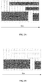
- Scenario 1 a PUSCH with an earliest starting position or an earliest ending position in time-domain is taken as the PUSCH for the multiplexing transmission of the UCI.
- PUCCH1 in FIG 2A carries UCI1
- PUCCH2 carries UCI2
- PUSCH1 carries data 1
- PUSCH2 carries data 2. Since a starting position of PUSCH1 in time-domain is earlier than that of PUSCH2, PUSCH1 is selected as the PUSCH for the multiplexing transmission of the UCI.
- Both the UCI of PUCCH1 and PUCCH2 are multiplexed in the PUSCH1.
- UCI1, UCI2 and data 1 may be transmitted by multiplexing in the PUSCH1.
- Scenario 2 when one PUSCH of the plurality of PUSCHs for uplink transmission is based on the DL grant and another PUSCH for uplink transmission is based on configured grant, a PUSCH for uplink transmission based on downlink dynamic scheduling (DL grant) is taken as the PUSCH for the multiplexing transmission of the UCI.
- DL grant downlink dynamic scheduling
- PUCCH1 in FIG 3A carries UCI1
- PUCCH2 carries UCI2
- PUSCH1 carries data 1
- PUSCH2 carries data 2
- PUSCH1 is a PUSCH for uplink transmission based on DL grant
- PUSCH2 is a PUSCH for uplink transmission based on configured grant.
- PUSCH1 may be selected as the PUSCH for the multiplexing transmission of the UCI.
- Both PUCCH1 and PUCCH2 may conduct multiplexing transmission of the UCI through PUSCH1.
- FIG. 3B multiplexing transmission of UCI1, UCI2 and data 1 may be conducted through PUSCH1.
- a PUSCH with the maximum number of symbols in time-domain overlapped with the PUCCH is selected as the PUSCH for the multiplexing transmission of the UCI.
- PUCCH1 in FIG 4A carries UCI1
- PUCCH2 carries UCI2
- PUSCH1 carries data 1
- PUSCH2 carries data 2.
- the number of overlapped symbols in time-domain of PUCCH1 and PUSCH1 is relatively large, therefore, UCI1 and data 1 are transmitted by multiplexing in PUSCH1.
- the number of overlapped symbols in time-domain of PUCCH2 and PUSCH2 is relatively large, thus UCI2 and data 2 are transmitted by multiplexing in PUSCH2.
- UCI1 and data 1 may be transmitted by multiplexing in PUSCH1
- UCI2 and data 2 may be transmitted by multiplexing in PUSCH2.
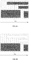
- a PUSCH with the maximum number of occupied resource units in a time-frequency resource is selected as the PUSCH for the multiplexing transmission of the UCI.
- PUCCH1 in FIG 5A carries UCI1
- PUCCH2 carries UCI2
- PUSCH1 carries data 1
- PUSCH2 carries data 2. Since the number of the resource units in time-domain resource occupied by PUSCH1 is relatively large, PUSCH1 is selected as the PUSCH for the multiplexing transmission of the UCI.
- UCI1, UCI2 and data 1 may be transmitted by multiplexing in PUSCH1.
- a corresponding selection criterion is determined according to a type of the UCI and pre-stored corresponding relationships between types of UCI and different selection criteria.
- a PUSCH is selected as the PUSCH for the multiplexing transmission of the UCI according to the determined selection criterion.
- the method may further include: the corresponding relationships between types of the UCI and the different selection criteria sent by a base station are received, or the corresponding relationships between types of the UCI and the different selection criteria may be agreed with a base station.
- the PUSCH namely PUSCH2
- the PUSCH with the earliest starting position in time-domain
- a report message that is a channel Status Indicator (CSI) the PUSCH, namely PUSCH1, with the maximum number of occupied resource units in the time-frequency resource may be selected as the PUSCH for the multiplexing transmission.
- HARQ and data 2 may be transmitted by multiplexing in PUSCH2, and CSI and data 1 may be transmitted by multiplexing in PUSCH1.
- multiplexing transmission is performed by multiplexing the UCI and transmission content of the selected PUSCH in the selected PUSCH.
- the multiplexing transmission may be performed by multiplexing the UCI and the transmission content of the selected PUSCH in the selected PUSCH.
- a PUSCH for multiplexing transmission of UCI carried in the PUCCH may be selected based on a selection criterion.
- the selected PUSCH may be used for performing the transmission by multiplexing the UCI and the transmission content of the selected PUSCH in the selected PUSCH, and thereby a suitable PUSCH is selected for the multiplexing transmission.
- FIG. 7 is a flow diagram of a method for receiving information as shown in an exemplary embodiment of the disclosure. The embodiment is described from a base station side. As shown in FIG. 7 , the method includes the operations as below.
- a PUSCH for multiplexing transmission of UCI is determined based on a selection criterion.
- the method may further include: a selection criterion is determined and sent to UE, or the selection criterion can also be agreed with the UE.
- the PUSCH for the multiplexing transmission of the UCI can be determined based on the selection criterion.
- the UCI is received from the determined PUSCH.
- a PUSCH for multiplexing transmission of UCI may be determined based on a selection criterion, and the UCI may be received from the determined PUSCH, thereby receiving the UCI.
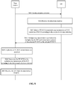
- FIG. 8 is a signaling flow diagram of the method for receiving information as shown in an exemplary embodiment of the disclosure. The embodiment is described from the angle of interaction between a base station and UE. As shown in FIG. 8 , the method includes following operations.
- the base station determines a selection criterion and sends the selection criterion to the UE.
- the UE receives the selection criterion.
- the UE selects a PUSCH for multiplexing transmission of UCI carried in the PUCCH according to the received selection criterion.
- the UE performs the transmission by multiplexing the UCI and transmission content of the selected PUSCH in the selected PUSCH.
- the base station receives the plurality of PUSCH transmissions.
- the base station determines the PUSCH for the multiplexing transmission of the UCI according to the determined selection criterion.
- the base station receives the UCI from the determined PUSCH.
- the UE can select a suitable PUSCH for the multiplexing transmission, and thus the base station can determine the PUSCH for the multiplexing transmission of UCI and receives the UCI from the determined PUSCH.
- FIG. 9 is a block diagram of an apparatus for multiplexing transmission of information as shown in an exemplary embodiment of the disclosure.
- the apparatus is arranged in UE.
- the apparatus includes a selection module 91 and a transmission module 92.
- the selection module 91 is configured to select a PUSCH for multiplexing transmission of UCI carried in a PUCCH based on a selection criterion when the PUCCH and a plurality of PUSCHs have an overlapping portion in time-domain.
- the transmission module 92 is configured to perform the transmission by multiplexing the UCI and transmission content of the selected PUSCH in the PUSCH selected by the selection module 91.
- the transmission may be performed by multiplexing the UCI and the transmission content of the selected PUSCH in the selected PUSCH.
- a PUSCH for multiplexing transmission of UCI carried in the PUCCH may be selected based on a selection criterion, and the transmission may be performed by multiplexing the UCI and the transmission content of the selected PUSCH in the selected PUSCH.
- FIG. 10 is a block diagram of another apparatus for multiplexing transmission of information as shown in an exemplary embodiment of the disclosure.
- the selection module 91 may include: a first selection submodule 911.
- the first selection submodule 911 is configured to take a PUSCH with an earliest starting position or an earliest ending position in time-domain as the PUSCH for the multiplexing transmission of the UCI.
- PUCCH1 in FIG. 2A carries UCI1
- PUCCH2 carries UCI2
- PUSCH1 carries data 1
- PUSCH2 carries data 2. Since a starting position of PUSCH1 in the time-domain is earlier than that of PUSCH2, PUSCH1 may be selected as the PUSCH for the multiplexing transmission of the UCI. Both the UCI of PUCCH1 and PUCCH2 are multiplexed in the PUSCH1. As shown in FIG. 2B , UCI1, UCI2 and data 1 may be transmitted by multiplexing in the PUSCH1.
- a PUSCH with an earliest starting position or an earliest ending position in time-domain is adopted as the PUSCH for the multiplexing transmission of the UCI, which provides a condition for subsequent multiplexing transmission of the UCI in the selected PUSCH.
- the implementation is simple.
- FIG. 11 is a block diagram of yet another apparatus for multiplexing transmission of information as shown in an exemplary embodiment of the disclosure.
- the selection module 91 may include a second selection submodule 912.
- the second selection submodule 912 is configured to take a PUSCH for uplink transmission based on DL grant as the PUSCH for the multiplexing transmission of the UCI when a PUSCH of the plurality of PUSCHs is a PUSCH for uplink transmission based on the DL grant and a PUSCH of the plurality of PUSCHs is a PUSCH for uplink transmission based on configured grant.
- a PUSCH for uplink transmission based on DL grant is adopted as the PUSCH for multiplexing transmission of UCI, which provides a condition for subsequent multiplexing transmission of the UCI in the selected PUSCH.
- Such implementation is simple.
- FIG. 12 is a block diagram of yet another apparatus for multiplexing transmission of information as shown in an exemplary embodiment of the disclosure.
- the selection module 91 may include a third selection submodule 913.
- the third selection submodule 913 is configured to select a PUSCH with the maximum number of symbols in time-domain overlapped with the PUCCH as the PUSCH for the multiplexing transmission of the UCI.
- a PUSCH with the maximum number of symbols in time-domain overlapped with the PUCCH is selected as the PUSCH for multiplexing transmission of UCI, which provides a condition for subsequent multiplexing transmission of the UCI in the selected PUSCH,
- the implementation is simple.
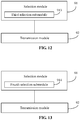
- FIG. 13 is a block diagram of yet another apparatus for multiplexing transmission of information as shown in an exemplary embodiment of the disclosure.
- the selection module 91 may include a fourth selection submodule 914.
- the fourth selection submodule 914 is configured to select a PUSCH with the maximum number of resource units in an occupied time-frequency resource as the PUSCH for the multiplexing transmission of the UCI.
- a PUSCH with the maximum number of resource units in the occupied time-frequency resource is selected as the PUSCH for multiplexing transmission of UCI, which provides a condition for subsequent multiplexing transmission of the UCI in the selected PUSCH,
- the implementation is simple.
- FIG. 14 is a block diagram of yet another apparatus for multiplexing transmission of information as shown in an exemplary embodiment of the disclosure.
- the selection module 91 may include a determining submodule 915 and a fifth selection submodule 916.
- the determining submodule 915 is configured to determine a corresponding selection criterion according to a type of the UCI and pre-stored corresponding relationships between types of UCI and different selection criteria;
- the fifth determining submodule 916 is configured to select a PUSCH as the PUSCH for the multiplexing transmission of the UCI based on the selection criterion determined by the determining submodule 915.
- a PUSCH may be selected as the PUSCH for multiplexing transmission of UCI according to a determined selection criterion, which provides a condition for subsequent multiplexing transmission of the UCI in the selected PUSCH,
- a determined selection criterion which provides a condition for subsequent multiplexing transmission of the UCI in the selected PUSCH
- FIG. 15 is a block diagram of yet another apparatus for multiplexing transmission of information as shown in an exemplary embodiment of the disclosure. As shown in FIG. 15 , on the basis of the embodiment shown in FIG. 9 above, the apparatus may further include a receiving module 93 or an agreeing module 94.
- the receiving module 93 is configured to receive the selection criterion or the corresponding relationships between types of UCI and different selection criteria from a base station.
- the agreeing module 94 is configured to agree the selection criterion or the corresponding relationships between types of UCI and different selection criteria with the base station.
- the selection criterion may be determined or agreed, which provides a condition for subsequent selection of the PUSCH for the multiplexing transmission of the UCI based on the selection criterion.
- FIG. 16 is a block diagram of an apparatus for receiving information as shown in an exemplary embodiment of the disclosure.
- the apparatus can be located in a base station. As shown in FIG. 16 , the apparatus includes:
- a PUSCH for multiplexing transmission of UCI may be determined based on a selection criterion, and the UCI may be received from the determined PUSCH, thereby receiving the UCI.
- FIG. 17 is a block diagram of another apparatus for receiving information as shown in an exemplary embodiment of the disclosure. As shown in FIG. 17 , on the basis of the embodiment shown in FIG. 16 above, the apparatus may further include a first determining and sending module 164, a second determining and sending module 165 or an agreeing module 166.
- the first determining and sending module 164 is configured to determine the selection criterion and send the selection criterion to UE.
- the second determining and sending module 165 is configured to determine corresponding relationships between the type of the UCI and different selection criteria and send the corresponding relationships between types of UCI and different selection criteria to the UE.
- the agreeing module 166 is configured to agree the selection criterion or the corresponding relationships between types of UCI and different selection criteria with the UE.
- a selection criterion may be determined and sent to UE or may be agreed with the UE, which enables the UE to select a PUSCH for multiplexing transmission of UCI based on the selection criterion.
- FIG. 18 is a block diagram of an apparatus suitable for multiplexing transmission of information as shown in an exemplary embodiment of the disclosure.
- the apparatus 1800 may be user equipment such as a mobile phone, a computer, a digital broadcasting terminal, a message transceiver, a game console, tablet equipment, medical equipment, fitness equipment, and a personal digital assistant.
- the apparatus 1800 may include one or more of the following components: a processing component 1802, a memory 1804, a power component 1806, a multimedia component 1808, an audio component 1810, an Input/Output (I/O) interface 1812, a sensor component 1814, and a communication component 1816.
- a processing component 1802 a memory 1804, a power component 1806, a multimedia component 1808, an audio component 1810, an Input/Output (I/O) interface 1812, a sensor component 1814, and a communication component 1816.
- a processing component 1802 a memory 1804, a power component 1806, a multimedia component 1808, an audio component 1810, an Input/Output (I/O) interface 1812, a sensor component 1814, and a communication component 1816.
- I/O Input/Output
- the processing component 1802 generally controls overall operations of the apparatus 1800, such as operations related to displaying, telephone calls, data communications, camera operations, and recording operations.
- the processing component 1802 may include one or more processors 1820 to execute instructions, so as to complete all or part of the operations of the method described above.
- the processing component 1802 may include one or more modules to facilitate the interaction between the processing component 1802 and other components.
- the processing component 1802 may include a multimedia module to facilitate the interaction between the multimedia component 1808 and the processing component 1802.
- One of the processors 1820 of the processing component 1802 may be configured to:
- the memory 1804 is configured to store various types of data to support the operation of the apparatus 1800. Examples of such data include instructions for any application program or method operated on the apparatus 1800, contact data, phone book data, messages, pictures, videos, and the like.
- the memory 1804 may be implemented by any type of volatile or non-volatile storage devices or a combination thereof, such as a Static Random Access Memory (SRAM), an Electrically Erasable Programmable Read-Only Memory (EEPROM), a Programming Read-Only Memory (EPROM), a Programmable Read-Only Memory (PROM), a Read-Only Memory (ROM), a magnetic memory, a flash memory, a magnetic disk or an optical disk.
- SRAM Static Random Access Memory
- EEPROM Electrically Erasable Programmable Read-Only Memory
- EPROM Programming Read-Only Memory
- PROM Programmable Read-Only Memory
- ROM Read-Only Memory
- the power component 1806 is configured to provide power for various components of the apparatus 1800.
- the power component 1806 may include a power management system, one or more power supplies, and other components associated with generating, managing, and distributing power for the apparatus 1800.
- the multimedia component 1808 may include a screen providing an output interface between the apparatus 1800 and a user.
- the screen may include an LCD and a TP. If it includes the TP, the screen may be implemented as a touch screen to receive an input signal from a user.
- the TP includes one or more touch sensors to sense touch, swipe, and gestures on the TP. The touch sensors may not only sense a boundary of a touch or swipe action, but also detect a time of duration and a pressure associated with the touch or swipe action.
- the multimedia component 1808 includes a front camera and/or a rear camera. The front camera and the rear camera may receive external multimedia data while the apparatus 1800 is in an operation mode, such as a photographing mode or a video mode. Each of the front camera and rear camera may be a fixed optical lens system or may have focal lengths and optical zoom capabilities.
- the audio component 1810 is configured to output and/or input audio signals.
- the audio component 1810 includes a microphone (MIC), and the microphone is configured to receive an external audio signal when the apparatus 1800 is in an operation mode, such as a calling mode, a recording mode, and a voice identification mode.
- the received audio signals may be further stored in the memory 1804 or transmitted via the communication component 1816.
- the audio component 1810 may further include a speaker to output audio signals.
- the I/O interface 1812 is configured to provide an interface between the processing component 1802 and peripheral interface modules, which may be keyboards, click wheels, buttons, etc. These buttons may include, but are not limited to: a home button, a volume button, a start button, and a lock button.
- the sensor component 1814 may include one or more sensors configured to provide various aspects of state assessment for the apparatus 1800.
- the sensor component 1814 may detect an on/off status of the apparatus 1800, and relative positioning of components.
- the component is a display and a keypad of the apparatus 1800.
- the sensor component 1814 may also detect a change in position of the apparatus 1800 or a component of the apparatus 1800, presence or absence of user contact with the apparatus 1800, an orientation or an acceleration/deceleration of the apparatus 1800, and a change in temperature of the apparatus 1800.
- the sensor component 1814 may include a proximity sensor configured to detect the presence of objects nearby without any physical contact.
- the sensor component 1814 may also include light sensors, such as CMOS or CCD image sensors, for use in imaging applications.
- the sensor component 1814 may also include an acceleration sensor, a gyroscope sensor, a magnetic sensor, a pressure sensor, or a temperature sensor.
- the communication component 1816 is configured to facilitate wired or wireless communications between the apparatus 1800 and other devices.
- the apparatus 1800 may access a wireless network based on a communication standard, such as WiFi, 2G or 6G, or a combination thereof.
- the communication component 1816 receives a broadcast signal or broadcast related information from an external broadcast management system via a broadcast channel.
- the communication component 1816 further includes a Near Field Communication (NFC) module to promote short-range communications.
- NFC Near Field Communication
- the NFC module may be implemented based on a Radio Frequency Identification (RFID) technology, an Infrared Data Association (IrDA), an Ultra-Wide Band (UWB) technology, a Bluetooth (BT) technology and other technologies.
- RFID Radio Frequency Identification
- IrDA Infrared Data Association
- UWB Ultra-Wide Band
- BT Bluetooth
- the apparatus 1800 may be implemented by one or more Application-Specific Integrated Circuits (ASICs), Digital Signal Processors (DSPs), Digital Signal Processing Devices (DSPDs), Programmable Logic Devices (PLDs), Field Programmable Gate Arrays (FPGAs), controllers, microcontrollers, microprocessors, or other electronic components to perform the above method.
- ASICs Application-Specific Integrated Circuits
- DSPs Digital Signal Processors
- DSPDs Digital Signal Processing Devices
- PLDs Programmable Logic Devices
- FPGAs Field Programmable Gate Arrays
- controllers microcontrollers, microprocessors, or other electronic components to perform the above method.
- a non-transitory computer-readable storage medium storing instructions, such as the memory 1804 storing instructions.
- the above instructions may be executed by the processor 1820 of the apparatus 1800 to complete the foregoing method.
- the non-transitory computer-readable storage medium may be a Read Only Memory (ROM), a Random Access Memory (RAM), a CD-ROM, a magnetic tape, a floppy disc, an optical data storage device, and the like.
- FIG. 19 is a block diagram illustrating an apparatus suitable for multiplexing transmission of information according to an exemplary embodiment.
- the apparatus 1900 may be provided as a base station.
- the apparatus 1900 includes a processing component 1922, a wireless transmitting/receiving component 1924, an antenna component 1926 and a specific signal processing part of a wireless interface.
- the processing component 1922 may further include one or more processors.
- One of the processors in the processing component 1922 may be configured to:
- a non-transitory computer-readable storage medium storing instructions is further provided.
- the above instructions may be executed by the processing component 1922 of the apparatus 1900 to implement the above method for receiving information.
- the non-transitory computer-readable storage medium may be a Read Only Memory (ROM), a Random Access Memory (RAM), a CD-ROM, a magnetic tape, a floppy disc, an optical data storage device, and the like.
- the apparatus embodiments described above are merely illustrative.
- the units illustrated as separate elements may or may not be physically separate.
- the elements shown as units may or may not be physical units, i.e., may be arranged in one place, or may be distributed in a plurality of network units. Some or all of the modules may be selected according to actual needs to achieve the solutions of the embodiments. Those ordinarily skilled in the art would understand and practice without involving any inventive effort.
Abstract
Description
- The disclosure relates to the technical field of communications, in particular to a method and apparatus for multiplexing transmission of information, a method and apparatus for receiving information, user equipment, a base station and a computer-readable storage medium.
- A new generation of novel Internet applications put forward higher requirements for a wireless communication technology, driving the wireless communication technology to evolve continuously to meet the needs of the applications. A cellular mobile communication technology is in the evolution stage of a new generation of technology. In a new generation of mobile communication system, how to design improved uplink transmission to meet the needs of the system is an important subject.
- Flexible configurations of multiple service types need to be supported in a New Radio (NR). Different service types have different requirements for the wireless communication technology. For example, the main requirement of enhanced Mobile Broad Band (eMBB) focuses on large bandwidth, high rate and other aspects. The main requirement of Ultra Reliable Low Latency Communication (URLLC) focuses on high reliability and low delay. The main requirement of massive Machine Type Communication (mMTC) focuses on a large number of connections. A variety of Logical Channels (LCHs) are defined in a Media Access Control (MAC) layer in order to support services with different QoS requirements at the same time.
- Uplink control information (UCI) includes a Hybrid Automatic Repeat reQuest (HARQ) indicator, a Scheduling Request (SR) and a Channel Status Indicator (CSI). The SR may be used by user equipment (UE) to apply to a base station for uplink resource scheduling. In the NR, in order to support various services with different QoS requirements, same UE may be configured with a variety of different SRs, each of which corresponds to one or more LCHs.
- The UCI can be transmitted through a physical uplink control channel (PUCCH). In addition, when transmission of the HARQ indicator and the CSI on the PUCCH and transmission of uplink data on a physical uplink shared channel (PUSCH) are overlapped in time-domain (starting symbol positions are the same), UE may discard the transmission on the PUCCH and transmit the UCI including the HARQ indicator and the CSI through the PUSCH together with the uplink data. In this way, the single-carrier characteristic of uplink transmission can be ensured and a better Peak to Average Power Ratio (PAPR) and a lower Maximum Power Reduction (MPR) can be obtained.
- In the last Radio Access Network (RAN) 1 meeting, it was decided that when a PUCCH and a PUSCH were overlapped only partially in time-domain and had different starting symbols, the PUCCH and the PUSCH would also conduct multiplexing transmission when they met given timing requirements. According to an existing solution, when a PUCCH and a PUSCH conduct multiplexing transmission, UE may give up the transmission on the PUCCH, and the UCI transmitted on the PUCCH and content transmitted on the PUSCH may be multiplexed and then transmitted on the PUSCH.
- However, when a PUCCH and a plurality of different PUSCHs have an overlapping portion in time-domain, how to select a suitable PUSCH for multiplexing transmission is a technical problem that needs to be solved.
- In view of this, a method for multiplexing transmission of information and apparatus, a method for receiving information and apparatus, user equipment (UE), a base station and a computer-readable storage medium are provided, in order to select a suitable PUSCH for multiplexing transmission when a Physical Uplink Control Channel (PUCCH) and a plurality of different Physical Uplink Shared Channels (PUSCHs) have an overlapping portion in time-domain.
- According to a first aspect of embodiments of the disclosure, a method for multiplexing transmission of information is provided. The method may be applied to UE and may include:
- when a PUCCH and a plurality of PUSCHs have an overlapping portion in time-domain, selecting a PUSCH for multiplexing transmission of Uplink Control Information (UCI) carried in the PUCCH based on a selection criterion; and
- performing multiplexing transmission by multiplexing the UCI and transmission content of the selected PUSCH in the selected PUSCH.
- In an embodiment, the selecting the PUSCH for the multiplexing transmission of the UCI carried in the PUCCH based on the selection criterion may include:
taking a PUSCH with an earliest starting position or an earliest ending position in time-domain as the PUSCH for the multiplexing transmission of the UCI. - In an embodiment, the selecting the PUSCH for the multiplexing transmission of the UCI carried in the PUCCH based on the selection criterion may include:
when a PUSCH of the plurality of PUSCHs is a PUSCH for uplink transmission based on a downlink dynamic scheduling (DL grant) and a PUSCH of the plurality of PUSCHs is a PUSCH for uplink transmission based on configured grant, taking the PUSCH for uplink transmission based on the DL grant as the PUSCH for the multiplexing transmission of the UCI. - In an embodiment, the selecting the PUSCH for the multiplexing transmission of the UCI carried in the PUCCH based on the selection criterion may include:
selecting a PUSCH with a maximum number of symbols in time-domain overlapped with the PUCCH as the PUSCH for the multiplexing transmission of the UCI. - In an embodiment, the selecting the PUSCH for the multiplexing transmission of the UCI carried in the PUCCH based on the selection criterion may include:
selecting a PUSCH with a maximum number of resource units in an occupied time-frequency resource as the PUSCH for the multiplexing transmission of the UCI. - In an embodiment, the selecting the PUSCH for the multiplexing transmission of the UCI carried in the PUCCH based on the selection criterion may include:
- determining the selection criterion according to a type of the UCI and pre-stored corresponding relationships between types of UCI and different selection criteria; and
- selecting a PUSCH as the PUSCH for the multiplexing transmission of the UCI according to the determined selection criterion.
- In an embodiment, the method may further include:
- receiving the selection criterion or the corresponding relationships between types of UCI and different selection criteria from a base station; or
- agreeing the selection criterion or the corresponding relationships between types of UCI and different selection criteria with a base station.
- According to a second aspect of the embodiments of the disclosure, a method for receiving information is provided. The method may be applied to a base station and may include:
- receiving a plurality of PUSCH transmissions;
- determining a PUSCH for multiplexing transmission of UCI based on a selection criterion; and
- receiving the UCI from the determined PUSCH.
- In an embodiment, the method may further include:
- determining the selection criterion and sending the selection criterion to UE; or
- determining corresponding relationships between types of UCI and different selection criteria and sending the corresponding relationships between types of UCI and different selection criteria to UE; or
- agreeing the selection criterion or corresponding relationships between types of UCI and different selection criteria with UE.
- According to a third aspect of the embodiments of the disclosure, an apparatus for multiplexing transmission of information is provided. The apparatus may be applied to UE and may include:
- a selection module, configured to select a PUSCH for multiplexing transmission of UCI carried in a PUCCH based on a selection criterion when the PUCCH and a plurality of PUSCHs have an overlapping portion in time-domain; and
- a transmission module, configured to perform multiplexing transmission by multiplexing the UCI and transmission content of the selected PUSCH in the selected PUSCH.
- In an embodiment, the selection module may include:
a first selection submodule, configured to take a PUSCH with an earliest starting position or an earliest ending position in time-domain as the PUSCH for the multiplexing transmission of the UCI. - In an embodiment, the selection module may include:
a second selection submodule, configured to, when a PUSCH of the plurality of PUSCHs is a PUSCH for uplink transmission based on a downlink dynamic scheduling (DL grant) and a PUSCH of the plurality of PUSCHs is a PUSCH for uplink transmission based on configured grant, take the PUSCH for uplink transmission based on the DL grant as the PUSCH for the multiplexing transmission of the UCI. - In an embodiment, the selection module may include:
a third selection submodule, configured to select a PUSCH with a maximum number of symbols in time-domain overlapped with the PUCCH as the PUSCH for the multiplexing transmission of the UCI. - In an embodiment, the selection module may include:
a fourth selection submodule, configured to select a PUSCH with a maximum number of resource units in an occupied time-frequency resource as the PUSCH for the multiplexing transmission of the UCI. - In an embodiment, the selection module may include:
- a determining submodule, configured to determine the selection criterion according to a type of the UCI and pre-stored corresponding relationships between types of UCI and different selection criteria; and
- a fifth selection submodule, configured to select a PUSCH as the PUSCH for the multiplexing transmission of the UCI based on the selection criterion determined by the determining submodule.
- In an embodiment, the apparatus may further include:
- a receiving module, configured to receive the selection criterion or the corresponding relationships between types of UCI and different selection criteria from a base station; or
- an agreeing module, configured to agree the selection criterion or the corresponding relationships between types of UCI and different selection criteria with a base station.
- According to a fourth aspect of the embodiments of the disclosure, provided is an apparatus for receiving information, and the apparatus is applied to a base station, and may include:
- a first receiving module, configured to receive a plurality of PUSCH transmissions;
- a determining module, configured to determine a PUSCH for multiplexing transmission of UCI from the plurality of PUSCHs received by the first receiving module based on a selection criterion; and
- a second receiving module, configured to receive the UCI from the PUSCH determined by the determining module.
- In an embodiment, the apparatus may further include:
- a first determining and sending module, configured to determine the selection criterion and send the selection criterion to UE; or
- a second determining and sending module, configured to determine corresponding relationships between types of UCI and different selection criteria and send the corresponding relationships between types of UCI and different selection criteria to UE; or
- an agreeing module, configured to agree the selection criterion or corresponding relationships between types of UCI and different selection criteria with UE.
- According to a fifth aspect of the embodiments of the disclosure, UE is provided. The UE may include:
- a processor; and
- a memory, configured to store instructions executable by the processor;
- wherein the processor is configured to:
- select a PUSCH for multiplexing transmission of UCI carried in a PUCCH based on a selection criterion when the PUCCH and a plurality of PUSCHs have an overlapping portion in time-domain; and
- perform multiplexing transmission by multiplexing the UCI and transmission content of the selected PUSCH in the selected PUSCH.
- According to a sixth aspect of the embodiments of the disclosure, a base station is provided. The base station may include:
- a processor; and
- a memory, configured to store instructions executable by the processor;
- wherein the processor is configured to:
- receive a plurality of PUSCH transmissions;
- determine a PUSCH for multiplexing transmission of UCI based on a selection criterion; and
- receive the UCI from the determined PUSCH.
- According to a seventh aspect of the embodiments of the disclosure, provided is a computer-readable storage medium, storing computer instructions thereon. Operations of the method for multiplexing transmission of information may be implemented when the instructions are executed by a processor.
- According to an eighth aspect of the embodiments of the disclosure, provided is a computer-readable storage medium, storing computer instructions thereon. Operations of the method for receiving information may be implemented when the instructions are executed by a processor.
- The technical solutions provided by the embodiments of the disclosure may have the following beneficial effects:
- When a PUCCH and a plurality of PUSCHs have an overlapping portion in the time-domain, a PUSCH for multiplexing transmission of UCI carried in the PUCCH may be selected based on a selection criterion. The transmission may be performed by multiplexing the UCI and the transmission content of the selected PUSCH in the selected PUSCH, so that a suitable PUSCH can be selected for the multiplexing transmission.
- By receiving the plurality of PUSCH transmissions, a PUSCH for the multiplexing transmission of the UCI may be determined based on the selection criterion, and the UCI may be received from the determined PUSCH, thereby receiving the UCI.
- It should be understood that the above general description and the following detailed description are exemplary and explanatory only, and are not intended to limit the disclosure.
- The accompanying drawings, which are incorporated in and constitute a part of this specification, illustrate embodiments consistent with the disclosure and together with the description serve to explain the principles of the disclosure.
-
FIG. 1 is a flow diagram of a method for multiplexing transmission of information as shown in an exemplary embodiment of the disclosure; -
FIG. 2A is a first schematic diagram of an overlapping portion of a Physical Uplink Control Channel (PUCCH) and a plurality of Physical Uplink Shared Channels (PUSCHs) shown in an exemplary embodiment of the disclosure; -
FIG. 2B is a first schematic diagram of multiplexing transmission of Uplink Control Information (UCI) through a selected PUSCH shown in an exemplary embodiment of the disclosure; -
FIG. 3A is a second schematic diagram of the overlapping portion of the PUCCH and the plurality of PUSCHs shown in the exemplary embodiment of the disclosure; -
FIG. 3B is a second schematic diagram of the multiplexing transmission of the UCI in the selected PUSCH shown in the exemplary embodiment of the disclosure; -
FIG. 4A is a third schematic diagram of the overlapping portion of the PUCCH and the plurality of PUSCHs shown in the exemplary embodiment of the disclosure; -
FIG. 4B is a third schematic diagram of the multiplexing transmission of the UCI in the selected PUSCH shown in the exemplary embodiment of the disclosure; -
FIG. 5A is a fourth schematic diagram of the overlapping portion of the PUCCH and the plurality of PUSCHs shown in the exemplary embodiment of the disclosure; -
FIG. 5B is a fourth schematic diagram of the multiplexing transmission of the UCI in the selected PUSCH shown in the exemplary embodiment of the disclosure; -
FIG. 6A is a fifth schematic diagram of the overlapping portion of the PUCCH and the plurality of PUSCHs shown in the exemplary embodiment of the disclosure; -
FIG. 6B is a fifth schematic diagram of the multiplexing transmission of the UCI in the selected PUSCH shown in the exemplary embodiment of the disclosure; -
FIG. 7 is a flow diagram of a method for receiving information as shown in an exemplary embodiment of the disclosure; -
FIG. 8 is a signaling flow diagram of the method for receiving information as shown in an exemplary embodiment of the disclosure; -
FIG. 9 is a block diagram of an apparatus for multiplexing transmission of information shown in an exemplary embodiment of the disclosure; -
FIG. 10 is a block diagram of another apparatus for multiplexing transmission of information as shown in an exemplary embodiment of the disclosure; -
FIG. 11 is a block diagram of yet another apparatus for multiplexing transmission of information as shown in an exemplary embodiment of the disclosure; -
FIG. 12 is a block diagram of yet another apparatus for multiplexing transmission of information as shown in an exemplary embodiment of the disclosure; -
FIG. 13 is a block diagram of yet another apparatus for multiplexing transmission of information as shown in an exemplary embodiment of the disclosure; -
FIG. 14 is a block diagram of yet another apparatus for multiplexing transmission of information as shown in an exemplary embodiment of the disclosure; -
FIG. 15 is a block diagram of yet another apparatus for multiplexing transmission of information as shown in an exemplary embodiment of the disclosure; -
FIG. 16 is a block diagram of an apparatus for receiving information as shown in an exemplary embodiment of the disclosure; -
FIG. 17 is a block diagram of another apparatus for receiving information as shown in an exemplary embodiment of the disclosure; -
FIG. 18 is a block diagram of an apparatus suitable for multiplexing transmission of information as shown in an exemplary embodiment of the disclosure; and -
FIG. 19 is a block diagram of an apparatus suitable for receiving information as shown in an exemplary embodiment of the disclosure. - Exemplary embodiments will be described in detail herein, examples of which are illustrated in the accompanying drawings. When the following description refers to the accompanying drawings, the same numbers in different drawings represent the same or similar elements unless otherwise indicated. Implementations described in the following exemplary embodiments do not represent all implementations consistent with the disclosure. On the contrary, they are merely examples of apparatuses and methods consistent with some aspects of the disclosure as detailed in the appended claims.
-
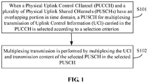
FIG. 1 is a flow diagram of a method for multiplexing transmission of information as shown in an exemplary embodiment of the disclosure. The embodiment is described from a User Equipment (UE) side. As shown inFIG. 1 , the method for multiplexing transmission of information includes the following operations. - In operation S101, when a Physical Uplink Control Channel (PUCCH) and a plurality of Physical Uplink Shared Channels (PUSCHs) have an overlapping portion in time-domain, a PUSCH for multiplexing transmission of Uplink Control Information (UCI) carried in the PUCCH is selected based on a selection criterion.
- Optionally, the method may further include: a selection criterion sent by a base station is received, and the selection criterion may also be agreed with a base station.
- The selecting the PUSCH for the multiplexing transmission of the UCI carried in the PUCCH based on the selection criterion may include, but is not limited to, any of the following situations.
- Scenario 1): a PUSCH with an earliest starting position or an earliest ending position in time-domain is taken as the PUSCH for the multiplexing transmission of the UCI.
- For example, as shown in
FIG. 2A , it is assumed that PUCCH1 inFIG 2A carries UCI1, PUCCH2 carries UCI2, PUSCH1 carriesdata 1, and PUSCH2 carriesdata 2. Since a starting position of PUSCH1 in time-domain is earlier than that of PUSCH2, PUSCH1 is selected as the PUSCH for the multiplexing transmission of the UCI. Both the UCI of PUCCH1 and PUCCH2 are multiplexed in the PUSCH1. As shown inFIG. 2B , UCI1, UCI2 anddata 1 may be transmitted by multiplexing in the PUSCH1. - Scenario 2): when one PUSCH of the plurality of PUSCHs for uplink transmission is based on the DL grant and another PUSCH for uplink transmission is based on configured grant, a PUSCH for uplink transmission based on downlink dynamic scheduling (DL grant) is taken as the PUSCH for the multiplexing transmission of the UCI.
- For example, as shown in
FIG. 3A , it is assumed that PUCCH1 inFIG 3A carries UCI1, PUCCH2 carries UCI2, PUSCH1 carriesdata 1, and PUSCH2 carriesdata 2, PUSCH1 is a PUSCH for uplink transmission based on DL grant, PUSCH2 is a PUSCH for uplink transmission based on configured grant. Thus, PUSCH1 may be selected as the PUSCH for the multiplexing transmission of the UCI. Both PUCCH1 and PUCCH2 may conduct multiplexing transmission of the UCI through PUSCH1. As shown inFIG. 3B , multiplexing transmission of UCI1, UCI2 anddata 1 may be conducted through PUSCH1. - Scenario 3): a PUSCH with the maximum number of symbols in time-domain overlapped with the PUCCH is selected as the PUSCH for the multiplexing transmission of the UCI.
- For example, as shown in
FIG. 4A , it is assumed that PUCCH1 inFIG 4A carries UCI1, PUCCH2 carries UCI2, PUSCH1 carriesdata 1, and PUSCH2 carriesdata 2. The number of overlapped symbols in time-domain of PUCCH1 and PUSCH1 is relatively large, therefore, UCI1 anddata 1 are transmitted by multiplexing in PUSCH1. The number of overlapped symbols in time-domain of PUCCH2 and PUSCH2 is relatively large, thus UCI2 anddata 2 are transmitted by multiplexing in PUSCH2. As shown inFIG. 4B , UCI1 anddata 1 may be transmitted by multiplexing in PUSCH1, and UCI2 anddata 2 may be transmitted by multiplexing in PUSCH2. - Scenario 4): a PUSCH with the maximum number of occupied resource units in a time-frequency resource is selected as the PUSCH for the multiplexing transmission of the UCI.
- For example, as shown in
FIG. 5A , it is assumed that PUCCH1 inFIG 5A carries UCI1, PUCCH2 carries UCI2, PUSCH1 carriesdata 1, and PUSCH2 carriesdata 2. Since the number of the resource units in time-domain resource occupied by PUSCH1 is relatively large, PUSCH1 is selected as the PUSCH for the multiplexing transmission of the UCI. As shown inFIG. 5B , UCI1, UCI2 anddata 1 may be transmitted by multiplexing in PUSCH1. - Scenario 5): a corresponding selection criterion is determined according to a type of the UCI and pre-stored corresponding relationships between types of UCI and different selection criteria. A PUSCH is selected as the PUSCH for the multiplexing transmission of the UCI according to the determined selection criterion.
- Optionally, the method may further include: the corresponding relationships between types of the UCI and the different selection criteria sent by a base station are received, or the corresponding relationships between types of the UCI and the different selection criteria may be agreed with a base station.
- For example, as shown in
FIG. 6A , as for feedback information which is HARQ Acknowledgement (HARQ-ACK), the PUSCH, namely PUSCH2, with the earliest starting position in time-domain may be selected for the multiplexing transmission. While as for a report message that is a channel Status Indicator (CSI), the PUSCH, namely PUSCH1, with the maximum number of occupied resource units in the time-frequency resource may be selected as the PUSCH for the multiplexing transmission. As shown inFIG. 6B , HARQ anddata 2 may be transmitted by multiplexing in PUSCH2, and CSI anddata 1 may be transmitted by multiplexing in PUSCH1. - In operation S102, multiplexing transmission is performed by multiplexing the UCI and transmission content of the selected PUSCH in the selected PUSCH.
- In the embodiment, after the selected PUSCH is determined, the multiplexing transmission may be performed by multiplexing the UCI and the transmission content of the selected PUSCH in the selected PUSCH.
- According to the above embodiments, when a PUCCH and a plurality of PUSCHs have an overlapping portion in time-domain, a PUSCH for multiplexing transmission of UCI carried in the PUCCH may be selected based on a selection criterion. The selected PUSCH may be used for performing the transmission by multiplexing the UCI and the transmission content of the selected PUSCH in the selected PUSCH, and thereby a suitable PUSCH is selected for the multiplexing transmission.
-
FIG. 7 is a flow diagram of a method for receiving information as shown in an exemplary embodiment of the disclosure. The embodiment is described from a base station side. As shown inFIG. 7 , the method includes the operations as below. - In operation S701, a plurality of PUSCH transmissions are received.
- In operation S702, a PUSCH for multiplexing transmission of UCI is determined based on a selection criterion.
- Optionally, the method may further include: a selection criterion is determined and sent to UE, or the selection criterion can also be agreed with the UE.
- In the embodiment, after the selection criterion is determined or agreed, the PUSCH for the multiplexing transmission of the UCI can be determined based on the selection criterion.
- In operation S703, the UCI is received from the determined PUSCH.
- According to the above embodiment, by receiving a plurality of PUSCH transmissions, a PUSCH for multiplexing transmission of UCI may be determined based on a selection criterion, and the UCI may be received from the determined PUSCH, thereby receiving the UCI.
-
FIG. 8 is a signaling flow diagram of the method for receiving information as shown in an exemplary embodiment of the disclosure. The embodiment is described from the angle of interaction between a base station and UE. As shown inFIG. 8 , the method includes following operations. - In operation S801, the base station determines a selection criterion and sends the selection criterion to the UE.
- In operation S802, the UE receives the selection criterion.
- In operation S803, when a PUCCH and a plurality of PUSCHs have an overlapping portion in time-domain, the UE selects a PUSCH for multiplexing transmission of UCI carried in the PUCCH according to the received selection criterion.
- In operation S804, the UE performs the transmission by multiplexing the UCI and transmission content of the selected PUSCH in the selected PUSCH.
- In operation S805, the base station receives the plurality of PUSCH transmissions.
- In operation S806, the base station determines the PUSCH for the multiplexing transmission of the UCI according to the determined selection criterion.
- In operation S807, the base station receives the UCI from the determined PUSCH.
- According to the above embodiment, through the interaction between the base station and the UE, the UE can select a suitable PUSCH for the multiplexing transmission, and thus the base station can determine the PUSCH for the multiplexing transmission of UCI and receives the UCI from the determined PUSCH.
-
FIG. 9 is a block diagram of an apparatus for multiplexing transmission of information as shown in an exemplary embodiment of the disclosure. The apparatus is arranged in UE. As shown inFIG. 9 , the apparatus includes aselection module 91 and atransmission module 92. - The
selection module 91 is configured to select a PUSCH for multiplexing transmission of UCI carried in a PUCCH based on a selection criterion when the PUCCH and a plurality of PUSCHs have an overlapping portion in time-domain. - The
transmission module 92 is configured to perform the transmission by multiplexing the UCI and transmission content of the selected PUSCH in the PUSCH selected by theselection module 91. - In the embodiment, after the selected PUSCH is determined, the transmission may be performed by multiplexing the UCI and the transmission content of the selected PUSCH in the selected PUSCH.
- According to the above embodiment, when a PUCCH and a plurality of PUSCHs have an overlapping portion in the time-domain, a PUSCH for multiplexing transmission of UCI carried in the PUCCH may be selected based on a selection criterion, and the transmission may be performed by multiplexing the UCI and the transmission content of the selected PUSCH in the selected PUSCH.
-
FIG. 10 is a block diagram of another apparatus for multiplexing transmission of information as shown in an exemplary embodiment of the disclosure. As shown inFIG. 10 , on the basis of the embodiment shown inFIG. 9 above, theselection module 91 may include: afirst selection submodule 911. - The
first selection submodule 911 is configured to take a PUSCH with an earliest starting position or an earliest ending position in time-domain as the PUSCH for the multiplexing transmission of the UCI. - For example, as shown in
Fig 2A , it is assumed that PUCCH1 inFIG. 2A carries UCI1, PUCCH2 carries UCI2, PUSCH1 carriesdata 1, and PUSCH2 carriesdata 2. Since a starting position of PUSCH1 in the time-domain is earlier than that of PUSCH2, PUSCH1 may be selected as the PUSCH for the multiplexing transmission of the UCI. Both the UCI of PUCCH1 and PUCCH2 are multiplexed in the PUSCH1. As shown inFIG. 2B , UCI1, UCI2 anddata 1 may be transmitted by multiplexing in the PUSCH1. - According to the above embodiment, a PUSCH with an earliest starting position or an earliest ending position in time-domain is adopted as the PUSCH for the multiplexing transmission of the UCI, which provides a condition for subsequent multiplexing transmission of the UCI in the selected PUSCH. The implementation is simple.
-
FIG. 11 is a block diagram of yet another apparatus for multiplexing transmission of information as shown in an exemplary embodiment of the disclosure. As shown inFIG. 11 , on the basis of the embodiment shown inFIG. 9 above, theselection module 91 may include asecond selection submodule 912. - The
second selection submodule 912 is configured to take a PUSCH for uplink transmission based on DL grant as the PUSCH for the multiplexing transmission of the UCI when a PUSCH of the plurality of PUSCHs is a PUSCH for uplink transmission based on the DL grant and a PUSCH of the plurality of PUSCHs is a PUSCH for uplink transmission based on configured grant. - According to the above embodiment, a PUSCH for uplink transmission based on DL grant is adopted as the PUSCH for multiplexing transmission of UCI, which provides a condition for subsequent multiplexing transmission of the UCI in the selected PUSCH. Such implementation is simple.
-
FIG. 12 is a block diagram of yet another apparatus for multiplexing transmission of information as shown in an exemplary embodiment of the disclosure. As shown inFIG. 12 , on the basis of the embodiment shown inFIG. 9 above, theselection module 91 may include athird selection submodule 913. - The
third selection submodule 913 is configured to select a PUSCH with the maximum number of symbols in time-domain overlapped with the PUCCH as the PUSCH for the multiplexing transmission of the UCI. - According to the above embodiment, a PUSCH with the maximum number of symbols in time-domain overlapped with the PUCCH is selected as the PUSCH for multiplexing transmission of UCI, which provides a condition for subsequent multiplexing transmission of the UCI in the selected PUSCH, The implementation is simple.
-
FIG. 13 is a block diagram of yet another apparatus for multiplexing transmission of information as shown in an exemplary embodiment of the disclosure. As shown inFIG. 13 , on the basis of the embodiment of theFIG. 9 above, theselection module 91 may include afourth selection submodule 914. - The
fourth selection submodule 914 is configured to select a PUSCH with the maximum number of resource units in an occupied time-frequency resource as the PUSCH for the multiplexing transmission of the UCI. - According to the above embodiment, a PUSCH with the maximum number of resource units in the occupied time-frequency resource is selected as the PUSCH for multiplexing transmission of UCI, which provides a condition for subsequent multiplexing transmission of the UCI in the selected PUSCH, The implementation is simple.
-
FIG. 14 is a block diagram of yet another apparatus for multiplexing transmission of information as shown in an exemplary embodiment of the disclosure. As shown inFIG. 14 , on the basis of the embodiment shown inFIG. 9 above, theselection module 91 may include a determiningsubmodule 915 and afifth selection submodule 916. - The determining
submodule 915 is configured to determine a corresponding selection criterion according to a type of the UCI and pre-stored corresponding relationships between types of UCI and different selection criteria; and - The fifth determining
submodule 916 is configured to select a PUSCH as the PUSCH for the multiplexing transmission of the UCI based on the selection criterion determined by the determiningsubmodule 915. - According to the above embodiment, a PUSCH may be selected as the PUSCH for multiplexing transmission of UCI according to a determined selection criterion, which provides a condition for subsequent multiplexing transmission of the UCI in the selected PUSCH, The an implementation is simple.
-
FIG. 15 is a block diagram of yet another apparatus for multiplexing transmission of information as shown in an exemplary embodiment of the disclosure. As shown inFIG. 15 , on the basis of the embodiment shown inFIG. 9 above, the apparatus may further include a receivingmodule 93 or an agreeingmodule 94. - The receiving
module 93 is configured to receive the selection criterion or the corresponding relationships between types of UCI and different selection criteria from a base station. - The agreeing
module 94 is configured to agree the selection criterion or the corresponding relationships between types of UCI and different selection criteria with the base station. - According to the above embodiment, the selection criterion may be determined or agreed, which provides a condition for subsequent selection of the PUSCH for the multiplexing transmission of the UCI based on the selection criterion.
-
FIG. 16 is a block diagram of an apparatus for receiving information as shown in an exemplary embodiment of the disclosure. The apparatus can be located in a base station. As shown inFIG. 16 , the apparatus includes: - a
first receiving module 161, configured to receive of a plurality of PUSCH transmissions; - a determining
module 162, configured to determine a PUSCH for multiplexing transmission of UCI from the plurality of PUSCHs received by thefirst receiving module 161 based on a selection criterion; and - a
second receiving module 163, configured to receive the UCI from the PUSCH determined by the determining module. - According to the above embodiment, upon receiving a plurality of PUSCH transmissions, a PUSCH for multiplexing transmission of UCI may be determined based on a selection criterion, and the UCI may be received from the determined PUSCH, thereby receiving the UCI.
-
FIG. 17 is a block diagram of another apparatus for receiving information as shown in an exemplary embodiment of the disclosure. As shown inFIG. 17 , on the basis of the embodiment shown inFIG. 16 above, the apparatus may further include a first determining and sendingmodule 164, a second determining and sendingmodule 165 or an agreeingmodule 166. - The first determining and sending
module 164 is configured to determine the selection criterion and send the selection criterion to UE. - The second determining and sending
module 165 is configured to determine corresponding relationships between the type of the UCI and different selection criteria and send the corresponding relationships between types of UCI and different selection criteria to the UE. - The agreeing
module 166 is configured to agree the selection criterion or the corresponding relationships between types of UCI and different selection criteria with the UE. - According to the above embodiment, a selection criterion may be determined and sent to UE or may be agreed with the UE, which enables the UE to select a PUSCH for multiplexing transmission of UCI based on the selection criterion.
-
FIG. 18 is a block diagram of an apparatus suitable for multiplexing transmission of information as shown in an exemplary embodiment of the disclosure. For example, theapparatus 1800 may be user equipment such as a mobile phone, a computer, a digital broadcasting terminal, a message transceiver, a game console, tablet equipment, medical equipment, fitness equipment, and a personal digital assistant. - Referring to
FIG. 18 , theapparatus 1800 may include one or more of the following components: aprocessing component 1802, amemory 1804, apower component 1806, amultimedia component 1808, anaudio component 1810, an Input/Output (I/O)interface 1812, asensor component 1814, and acommunication component 1816. - The
processing component 1802 generally controls overall operations of theapparatus 1800, such as operations related to displaying, telephone calls, data communications, camera operations, and recording operations. Theprocessing component 1802 may include one ormore processors 1820 to execute instructions, so as to complete all or part of the operations of the method described above. In addition, theprocessing component 1802 may include one or more modules to facilitate the interaction between theprocessing component 1802 and other components. For example, theprocessing component 1802 may include a multimedia module to facilitate the interaction between themultimedia component 1808 and theprocessing component 1802. - One of the
processors 1820 of theprocessing component 1802 may be configured to: - select a PUSCH for multiplexing transmission of UCI carried in a PUCCH based on a selection criterion when the PUCCH and a plurality of PUSCHs have an overlapping portion in time-domain; and
- perform multiplexing transmission by multiplexing the UCI and transmission content of the selected PUSCH in the selected PUSCH.
- The
memory 1804 is configured to store various types of data to support the operation of theapparatus 1800. Examples of such data include instructions for any application program or method operated on theapparatus 1800, contact data, phone book data, messages, pictures, videos, and the like. Thememory 1804 may be implemented by any type of volatile or non-volatile storage devices or a combination thereof, such as a Static Random Access Memory (SRAM), an Electrically Erasable Programmable Read-Only Memory (EEPROM), a Programming Read-Only Memory (EPROM), a Programmable Read-Only Memory (PROM), a Read-Only Memory (ROM), a magnetic memory, a flash memory, a magnetic disk or an optical disk. - The
power component 1806 is configured to provide power for various components of theapparatus 1800. Thepower component 1806 may include a power management system, one or more power supplies, and other components associated with generating, managing, and distributing power for theapparatus 1800. - The
multimedia component 1808 may include a screen providing an output interface between theapparatus 1800 and a user. In some embodiments, the screen may include an LCD and a TP. If it includes the TP, the screen may be implemented as a touch screen to receive an input signal from a user. The TP includes one or more touch sensors to sense touch, swipe, and gestures on the TP. The touch sensors may not only sense a boundary of a touch or swipe action, but also detect a time of duration and a pressure associated with the touch or swipe action. In some embodiments, themultimedia component 1808 includes a front camera and/or a rear camera. The front camera and the rear camera may receive external multimedia data while theapparatus 1800 is in an operation mode, such as a photographing mode or a video mode. Each of the front camera and rear camera may be a fixed optical lens system or may have focal lengths and optical zoom capabilities. - The
audio component 1810 is configured to output and/or input audio signals. For example, theaudio component 1810 includes a microphone (MIC), and the microphone is configured to receive an external audio signal when theapparatus 1800 is in an operation mode, such as a calling mode, a recording mode, and a voice identification mode. The received audio signals may be further stored in thememory 1804 or transmitted via thecommunication component 1816. In some embodiments, theaudio component 1810 may further include a speaker to output audio signals. - The I/
O interface 1812 is configured to provide an interface between theprocessing component 1802 and peripheral interface modules, which may be keyboards, click wheels, buttons, etc. These buttons may include, but are not limited to: a home button, a volume button, a start button, and a lock button. - The
sensor component 1814 may include one or more sensors configured to provide various aspects of state assessment for theapparatus 1800. For example, thesensor component 1814 may detect an on/off status of theapparatus 1800, and relative positioning of components. For example, the component is a display and a keypad of theapparatus 1800. Thesensor component 1814 may also detect a change in position of theapparatus 1800 or a component of theapparatus 1800, presence or absence of user contact with theapparatus 1800, an orientation or an acceleration/deceleration of theapparatus 1800, and a change in temperature of theapparatus 1800. Thesensor component 1814 may include a proximity sensor configured to detect the presence of objects nearby without any physical contact. Thesensor component 1814 may also include light sensors, such as CMOS or CCD image sensors, for use in imaging applications. In some embodiments, thesensor component 1814 may also include an acceleration sensor, a gyroscope sensor, a magnetic sensor, a pressure sensor, or a temperature sensor. - The
communication component 1816 is configured to facilitate wired or wireless communications between theapparatus 1800 and other devices. Theapparatus 1800 may access a wireless network based on a communication standard, such as WiFi, 2G or 6G, or a combination thereof. In an exemplary embodiment, thecommunication component 1816 receives a broadcast signal or broadcast related information from an external broadcast management system via a broadcast channel. In one exemplary embodiment, thecommunication component 1816 further includes a Near Field Communication (NFC) module to promote short-range communications. For example, the NFC module may be implemented based on a Radio Frequency Identification (RFID) technology, an Infrared Data Association (IrDA), an Ultra-Wide Band (UWB) technology, a Bluetooth (BT) technology and other technologies. - In the exemplary embodiment, the
apparatus 1800 may be implemented by one or more Application-Specific Integrated Circuits (ASICs), Digital Signal Processors (DSPs), Digital Signal Processing Devices (DSPDs), Programmable Logic Devices (PLDs), Field Programmable Gate Arrays (FPGAs), controllers, microcontrollers, microprocessors, or other electronic components to perform the above method. - In the exemplary embodiment, a non-transitory computer-readable storage medium storing instructions, such as the
memory 1804 storing instructions, is further provided. The above instructions may be executed by theprocessor 1820 of theapparatus 1800 to complete the foregoing method. For example, the non-transitory computer-readable storage medium may be a Read Only Memory (ROM), a Random Access Memory (RAM), a CD-ROM, a magnetic tape, a floppy disc, an optical data storage device, and the like. -
FIG. 19 is a block diagram illustrating an apparatus suitable for multiplexing transmission of information according to an exemplary embodiment. Theapparatus 1900 may be provided as a base station. Referring toFIG. 19 , theapparatus 1900 includes aprocessing component 1922, a wireless transmitting/receiving component 1924, anantenna component 1926 and a specific signal processing part of a wireless interface. Theprocessing component 1922 may further include one or more processors. - One of the processors in the
processing component 1922 may be configured to: - receive a plurality of PUSCH transmissions;
- determine a PUSCH for multiplexing transmission of UCI based on a selection criterion; and
- receive the UCI from the determined PUSCH.
- In the exemplary embodiment, a non-transitory computer-readable storage medium storing instructions is further provided. The above instructions may be executed by the
processing component 1922 of theapparatus 1900 to implement the above method for receiving information. For example, the non-transitory computer-readable storage medium may be a Read Only Memory (ROM), a Random Access Memory (RAM), a CD-ROM, a magnetic tape, a floppy disc, an optical data storage device, and the like. - For the apparatus embodiments, reference will now be made in part to the description of the method embodiments since the apparatus embodiments substantially correspond to the method embodiments. The apparatus embodiments described above are merely illustrative. The units illustrated as separate elements may or may not be physically separate. The elements shown as units may or may not be physical units, i.e., may be arranged in one place, or may be distributed in a plurality of network units. Some or all of the modules may be selected according to actual needs to achieve the solutions of the embodiments. Those ordinarily skilled in the art would understand and practice without involving any inventive effort.
- It should be noted that in the disclosure, relational terms such as "first", "second" and the like are used only to distinguish one entity or operation from another entity or operation without necessarily requiring or implying any such actual relationship or order between such entities or operations. The terms "includes", "including" or any other variations thereof are intended to cover a non-exclusive inclusion, such that a process, method, article, or equipment that includes a list of elements not only includes those elements but also may include other elements not expressly listed or inherent to such process, method, article, or equipment. Under the condition of no more limitations, an element defined by statement "including a/an......" does not exclude existence of another element that is the same in a process, method, object or device including the element.
- Other embodiments of the disclosure will readily occur to those skilled in the art upon consideration of the specification and practice of the disclosure disclosed herein. The application is intended to cover any variation, use or adaptation of the disclosure, which follows the general principles of the disclosure and includes common knowledge or conventional technical means in the technical field not disclosed in the disclosure. The specification and the embodiments are considered as being exemplary only, with a true scope and spirit of the disclosure being indicated by the following claims.
- It should be understood that the disclosure is not limited to the exact construction that has been described above and illustrated in the accompanying drawings, and that various modifications and changes can be made without departing from the scope thereof. The scope of the disclosure is limited only by the appended claims.
Claims (22)
- A method for multiplexing transmission of information, applicable to User Equipment (UE), the method comprising:selecting a PUSCH for multiplexing transmission of Uplink Control Information (UCI) carried in the PUCCH based on a selection criterion when a Physical Uplink Control Channel (PUCCH) and a plurality of Physical Uplink Shared Channels (PUSCHs) have an overlapping portion in time-domain; andperforming multiplexing transmission by multiplexing the UCI and transmission content of the selected PUSCH in the selected PUSCH.
- The method according to claim 1, wherein the selecting the PUSCH for the multiplexing transmission of the UCI carried in the PUCCH based on the selection criterion comprises:
taking a PUSCH with an earliest starting position or an earliest ending position in time-domain as the PUSCH for the multiplexing transmission of the UCI. - The method according to claim 1, wherein the selecting the PUSCH for the multiplexing transmission of the UCI carried in the PUCCH based on the selection criterion comprises:
when a PUSCH of the plurality of PUSCHs is a PUSCH for uplink transmission based on a downlink dynamic scheduling (DL grant) and a PUSCH of the plurality of PUSCHs is a PUSCH for uplink transmission based on configured grant, taking the PUSCH for uplink transmission based on the DL grant as the PUSCH for the multiplexing transmission of the UCI. - The method according to claim 1, wherein the selecting the PUSCH for the multiplexing transmission of the UCI carried in the PUCCH based on the selection criterion comprises:
selecting a PUSCH with a maximum number of symbols in time-domain overlapped with the PUCCH as the PUSCH for the multiplexing transmission of the UCI. - The method according to claim 1, wherein the selecting the PUSCH for the multiplexing transmission of the UCI carried in the PUCCH based on the selection criterion comprises:
selecting a PUSCH with a maximum number of resource units in an occupied time-frequency resource as the PUSCH for the multiplexing transmission of the UCI. - The method according to claim 1, wherein the selecting the PUSCH for the multiplexing transmission of the UCI carried in the PUCCH based on the selection criterion comprises:determining the selection criterion a type of the UCI and pre-stored corresponding relationships between types of UCI and different selection criteria; andselecting a PUSCH as the PUSCH for the multiplexing transmission of the UCI according to the determined selection criterion.
- The method according to any one of claims 1-6, further comprising:receiving the selection criterion or the corresponding relationships between types of UCI and different selection criteria from a base station; oragreeing the selection criterion or the corresponding relationships between types of UCI and different selection criteria with a base station.
- A method for receiving information, applicable to a base station, the method comprising:receiving a plurality of Physical Uplink Shared Channel (PUSCH) transmissions;determining a PUSCH for multiplexing transmission of Uplink Control Information (UCI) based on a selection criterion; andreceiving the UCI from the determined PUSCH.
- The method according to claim 8, further comprising:determining the selection criterion and sending the selection criterion to User Equipment (UE); ordetermining corresponding relationships between types of UCI and different selection criteria and sending the corresponding relationships between types of UCI and different selection criteria to UE; oragreeing the selection criterion or corresponding relationships between types of UCI and different selection criteria with UE.
- An apparatus for multiplexing transmission of information, applicable to User Equipment (UE), the apparatus comprising:a selection module, configured to select a Physical Uplink Shared Channel (PUSCH) for multiplexing transmission of Uplink Control Information (UCI) carried in a Physical Uplink Control Channel (PUCCH) based on a selection criterion when the PUCCH and a plurality of PUSCHs have an overlapping portion in time-domain; anda transmission module, configured to perform multiplexing transmission by multiplexing the UCI and transmission content of the selected PUSCH in the selected PUSCH.
- The apparatus according to claim 10, wherein the selection module comprises:
a first selection submodule, configured to take a PUSCH with an earliest starting position or an earliest ending position in time-domain as the PUSCH for the multiplexing transmission of the UCI. - The apparatus according to claim 10, wherein the selection module comprises:
a second selection submodule, configured to, when a PUSCH of the plurality of PUSCHs is a PUSCH for uplink transmission based on a downlink dynamic scheduling (DL grant) and a PUSCH of the plurality of PUSCHs is a PUSCH for uplink transmission based on configured grant, take the PUSCH for uplink transmission based on the DL grant as the PUSCH for the multiplexing transmission of the UCI. - The apparatus according to claim 10, wherein the selection module comprises:
a third selection submodule, configured to select a PUSCH with a maximum number of symbols in time-domain overlapped with the PUCCH as the PUSCH for the multiplexing transmission of the UCI. - The apparatus according to claim 10, wherein the selection module comprises:
a fourth selection submodule, configured to select a PUSCH with a maximum number of resource units in an occupied time-frequency resource as the PUSCH for the multiplexing transmission of the UCI. - The apparatus according to claim 10, wherein the selection module comprises:a determining submodule, configured to determine the selection criterion according to a type of the UCI and pre-stored corresponding relationships between types of UCI and different selection criteria; anda fifth selection submodule, configured to select a PUSCH as the PUSCH for the multiplexing transmission of the UCI based on the selection criterion determined by the determining submodule.
- The apparatus according to any one of claims 10-15, further comprising:a receiving module, configured to receive the selection criterion or the corresponding relationships between types of UCI and different selection criteria from a base station; oran agreeing module, configured to agree the selection criterion or the corresponding relationships between types of UCI and different selection criteria with a base station.
- An apparatus for receiving information, applicable to a base station, the apparatus comprising:a first receiving module, configured to receive a plurality of Physical Uplink Shared Channel (PUSCH) transmissions;a determining module, configured to determine a PUSCH for multiplexing transmission of Uplink Control Information (UCI) from the plurality of PUSCHs received by the first receiving module based on a selection criterion; anda second receiving module, configured to receive the UCI from the PUSCH determined by the determining module.
- The apparatus according to claim 17, further comprising:a first determining and sending module, configured to determine the selection criterion and send the selection criterion to User Equipment (UE); ora second determining and sending module, configured to determine corresponding relationships between types of UCI and different selection criteria and send the corresponding relationships between types of UCI and different selection criteria to UE; oran agreeing module, configured to agree the selection criterion or corresponding relationships between types of UCI and different selection criteria with UE.
- User Equipment (UE), comprising:a processor; anda memory, configured to store instructions executable by the processor;wherein the processor is configured to:select a Physical Uplink Shared Channel (PUSCH) for multiplexing transmission of Uplink Control Information (UCI) carried in a Physical Uplink Control Channel (PUCCH) based on a selection criterion when the PUCCH and a plurality of PUSCHs have an overlapping portion in time-domain; andperform multiplexing transmission by multiplexing the UCI and transmission content of the selected PUSCH in the selected PUSCH.
- A base station, comprising:a processor; anda memory, configured to store instructions executable by the processor;wherein the processor is configured to:receive a plurality of Physical Uplink Shared Channel (PUSCH) transmissions;determine a PUSCH for multiplexing transmission of Uplink Control Information (UCI) based on a selection criterion; andreceive the UCI from the determined PUSCH.
- A computer-readable storage medium, storing computer instructions thereon that, when executed by a processor, implement operations of the method for multiplexing transmission of information according to any one of claims 1-7.
- A computer-readable storage medium, storing computer instructions thereon that, when executed by a processor, implement operations of the method for receiving information according to claim 8 or 9.
Applications Claiming Priority (1)
| Application Number | Priority Date | Filing Date | Title |
|---|---|---|---|
| PCT/CN2018/086357 WO2019213907A1 (en) | 2018-05-10 | 2018-05-10 | Information multiplexing transmission method and apparatus, and information receiving method and apparatus |
Publications (3)
| Publication Number | Publication Date |
|---|---|
| EP3790334A1 true EP3790334A1 (en) | 2021-03-10 |
| EP3790334A4 EP3790334A4 (en) | 2021-05-05 |
| EP3790334B1 EP3790334B1 (en) | 2023-10-18 |
Family
ID=63841448
Family Applications (1)
| Application Number | Title | Priority Date | Filing Date |
|---|---|---|---|
| EP18918339.5A Active EP3790334B1 (en) | 2018-05-10 | 2018-05-10 | Information multiplexing transmission method and apparatus, and information receiving method and apparatus |
Country Status (11)
| Country | Link |
|---|---|
| US (1) | US20210144702A1 (en) |
| EP (1) | EP3790334B1 (en) |
| JP (2) | JP7328994B2 (en) |
| KR (2) | KR102565624B1 (en) |
| CN (2) | CN113055134B (en) |
| BR (1) | BR112020022606A2 (en) |
| ES (1) | ES2964135T3 (en) |
| PL (1) | PL3790334T3 (en) |
| RU (1) | RU2752253C1 (en) |
| SG (1) | SG11202011067VA (en) |
| WO (1) | WO2019213907A1 (en) |
Cited By (1)
| Publication number | Priority date | Publication date | Assignee | Title |
|---|---|---|---|---|
| WO2021155502A1 (en) | 2020-02-05 | 2021-08-12 | Qualcomm Incorporated | Uci multiplexing on pusch for multi-panel uplink transmission |
Families Citing this family (27)
| Publication number | Priority date | Publication date | Assignee | Title |
|---|---|---|---|---|
| CN108271264B (en) * | 2017-01-03 | 2020-06-30 | 上海朗帛通信技术有限公司 | Method and device used in UE (user equipment) and base station for multi-antenna transmission |
| CN110505698B (en) * | 2018-05-18 | 2023-06-23 | 中兴通讯股份有限公司 | Channel configuration method, terminal, storage medium and electronic device |
| CN110650535B (en) * | 2018-06-26 | 2023-01-06 | 中国信息通信研究院 | Method and device for multiplexing and sending uplink signals of unlicensed frequency band |
| CN110808819B (en) * | 2018-08-06 | 2021-03-30 | 华为技术有限公司 | Information transmission method and device |
| US20210345390A1 (en) * | 2018-08-09 | 2021-11-04 | Ntt Docomo, Inc. | User terminal and radio communication method |
| JP7309335B2 (en) * | 2018-09-19 | 2023-07-18 | シャープ株式会社 | TERMINAL DEVICE, BASE STATION DEVICE, AND COMMUNICATION METHOD |
| CN111049627B (en) * | 2018-10-12 | 2022-05-31 | 上海朗帛通信技术有限公司 | Method and device used in user equipment and base station for wireless communication |
| CN111435878B (en) * | 2019-01-11 | 2021-10-01 | 大唐移动通信设备有限公司 | Information transmission method, terminal and network equipment |
| CN111464259B (en) * | 2019-01-18 | 2021-10-29 | 上海朗帛通信技术有限公司 | Method and device used in user equipment and base station for wireless communication |
| CN111757514B (en) * | 2019-03-29 | 2023-04-07 | 大唐移动通信设备有限公司 | Processing method, indication method, terminal and network side equipment of hybrid automatic repeat request (HARQ) mechanism |
| CN111865510B (en) * | 2019-04-30 | 2021-11-23 | 大唐移动通信设备有限公司 | HARQ-ACK transmission method, user equipment and network side equipment |
| CN111953456B (en) * | 2019-05-14 | 2021-10-29 | 大唐移动通信设备有限公司 | Signaling transmission method, user terminal, base station and storage medium |
| CN111835480B (en) * | 2019-07-05 | 2021-11-19 | 维沃移动通信有限公司 | UCI transmission method, UCI receiving method, terminal and network equipment |
| CN111800240B (en) * | 2019-07-30 | 2022-01-14 | 维沃移动通信有限公司 | Information transmission method, device, terminal, equipment and medium |
| CN111835481B (en) * | 2019-08-02 | 2023-07-25 | 维沃移动通信有限公司 | Uplink transmission method, terminal and network equipment |
| WO2021031031A1 (en) * | 2019-08-16 | 2021-02-25 | 华为技术有限公司 | Method and apparatus for determining channel |
| WO2021093892A1 (en) * | 2019-11-17 | 2021-05-20 | Guangdong Oppo Mobile Telecommunications Corp., Ltd. | Apparatus and method of wireless communication |
| US20210219331A1 (en) * | 2020-01-15 | 2021-07-15 | Qualcomm Incorporated | Feedback transmissions based on uplink grants |
| CN113452482B (en) * | 2020-03-27 | 2023-05-02 | 大唐移动通信设备有限公司 | Information transmission method, device, equipment and computer readable storage medium |
| CN111601388A (en) * | 2020-05-15 | 2020-08-28 | 捷开通讯(深圳)有限公司 | Uplink transmission method based on carrier aggregation, storage medium and user equipment |
| WO2021226991A1 (en) * | 2020-05-15 | 2021-11-18 | Qualcomm Incorporated | Uplink downlink control information for scheduling multiple component carriers |
| CN113939023A (en) * | 2020-07-13 | 2022-01-14 | 维沃移动通信有限公司 | Conflict processing method and device |
| CN113965998A (en) * | 2020-07-21 | 2022-01-21 | 维沃移动通信有限公司 | Uplink transmission method, device and related equipment |
| CN114071571A (en) * | 2020-08-07 | 2022-02-18 | 大唐移动通信设备有限公司 | Transmission method, device and storage medium for uplink channel conflict |
| WO2023050105A1 (en) * | 2021-09-28 | 2023-04-06 | Huizhou Tcl Cloud Internet Corporation Technology Co., Ltd | Wireless communication method, user equipment, and base station |
| CN116489790A (en) * | 2022-01-11 | 2023-07-25 | 大唐移动通信设备有限公司 | UCI transmission method, terminal, network equipment, device and storage medium |
| WO2023155377A1 (en) * | 2022-02-18 | 2023-08-24 | Oppo广东移动通信有限公司 | Wireless communication method and apparatus, device, storage medium and program product |
Family Cites Families (24)
| Publication number | Priority date | Publication date | Assignee | Title |
|---|---|---|---|---|
| KR20100083440A (en) * | 2009-01-13 | 2010-07-22 | 삼성전자주식회사 | Apparatus and method for transmission of physical uplink control signaling in uplink wireless communication systems with multi-carrier transmission |
| CN101695017A (en) * | 2009-10-27 | 2010-04-14 | 中兴通讯股份有限公司 | Method and device for transmitting an uplink control signaling on a physical uplink shared channel |
| CN103152091B (en) * | 2010-01-08 | 2015-11-25 | 华为技术有限公司 | Signaling method, equipment and system |
| JP5216058B2 (en) * | 2010-02-15 | 2013-06-19 | 株式会社エヌ・ティ・ティ・ドコモ | Mobile terminal apparatus and uplink control information signal transmission method |
| CN101932116B (en) * | 2010-08-09 | 2015-08-12 | 中兴通讯股份有限公司 | A kind of method and subscriber equipment selecting Physical Uplink Shared Channel |
| US20120044889A1 (en) * | 2010-08-19 | 2012-02-23 | Yu-Chih Jen | Method of Handling Uplink Control Information Reporting and Related Communication Device |
| EP2938146A4 (en) * | 2012-12-19 | 2015-12-30 | Fujitsu Ltd | Radio communication apparatus and radio communication method |
| CN104904174B (en) * | 2013-01-09 | 2018-01-23 | Lg电子株式会社 | Send the method and its equipment of signal |
| HUE047100T2 (en) * | 2013-12-03 | 2020-04-28 | Lg Electronics Inc | Methods and apparatuses for transmitting uplink in wireless access system supporting machine-type communication |
| US10355843B2 (en) * | 2015-01-22 | 2019-07-16 | Lg Electronics Inc. | Carrier aggregation method performed by terminal in wireless communication system and terminal using same method |
| US10009920B2 (en) * | 2015-01-27 | 2018-06-26 | Qualcomm Incorporated | Triggering a group acknowledgement/negative acknowledgement or channel state information |
| US20160277155A1 (en) * | 2015-03-17 | 2016-09-22 | Nokia Technologies Oy | Efficient resource allocation for acknowledgement/non-acknowledgement physical uplink shared channel and periodic channel state information physical uplink shared channel |
| US11012983B2 (en) * | 2016-07-26 | 2021-05-18 | Lg Electronics Inc. | Method for transmitting uplink control information by terminal in wireless communication system and device for supporting same |
| CN107734680B (en) * | 2016-08-12 | 2023-05-09 | 中兴通讯股份有限公司 | Method and device for transmitting information and method and device for receiving information |
| US10492184B2 (en) * | 2016-12-09 | 2019-11-26 | Samsung Electronics Co., Ltd. | Multiplexing control information in a physical uplink data channel |
| US10716100B2 (en) * | 2016-12-13 | 2020-07-14 | Sharp Laboratories Of America, Inc. | Base stations, user equipments, and related communication methods |
| WO2018203732A1 (en) * | 2017-05-04 | 2018-11-08 | 엘지전자 주식회사 | Method for transmitting uplink signal in wireless communication system and device therefor |
| US10813118B2 (en) * | 2017-07-10 | 2020-10-20 | Lg Electronics Inc. | Method for transmitting and receiving uplink control information and devices supporting the same |
| US10477567B2 (en) * | 2018-01-12 | 2019-11-12 | Lg Electronics Inc. | Method and apparatus for transmitting/receiving wireless signal in wireless communication system |
| CN110139363B (en) * | 2018-02-09 | 2021-11-09 | 维沃移动通信有限公司 | Method for sending UCI and user terminal |
| EP4009568B1 (en) * | 2018-02-14 | 2023-11-29 | LG Electronics Inc. | Method and apparatus for transmitting and receiving wireless signal in wireless communication system |
| US10708866B2 (en) * | 2018-04-05 | 2020-07-07 | Samsung Electronics Co., Ltd. | Signaling of control information in a communication system |
| CN110380834B (en) * | 2018-04-13 | 2022-02-22 | 华硕电脑股份有限公司 | Method and apparatus for beam indication for data transmission in wireless communication system |
| US10834711B2 (en) * | 2018-04-17 | 2020-11-10 | Qualcomm Incorporated | Selectively multiplexing physical uplink shared channel (PUSCH) and physical uplink control channel (PUCCH) communications |
-
2018
- 2018-05-10 CN CN202110453829.7A patent/CN113055134B/en active Active
- 2018-05-10 US US17/052,829 patent/US20210144702A1/en active Pending
- 2018-05-10 RU RU2020140072A patent/RU2752253C1/en active
- 2018-05-10 CN CN201880000648.5A patent/CN108702776B/en active Active
- 2018-05-10 PL PL18918339.5T patent/PL3790334T3/en unknown
- 2018-05-10 KR KR1020227046448A patent/KR102565624B1/en active IP Right Grant
- 2018-05-10 SG SG11202011067VA patent/SG11202011067VA/en unknown
- 2018-05-10 BR BR112020022606-8A patent/BR112020022606A2/en unknown
- 2018-05-10 EP EP18918339.5A patent/EP3790334B1/en active Active
- 2018-05-10 KR KR1020207035380A patent/KR102488744B1/en active IP Right Grant
- 2018-05-10 WO PCT/CN2018/086357 patent/WO2019213907A1/en unknown
- 2018-05-10 JP JP2020563519A patent/JP7328994B2/en active Active
- 2018-05-10 ES ES18918339T patent/ES2964135T3/en active Active
-
2022
- 2022-12-15 JP JP2022200150A patent/JP7418539B2/en active Active
Cited By (1)
| Publication number | Priority date | Publication date | Assignee | Title |
|---|---|---|---|---|
| WO2021155502A1 (en) | 2020-02-05 | 2021-08-12 | Qualcomm Incorporated | Uci multiplexing on pusch for multi-panel uplink transmission |
Also Published As
| Publication number | Publication date |
|---|---|
| JP2023021353A (en) | 2023-02-10 |
| JP7418539B2 (en) | 2024-01-19 |
| RU2752253C1 (en) | 2021-07-23 |
| KR20230007569A (en) | 2023-01-12 |
| CN113055134A (en) | 2021-06-29 |
| KR102488744B1 (en) | 2023-01-17 |
| JP7328994B2 (en) | 2023-08-17 |
| ES2964135T3 (en) | 2024-04-04 |
| JP2021523630A (en) | 2021-09-02 |
| US20210144702A1 (en) | 2021-05-13 |
| BR112020022606A2 (en) | 2021-02-02 |
| CN113055134B (en) | 2023-08-29 |
| KR20210008851A (en) | 2021-01-25 |
| WO2019213907A1 (en) | 2019-11-14 |
| SG11202011067VA (en) | 2020-12-30 |
| CN108702776B (en) | 2021-07-02 |
| EP3790334B1 (en) | 2023-10-18 |
| CN108702776A (en) | 2018-10-23 |
| KR102565624B1 (en) | 2023-08-10 |
| PL3790334T3 (en) | 2024-03-18 |
| EP3790334A4 (en) | 2021-05-05 |
Similar Documents
| Publication | Publication Date | Title |
|---|---|---|
| EP3790334B1 (en) | Information multiplexing transmission method and apparatus, and information receiving method and apparatus | |
| US11483819B2 (en) | Data transmission method and apparatus and user equipment | |
| US11419136B2 (en) | Information feedback method and apparatus | |
| US20210409159A1 (en) | Hybrid automatic repeat request feedback method and device | |
| WO2019191948A1 (en) | Determination method and device for size of downlink control information format | |
| CN109156028B (en) | Uplink message transmission method, device and storage medium | |
| US11503642B2 (en) | Method and device for determining an uplink-downlink switching point | |
| US11665719B2 (en) | Method and apparatus for transmitting data | |
| CN107223358B (en) | Service multiplexing transmission method and device and computer readable storage medium | |
| CN108391467B (en) | Data transmission method and device, user equipment and base station | |
| JP7397098B2 (en) | Control information transmission method and device | |
| WO2020034072A1 (en) | Method and apparatus for sending uplink scheduling request, device, and storage medium | |
| CN109076559B (en) | Information scheduling method, information transmitting and receiving method, information scheduling device, information transmitting and receiving device, base station and user equipment | |
| US20220167394A1 (en) | Method and apparatus for detecting unlicensed frequency band | |
| CN109451802B (en) | Transmission method of control signaling, terminal and base station | |
| WO2019205022A1 (en) | Information indicating and interpreting method and device, base station and user equipment | |
| CN108476385B (en) | Method, device, user equipment and base station for receiving and sending system messages | |
| US20200351058A1 (en) | Information transmission method, device, and system, and storage medium | |
| WO2020206613A1 (en) | Data feedback method and apparatus, data transmission method and apparatus, base station, and user equipment | |
| US20220272712A1 (en) | Method for transmitting feedback information, user equipment | |
| CN109792619B (en) | Method and device for realizing signaling detection, user equipment and base station | |
| WO2022217601A1 (en) | Resource allocation method and apparatus, and storage medium |
Legal Events
| Date | Code | Title | Description |
|---|---|---|---|
| STAA | Information on the status of an ep patent application or granted ep patent |
Free format text: STATUS: THE INTERNATIONAL PUBLICATION HAS BEEN MADE |
|
| STAA | Information on the status of an ep patent application or granted ep patent |
Free format text: STATUS: THE INTERNATIONAL PUBLICATION HAS BEEN MADE |
|
| PUAI | Public reference made under article 153(3) epc to a published international application that has entered the european phase |
Free format text: ORIGINAL CODE: 0009012 |
|
| STAA | Information on the status of an ep patent application or granted ep patent |
Free format text: STATUS: REQUEST FOR EXAMINATION WAS MADE |
|
| 17P | Request for examination filed |
Effective date: 20201203 |
|
| AK | Designated contracting states |
Kind code of ref document: A1 Designated state(s): AL AT BE BG CH CY CZ DE DK EE ES FI FR GB GR HR HU IE IS IT LI LT LU LV MC MK MT NL NO PL PT RO RS SE SI SK SM TR |
|
| AX | Request for extension of the european patent |
Extension state: BA ME |
|
| A4 | Supplementary search report drawn up and despatched |
Effective date: 20210408 |
|
| RIC1 | Information provided on ipc code assigned before grant |
Ipc: H04W 72/04 20090101AFI20210331BHEP |
|
| DAV | Request for validation of the european patent (deleted) | ||
| DAX | Request for extension of the european patent (deleted) | ||
| STAA | Information on the status of an ep patent application or granted ep patent |
Free format text: STATUS: EXAMINATION IS IN PROGRESS |
|
| 17Q | First examination report despatched |
Effective date: 20220607 |
|
| RIC1 | Information provided on ipc code assigned before grant |
Ipc: H04W 72/1268 20230101ALN20230424BHEP Ipc: H04L 5/00 20060101ALN20230424BHEP Ipc: H04W 72/04 20090101AFI20230424BHEP |
|
| RIC1 | Information provided on ipc code assigned before grant |
Ipc: H04W 72/1268 20230101ALN20230508BHEP Ipc: H04L 5/00 20060101ALN20230508BHEP Ipc: H04W 72/04 20090101AFI20230508BHEP |
|
| GRAP | Despatch of communication of intention to grant a patent |
Free format text: ORIGINAL CODE: EPIDOSNIGR1 |
|
| STAA | Information on the status of an ep patent application or granted ep patent |
Free format text: STATUS: GRANT OF PATENT IS INTENDED |
|
| RIC1 | Information provided on ipc code assigned before grant |
Ipc: H04W 72/1268 20230101ALN20230605BHEP Ipc: H04L 5/00 20060101ALN20230605BHEP Ipc: H04W 72/04 20090101AFI20230605BHEP |
|
| INTG | Intention to grant announced |
Effective date: 20230619 |
|
| P01 | Opt-out of the competence of the unified patent court (upc) registered |
Effective date: 20230710 |
|
| GRAS | Grant fee paid |
Free format text: ORIGINAL CODE: EPIDOSNIGR3 |
|
| GRAA | (expected) grant |
Free format text: ORIGINAL CODE: 0009210 |
|
| STAA | Information on the status of an ep patent application or granted ep patent |
Free format text: STATUS: THE PATENT HAS BEEN GRANTED |
|
| AK | Designated contracting states |
Kind code of ref document: B1 Designated state(s): AL AT BE BG CH CY CZ DE DK EE ES FI FR GB GR HR HU IE IS IT LI LT LU LV MC MK MT NL NO PL PT RO RS SE SI SK SM TR |
|
| REG | Reference to a national code |
Ref country code: GB Ref legal event code: FG4D |
|
| REG | Reference to a national code |
Ref country code: CH Ref legal event code: EP |
|
| REG | Reference to a national code |
Ref country code: IE Ref legal event code: FG4D |
|
| REG | Reference to a national code |
Ref country code: DE Ref legal event code: R096 Ref document number: 602018059777 Country of ref document: DE |
|
| REG | Reference to a national code |
Ref country code: NL Ref legal event code: FP |
|
| REG | Reference to a national code |
Ref country code: LT Ref legal event code: MG9D |
|
| REG | Reference to a national code |
Ref country code: AT Ref legal event code: MK05 Ref document number: 1623609 Country of ref document: AT Kind code of ref document: T Effective date: 20231018 |
|
| REG | Reference to a national code |
Ref country code: ES Ref legal event code: FG2A Ref document number: 2964135 Country of ref document: ES Kind code of ref document: T3 Effective date: 20240404 |
|
| PG25 | Lapsed in a contracting state [announced via postgrant information from national office to epo] |
Ref country code: GR Free format text: LAPSE BECAUSE OF FAILURE TO SUBMIT A TRANSLATION OF THE DESCRIPTION OR TO PAY THE FEE WITHIN THE PRESCRIBED TIME-LIMIT Effective date: 20240119 |
|
| PG25 | Lapsed in a contracting state [announced via postgrant information from national office to epo] |
Ref country code: IS Free format text: LAPSE BECAUSE OF FAILURE TO SUBMIT A TRANSLATION OF THE DESCRIPTION OR TO PAY THE FEE WITHIN THE PRESCRIBED TIME-LIMIT Effective date: 20240218 |
|
| PG25 | Lapsed in a contracting state [announced via postgrant information from national office to epo] |
Ref country code: LT Free format text: LAPSE BECAUSE OF FAILURE TO SUBMIT A TRANSLATION OF THE DESCRIPTION OR TO PAY THE FEE WITHIN THE PRESCRIBED TIME-LIMIT Effective date: 20231018 |