EP3790175A1 - Generator arrangements and methods of generating electric power with generator arrangements - Google Patents
Generator arrangements and methods of generating electric power with generator arrangements Download PDFInfo
- Publication number
- EP3790175A1 EP3790175A1 EP19215240.3A EP19215240A EP3790175A1 EP 3790175 A1 EP3790175 A1 EP 3790175A1 EP 19215240 A EP19215240 A EP 19215240A EP 3790175 A1 EP3790175 A1 EP 3790175A1
- Authority
- EP
- European Patent Office
- Prior art keywords
- generator
- permanent magnet
- shaft
- inboard
- outboard
- Prior art date
- Legal status (The legal status is an assumption and is not a legal conclusion. Google has not performed a legal analysis and makes no representation as to the accuracy of the status listed.)
- Pending
Links
- 238000000034 method Methods 0.000 title claims abstract description 20
- 239000002826 coolant Substances 0.000 claims description 59
- 238000004891 communication Methods 0.000 claims description 17
- 230000008878 coupling Effects 0.000 claims description 16
- 238000010168 coupling process Methods 0.000 claims description 16
- 238000005859 coupling reaction Methods 0.000 claims description 16
- 239000012530 fluid Substances 0.000 claims description 10
- 239000000314 lubricant Substances 0.000 description 10
- 238000002485 combustion reaction Methods 0.000 description 4
- 238000000429 assembly Methods 0.000 description 2
- 230000000712 assembly Effects 0.000 description 2
- 230000002153 concerted effect Effects 0.000 description 2
- 238000009434 installation Methods 0.000 description 2
- 238000000926 separation method Methods 0.000 description 2
- 230000004323 axial length Effects 0.000 description 1
- 238000010586 diagram Methods 0.000 description 1
- 230000000694 effects Effects 0.000 description 1
- 239000000284 extract Substances 0.000 description 1
- 238000012423 maintenance Methods 0.000 description 1
- 239000000463 material Substances 0.000 description 1
- 238000005259 measurement Methods 0.000 description 1
- 238000012986 modification Methods 0.000 description 1
- 230000004048 modification Effects 0.000 description 1
- 238000013519 translation Methods 0.000 description 1
Images




Classifications
-
- H—ELECTRICITY
- H02—GENERATION; CONVERSION OR DISTRIBUTION OF ELECTRIC POWER
- H02K—DYNAMO-ELECTRIC MACHINES
- H02K7/00—Arrangements for handling mechanical energy structurally associated with dynamo-electric machines, e.g. structural association with mechanical driving motors or auxiliary dynamo-electric machines
- H02K7/003—Couplings; Details of shafts
-
- H—ELECTRICITY
- H02—GENERATION; CONVERSION OR DISTRIBUTION OF ELECTRIC POWER
- H02K—DYNAMO-ELECTRIC MACHINES
- H02K16/00—Machines with more than one rotor or stator
-
- F—MECHANICAL ENGINEERING; LIGHTING; HEATING; WEAPONS; BLASTING
- F16—ENGINEERING ELEMENTS AND UNITS; GENERAL MEASURES FOR PRODUCING AND MAINTAINING EFFECTIVE FUNCTIONING OF MACHINES OR INSTALLATIONS; THERMAL INSULATION IN GENERAL
- F16C—SHAFTS; FLEXIBLE SHAFTS; ELEMENTS OR CRANKSHAFT MECHANISMS; ROTARY BODIES OTHER THAN GEARING ELEMENTS; BEARINGS
- F16C3/00—Shafts; Axles; Cranks; Eccentrics
- F16C3/02—Shafts; Axles
-
- F—MECHANICAL ENGINEERING; LIGHTING; HEATING; WEAPONS; BLASTING
- F16—ENGINEERING ELEMENTS AND UNITS; GENERAL MEASURES FOR PRODUCING AND MAINTAINING EFFECTIVE FUNCTIONING OF MACHINES OR INSTALLATIONS; THERMAL INSULATION IN GENERAL
- F16D—COUPLINGS FOR TRANSMITTING ROTATION; CLUTCHES; BRAKES
- F16D11/00—Clutches in which the members have interengaging parts
- F16D11/02—Clutches in which the members have interengaging parts disengaged by a contact of a part mounted on the clutch with a stationarily-mounted member
- F16D11/04—Clutches in which the members have interengaging parts disengaged by a contact of a part mounted on the clutch with a stationarily-mounted member with clutching members movable only axially
-
- F—MECHANICAL ENGINEERING; LIGHTING; HEATING; WEAPONS; BLASTING
- F16—ENGINEERING ELEMENTS AND UNITS; GENERAL MEASURES FOR PRODUCING AND MAINTAINING EFFECTIVE FUNCTIONING OF MACHINES OR INSTALLATIONS; THERMAL INSULATION IN GENERAL
- F16D—COUPLINGS FOR TRANSMITTING ROTATION; CLUTCHES; BRAKES
- F16D11/00—Clutches in which the members have interengaging parts
- F16D11/16—Clutches in which the members have interengaging parts with clutching members movable otherwise than only axially
-
- F—MECHANICAL ENGINEERING; LIGHTING; HEATING; WEAPONS; BLASTING
- F16—ENGINEERING ELEMENTS AND UNITS; GENERAL MEASURES FOR PRODUCING AND MAINTAINING EFFECTIVE FUNCTIONING OF MACHINES OR INSTALLATIONS; THERMAL INSULATION IN GENERAL
- F16D—COUPLINGS FOR TRANSMITTING ROTATION; CLUTCHES; BRAKES
- F16D9/00—Couplings with safety member for disconnecting, e.g. breaking or melting member
- F16D9/06—Couplings with safety member for disconnecting, e.g. breaking or melting member by breaking due to shear stress
- F16D9/08—Couplings with safety member for disconnecting, e.g. breaking or melting member by breaking due to shear stress over a single area encircling the axis of rotation, e.g. shear necks on shafts
-
- H—ELECTRICITY
- H02—GENERATION; CONVERSION OR DISTRIBUTION OF ELECTRIC POWER
- H02K—DYNAMO-ELECTRIC MACHINES
- H02K7/00—Arrangements for handling mechanical energy structurally associated with dynamo-electric machines, e.g. structural association with mechanical driving motors or auxiliary dynamo-electric machines
- H02K7/006—Structural association of a motor or generator with the drive train of a motor vehicle
-
- H—ELECTRICITY
- H02—GENERATION; CONVERSION OR DISTRIBUTION OF ELECTRIC POWER
- H02K—DYNAMO-ELECTRIC MACHINES
- H02K7/00—Arrangements for handling mechanical energy structurally associated with dynamo-electric machines, e.g. structural association with mechanical driving motors or auxiliary dynamo-electric machines
- H02K7/10—Structural association with clutches, brakes, gears, pulleys or mechanical starters
-
- B—PERFORMING OPERATIONS; TRANSPORTING
- B64—AIRCRAFT; AVIATION; COSMONAUTICS
- B64D—EQUIPMENT FOR FITTING IN OR TO AIRCRAFT; FLIGHT SUITS; PARACHUTES; ARRANGEMENT OR MOUNTING OF POWER PLANTS OR PROPULSION TRANSMISSIONS IN AIRCRAFT
- B64D2221/00—Electric power distribution systems onboard aircraft
-
- B—PERFORMING OPERATIONS; TRANSPORTING
- B64—AIRCRAFT; AVIATION; COSMONAUTICS
- B64D—EQUIPMENT FOR FITTING IN OR TO AIRCRAFT; FLIGHT SUITS; PARACHUTES; ARRANGEMENT OR MOUNTING OF POWER PLANTS OR PROPULSION TRANSMISSIONS IN AIRCRAFT
- B64D41/00—Power installations for auxiliary purposes
-
- F—MECHANICAL ENGINEERING; LIGHTING; HEATING; WEAPONS; BLASTING
- F05—INDEXING SCHEMES RELATING TO ENGINES OR PUMPS IN VARIOUS SUBCLASSES OF CLASSES F01-F04
- F05D—INDEXING SCHEME FOR ASPECTS RELATING TO NON-POSITIVE-DISPLACEMENT MACHINES OR ENGINES, GAS-TURBINES OR JET-PROPULSION PLANTS
- F05D2260/00—Function
- F05D2260/40—Transmission of power
- F05D2260/403—Transmission of power through the shape of the drive components
- F05D2260/4031—Transmission of power through the shape of the drive components as in toothed gearing
-
- F—MECHANICAL ENGINEERING; LIGHTING; HEATING; WEAPONS; BLASTING
- F16—ENGINEERING ELEMENTS AND UNITS; GENERAL MEASURES FOR PRODUCING AND MAINTAINING EFFECTIVE FUNCTIONING OF MACHINES OR INSTALLATIONS; THERMAL INSULATION IN GENERAL
- F16C—SHAFTS; FLEXIBLE SHAFTS; ELEMENTS OR CRANKSHAFT MECHANISMS; ROTARY BODIES OTHER THAN GEARING ELEMENTS; BEARINGS
- F16C2380/00—Electrical apparatus
- F16C2380/26—Dynamo-electric machines or combinations therewith, e.g. electro-motors and generators
-
- F—MECHANICAL ENGINEERING; LIGHTING; HEATING; WEAPONS; BLASTING
- F16—ENGINEERING ELEMENTS AND UNITS; GENERAL MEASURES FOR PRODUCING AND MAINTAINING EFFECTIVE FUNCTIONING OF MACHINES OR INSTALLATIONS; THERMAL INSULATION IN GENERAL
- F16D—COUPLINGS FOR TRANSMITTING ROTATION; CLUTCHES; BRAKES
- F16D23/00—Details of mechanically-actuated clutches not specific for one distinct type
- F16D23/12—Mechanical clutch-actuating mechanisms arranged outside the clutch as such
- F16D2023/123—Clutch actuation by cams, ramps or ball-screw mechanisms
-
- H—ELECTRICITY
- H02—GENERATION; CONVERSION OR DISTRIBUTION OF ELECTRIC POWER
- H02K—DYNAMO-ELECTRIC MACHINES
- H02K19/00—Synchronous motors or generators
- H02K19/16—Synchronous generators
- H02K19/22—Synchronous generators having windings each turn of which co-operates alternately with poles of opposite polarity, e.g. heteropolar generators
-
- H—ELECTRICITY
- H02—GENERATION; CONVERSION OR DISTRIBUTION OF ELECTRIC POWER
- H02K—DYNAMO-ELECTRIC MACHINES
- H02K21/00—Synchronous motors having permanent magnets; Synchronous generators having permanent magnets
- H02K21/12—Synchronous motors having permanent magnets; Synchronous generators having permanent magnets with stationary armatures and rotating magnets
- H02K21/14—Synchronous motors having permanent magnets; Synchronous generators having permanent magnets with stationary armatures and rotating magnets with magnets rotating within the armatures
-
- H—ELECTRICITY
- H02—GENERATION; CONVERSION OR DISTRIBUTION OF ELECTRIC POWER
- H02K—DYNAMO-ELECTRIC MACHINES
- H02K2213/00—Specific aspects, not otherwise provided for and not covered by codes H02K2201/00 - H02K2211/00
- H02K2213/06—Machines characterised by the presence of fail safe, back up, redundant or other similar emergency arrangements
-
- H—ELECTRICITY
- H02—GENERATION; CONVERSION OR DISTRIBUTION OF ELECTRIC POWER
- H02K—DYNAMO-ELECTRIC MACHINES
- H02K7/00—Arrangements for handling mechanical energy structurally associated with dynamo-electric machines, e.g. structural association with mechanical driving motors or auxiliary dynamo-electric machines
- H02K7/10—Structural association with clutches, brakes, gears, pulleys or mechanical starters
- H02K7/116—Structural association with clutches, brakes, gears, pulleys or mechanical starters with gears
-
- H—ELECTRICITY
- H02—GENERATION; CONVERSION OR DISTRIBUTION OF ELECTRIC POWER
- H02K—DYNAMO-ELECTRIC MACHINES
- H02K7/00—Arrangements for handling mechanical energy structurally associated with dynamo-electric machines, e.g. structural association with mechanical driving motors or auxiliary dynamo-electric machines
- H02K7/10—Structural association with clutches, brakes, gears, pulleys or mechanical starters
- H02K7/12—Structural association with clutches, brakes, gears, pulleys or mechanical starters with auxiliary limited movement of stators, rotors or core parts, e.g. rotors axially movable for the purpose of clutching or braking
-
- H—ELECTRICITY
- H02—GENERATION; CONVERSION OR DISTRIBUTION OF ELECTRIC POWER
- H02K—DYNAMO-ELECTRIC MACHINES
- H02K9/00—Arrangements for cooling or ventilating
- H02K9/19—Arrangements for cooling or ventilating for machines with closed casing and closed-circuit cooling using a liquid cooling medium, e.g. oil
Definitions
- further embodiments of the generator arrangement may include a permanent magnet generator coolant inlet port in fluid communication with the permanent magnet generator coolant circuit, the permanent magnet generator coolant inlet port arranged radially inward of the mounting feature
- further embodiments of the generator arrangement may include a disconnect member movable relative to the housing between a disengaged position and an engaged position, the outboard shaft fixed in rotation relative the inboard shaft in the disengaged position, and the outboard shaft is rotatable relative to the inboard shaft in the engaged position.
- further embodiments of the generator arrangement may include a disconnect solenoid arranged within the housing and operably connected to the disconnect member.
- further embodiments of the method may include disconnecting the main generator from the permanent magnet generator with the disconnect member by engaging the disconnect member and continuing to drive the permanent magnet generator after disconnecting the main generator from the permanent magnet generator.
- a vehicle 10 e.g., an aircraft
- the vehicle 10 includes an electrical system 12, a first electrical load 14, and a second electrical load 16.
- the vehicle 10 also includes a gas turbine engine 18 and an accessory gearbox assembly including the accessory gearbox 20 and the generator arrangement 100.
- an aircraft electrical system it is to be understood and appreciated that other types of electrical systems can also benefit from the present disclosure.
- the gas turbine engine 18 includes a compressor 22, a combustor 24, and a turbine 26.
- the compressor 22 is configured to ingest air 28 from the external environment 30, compress the ingested air 28 to generate a compressed air flow 32, and provide the compressed air flow 32 to the combustor 24.
- the combustor 24 is in fluid communication with the compressor 22, receives the compressed air flow 32 from the compressor 22, and generates a flow of high pressure combustion products 34.
- the flow of high pressure combustion products 34 are communicated to the turbine 26, which expands the high pressure combustion products 34 and extracts work from the expanding high pressure combustion products 34. A portion of the work is communicated to the generator arrangement 100 via the accessory gearbox 20, which generates electric power using the mechanical rotation R.
- the generator arrangement 100 generally includes a housing 102 with a mounting feature 104, a main generator 106 with an outboard shaft 108 arranged within the housing 102 and axially offset from the mounting feature 104 along the rotation axis 110, and a permanent magnet generator 112.
- the permanent magnet generator 112 has an inboard shaft 114 arranged within the housing 102 and between the main generator 106 and the mounting feature 104.
- the outboard shaft 108 is coupled to the inboard shaft 114 to communicate rotation R to the main generator 106 through the permanent magnet generator 112.
- the housing 102 has an inboard end 116, an outboard end 118, a PMG chamber 120, and a main generator chamber 122.
- the mounting feature 104 is arranged on the inboard end 116 of the housing 102.
- the PMG chamber 120 and the main generator chamber 122 are defined within the interior of the housing 102, the PMG chamber 120 arranged between the main generator chamber 122 and the mounting feature 104.
- the PMG 112 is arranged within the PMG chamber 120 and the main generator 106 is arranged within the main generator chamber 122.
- An inboard seal member 124 is arranged on the inboard end 116 of the housing 102, the inboard seal member 124 fluidly separating both the PMG chamber 120 and the main generator chamber 122 from the accessory gearbox 20.
- An outboard seal member 126 is arranged within the housing 102 between the PMG chamber 120 and the main generator chamber 122, the outboard seal member 126 fluidly separating the main generator chamber 122 from the PMG chamber 120.
- the PMG 112 includes the inboard shaft 114, a PMG core 128, PMG magnets 130, and PMG coils 132.
- the PMG 112 also includes a PMG electrical connector 134, a PMG coolant inlet port 136, a PMG coolant outlet port 138, and a PMG coolant circuit 140.
- the inboard shaft 114 is supported for rotation along the rotation axis 110 within the PMG chamber 120, e.g., via PMG bearings 142.
- the permanent magnet generator 112 is supported for rotation independent of main generator 106.
- the PMG coolant circuit 140 extends through the PMG chamber 120 and is in fluid communication with the PMG coolant inlet port 136 and the PMG coolant outlet port 138.
- the PMG coolant inlet port 136 and the PMG coolant outlet port 138 are in turn fixed to the inboard end 116 of the housing 102, e.g., either (or both) located radially inward of mounting feature 104, and are in fluid communication with the accessory gearbox 20.
- the accessory gearbox 20 is in fluid communication with the PMG chamber 120 to provide coolant and/or lubricant to the PMG 112 via the PMG coolant circuit 140. This allows the accessory gearbox 20 to manage coolant and/or lubricant flow through the PMG 112.
- the generator arrangement 100 may further have a split coolant and/or lubricant arrangement, coolant and/or lubricant flow in the main generator chamber 122 being managed by the main generator 106.
- the PMG coolant inlet port 136 can be arranged radially inward of the mounting feature 104, e.g., within the inboard shaft 114, simplifying installation and/or removal of the generator arrangement 100 from the accessory gearbox 20.
- the PMG coolant outlet port 138 and the mounting feature 104 can be arranged at a common radial location 146 (shown in FIG. 5 ), e.g., co-located with one another, also simplifying installation and/or removal of the generator arrangement 100 from the accessory gearbox 20.
- the main generator 106 includes the outboard shaft 108, a main generator rotor core 148, and main generator rotor coil 150.
- the main generator 106 also includes a main generator stator coil 152, a main generator electrical connector 154, and a main generator coolant inlet port 156.
- the main generator 106 further includes a main generator coolant outlet port 158 and a main generator coolant circuit 160.
- the outboard shaft 108 is supported for rotation along the rotation axis 110 within the main generator chamber 122, e.g., via main generator bearings 162.
- the main generator 106 is supported for cessation of rotation independent of rotation of the permanent magnet generator 112.
- the main generator coolant circuit 160 extends through the main generator chamber 122 and is in fluid communication with the main generator coolant inlet port 156 and the main generator coolant outlet port 158.
- the main generator coolant inlet port 156 and the main generator coolant outlet port 158 are in turn fixed to the outboard end 118 of the housing 102 and are in fluid communication with an internal coolant/lubricant pump and an external coolant/lubricant heat exchanger. This allows the main generator 106 to manage coolant and/or lubricant flow through the main generator 106.
- coolant and/or lubricant flow through the main generator may be provided by an external coolant/lubricant pump.
- outboard seal member 126 fluidly separations the main generator chamber 122 from the PMG chamber 120, operation (or cessation of operation) of the main generator 106 and/or the main generator coolant circuit 160 does not impact coolant and/or lubricant flow through the PMG 112.
- the generator arrangement 100 also includes a coupling 166, a shear section 168, and a disconnect ramp 170.
- the generator arrangement further includes a disconnect member 172 and disconnect solenoid 174.
- the coupling 166 connects the outboard shaft 108 to the inboard shaft 114, and therethrough to the input member 50. This allows the input member 50 to drive the outboard shaft 108 (and thereby the main generator 106) through the inboard shaft 114 and the permanent magnet generator 112.
- the coupling 166 includes inboard clutch teeth 176 and outboard clutch teeth 178.
- the inboard clutch teeth176 are fixed in rotation relative to the inboard shaft 114 and the outboard clutch teeth 178 are fixed in rotation relative to the outboard shaft 108.
- a biasing member 180 can be arranged between the outboard shaft 108 and the housing 102, the biasing member 180 urging the outboard clutch teeth 178 into engagement with the inboard clutch teeth 176 such that main generator rotor 164 rotates in concert with the PMG rotor 144.
- the disconnect ramp 170 is fixed in rotation relative to the outboard shaft 108.
- the disconnect ramp 170 is fixed in rotation relative to the outboard shaft 108 between the coupling 166 and the main generator bearings 162 supporting the outboard shaft 108 for rotation relative to the housing 102. This positioning limits the axial length of the generator arrangement 100.
- the disconnect ramp 170 can be located at other positions relative to the main generator rotor 164 and remain within the scope of the present disclosure.
- the disconnect member 172 and the disconnect solenoid 174 are located within the housing 102. This provides compactness to the generator arrangement 100, enabling both the PMG 112 and the main generator 106 to be packaged as a single LRU.
- the disconnect member 172 is movable relative to the housing 102 between a disengaged position A (shown in FIG. 2 ) and an engaged position B (shown in FIG. 3 ). As shown in FIG. 2 , in the disengaged position A the disconnect member 172 is spaced apart from the disconnect ramp 170. Spacing the disconnect member 172 apart from the disconnect ramp 170 allows the biasing member 180 to drive the outboard clutch teeth 178 into engagement with the inboard clutch teeth 176. Engagement of the inboard clutch teeth 176 with the outboard clutch teeth 178 fixes the outboard shaft 108 in rotation relative to the inboard shaft 114.
- Rotational fixation of the outboard shaft 108 to the inboard shaft 114 in turn causes the main generator rotor 164 to rotate in concert with the PMG rotor 144 about the rotation axis 110.
- the concerted rotation of the main generator rotor 164 and the PMG rotor 144 cause both the main generator 106 and the PMG 112 to generate electric power, the PMG 112 providing the first flow of electrical power 40 to the first electrical load 14 (shown in FIG. 1 ) and the main generator 106 providing the second flow of electric power 42 to the second electrical load 16 (shown in FIG. 1 ).
- the outboard shaft 108 is rotatable relative to the inboard shaft 114 when the disconnect member 172 is in the disengaged position B.
- movement from the disengaged position A (shown in FIG. 2 ) to the engaged position B brings the disconnect member 172 into mechanical engagement, i.e. contact, with the disconnect ramp 170.
- Mechanical engagement of the disconnect member 172 with the disconnect ramp 170 in turn exerts a disconnect force 182 on the outboard shaft 108 in a direction axially opposite a biasing force 184 exerted by the biasing member 180 on the outboard shaft 108.
- the disconnect force 182 is a magnitude greater than the biasing force 184, the disconnect member 172 thereby translating the outboard shaft 108 axially along the rotation axis 110 and in a direction opposite the PMG 112. Translation of the outboard shaft 108 away from the PMG 112 in turn causes the outboard clutch teeth 178 to separate from the inboard clutch teeth 176, the main generator rotor 164 thereby ceasing concerted rotation of the main generator rotor 164 with the PMG rotor 144 about the rotation axis 110.
- the PMG rotor 144 continues to rotate about the rotation axis 110 such that the PMG 112 continues to provide the first flow of electric power 40 to the first electric load 14 (shown in FIG. 1 ), and that the main generator rotor 164 ceases rotation about the rotation axis 110 - the main generator 106 thereby ceasing to provide the second flow of electric power 42 to second electrical load 16.
- This allows for a commanded shutdown of the main generator 106, such as in the event that a main generator fault warrants shutdown of the main generator 106.
- Movement of the disconnect member 172 from the disengaged position A to the engaged position B is accomplished by the disconnect solenoid 174.
- the disconnect member 172 may move to the engaged position B when power is applied to the disconnect solenoid 174.
- the disconnect solenoid 174 allows for controlled disconnection of the main generator 106 from the PMG 112, and therethrough to the input member 50 (shown in FIG. 2 ).
- the shear section 168 is fixed in rotation relative to the inboard shaft 114.
- the shear section168 is fixed in rotation relative to the inboard shaft 114 at a location between the coupling 166 and the PMG bearings 142 supporting the inboard shaft 114 for rotation relative to the housing 102. This positioning limits the likelihood of flail in the event that the shear section fractures during rotation by limiting elements remaining rotationally fixed to the inboard shaft 114 as a consequence of fracture of the shear section 168.
- the shear section 168 can be located at other positions relative to the PMG rotor 144 and remain within the scope of the present disclosure.
- the shear section 168 be configured to fracture when load exerted on the inboard shaft 114 by the outboard shaft 108 exceeds a predetermined value. As shown in FIG. 4 , fracture 52 within the shear section 168 causes the outboard shaft 108 to separate from the inboard shaft 114. Separation of the outboard shaft 108 from the inboard shaft 114 renders the outboard shaft 108 rotatable relative to the inboard shaft 114, the main generator 106 thereby disconnected from the inboard shaft 114 and therethrough the input member 50 (shown in FIG. 2 ).
- the PMG rotor 144 continue to rotate about the rotation axis 110 such that the PMG 112 continues to provide the first flow of electric power 40 to the first electric load 14 (shown in FIG. 1 ), and that the main generator rotor 164 cease rotation about the rotation axis 110 - the main generator 106 thereby ceasing to provide the second flow of electric power 42 to second electrical load 16 - subsequent to the fracture 52.
- This allows for uncommanded shutdown of the main generator 106, such as in the event that the main generator 106 binds or becomes overloaded.
- disconnection by fracture within the shear section 168 can be more rapid than commanded disconnects, limiting variation in first flow of electric power 40 in the event that the main generator 106 experiences a fault or becomes overloaded.
- a generator arrangement 200 is shown.
- the generator arrangement 200 is similar to the generator arrangement 100 (shown in FIG. 1 ) and additionally includes a main generator 206 having a self-contained main generator coolant circuit 260 and a manual main generator disconnect reset feature 280.
- the generator coolant circuit 260 is wholly contained within a main generator compartment 222 of the generator arrangement 200.
- the manual main generator disconnect reset feature 280 is located on an exterior 282 of the main generator 206, is connected to a disconnect member 272, and is arranged to allow the main generator 206 to be reconnected to the PMG 212 following a commanded disconnect when the generator arrangement is at rest.
- a manual reset can be performed, for example, during servicing and/or maintenance events.
- a method 300 of generating power with a generator arrangement e.g., the generator arrangement 100 (shown in FIG. 1 ).
- the method 300 includes receiving mechanical rotation at an inboard shaft of a PMG of the generator arrangement, e.g., the inboard shaft 114 (shown in FIG. 2 ), as shown with box 310.
- a main generator e.g., the main generator 106 (shown in FIG. 1 ) is driven through the PMG by rotating an outboard shaft of the generator arrangement with the inboard shaft of the generator arrangement, as shown with box 320.
- Power is provided to a first bus and a second bus, e.g., the first bus 36 (shown in FIG. 1 ) and the second bus 38 (shown in FIG. 1 ), as shown with boxes 322 and 324.
- the main generator can be disconnected from the PMG. It is contemplated that the disconnection can be effected by engaging a disconnect member, e.g., the disconnect member 172 (shown in FIG. 2 ), by operation of a disconnect solenoid, e.g., the disconnect solenoid 174 (shown in FIG. 2 ). Disconnection of the main generator from the PMG by engagement of the disconnect member removes power from the second bus, as shown with box 332. The PMG continues to be driven with the main generator disconnected from the PMG, as shown with box 340, the PMG continuing to provide power to the first bus, as shown with box 342.
- a disconnect member e.g., the disconnect member 172 (shown in FIG. 2 )
- a disconnect solenoid e.g., the disconnect solenoid 174
- the main generator can thereafter be reconnected to the PMG when the generator arrangement is at rest. It is contemplated that reconnection of the main generator to the PMG be accomplished by disengaging the disconnect member, e.g., by pulling on the manual disconnect feature 280, such that the biasing member 180 urges the outboard clutch teeth 178 into engagement with the inboard clutch teeth 176, the outboard shaft thereby becoming fixed in rotation relative to the inboard shaft. Reconnection of the main generator to the PMG causes the main generator to again be able to provide electric power to the second bus when the generator arrangement is restarted, as shown with box 354.
- the PMG will continue to be able to provide electrical power to the first bus when the generator arrangement is restarted, as shown with box 352. As shown with arrow 360, disconnection and reconnection of the main generator can recur iteratively.
- the main generator can be disconnected by operation of a shear section, e.g., the shear section 168 (shown in FIG. 3 ).
- mechanical rotation can be received at the inboard shaft of the PMG of the generator arrangement.
- the PMG and the main generator can be driven using the received rotation through the inboard shaft and the outboard shaft, as shown with box 320.
- mechanical rotation of the outboard shaft of the generator arrangement provides electrical power to the second bus using the main generator, as shown with box 324.
- mechanical rotation of the inboard shaft of the generator arrangement provide electrical power to the first bus using the PMG, as shown with box 322.
- the main generator can be disconnected from the PMG by fracture of the shear section, e.g., by torque exerted on the outboard shaft by the main generator above a predetermined value. Fracture of the shear section in turn removes power from the second bus, as shown with box 372. Notwithstanding the fracture of the shear section the PMG continues to be driven by rotation received by the generator arrangement, as shown with box 380, and the PMG continues to provide power to the first bus, as shown with box 382.
- Generators are commonly employed to provide electrical power to electrical loads in electrical systems, typically by communicating mechanical rotation to the generator from a rotation source such as a gas turbine engine.
- a rotation source such as a gas turbine engine.
- more than one generator is employed to provide electrical power.
- a relatively simple PMG can be employed to provide electrical power to flight-critical loads, such as engine controllers, while a comparatively complex main generator provides electrical power to other loads less critical to operation of the aircraft. While generally acceptable for its intended purpose such electrical systems generally require that each generator occupy a separate mount on the accessory gearbox to receive electrical power individually as separate line-replaceable units.
- generator arrangements include both a PMG and a main generator powered collective with a single a common input member.
- the PMG is mounted to a single accessory gearbox mount inboard of the main generator such that mechanical rotation received from the accessory gearbox rotates the PMG through an inboard shaft and the main generator through an outboard shaft fixed in rotation relative to the inboard shaft.
- a disconnect member is incorporated in the generator arrangement, allowing the main generator to be disconnected without interruption of power provided by the PMG and reconnected to the accessory gearbox through the PMG without interruption of power provided by the PMG when the generator arrangement is at rest.
- the outboard shaft can include a shear section, also allowing the main generator to be disconnected from the accessory gearbox without interrupting power provided by the PMG.
Landscapes
- Engineering & Computer Science (AREA)
- General Engineering & Computer Science (AREA)
- Power Engineering (AREA)
- Mechanical Engineering (AREA)
- Ocean & Marine Engineering (AREA)
- Connection Of Motors, Electrical Generators, Mechanical Devices, And The Like (AREA)
Abstract
Description
- The present disclosure is generally related to electrical systems, and more particularly, to providing power to electrical systems using generator arrangements having more than one generator.
- Electrical systems, such as electrical systems on aircraft, commonly include main generators and permanent magnet generators. Main generators typically receive mechanical power from an engine through a main generator input shaft. The mechanical power is converted to electrical power, which is provided to various electrical loads connected to the main generator. Permanent magnet generators also receive mechanical power from the engine, typically through a permanent magnet generator input shaft, and convert the mechanical power into electrical power for electrical loads connected to the permanent magnet generator.
- In some vehicles the main generator and the permanent magnet generator are separate units each having a separate mechanical input. The permanent magnet generator mechanical input generally allows the permanent magnet generator to continue to provide electrical power to loads connected to the permanent magnet generator in the event that the main generator develops a fault. Similarly, the main generator mechanical input typically allows the main generator to continue to provide electrical power to loads connected to the main generator in the event that the permanent magnet generator develops a fault.
- Such systems and methods have generally been acceptable for their intended purpose. However, there remains a need for improved generator arrangements, accessory gearbox assemblies, and methods of generating electrical power using permanent magnet generators and main generators.
- A generator arrangement is provided. The generator arrangement includes a housing with a mounting feature, a main generator with an outboard shaft arranged within the housing and axially offset from the mounting feature along a rotation axis, and a permanent magnet generator. The permanent magnet generator has an inboard shaft arranged within the housing between the main generator and the mounting feature. The outboard shaft is coupled to the inboard shaft to provide rotation to the main generator through the permanent magnet generator.
- In addition to one or more of the features described above, or as an alternative, further embodiments of the generator arrangement may include that the housing defines a permanent magnet generator chamber and a main generator chamber and that the permanent magnet generator chamber arranged axially between the mounting feature and the main generator chamber.
- In addition to one or more of the features described above, or as an alternative, further embodiments of the generator arrangement may include an inboard seal member fluidly separating the permanent magnet generator chamber and the main generator chamber from the external environment.
- In addition to one or more of the features described above, or as an alternative, further embodiments of the generator arrangement may include an outboard seal member fluidly separating the permanent magnet generator chamber from the main generator chamber.
- In addition to one or more of the features described above, or as an alternative, further embodiments of the generator arrangement may include that the permanent magnet generator is arranged within the permanent magnet generator chamber and that the main generator is arranged within the main generator chamber.
- In addition to one or more of the features described above, or as an alternative, further embodiments of the generator arrangement may include a permanent magnet generator coolant circuit arranged within the housing and in thermal communication with the permanent magnet generator and a main generator coolant circuit arranged within the housing and in thermal communication with the main generator, the main generator coolant circuit fluidly isolated from the permanent magnet generator coolant circuit
- In addition to one or more of the features described above, or as an alternative, further embodiments of the generator arrangement may include a permanent magnet generator coolant inlet port in fluid communication with the permanent magnet generator coolant circuit, the permanent magnet generator coolant inlet port arranged radially inward of the mounting feature
- In addition to one or more of the features described above, or as an alternative, further embodiments of the generator arrangement may include a permanent magnet generator coolant outlet port in fluid communication with the permanent magnet generator coolant circuit, the permanent magnet generator coolant outlet port and the mounting feature arranged at a common radial location.
- In addition to one or more of the features described above, or as an alternative, further embodiments of the generator arrangement may include a coupling connecting the outboard shaft to the inboard shaft.
- In addition to one or more of the features described above, or as an alternative, further embodiments of the generator arrangement may include inboard clutch teeth fixed in rotation relative to the inboard shaft, outboard clutch teeth fixed in rotation relative to the outboard shaft, and a biasing member urging the outboard clutch teeth into mechanical engagement with the inboard clutch teeth.
- In addition to one or more of the features described above, or as an alternative, further embodiments of the generator arrangement may include a shear section fixed in rotation relative to the inboard shaft between the coupling and inboard bearings, the inboard bearings supporting the inboard shaft for rotation relative to the housing.
- In addition to one or more of the features described above, or as an alternative, further embodiments of the generator arrangement may include a disconnect ramp fixed in rotation relative to the outboard shaft between the coupling and outboard bearing supporting the outboard shaft for rotation relative to the housing.
- In addition to one or more of the features described above, or as an alternative, further embodiments of the generator arrangement may include a disconnect member movable relative to the housing between a disengaged position and an engaged position, the outboard shaft fixed in rotation relative the inboard shaft in the disengaged position, and the outboard shaft is rotatable relative to the inboard shaft in the engaged position.
- In addition to one or more of the features described above, or as an alternative, further embodiments of the generator arrangement may include a disconnect ramp fixed in rotation relative to the outboard shaft, the disconnect member spaced apart from the ramp structure in the disengaged position, the disconnect member abutting the ramp structure in the engaged position.
- In addition to one or more of the features described above, or as an alternative, further embodiments of the generator arrangement may include a disconnect solenoid arranged within the housing and operably connected to the disconnect member.
- An accessory gearbox assembly is also provided. The accessory gearbox assembly includes an accessory gearbox and a generator arrangement as described above. The accessory gearbox includes a mount and an input member. The housing of the generator arrangement defines a permanent magnet generator chamber and a main generator chamber, the permanent magnet generator chamber is arranged axially between the mounting feature of the housing and the main generator chamber, and the mounting feature of the housing fixes the generator arrangement to a mount of the accessory gearbox. The input member of the accessory gearbox fixed in rotation relative to the inboard shaft of the permanent magnet generator.
- In addition to one or more of the features described above, or as an alternative, further embodiments of the accessory gearbox assembly include a permanent magnet generator coolant circuit arranged within the housing and in thermal communication with the permanent magnet generator, the main generator coolant circuit fluidly isolated from the permanent magnet generator coolant circuit. A coupling of the generator arrangement connects the outboard shaft of the main generator to the inboard shaft of the permanent magnet generator. A disconnect member of the generator arrangement is movable relative to the housing between a disengaged position and an engaged position, the outboard shaft fixed in rotation relative the inboard shaft in the disengaged position and the outboard shaft rotatable relative to the inboard shaft in the engaged position.
- A method of generating electrical power is also provided. The method includes, at a generator arrangement as described above, receiving mechanical rotation at the inboard shaft of the permanent magnet generator. The main generator is driven through the permanent magnet generator by rotating the outboard shaft of the main generator with the inboard shaft of the permanent magnet generator.
- In addition to one or more of the features described above, or as an alternative, further embodiments of the method may include disconnecting the main generator from the permanent magnet generator with the disconnect member by engaging the disconnect member and continuing to drive the permanent magnet generator after disconnecting the main generator from the permanent magnet generator.
- In addition to one or more of the features described above, or as an alternative, further embodiments of the method may include disconnecting the main generator from the permanent magnet generator by fracturing the shear section and continuing to drive the permanent magnet generator after disconnecting the main generator from the permanent magnet generator.
- Technical effects of the present disclosure include the capability to drive more than one generator using a single mechanical input. In certain embodiments the present disclosure allows one of the generators to be disconnected without interrupting operation of the other generator(s). It is contemplated that, in accordance with certain embodiments, both a main generator and a permanent magnet generator for an aircraft electrical system can be driven from the single mechanical input as a single line replaceable unit. It is also contemplated that the generator arrangement can be mounted to a single mount of the accessory gearbox, allowing additional accessories to be powered by the accessory gearbox and/or reducing the size of the accessory gearbox.
- The following descriptions should not be considered limiting in any way. With reference to the accompanying drawings, like elements are numbered alike:
-
FIG. 1 is a schematic view of an aircraft with an electrical system gas turbine engine, showing an accessory gearbox operably connecting a generator arrangement to the gas turbine engine and providing separate flows of electrical power to electrical loads carried by the aircraft; -
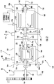
FIG. 2 is a schematic view of the generator arrangement ofFIG. 1 , showing an inboard shaft and an outboard shaft of the generator arrangement operatively associated with a permanent magnet generator and a main generator, respectively; -
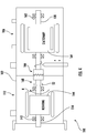
FIG. 3 is a schematic view of the generator arrangement ofFIG. 1 , showing the outboard shaft disconnected from the inboard shaft by engagement of a disconnect member, the permanent magnet generator continuing to provide electrical power; -
FIG. 4 is a schematic view of the generator arrangement ofFIG. 1 , showing the outboard shaft disconnected from the inboard shaft by fracture of a shear section, the permanent magnet generator continuing to provide electrical power; -
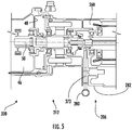
FIG. 5 is a cross-sectional view of a portion of the generator arrangement ofFIG. 1 according to an embodiment, showing a disconnect mechanism and a shear section coupling the main generator to the permanent magnet generator through the input shaft and the output shaft; and -
FIGS. 6 and7 are block diagrams of a method of generating electrical power, showing steps of the method according to an illustrative and non-limiting example of the method. - Reference will now be made to the drawings wherein like reference numerals identify similar structural features or aspects of the subject disclosure. For purposes of explanation and illustration, and not limitation, a partial view of an exemplary embodiment of a generator arrangement in accordance with the disclosure is shown in
FIG. 1 and is designated generally byreference character 100. Other embodiments of generator arrangements, accessory gearbox assemblies, and methods of generating electrical power in accordance with the present disclosure, or aspects thereof, are provided inFIGS. 2-7 , as will be described. The systems and methods described herein can be used for generating electrical power using more than one generator driven by a common input member, such as a main generator and a permanent magnet generator supported at a single mount of an accessory gearbox and driven by a gas turbine engine, though the present disclosure is not limited to accessory gearbox-drive generators or to any particular type of electrical generator in general. - With reference to
FIG. 1 , avehicle 10, e.g., an aircraft, is shown. Thevehicle 10 includes anelectrical system 12, a firstelectrical load 14, and a secondelectrical load 16. Thevehicle 10 also includes agas turbine engine 18 and an accessory gearbox assembly including theaccessory gearbox 20 and thegenerator arrangement 100. Although shown and described herein in the context of an aircraft electrical system it is to be understood and appreciated that other types of electrical systems can also benefit from the present disclosure. - The
gas turbine engine 18 includes acompressor 22, acombustor 24, and aturbine 26. Thecompressor 22 is configured to ingest air 28 from theexternal environment 30, compress the ingested air 28 to generate acompressed air flow 32, and provide thecompressed air flow 32 to thecombustor 24. Thecombustor 24 is in fluid communication with thecompressor 22, receives thecompressed air flow 32 from thecompressor 22, and generates a flow of highpressure combustion products 34. The flow of highpressure combustion products 34 are communicated to theturbine 26, which expands the highpressure combustion products 34 and extracts work from the expanding highpressure combustion products 34. A portion of the work is communicated to thegenerator arrangement 100 via theaccessory gearbox 20, which generates electric power using the mechanical rotation R. - The
electrical system 12 includes afirst bus 36 andsecond bus 38. Thefirst bus 36 electrically connects the firstelectrical load 14 to thegenerator arrangement 100 and provides a first flow ofelectric power 40 to the firstelectrical load 14. Thesecond bus 38 electrically connects the secondelectrical load 16 to thegenerator arrangement 100 and provides a second flowelectric power 42 to the secondelectrical load 16. In certain embodiments the firstelectrical load 14 can be a safety-critical electrical load carried by thevehicle 10, such as an engine controller or a FADEC device. In accordance with certain embodiments the secondelectrical load 16 can be a non-safety-critical electrical load carried by thevehicle 10, such as a lighting or convenience circuit. It is contemplated that the first flow ofelectric power 40 can be a flight-critical device flow of electric power and that the second flow ofelectric power 42 can be non-flight-critical device flow of electric power. - As will be appreciated by those of skill in the art in view of the present disclosure, in some electrical systems it can be desirable to provide power to safety-critical electrical loads using permanent magnet generators rather than main generators. This is due in part to the relative simplicity and perceived greater reliability of permanent magnet generators in relation to main generators. For this reason some electrical systems include both permanent magnet generators and main generators powered by separate mechanical inputs and each arranged as discrete line-replaceable units (LRUs). While generally acceptable for its intended purpose, mounting the permanent magnet generator and the main generator as discrete LRUs can limit the number of accessories that can be powered through an accessory gearbox. To avoid such limitations the
electrical system 12 incudes thegenerator arrangement 100. - With reference to
FIG. 2 , thegenerator arrangement 100 is shown. Thegenerator arrangement 100 generally includes ahousing 102 with a mountingfeature 104, amain generator 106 with anoutboard shaft 108 arranged within thehousing 102 and axially offset from the mountingfeature 104 along therotation axis 110, and apermanent magnet generator 112. Thepermanent magnet generator 112 has aninboard shaft 114 arranged within thehousing 102 and between themain generator 106 and the mountingfeature 104. Theoutboard shaft 108 is coupled to theinboard shaft 114 to communicate rotation R to themain generator 106 through thepermanent magnet generator 112. - The mounting
feature 104 is configured and adapted for mounting the generator arrangement at a singular mount of an accessory gearbox. In this respect thegenerator arrangement 100 is supported at anaccessory mount 44 of theaccessory gearbox 20. Theaccessory gearbox 20 in turn includes agear train 46, agearbox body 48, and aninput member 50. Thegearbox body 48 is arranged for coupling theaccessory mount 44, and therethrough thegenerator arrangement 100, to thegas turbine engine 18. Thegear train 46 is arranged within thegearbox body 48 and mechanically couples theinput member 50 to the turbine 26 (shown inFIG. 1 ). Theinput member 50 in turn extends through theaccessory mount 44 and is coupled to thePMG 112 and themain generator 106 for communicating mechanical rotation R thereto. In certain embodiment theinput member 50 is fixed in rotation relative to theinboard shaft 114. In accordance with certain embodiments theinput member 50 is coupled to the inboard shaft by an intermediate gear element, the intermediate gear element allowing thePMG 112 to be arranged off-axis relative to theoutboard shaft 108. Off-axis arrangements can provide the generator arrangement 100with axial compactness and/or allow thegenerator arrangement 100 to include more than one PMG. - The
housing 102 has aninboard end 116, anoutboard end 118, aPMG chamber 120, and amain generator chamber 122. The mountingfeature 104 is arranged on theinboard end 116 of thehousing 102. ThePMG chamber 120 and themain generator chamber 122 are defined within the interior of thehousing 102, thePMG chamber 120 arranged between themain generator chamber 122 and the mountingfeature 104. ThePMG 112 is arranged within thePMG chamber 120 and themain generator 106 is arranged within themain generator chamber 122. Aninboard seal member 124 is arranged on theinboard end 116 of thehousing 102, theinboard seal member 124 fluidly separating both thePMG chamber 120 and themain generator chamber 122 from theaccessory gearbox 20. Anoutboard seal member 126 is arranged within thehousing 102 between thePMG chamber 120 and themain generator chamber 122, theoutboard seal member 126 fluidly separating themain generator chamber 122 from thePMG chamber 120. - The
PMG 112 includes theinboard shaft 114, aPMG core 128, PMG magnets 130, and PMG coils 132. ThePMG 112 also includes a PMGelectrical connector 134, a PMGcoolant inlet port 136, a PMG coolant outlet port 138, and aPMG coolant circuit 140. - The
inboard shaft 114 is supported for rotation along therotation axis 110 within thePMG chamber 120, e.g., viaPMG bearings 142. In this respect thepermanent magnet generator 112 is supported for rotation independent ofmain generator 106. - The
PMG core 128 and the PMG magnets 130 are fixed in rotation relative to theinboard shaft 114 to form aPMG rotor 144. ThePMG coil 132 is fixed relative to thehousing 102 and is magnetically coupled to the PMG magnet 130 such that rotation of thePMG rotor 144 induces a flow of electric current in thePMG coil 132. ThePMG coil 132 is in turn electrically connected to the first electrical load 14 (shown inFIG. 1 ) by the PMGelectrical connector 134, thePMG 112 thereby providing the induced PMG current to the firstelectrical load 14 as the first flow of electric power 40 (shown inFIG. 1 ). - The
PMG coolant circuit 140 extends through thePMG chamber 120 and is in fluid communication with the PMGcoolant inlet port 136 and the PMG coolant outlet port 138. The PMGcoolant inlet port 136 and the PMG coolant outlet port 138 are in turn fixed to theinboard end 116 of thehousing 102, e.g., either (or both) located radially inward of mountingfeature 104, and are in fluid communication with theaccessory gearbox 20. In this respect theaccessory gearbox 20 is in fluid communication with thePMG chamber 120 to provide coolant and/or lubricant to thePMG 112 via thePMG coolant circuit 140. This allows theaccessory gearbox 20 to manage coolant and/or lubricant flow through thePMG 112. Further, as theoutboard seal member 126 fluidly separates themain generator chamber 122 from thePMG chamber 120, thegenerator arrangement 100 may further have a split coolant and/or lubricant arrangement, coolant and/or lubricant flow in themain generator chamber 122 being managed by themain generator 106. In certain embodiments the PMGcoolant inlet port 136 can be arranged radially inward of the mountingfeature 104, e.g., within theinboard shaft 114, simplifying installation and/or removal of thegenerator arrangement 100 from theaccessory gearbox 20. In accordance with certain embodiments, the PMG coolant outlet port 138 and the mountingfeature 104 can be arranged at a common radial location 146 (shown inFIG. 5 ), e.g., co-located with one another, also simplifying installation and/or removal of thegenerator arrangement 100 from theaccessory gearbox 20. - The
main generator 106 includes theoutboard shaft 108, a maingenerator rotor core 148, and maingenerator rotor coil 150. Themain generator 106 also includes a maingenerator stator coil 152, a main generatorelectrical connector 154, and a main generatorcoolant inlet port 156. Themain generator 106 further includes a main generatorcoolant outlet port 158 and a maingenerator coolant circuit 160. - The
outboard shaft 108 is supported for rotation along therotation axis 110 within themain generator chamber 122, e.g., viamain generator bearings 162. In this respect themain generator 106 is supported for cessation of rotation independent of rotation of thepermanent magnet generator 112. - The main
generator rotor core 148 and the maingenerator rotor coil 150 are fixed in rotation relative to theoutboard shaft 108 to form amain generator rotor 164. The maingenerator stator coil 152 is fixed relative to thehousing 102 and is magnetically coupled to the maingenerator rotor coil 150 such that rotation of themain generator rotor 164 induces a flow of electric current in the maingenerator stator coil 152. The maingenerator stator coil 152 is in turn electrically connected to the second electrical load 16 (shown inFIG. 1 ) by the main generatorelectrical connector 154, themain generator 106 thereby providing the induced main generator current to the secondelectrical load 16 as the second flow of electric power 42 (shown inFIG. 1 ). - The main
generator coolant circuit 160 extends through themain generator chamber 122 and is in fluid communication with the main generatorcoolant inlet port 156 and the main generatorcoolant outlet port 158. The main generatorcoolant inlet port 156 and the main generatorcoolant outlet port 158 are in turn fixed to theoutboard end 118 of thehousing 102 and are in fluid communication with an internal coolant/lubricant pump and an external coolant/lubricant heat exchanger. This allows themain generator 106 to manage coolant and/or lubricant flow through themain generator 106. In certain embodiments, coolant and/or lubricant flow through the main generator may be provided by an external coolant/lubricant pump. Further, as theoutboard seal member 126 fluidly separations themain generator chamber 122 from thePMG chamber 120, operation (or cessation of operation) of themain generator 106 and/or the maingenerator coolant circuit 160 does not impact coolant and/or lubricant flow through thePMG 112. - The
generator arrangement 100 also includes acoupling 166, ashear section 168, and adisconnect ramp 170. The generator arrangement further includes adisconnect member 172 anddisconnect solenoid 174. - The
coupling 166 connects theoutboard shaft 108 to theinboard shaft 114, and therethrough to theinput member 50. This allows theinput member 50 to drive the outboard shaft 108 (and thereby the main generator 106) through theinboard shaft 114 and thepermanent magnet generator 112. In the illustrated example thecoupling 166 includes inboardclutch teeth 176 and outboardclutch teeth 178. The inboard clutch teeth176 are fixed in rotation relative to theinboard shaft 114 and the outboardclutch teeth 178 are fixed in rotation relative to theoutboard shaft 108. In certain embodiments a biasingmember 180 can be arranged between theoutboard shaft 108 and thehousing 102, the biasingmember 180 urging the outboardclutch teeth 178 into engagement with the inboardclutch teeth 176 such thatmain generator rotor 164 rotates in concert with thePMG rotor 144. - With reference to
FIGS. 2 and3 , thedisconnect ramp 170 is fixed in rotation relative to theoutboard shaft 108. In certain embodiments thedisconnect ramp 170 is fixed in rotation relative to theoutboard shaft 108 between thecoupling 166 and themain generator bearings 162 supporting theoutboard shaft 108 for rotation relative to thehousing 102. This positioning limits the axial length of thegenerator arrangement 100. As will be appreciated by those of skill in art in view of the present disclosure, thedisconnect ramp 170 can be located at other positions relative to themain generator rotor 164 and remain within the scope of the present disclosure. - The
disconnect member 172 and thedisconnect solenoid 174 are located within thehousing 102. This provides compactness to thegenerator arrangement 100, enabling both thePMG 112 and themain generator 106 to be packaged as a single LRU. - The
disconnect member 172 is movable relative to thehousing 102 between a disengaged position A (shown inFIG. 2 ) and an engaged position B (shown inFIG. 3 ). As shown inFIG. 2 , in the disengaged position A thedisconnect member 172 is spaced apart from thedisconnect ramp 170. Spacing thedisconnect member 172 apart from thedisconnect ramp 170 allows the biasingmember 180 to drive the outboardclutch teeth 178 into engagement with the inboardclutch teeth 176. Engagement of the inboardclutch teeth 176 with the outboardclutch teeth 178 fixes theoutboard shaft 108 in rotation relative to theinboard shaft 114. Rotational fixation of theoutboard shaft 108 to theinboard shaft 114 in turn causes themain generator rotor 164 to rotate in concert with thePMG rotor 144 about therotation axis 110. The concerted rotation of themain generator rotor 164 and thePMG rotor 144 cause both themain generator 106 and thePMG 112 to generate electric power, thePMG 112 providing the first flow ofelectrical power 40 to the first electrical load 14 (shown inFIG. 1 ) and themain generator 106 providing the second flow ofelectric power 42 to the second electrical load 16 (shown inFIG. 1 ). - As shown in
FIG 3 , theoutboard shaft 108 is rotatable relative to theinboard shaft 114 when thedisconnect member 172 is in the disengaged position B. In this respect movement from the disengaged position A (shown inFIG. 2 ) to the engaged position B brings thedisconnect member 172 into mechanical engagement, i.e. contact, with thedisconnect ramp 170. Mechanical engagement of thedisconnect member 172 with thedisconnect ramp 170 in turn exerts adisconnect force 182 on theoutboard shaft 108 in a direction axially opposite a biasingforce 184 exerted by the biasingmember 180 on theoutboard shaft 108. - It is contemplated that the
disconnect force 182 is a magnitude greater than the biasingforce 184, thedisconnect member 172 thereby translating theoutboard shaft 108 axially along therotation axis 110 and in a direction opposite thePMG 112. Translation of theoutboard shaft 108 away from thePMG 112 in turn causes the outboardclutch teeth 178 to separate from the inboardclutch teeth 176, themain generator rotor 164 thereby ceasing concerted rotation of themain generator rotor 164 with thePMG rotor 144 about therotation axis 110. In certain embodiments it is contemplated that thePMG rotor 144 continues to rotate about therotation axis 110 such that thePMG 112 continues to provide the first flow ofelectric power 40 to the first electric load 14 (shown inFIG. 1 ), and that themain generator rotor 164 ceases rotation about the rotation axis 110 - themain generator 106 thereby ceasing to provide the second flow ofelectric power 42 to secondelectrical load 16. This allows for a commanded shutdown of themain generator 106, such as in the event that a main generator fault warrants shutdown of themain generator 106. - Movement of the
disconnect member 172 from the disengaged position A to the engaged position B is accomplished by thedisconnect solenoid 174. For example, in certain embodiments, thedisconnect member 172 may move to the engaged position B when power is applied to thedisconnect solenoid 174. As will be appreciated by those of skill in the art in view of the present disclosure, thedisconnect solenoid 174 allows for controlled disconnection of themain generator 106 from thePMG 112, and therethrough to the input member 50 (shown inFIG. 2 ). - Referring to
FIGS. 2 and4 , theshear section 168 is fixed in rotation relative to theinboard shaft 114. In certain embodiments the shear section168 is fixed in rotation relative to theinboard shaft 114 at a location between thecoupling 166 and thePMG bearings 142 supporting theinboard shaft 114 for rotation relative to thehousing 102. This positioning limits the likelihood of flail in the event that the shear section fractures during rotation by limiting elements remaining rotationally fixed to theinboard shaft 114 as a consequence of fracture of theshear section 168. As will be appreciated by those of skill in art in view of the present disclosure, theshear section 168 can be located at other positions relative to thePMG rotor 144 and remain within the scope of the present disclosure. - It is contemplated that the
shear section 168 be configured to fracture when load exerted on theinboard shaft 114 by theoutboard shaft 108 exceeds a predetermined value. As shown inFIG. 4 ,fracture 52 within theshear section 168 causes theoutboard shaft 108 to separate from theinboard shaft 114. Separation of theoutboard shaft 108 from theinboard shaft 114 renders theoutboard shaft 108 rotatable relative to theinboard shaft 114, themain generator 106 thereby disconnected from theinboard shaft 114 and therethrough the input member 50 (shown inFIG. 2 ). - In certain embodiments it is contemplated that the
PMG rotor 144 continue to rotate about therotation axis 110 such that thePMG 112 continues to provide the first flow ofelectric power 40 to the first electric load 14 (shown inFIG. 1 ), and that themain generator rotor 164 cease rotation about the rotation axis 110 - themain generator 106 thereby ceasing to provide the second flow ofelectric power 42 to second electrical load 16 - subsequent to thefracture 52. This allows for uncommanded shutdown of themain generator 106, such as in the event that themain generator 106 binds or becomes overloaded. As will be appreciated by those of skill in the art in view of the present disclosure, disconnection by fracture within theshear section 168 can be more rapid than commanded disconnects, limiting variation in first flow ofelectric power 40 in the event that themain generator 106 experiences a fault or becomes overloaded. - With reference to
FIG. 5 , a generator arrangement 200 is shown. The generator arrangement 200 is similar to the generator arrangement 100 (shown inFIG. 1 ) and additionally includes amain generator 206 having a self-contained maingenerator coolant circuit 260 and a manual main generator disconnect resetfeature 280. Thegenerator coolant circuit 260 is wholly contained within a main generator compartment 222 of the generator arrangement 200. The manual main generator disconnect resetfeature 280 is located on anexterior 282 of themain generator 206, is connected to adisconnect member 272, and is arranged to allow themain generator 206 to be reconnected to thePMG 212 following a commanded disconnect when the generator arrangement is at rest. A manual reset can be performed, for example, during servicing and/or maintenance events. - With reference to
FIG. 6 , amethod 300 of generating power with a generator arrangement, e.g., the generator arrangement 100 (shown inFIG. 1 ), is shown. Themethod 300 includes receiving mechanical rotation at an inboard shaft of a PMG of the generator arrangement, e.g., the inboard shaft 114 (shown inFIG. 2 ), as shown withbox 310. A main generator, e.g., the main generator 106 (shown inFIG. 1 ), is driven through the PMG by rotating an outboard shaft of the generator arrangement with the inboard shaft of the generator arrangement, as shown withbox 320. Power is provided to a first bus and a second bus, e.g., the first bus 36 (shown inFIG. 1 ) and the second bus 38 (shown inFIG. 1 ), as shown withboxes - As shown with
box 330, the main generator can be disconnected from the PMG. It is contemplated that the disconnection can be effected by engaging a disconnect member, e.g., the disconnect member 172 (shown inFIG. 2 ), by operation of a disconnect solenoid, e.g., the disconnect solenoid 174 (shown inFIG. 2 ). Disconnection of the main generator from the PMG by engagement of the disconnect member removes power from the second bus, as shown withbox 332. The PMG continues to be driven with the main generator disconnected from the PMG, as shown withbox 340, the PMG continuing to provide power to the first bus, as shown withbox 342. - As shown with
box 350, the main generator can thereafter be reconnected to the PMG when the generator arrangement is at rest. It is contemplated that reconnection of the main generator to the PMG be accomplished by disengaging the disconnect member, e.g., by pulling on themanual disconnect feature 280, such that the biasingmember 180 urges the outboardclutch teeth 178 into engagement with the inboardclutch teeth 176, the outboard shaft thereby becoming fixed in rotation relative to the inboard shaft. Reconnection of the main generator to the PMG causes the main generator to again be able to provide electric power to the second bus when the generator arrangement is restarted, as shown withbox 354. It is also contemplated that the PMG will continue to be able to provide electrical power to the first bus when the generator arrangement is restarted, as shown withbox 352. As shown witharrow 360, disconnection and reconnection of the main generator can recur iteratively. - With reference to
FIG. 7 , it is also contemplated that the main generator can be disconnected by operation of a shear section, e.g., the shear section 168 (shown inFIG. 3 ). In this respect mechanical rotation can be received at the inboard shaft of the PMG of the generator arrangement. The PMG and the main generator can be driven using the received rotation through the inboard shaft and the outboard shaft, as shown withbox 320. It is contemplated that mechanical rotation of the outboard shaft of the generator arrangement provides electrical power to the second bus using the main generator, as shown withbox 324. It is also contemplated that mechanical rotation of the inboard shaft of the generator arrangement provide electrical power to the first bus using the PMG, as shown withbox 322. - As shown with
box 370, the main generator can be disconnected from the PMG by fracture of the shear section, e.g., by torque exerted on the outboard shaft by the main generator above a predetermined value. Fracture of the shear section in turn removes power from the second bus, as shown withbox 372. Notwithstanding the fracture of the shear section the PMG continues to be driven by rotation received by the generator arrangement, as shown withbox 380, and the PMG continues to provide power to the first bus, as shown withbox 382. - Generators are commonly employed to provide electrical power to electrical loads in electrical systems, typically by communicating mechanical rotation to the generator from a rotation source such as a gas turbine engine. In certain electrical systems more than one generator is employed to provide electrical power. For example, a relatively simple PMG can be employed to provide electrical power to flight-critical loads, such as engine controllers, while a comparatively complex main generator provides electrical power to other loads less critical to operation of the aircraft. While generally acceptable for its intended purpose such electrical systems generally require that each generator occupy a separate mount on the accessory gearbox to receive electrical power individually as separate line-replaceable units.
- In embodiments described herein generator arrangements include both a PMG and a main generator powered collective with a single a common input member. The PMG is mounted to a single accessory gearbox mount inboard of the main generator such that mechanical rotation received from the accessory gearbox rotates the PMG through an inboard shaft and the main generator through an outboard shaft fixed in rotation relative to the inboard shaft. In certain embodiments a disconnect member is incorporated in the generator arrangement, allowing the main generator to be disconnected without interruption of power provided by the PMG and reconnected to the accessory gearbox through the PMG without interruption of power provided by the PMG when the generator arrangement is at rest. In accordance with certain embodiments the outboard shaft can include a shear section, also allowing the main generator to be disconnected from the accessory gearbox without interrupting power provided by the PMG.
- The term "about" is intended to include the degree of error associated with measurement of the particular quantity based upon the equipment available at the time of filing the application.
- The terminology used herein is for the purpose of describing particular embodiments only and is not intended to be limiting of the present disclosure. As used herein, the singular forms "a", "an" and "the" are intended to include the plural forms as well, unless the context clearly indicates otherwise. It will be further understood that the terms "comprises" and/or "comprising," when used in this specification, specify the presence of stated features, integers, steps, operations, elements, and/or components, but do not preclude the presence or addition of one or more other features, integers, steps, operations, element components, and/or groups thereof.
- While the present disclosure has been described with reference to an exemplary embodiment or embodiments, it will be understood by those skilled in the art that various changes may be made and equivalents may be substituted for elements thereof without departing from the scope of the present disclosure. In addition, many modifications may be made to adapt a particular situation or material to the teachings of the present disclosure without departing from the essential scope thereof. Therefore, it is intended that the present disclosure not be limited to the particular embodiment disclosed as the best mode contemplated for carrying out this present disclosure, but that the present disclosure will include all embodiments falling within the scope of the claims.
Claims (15)
- A generator arrangement (100), comprising:a housing (102) with a mounting feature (104);a main generator (106) with an outboard shaft (108) arranged within the housing and axially offset from the mounting feature along a rotation axis; anda permanent magnet generator (112) with an inboard shaft (114) arranged within the housing between the main generator and the mounting feature, wherein the outboard shaft is coupled to the inboard shaft to provide rotation to the main generator through the permanent magnet generator.
- The generator arrangement as recited in claim 1, wherein the housing defines a permanent magnet generator chamber and a main generator chamber, the permanent magnet generator chamber arranged axially between the mounting feature and the main generator chamber.
- The generator arrangement as recited in claim 2, further comprising an inboard seal member fluidly separating the permanent magnet generator chamber and the main generator chamber from the external environment.
- The generator arrangement as recited in claim 2 or 3, further comprising an outboard seal member fluidly separating the permanent magnet generator chamber from the main generator chamber; and/or wherein the permanent magnet generator is arranged within the permanent magnet generator chamber, wherein the main generator is arranged within the main generator chamber.
- The generator arrangement as recited in any preceding claim, further comprising:a permanent magnet generator coolant circuit arranged within the housing and in thermal communication with the permanent magnet generator; anda main generator coolant circuit arranged within the housing and in thermal communication with the main generator, wherein the main generator coolant circuit is fluidly isolated from the permanent magnet generator coolant circuit.
- The generator arrangement as recited in claim 5, further comprising a permanent magnet generator coolant inlet port in fluid communication with the permanent magnet generator coolant circuit, the permanent magnet generator coolant inlet port arranged radially inward of the mounting feature; and/or further comprising a permanent magnet generator coolant outlet port in fluid communication with the permanent magnet generator coolant circuit, the permanent magnet generator coolant outlet port and the mounting feature arranged at a common radial location.
- The generator arrangement as recited in any preceding claim, further comprising a coupling connecting the outboard shaft to the inboard shaft.
- The generator arrangement as recited in claim 7, wherein the coupling comprises:inboard clutch teeth fixed in rotation relative to the inboard shaft;outboard clutch teeth fixed in rotation relative to the outboard shaft; anda biasing member urging the outboard clutch teeth into mechanical engagement with the inboard clutch teeth; and/orfurther comprising a shear section fixed in rotation relative to the inboard shaft between the coupling and inboard bearings, the inboard bearings supporting the inboard shaft for rotation relative to the housing; and/orfurther comprising a disconnect ramp fixed in rotation relative to the outboard shaft between the coupling and outboard bearing supporting the outboard shaft for rotation relative to the housing.
- The generator arrangement as recited in any preceding claim, further comprising a disconnect member movable relative to the housing between a disengaged position and an engaged position, wherein the outboard shaft is fixed in rotation relative the inboard shaft in the disengaged position, wherein the outboard shaft is rotatable relative to the inboard shaft in the engaged position.
- The generator arrangement as recited in claim 9, further comprising a disconnect ramp fixed in rotation relative to the outboard shaft, the disconnect member spaced apart from the ramp structure in the disengaged position, the disconnect member abutting the ramp structure in the engaged position; and/or further comprising a disconnect solenoid arranged within the housing and operably connected to the disconnect member.
- An accessory gearbox assembly, comprising:a generator arrangement as recited in claim 1, wherein the housing defines a permanent magnet generator chamber and a main generator chamber, the permanent magnet generator chamber arranged axially between the mounting feature and the main generator chamber; andan accessory gearbox with a mount and an input member, the mounting feature fixing the generator arrangement to the mount, and the input member fixed in rotation relative to the inboard shaft.
- The accessory gearbox assembly as recited in claim 11, further comprising:a permanent magnet generator coolant circuit arranged within the housing and in thermal communication with the permanent magnet generator;a main generator coolant circuit arranged within the housing and in thermal communication with the main generator, wherein the main generator coolant circuit is fluidly isolated from the permanent magnet generator coolant circuit;a coupling connecting the outboard shaft to the inboard shaft; anda disconnect member movable relative to the housing between a disengaged position and an engaged position, wherein the outboard shaft is fixed in rotation relative the inboard shaft in the disengaged position, wherein the outboard shaft rotatable relative to the inboard shaft in the engaged position.
- A method of generating power, comprising:at a generator arrangement including a housing with a mounting feature, a main generator with an outboard shaft arranged within the housing and axially offset from the mounting feature along a rotation axis, and a permanent magnet generator with an inboard shaft arranged within the housing between the main generator and the mounting feature, the outboard shaft coupled to the inboard shaft;receiving mechanical rotation at the inboard shaft of the permanent magnet generator; anddriving the main generator through the permanent magnet generator by rotating the outboard shaft of the main generator with the inboard shaft of the permanent magnet generator.
- The method as recited in claim 13, wherein the generator arrangement further comprises a disconnect member movable relative to the housing between a disengaged position and an engaged position, the method further comprising:disconnecting the main generator from the permanent magnet generator with the disconnect member by engaging the disconnect member; andcontinuing to drive the permanent magnet generator after disconnecting the main generator from the permanent magnet generator.
- The method as recited in claim 13 or 14, wherein the generator arrangement further comprises a shear section fixed in rotation relative to the inboard shaft, the method further comprising:disconnecting the main generator from the permanent magnet generator by fracturing the shear section; andcontinuing to drive the permanent magnet generator after disconnecting the main generator from the permanent magnet generator.
Applications Claiming Priority (1)
| Application Number | Priority Date | Filing Date | Title |
|---|---|---|---|
| US16/563,223 US11152837B2 (en) | 2019-09-06 | 2019-09-06 | Generator arrangements and methods of generating electric power with generator arrangements |
Publications (1)
| Publication Number | Publication Date |
|---|---|
| EP3790175A1 true EP3790175A1 (en) | 2021-03-10 |
Family
ID=68886833
Family Applications (1)
| Application Number | Title | Priority Date | Filing Date |
|---|---|---|---|
| EP19215240.3A Pending EP3790175A1 (en) | 2019-09-06 | 2019-12-11 | Generator arrangements and methods of generating electric power with generator arrangements |
Country Status (2)
| Country | Link |
|---|---|
| US (1) | US11152837B2 (en) |
| EP (1) | EP3790175A1 (en) |
Families Citing this family (2)
| Publication number | Priority date | Publication date | Assignee | Title |
|---|---|---|---|---|
| US11859552B2 (en) * | 2021-04-30 | 2024-01-02 | Rtx Corporation | Flow recirculative power system |
| US12328086B2 (en) * | 2022-05-27 | 2025-06-10 | Rolls-Royce Corporation | Aircraft with engine-driven permanent magnet generator |
Citations (9)
| Publication number | Priority date | Publication date | Assignee | Title |
|---|---|---|---|---|
| US5691584A (en) * | 1993-09-09 | 1997-11-25 | Honda Giken Kogyo Kabushiki Kaisha | Wheel motor for vehicles |
| US20060105642A1 (en) * | 2001-11-29 | 2006-05-18 | Gunter Ries | Boat propulsion system |
| DE102007025954A1 (en) * | 2007-06-04 | 2008-12-11 | Robert Bosch Gmbh | Electric machine system |
| US20110211979A1 (en) * | 2010-02-26 | 2011-09-01 | Behrend Goswin Schlenhoff | Cooling system for a multistage electric motor |
| US20110273043A1 (en) * | 2010-05-05 | 2011-11-10 | Oeco, Llc | High reliability generator with dual drive path |
| US20140191599A1 (en) * | 2011-06-28 | 2014-07-10 | Philsung Co., Ltd. | Generator having variable power generation |
| US20170016489A1 (en) * | 2015-07-15 | 2017-01-19 | Hamilton Sundstrand Corporation | Disconnect mechanisms |
| EP3171496A1 (en) * | 2015-11-18 | 2017-05-24 | Baumüller Nürnberg GmbH | Motor assembly |
| US20180013338A1 (en) * | 2015-01-30 | 2018-01-11 | Gkn Automotive Ltd. | Electric drive assembly |
Family Cites Families (4)
| Publication number | Priority date | Publication date | Assignee | Title |
|---|---|---|---|---|
| US4139780A (en) | 1977-11-17 | 1979-02-13 | Sundstrand Corporation | Multi-channel generator drive system |
| US4868406A (en) | 1988-07-05 | 1989-09-19 | Sundstrand Corporation | Electrically compensated constant speed drive with prime mover start capability |
| US9574618B2 (en) | 2014-11-20 | 2017-02-21 | Hamilton Sundstrand Corporation | Thermal disconnect assembly with flight control permanent magnet generator for integrated drive generator |
| US10634063B2 (en) | 2018-01-04 | 2020-04-28 | Hamilton Sundstrand Corporation | Input shaft for use in integrated drive generator |
-
2019
- 2019-09-06 US US16/563,223 patent/US11152837B2/en active Active
- 2019-12-11 EP EP19215240.3A patent/EP3790175A1/en active Pending
Patent Citations (9)
| Publication number | Priority date | Publication date | Assignee | Title |
|---|---|---|---|---|
| US5691584A (en) * | 1993-09-09 | 1997-11-25 | Honda Giken Kogyo Kabushiki Kaisha | Wheel motor for vehicles |
| US20060105642A1 (en) * | 2001-11-29 | 2006-05-18 | Gunter Ries | Boat propulsion system |
| DE102007025954A1 (en) * | 2007-06-04 | 2008-12-11 | Robert Bosch Gmbh | Electric machine system |
| US20110211979A1 (en) * | 2010-02-26 | 2011-09-01 | Behrend Goswin Schlenhoff | Cooling system for a multistage electric motor |
| US20110273043A1 (en) * | 2010-05-05 | 2011-11-10 | Oeco, Llc | High reliability generator with dual drive path |
| US20140191599A1 (en) * | 2011-06-28 | 2014-07-10 | Philsung Co., Ltd. | Generator having variable power generation |
| US20180013338A1 (en) * | 2015-01-30 | 2018-01-11 | Gkn Automotive Ltd. | Electric drive assembly |
| US20170016489A1 (en) * | 2015-07-15 | 2017-01-19 | Hamilton Sundstrand Corporation | Disconnect mechanisms |
| EP3171496A1 (en) * | 2015-11-18 | 2017-05-24 | Baumüller Nürnberg GmbH | Motor assembly |
Also Published As
| Publication number | Publication date |
|---|---|
| US11152837B2 (en) | 2021-10-19 |
| US20210075292A1 (en) | 2021-03-11 |
Similar Documents
| Publication | Publication Date | Title |
|---|---|---|
| US5555722A (en) | Integrated APU | |
| RU2445481C2 (en) | Distributed architecture of gas turbine starter-generator | |
| US10717543B2 (en) | Apparatus and methods for powering an electrical device associated with an aircraft rotor | |
| CN109690052B (en) | Shaft breaking device for generator | |
| US20060137355A1 (en) | Fan driven emergency generator | |
| US10336442B2 (en) | Non-lubricated architecture for a turboshaft engine | |
| EP2977314B1 (en) | Propeller in-hub power generation and control | |
| US8432079B2 (en) | 2-pole generator packaging arrangement | |
| EP2390989A2 (en) | High reliability generator with dual drive path | |
| JP2008057541A (en) | Device for driving rotor of auxiliary equipment of turbine engine | |
| US11152837B2 (en) | Generator arrangements and methods of generating electric power with generator arrangements | |
| JP7416081B2 (en) | Generator and multi-shaft gas turbine engine for aircraft equipped with the generator | |
| CN110291282B (en) | Air turbine starter with separator | |
| CN116490682B (en) | Free turbine type turbine generator comprising a reversible electric machine coupled to a free turbine | |
| EP2822155B1 (en) | Integrated gas turbine engine accessories | |
| GB2592977A (en) | Generator accessory drive |
Legal Events
| Date | Code | Title | Description |
|---|---|---|---|
| PUAI | Public reference made under article 153(3) epc to a published international application that has entered the european phase |
Free format text: ORIGINAL CODE: 0009012 |
|
| STAA | Information on the status of an ep patent application or granted ep patent |
Free format text: STATUS: THE APPLICATION HAS BEEN PUBLISHED |
|
| AK | Designated contracting states |
Kind code of ref document: A1 Designated state(s): AL AT BE BG CH CY CZ DE DK EE ES FI FR GB GR HR HU IE IS IT LI LT LU LV MC MK MT NL NO PL PT RO RS SE SI SK SM TR |
|
| AX | Request for extension of the european patent |
Extension state: BA ME |
|
| STAA | Information on the status of an ep patent application or granted ep patent |
Free format text: STATUS: REQUEST FOR EXAMINATION WAS MADE |
|
| 17P | Request for examination filed |
Effective date: 20210908 |
|
| RBV | Designated contracting states (corrected) |
Designated state(s): AL AT BE BG CH CY CZ DE DK EE ES FI FR GB GR HR HU IE IS IT LI LT LU LV MC MK MT NL NO PL PT RO RS SE SI SK SM TR |
|
| STAA | Information on the status of an ep patent application or granted ep patent |
Free format text: STATUS: EXAMINATION IS IN PROGRESS |
|
| 17Q | First examination report despatched |
Effective date: 20221216 |