EP3790128A1 - Detachable power cord structure for portable hair curler - Google Patents
Detachable power cord structure for portable hair curler Download PDFInfo
- Publication number
- EP3790128A1 EP3790128A1 EP20151723.2A EP20151723A EP3790128A1 EP 3790128 A1 EP3790128 A1 EP 3790128A1 EP 20151723 A EP20151723 A EP 20151723A EP 3790128 A1 EP3790128 A1 EP 3790128A1
- Authority
- EP
- European Patent Office
- Prior art keywords
- tail
- power cord
- hair curler
- portable hair
- cord structure
- Prior art date
- Legal status (The legal status is an assumption and is not a legal conclusion. Google has not performed a legal analysis and makes no representation as to the accuracy of the status listed.)
- Granted
Links
Images
Classifications
-
- H—ELECTRICITY
- H01—ELECTRIC ELEMENTS
- H01R—ELECTRICALLY-CONDUCTIVE CONNECTIONS; STRUCTURAL ASSOCIATIONS OF A PLURALITY OF MUTUALLY-INSULATED ELECTRICAL CONNECTING ELEMENTS; COUPLING DEVICES; CURRENT COLLECTORS
- H01R13/00—Details of coupling devices of the kinds covered by groups H01R12/70 or H01R24/00 - H01R33/00
- H01R13/62—Means for facilitating engagement or disengagement of coupling parts or for holding them in engagement
- H01R13/627—Snap or like fastening
- H01R13/6277—Snap or like fastening comprising annular latching means, e.g. ring snapping in an annular groove
-
- H—ELECTRICITY
- H01—ELECTRIC ELEMENTS
- H01R—ELECTRICALLY-CONDUCTIVE CONNECTIONS; STRUCTURAL ASSOCIATIONS OF A PLURALITY OF MUTUALLY-INSULATED ELECTRICAL CONNECTING ELEMENTS; COUPLING DEVICES; CURRENT COLLECTORS
- H01R35/00—Flexible or turnable line connectors, i.e. the rotation angle being limited
-
- H—ELECTRICITY
- H01—ELECTRIC ELEMENTS
- H01R—ELECTRICALLY-CONDUCTIVE CONNECTIONS; STRUCTURAL ASSOCIATIONS OF A PLURALITY OF MUTUALLY-INSULATED ELECTRICAL CONNECTING ELEMENTS; COUPLING DEVICES; CURRENT COLLECTORS
- H01R13/00—Details of coupling devices of the kinds covered by groups H01R12/70 or H01R24/00 - H01R33/00
- H01R13/02—Contact members
- H01R13/15—Pins, blades or sockets having separate spring member for producing or increasing contact pressure
- H01R13/187—Pins, blades or sockets having separate spring member for producing or increasing contact pressure with spring member in the socket
-
- A—HUMAN NECESSITIES
- A45—HAND OR TRAVELLING ARTICLES
- A45D—HAIRDRESSING OR SHAVING EQUIPMENT; EQUIPMENT FOR COSMETICS OR COSMETIC TREATMENTS, e.g. FOR MANICURING OR PEDICURING
- A45D20/00—Hair drying devices; Accessories therefor
- A45D20/04—Hot-air producers
- A45D20/08—Hot-air producers heated electrically
- A45D20/10—Hand-held drying devices, e.g. air douches
-
- A—HUMAN NECESSITIES
- A45—HAND OR TRAVELLING ARTICLES
- A45D—HAIRDRESSING OR SHAVING EQUIPMENT; EQUIPMENT FOR COSMETICS OR COSMETIC TREATMENTS, e.g. FOR MANICURING OR PEDICURING
- A45D1/00—Curling-tongs, i.e. tongs for use when hot; Curling-irons, i.e. irons for use when hot; Accessories therefor
- A45D1/20—External heating means for curling-tongs or curling-irons
-
- A—HUMAN NECESSITIES
- A45—HAND OR TRAVELLING ARTICLES
- A45D—HAIRDRESSING OR SHAVING EQUIPMENT; EQUIPMENT FOR COSMETICS OR COSMETIC TREATMENTS, e.g. FOR MANICURING OR PEDICURING
- A45D20/00—Hair drying devices; Accessories therefor
- A45D20/04—Hot-air producers
- A45D20/08—Hot-air producers heated electrically
- A45D20/10—Hand-held drying devices, e.g. air douches
- A45D20/12—Details thereof or accessories therefor, e.g. nozzles, stands
-
- H—ELECTRICITY
- H01—ELECTRIC ELEMENTS
- H01R—ELECTRICALLY-CONDUCTIVE CONNECTIONS; STRUCTURAL ASSOCIATIONS OF A PLURALITY OF MUTUALLY-INSULATED ELECTRICAL CONNECTING ELEMENTS; COUPLING DEVICES; CURRENT COLLECTORS
- H01R13/00—Details of coupling devices of the kinds covered by groups H01R12/70 or H01R24/00 - H01R33/00
- H01R13/02—Contact members
- H01R13/10—Sockets for co-operation with pins or blades
-
- H—ELECTRICITY
- H01—ELECTRIC ELEMENTS
- H01R—ELECTRICALLY-CONDUCTIVE CONNECTIONS; STRUCTURAL ASSOCIATIONS OF A PLURALITY OF MUTUALLY-INSULATED ELECTRICAL CONNECTING ELEMENTS; COUPLING DEVICES; CURRENT COLLECTORS
- H01R13/00—Details of coupling devices of the kinds covered by groups H01R12/70 or H01R24/00 - H01R33/00
- H01R13/02—Contact members
- H01R13/22—Contacts for co-operating by abutting
-
- H—ELECTRICITY
- H01—ELECTRIC ELEMENTS
- H01R—ELECTRICALLY-CONDUCTIVE CONNECTIONS; STRUCTURAL ASSOCIATIONS OF A PLURALITY OF MUTUALLY-INSULATED ELECTRICAL CONNECTING ELEMENTS; COUPLING DEVICES; CURRENT COLLECTORS
- H01R13/00—Details of coupling devices of the kinds covered by groups H01R12/70 or H01R24/00 - H01R33/00
- H01R13/62—Means for facilitating engagement or disengagement of coupling parts or for holding them in engagement
- H01R13/629—Additional means for facilitating engagement or disengagement of coupling parts, e.g. aligning or guiding means, levers, gas pressure electrical locking indicators, manufacturing tolerances
- H01R13/631—Additional means for facilitating engagement or disengagement of coupling parts, e.g. aligning or guiding means, levers, gas pressure electrical locking indicators, manufacturing tolerances for engagement only
- H01R13/6315—Additional means for facilitating engagement or disengagement of coupling parts, e.g. aligning or guiding means, levers, gas pressure electrical locking indicators, manufacturing tolerances for engagement only allowing relative movement between coupling parts, e.g. floating connection
-
- H—ELECTRICITY
- H01—ELECTRIC ELEMENTS
- H01R—ELECTRICALLY-CONDUCTIVE CONNECTIONS; STRUCTURAL ASSOCIATIONS OF A PLURALITY OF MUTUALLY-INSULATED ELECTRICAL CONNECTING ELEMENTS; COUPLING DEVICES; CURRENT COLLECTORS
- H01R13/00—Details of coupling devices of the kinds covered by groups H01R12/70 or H01R24/00 - H01R33/00
- H01R13/62—Means for facilitating engagement or disengagement of coupling parts or for holding them in engagement
- H01R13/639—Additional means for holding or locking coupling parts together, after engagement, e.g. separate keylock, retainer strap
-
- H—ELECTRICITY
- H01—ELECTRIC ELEMENTS
- H01R—ELECTRICALLY-CONDUCTIVE CONNECTIONS; STRUCTURAL ASSOCIATIONS OF A PLURALITY OF MUTUALLY-INSULATED ELECTRICAL CONNECTING ELEMENTS; COUPLING DEVICES; CURRENT COLLECTORS
- H01R24/00—Two-part coupling devices, or either of their cooperating parts, characterised by their overall structure
- H01R24/20—Coupling parts carrying sockets, clips or analogous contacts and secured only to wire or cable
-
- H—ELECTRICITY
- H01—ELECTRIC ELEMENTS
- H01R—ELECTRICALLY-CONDUCTIVE CONNECTIONS; STRUCTURAL ASSOCIATIONS OF A PLURALITY OF MUTUALLY-INSULATED ELECTRICAL CONNECTING ELEMENTS; COUPLING DEVICES; CURRENT COLLECTORS
- H01R24/00—Two-part coupling devices, or either of their cooperating parts, characterised by their overall structure
- H01R24/28—Coupling parts carrying pins, blades or analogous contacts and secured only to wire or cable
-
- H—ELECTRICITY
- H01—ELECTRIC ELEMENTS
- H01R—ELECTRICALLY-CONDUCTIVE CONNECTIONS; STRUCTURAL ASSOCIATIONS OF A PLURALITY OF MUTUALLY-INSULATED ELECTRICAL CONNECTING ELEMENTS; COUPLING DEVICES; CURRENT COLLECTORS
- H01R24/00—Two-part coupling devices, or either of their cooperating parts, characterised by their overall structure
- H01R24/38—Two-part coupling devices, or either of their cooperating parts, characterised by their overall structure having concentrically or coaxially arranged contacts
-
- H—ELECTRICITY
- H01—ELECTRIC ELEMENTS
- H01R—ELECTRICALLY-CONDUCTIVE CONNECTIONS; STRUCTURAL ASSOCIATIONS OF A PLURALITY OF MUTUALLY-INSULATED ELECTRICAL CONNECTING ELEMENTS; COUPLING DEVICES; CURRENT COLLECTORS
- H01R31/00—Coupling parts supported only by co-operation with counterpart
- H01R31/06—Intermediate parts for linking two coupling parts, e.g. adapter
-
- H—ELECTRICITY
- H01—ELECTRIC ELEMENTS
- H01R—ELECTRICALLY-CONDUCTIVE CONNECTIONS; STRUCTURAL ASSOCIATIONS OF A PLURALITY OF MUTUALLY-INSULATED ELECTRICAL CONNECTING ELEMENTS; COUPLING DEVICES; CURRENT COLLECTORS
- H01R39/00—Rotary current collectors, distributors or interrupters
- H01R39/64—Devices for uninterrupted current collection
-
- A—HUMAN NECESSITIES
- A45—HAND OR TRAVELLING ARTICLES
- A45D—HAIRDRESSING OR SHAVING EQUIPMENT; EQUIPMENT FOR COSMETICS OR COSMETIC TREATMENTS, e.g. FOR MANICURING OR PEDICURING
- A45D2/00—Hair-curling or hair-waving appliances ; Appliances for hair dressing treatment not otherwise provided for
-
- A—HUMAN NECESSITIES
- A45—HAND OR TRAVELLING ARTICLES
- A45D—HAIRDRESSING OR SHAVING EQUIPMENT; EQUIPMENT FOR COSMETICS OR COSMETIC TREATMENTS, e.g. FOR MANICURING OR PEDICURING
- A45D1/00—Curling-tongs, i.e. tongs for use when hot; Curling-irons, i.e. irons for use when hot; Accessories therefor
- A45D2001/002—Accessories therefor
-
- A—HUMAN NECESSITIES
- A45—HAND OR TRAVELLING ARTICLES
- A45D—HAIRDRESSING OR SHAVING EQUIPMENT; EQUIPMENT FOR COSMETICS OR COSMETIC TREATMENTS, e.g. FOR MANICURING OR PEDICURING
- A45D6/00—Details of, or accessories for, hair-curling or hair-waving devices
- A45D2006/005—Accessories therefor
Definitions
- the present invention relates to a hairdressing product, in particular to a detachable power cord structure for a portable hair curler.
- the purpose of the present invention is to provide a detachable power cord structure for a portable hair curler in view of the above drawbacks of the related art.
- a detachable power cord structure for a portable hair curler including a device tail sleeve and a tail wire, wherein the device sleeve is provided with an elastic engaging assembly, the tail wire is inserted into the device tail sleeve and is engaged with the elastic engaging assembly.
- the tail wire When the tail wire is engaged with the elastic engaging assembly, it can turn on the circuit and can be rotated freely.
- the elastic engaging assembly includes a tail spring ring, one end of the tail spring ring that extends into the device tail sleeve is provided with a buckle, and a protrusion is disposed on an inner side of the buckle.
- a spring groove is provided on an inner side wall of the device tail sleeve, and a tail spring is disposed in the spring groove, the tail spring ring extends into the device tail sleeve and abuts against the tail spring.
- the tail wire has an insertion end, and the outer side of the insertion end is provided with an annular groove.
- the axial center of the insertion end is provided with a positive insertion port, and the insertion end is further provided with an annular negative insertion slot, and the protrusion of the buckle is docked with the annular groove.
- a socket terminal is further provided in the device tail sleeve, and the socket terminal is provided with a positive contact pin and an annular negative contact piece.
- the positive contact pin is inserted into the positive insertion port in an aligned manner, and the annular negative contact piece is docked with the annular negative insertion slot.
- the buckle moves along with the tail spring ring and is detached from the tail wire.
- the annular negative insertion slot is provided with a power negative contact terminal
- the positive insertion port is provided with a power positive contact terminal therein.
- the power negative contact terminal is disposed around the annular negative insertion slot.
- the other end of the tail wire is a power cord buried end, and an angle greater than 90 degrees is formed between the power cord buried end and the insertion end.
- a side of the power cord buried end is provided with a hanging hole.
- the power cord buried end and the insertion end are integrally injection molded.
- the present invention has the advantages that the power connector structure adopted by the present invention can be rotated through the insertion of the device tail sleeve and the tail wire, and the elastic engaging assembly is arranged in the device tail sleeve.
- the tail wire is inserted into the device tail sleeve and is engaged with the elastic engaging assembly.
- the tail wire can turn on the circuit and rotated freely.
- the tail wire is electrically connected, it can be rotated freely without bending or curving during use, thereby effectively ensuring the service life of the tail wire, and to some extent, it has a protective effect on the power cord.
- the power connector of the product can be adapted to the power docking of various hairdressing appliances, can be replaced at will, and has high versatility.
- a detachable power cord structure for a portable hair curler includes a device tail sleeve 11 and a tail wire 12.
- An elastic engaging assembly 101 is arranged in the device tail sleeve 11.
- the tail wire 12 is inserted into the device tail sleeve 11 and is engaged with the elastic engaging assembly 101.
- the tail wire 12 When the tail wire 12 is engaged into the elastic engaging assembly 101, it can turn on the circuit and can be rotated freely.
- the elastic engaging assembly 101 includes a tail spring ring 102.
- One end of the tail spring ring 102 extending into the device tail sleeve 11 is provided with a buckle 103.
- the inside of the buckle 103 is provided with a protrusion 104, and a spring groove 105 is disposed on the inner side wall of the device tail sleeve 11.
- a tail spring 106 is disposed in the spring groove 105.
- the tail spring ring 102 extends into the device tail sleeve 11 and abuts against the tail spring 106.
- the tail wire 12 has an insertion end 107.
- the outer side of the insertion end 107 is provided with an annular groove 108.
- the axial center of the insertion end 107 is provided with a positive insertion port 109, and the insertion end 107 is further provided with an annular negative insertion slot 110 therein.
- the protrusion 104 of the buckle 103 is docked with the annular groove 108.
- the device tail sleeve 11 is further provided with a socket terminal 111.
- the socket terminal 111 is provided with a positive contact pin 112 and an annular negative contact piece 113.
- the positive contact pin 112 is inserted into the positive insertion port 109 in an aligned manner, and the annular negative contact piece 113 is docked with the annular negative insertion slot 110.
- the socket terminal 111 is electrically connected to a PCB board 5.
- the buckle 103 moves along with the tail spring ring 102 and is detached from the tail wire 12.
- the annular negative insertion slot 110 is provided with a power negative contact terminal
- the positive insertion port 109 is provided with a power positive contact terminal therein.
- the power negative contact terminal is disposed around the annular negative insertion slot 110.
- the power negative contact terminal can completely contact the terminal to ensure electrical connection.
- the annular negative insertion slot 110 has a certain insertion and positioning function.
- the other end of the tail wire 12 is a power cord buried end 114, and an angle greater than 90 degrees is formed between the power cord buried end 114 and the insertion end 107.
- a side of the power cord buried end 114 is provided with a hanging hole 115.
- the hanging hole 115 facilitates the hanging of the power connector and makes it easy for the worker to pick and place.
- the power cord buried end 114 and the insertion end 107 are integrally formed by injection molding.
- the power positive contact terminal and the power negative contact terminal are all hidden in the tail wire, and the safety performance is higher.
- the power connector structure adopted by the present invention can be rotated through insertion of the device tail sleeve and the tail wire.
- An elastic engaging assembly is arranged in the device tail sleeve, the tail wire is inserted into the device tail sleeve and is engaged with the elastic engaging assembly.
- the tail wire When the tail wire is engaged into the elastic engaging assembly, it can turn on the circuit and can be rotated freely.
- the tail wire is electrically connected, it can be rotated freely without bending or curing during use, thereby effectively ensuring the service life of the tail wire.
Landscapes
- Hair Curling (AREA)
- Details Of Connecting Devices For Male And Female Coupling (AREA)
Abstract
Description
- The present invention relates to a hairdressing product, in particular to a detachable power cord structure for a portable hair curler.
- At present, there are many kinds of electrical appliances for hairdressing, which have different functions according to different hairdressing effects, such as: hair curler, hair-straightening comb, hair-curling comb, hair iron, hair dryer, electric hair dryer comb or hair straightener, etc. The existing power connector parts of these appliances are generally connected through a fixed power cord slot on the casing. For power connectors that cannot be detached, they cannot be easily carried and arranged in places. This application can solve the above problems.
- The purpose of the present invention is to provide a detachable power cord structure for a portable hair curler in view of the above drawbacks of the related art.
- In order to solve the above-mentioned defects of the related art, the technical solution provided by the present invention is: a detachable power cord structure for a portable hair curler, including a device tail sleeve and a tail wire, wherein the device sleeve is provided with an elastic engaging assembly, the tail wire is inserted into the device tail sleeve and is engaged with the elastic engaging assembly. When the tail wire is engaged with the elastic engaging assembly, it can turn on the circuit and can be rotated freely.
- As an improvement of the detachable power cord structure for the portable hair curler of the present invention, the elastic engaging assembly includes a tail spring ring, one end of the tail spring ring that extends into the device tail sleeve is provided with a buckle, and a protrusion is disposed on an inner side of the buckle. A spring groove is provided on an inner side wall of the device tail sleeve, and a tail spring is disposed in the spring groove, the tail spring ring extends into the device tail sleeve and abuts against the tail spring.
- As an improvement of the detachable power cord structure for the portable hair curler of the present invention, the tail wire has an insertion end, and the outer side of the insertion end is provided with an annular groove. The axial center of the insertion end is provided with a positive insertion port, and the insertion end is further provided with an annular negative insertion slot, and the protrusion of the buckle is docked with the annular groove.
- As an improvement of the detachable power cord structure for the portable hair curler of the present invention, a socket terminal is further provided in the device tail sleeve, and the socket terminal is provided with a positive contact pin and an annular negative contact piece. The positive contact pin is inserted into the positive insertion port in an aligned manner, and the annular negative contact piece is docked with the annular negative insertion slot.
- As an improvement of the detachable power cord structure of the portable hair curler of the present invention, when the tail spring is pushed to press the tail spring, the buckle moves along with the tail spring ring and is detached from the tail wire.
- As an improvement of the detachable power cord structure of the portable hair curler of the present invention, the annular negative insertion slot is provided with a power negative contact terminal, and the positive insertion port is provided with a power positive contact terminal therein.
- As an improvement of the detachable power cord structure of the portable hair curler of the present invention, the power negative contact terminal is disposed around the annular negative insertion slot.
- As an improvement of the detachable power cord structure of the portable hair curler of the present invention, the other end of the tail wire is a power cord buried end, and an angle greater than 90 degrees is formed between the power cord buried end and the insertion end.
- As an improvement of the detachable power cord structure for the portable hair curler of the present invention, a side of the power cord buried end is provided with a hanging hole.
- As an improvement of the detachable power cord structure for the portable hair curler of the present invention, the power cord buried end and the insertion end are integrally injection molded.
- Compared with the existing art, the present invention has the advantages that the power connector structure adopted by the present invention can be rotated through the insertion of the device tail sleeve and the tail wire, and the elastic engaging assembly is arranged in the device tail sleeve. The tail wire is inserted into the device tail sleeve and is engaged with the elastic engaging assembly. When the tail wire is engaged into the elastic engaging assembly, it can turn on the circuit and rotated freely. When the tail wire is electrically connected, it can be rotated freely without bending or curving during use, thereby effectively ensuring the service life of the tail wire, and to some extent, it has a protective effect on the power cord. Moreover, the power connector of the product can be adapted to the power docking of various hairdressing appliances, can be replaced at will, and has high versatility.
- The present invention and its beneficial technical effects are further described in detail below based on the drawings and specific embodiments, wherein:
-
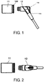
FIG. 1 is a main view of the present invention. -
FIG. 2 is a top view of the present invention. -
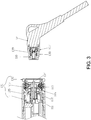
FIG. 3 is a cross-sectional view of the present invention. - The present invention will be further described below based on the drawings and specific embodiments, but embodiments of the present invention are not limited thereto.
- As shown in
FIG. 1, FIG. 2 andFIG. 3 , a detachable power cord structure for a portable hair curler includes adevice tail sleeve 11 and atail wire 12. An elasticengaging assembly 101 is arranged in thedevice tail sleeve 11. Thetail wire 12 is inserted into thedevice tail sleeve 11 and is engaged with the elasticengaging assembly 101. When thetail wire 12 is engaged into the elasticengaging assembly 101, it can turn on the circuit and can be rotated freely. - Preferably, the elastic
engaging assembly 101 includes atail spring ring 102. One end of thetail spring ring 102 extending into thedevice tail sleeve 11 is provided with abuckle 103. The inside of thebuckle 103 is provided with aprotrusion 104, and aspring groove 105 is disposed on the inner side wall of thedevice tail sleeve 11. Atail spring 106 is disposed in thespring groove 105. Thetail spring ring 102 extends into thedevice tail sleeve 11 and abuts against thetail spring 106. - Preferably, the
tail wire 12 has aninsertion end 107. The outer side of theinsertion end 107 is provided with anannular groove 108. The axial center of theinsertion end 107 is provided with apositive insertion port 109, and theinsertion end 107 is further provided with an annularnegative insertion slot 110 therein. Theprotrusion 104 of thebuckle 103 is docked with theannular groove 108. - Preferably, the
device tail sleeve 11 is further provided with asocket terminal 111. Thesocket terminal 111 is provided with apositive contact pin 112 and an annularnegative contact piece 113. Thepositive contact pin 112 is inserted into thepositive insertion port 109 in an aligned manner, and the annularnegative contact piece 113 is docked with the annularnegative insertion slot 110. Thesocket terminal 111 is electrically connected to a PCB board 5. - Preferably, when the
tail spring ring 102 is pushed to press thetail spring 106, thebuckle 103 moves along with thetail spring ring 102 and is detached from thetail wire 12. - Preferably, the annular
negative insertion slot 110 is provided with a power negative contact terminal, and thepositive insertion port 109 is provided with a power positive contact terminal therein. - Preferably, the power negative contact terminal is disposed around the annular
negative insertion slot 110. When the annularnegative insertion slot 110 is docked with the contact terminal of the hairdressing appliance, the power negative contact terminal can completely contact the terminal to ensure electrical connection. The annularnegative insertion slot 110 has a certain insertion and positioning function. - Preferably, the other end of the
tail wire 12 is a power cord buried end 114, and an angle greater than 90 degrees is formed between the power cord buried end 114 and theinsertion end 107. - Preferably, a side of the power cord buried
end 114 is provided with a hanginghole 115. Thehanging hole 115 facilitates the hanging of the power connector and makes it easy for the worker to pick and place. - Preferably, the power cord buried end 114 and the
insertion end 107 are integrally formed by injection molding. The power positive contact terminal and the power negative contact terminal are all hidden in the tail wire, and the safety performance is higher. - The power connector structure adopted by the present invention can be rotated through insertion of the device tail sleeve and the tail wire. An elastic engaging assembly is arranged in the device tail sleeve, the tail wire is inserted into the device tail sleeve and is engaged with the elastic engaging assembly. When the tail wire is engaged into the elastic engaging assembly, it can turn on the circuit and can be rotated freely. When the tail wire is electrically connected, it can be rotated freely without bending or curing during use, thereby effectively ensuring the service life of the tail wire.
Claims (10)
- A detachable power cord structure for a portable hair curler, comprising a device tail sleeve (11) and a tail wire (12), wherein the device tail sleeve (11) is provided with an elastic engaging assembly (101), and the tail wire (12) is inserted into the device tail sleeve (11), and is engaged with the elastic engaging assembly (101), when the tail wire (12) is engaged in the elastic engaging assembly (101) and can turn on a circuit and can be rotated freely.
- The detachable power cord structure for the portable hair curler according to claim 1, wherein the elastic engaging assembly (101) comprises a tail spring ring (102), and one end of the tail spring ring (102) extending into the device tail sleeve (11) is provided with a buckle (103), a protrusion (104) is arranged on an inner side of the buckle (103), a spring groove (105) is arranged on an inner side wall of the device tail sleeve (11), and a tail spring (106) is arranged in the spring groove (105), and the tail spring ring (102) extends into the device tail sleeve (11) and abuts against the tail spring (106).
- The detachable power cord structure for the portable hair curler according to claim 2, wherein the tail wire (12) has an insertion end (107), and an outer side of the insertion end (107) is provided with an annular groove (108), an axial center of the insertion end (107) is provided with a positive insertion port (109), and an annular negative insertion slot (110) is further provided in the insertion end (107), and a protrusion (104) of the buckle is docked with the annular groove (108).
- The detachable power cord structure for the portable hair curler according to claim 3, wherein the device tail sleeve (11) is further provided with a socket terminal (111), and the socket terminal (111) is provided with a positive contact pin (112) and an annular negative contact piece (113), the positive contact pin (112) is inserted into the positive insertion port (109) in an aligned manner, and the annular negative contact piece (113) is docked with the annular negative insertion slot (110).
- The detachable power cord structure for the portable hair curler according to claim 4, wherein when the tail spring ring (102) is pushed to press the tail spring (106), the buckle moves along with the tail spring ring (102) and is detached from the tail wire (12).
- The detachable power cord structure for the portable hair curler according to claim 4, wherein the annular negative insertion slot (110) is provided with a power negative contact terminal therein, and the positive insertion port (109) is provided with a power positive contact terminal therein.
- The detachable power cord structure for the portable hair curler according to claim 6, wherein the power negative contact terminal is disposed around the annular negative insertion slot (110).
- The detachable power cord structure for the portable hair curler according to claim 4, wherein the other end of the tail wire (12) is a power cord buried end (114), and an angle greater than 90 degrees is formed between the power cord buried end (114) and insertion end (107).
- The detachable power cord structure for the portable hair curler according to claim 8, wherein a side of the power cord buried end (114) is provided with a hanging hole (115).
- The detachable power cord structure for the portable hair curler according to claim 8, wherein the power cord buried end (114) and the insertion end (107) are integrally injection molded.
Applications Claiming Priority (1)
| Application Number | Priority Date | Filing Date | Title |
|---|---|---|---|
| CN201910828380.0A CN110444976B (en) | 2019-09-03 | 2019-09-03 | Detachable structure of power line of portable hair curler |
Publications (3)
| Publication Number | Publication Date |
|---|---|
| EP3790128A1 true EP3790128A1 (en) | 2021-03-10 |
| EP3790128C0 EP3790128C0 (en) | 2025-01-01 |
| EP3790128B1 EP3790128B1 (en) | 2025-01-01 |
Family
ID=68438938
Family Applications (1)
| Application Number | Title | Priority Date | Filing Date |
|---|---|---|---|
| EP20151723.2A Active EP3790128B1 (en) | 2019-09-03 | 2020-01-14 | Detachable power cord structure for portable hair curler |
Country Status (6)
| Country | Link |
|---|---|
| US (1) | US10944195B1 (en) |
| EP (1) | EP3790128B1 (en) |
| JP (1) | JP6913190B2 (en) |
| KR (1) | KR102304394B1 (en) |
| CN (1) | CN110444976B (en) |
| GB (1) | GB2586896B (en) |
Families Citing this family (11)
| Publication number | Priority date | Publication date | Assignee | Title |
|---|---|---|---|---|
| US11259612B2 (en) | 2019-09-03 | 2022-03-01 | Dongguan Lisi Intelligent Technology Co., Ltd | Power cord detachable structure for portable hair curler |
| CN111109807A (en) * | 2020-02-24 | 2020-05-08 | 东莞丽丝智能科技有限公司 | Portable electric heating comb |
| CN213399237U (en) * | 2020-12-09 | 2021-06-08 | 东莞富美康电器科技有限公司 | Power supply tail wire connecting and fixing structure and hairstyle processor |
| CN112821136A (en) * | 2021-02-05 | 2021-05-18 | 东莞丽丝智能科技有限公司 | Power line quick assembly disassembly structure of portable curler |
| CN112769000B (en) * | 2021-02-05 | 2025-01-28 | 广东丽丝智能科技有限公司 | A convenient detachable structure for the power cord of a portable hair curler |
| CN112821141A (en) * | 2021-02-05 | 2021-05-18 | 东莞丽丝智能科技有限公司 | Power line reinforced detachable structure of portable hair curler |
| EP4040607A1 (en) * | 2021-02-08 | 2022-08-10 | Dongguan Lisi Intelligent Technology Co., Ltd. | Power cord detachable structure for portable hair curler |
| CN115245234A (en) * | 2021-04-25 | 2022-10-28 | 黑蜂智造(深圳)科技有限公司 | Functional comb |
| DE102021204368A1 (en) | 2021-04-30 | 2022-11-03 | Robert Bosch Gesellschaft mit beschränkter Haftung | Steering device with a connector unit |
| USD1028879S1 (en) * | 2022-03-10 | 2024-05-28 | Japan Aviation Electronics Industry, Limited | Charge connector |
| CN115886418A (en) * | 2022-12-14 | 2023-04-04 | 东莞意象工业设计有限公司 | A hair dryer structure with detachable power cord |
Citations (2)
| Publication number | Priority date | Publication date | Assignee | Title |
|---|---|---|---|---|
| US7481673B1 (en) * | 2008-05-07 | 2009-01-27 | Jinliang Qu | Airtight RF coaxial connector with self-locking by snap-fastening |
| CN206714345U (en) * | 2017-04-25 | 2017-12-08 | 赵永鹏 | The clutch and anti-scald curler of a kind of anti-scald curler |
Family Cites Families (30)
| Publication number | Priority date | Publication date | Assignee | Title |
|---|---|---|---|---|
| US3843224A (en) * | 1972-12-21 | 1974-10-22 | Black & Decker Mfg Co | Detachable cord set for electric device |
| JP3346846B2 (en) * | 1993-08-26 | 2002-11-18 | 松下電工株式会社 | Connector structure of photoelectric sensor |
| US5409403A (en) * | 1993-10-25 | 1995-04-25 | Falossi; Aldo | 360 degree connector system |
| US5399093A (en) * | 1994-02-01 | 1995-03-21 | Woods Industries, Inc. | Low profile rotatable electrical plug |
| US5595503A (en) * | 1995-06-07 | 1997-01-21 | Woods Industries, Inc. | Rotatable electrical plug and power cord |
| DE69611019T2 (en) * | 1995-08-09 | 2001-06-21 | Sumitomo Wiring Systems, Ltd. | Locking arrangement for connectors and its use for charging connectors and / or high voltage connectors |
| KR200224643Y1 (en) * | 2000-10-19 | 2001-05-15 | 김금자 | Cosmetic apparatus |
| US6793499B1 (en) * | 2003-08-05 | 2004-09-21 | Tsang-I Chen | Rotatable electrical plug |
| JP4020885B2 (en) * | 2004-04-27 | 2007-12-12 | ヒロセ電機株式会社 | Card connector and card contact terminal used therefor |
| KR200391258Y1 (en) * | 2005-05-06 | 2005-08-02 | 유니텍(주) | Twisted protect device the telephone line of the handset |
| US7186133B1 (en) * | 2005-08-31 | 2007-03-06 | Tyco Electronics Corporation | Connector with rotatable cable exit |
| SE530669C2 (en) * | 2006-03-20 | 2008-08-05 | Atlas Copco Tools Ab | Electric power tool with swivel cable connection |
| KR100644145B1 (en) * | 2006-03-22 | 2006-11-13 | (주)신우굿아이템 | Detachable anti-twist cord and electronics with it |
| US7234963B1 (en) * | 2006-11-08 | 2007-06-26 | Kui-Hsien Huang | USB connector with orientation adjustment |
| US7566223B2 (en) * | 2007-04-20 | 2009-07-28 | Belkin International, Inc. | Electrical connector and method of manufacturing same |
| US7946852B2 (en) * | 2007-04-20 | 2011-05-24 | Belkin Intenational, Inc. | Electrical connector and method of manufacturing same |
| US7914292B2 (en) * | 2008-10-16 | 2011-03-29 | Belkin International, Inc. | Electric plug and method of providing the same |
| CN201528775U (en) * | 2009-09-04 | 2010-07-21 | 东莞富美康电器科技有限公司 | Hair curling rod connector |
| KR101122362B1 (en) * | 2010-06-24 | 2012-03-23 | 이승국 | beauty apparatus having detachable rotate-code |
| WO2012111898A1 (en) * | 2011-02-18 | 2012-08-23 | Lee Seung-Soo | Hair iron |
| KR200478518Y1 (en) * | 2011-07-04 | 2015-10-14 | 이승수 | A hair iron having structure for preventing easy disassembling |
| US8968023B1 (en) * | 2013-08-08 | 2015-03-03 | Williamsrdm, Inc. | Rotatable wiring harness for cable and method |
| US9257758B2 (en) * | 2014-05-26 | 2016-02-09 | Nudl Innovations, Llc | Integrated cord tie and signal conducting device |
| CN106936008A (en) * | 2015-12-31 | 2017-07-07 | 上海航天科工电器研究院有限公司 | A kind of radio frequency coaxial electric connector with fast locking device |
| KR101828816B1 (en) * | 2016-03-17 | 2018-02-14 | 길인송 | Connector of electric hair styling device |
| CN207613366U (en) * | 2017-10-30 | 2018-07-17 | 惠州市深创实业有限公司 | A kind of curler |
| CN207638045U (en) * | 2017-11-17 | 2018-07-20 | 新加坡大华集团 | Pin connector, socket connector and combinations thereof, power cord and handheld apparatus |
| CN108777398B (en) * | 2018-05-31 | 2023-11-14 | 黄广文 | Self-locking pneumatic power-on ventilation female head and male head matched with same |
| CN110311246B (en) * | 2019-07-05 | 2024-06-25 | 广州番禺电缆集团有限公司 | Joint device |
| CN210224528U (en) * | 2019-09-03 | 2020-03-31 | 东莞丽丝智能科技有限公司 | Electric switching structure for hair curler, hair curler or hair straightener and hair curler |
-
2019
- 2019-09-03 CN CN201910828380.0A patent/CN110444976B/en active Active
- 2019-10-17 US US16/655,278 patent/US10944195B1/en active Active
-
2020
- 2020-01-09 GB GB2000320.8A patent/GB2586896B/en not_active Expired - Fee Related
- 2020-01-14 EP EP20151723.2A patent/EP3790128B1/en active Active
- 2020-01-16 JP JP2020005432A patent/JP6913190B2/en active Active
- 2020-01-20 KR KR1020200007349A patent/KR102304394B1/en active Active
Patent Citations (2)
| Publication number | Priority date | Publication date | Assignee | Title |
|---|---|---|---|---|
| US7481673B1 (en) * | 2008-05-07 | 2009-01-27 | Jinliang Qu | Airtight RF coaxial connector with self-locking by snap-fastening |
| CN206714345U (en) * | 2017-04-25 | 2017-12-08 | 赵永鹏 | The clutch and anti-scald curler of a kind of anti-scald curler |
Also Published As
| Publication number | Publication date |
|---|---|
| US10944195B1 (en) | 2021-03-09 |
| JP2021039931A (en) | 2021-03-11 |
| KR20210028051A (en) | 2021-03-11 |
| EP3790128C0 (en) | 2025-01-01 |
| GB2586896B (en) | 2022-05-25 |
| GB202000320D0 (en) | 2020-02-26 |
| EP3790128B1 (en) | 2025-01-01 |
| CN110444976A (en) | 2019-11-12 |
| CN110444976B (en) | 2024-10-29 |
| US20210066837A1 (en) | 2021-03-04 |
| JP6913190B2 (en) | 2021-08-04 |
| GB2586896A (en) | 2021-03-10 |
| KR102304394B1 (en) | 2021-09-23 |
Similar Documents
| Publication | Publication Date | Title |
|---|---|---|
| US10944195B1 (en) | Detachable power cord structure for portable hair curler | |
| US9444205B2 (en) | Electric connector with contact protection | |
| PH12018000416B1 (en) | Hub apparatus and associated charging apparatus and systems | |
| US20030203682A1 (en) | Secured connector and using process thereof | |
| US7001199B1 (en) | Electrical connection | |
| CN204316152U (en) | Plug-type charger | |
| CN102157832B (en) | Line connector | |
| US2340703A (en) | Metal strain relief | |
| KR20190119747A (en) | Electrical plug for charging portable terminal | |
| CN205488680U (en) | An Improved D-SUB Socket | |
| CN207800975U (en) | Anti-shock plug | |
| KR101697125B1 (en) | USB charger | |
| CN210959115U (en) | Electronic device | |
| KR20140005695A (en) | Plug for charger | |
| CN109980405A (en) | Anti-shock plug | |
| US20210161269A1 (en) | Novel power cord detachable structure for portable hair curler | |
| KR101198145B1 (en) | Power plug | |
| CN211795268U (en) | Quick-connection type integral cabinet | |
| CN210111228U (en) | Converter | |
| CN215377853U (en) | Separable data line with fixed buckle | |
| CN208806407U (en) | A kind of power connector | |
| CN212136325U (en) | Wall socket with charging connection | |
| CN207474825U (en) | A plug-free cut-off power cord | |
| CN107910660B (en) | A kind of rapid wiring device and electrical accessorie | |
| KR101185347B1 (en) | Outlet damage prevention for electric plug |
Legal Events
| Date | Code | Title | Description |
|---|---|---|---|
| PUAI | Public reference made under article 153(3) epc to a published international application that has entered the european phase |
Free format text: ORIGINAL CODE: 0009012 |
|
| STAA | Information on the status of an ep patent application or granted ep patent |
Free format text: STATUS: REQUEST FOR EXAMINATION WAS MADE |
|
| 17P | Request for examination filed |
Effective date: 20200115 |
|
| AK | Designated contracting states |
Kind code of ref document: A1 Designated state(s): AL AT BE BG CH CY CZ DE DK EE ES FI FR GB GR HR HU IE IS IT LI LT LU LV MC MK MT NL NO PL PT RO RS SE SI SK SM TR |
|
| AX | Request for extension of the european patent |
Extension state: BA ME |
|
| RBV | Designated contracting states (corrected) |
Designated state(s): AL AT BE BG CH CY CZ DE DK EE ES FI FR GB GR HR HU IE IS IT LI LT LU LV MC MK MT NL NO PL PT RO RS SE SI SK SM TR |
|
| STAA | Information on the status of an ep patent application or granted ep patent |
Free format text: STATUS: EXAMINATION IS IN PROGRESS |
|
| 17Q | First examination report despatched |
Effective date: 20220513 |
|
| GRAP | Despatch of communication of intention to grant a patent |
Free format text: ORIGINAL CODE: EPIDOSNIGR1 |
|
| STAA | Information on the status of an ep patent application or granted ep patent |
Free format text: STATUS: GRANT OF PATENT IS INTENDED |
|
| INTG | Intention to grant announced |
Effective date: 20240802 |
|
| GRAS | Grant fee paid |
Free format text: ORIGINAL CODE: EPIDOSNIGR3 |
|
| GRAA | (expected) grant |
Free format text: ORIGINAL CODE: 0009210 |
|
| STAA | Information on the status of an ep patent application or granted ep patent |
Free format text: STATUS: THE PATENT HAS BEEN GRANTED |
|
| RAP1 | Party data changed (applicant data changed or rights of an application transferred) |
Owner name: GUANGDONG LISI INTELLIGENT TECHNOLOGY CO., LTD |
|
| AK | Designated contracting states |
Kind code of ref document: B1 Designated state(s): AL AT BE BG CH CY CZ DE DK EE ES FI FR GB GR HR HU IE IS IT LI LT LU LV MC MK MT NL NO PL PT RO RS SE SI SK SM TR |
|
| REG | Reference to a national code |
Ref country code: GB Ref legal event code: FG4D |
|
| REG | Reference to a national code |
Ref country code: DE Ref legal event code: R096 Ref document number: 602020043906 Country of ref document: DE |
|
| REG | Reference to a national code |
Ref country code: CH Ref legal event code: EP |
|
| REG | Reference to a national code |
Ref country code: IE Ref legal event code: FG4D |
|
| U01 | Request for unitary effect filed |
Effective date: 20250122 |
|
| U07 | Unitary effect registered |
Designated state(s): AT BE BG DE DK EE FI FR IT LT LU LV MT NL PT RO SE SI Effective date: 20250128 |
|
| PG25 | Lapsed in a contracting state [announced via postgrant information from national office to epo] |
Ref country code: PL Free format text: LAPSE BECAUSE OF FAILURE TO SUBMIT A TRANSLATION OF THE DESCRIPTION OR TO PAY THE FEE WITHIN THE PRESCRIBED TIME-LIMIT Effective date: 20250101 |
|
| PG25 | Lapsed in a contracting state [announced via postgrant information from national office to epo] |
Ref country code: ES Free format text: LAPSE BECAUSE OF FAILURE TO SUBMIT A TRANSLATION OF THE DESCRIPTION OR TO PAY THE FEE WITHIN THE PRESCRIBED TIME-LIMIT Effective date: 20250101 |
|
| PG25 | Lapsed in a contracting state [announced via postgrant information from national office to epo] |
Ref country code: IS Free format text: LAPSE BECAUSE OF FAILURE TO SUBMIT A TRANSLATION OF THE DESCRIPTION OR TO PAY THE FEE WITHIN THE PRESCRIBED TIME-LIMIT Effective date: 20250501 Ref country code: NO Free format text: LAPSE BECAUSE OF FAILURE TO SUBMIT A TRANSLATION OF THE DESCRIPTION OR TO PAY THE FEE WITHIN THE PRESCRIBED TIME-LIMIT Effective date: 20250401 |
|
| PG25 | Lapsed in a contracting state [announced via postgrant information from national office to epo] |
Ref country code: HR Free format text: LAPSE BECAUSE OF FAILURE TO SUBMIT A TRANSLATION OF THE DESCRIPTION OR TO PAY THE FEE WITHIN THE PRESCRIBED TIME-LIMIT Effective date: 20250101 |
|
| PG25 | Lapsed in a contracting state [announced via postgrant information from national office to epo] |
Ref country code: GR Free format text: LAPSE BECAUSE OF FAILURE TO SUBMIT A TRANSLATION OF THE DESCRIPTION OR TO PAY THE FEE WITHIN THE PRESCRIBED TIME-LIMIT Effective date: 20250402 |
|
| PG25 | Lapsed in a contracting state [announced via postgrant information from national office to epo] |
Ref country code: CZ Free format text: LAPSE BECAUSE OF FAILURE TO SUBMIT A TRANSLATION OF THE DESCRIPTION OR TO PAY THE FEE WITHIN THE PRESCRIBED TIME-LIMIT Effective date: 20250101 |
|
| REG | Reference to a national code |
Ref country code: CH Ref legal event code: PL |
|
| U21 | Renewal fee for the european patent with unitary effect paid with additional fee |
Year of fee payment: 6 Effective date: 20250731 |
|
| PG25 | Lapsed in a contracting state [announced via postgrant information from national office to epo] |
Ref country code: SM Free format text: LAPSE BECAUSE OF FAILURE TO SUBMIT A TRANSLATION OF THE DESCRIPTION OR TO PAY THE FEE WITHIN THE PRESCRIBED TIME-LIMIT Effective date: 20250101 |
|
| PG25 | Lapsed in a contracting state [announced via postgrant information from national office to epo] |
Ref country code: MC Free format text: LAPSE BECAUSE OF FAILURE TO SUBMIT A TRANSLATION OF THE DESCRIPTION OR TO PAY THE FEE WITHIN THE PRESCRIBED TIME-LIMIT Effective date: 20250101 |
|
| PG25 | Lapsed in a contracting state [announced via postgrant information from national office to epo] |
Ref country code: CH Free format text: LAPSE BECAUSE OF NON-PAYMENT OF DUE FEES Effective date: 20250131 |
|
| PG25 | Lapsed in a contracting state [announced via postgrant information from national office to epo] |
Ref country code: SK Free format text: LAPSE BECAUSE OF FAILURE TO SUBMIT A TRANSLATION OF THE DESCRIPTION OR TO PAY THE FEE WITHIN THE PRESCRIBED TIME-LIMIT Effective date: 20250101 |
|
| PLBE | No opposition filed within time limit |
Free format text: ORIGINAL CODE: 0009261 |
|
| STAA | Information on the status of an ep patent application or granted ep patent |
Free format text: STATUS: NO OPPOSITION FILED WITHIN TIME LIMIT |
|
| U1N | Appointed representative for the unitary patent procedure changed after the registration of the unitary effect |
Representative=s name: SANTARELLI; FR |
|
| 26N | No opposition filed |
Effective date: 20251002 |
|
| GBPC | Gb: european patent ceased through non-payment of renewal fee |
Effective date: 20250401 |
|
| PG25 | Lapsed in a contracting state [announced via postgrant information from national office to epo] |
Ref country code: GB Free format text: LAPSE BECAUSE OF NON-PAYMENT OF DUE FEES Effective date: 20250401 |
|
| PG25 | Lapsed in a contracting state [announced via postgrant information from national office to epo] |
Ref country code: IE Free format text: LAPSE BECAUSE OF NON-PAYMENT OF DUE FEES Effective date: 20250114 |