EP3790116A1 - Connector and connector manufacturing method - Google Patents
Connector and connector manufacturing method Download PDFInfo
- Publication number
- EP3790116A1 EP3790116A1 EP20188398.0A EP20188398A EP3790116A1 EP 3790116 A1 EP3790116 A1 EP 3790116A1 EP 20188398 A EP20188398 A EP 20188398A EP 3790116 A1 EP3790116 A1 EP 3790116A1
- Authority
- EP
- European Patent Office
- Prior art keywords
- contact
- contacts
- connector
- receptacle
- arrays
- Prior art date
- Legal status (The legal status is an assumption and is not a legal conclusion. Google has not performed a legal analysis and makes no representation as to the accuracy of the status listed.)
- Granted
Links
Images





Classifications
-
- H—ELECTRICITY
- H01—ELECTRIC ELEMENTS
- H01R—ELECTRICALLY-CONDUCTIVE CONNECTIONS; STRUCTURAL ASSOCIATIONS OF A PLURALITY OF MUTUALLY-INSULATED ELECTRICAL CONNECTING ELEMENTS; COUPLING DEVICES; CURRENT COLLECTORS
- H01R13/00—Details of coupling devices of the kinds covered by groups H01R12/70 or H01R24/00 - H01R33/00
- H01R13/40—Securing contact members in or to a base or case; Insulating of contact members
- H01R13/405—Securing in non-demountable manner, e.g. moulding, riveting
- H01R13/41—Securing in non-demountable manner, e.g. moulding, riveting by frictional grip in grommet, panel or base
-
- H—ELECTRICITY
- H01—ELECTRIC ELEMENTS
- H01R—ELECTRICALLY-CONDUCTIVE CONNECTIONS; STRUCTURAL ASSOCIATIONS OF A PLURALITY OF MUTUALLY-INSULATED ELECTRICAL CONNECTING ELEMENTS; COUPLING DEVICES; CURRENT COLLECTORS
- H01R13/00—Details of coupling devices of the kinds covered by groups H01R12/70 or H01R24/00 - H01R33/00
- H01R13/40—Securing contact members in or to a base or case; Insulating of contact members
- H01R13/42—Securing in a demountable manner
-
- H—ELECTRICITY
- H01—ELECTRIC ELEMENTS
- H01R—ELECTRICALLY-CONDUCTIVE CONNECTIONS; STRUCTURAL ASSOCIATIONS OF A PLURALITY OF MUTUALLY-INSULATED ELECTRICAL CONNECTING ELEMENTS; COUPLING DEVICES; CURRENT COLLECTORS
- H01R12/00—Structural associations of a plurality of mutually-insulated electrical connecting elements, specially adapted for printed circuits, e.g. printed circuit boards [PCB], flat or ribbon cables, or like generally planar structures, e.g. terminal strips, terminal blocks; Coupling devices specially adapted for printed circuits, flat or ribbon cables, or like generally planar structures; Terminals specially adapted for contact with, or insertion into, printed circuits, flat or ribbon cables, or like generally planar structures
- H01R12/70—Coupling devices
- H01R12/71—Coupling devices for rigid printing circuits or like structures
- H01R12/712—Coupling devices for rigid printing circuits or like structures co-operating with the surface of the printed circuit or with a coupling device exclusively provided on the surface of the printed circuit
- H01R12/716—Coupling device provided on the PCB
-
- H—ELECTRICITY
- H01—ELECTRIC ELEMENTS
- H01R—ELECTRICALLY-CONDUCTIVE CONNECTIONS; STRUCTURAL ASSOCIATIONS OF A PLURALITY OF MUTUALLY-INSULATED ELECTRICAL CONNECTING ELEMENTS; COUPLING DEVICES; CURRENT COLLECTORS
- H01R43/00—Apparatus or processes specially adapted for manufacturing, assembling, maintaining, or repairing of line connectors or current collectors or for joining electric conductors
- H01R43/20—Apparatus or processes specially adapted for manufacturing, assembling, maintaining, or repairing of line connectors or current collectors or for joining electric conductors for assembling or disassembling contact members with insulating base, case or sleeve
-
- H—ELECTRICITY
- H01—ELECTRIC ELEMENTS
- H01R—ELECTRICALLY-CONDUCTIVE CONNECTIONS; STRUCTURAL ASSOCIATIONS OF A PLURALITY OF MUTUALLY-INSULATED ELECTRICAL CONNECTING ELEMENTS; COUPLING DEVICES; CURRENT COLLECTORS
- H01R43/00—Apparatus or processes specially adapted for manufacturing, assembling, maintaining, or repairing of line connectors or current collectors or for joining electric conductors
- H01R43/20—Apparatus or processes specially adapted for manufacturing, assembling, maintaining, or repairing of line connectors or current collectors or for joining electric conductors for assembling or disassembling contact members with insulating base, case or sleeve
- H01R43/205—Apparatus or processes specially adapted for manufacturing, assembling, maintaining, or repairing of line connectors or current collectors or for joining electric conductors for assembling or disassembling contact members with insulating base, case or sleeve with a panel or printed circuit board
-
- H—ELECTRICITY
- H01—ELECTRIC ELEMENTS
- H01R—ELECTRICALLY-CONDUCTIVE CONNECTIONS; STRUCTURAL ASSOCIATIONS OF A PLURALITY OF MUTUALLY-INSULATED ELECTRICAL CONNECTING ELEMENTS; COUPLING DEVICES; CURRENT COLLECTORS
- H01R12/00—Structural associations of a plurality of mutually-insulated electrical connecting elements, specially adapted for printed circuits, e.g. printed circuit boards [PCB], flat or ribbon cables, or like generally planar structures, e.g. terminal strips, terminal blocks; Coupling devices specially adapted for printed circuits, flat or ribbon cables, or like generally planar structures; Terminals specially adapted for contact with, or insertion into, printed circuits, flat or ribbon cables, or like generally planar structures
- H01R12/50—Fixed connections
- H01R12/51—Fixed connections for rigid printed circuits or like structures
- H01R12/55—Fixed connections for rigid printed circuits or like structures characterised by the terminals
- H01R12/57—Fixed connections for rigid printed circuits or like structures characterised by the terminals surface mounting terminals
-
- H—ELECTRICITY
- H01—ELECTRIC ELEMENTS
- H01R—ELECTRICALLY-CONDUCTIVE CONNECTIONS; STRUCTURAL ASSOCIATIONS OF A PLURALITY OF MUTUALLY-INSULATED ELECTRICAL CONNECTING ELEMENTS; COUPLING DEVICES; CURRENT COLLECTORS
- H01R13/00—Details of coupling devices of the kinds covered by groups H01R12/70 or H01R24/00 - H01R33/00
- H01R13/02—Contact members
- H01R13/10—Sockets for co-operation with pins or blades
- H01R13/11—Resilient sockets
- H01R13/115—U-shaped sockets having inwardly bent legs, e.g. spade type
Definitions
- the present invention relates to a connector, particularly to a connector mounted on a mounting object and connected to a counter connector.
- the present invention also relates to a method of manufacturing such a connector.
- JP 2017-84736 A discloses a receptacle connector 1 and a plug connector 2 both of which have a substantially flat plate shape, as shown in FIG. 27 .
- the receptacle connector 1 has a plurality of receptacle contacts 4 press-fitted in and retained by a receptacle housing 3 of flat plate shape
- the plug connector 2 has a plurality of plug contacts 6 press-fitted in and retained by a plug housing 5 of flat plate shape.
- the receptacle contacts 4 form four contact arrays 7 linearly extending in parallel to each other
- the plug contacts 6 form four contact arrays 8 linearly extending in parallel to each other so as to correspond to the four contact arrays 7 of the receptacle connector 1.
- FIG. 28 is a cross-sectional view cut along a plane orthogonal to the direction in which the contact arrays 7 and 8 extend.
- each contact array 7 has plural receptacle contacts 4
- receptacle contacts 4 constituting one contact array 7 can be press-fitted together into the receptacle housing 3 while being joined to a single carrier, and then, the carrier can be separated from the receptacle contacts 4 at a time by means of a carrier cutting tool.
- a step involving collective press-fitting of plural receptacle contacts 4 joined to a carrier and collective separation thereof is repeated four times to manufacture the receptacle connector 1 having the four contact arrays 7.
- each contact array 8 On the basis of each contact array 8, collective press-fitting of plural plug contacts 6 joined to a carrier and collective separation thereof are serially carried out, thus manufacturing the plug connector 2 having the four contact arrays 8 in the same manner as that for the receptacle connector 1.
- the receptacle contacts 4 constituting the four contact arrays 7 are disposed to coincide each other in the direction perpendicular to the contact arrays 7; similarly, in the plug connector 2, the plug contacts 6 constituting the four contact arrays 8 are disposed to coincide each other in the direction perpendicular to the contact arrays 8.
- the present invention has been made to solve the conventional problem described above and is aimed at providing a connector that allows facilitation of its manufacturing process despite that the connector has a large number of contacts.
- the present invention is also aimed at providing a method of manufacturing such a connector.
- a connector according to the present invention is a connector mounted on a mounting object and connected to a counter connector, the connector comprising:
- a method of manufacturing a connector according to the present invention comprises:
- FIG. 1 shows a receptacle connector (connector) 11 and a plug connector (connector) 21 according to the embodiment before the connectors 11 and 21 are fitted to each other.
- the receptacle connector 11 and the plug connector 21 constitute a connector assembly, each have a substantially rectangular flat plate shape, and are arranged in parallel to each other.
- the receptacle connector 11 has a receptacle housing (housing) 31 and a plurality of receptacle contacts (contacts) 41 retained by the receptacle housing 31.
- the receptacle contacts 41 form four contact arrays S1 to S4 linearly extending in a predetermined array direction in parallel to each other.
- the plug connector 21 has a plug housing (housing) 51 and a plurality of plug contacts (contacts) 61 retained by the plug housing 51.
- the plug contacts 61 form four contact arrays T1 to T4 linearly extending in the same array direction as that of the contact arrays S1 to S4 of the receptacle connector 11 in parallel to each other.
- the contact arrays S1 to S4 of the receptacle connector 11 and the contact arrays T1 to T4 of the plug connector 21 extend in the same direction.
- the receptacle contacts 41 in the contact arrays S1 to S4 of the receptacle connector 11 are correspondingly connected to the plug contacts 61 in the contact arrays T1 to T4 of the plug connector 21.
- the plane in which the receptacle connector 11 of substantially flat plate shape extends is called “XY plane,” the predetermined array direction in which the contact arrays S1 to S4 of the receptacle connector 11 extend “Y direction,” the direction in which the contact arrays S1 to S4 are arranged “X direction,” and the direction perpendicular to an XY plane and from the receptacle connector 11 toward the plug connector 21 "+Z direction.”
- the plug connector 21 extends along an XY plane, the contact arrays T1 to T4 of the plug connector 21 extend in the Y direction, and the contact arrays T1 to T4 are arranged in the X direction.
- the receptacle connector 11 is able to fit with the plug connector 21 serving as a counter connector, and as shown in FIGS. 2 to 4 , has a center line C1 extending in the Y direction.
- the contact arrays S1 and S2 are disposed on the +X direction side of the center line C1
- the contact arrays S3 and S4 are disposed on the -X direction side of the center line C1.
- the receptacle housing 31 of the receptacle connector 11 is made of an insulating body such as insulating resin, has a substantially flat plate shape, and includes a flat surface portion 32 extending along an XY plane on the -Z side of the receptacle housing 31.
- a peripheral wall portion 33 protruding in the +Z direction is formed along the outer periphery of the flat surface portion 32, and three projecting portions 34 are formed in the area surrounded by the peripheral wall portion 33 and project in the +Z direction from the flat surface portion 32 while extending in the Y direction in parallel to each other.
- the three projecting portions 34 have the same length in the Y direction, and one projecting portion 34 situated in the middle in the X direction is wider in the X direction than each of the projecting portions 34 situated in the opposite sides in the X direction.
- the receptacle housing 31 has four contact array retaining portions 35 disposed separately on the +X direction side of, among the three projecting portions 34, the projecting portion 34 furthest on the +X direction side, on the +X direction side and the -X direction side of the projecting portion 34 situated in the middle in the X direction, and on the -X direction side of the projecting portion 34 furthest on the -X direction side.
- the four contact array retaining portions 35 extend in the Y direction and separately retain the contact arrays S1 to S4.
- an opening portion 36A extending in the Y direction and penetrating the receptacle housing 31 in the Z direction is formed between the contact array retaining portion 35 disposed on the +X direction side of the projecting portion 34 situated in the middle in the X direction and the projecting portion 34 furthest on the +X direction side.
- an opening portion 36B extending in the Y direction and penetrating the receptacle housing 31 in the Z direction is formed between the contact array retaining portion 35 disposed on the -X direction side of the projecting portion 34 situated in the middle in the X direction and the projecting portion 34 furthest on the -X direction side.
- Two positioning recess portions 37 are formed in the peripheral wall portion 33 at the +Y directional end of the receptacle housing 31 at a certain interval in the X direction to open in the +Z direction, while one positioning recess portion 37 is formed in the peripheral wall portion 33 at the -Y directional end of the receptacle housing 31 to open in the +Z direction.
- each contact array retaining portion 35 has a plurality of contact accommodating grooves 38 aligned in the Y direction.
- Each contact accommodating groove 38 extends in the X direction and opens in the -Z direction.
- the contact accommodating groove 38 is provided in its inside with a pair of projections 38A that project separately from the inner surfaces on the +Y and -Y direction sides of the contact accommodating groove 38 such that the tips of the projections 38A face each other.
- Those projections 38A and an X directional end of the contact accommodating groove 38 constitute a retaining portion 38B for retaining the corresponding receptacle contact 41.
- the receptacle contact 41 is formed by bending a band-shaped metal plate having electrical conductivity, and has a mounting portion 41A at its one end and a contact portion 41B at its other end.
- the mounting portion 41A extends along an XY plane and, when the receptacle connector 11 is mounted onto a mounting object such as a circuit board, is joined and fixed to a connecting pad or the like of the mounting object.
- the contact portion 41B is a spring contact that is elastically displaceable in the X direction and when the receptacle connector 11 is connected to the plug connector 21 serving as the counter connector, comes into contact with the corresponding plug contact 61 of the plug connector 21.
- the receptacle contact 41 further has a portion to be retained 41C between the mounting portion 41A and the contact portion 41B.
- the portion to be retained 41C has a pair of jutting portions 41D jutting separately in the +Y direction and the -Y direction from the band-shaped metal plate forming the receptacle contact 41.
- the receptacle contact 41 has a larger width in the Y direction at the pair of jutting portions 41D than that at the other portions, and the width in the Y direction of the receptacle contact 41 at the pair of jutting portions 41D is defined as a contact width W1.
- the receptacle contacts 41 constituting each of the contact arrays S1 to S4 are aligned in the Y direction at a predetermined array pitch P1, and the adjacent contact arrays S1 and S2 are arranged to be offset from each other in the Y direction by an offset amount P2 equal to a half of the array pitch P1.
- the array pitch P1 is set to be larger than a double of the contact width W1 of the receptacle contact 41.
- the offset amount P2 equal to a half of the array pitch P1 is set to be larger than the contact width W1 of the receptacle contact 41.
- the receptacle contacts 41 constituting the contact array S1 and the receptacle contacts 41 constituting the contact array S2 are arranged to be offset from each other in the Y direction by the offset amount P2 and do not overlap each other at all in the X direction perpendicular to the Y direction.
- the adjacent contact arrays S3 and S4 are also arranged to be offset from each other in the Y direction by the offset amount P2.
- the receptacle contacts 41 constituting the contact array S3 and the receptacle contacts 41 constituting the contact array S4 are arranged to be offset from each other in the Y direction by the offset amount P2 and do not overlap each other at all in the X direction perpendicular to the Y direction.
- the contact arrays S1 and S4 are disposed at the same position in the Y direction with no offset, and the contact arrays S2 and S3 are also disposed at the same position in the Y direction with no offset.
- the receptacle connector 11 is cut along an XZ plane passing through given receptacle contacts 41 of the contact arrays S2 and S3, as shown in FIG. 10 , the receptacle contact 41 of the contact array S2 and the receptacle contact 41 of the contact array S3 appear in the cross section, whereas for the contact arrays S1 and S4, no receptacle contact 41 appears in the cross section with only a section of the receptacle housing 31 being seen.
- all of the mounting portions 41A of the receptacle contacts 41 of the adjacent contact arrays S1 and S2 extend in the +X direction, which is an elongation direction, along the flat surface portion 32 of the receptacle housing 31.
- All of the mounting portions 41A of the receptacle contacts 41 of the contact array S1 protrude in the +X direction from the +X directional end of the receptacle housing 31, and all of the mounting portions 41A of the receptacle contacts 41 of the contact array S2 protrude in the opening portion 36A of the receptacle housing 31 that is situated on the +X direction side of the contact array S2.
- all of the mounting portions 41A of the receptacle contacts 41 of the adjacent contact arrays S3 and S4 extend in the -X direction, which is an elongation direction, along an XY plane. All of the mounting portions 41A of the receptacle contacts 41 of the contact array S3 protrude in the opening portion 36B of the receptacle housing 31 that is situated on the - X direction side of the contact array S3, and all of the mounting portions 41A of the receptacle contacts 41 of the contact array S4 protrude in the -X direction from the -X directional end of the receptacle housing 31.
- a method of manufacturing the receptacle connector 11 as above is described.
- the receptacle contacts 41 constituting the contact array S1 and the receptacle contacts 41 constituting the contact array S2 are joined to a single carrier 43A via associated joint portions 42
- the receptacle contacts 41 constituting the contact array S4 and the receptacle contacts 41 constituting the contact array S3 are joined to another single carrier 43B via associated joint portions 42.
- the joint portions 42 connect the mounting portions 41A of the respective receptacle contacts 41 to the corresponding carrier 43A or 43B.
- the receptacle contacts 41 constituting the contact array S1 and the receptacle contacts 41 constituting the contact array S2 are arranged so as not to overlap each other in the X direction. This configuration allows the receptacle contacts 41 constituting the contact array S1 and the receptacle contacts 41 constituting the contact array S2 to be joined to the single carrier 43A.
- the receptacle contacts 41 constituting the contact array S4 and the receptacle contacts 41 constituting the contact array S3 are arranged so as not to overlap each other in the X direction. This configuration allows the receptacle contacts 41 constituting the contact array S4 and the receptacle contacts 41 constituting the contact array S3 to be joined to the other single carrier 43B.
- the receptacle contacts 41 of the contact arrays S1 to S4 are fitted and accommodated into the corresponding contact accommodating grooves 38 of the receptacle housing 31.
- the portion to be retained 41C having the pair of jutting portions 41D shown in FIG. 7 in each receptacle contact 41 is press-fitted into and retained by the retaining portion 38B of the corresponding contact accommodating groove 38 shown in FIG. 6 .
- all of the receptacle contacts 41 of the contact arrays S1 to S4 can be press-fitted together into the receptacle housing 31 by means of the two carriers 43A and 43B in one step.
- the joint portions 42 connecting the receptacle contacts 41 of the contact array S1 to the carrier 43A extend in the +X direction from the +X directional end of the receptacle housing 31, and the joint portions 42 connecting the receptacle contacts 41 of the contact array S2 to the carrier 43A extend across the opening portion 36A of the receptacle housing 31 that is situated on the +X direction side of the contact array S2 and further extend in the +X direction from the +X directional end of the receptacle housing 31.
- joint portions 42 connecting the receptacle contacts 41 of the contact array S4 to the carrier 43B extend from the -X directional end of the receptacle housing 31 toward the -X direction
- the joint portions 42 connecting the receptacle contacts 41 of the contact array S3 to the carrier 43B extend across the opening portion 36B of the receptacle housing 31 that is situated on the -X direction side of the contact array S3 and further extend from the -X directional end of the receptacle housing 31 toward the -X direction.
- each of the four carrier separating tools 44 is a plate member extending along a YZ plane and is provided at its -Z directional end with a blade portion extending along the Y direction.
- the four carrier separating tools 44 are arranged at intervals in the X direction.
- the carrier separating tool 44 situated furthest on the +X direction side is disposed slightly away from the +X directional end of the receptacle housing 31 in the +X direction
- the carrier separating tool 44 situated furthest on the -X direction side is disposed slightly away from the -X directional end of the receptacle housing 31 in the -X direction.
- the carrier separating tool 44 that is the second from the end on the +X direction side is disposed at a position corresponding to the opening portion 36A of the receptacle housing 31 that is situated on the +X direction side of the contact array S2
- the carrier separating tool 44 that is the second from the end on the -X direction side is disposed at a position corresponding to the opening portion 36B of the receptacle housing 31 that is situated on the -X direction side of the contact array S3.
- the four carrier separating tools 44 as above are moved from the +Z direction side toward the -Z direction side, and the blade portions at the -Z directional ends of the carrier separating tools 44 are each pressed to the joint portions 42 of the corresponding carrier 43A or 43B; as a result, the joint portions 42 are cut, and the receptacle contacts 41 are separated from the carrier 43A or 43B.
- the carrier separating tool 44 situated furthest on the +X direction side is moved in the -Z direction along a course slightly away from the +X directional end of the receptacle housing 31 in the +X direction, whereby the receptacle contacts 41 of the contact array S1 are separated from the carrier 43A, and the carrier separating tool 44 that is the second from the end on the +X direction side is moved in the -Z direction through the opening portion 36A of the receptacle housing 31, whereby the receptacle contacts 41 of the contact array S2 are separated from the carrier 43A.
- the receptacle contacts 41 of the contact array S1 and the receptacle contacts 41 of the contact array S2 are joined to the carrier 43A situated on the +X direction side of the receptacle housing 31 via the corresponding joint portions 42, once the joint portions 42 are cut, consequently, the mounting portions 41A of the receptacle contacts 41 of the contact array S1 all extend in the +X direction so as to protrude from the +X directional end of the receptacle housing 31, and the mounting portions 41A of the receptacle contacts 41 of the contact array S2 all extend in the +X direction so as to protrude in the opening portion 36A of the receptacle housing 31.
- the carrier separating tool 44 situated furthest on the -X direction side is moved in the -Z direction along a course slightly away from the -X directional end of the receptacle housing 31 in the -X direction, whereby the receptacle contacts 41 of the contact array S4 are separated from the carrier 43B, and the carrier separating tool 44 that is the second from the end on the -X direction side is moved in the -Z direction through the opening portion 36B of the receptacle housing 31 that is situated on the -X direction side of the contact array S3, whereby the receptacle contacts 41 of the contact array S3 are separated from the carrier 43B.
- the mounting portions 41A of the receptacle contacts 41 of the contact array S4 all extend in the -X direction so as to protrude from the -X directional end of the receptacle housing 31, and the mounting portions 41A of the receptacle contacts 41 of the contact array S3 all extend in the -X direction so as to protrude in the opening portion 36B of the receptacle housing 31.
- all of the receptacle contacts 41 of the contact arrays S1 to S4 can be separated together from the carriers 43A and 43B by means of the four carrier separating tools 44 in one step.
- the foregoing method makes it possible to manufacture the receptacle connector 11 having a large number of receptacle contacts 41 with fewer manufacturing steps.
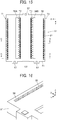
- the plug connector 21 is able to fit with the receptacle connector 11 serving as a counter connector, and as shown in FIGS. 13 to 15 , has a center line C2 extending in the Y direction.
- the contact arrays T1 and T2 are disposed on the +X direction side of the center line C2, and the contact arrays T3 and T4 are disposed on the -X direction side of the center line C2.
- the plug housing 51 of the plug connector 21 is made of an insulating body such as insulating resin, has a substantially flat plate shape, and includes a flat surface portion 52 extending along an XY plane on the +Z side of the plug housing 51.
- a peripheral wall portion 53 protruding in the -Z direction is formed along the outer periphery of the flat surface portion 52, and two partition portions 54A and 54B are formed in the area surrounded by the peripheral wall portion 53 and project in the -Z direction from the flat surface portion 52 while extending in the Y direction in parallel to each other.
- the plug housing 51 has four contact array retaining portions 55 disposed separately on the -X direction side of the +X directional part of the peripheral wall portion 53, on the -X direction side of the partition portion 54A situated on the +X direction side, on the +X direction side of the partition portion 54B situated on the -X direction side, and on the +X direction side of the -X directional part of the peripheral wall portion 53.
- the four contact array retaining portions 55 extend in the Y direction and separately retain the contact arrays T1 to T4.
- an opening portion 56A extending in the Y direction and penetrating the plug housing 51 in the Z direction is formed on the +X direction side of the partition portion 54A situated on the +X direction side
- an opening portion 56B extending in the Y direction and penetrating the plug housing 51 in the Z direction is formed on the -X direction side of the partition portion 54B situated on the -X direction side.
- Two positioning projection portions 57 are formed on the peripheral wall portion 53 at the +Y directional end of the plug housing 51 at a certain interval in the X direction to project in the +Y direction, while one positioning projection portion 57 is formed on the peripheral wall portion 53 at the -Y directional end of the plug housing 51 to project in the +Y direction.
- each contact array retaining portion 55 has a plurality of contact accommodating grooves 58 aligned in the Y direction.
- each contact accommodating groove 58 is provided in its inside with a retaining portion for retaining the corresponding plug contact 61.
- the plug contact 61 is formed by bending a band-shaped metal plate having electrical conductivity, and has a mounting portion 61A at its one end and a contact portion 61B at its other end.
- the mounting portion 61A extends along an XY plane and, when the plug connector 21 is mounted onto a mounting object such as a circuit board, is joined and fixed to a connecting pad or the like of the mounting object.
- the contact portion 61B is a fixed contact that is not elastically displaceable and, when the plug connector 21 is connected to the receptacle connector 11 serving as the counter connector, comes into contact with the corresponding receptacle contact 41 of the receptacle connector 11.
- the plug contact 61 further has a portion to be retained 61C between the mounting portion 61A and the contact portion 61B.
- the portion to be retained 61C has a pair of jutting portions 61D jutting separately in the +Y direction and the -Y direction from the band-shaped metal plate forming the plug contact 61.
- the plug contact 61 has a larger width in the Y direction at the pair of jutting portions 61D than that at the other portions, and the width in the Y direction of the plug contact 61 at the pair of jutting portions 61D is defined as a contact width W2.
- the plug contacts 61 constituting each of the contact arrays T1 to T4 are aligned in the Y direction at the same array pitch P1 as that of the receptacle contacts 41 of the receptacle connector 11, and the adjacent contact arrays T1 and T2 are arranged to be offset from each other in the Y direction by the offset amount P2 equal to a half of the array pitch P1.
- the array pitch P1 is set to be larger than a double of the contact width W2 of the plug contact 61.
- the offset amount P2 equal to a half of the array pitch P1 is set to be larger than the contact width W2 of the plug contact 61.
- the plug contacts 61 constituting the contact array T1 and the plug contacts 61 constituting the contact array T2 are arranged to be offset from each other in the Y direction by the offset amount P2 and do not overlap each other at all in the X direction perpendicular to the Y direction.
- the adjacent contact arrays T3 and T4 are also arranged to be offset from each other in the Y direction by the offset amount P2.
- the plug contacts 61 constituting the contact array T3 and the plug contacts 61 constituting the contact array T4 are arranged to be offset from each other in the Y direction by the offset amount P2 and do not overlap each other at all in the X direction perpendicular to the Y direction.
- the contact arrays T1 and T4 are disposed at the same position in the Y direction with no offset, and the contact arrays T2 and T3 are also disposed at the same position in the Y direction with no offset.
- all of the mounting portions 61A of the plug contacts 61 of the adjacent contact arrays T1 and T2 extend in the +X direction, which is an elongation direction, along the flat surface portion 52 of the plug housing 51. All of the mounting portions 61A of the plug contacts 61 of the contact array T1 protrude in the +X direction from the +X directional end of the plug housing 51, and all of the mounting portions 61A of the plug contacts 61 of the contact array T2 protrude in the opening portion 56A of the plug housing 51 that is situated on the +X direction side of the contact array T2.
- all of the mounting portions 61A of the plug contacts 61 of the adjacent contact arrays T3 and T4 extend in the -X direction, which is an elongation direction, along an XY plane. All of the mounting portions 61A of the plug contacts 61 of the contact array T3 protrude in the opening portion 56B of the plug housing 51 that is situated on the -X direction side of the contact array T3, and all of the mounting portions 61A of the plug contacts 61 of the contact array T4 protrude in the -X direction from the -X directional end of the plug housing 51.
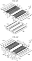
- a method of manufacturing the plug connector 21 as above is described. As shown in FIG. 21 , the plug contacts 61 constituting the contact array T1 and the plug contacts 61 constituting the contact array T2 are joined to a single carrier 63A via associated joint portions 62, and the plug contacts 61 constituting the contact array T4 and the plug contacts 61 constituting the contact array T3 are joined to another single carrier 63B via associated joint portions 62.
- the joint portions 62 connect the mounting portions 61A of the respective plug contacts 61 to the corresponding carrier 63A or 63B.
- the plug contacts 61 constituting the contact array T1 and the plug contacts 61 constituting the contact array T2 are arranged so as not to overlap each other in the X direction. This configuration allows the plug contacts 61 constituting the contact array T1 and the plug contacts 61 constituting the contact array T2 to be joined to the single carrier 63A.
- the plug contacts 61 constituting the contact array T4 and the plug contacts 61 constituting the contact array T3 are arranged so as not to overlap each other in the X direction. This configuration allows the plug contacts 61 constituting the contact array T4 and the plug contacts 61 constituting the contact array T3 to be joined to the other single carrier 63B.
- the plug contacts 61 of the contact arrays T1 to T4 are fitted and accommodated into the corresponding contact accommodating grooves 58 of the plug housing 51.
- the portion to be retained 61C having the pair of jutting portions 61D shown in FIG. 17 in each plug contact 61 is press-fitted into and retained by the retaining portion of the corresponding contact accommodating groove 58.
- all of the plug contacts 61 of the contact arrays T1 to T4 can be press-fitted together into the plug housing 51 by means of the two carriers 63A and 63B in one step.
- the joint portions 62 connecting the plug contacts 61 of the contact array T1 to the carrier 63A extend in the +X direction from the +X directional end of the plug housing 51, and the joint portions 62 connecting the plug contacts 61 of the contact array T2 to the carrier 63A extend across the opening portion 56A of the plug housing 51 that is situated on the +X direction side of the contact array T2 and further extend in the +X direction from the +X directional end of the plug housing 51.
- joint portions 62 connecting the plug contacts 61 of the contact array T4 to the carrier 63B extend in the -X direction from the -X directional end of the plug housing 51
- the joint portions 62 connecting the plug contacts 61 of the contact array T3 to the carrier 63B extend across the opening portion 56B of the plug housing 51 that is situated on the -X direction side of the contact array T3 and further extend in the -X direction from the -X directional end of the plug housing 51.
- each of the four carrier separating tools 64 is a plate member extending along a YZ plane and is provided at its +Z directional end with a blade portion extending along the Y direction.
- the four carrier separating tools 44 are arranged at intervals in the X direction.
- the carrier separating tool 64 situated furthest on the +X direction side is disposed slightly away from the +X directional end of the plug housing 51 in the +X direction
- the carrier separating tool 64 situated furthest on the -X direction side is disposed slightly away from the -X directional end of the plug housing 51 in the -X direction.
- the carrier separating tool 64 that is the second from the end on the +X direction side is disposed at a position corresponding to the opening portion 56A of the plug housing 51 that is situated on the +X direction side of the contact array T2
- the carrier separating tool 64 that is the second from the end on the -X direction side is disposed at a position corresponding to the opening portion 56B of the plug housing 51 that is situated on the -X direction side of the contact array T3.
- the four carrier separating tools 64 as above are moved from the -Z direction side toward the +Z direction side, and the blade portions at the +Z directional ends of the carrier separating tools 64 are each pressed to the joint portions 62 of the corresponding carrier 63A or 63B; as a result, the joint portions 62 are cut, and the plug contacts 61 are separated from the carrier 63A or 63B.
- the carrier separating tool 64 situated furthest on the +X direction side is moved in the +Z direction along a course slightly away from the +X directional end of the plug housing 51 in the +X direction, whereby the plug contacts 61 of the contact array T1 are separated from the carrier 63A, and the carrier separating tool 64 that is the second from the end on the +X direction side is moved in the +Z direction through the opening portion 56A of the plug housing 51, whereby the plug contacts 61 of the contact array T2 are separated from the carrier 63A.
- the mounting portions 61A of the plug contacts 61 of the contact array T1 all extend in the +X direction so as to protrude from the +X directional end of the plug housing 51, and the mounting portions 61A of the plug contacts 61 of the contact array T2 all extend in the +X direction so as to protrude in the opening portion 56A of the plug housing 51.
- the carrier separating tool 64 situated furthest on the -X direction side is moved in the +Z direction along a course slightly away from the -X directional end of the plug housing 51 in the -X direction, whereby the plug contacts 61 of the contact array T4 are separated from the carrier 63B, and the carrier separating tool 64 that is the second from the end on the -X direction side is moved in the +Z direction through the opening portion 56B of the plug housing 51 that is situated on the -X direction side of the contact array T3, whereby the plug contacts 61 of the contact array T3 are separated from the carrier 63B.
- the mounting portions 61A of the plug contacts 61 of the contact array T4 all extend in the -X direction so as to protrude from the -X directional end of the plug housing 51, and the mounting portions 61A of the plug contacts 61 of the contact array T3 all extend in the -X direction so as to protrude in the opening portion 56B of the plug housing 51.
- all of the plug contacts 61 of the contact arrays T1 to T4 can be separated together from the carriers 63A and 63B by means of the four carrier separating tools 64 in one step.
- the foregoing method makes it possible to manufacture the plug connector 21 having a large number of plug contacts 61 with fewer manufacturing steps.
- the connector assembly in the fitting state is shown in FIGS. 23 and 24 .
- the plug connector 21 With the plug connector 21 being aligned with the receptacle connector 11, the plug connector 21 is pressed to the receptacle connector 11 in the -Z direction so that the plug connector 21 is fitted into the receptacle connector 11, thus making the connector assembly.
- the peripheral wall portion 53 of the plug housing 51 of the plug connector 21 enters the area surrounded by the peripheral wall portion 33 of the receptacle housing 31 of the receptacle connector 11, and the three positioning projection portions 57 of the plug connector 21 are inserted into the three positioning recess portions 37 of the receptacle connector 11, correspondingly.
- the plug contacts 61 constituting the contact arrays T1 and T4 of the plug connector 21 come into contact with the receptacle contacts 41 constituting the contact arrays S1 and S4 of the receptacle connector 11, correspondingly.
- the contact portion 61B of each plug contact 61 shown in FIG. 17 comes into contact with the contact portion 41B of the corresponding receptacle contact 41 shown in FIG. 7 with predetermined contact pressure, whereby the plug contacts 61 and the receptacle contacts 41 are electrically connected to each other.
- the plug contacts 61 constituting the contact arrays T2 and T3 of the plug connector 21 come into contact with the receptacle contacts 41 constituting the contact arrays S2 and S3 of the receptacle connector 11, correspondingly, whereby the plug contacts 61 and the receptacle contacts 41 are electrically connected to each other.
- the plug connector 21 Since the three positioning projection portions 57 of the plug connector 21 are inserted into the three positioning recess portions 37 of the receptacle connector 11, correspondingly, the plug connector 21 can be prevented from being fitted with the receptacle connector 11 in a wrong orientation.
- the receptacle contacts 41 constituting the contact array S1 and the receptacle contacts 41 constituting the contact array S2 are arranged so as not to overlap each other at all in the X direction, it suffices if the former contacts 41 and the latter contacts 41 are in a position other than a position where the former contacts 41 and the latter contacts 41 completely coincide with each other in the X direction.
- the former contacts 41 and the latter contacts 41 can be joined to the single carrier 43A even when they partially overlap each other in the X direction.
- the mounting portions 41A of the receptacle contacts 41 constituting the contact array S1 and the mounting portions 41A of the receptacle contacts 41 constituting the contact array S2 are arranged to overlap each other in the X direction
- the contact portions 41B of the receptacle contacts 41 constituting the contact array S1 and the contact portions 41B of the receptacle contacts 41 constituting the contact array S2 are arranged so as not to overlap each other in the X direction
- the receptacle contacts 41 constituting the contact array S4 and the receptacle contacts 41 constituting the contact array S3 are arranged so as not to overlap each other at all in the X direction, it suffices if the former contacts 41 and the latter contacts 41 are in a position other than a position where the former contacts 41 and the latter contacts 41 completely coincide with each other in the X direction.
- the former contacts 41 and the latter contacts 41 can be joined to the single carrier 43B even when they partially overlap each other in the X direction.
- the plug contacts 61 constituting the contact array T1 and the plug contacts 61 constituting the contact array T2 do not completely coincide with each other in the X direction, and the former contacts 61 and the latter contacts 61 can be joined to the single carrier 63A even when they partially overlap each other.
- the plug contacts 61 constituting the contact array T4 and the plug contacts 61 constituting the contact array T3 do not completely coincide with each other in the X direction, and the former contacts 61 and the latter contacts 61 can be joined to the single carrier 63B even when they partially overlap each other.
- the receptacle connector 11 has the four contact arrays S1 to S4, and the plug connector 21 has the four contact arrays T1 to T4; however, the invention is not limited thereto, and it suffices if the receptacle connector 11 and the plug connector 21 each have two or more contact arrays.
- the receptacle contacts 41 constituting the two contact arrays S1 and S2 are all joined to the single carrier 43A, so that all of the receptacle contacts 41 can be press-fitted together into the receptacle housing 31 in one step and separated together from the carrier 43A in another one step.
- the plug contacts 61 constituting the two contact arrays T1 and T2 are all joined to the single carrier 63A, so that all of the plug contacts 61 can be press-fitted together into the plug housing 51 in one step and separated together from the carrier 63A in another one step.
- the number of contact arrays joined to one carrier is not limited to two, and three or more contact arrays may be joined to one carrier.
- each contact array is formed by aligning the plural receptacle contacts 41 or the plural plug contacts 61, and the number of the receptacle contacts 41 or the plug contacts 61 aligned in one contact array is not limited.
Landscapes
- Engineering & Computer Science (AREA)
- Manufacturing & Machinery (AREA)
- Coupling Device And Connection With Printed Circuit (AREA)
- Manufacturing Of Electrical Connectors (AREA)
Abstract
Description
- The present invention relates to a connector, particularly to a connector mounted on a mounting object and connected to a counter connector.
- The present invention also relates to a method of manufacturing such a connector.
- As a connector having a large number of contacts, for example,
JP 2017-84736 A receptacle connector 1 and aplug connector 2 both of which have a substantially flat plate shape, as shown inFIG. 27 . - The
receptacle connector 1 has a plurality ofreceptacle contacts 4 press-fitted in and retained by areceptacle housing 3 of flat plate shape, and theplug connector 2 has a plurality ofplug contacts 6 press-fitted in and retained by aplug housing 5 of flat plate shape. Thereceptacle contacts 4 form fourcontact arrays 7 linearly extending in parallel to each other, and theplug contacts 6 form fourcontact arrays 8 linearly extending in parallel to each other so as to correspond to the fourcontact arrays 7 of thereceptacle connector 1. - When the
plug connector 2 is fitted to thereceptacle connector 1, as shown inFIG. 28 , theplug contacts 6 forming the fourcontact arrays 8 are connected to thereceptacle contacts 4 forming the fourcontact arrays 7 correspondingly, thus making a connector assembly.FIG. 28 is a cross-sectional view cut along a plane orthogonal to the direction in which thecontact arrays - In manufacture of the
receptacle connector 1, since eachcontact array 7 hasplural receptacle contacts 4,receptacle contacts 4 constituting onecontact array 7 can be press-fitted together into thereceptacle housing 3 while being joined to a single carrier, and then, the carrier can be separated from thereceptacle contacts 4 at a time by means of a carrier cutting tool. Thus, a step involving collective press-fitting ofplural receptacle contacts 4 joined to a carrier and collective separation thereof is repeated four times to manufacture thereceptacle connector 1 having the fourcontact arrays 7. - Also for the
plug connector 2, on the basis of eachcontact array 8, collective press-fitting ofplural plug contacts 6 joined to a carrier and collective separation thereof are serially carried out, thus manufacturing theplug connector 2 having the fourcontact arrays 8 in the same manner as that for thereceptacle connector 1. - As shown in
FIG. 28 , however, in thereceptacle connector 1 ofJP 2017-84736 A receptacle contacts 4 constituting the fourcontact arrays 7 are disposed to coincide each other in the direction perpendicular to thecontact arrays 7; similarly, in theplug connector 2, theplug contacts 6 constituting the fourcontact arrays 8 are disposed to coincide each other in the direction perpendicular to thecontact arrays 8. - Therefore, in manufacture of the
receptacle connector 1, it is difficult to joinplural receptacle contacts 4 ofplural contact arrays 7, e.g., twocontact arrays 7 adjacent to each other to a single carrier, and accordingly, press-fitting and separation of theplural receptacle contacts 4 need to be carried out using separate carriers for therespective contact arrays 7. Similarly, also in manufacture of theplug connector 2, it is difficult to joinplural plug contacts 6 ofplural contact arrays 8 to a single carrier, and accordingly, press-fitting and separation of theplural plug contacts 6 need to be carried out using separate carriers for therespective contact arrays 8. - Thus, many steps are required to manufacture the
receptacle connector 1 and theplug connector 2, disadvantageously. - The present invention has been made to solve the conventional problem described above and is aimed at providing a connector that allows facilitation of its manufacturing process despite that the connector has a large number of contacts.
- The present invention is also aimed at providing a method of manufacturing such a connector.
- A connector according to the present invention is a connector mounted on a mounting object and connected to a counter connector, the connector comprising:
- a housing; and
- a plurality of contacts retained by the housing,
- wherein the plurality of contacts form a plurality of contact arrays that linearly extend in a predetermined array direction in parallel to each other,
- wherein each of the plurality of contacts has a mounting portion that is fixed to the mounting object when the connector is mounted on the mounting object and a contact portion that contacts a corresponding contact of the counter connector when the connector is connected to the counter connector,
- wherein the mounting portions of contacts constituting at least two contact arrays adjacent to each other of the plurality of contact arrays extend in a same elongation direction, and
- wherein contacts constituting each contact array of the at least two contact arrays are disposed in a position other than a position where those contacts completely coincide with contacts constituting another contact array of the at least two contact arrays in a direction perpendicular to the predetermined array direction.
- A method of manufacturing a connector according to the present invention comprises:
- a step of retaining a plurality of contacts joined to a carrier via corresponding joint portions by a housing; and
- a step of separating the carrier from the plurality of contacts retained by the housing,
- wherein the plurality of contacts form a plurality of contact arrays that linearly extend in a predetermined array direction in parallel to each other,
- wherein the joint portions joined to contacts constituting at least two contact arrays adjacent to each other of the plurality of contact arrays extend in a same elongation direction, and
- wherein contacts constituting each contact array of the at least two contact arrays are disposed in a position other than a position where those contacts completely coincide with contacts constituting another contact array of the at least two contact arrays in a direction perpendicular to the predetermined array direction.
-
-
FIG. 1 is a perspective view showing a connector assembly composed of a receptacle connector and a plug connector according to an embodiment of the invention, before fitting. -
FIG. 2 is a perspective view of the receptacle connector, when viewed from an obliquely upper position. -
FIG. 3 is a perspective view of the receptacle connector, when viewed from an obliquely lower position. -
FIG. 4 is a plan view showing the receptacle connector. -
FIG. 5 is an enlarged partial perspective view showing a receptacle housing used in the receptacle connector. -
FIG. 6 is a plan view showing a connector accommodating groove of the receptacle housing used in the receptacle connector. -
FIG. 7 is a perspective view showing a receptacle contact used in the receptacle connector. -
FIG. 8 is an enlarged partial plan view of the receptacle connector. -
FIG. 9 is a cross-sectional view taken along line A-A inFIG. 4 . -
FIG. 10 is a cross-sectional view taken along line B-B inFIG. 4 . -
FIG. 11 is a view showing a step of attaching receptacle contacts joined to carriers to the receptacle housing. -
FIG. 12 is a view showing a step of separating the carriers from the receptacle contacts attached to the receptacle housing. -
FIG. 13 is a perspective view of the plug connector, when viewed from an obliquely upper position. -
FIG. 14 is a perspective view of the plug connector, when viewed from an obliquely lower position. -
FIG. 15 is a plan view showing the plug connector. -
FIG. 16 is an enlarged partial perspective view showing a plug housing used in the plug connector. -
FIG. 17 is a perspective view showing a plug contact used in the plug connector. -
FIG. 18 is an enlarged partial plan view of the plug connector. -
FIG. 19 is a cross-sectional view taken along line C-C inFIG. 15 . -
FIG. 20 is a cross-sectional view taken along line D-D inFIG. 15 . -
FIG. 21 is a view showing a step of attaching plug contacts joined to carriers to the plug housing. -
FIG. 22 is a view showing a step of separating the carriers from the plug contacts attached to the plug housing. -
FIG. 23 is a perspective view showing the connector assembly in a fitted state. -
FIG. 24 is a plan view showing the connector assembly in a fitted state. -
FIG. 25 is a cross-sectional view taken along line E-E inFIG. 24 . -
FIG. 26 is a cross-sectional view taken along line F-F inFIG. 24 . -
FIG. 27 is a perspective view showing a conventional connector assembly before fitting. -
FIG. 28 is a cross-sectional view of the conventional connector assembly in a fitted state. - An embodiment of the present invention is described below with reference to the accompanying drawings.
-
FIG. 1 shows a receptacle connector (connector) 11 and a plug connector (connector) 21 according to the embodiment before theconnectors receptacle connector 11 and theplug connector 21 constitute a connector assembly, each have a substantially rectangular flat plate shape, and are arranged in parallel to each other. - The
receptacle connector 11 has a receptacle housing (housing) 31 and a plurality of receptacle contacts (contacts) 41 retained by thereceptacle housing 31. Thereceptacle contacts 41 form four contact arrays S1 to S4 linearly extending in a predetermined array direction in parallel to each other. Similarly, theplug connector 21 has a plug housing (housing) 51 and a plurality of plug contacts (contacts) 61 retained by theplug housing 51. Theplug contacts 61 form four contact arrays T1 to T4 linearly extending in the same array direction as that of the contact arrays S1 to S4 of thereceptacle connector 11 in parallel to each other. - The contact arrays S1 to S4 of the
receptacle connector 11 and the contact arrays T1 to T4 of theplug connector 21 extend in the same direction. - In the state where the
receptacle connector 11 and theplug connector 21 are fitted with each other, thereceptacle contacts 41 in the contact arrays S1 to S4 of thereceptacle connector 11 are correspondingly connected to theplug contacts 61 in the contact arrays T1 to T4 of theplug connector 21. - For convenience, the plane in which the
receptacle connector 11 of substantially flat plate shape extends is called "XY plane," the predetermined array direction in which the contact arrays S1 to S4 of thereceptacle connector 11 extend "Y direction," the direction in which the contact arrays S1 to S4 are arranged "X direction," and the direction perpendicular to an XY plane and from thereceptacle connector 11 toward theplug connector 21 "+Z direction." - As with the
receptacle connector 11, theplug connector 21 extends along an XY plane, the contact arrays T1 to T4 of theplug connector 21 extend in the Y direction, and the contact arrays T1 to T4 are arranged in the X direction. - The
receptacle connector 11 is able to fit with theplug connector 21 serving as a counter connector, and as shown inFIGS. 2 to 4 , has a center line C1 extending in the Y direction. In thereceptacle connector 11, the contact arrays S1 and S2 are disposed on the +X direction side of the center line C1, and the contact arrays S3 and S4 are disposed on the -X direction side of the center line C1. - The
receptacle housing 31 of thereceptacle connector 11 is made of an insulating body such as insulating resin, has a substantially flat plate shape, and includes aflat surface portion 32 extending along an XY plane on the -Z side of thereceptacle housing 31. Aperipheral wall portion 33 protruding in the +Z direction is formed along the outer periphery of theflat surface portion 32, and three projectingportions 34 are formed in the area surrounded by theperipheral wall portion 33 and project in the +Z direction from theflat surface portion 32 while extending in the Y direction in parallel to each other. The three projectingportions 34 have the same length in the Y direction, and one projectingportion 34 situated in the middle in the X direction is wider in the X direction than each of the projectingportions 34 situated in the opposite sides in the X direction. - The
receptacle housing 31 has four contactarray retaining portions 35 disposed separately on the +X direction side of, among the three projectingportions 34, the projectingportion 34 furthest on the +X direction side, on the +X direction side and the -X direction side of the projectingportion 34 situated in the middle in the X direction, and on the -X direction side of the projectingportion 34 furthest on the -X direction side. The four contactarray retaining portions 35 extend in the Y direction and separately retain the contact arrays S1 to S4. - In the
receptacle housing 31, anopening portion 36A extending in the Y direction and penetrating thereceptacle housing 31 in the Z direction is formed between the contactarray retaining portion 35 disposed on the +X direction side of the projectingportion 34 situated in the middle in the X direction and the projectingportion 34 furthest on the +X direction side. Similarly, anopening portion 36B extending in the Y direction and penetrating thereceptacle housing 31 in the Z direction is formed between the contactarray retaining portion 35 disposed on the -X direction side of the projectingportion 34 situated in the middle in the X direction and the projectingportion 34 furthest on the -X direction side. - Two
positioning recess portions 37 are formed in theperipheral wall portion 33 at the +Y directional end of thereceptacle housing 31 at a certain interval in the X direction to open in the +Z direction, while onepositioning recess portion 37 is formed in theperipheral wall portion 33 at the -Y directional end of thereceptacle housing 31 to open in the +Z direction. - As shown in
FIG. 5 , each contactarray retaining portion 35 has a plurality ofcontact accommodating grooves 38 aligned in the Y direction. Eachcontact accommodating groove 38 extends in the X direction and opens in the -Z direction. As shown inFIG. 6 , thecontact accommodating groove 38 is provided in its inside with a pair ofprojections 38A that project separately from the inner surfaces on the +Y and -Y direction sides of thecontact accommodating groove 38 such that the tips of theprojections 38A face each other. Thoseprojections 38A and an X directional end of thecontact accommodating groove 38 constitute a retainingportion 38B for retaining the correspondingreceptacle contact 41. - As shown in
FIG. 7 , thereceptacle contact 41 is formed by bending a band-shaped metal plate having electrical conductivity, and has a mountingportion 41A at its one end and acontact portion 41B at its other end. The mountingportion 41A extends along an XY plane and, when thereceptacle connector 11 is mounted onto a mounting object such as a circuit board, is joined and fixed to a connecting pad or the like of the mounting object. Meanwhile, thecontact portion 41B is a spring contact that is elastically displaceable in the X direction and when thereceptacle connector 11 is connected to theplug connector 21 serving as the counter connector, comes into contact with thecorresponding plug contact 61 of theplug connector 21. - The
receptacle contact 41 further has a portion to be retained 41C between the mountingportion 41A and thecontact portion 41B. The portion to be retained 41C has a pair of juttingportions 41D jutting separately in the +Y direction and the -Y direction from the band-shaped metal plate forming thereceptacle contact 41. By press-fitting the portion to be retained 41C having the juttingportions 41D into the retainingportion 38B of the correspondingcontact accommodating groove 38 of thereceptacle housing 31 from the -Z direction side, thereceptacle contact 41 is retained by thecontact accommodating groove 38. - The
receptacle contact 41 has a larger width in the Y direction at the pair of juttingportions 41D than that at the other portions, and the width in the Y direction of thereceptacle contact 41 at the pair of juttingportions 41D is defined as a contact width W1. - As shown in
FIG. 8 , thereceptacle contacts 41 constituting each of the contact arrays S1 to S4 are aligned in the Y direction at a predetermined array pitch P1, and the adjacent contact arrays S1 and S2 are arranged to be offset from each other in the Y direction by an offset amount P2 equal to a half of the array pitch P1. The array pitch P1 is set to be larger than a double of the contact width W1 of thereceptacle contact 41. In other words, the offset amount P2 equal to a half of the array pitch P1 is set to be larger than the contact width W1 of thereceptacle contact 41. - Accordingly, the
receptacle contacts 41 constituting the contact array S1 and thereceptacle contacts 41 constituting the contact array S2 are arranged to be offset from each other in the Y direction by the offset amount P2 and do not overlap each other at all in the X direction perpendicular to the Y direction. - As can be seen from
FIG. 4 , the adjacent contact arrays S3 and S4 are also arranged to be offset from each other in the Y direction by the offset amount P2. Thereceptacle contacts 41 constituting the contact array S3 and thereceptacle contacts 41 constituting the contact array S4 are arranged to be offset from each other in the Y direction by the offset amount P2 and do not overlap each other at all in the X direction perpendicular to the Y direction. - The contact arrays S1 and S4 are disposed at the same position in the Y direction with no offset, and the contact arrays S2 and S3 are also disposed at the same position in the Y direction with no offset.
- Therefore, when the
receptacle connector 11 is cut along an XZ plane passing through givenreceptacle contacts 41 of the contact arrays S1 and S4, as shown inFIG. 9 , thereceptacle contact 41 of the contact array S1 and thereceptacle contact 41 of the contact array S4 appear in the cross section, whereas for the contact arrays S2 and S3, noreceptacle contact 41 appears in the cross section with only a section of thereceptacle housing 31 being seen. - Similarly, when the
receptacle connector 11 is cut along an XZ plane passing through givenreceptacle contacts 41 of the contact arrays S2 and S3, as shown inFIG. 10 , thereceptacle contact 41 of the contact array S2 and thereceptacle contact 41 of the contact array S3 appear in the cross section, whereas for the contact arrays S1 and S4, noreceptacle contact 41 appears in the cross section with only a section of thereceptacle housing 31 being seen. - On the +X direction side in the
receptacle connector 11, all of the mountingportions 41A of thereceptacle contacts 41 of the adjacent contact arrays S1 and S2 extend in the +X direction, which is an elongation direction, along theflat surface portion 32 of thereceptacle housing 31. All of the mountingportions 41A of thereceptacle contacts 41 of the contact array S1 protrude in the +X direction from the +X directional end of thereceptacle housing 31, and all of the mountingportions 41A of thereceptacle contacts 41 of the contact array S2 protrude in theopening portion 36A of thereceptacle housing 31 that is situated on the +X direction side of the contact array S2. - Similarly, on the -X direction side in the
receptacle connector 11, all of the mountingportions 41A of thereceptacle contacts 41 of the adjacent contact arrays S3 and S4 extend in the -X direction, which is an elongation direction, along an XY plane. All of the mountingportions 41A of thereceptacle contacts 41 of the contact array S3 protrude in theopening portion 36B of thereceptacle housing 31 that is situated on the - X direction side of the contact array S3, and all of the mountingportions 41A of thereceptacle contacts 41 of the contact array S4 protrude in the -X direction from the -X directional end of thereceptacle housing 31. - A method of manufacturing the
receptacle connector 11 as above is described. As shown inFIG. 11 , thereceptacle contacts 41 constituting the contact array S1 and thereceptacle contacts 41 constituting the contact array S2 are joined to asingle carrier 43A via associatedjoint portions 42, and thereceptacle contacts 41 constituting the contact array S4 and thereceptacle contacts 41 constituting the contact array S3 are joined to anothersingle carrier 43B via associatedjoint portions 42. Thejoint portions 42 connect the mountingportions 41A of therespective receptacle contacts 41 to thecorresponding carrier - Note that, as shown in
FIG. 8 , thereceptacle contacts 41 constituting the contact array S1 and thereceptacle contacts 41 constituting the contact array S2 are arranged so as not to overlap each other in the X direction. This configuration allows thereceptacle contacts 41 constituting the contact array S1 and thereceptacle contacts 41 constituting the contact array S2 to be joined to thesingle carrier 43A. - Similarly, the
receptacle contacts 41 constituting the contact array S4 and thereceptacle contacts 41 constituting the contact array S3 are arranged so as not to overlap each other in the X direction. This configuration allows thereceptacle contacts 41 constituting the contact array S4 and thereceptacle contacts 41 constituting the contact array S3 to be joined to the othersingle carrier 43B. - When the two
carriers receptacle housing 31 from the -Z direction side to the +Z direction side, thereceptacle contacts 41 of the contact arrays S1 to S4 are fitted and accommodated into the correspondingcontact accommodating grooves 38 of thereceptacle housing 31. At this time, the portion to be retained 41C having the pair of juttingportions 41D shown inFIG. 7 in eachreceptacle contact 41 is press-fitted into and retained by the retainingportion 38B of the correspondingcontact accommodating groove 38 shown inFIG. 6 . - Thus, as shown in
FIG. 12 , all of thereceptacle contacts 41 of the contact arrays S1 to S4 can be press-fitted together into thereceptacle housing 31 by means of the twocarriers - The
joint portions 42 connecting thereceptacle contacts 41 of the contact array S1 to thecarrier 43A extend in the +X direction from the +X directional end of thereceptacle housing 31, and thejoint portions 42 connecting thereceptacle contacts 41 of the contact array S2 to thecarrier 43A extend across theopening portion 36A of thereceptacle housing 31 that is situated on the +X direction side of the contact array S2 and further extend in the +X direction from the +X directional end of thereceptacle housing 31. - In contrast, the
joint portions 42 connecting thereceptacle contacts 41 of the contact array S4 to thecarrier 43B extend from the -X directional end of thereceptacle housing 31 toward the -X direction, and thejoint portions 42 connecting thereceptacle contacts 41 of the contact array S3 to thecarrier 43B extend across theopening portion 36B of thereceptacle housing 31 that is situated on the -X direction side of the contact array S3 and further extend from the -X directional end of thereceptacle housing 31 toward the -X direction. - Next, as shown in
FIG. 12 , thereceptacle contacts 41 are separated from the twocarriers carrier separating tools 44. Each of the fourcarrier separating tools 44 is a plate member extending along a YZ plane and is provided at its -Z directional end with a blade portion extending along the Y direction. The fourcarrier separating tools 44 are arranged at intervals in the X direction. - Of the four
carrier separating tools 44, thecarrier separating tool 44 situated furthest on the +X direction side is disposed slightly away from the +X directional end of thereceptacle housing 31 in the +X direction, and thecarrier separating tool 44 situated furthest on the -X direction side is disposed slightly away from the -X directional end of thereceptacle housing 31 in the -X direction. - Further, of the four
carrier separating tools 44, thecarrier separating tool 44 that is the second from the end on the +X direction side is disposed at a position corresponding to theopening portion 36A of thereceptacle housing 31 that is situated on the +X direction side of the contact array S2, and thecarrier separating tool 44 that is the second from the end on the -X direction side is disposed at a position corresponding to theopening portion 36B of thereceptacle housing 31 that is situated on the -X direction side of the contact array S3. - The four
carrier separating tools 44 as above are moved from the +Z direction side toward the -Z direction side, and the blade portions at the -Z directional ends of thecarrier separating tools 44 are each pressed to thejoint portions 42 of thecorresponding carrier joint portions 42 are cut, and thereceptacle contacts 41 are separated from thecarrier - In this process, of the four
carrier separating tools 44, thecarrier separating tool 44 situated furthest on the +X direction side is moved in the -Z direction along a course slightly away from the +X directional end of thereceptacle housing 31 in the +X direction, whereby thereceptacle contacts 41 of the contact array S1 are separated from thecarrier 43A, and thecarrier separating tool 44 that is the second from the end on the +X direction side is moved in the -Z direction through theopening portion 36A of thereceptacle housing 31, whereby thereceptacle contacts 41 of the contact array S2 are separated from thecarrier 43A. - Since the
receptacle contacts 41 of the contact array S1 and thereceptacle contacts 41 of the contact array S2 are joined to thecarrier 43A situated on the +X direction side of thereceptacle housing 31 via the correspondingjoint portions 42, once thejoint portions 42 are cut, consequently, the mountingportions 41A of thereceptacle contacts 41 of the contact array S1 all extend in the +X direction so as to protrude from the +X directional end of thereceptacle housing 31, and the mountingportions 41A of thereceptacle contacts 41 of the contact array S2 all extend in the +X direction so as to protrude in theopening portion 36A of thereceptacle housing 31. - Further, of the four
carrier separating tools 44, thecarrier separating tool 44 situated furthest on the -X direction side is moved in the -Z direction along a course slightly away from the -X directional end of thereceptacle housing 31 in the -X direction, whereby thereceptacle contacts 41 of the contact array S4 are separated from thecarrier 43B, and thecarrier separating tool 44 that is the second from the end on the -X direction side is moved in the -Z direction through theopening portion 36B of thereceptacle housing 31 that is situated on the -X direction side of the contact array S3, whereby thereceptacle contacts 41 of the contact array S3 are separated from thecarrier 43B. - Since the
receptacle contacts 41 of the contact array S4 and thereceptacle contacts 41 of the contact array S3 are joined to thecarrier 43B situated on the -X direction side of thereceptacle housing 31 via the correspondingjoint portions 42, once thejoint portions 42 are cut, consequently, the mountingportions 41A of thereceptacle contacts 41 of the contact array S4 all extend in the -X direction so as to protrude from the -X directional end of thereceptacle housing 31, and the mountingportions 41A of thereceptacle contacts 41 of the contact array S3 all extend in the -X direction so as to protrude in theopening portion 36B of thereceptacle housing 31. - Thus, all of the
receptacle contacts 41 of the contact arrays S1 to S4 can be separated together from thecarriers carrier separating tools 44 in one step. - The foregoing method makes it possible to manufacture the
receptacle connector 11 having a large number ofreceptacle contacts 41 with fewer manufacturing steps. - The
plug connector 21 is able to fit with thereceptacle connector 11 serving as a counter connector, and as shown inFIGS. 13 to 15 , has a center line C2 extending in the Y direction. In theplug connector 21, the contact arrays T1 and T2 are disposed on the +X direction side of the center line C2, and the contact arrays T3 and T4 are disposed on the -X direction side of the center line C2. - The
plug housing 51 of theplug connector 21 is made of an insulating body such as insulating resin, has a substantially flat plate shape, and includes aflat surface portion 52 extending along an XY plane on the +Z side of theplug housing 51. Aperipheral wall portion 53 protruding in the -Z direction is formed along the outer periphery of theflat surface portion 52, and twopartition portions peripheral wall portion 53 and project in the -Z direction from theflat surface portion 52 while extending in the Y direction in parallel to each other. - The
plug housing 51 has four contactarray retaining portions 55 disposed separately on the -X direction side of the +X directional part of theperipheral wall portion 53, on the -X direction side of thepartition portion 54A situated on the +X direction side, on the +X direction side of thepartition portion 54B situated on the -X direction side, and on the +X direction side of the -X directional part of theperipheral wall portion 53. The four contactarray retaining portions 55 extend in the Y direction and separately retain the contact arrays T1 to T4. - In the
plug housing 51, anopening portion 56A extending in the Y direction and penetrating theplug housing 51 in the Z direction is formed on the +X direction side of thepartition portion 54A situated on the +X direction side, and anopening portion 56B extending in the Y direction and penetrating theplug housing 51 in the Z direction is formed on the -X direction side of thepartition portion 54B situated on the -X direction side. - Two
positioning projection portions 57 are formed on theperipheral wall portion 53 at the +Y directional end of theplug housing 51 at a certain interval in the X direction to project in the +Y direction, while onepositioning projection portion 57 is formed on theperipheral wall portion 53 at the -Y directional end of theplug housing 51 to project in the +Y direction. - As shown in
FIG. 16 , each contactarray retaining portion 55 has a plurality ofcontact accommodating grooves 58 aligned in the Y direction. Although not illustrated, eachcontact accommodating groove 58 is provided in its inside with a retaining portion for retaining thecorresponding plug contact 61. - As shown in
FIG. 17 , theplug contact 61 is formed by bending a band-shaped metal plate having electrical conductivity, and has a mountingportion 61A at its one end and acontact portion 61B at its other end. The mountingportion 61A extends along an XY plane and, when theplug connector 21 is mounted onto a mounting object such as a circuit board, is joined and fixed to a connecting pad or the like of the mounting object. Meanwhile, thecontact portion 61B is a fixed contact that is not elastically displaceable and, when theplug connector 21 is connected to thereceptacle connector 11 serving as the counter connector, comes into contact with the correspondingreceptacle contact 41 of thereceptacle connector 11. - The
plug contact 61 further has a portion to be retained 61C between the mountingportion 61A and thecontact portion 61B. The portion to be retained 61C has a pair of juttingportions 61D jutting separately in the +Y direction and the -Y direction from the band-shaped metal plate forming theplug contact 61. By press-fitting the portion to be retained 61C having the juttingportions 61D into the retaining portion of the correspondingcontact accommodating groove 58 of theplug housing 51 from the +Z direction side, theplug contact 61 is retained by thecontact accommodating groove 58. - The
plug contact 61 has a larger width in the Y direction at the pair of juttingportions 61D than that at the other portions, and the width in the Y direction of theplug contact 61 at the pair of juttingportions 61D is defined as a contact width W2. - As shown in
FIG. 18 , theplug contacts 61 constituting each of the contact arrays T1 to T4 are aligned in the Y direction at the same array pitch P1 as that of thereceptacle contacts 41 of thereceptacle connector 11, and the adjacent contact arrays T1 and T2 are arranged to be offset from each other in the Y direction by the offset amount P2 equal to a half of the array pitch P1. The array pitch P1 is set to be larger than a double of the contact width W2 of theplug contact 61. In other words, the offset amount P2 equal to a half of the array pitch P1 is set to be larger than the contact width W2 of theplug contact 61. - Accordingly, the
plug contacts 61 constituting the contact array T1 and theplug contacts 61 constituting the contact array T2 are arranged to be offset from each other in the Y direction by the offset amount P2 and do not overlap each other at all in the X direction perpendicular to the Y direction. - The adjacent contact arrays T3 and T4 are also arranged to be offset from each other in the Y direction by the offset amount P2. The
plug contacts 61 constituting the contact array T3 and theplug contacts 61 constituting the contact array T4 are arranged to be offset from each other in the Y direction by the offset amount P2 and do not overlap each other at all in the X direction perpendicular to the Y direction. - The contact arrays T1 and T4 are disposed at the same position in the Y direction with no offset, and the contact arrays T2 and T3 are also disposed at the same position in the Y direction with no offset.
- Therefore, when the
plug connector 21 is cut along an XZ plane passing through givenplug contacts 61 of the contact arrays T1 and T4, as shown inFIG. 19 , theplug contact 61 of the contact array T1 and theplug contact 61 of the contact array T4 appear in the cross section, whereas for the contact arrays T2 and T3, noplug contact 61 appears in the cross section with only a section of theplug housing 51 being seen. - Similarly, when the
plug connector 21 is cut along an XZ plane passing through givenplug contacts 61 of the contact arrays T2 and T3, as shown inFIG. 20 , theplug contact 61 of the contact array T2 and theplug contact 61 of the contact array T3 appear in the cross section, whereas for the contact arrays T1 and T4, noplug contact 61 appears in the cross section with only a section of theplug housing 51 being seen. - On the +X direction side in the
plug connector 21, all of the mountingportions 61A of theplug contacts 61 of the adjacent contact arrays T1 and T2 extend in the +X direction, which is an elongation direction, along theflat surface portion 52 of theplug housing 51. All of the mountingportions 61A of theplug contacts 61 of the contact array T1 protrude in the +X direction from the +X directional end of theplug housing 51, and all of the mountingportions 61A of theplug contacts 61 of the contact array T2 protrude in theopening portion 56A of theplug housing 51 that is situated on the +X direction side of the contact array T2. - Similarly, on the -X direction side in the
plug connector 21, all of the mountingportions 61A of theplug contacts 61 of the adjacent contact arrays T3 and T4 extend in the -X direction, which is an elongation direction, along an XY plane. All of the mountingportions 61A of theplug contacts 61 of the contact array T3 protrude in theopening portion 56B of theplug housing 51 that is situated on the -X direction side of the contact array T3, and all of the mountingportions 61A of theplug contacts 61 of the contact array T4 protrude in the -X direction from the -X directional end of theplug housing 51. - A method of manufacturing the
plug connector 21 as above is described. As shown inFIG. 21 , theplug contacts 61 constituting the contact array T1 and theplug contacts 61 constituting the contact array T2 are joined to asingle carrier 63A via associatedjoint portions 62, and theplug contacts 61 constituting the contact array T4 and theplug contacts 61 constituting the contact array T3 are joined to anothersingle carrier 63B via associatedjoint portions 62. Thejoint portions 62 connect the mountingportions 61A of therespective plug contacts 61 to thecorresponding carrier - Note that, as shown in
FIG. 18 , theplug contacts 61 constituting the contact array T1 and theplug contacts 61 constituting the contact array T2 are arranged so as not to overlap each other in the X direction. This configuration allows theplug contacts 61 constituting the contact array T1 and theplug contacts 61 constituting the contact array T2 to be joined to thesingle carrier 63A. - Similarly, the
plug contacts 61 constituting the contact array T4 and theplug contacts 61 constituting the contact array T3 are arranged so as not to overlap each other in the X direction. This configuration allows theplug contacts 61 constituting the contact array T4 and theplug contacts 61 constituting the contact array T3 to be joined to the othersingle carrier 63B. - When the two
carriers plug housing 51 from the +Z direction side to the -Z direction side, theplug contacts 61 of the contact arrays T1 to T4 are fitted and accommodated into the correspondingcontact accommodating grooves 58 of theplug housing 51. At this time, the portion to be retained 61C having the pair of juttingportions 61D shown inFIG. 17 in eachplug contact 61 is press-fitted into and retained by the retaining portion of the correspondingcontact accommodating groove 58. - Thus, as shown in
FIG. 22 , all of theplug contacts 61 of the contact arrays T1 to T4 can be press-fitted together into theplug housing 51 by means of the twocarriers - The
joint portions 62 connecting theplug contacts 61 of the contact array T1 to thecarrier 63A extend in the +X direction from the +X directional end of theplug housing 51, and thejoint portions 62 connecting theplug contacts 61 of the contact array T2 to thecarrier 63A extend across theopening portion 56A of theplug housing 51 that is situated on the +X direction side of the contact array T2 and further extend in the +X direction from the +X directional end of theplug housing 51. - In contrast, the
joint portions 62 connecting theplug contacts 61 of the contact array T4 to thecarrier 63B extend in the -X direction from the -X directional end of theplug housing 51, and thejoint portions 62 connecting theplug contacts 61 of the contact array T3 to thecarrier 63B extend across theopening portion 56B of theplug housing 51 that is situated on the -X direction side of the contact array T3 and further extend in the -X direction from the -X directional end of theplug housing 51. - Next, as shown in
FIG. 22 , theplug contacts 61 are separated from the twocarriers carrier separating tools 64. Each of the fourcarrier separating tools 64 is a plate member extending along a YZ plane and is provided at its +Z directional end with a blade portion extending along the Y direction. The fourcarrier separating tools 44 are arranged at intervals in the X direction. - Of the four
carrier separating tools 64, thecarrier separating tool 64 situated furthest on the +X direction side is disposed slightly away from the +X directional end of theplug housing 51 in the +X direction, and thecarrier separating tool 64 situated furthest on the -X direction side is disposed slightly away from the -X directional end of theplug housing 51 in the -X direction. - Further, of the four
carrier separating tools 64, thecarrier separating tool 64 that is the second from the end on the +X direction side is disposed at a position corresponding to theopening portion 56A of theplug housing 51 that is situated on the +X direction side of the contact array T2, and thecarrier separating tool 64 that is the second from the end on the -X direction side is disposed at a position corresponding to theopening portion 56B of theplug housing 51 that is situated on the -X direction side of the contact array T3. - The four
carrier separating tools 64 as above are moved from the -Z direction side toward the +Z direction side, and the blade portions at the +Z directional ends of thecarrier separating tools 64 are each pressed to thejoint portions 62 of thecorresponding carrier joint portions 62 are cut, and theplug contacts 61 are separated from thecarrier - In this process, of the four
carrier separating tools 64, thecarrier separating tool 64 situated furthest on the +X direction side is moved in the +Z direction along a course slightly away from the +X directional end of theplug housing 51 in the +X direction, whereby theplug contacts 61 of the contact array T1 are separated from thecarrier 63A, and thecarrier separating tool 64 that is the second from the end on the +X direction side is moved in the +Z direction through theopening portion 56A of theplug housing 51, whereby theplug contacts 61 of the contact array T2 are separated from thecarrier 63A. - Since the
plug contacts 61 of the contact array T1 and theplug contacts 61 of the contact array T2 are joined to thecarrier 63A situated on the +X direction side of theplug housing 51 via the correspondingjoint portions 62, once thejoint portions 62 are cut, consequently, the mountingportions 61A of theplug contacts 61 of the contact array T1 all extend in the +X direction so as to protrude from the +X directional end of theplug housing 51, and the mountingportions 61A of theplug contacts 61 of the contact array T2 all extend in the +X direction so as to protrude in theopening portion 56A of theplug housing 51. - Further, of the four
carrier separating tools 64, thecarrier separating tool 64 situated furthest on the -X direction side is moved in the +Z direction along a course slightly away from the -X directional end of theplug housing 51 in the -X direction, whereby theplug contacts 61 of the contact array T4 are separated from thecarrier 63B, and thecarrier separating tool 64 that is the second from the end on the -X direction side is moved in the +Z direction through theopening portion 56B of theplug housing 51 that is situated on the -X direction side of the contact array T3, whereby theplug contacts 61 of the contact array T3 are separated from thecarrier 63B. - Since the
plug contacts 61 of the contact array T4 and theplug contacts 61 of the contact array T3 are joined to thecarrier 63B situated on the -X direction side of theplug housing 51 via the correspondingjoint portions 62, once thejoint portions 62 are cut, consequently, the mountingportions 61A of theplug contacts 61 of the contact array T4 all extend in the -X direction so as to protrude from the -X directional end of theplug housing 51, and the mountingportions 61A of theplug contacts 61 of the contact array T3 all extend in the -X direction so as to protrude in theopening portion 56B of theplug housing 51. - Thus, all of the
plug contacts 61 of the contact arrays T1 to T4 can be separated together from thecarriers carrier separating tools 64 in one step. - The foregoing method makes it possible to manufacture the
plug connector 21 having a large number ofplug contacts 61 with fewer manufacturing steps. - The connector assembly in the fitting state is shown in
FIGS. 23 and 24 . With theplug connector 21 being aligned with thereceptacle connector 11, theplug connector 21 is pressed to thereceptacle connector 11 in the -Z direction so that theplug connector 21 is fitted into thereceptacle connector 11, thus making the connector assembly. - In the fitting state, the
peripheral wall portion 53 of theplug housing 51 of theplug connector 21 enters the area surrounded by theperipheral wall portion 33 of thereceptacle housing 31 of thereceptacle connector 11, and the threepositioning projection portions 57 of theplug connector 21 are inserted into the threepositioning recess portions 37 of thereceptacle connector 11, correspondingly. - Consequently, as shown in
FIG. 25 , theplug contacts 61 constituting the contact arrays T1 and T4 of theplug connector 21 come into contact with thereceptacle contacts 41 constituting the contact arrays S1 and S4 of thereceptacle connector 11, correspondingly. Specifically, thecontact portion 61B of eachplug contact 61 shown inFIG. 17 comes into contact with thecontact portion 41B of thecorresponding receptacle contact 41 shown inFIG. 7 with predetermined contact pressure, whereby theplug contacts 61 and thereceptacle contacts 41 are electrically connected to each other. - Similarly, as shown in
FIG. 26 , theplug contacts 61 constituting the contact arrays T2 and T3 of theplug connector 21 come into contact with thereceptacle contacts 41 constituting the contact arrays S2 and S3 of thereceptacle connector 11, correspondingly, whereby theplug contacts 61 and thereceptacle contacts 41 are electrically connected to each other. - Since the three
positioning projection portions 57 of theplug connector 21 are inserted into the threepositioning recess portions 37 of thereceptacle connector 11, correspondingly, theplug connector 21 can be prevented from being fitted with thereceptacle connector 11 in a wrong orientation. - In the
receptacle connector 11, while thereceptacle contacts 41 constituting the contact array S1 and thereceptacle contacts 41 constituting the contact array S2 are arranged so as not to overlap each other at all in the X direction, it suffices if theformer contacts 41 and thelatter contacts 41 are in a position other than a position where theformer contacts 41 and thelatter contacts 41 completely coincide with each other in the X direction. Theformer contacts 41 and thelatter contacts 41 can be joined to thesingle carrier 43A even when they partially overlap each other in the X direction. - For instance, when the mounting
portions 41A of thereceptacle contacts 41 constituting the contact array S1 and the mountingportions 41A of thereceptacle contacts 41 constituting the contact array S2 are arranged to overlap each other in the X direction, and thecontact portions 41B of thereceptacle contacts 41 constituting the contact array S1 and thecontact portions 41B of thereceptacle contacts 41 constituting the contact array S2 are arranged so as not to overlap each other in the X direction, it is possible to connect thereceptacle contacts 41 constituting the contact array S1 and thereceptacle contacts 41 constituting the contact array S2 to thesingle carrier 43A. - Similarly, in the
receptacle connector 11, while thereceptacle contacts 41 constituting the contact array S4 and thereceptacle contacts 41 constituting the contact array S3 are arranged so as not to overlap each other at all in the X direction, it suffices if theformer contacts 41 and thelatter contacts 41 are in a position other than a position where theformer contacts 41 and thelatter contacts 41 completely coincide with each other in the X direction. Theformer contacts 41 and thelatter contacts 41 can be joined to thesingle carrier 43B even when they partially overlap each other in the X direction. - In the
plug connector 21, it suffices if theplug contacts 61 constituting the contact array T1 and theplug contacts 61 constituting the contact array T2 do not completely coincide with each other in the X direction, and theformer contacts 61 and thelatter contacts 61 can be joined to thesingle carrier 63A even when they partially overlap each other. - Similarly, it suffices if the
plug contacts 61 constituting the contact array T4 and theplug contacts 61 constituting the contact array T3 do not completely coincide with each other in the X direction, and theformer contacts 61 and thelatter contacts 61 can be joined to thesingle carrier 63B even when they partially overlap each other. - The
receptacle connector 11 has the four contact arrays S1 to S4, and theplug connector 21 has the four contact arrays T1 to T4; however, the invention is not limited thereto, and it suffices if thereceptacle connector 11 and theplug connector 21 each have two or more contact arrays. - For instance, when the
receptacle connector 11 has only two contact arrays S1 and S2, thereceptacle contacts 41 constituting the two contact arrays S1 and S2 are all joined to thesingle carrier 43A, so that all of thereceptacle contacts 41 can be press-fitted together into thereceptacle housing 31 in one step and separated together from thecarrier 43A in another one step. - Similarly, when the
plug connector 21 has only two contact arrays T1 and T2, theplug contacts 61 constituting the two contact arrays T1 and T2 are all joined to thesingle carrier 63A, so that all of theplug contacts 61 can be press-fitted together into theplug housing 51 in one step and separated together from thecarrier 63A in another one step. - The number of contact arrays joined to one carrier is not limited to two, and three or more contact arrays may be joined to one carrier.
- It suffices if each contact array is formed by aligning the
plural receptacle contacts 41 or theplural plug contacts 61, and the number of thereceptacle contacts 41 or theplug contacts 61 aligned in one contact array is not limited.
Claims (13)
- A connector (11, 21) mounted on a mounting object and connected to a counter connector (21, 11), the connector comprising:a housing (31, 51); anda plurality of contacts (41, 61) retained by the housing,wherein the plurality of contacts form a plurality of contact arrays (S1-S4, T1-T4) that linearly extend in a predetermined array direction (Y) in parallel to each other,wherein each of the plurality of contacts has a mounting portion (41A, 61A) that is fixed to the mounting object when the connector is mounted on the mounting object and a contact portion (41B, 61B) that contacts a corresponding contact of the counter connector when the connector is connected to the counter connector,wherein the mounting portions of contacts constituting at least two contact arrays adjacent to each other of the plurality of contact arrays extend in a same elongation direction, andwherein contacts constituting each contact array of the at least two contact arrays are disposed in a position other than a position where those contacts completely coincide with contacts constituting another contact array of the at least two contact arrays in a direction (X) perpendicular to the predetermined array direction.
- The connector according to claim 1,
wherein the housing (31, 51) has an opening portion (36A, 36B, 56A, 56B) formed between the at least two contact arrays and extending in the predetermined array direction. - The connector according to claim 2,
wherein the mounting portions of contacts constituting one contact array of two contact arrays situated on opposite sides across the opening portion protrude in the opening portion. - The connector according to any one of claims 1 to 3,
wherein the housing (31, 51) has a flat surface portion (32, 52) facing the mounting object, and
wherein the elongation direction of the mounting portions of the plurality of contacts is a direction (X) along the flat surface portion of the housing and perpendicular to the predetermined array direction (Y). - The connector according to any one of claims 1 to 4,
wherein the plurality of contacts (41, 61) are aligned in the predetermined array direction (Y) at a predetermined array pitch (PI) in each of the plurality of contact arrays,
wherein each of the plurality of contacts has a predetermined contact width (W1, W2) in the predetermined array direction,
wherein the at least two contact arrays comprise two adjacent contact arrays,
wherein the two adjacent contact arrays are arranged to be offset from each other by a half of the predetermined array pitch in the predetermined array direction, and
wherein the predetermined array pitch is larger than a double of the predetermined contact width. - The connector according to any one of claims 1 to 5,
wherein the connector has a center line (C1, C2) extending in the predetermined array direction, and
wherein the at least two contact arrays are disposed on each of opposite sides across the center line. - The connector according to claim 6,
wherein the mounting portions (41A, 61A) of contacts constituting the at least two contact arrays disposed on one of the opposite sides across the center line (C1, C2) and the mounting portions (41A, 61A) of contacts constituting the at least two contact arrays disposed on the other of the opposite sides across the center line (C1, C2) extend in opposite directions from each other. - The connector according to any one of claims 1 to 7,
wherein the mounting portions (41A, 61A) of contacts constituting each contact array of the at least two contact arrays are disposed in a position where those mounting portions overlap the mounting portions (41A, 61A) of contacts constituting another contact array of the at least two contact arrays in the direction (X) perpendicular to the predetermined array direction, and
wherein the contact portions (41B, 61B) of contacts constituting each contact array of the at least two contact arrays are disposed in a position where those contact portions do not overlap the contact portions (41B, 61B) of contacts constituting another contact array of the at least two contact arrays in the direction (X) perpendicular to the predetermined array direction. - The connector according to any one of claims 1 to 7,
wherein the contact portions (41B, 61B) of contacts constituting each contact array of the at least two contact arrays are disposed in a position where those contact portions overlap the contact portions (41B, 61B) of contacts constituting another contact array of the at least two contact arrays in the direction (X) perpendicular to the predetermined array direction, and
wherein the mounting portions (41A, 61A) of contacts constituting each contact array of the at least two contact arrays are disposed in a position where those mounting portions do not overlap the mounting portions (41A, 61A) of contacts constituting another contact array of the at least two contact arrays in the direction (X) perpendicular to the predetermined array direction. - The connector according to any one of claims 1 to 9,
wherein each of the plurality of contacts (41, 61) has a portion to be retained (41C, 61C) between the mounting portion and the contact portion,
wherein the housing (31, 51) has a plurality of retaining portions (38B) corresponding to the portions to be retained of the plurality of contacts, and
wherein the portions to be retained of the plurality of contacts are press-fitted in and retained by the plurality of retaining portions of the housing, correspondingly. - The connector according to any one of claims 1 to 10,
wherein the connector is a receptacle connector (11),
wherein the housing is a receptacle housing (31),
wherein the plurality of contacts are a plurality of receptacle contacts (41),
wherein each of the plurality of receptacle contacts has a spring contact (41B) that is elastically displaceable as the contact portion, and
wherein the counter connector is a plug connector (21) that is to be fitted with the receptacle connector to thereby form a connector assembly together with the receptacle connector. - The connector according to any one of claims 1 to 10,
wherein the connector is a plug connector (21),
wherein the housing is a plug housing (51),
wherein the plurality of contacts are a plurality of plug contacts (61),
wherein each of the plurality of plug contacts has a fixed contact (61B) that is secured in position as the contact portion, and
wherein the counter connector is a receptacle connector (11) that is to be fitted with the plug connector to thereby form a connector assembly together with the plug connector. - A method of manufacturing a connector, comprising:a step of retaining a plurality of contacts (41, 61) joined to a carrier (43A, 43B, 63A, 63B) via corresponding joint portions (42, 62) by a housing (31, 51); anda step of separating the carrier from the plurality of contacts retained by the housing,wherein the plurality of contacts form a plurality of contact arrays (S1-S4, T1-T4) that linearly extend in a predetermined array direction (Y) in parallel to each other,wherein the joint portions joined to contacts constituting at least two contact arrays adjacent to each other of the plurality of contact arrays extend in a same elongation direction, andwherein contacts constituting each contact array of the at least two contact arrays are disposed in a position other than a position where those contacts completely coincide with contacts constituting another contact array of the at least two contact arrays in a direction (X) perpendicular to the predetermined array direction.
Applications Claiming Priority (1)
| Application Number | Priority Date | Filing Date | Title |
|---|---|---|---|
| JP2019163110A JP7366653B2 (en) | 2019-09-06 | 2019-09-06 | Connectors and connector manufacturing methods |
Publications (2)
| Publication Number | Publication Date |
|---|---|
| EP3790116A1 true EP3790116A1 (en) | 2021-03-10 |
| EP3790116B1 EP3790116B1 (en) | 2022-03-16 |
Family
ID=71846294
Family Applications (1)
| Application Number | Title | Priority Date | Filing Date |
|---|---|---|---|
| EP20188398.0A Active EP3790116B1 (en) | 2019-09-06 | 2020-07-29 | Connector and connector manufacturing method |
Country Status (4)
| Country | Link |
|---|---|
| US (1) | US11398697B2 (en) |
| EP (1) | EP3790116B1 (en) |
| JP (1) | JP7366653B2 (en) |
| CN (1) | CN112467440B (en) |
Families Citing this family (6)
| Publication number | Priority date | Publication date | Assignee | Title |
|---|---|---|---|---|
| JP7366653B2 (en) * | 2019-09-06 | 2023-10-23 | 日本航空電子工業株式会社 | Connectors and connector manufacturing methods |
| JP7534164B2 (en) * | 2020-09-11 | 2024-08-14 | ヒロセ電機株式会社 | Connector terminals, connectors |
| KR20230072835A (en) * | 2021-11-18 | 2023-05-25 | 삼성전자주식회사 | Electronic device including cable connector |
| JP7779757B2 (en) * | 2022-02-15 | 2025-12-03 | 日本航空電子工業株式会社 | connector |
| JP7822215B2 (en) * | 2022-03-18 | 2026-03-02 | 日本航空電子工業株式会社 | connector |
| JP2025127537A (en) | 2024-02-21 | 2025-09-02 | ヒロセ電機株式会社 | Method for manufacturing a connector having multiple contact rows, and connector |
Citations (3)
| Publication number | Priority date | Publication date | Assignee | Title |
|---|---|---|---|---|
| US20080261462A1 (en) * | 2004-12-03 | 2008-10-23 | Molex Incorporated | Board-to-Board Connector |
| JP2017084736A (en) | 2015-10-30 | 2017-05-18 | 日本航空電子工業株式会社 | Connector and connector assembly |
| US20180183170A1 (en) * | 2016-11-18 | 2018-06-28 | Molex, Llc | Connector |
Family Cites Families (21)
| Publication number | Priority date | Publication date | Assignee | Title |
|---|---|---|---|---|
| US5324211A (en) * | 1993-02-26 | 1994-06-28 | The Siemon Company | Material reduced, transmission enhanced connecting block and clip and method of manufacture thereof |
| US6050829A (en) * | 1996-08-28 | 2000-04-18 | Formfactor, Inc. | Making discrete power connections to a space transformer of a probe card assembly |
| JP3617220B2 (en) * | 1996-11-26 | 2005-02-02 | 松下電工株式会社 | connector |
| JP2002100443A (en) * | 2000-09-20 | 2002-04-05 | Auto Network Gijutsu Kenkyusho:Kk | Board connector |
| JP3949064B2 (en) * | 2003-02-06 | 2007-07-25 | ヒロセ電機株式会社 | Electrical connector |
| US6827588B1 (en) * | 2003-06-12 | 2004-12-07 | Cheng Uei Precision Industry Co., Ltd. | Low profile board-to-board connector assembly |
| US6881075B2 (en) * | 2003-07-08 | 2005-04-19 | Cheng Uei Precision Industry Co., Ltd. | Board-to-board connector |
| US7044812B2 (en) * | 2003-11-20 | 2006-05-16 | Tyco Electronics Corporation | Surface mount header assembly having a planar alignment surface |
| JP2005294034A (en) * | 2004-03-31 | 2005-10-20 | Matsushita Electric Works Ltd | Connector |
| JP3860823B2 (en) * | 2004-08-19 | 2006-12-20 | 京セラエルコ株式会社 | Connector and portable terminal equipped with this connector |
| CN2757356Y (en) * | 2004-12-01 | 2006-02-08 | 富士康(昆山)电脑接插件有限公司 | Electric connector |
| JP4969838B2 (en) * | 2005-11-28 | 2012-07-04 | モレックス インコーポレイテド | Floating type connector |
| CN101304149A (en) * | 2008-05-30 | 2008-11-12 | 番禺得意精密电子工业有限公司 | Method for assembling conductive terminal of a plurality of electric connectors and electric connector module group thereof |
| US8393918B2 (en) * | 2008-06-11 | 2013-03-12 | Pulse Electronics, Inc. | Miniaturized connectors and methods |
| US7950933B1 (en) * | 2010-08-04 | 2011-05-31 | Hon Hai Precison Ind. Co., Ltd. | Electrical socket having contact terminals floatably arranged therein |
| JP5728279B2 (en) * | 2011-04-20 | 2015-06-03 | モレックス インコーポレイテドMolex Incorporated | Board to board connector |
| US8858239B2 (en) * | 2012-06-19 | 2014-10-14 | Hon Hai Precision Industry Co., Ltd. | Electrical connector assembly for blind mating for board to board use |
| WO2018025875A1 (en) * | 2016-08-04 | 2018-02-08 | 京セラ株式会社 | Contact |
| CN107978926B (en) * | 2016-10-21 | 2020-06-30 | 泰科电子(上海)有限公司 | Connector with a locking member |
| US20180358770A1 (en) * | 2017-06-10 | 2018-12-13 | Neoconix, Inc. | Electrical Connector with Electrical Contacts Protected by a Layer of Compressible Material and Method of Making It |
| JP7366653B2 (en) * | 2019-09-06 | 2023-10-23 | 日本航空電子工業株式会社 | Connectors and connector manufacturing methods |
-
2019
- 2019-09-06 JP JP2019163110A patent/JP7366653B2/en active Active
-
2020
- 2020-07-09 CN CN202010659779.3A patent/CN112467440B/en active Active
- 2020-07-15 US US16/929,769 patent/US11398697B2/en active Active
- 2020-07-29 EP EP20188398.0A patent/EP3790116B1/en active Active
Patent Citations (3)
| Publication number | Priority date | Publication date | Assignee | Title |
|---|---|---|---|---|
| US20080261462A1 (en) * | 2004-12-03 | 2008-10-23 | Molex Incorporated | Board-to-Board Connector |
| JP2017084736A (en) | 2015-10-30 | 2017-05-18 | 日本航空電子工業株式会社 | Connector and connector assembly |
| US20180183170A1 (en) * | 2016-11-18 | 2018-06-28 | Molex, Llc | Connector |
Also Published As
| Publication number | Publication date |
|---|---|
| JP2021044080A (en) | 2021-03-18 |
| US20210075141A1 (en) | 2021-03-11 |
| JP7366653B2 (en) | 2023-10-23 |
| CN112467440A (en) | 2021-03-09 |
| CN112467440B (en) | 2022-10-28 |
| EP3790116B1 (en) | 2022-03-16 |
| US11398697B2 (en) | 2022-07-26 |
Similar Documents
| Publication | Publication Date | Title |
|---|---|---|
| EP3790116B1 (en) | Connector and connector manufacturing method | |
| US9484656B2 (en) | Electrical connector | |
| EP3799217B1 (en) | Connector and connecting method | |
| EP3800742B1 (en) | Electrical connector | |
| JP2000286005A (en) | Crimp joint connector | |
| CN109921248B (en) | electrical connector | |
| US10673180B2 (en) | Electrical connector | |
| US4501465A (en) | Three-piece multiconnector | |
| EP3487008B1 (en) | Connector | |
| CN105531880B (en) | Cable holding member, arrangements of electric connection, electrical connector, flat cable | |
| EP3145029A1 (en) | Socket | |
| EP4425720B1 (en) | Connector | |
| EP3799218B1 (en) | Connector | |
| US12341277B2 (en) | Connector | |
| EP3683895B1 (en) | Connector, circuit board assembly and connection structure | |
| JP2009520325A (en) | Electrical connector assembly and manufacturing method thereof | |
| JPH1032031A (en) | contact | |
| JP4520874B2 (en) | Female terminals and connectors | |
| US11056811B2 (en) | Universal connecting module for electrical connector, and data-transferring device comprising such a module | |
| JP7735196B2 (en) | adapter | |
| JP2003142191A (en) | Receptacle contact and manufacturing method thereof | |
| JP4665926B2 (en) | connector | |
| JPH0348853Y2 (en) | ||
| CN122073335A (en) | High-speed FFC cable connector | |
| JPH0256790B2 (en) |
Legal Events
| Date | Code | Title | Description |
|---|---|---|---|
| PUAI | Public reference made under article 153(3) epc to a published international application that has entered the european phase |
Free format text: ORIGINAL CODE: 0009012 |
|
| STAA | Information on the status of an ep patent application or granted ep patent |
Free format text: STATUS: REQUEST FOR EXAMINATION WAS MADE |
|
| 17P | Request for examination filed |
Effective date: 20200729 |
|
| AK | Designated contracting states |
Kind code of ref document: A1 Designated state(s): AL AT BE BG CH CY CZ DE DK EE ES FI FR GB GR HR HU IE IS IT LI LT LU LV MC MK MT NL NO PL PT RO RS SE SI SK SM TR |
|
| AX | Request for extension of the european patent |
Extension state: BA ME |
|
| RBV | Designated contracting states (corrected) |
Designated state(s): AL AT BE BG CH CY CZ DE DK EE ES FI FR GB GR HR HU IE IS IT LI LT LU LV MC MK MT NL NO PL PT RO RS SE SI SK SM TR |
|
| RAP3 | Party data changed (applicant data changed or rights of an application transferred) |
Owner name: JAPAN AVIATION ELECTRONICS INDUSTRY, LIMITED |
|
| RIC1 | Information provided on ipc code assigned before grant |
Ipc: H01R 12/57 20110101ALN20211005BHEP Ipc: H01R 13/115 20060101ALN20211005BHEP Ipc: H01R 13/41 20060101ALI20211005BHEP Ipc: H01R 43/20 20060101ALI20211005BHEP Ipc: H01R 12/71 20110101AFI20211005BHEP |
|
| GRAP | Despatch of communication of intention to grant a patent |
Free format text: ORIGINAL CODE: EPIDOSNIGR1 |
|
| STAA | Information on the status of an ep patent application or granted ep patent |
Free format text: STATUS: GRANT OF PATENT IS INTENDED |
|
| INTG | Intention to grant announced |
Effective date: 20211116 |
|
| GRAS | Grant fee paid |
Free format text: ORIGINAL CODE: EPIDOSNIGR3 |
|
| GRAA | (expected) grant |
Free format text: ORIGINAL CODE: 0009210 |
|
| STAA | Information on the status of an ep patent application or granted ep patent |
Free format text: STATUS: THE PATENT HAS BEEN GRANTED |
|
| AK | Designated contracting states |
Kind code of ref document: B1 Designated state(s): AL AT BE BG CH CY CZ DE DK EE ES FI FR GB GR HR HU IE IS IT LI LT LU LV MC MK MT NL NO PL PT RO RS SE SI SK SM TR |
|
| REG | Reference to a national code |
Ref country code: GB Ref legal event code: FG4D |
|
| REG | Reference to a national code |
Ref country code: CH Ref legal event code: EP Ref country code: DE Ref legal event code: R096 Ref document number: 602020002233 Country of ref document: DE |
|
| REG | Reference to a national code |
Ref country code: IE Ref legal event code: FG4D |
|
| REG | Reference to a national code |
Ref country code: AT Ref legal event code: REF Ref document number: 1476549 Country of ref document: AT Kind code of ref document: T Effective date: 20220415 |
|
| REG | Reference to a national code |
Ref country code: LT Ref legal event code: MG9D |
|
| REG | Reference to a national code |
Ref country code: NL Ref legal event code: MP Effective date: 20220316 |
|
| PG25 | Lapsed in a contracting state [announced via postgrant information from national office to epo] |
Ref country code: SE Free format text: LAPSE BECAUSE OF FAILURE TO SUBMIT A TRANSLATION OF THE DESCRIPTION OR TO PAY THE FEE WITHIN THE PRESCRIBED TIME-LIMIT Effective date: 20220316 Ref country code: RS Free format text: LAPSE BECAUSE OF FAILURE TO SUBMIT A TRANSLATION OF THE DESCRIPTION OR TO PAY THE FEE WITHIN THE PRESCRIBED TIME-LIMIT Effective date: 20220316 Ref country code: NO Free format text: LAPSE BECAUSE OF FAILURE TO SUBMIT A TRANSLATION OF THE DESCRIPTION OR TO PAY THE FEE WITHIN THE PRESCRIBED TIME-LIMIT Effective date: 20220616 Ref country code: LT Free format text: LAPSE BECAUSE OF FAILURE TO SUBMIT A TRANSLATION OF THE DESCRIPTION OR TO PAY THE FEE WITHIN THE PRESCRIBED TIME-LIMIT Effective date: 20220316 Ref country code: HR Free format text: LAPSE BECAUSE OF FAILURE TO SUBMIT A TRANSLATION OF THE DESCRIPTION OR TO PAY THE FEE WITHIN THE PRESCRIBED TIME-LIMIT Effective date: 20220316 Ref country code: BG Free format text: LAPSE BECAUSE OF FAILURE TO SUBMIT A TRANSLATION OF THE DESCRIPTION OR TO PAY THE FEE WITHIN THE PRESCRIBED TIME-LIMIT Effective date: 20220616 |
|
| REG | Reference to a national code |
Ref country code: AT Ref legal event code: MK05 Ref document number: 1476549 Country of ref document: AT Kind code of ref document: T Effective date: 20220316 |
|
| PG25 | Lapsed in a contracting state [announced via postgrant information from national office to epo] |
Ref country code: LV Free format text: LAPSE BECAUSE OF FAILURE TO SUBMIT A TRANSLATION OF THE DESCRIPTION OR TO PAY THE FEE WITHIN THE PRESCRIBED TIME-LIMIT Effective date: 20220316 Ref country code: GR Free format text: LAPSE BECAUSE OF FAILURE TO SUBMIT A TRANSLATION OF THE DESCRIPTION OR TO PAY THE FEE WITHIN THE PRESCRIBED TIME-LIMIT Effective date: 20220617 Ref country code: FI Free format text: LAPSE BECAUSE OF FAILURE TO SUBMIT A TRANSLATION OF THE DESCRIPTION OR TO PAY THE FEE WITHIN THE PRESCRIBED TIME-LIMIT Effective date: 20220316 |
|
| PG25 | Lapsed in a contracting state [announced via postgrant information from national office to epo] |
Ref country code: NL Free format text: LAPSE BECAUSE OF FAILURE TO SUBMIT A TRANSLATION OF THE DESCRIPTION OR TO PAY THE FEE WITHIN THE PRESCRIBED TIME-LIMIT Effective date: 20220316 |
|
| PG25 | Lapsed in a contracting state [announced via postgrant information from national office to epo] |
Ref country code: SM Free format text: LAPSE BECAUSE OF FAILURE TO SUBMIT A TRANSLATION OF THE DESCRIPTION OR TO PAY THE FEE WITHIN THE PRESCRIBED TIME-LIMIT Effective date: 20220316 Ref country code: SK Free format text: LAPSE BECAUSE OF FAILURE TO SUBMIT A TRANSLATION OF THE DESCRIPTION OR TO PAY THE FEE WITHIN THE PRESCRIBED TIME-LIMIT Effective date: 20220316 Ref country code: RO Free format text: LAPSE BECAUSE OF FAILURE TO SUBMIT A TRANSLATION OF THE DESCRIPTION OR TO PAY THE FEE WITHIN THE PRESCRIBED TIME-LIMIT Effective date: 20220316 Ref country code: PT Free format text: LAPSE BECAUSE OF FAILURE TO SUBMIT A TRANSLATION OF THE DESCRIPTION OR TO PAY THE FEE WITHIN THE PRESCRIBED TIME-LIMIT Effective date: 20220718 Ref country code: ES Free format text: LAPSE BECAUSE OF FAILURE TO SUBMIT A TRANSLATION OF THE DESCRIPTION OR TO PAY THE FEE WITHIN THE PRESCRIBED TIME-LIMIT Effective date: 20220316 Ref country code: EE Free format text: LAPSE BECAUSE OF FAILURE TO SUBMIT A TRANSLATION OF THE DESCRIPTION OR TO PAY THE FEE WITHIN THE PRESCRIBED TIME-LIMIT Effective date: 20220316 Ref country code: CZ Free format text: LAPSE BECAUSE OF FAILURE TO SUBMIT A TRANSLATION OF THE DESCRIPTION OR TO PAY THE FEE WITHIN THE PRESCRIBED TIME-LIMIT Effective date: 20220316 Ref country code: AT Free format text: LAPSE BECAUSE OF FAILURE TO SUBMIT A TRANSLATION OF THE DESCRIPTION OR TO PAY THE FEE WITHIN THE PRESCRIBED TIME-LIMIT Effective date: 20220316 |
|
| PG25 | Lapsed in a contracting state [announced via postgrant information from national office to epo] |
Ref country code: PL Free format text: LAPSE BECAUSE OF FAILURE TO SUBMIT A TRANSLATION OF THE DESCRIPTION OR TO PAY THE FEE WITHIN THE PRESCRIBED TIME-LIMIT Effective date: 20220316 Ref country code: IS Free format text: LAPSE BECAUSE OF FAILURE TO SUBMIT A TRANSLATION OF THE DESCRIPTION OR TO PAY THE FEE WITHIN THE PRESCRIBED TIME-LIMIT Effective date: 20220716 Ref country code: AL Free format text: LAPSE BECAUSE OF FAILURE TO SUBMIT A TRANSLATION OF THE DESCRIPTION OR TO PAY THE FEE WITHIN THE PRESCRIBED TIME-LIMIT Effective date: 20220316 |
|
| REG | Reference to a national code |
Ref country code: DE Ref legal event code: R097 Ref document number: 602020002233 Country of ref document: DE |
|
| PLBE | No opposition filed within time limit |
Free format text: ORIGINAL CODE: 0009261 |
|
| STAA | Information on the status of an ep patent application or granted ep patent |
Free format text: STATUS: NO OPPOSITION FILED WITHIN TIME LIMIT |
|
| PG25 | Lapsed in a contracting state [announced via postgrant information from national office to epo] |
Ref country code: DK Free format text: LAPSE BECAUSE OF FAILURE TO SUBMIT A TRANSLATION OF THE DESCRIPTION OR TO PAY THE FEE WITHIN THE PRESCRIBED TIME-LIMIT Effective date: 20220316 |
|
| 26N | No opposition filed |
Effective date: 20221219 |
|
| PG25 | Lapsed in a contracting state [announced via postgrant information from national office to epo] |
Ref country code: SI Free format text: LAPSE BECAUSE OF FAILURE TO SUBMIT A TRANSLATION OF THE DESCRIPTION OR TO PAY THE FEE WITHIN THE PRESCRIBED TIME-LIMIT Effective date: 20220316 Ref country code: MC Free format text: LAPSE BECAUSE OF FAILURE TO SUBMIT A TRANSLATION OF THE DESCRIPTION OR TO PAY THE FEE WITHIN THE PRESCRIBED TIME-LIMIT Effective date: 20220316 |
|
| REG | Reference to a national code |
Ref country code: BE Ref legal event code: MM Effective date: 20220731 |
|
| PG25 | Lapsed in a contracting state [announced via postgrant information from national office to epo] |
Ref country code: LU Free format text: LAPSE BECAUSE OF NON-PAYMENT OF DUE FEES Effective date: 20220729 Ref country code: FR Free format text: LAPSE BECAUSE OF NON-PAYMENT OF DUE FEES Effective date: 20220731 |
|
| PG25 | Lapsed in a contracting state [announced via postgrant information from national office to epo] |
Ref country code: BE Free format text: LAPSE BECAUSE OF NON-PAYMENT OF DUE FEES Effective date: 20220731 |
|
| PG25 | Lapsed in a contracting state [announced via postgrant information from national office to epo] |
Ref country code: IT Free format text: LAPSE BECAUSE OF FAILURE TO SUBMIT A TRANSLATION OF THE DESCRIPTION OR TO PAY THE FEE WITHIN THE PRESCRIBED TIME-LIMIT Effective date: 20220316 Ref country code: IE Free format text: LAPSE BECAUSE OF NON-PAYMENT OF DUE FEES Effective date: 20220729 |
|
| REG | Reference to a national code |
Ref country code: CH Ref legal event code: PL |
|
| PG25 | Lapsed in a contracting state [announced via postgrant information from national office to epo] |
Ref country code: MK Free format text: LAPSE BECAUSE OF FAILURE TO SUBMIT A TRANSLATION OF THE DESCRIPTION OR TO PAY THE FEE WITHIN THE PRESCRIBED TIME-LIMIT Effective date: 20220316 Ref country code: CY Free format text: LAPSE BECAUSE OF FAILURE TO SUBMIT A TRANSLATION OF THE DESCRIPTION OR TO PAY THE FEE WITHIN THE PRESCRIBED TIME-LIMIT Effective date: 20220316 Ref country code: CH Free format text: LAPSE BECAUSE OF NON-PAYMENT OF DUE FEES Effective date: 20230731 |
|
| PG25 | Lapsed in a contracting state [announced via postgrant information from national office to epo] |
Ref country code: HU Free format text: LAPSE BECAUSE OF FAILURE TO SUBMIT A TRANSLATION OF THE DESCRIPTION OR TO PAY THE FEE WITHIN THE PRESCRIBED TIME-LIMIT; INVALID AB INITIO Effective date: 20200729 |
|
| PG25 | Lapsed in a contracting state [announced via postgrant information from national office to epo] |
Ref country code: MT Free format text: LAPSE BECAUSE OF FAILURE TO SUBMIT A TRANSLATION OF THE DESCRIPTION OR TO PAY THE FEE WITHIN THE PRESCRIBED TIME-LIMIT Effective date: 20220316 |
|
| PGFP | Annual fee paid to national office [announced via postgrant information from national office to epo] |
Ref country code: DE Payment date: 20250604 Year of fee payment: 6 |
|
| PG25 | Lapsed in a contracting state [announced via postgrant information from national office to epo] |
Ref country code: TR Free format text: LAPSE BECAUSE OF FAILURE TO SUBMIT A TRANSLATION OF THE DESCRIPTION OR TO PAY THE FEE WITHIN THE PRESCRIBED TIME-LIMIT Effective date: 20220316 |
|
| PG25 | Lapsed in a contracting state [announced via postgrant information from national office to epo] |
Ref country code: CH Free format text: THE PATENT HAS BEEN ANNULLED BY A DECISION OF A NATIONAL AUTHORITY Effective date: 20230731 |
|
| PGFP | Annual fee paid to national office [announced via postgrant information from national office to epo] |
Ref country code: GB Payment date: 20260608 Year of fee payment: 7 |