EP3790035A1 - Sample plate holder - Google Patents
Sample plate holder Download PDFInfo
- Publication number
- EP3790035A1 EP3790035A1 EP20193454.4A EP20193454A EP3790035A1 EP 3790035 A1 EP3790035 A1 EP 3790035A1 EP 20193454 A EP20193454 A EP 20193454A EP 3790035 A1 EP3790035 A1 EP 3790035A1
- Authority
- EP
- European Patent Office
- Prior art keywords
- sample
- cover
- pressing
- sample plate
- plate holder
- Prior art date
- Legal status (The legal status is an assumption and is not a legal conclusion. Google has not performed a legal analysis and makes no representation as to the accuracy of the status listed.)
- Pending
Links
- 238000003860 storage Methods 0.000 claims description 24
- 239000004020 conductor Substances 0.000 claims description 4
- 239000011810 insulating material Substances 0.000 claims description 3
- 230000007246 mechanism Effects 0.000 claims description 3
- 230000009471 action Effects 0.000 claims description 2
- 238000007664 blowing Methods 0.000 claims description 2
- 238000010586 diagram Methods 0.000 description 11
- 239000007789 gas Substances 0.000 description 11
- 239000011521 glass Substances 0.000 description 6
- 238000003491 array Methods 0.000 description 5
- 230000008901 benefit Effects 0.000 description 5
- 229910052751 metal Inorganic materials 0.000 description 4
- 239000002184 metal Substances 0.000 description 4
- 238000000034 method Methods 0.000 description 4
- 230000008569 process Effects 0.000 description 4
- 239000000758 substrate Substances 0.000 description 3
- IJGRMHOSHXDMSA-UHFFFAOYSA-N Atomic nitrogen Chemical compound N#N IJGRMHOSHXDMSA-UHFFFAOYSA-N 0.000 description 2
- 230000008859 change Effects 0.000 description 2
- 230000005684 electric field Effects 0.000 description 2
- 239000010419 fine particle Substances 0.000 description 2
- 239000000463 material Substances 0.000 description 2
- 238000007747 plating Methods 0.000 description 2
- 241000238876 Acari Species 0.000 description 1
- VYZAMTAEIAYCRO-UHFFFAOYSA-N Chromium Chemical compound [Cr] VYZAMTAEIAYCRO-UHFFFAOYSA-N 0.000 description 1
- 238000009825 accumulation Methods 0.000 description 1
- 239000003570 air Substances 0.000 description 1
- 229910052782 aluminium Inorganic materials 0.000 description 1
- XAGFODPZIPBFFR-UHFFFAOYSA-N aluminium Chemical compound [Al] XAGFODPZIPBFFR-UHFFFAOYSA-N 0.000 description 1
- 239000010425 asbestos Substances 0.000 description 1
- 238000004040 coloring Methods 0.000 description 1
- 238000010894 electron beam technology Methods 0.000 description 1
- 238000003754 machining Methods 0.000 description 1
- 239000003550 marker Substances 0.000 description 1
- 229910052757 nitrogen Inorganic materials 0.000 description 1
- 230000003287 optical effect Effects 0.000 description 1
- 239000002245 particle Substances 0.000 description 1
- 238000003825 pressing Methods 0.000 description 1
- 229910052895 riebeckite Inorganic materials 0.000 description 1
- 229910001220 stainless steel Inorganic materials 0.000 description 1
- 239000010935 stainless steel Substances 0.000 description 1
- 238000011179 visual inspection Methods 0.000 description 1
Images



Classifications
-
- G—PHYSICS
- G01—MEASURING; TESTING
- G01N—INVESTIGATING OR ANALYSING MATERIALS BY DETERMINING THEIR CHEMICAL OR PHYSICAL PROPERTIES
- G01N23/00—Investigating or analysing materials by the use of wave or particle radiation, e.g. X-rays or neutrons, not covered by groups G01N3/00 – G01N17/00, G01N21/00 or G01N22/00
- G01N23/22—Investigating or analysing materials by the use of wave or particle radiation, e.g. X-rays or neutrons, not covered by groups G01N3/00 – G01N17/00, G01N21/00 or G01N22/00 by measuring secondary emission from the material
- G01N23/2204—Specimen supports therefor; Sample conveying means therefore
-
- H—ELECTRICITY
- H01—ELECTRIC ELEMENTS
- H01J—ELECTRIC DISCHARGE TUBES OR DISCHARGE LAMPS
- H01J37/00—Discharge tubes with provision for introducing objects or material to be exposed to the discharge, e.g. for the purpose of examination or processing thereof
- H01J37/02—Details
- H01J37/20—Means for supporting or positioning the object or the material; Means for adjusting diaphragms or lenses associated with the support
-
- H—ELECTRICITY
- H01—ELECTRIC ELEMENTS
- H01J—ELECTRIC DISCHARGE TUBES OR DISCHARGE LAMPS
- H01J37/00—Discharge tubes with provision for introducing objects or material to be exposed to the discharge, e.g. for the purpose of examination or processing thereof
- H01J37/26—Electron or ion microscopes; Electron or ion diffraction tubes
- H01J37/28—Electron or ion microscopes; Electron or ion diffraction tubes with scanning beams
-
- H—ELECTRICITY
- H01—ELECTRIC ELEMENTS
- H01J—ELECTRIC DISCHARGE TUBES OR DISCHARGE LAMPS
- H01J2237/00—Discharge tubes exposing object to beam, e.g. for analysis treatment, etching, imaging
- H01J2237/20—Positioning, supporting, modifying or maintaining the physical state of objects being observed or treated
- H01J2237/2007—Holding mechanisms
-
- H—ELECTRICITY
- H01—ELECTRIC ELEMENTS
- H01J—ELECTRIC DISCHARGE TUBES OR DISCHARGE LAMPS
- H01J2237/00—Discharge tubes exposing object to beam, e.g. for analysis treatment, etching, imaging
- H01J2237/20—Positioning, supporting, modifying or maintaining the physical state of objects being observed or treated
- H01J2237/201—Positioning, supporting, modifying or maintaining the physical state of objects being observed or treated for mounting multiple objects
-
- H—ELECTRICITY
- H01—ELECTRIC ELEMENTS
- H01J—ELECTRIC DISCHARGE TUBES OR DISCHARGE LAMPS
- H01J2237/00—Discharge tubes exposing object to beam, e.g. for analysis treatment, etching, imaging
- H01J2237/20—Positioning, supporting, modifying or maintaining the physical state of objects being observed or treated
- H01J2237/204—Means for introducing and/or outputting objects
Definitions
- the present disclosure relates to a sample plate holder, and in particular to a sample plate holder used in a scanning electron microscope.
- a movable stage is provided inside a sample chamber in a scanning electron microscope.
- a holder on which a sample to be observed is placed is mounted on the movable stage.
- a convenient configuration is such that the entirety of the sample plate itself is placed inside the sample chamber and the sample is observed.
- a plurality of sample plates are placed inside the sample chamber so as to enable consecutive observation of a plurality of samples. Realization of a dedicated holder for this purpose is desired.
- a plurality of types of sample plates having different thicknesses are provided.
- JP 2015-159236 A discloses a holder which is placed in a charged particle beam drawing apparatus. This holder holds one glass substrate, and a pressing-up force is applied on the glass substrate from below the glass substrate.
- An advantage of the present disclosure lies in realization of a sample plate holder which can hold a plurality of sample plates.
- an advantage of the present disclosure lies in realization of a sample plate holder which holds the sample plates while aligning upper surface levels of the sample plates at a reference level regardless of the thicknesses of the sample plates.
- a sample plate holder comprising: a holder body that has a storage space which can store m sample plates (wherein m is an integer greater than or equal to 2) arranged in an x direction; a first pressing-up element array provided in the storage space on one side in a y direction orthogonal to the x direction, and formed from a plurality of pressing-up elements arranged in the x direction; a second pressing-up element array provided in the storage space on the other side in the y direction, and formed from a plurality of pressing-up elements arranged in the x direction; and a cover that covers the storage space while exposing a sample region in the storage space, wherein, in a state in which the m or a smaller number of the sample plates are stored in the storage space, pressing-up forces are applied by the first pressing-up element array and the second pressing-up element array on each of the sample plates, so that an upper surface of each of the sample plates is pressed against an inner surface of the cover.
- one or a plurality of the sample plates are stored in the storage space of the holder body, and are covered by the cover.
- the cover has a horizontal orientation in a closed state, and the inner surface thereof forms a horizontal surface.
- the pressing-up forces of the first pressing-up element array and the second pressing-up element array are applied on the sample plates, but upward movements of the sample plates are restricted by the cover.
- the levels of the upper surfaces of the sample plates are aligned at the level of the inner surface of the cover; that is, a reference level.
- the levels of the upper surfaces of the sample plates are thus naturally aligned at the reference level regardless of the thicknesses of the sample plates which are being held.
- each of the first pressing-up element array and the second pressing-up element array is formed from the m or more pressing-up elements which operate independently from each other.
- Each pressing-up element may be formed from a spring, an elastic member, or the like. Because the pressing-up forces are applied on both ends on one side and on the other side of each sample plate, an orientation of each sample plate can be stabilized.
- the first pressing-up element array and the second pressing-up element array are provided at positions avoiding the sample region in which the sample may be present, when viewed from above; more specifically, on respective sides of the sample region.
- each of the first pressing-up element array and the second pressing-up element array is formed from (m x n) pressing-up elements (wherein n is an integer greater than or equal to 1).
- n is 2.
- each pressing-up element array is formed from six pressing-up elements, which are desirably placed with equal spacing.
- the sample plate holder further comprises: a hinge portion that enables an opening movement and a closing movement of the cover with respect to the holder body; and a lock mechanism that locks the cover with respect to the holder body when the cover is in a closed state. According to this configuration, when the cover is in a closed orientation, a rise of the cover can be prevented.
- the holder body comprises a first side wall provided on one end in the y direction, and a second side wall provided on the other end in the y direction, an upper surface of the first side wall and an upper surface of the second side wall define a reference level, and, in a closed state of the cover, the inner surface of the cover abuts the upper surface of the first side wall and the upper surface of the second side surface so that an upper surface level of each of the sample plates is aligned at the reference level.
- a first scale is provided on the first side wall, and a second scale is provided on the second side wall.
- Each scale corresponds to ticks or an array of markers for positioning. For example, assuming placement of one sample plate, placement of two sample plates, and placement of three sample plates, the first and second scales are provided for defining the position(s) of the sample plate(s).
- each of the sample plates is transparent, and a background surface having an action to suppress light reflection is provided on a bottom surface of the storage space. According to this configuration, visual inspection and observation of the sample on each of the sample plate can be facilitated.
- a flow path structure for blowing gas onto upper surfaces of the m or a smaller number of the sample plates stored in the storage space is provided on at least one of the holder body or the cover.
- gas is blown to the sample region.
- the cover has an observation window, and an electrically conductive mesh is provided on the observation window. According to this configuration, an electric field around the sample can be stabilized, and accumulation of charges can be prevented.
- each of the holder body and the cover is formed from an electrically conductive material, a terminal for voltage application is provided on one of the holder body or the cover, and an engagement block formed from an insulating material and which is to be combined to a movable stage is provided on the holder body. According to this configuration, an electrical potential of the holder as a whole can be controlled.
- one or a plurality of positioning marks are provided on the cover. The positioning marks may be used in positioning the sample plate holders.
- FIGs. 1 to 5 show a sample plate holder according to a first embodiment of the present disclosure.
- the sample plate holder is specifically a slide glass holder for sample observation, and is placed in a sample chamber of a scanning electron microscope.
- the sample to be observed is, for example, pre-processed fine particles.
- fine particles including asbestos or a biological tissues in a segmented form may be set as the observation target.
- other samples may be set as the observation target.
- a sample plate holder 10 comprises a holder body 12 and a cover 14. Each of these elements is formed from, for example, a metal such as stainless steel or aluminum. Alternatively, these elements may be formed from other materials.
- an x direction is a first horizontal direction
- a y direction is a second horizontal direction
- a z direction is a vertical direction. These three directions are orthogonal to each other.
- an orientation of the sample plate holder 10 may vary depending on an orientation of the movable stage.
- the first horizontal direction, the second horizontal direction, and the vertical direction described above are defined assuming a case in which the sample plate holder 10 is mounted on a horizontal surface and has a basic orientation.
- the holder body 12 has a base 20 which is a horizontal plate.
- a thin background plate 22 is provided on an upper surface of the base 20.
- the background plate 22 is formed from a material which reduces or suppresses reflection of light, or a treatment for reducing or suppressing the reflection of light is applied on a surface of the background plate 22.
- Example of this treatment include plating (for example, chrome plating), rough surface machining, coloring, and the like.
- the holder body 12 has side plates 24 and 26 respectively provided on one end and on the other end in the y direction.
- the side plates 24 and 26 have an upstanding, plate-shape form.
- the holder body 12 has a front plate 28 and a back plate 30 provided respectively on one end (front end) and on the other end (back end) in the x direction.
- the front and back plates also have an upstanding, plate-shape form.
- the inside of the holder body 12 more specifically, a space above the background plate 22 and surrounded by the four plates 24, 26, 28, and 30, is a storage space, and one or a plurality of sample plates are stored and placed in the storage space.
- a space above the background plate 22 and surrounded by the four plates 24, 26, 28, and 30, is a storage space, and one or a plurality of sample plates are stored and placed in the storage space.
- two sample plates 16 and 18 are placed in the storage space.
- the sample plates 16 and 18 are slide glasses having transparency, and samples are placed on upper surfaces thereof.
- illustration of the sample is omitted.
- An overall sample region is conceptualized as a region including all of a plurality of the individual sample regions on the plurality of sample plates 16 and 18.
- the y direction corresponds to a long-length direction of each of the sample plates 16 and 18, and the x direction corresponds to a short-length direction of each of the sample plates 16 and 18.
- a spring array 34 which functions as a first pressing-up element array.
- the spring array 34 is formed from six springs 35 arranged in a straight line shape with equal spacing.
- a spring array 36 which functions as a second pressing-up element array. Similar to the spring array 34, the spring array 36 is formed from six springs 35 arranged in a straight line shape with equal spacing. Each spring 35 applies a pressing-up force as an elastic force or an urging force on a sample plate contacting the spring 35.
- a plurality of elastic elements may be used.
- each of the spring arrays 34 and 36 is formed from (m x n) springs 35.
- m is an integer greater than or equal to 2
- n is an integer greater than or equal to 1.
- m is 3 and n is 2.
- each end of the sample plates 16 and 18 is supported by two springs.
- each of the ends of the sample plates is supported by two springs.
- each sample plate is stably supported.
- two spring arrays 34 and 36 are configured such that the sample plates can be stably supported regardless of the number of sample plates to be held.
- the side plate 24 and the side plate 26 have the same form or forms that are symmetric with each other, and the form of the side plate 24 will be described herein as a representative side plate.
- the side plate 24 has an upper surface 24A which defines a reference level.
- the side plate 26 has a similar upper surface 26A.
- the side plate 24 has a plurality of projections 38, 40, 42, and 44 arranged in the x direction. Between two adjacent projections 38, 40, 42, and 44, recesses 52, 54, and 56 are provided.
- markers 48 and 50 are provided on upper surfaces of the projections 40 and 42. When three sample plates are placed, markers 48 and 50 show inter-sample-plate positions. When two sample plates are placed, the markers 48 and 50 show center positions of the sample plates. When one sample plate is placed, the markers 48 and 50 show ends in the x direction of the sample plate.
- On the recess 54 a marker 57 showing an intermediate position in the x direction is provided.
- Each of the markers 48, 50, and 57 is a line or a groove parallel to the y direction.
- the plurality of recesses 52, 54, and 56 also function as grooves into which a fingertip or a tool such as a forceps is inserted.
- the side plate 26 has a form similar to that of the side plate 24.
- Each of the plurality of projections 38, 40, 42, and 44, each of the plurality of recesses 52, 54, and 56, and each of the plurality of markers 48, 50, and 57 provided on the side plates 24 and 26 functions as a scale element. That is, as a whole, these elements function as a scale.
- a lower engagement portion 32 is provided on a front side of the holder body 12.
- the lower engagement portion 32 is formed from two protrusions 76 and 78, and a locking metal fitting 80.
- the cover 14 is rotatably held by a hinge portion 58 provided on the holder body 12.
- the cover 14 has an open orientation. That is, the sample plate holder 10 is in an open state.
- the cover 14 has an observation window 60 serving as a quadrangular opening.
- the cover 14 has a form surrounding the observation window 60, and more specifically has an edge portion 62 provided on one side in the y direction and an edge portion 64 provided on the other side in the y direction of the observation window 60.
- the two edge portions 62 and 64 are flat plates, and function as plate end pressing pieces.
- a folding piece 66 is provided as a portion continuous from the edge portion 62, and a folding piece 68 is provided as a portion continuous from the edge portion 64.
- the cover 14 has an upper engagement portion 70, which is formed from two protrusions 72 and 74.
- the sample plates 16 and 18 in the storage space are in a state in which the plates are pressed from below up to an uppermost level while being supported by the plurality of springs 35 immediately below the sample plates.
- an inner surface (back surface) 14A of the cover 14 presses the ends of the plurality of sample plates 16 and 18 downward.
- the downward movement of the cover 14 is restricted when the inner surface 14A of the cover 14 abuts the upper surfaces 24A and 26A of the two side plates 24 and 26. In this state, ends on the upper surfaces of the plurality of sample plates 16 and 18 are in close contact with the inner surface 14A of the cover 14, and the plurality of sample plates 16 and 18 are sandwiched between the plurality of springs 35 and the cover 14.
- upper surface levels of the sample plates 16 and 18 are aligned with an inner surface level of the cover 14; that is, a level (reference level) of the upper surfaces of the two side plates 24 and 26. Even when the plurality of sample plates 16 and 18 differ in thickness, the upper surface levels of the sample plates are always aligned at the reference level.
- a locked state is formed by the lower engagement portion 32 and the upper engagement portion 70.
- the metal fitting 80 attached to the two protrusions 76 and 78 is hooked to the two protrusions 72 and 74.
- This operation is performed by a user, but alternatively, a configuration may be employed in which the locked state is automatically formed during a closing operation.
- FIG. 2 schematically shows a portion of a scanning electron microscope.
- the scanning electron microscope has a sample chamber 82 and a lens barrel 84.
- Reference numeral 90 shows an electron beam.
- a movable stage (sample stage) 86 is provided in the sample chamber 82.
- a controller (not shown) controls a position and an orientation of the movable stage 86.
- the sample plate holder 10 is mounted on the movable stage 86.
- FIG. 3 shows the sample plate holder 10 in a closed state. That is, the holder body 12 is covered by the cover 14.
- FIG. 3 shows a configuration in which three sample plates 92, 94, and 96 are held. Respective ends 92a, 92b, 94a, 94b, 96a, and 96b of the sample plates 92, 94, and 96 are pressed down by the two edge portions 62 and 64 of the cover 14. An overall sample region 97 including all of three individual sample regions 92A, 94A, and 96A is exposed through the observation window 60.
- a lock mechanism 98 is formed by the lower engagement portion 32 and the upper engagement portion 70.
- FIG. 4 shows the sample plate holder 10 in an open state.
- FIG. 4 shows an initial state in which no sample plate is mounted.
- Each of the spring arrays 34 and 36 provided on the holder body 12 is formed from six springs 35.
- FIG. 5 shows a yz cross section of the sample plate holder 10.
- the sample plate holder 10 comprises the holder body 12, and the cover 14 covering the holder body 12.
- the inner surface of the cover 14 abuts the upper surfaces 24A and 26A of the two side plates 24 and 26. Pressing-up forces are applied from the plurality of springs 35 on the sample plate 16, but the ends 16a and 16b of the sample plate 16 are in contact with inner surfaces 62A and 64A of the two edge portions 62 and 64, and a further rise of the sample plate 16 is thus restricted.
- a plurality of holes 100 are formed on the holder body 12, and a plurality of screw members 102 are inserted into the plurality of holes 100.
- the plurality of springs 35 are attached on upper ends of the plurality of screw members 102.
- z0 shows the reference level, which is aligned with the inner surface level of the cover and the upper surface level of the side plate.
- the upper surface levels of the sample plates can be naturally aligned at the reference level regardless of the thicknesses of the sample plates. Therefore, there can be obtained an advantage in that the focus depth does not need to be changed, or needs to be changed only slightly according to the thickness of the sample plate. In addition, there can be obtained another advantage in that a plurality of sample plates can be simultaneously held and simultaneously set inside the sample chamber, and a plurality of samples can be consecutively observed. In this process also, the focus depth does not need to be changed or needs to be changed only slightly according to the thickness of the sample plate.
- each of the ends of each sample plate is stably supported by two springs.
- a structure which functions as a scale is provided, and the sample plates can be accurately placed using the scale as a guide.
- a treatment to suppress the light reflection is applied on the surface of the background plate, visibility of the sample plate and the sample can be improved.
- FIGs. 6 and 7 show a sample plate holder 10A according to a second embodiment of the present disclosure.
- the sample plate holder 10A comprises the holder body 12 and a cover 14B.
- the cover 14B has the observation window 60, and a metal mesh 104 is provided on the observation window 60.
- the entirety of the sample plate holder 10A is formed from an electrically conductive material.
- FIG. 7 shows the sample plate holder 10A in a closed state.
- the body 12 is covered by the cover 14B.
- FIGs. 8 and 9 show a sample plate holder 10B according to a third embodiment of the present disclosure.
- the sample plate holder 10B comprises the holder body 12 and a cover 106.
- the cover 106 is formed from a lower cover 108 and an upper cover 110.
- the lower cover 108 and the upper cover 110 are illustrated in a separated state.
- a flow path structure 112 is formed on the lower cover 108.
- the flow path structure 112 has gas flow paths 114 and 116, and also has a gas introduction port 118, and a plurality of gas ejection ports 120, 122, 124, 126, 128, and 130.
- the gas ejection ports form two gas ejection port arrays.
- the lower cover 108 and the upper cover 110 are combined.
- Gas is sent from two gas ejection port arrays 119 and 125 formed on the cover 106 to a sample region 132 (refer to reference numeral 134).
- the sample can be set under a low-vacuum environment. That is, the inside of the sample chamber is generally set in high vacuum, and gas is locally sent so that the portion is set to low vacuum.
- the gas air, nitrogen, or the like may be used. This configuration can be applied to various sample plate holders.
- FIG. 10 shows a sample plate holder 10C according to a fourth embodiment of the present disclosure.
- a combining block 138 formed form an insulating material is provided on a lower surface of the holder body 12.
- the combining block 138 is a portion to be connected to the movable stage.
- a terminal 136 is provided on the lower surface of the body 12.
- the entirety of the sample plate holder 10C is formed from an electrically conductive material.
- a signal line is connected to the terminal 136, and a voltage is applied thereon, so that the sample plate holder, and consequently, the sample, can be set at a desired electrical potential.
- FIG. 11 shows a sample plate holder 10D according to a fifth embodiment of the present disclosure.
- a plurality of alignment marks 140a, 140b, and 140c are formed on an upper surface of the cover 14.
- the sample plate holder 10D can be positioned by reference to the alignment marks 140a, 140b, and 140c.
Landscapes
- Chemical & Material Sciences (AREA)
- Analytical Chemistry (AREA)
- Physics & Mathematics (AREA)
- Health & Medical Sciences (AREA)
- Life Sciences & Earth Sciences (AREA)
- Biochemistry (AREA)
- General Health & Medical Sciences (AREA)
- General Physics & Mathematics (AREA)
- Immunology (AREA)
- Pathology (AREA)
- Sampling And Sample Adjustment (AREA)
Abstract
Description
- The present disclosure relates to a sample plate holder, and in particular to a sample plate holder used in a scanning electron microscope.
- A movable stage is provided inside a sample chamber in a scanning electron microscope. A holder on which a sample to be observed is placed is mounted on the movable stage. When the sample is provided on a sample plate such as a slide glass, a convenient configuration is such that the entirety of the sample plate itself is placed inside the sample chamber and the sample is observed. In particular, desirably, a plurality of sample plates are placed inside the sample chamber so as to enable consecutive observation of a plurality of samples. Realization of a dedicated holder for this purpose is desired. A plurality of types of sample plates having different thicknesses are provided.
-
JP 2015-159236 A - An advantage of the present disclosure lies in realization of a sample plate holder which can hold a plurality of sample plates. Alternatively, an advantage of the present disclosure lies in realization of a sample plate holder which holds the sample plates while aligning upper surface levels of the sample plates at a reference level regardless of the thicknesses of the sample plates.
- According to one aspect of the present disclosure, there is provided a sample plate holder comprising: a holder body that has a storage space which can store m sample plates (wherein m is an integer greater than or equal to 2) arranged in an x direction; a first pressing-up element array provided in the storage space on one side in a y direction orthogonal to the x direction, and formed from a plurality of pressing-up elements arranged in the x direction; a second pressing-up element array provided in the storage space on the other side in the y direction, and formed from a plurality of pressing-up elements arranged in the x direction; and a cover that covers the storage space while exposing a sample region in the storage space, wherein, in a state in which the m or a smaller number of the sample plates are stored in the storage space, pressing-up forces are applied by the first pressing-up element array and the second pressing-up element array on each of the sample plates, so that an upper surface of each of the sample plates is pressed against an inner surface of the cover.
- According to the structure described above, one or a plurality of the sample plates are stored in the storage space of the holder body, and are covered by the cover. In an exemplary configuration, the cover has a horizontal orientation in a closed state, and the inner surface thereof forms a horizontal surface. In the closed state of the cover, the pressing-up forces of the first pressing-up element array and the second pressing-up element array are applied on the sample plates, but upward movements of the sample plates are restricted by the cover. In this process, the levels of the upper surfaces of the sample plates are aligned at the level of the inner surface of the cover; that is, a reference level. The levels of the upper surfaces of the sample plates are thus naturally aligned at the reference level regardless of the thicknesses of the sample plates which are being held. With this configuration, during observation under a microscope, a plurality of samples can be consecutively observed with no change of a focus depth or with only a slight change of the focus depth.
- According to another aspect of the present disclosure, in the sample plate holder, each of the first pressing-up element array and the second pressing-up element array is formed from the m or more pressing-up elements which operate independently from each other. Each pressing-up element may be formed from a spring, an elastic member, or the like. Because the pressing-up forces are applied on both ends on one side and on the other side of each sample plate, an orientation of each sample plate can be stabilized. In an exemplary configuration, the first pressing-up element array and the second pressing-up element array are provided at positions avoiding the sample region in which the sample may be present, when viewed from above; more specifically, on respective sides of the sample region.
- According to another aspect of the present disclosure, in the sample plate holder, m is 3, and each of the first pressing-up element array and the second pressing-up element array is formed from (m x n) pressing-up elements (wherein n is an integer greater than or equal to 1). For example, n is 2. In this case, each pressing-up element array is formed from six pressing-up elements, which are desirably placed with equal spacing.
- According to another aspect of the present disclosure, the sample plate holder further comprises: a hinge portion that enables an opening movement and a closing movement of the cover with respect to the holder body; and a lock mechanism that locks the cover with respect to the holder body when the cover is in a closed state. According to this configuration, when the cover is in a closed orientation, a rise of the cover can be prevented.
- According to another aspect of the present disclosure, in the sample plate holder, the holder body comprises a first side wall provided on one end in the y direction, and a second side wall provided on the other end in the y direction, an upper surface of the first side wall and an upper surface of the second side wall define a reference level, and, in a closed state of the cover, the inner surface of the cover abuts the upper surface of the first side wall and the upper surface of the second side surface so that an upper surface level of each of the sample plates is aligned at the reference level.
- According to another aspect of the present disclosure, in the sample plate holder, a first scale is provided on the first side wall, and a second scale is provided on the second side wall. Each scale corresponds to ticks or an array of markers for positioning. For example, assuming placement of one sample plate, placement of two sample plates, and placement of three sample plates, the first and second scales are provided for defining the position(s) of the sample plate(s).
- According to another aspect of the present disclosure, in the sample plate holder, each of the sample plates is transparent, and a background surface having an action to suppress light reflection is provided on a bottom surface of the storage space. According to this configuration, visual inspection and observation of the sample on each of the sample plate can be facilitated.
- According to another aspect of the present disclosure, in the sample plate holder, a flow path structure for blowing gas onto upper surfaces of the m or a smaller number of the sample plates stored in the storage space is provided on at least one of the holder body or the cover. For example, when setting the sample region as a low-vacuum region is desired, gas is blown to the sample region. According to another aspect of the present disclosure, in the sample plate holder, the cover has an observation window, and an electrically conductive mesh is provided on the observation window. According to this configuration, an electric field around the sample can be stabilized, and accumulation of charges can be prevented.
- According to another aspect of the present disclosure, in the sample plate holder, each of the holder body and the cover is formed from an electrically conductive material, a terminal for voltage application is provided on one of the holder body or the cover, and an engagement block formed from an insulating material and which is to be combined to a movable stage is provided on the holder body. According to this configuration, an electrical potential of the holder as a whole can be controlled. According to another aspect of the present disclosure, in the sample plate holder, one or a plurality of positioning marks are provided on the cover. The positioning marks may be used in positioning the sample plate holders.
- Embodiment(s) of the present disclosure will be described based on the following figures, wherein:
-
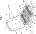
FIG. 1 is a perspective diagram showing an open state of a sample plate holder according to a first embodiment of the present disclosure; -
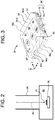
FIG. 2 is a schematic diagram showing a state in which a sample plate holder is mounted on a stage; -
FIG. 3 is a perspective diagram showing a closed state of the sample plate holder according to the first embodiment of the present disclosure; -
FIG. 4 is a perspective diagram showing an initial state of the sample plate holder according to the first embodiment of the present disclosure; -
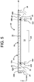
FIG. 5 is a cross-sectional diagram showing the sample plate holder according to the first embodiment of the present disclosure; -
FIG. 6 is a perspective diagram showing an open state of a sample plate holder according to a second embodiment of the present disclosure; -
FIG. 7 is a perspective diagram showing a closed state of the sample plate holder according to the second embodiment of the present disclosure; -
FIG. 8 is an exploded perspective diagram showing a sample plate holder according to a third embodiment of the present disclosure; -
FIG. 9 is a perspective diagram showing the sample plate holder according to the third embodiment of the present disclosure; -
FIG. 10 is a perspective diagram showing a sample plate holder according to a fourth embodiment of the present disclosure; and -
FIG. 11 is a perspective diagram showing a sample plate holder according to a fifth embodiment of the present disclosure. - Embodiments of the present disclosure will now be described with reference to the drawings.
-
FIGs. 1 to 5 show a sample plate holder according to a first embodiment of the present disclosure. The sample plate holder is specifically a slide glass holder for sample observation, and is placed in a sample chamber of a scanning electron microscope. The sample to be observed is, for example, pre-processed fine particles. Alternatively, fine particles including asbestos or a biological tissues in a segmented form may be set as the observation target. Alternatively, other samples may be set as the observation target. - In
FIG. 1 , asample plate holder 10 comprises aholder body 12 and acover 14. Each of these elements is formed from, for example, a metal such as stainless steel or aluminum. Alternatively, these elements may be formed from other materials. InFIG. 1 , an x direction is a first horizontal direction, a y direction is a second horizontal direction, and a z direction is a vertical direction. These three directions are orthogonal to each other. When thesample plate holder 10 is mounted on a movable stage in the sample chamber, an orientation of thesample plate holder 10 may vary depending on an orientation of the movable stage. The first horizontal direction, the second horizontal direction, and the vertical direction described above are defined assuming a case in which thesample plate holder 10 is mounted on a horizontal surface and has a basic orientation. - The
holder body 12 has a base 20 which is a horizontal plate. Athin background plate 22 is provided on an upper surface of thebase 20. Thebackground plate 22 is formed from a material which reduces or suppresses reflection of light, or a treatment for reducing or suppressing the reflection of light is applied on a surface of thebackground plate 22. Example of this treatment include plating (for example, chrome plating), rough surface machining, coloring, and the like. - The
holder body 12 hasside plates side plates holder body 12 has afront plate 28 and aback plate 30 provided respectively on one end (front end) and on the other end (back end) in the x direction. The front and back plates also have an upstanding, plate-shape form. - The inside of the
holder body 12; more specifically, a space above thebackground plate 22 and surrounded by the fourplates FIG. 1 , twosample plates sample plates FIG. 1 , illustration of the sample is omitted. - On an upper surface of each of the
sample plates sample plates sample plates sample plates - In the
holder body 12, on one side in the y direction; more specifically, near theside plate 24, there is provided aspring array 34 which functions as a first pressing-up element array. In the illustrated example configuration, thespring array 34 is formed from sixsprings 35 arranged in a straight line shape with equal spacing. In theholder 12, on the other side in the y direction; more specifically, near theside plate 26, there is provided aspring array 36 which functions as a second pressing-up element array. Similar to thespring array 34, thespring array 36 is formed from sixsprings 35 arranged in a straight line shape with equal spacing. Eachspring 35 applies a pressing-up force as an elastic force or an urging force on a sample plate contacting thespring 35. Alternatively, in place of the plurality ofsprings 35, a plurality of elastic elements may be used. - When a maximum number of the sample plates arranged in the x direction is m, and n springs are provided on each of left and right sides for each sample plate in a state in which the m sample plates are arranged, each of the
spring arrays - In the configuration exemplified in
FIG. 1 , twosample plates sample plates sample plates - In any of these cases, each sample plate is stably supported. In other words, two
spring arrays - The
side plate 24 and theside plate 26 have the same form or forms that are symmetric with each other, and the form of theside plate 24 will be described herein as a representative side plate. Theside plate 24 has anupper surface 24A which defines a reference level. Theside plate 26 has a similarupper surface 26A. Theside plate 24 has a plurality ofprojections adjacent projections projections markers markers markers markers recess 54, amarker 57 showing an intermediate position in the x direction is provided. - Each of the
markers recesses side plate 26 has a form similar to that of theside plate 24. Each of the plurality ofprojections recesses markers side plates - On a front side of the
holder body 12, alower engagement portion 32 is provided. In the illustrated example configuration, thelower engagement portion 32 is formed from twoprotrusions metal fitting 80. - The
cover 14 is rotatably held by ahinge portion 58 provided on theholder body 12. InFIG. 1 , thecover 14 has an open orientation. That is, thesample plate holder 10 is in an open state. Thecover 14 has anobservation window 60 serving as a quadrangular opening. Thecover 14 has a form surrounding theobservation window 60, and more specifically has anedge portion 62 provided on one side in the y direction and anedge portion 64 provided on the other side in the y direction of theobservation window 60. - The two
edge portions folding piece 66 is provided as a portion continuous from theedge portion 62, and afolding piece 68 is provided as a portion continuous from theedge portion 64. Thecover 14 has anupper engagement portion 70, which is formed from twoprotrusions - When the
cover 14 is in the open orientation and thesample plate holder 10 is in the open state, thesample plates springs 35 immediately below the sample plates. When thecover 14 is changed from the open orientation to a closed orientation, and thesample plate holder 10 is changed to a closed state, an inner surface (back surface) 14A of thecover 14 presses the ends of the plurality ofsample plates cover 14 is restricted when theinner surface 14A of thecover 14 abuts theupper surfaces side plates sample plates inner surface 14A of thecover 14, and the plurality ofsample plates springs 35 and thecover 14. - In this process, upper surface levels of the
sample plates cover 14; that is, a level (reference level) of the upper surfaces of the twoside plates sample plates - In the closed orientation of the
cover 14, a locked state is formed by thelower engagement portion 32 and theupper engagement portion 70. Specifically, the metal fitting 80 attached to the twoprotrusions protrusions -
FIG. 2 schematically shows a portion of a scanning electron microscope. The scanning electron microscope has asample chamber 82 and alens barrel 84.Reference numeral 90 shows an electron beam. In thesample chamber 82, a movable stage (sample stage) 86 is provided. A controller (not shown) controls a position and an orientation of themovable stage 86. Thesample plate holder 10 is mounted on themovable stage 86. -
FIG. 3 shows thesample plate holder 10 in a closed state. That is, theholder body 12 is covered by thecover 14.FIG. 3 shows a configuration in which threesample plates Respective ends sample plates edge portions cover 14. Anoverall sample region 97 including all of threeindividual sample regions observation window 60. Alock mechanism 98 is formed by thelower engagement portion 32 and theupper engagement portion 70. -
FIG. 4 shows thesample plate holder 10 in an open state.FIG. 4 shows an initial state in which no sample plate is mounted. Each of thespring arrays holder body 12 is formed from sixsprings 35. -
FIG. 5 shows a yz cross section of thesample plate holder 10. As already described, thesample plate holder 10 comprises theholder body 12, and thecover 14 covering theholder body 12. The inner surface of thecover 14 abuts theupper surfaces side plates springs 35 on thesample plate 16, but theends sample plate 16 are in contact withinner surfaces edge portions sample plate 16 is thus restricted. - A plurality of
holes 100 are formed on theholder body 12, and a plurality ofscrew members 102 are inserted into the plurality ofholes 100. The plurality ofsprings 35 are attached on upper ends of the plurality ofscrew members 102. InFIG. 5 , z0 shows the reference level, which is aligned with the inner surface level of the cover and the upper surface level of the side plate. - As described, according to the sample plate holder of the present embodiment, the upper surface levels of the sample plates can be naturally aligned at the reference level regardless of the thicknesses of the sample plates. Therefore, there can be obtained an advantage in that the focus depth does not need to be changed, or needs to be changed only slightly according to the thickness of the sample plate. In addition, there can be obtained another advantage in that a plurality of sample plates can be simultaneously held and simultaneously set inside the sample chamber, and a plurality of samples can be consecutively observed. In this process also, the focus depth does not need to be changed or needs to be changed only slightly according to the thickness of the sample plate. In the sample plate holder according to the present embodiment, regardless of the number of sample plates which are placed thereon, each of the ends of each sample plate is stably supported by two springs. On each side plate, a structure which functions as a scale is provided, and the sample plates can be accurately placed using the scale as a guide. In addition, because a treatment to suppress the light reflection is applied on the surface of the background plate, visibility of the sample plate and the sample can be improved.
-
FIGs. 6 and 7 show asample plate holder 10A according to a second embodiment of the present disclosure. InFIG. 6 , thesample plate holder 10A comprises theholder body 12 and acover 14B. Thecover 14B has theobservation window 60, and ametal mesh 104 is provided on theobservation window 60. The entirety of thesample plate holder 10A is formed from an electrically conductive material.FIG. 7 shows thesample plate holder 10A in a closed state. Thebody 12 is covered by thecover 14B. According to the second embodiment of the present disclosure, advantages can be obtained, in electron microscope observation, in that an electric field around the sample can be stabilized and in that charging of the sample can be prevented. -
FIGs. 8 and9 show asample plate holder 10B according to a third embodiment of the present disclosure. InFIG. 8 , thesample plate holder 10B comprises theholder body 12 and acover 106. Thecover 106 is formed from alower cover 108 and anupper cover 110. InFIG. 8 , for the purpose of explanation, thelower cover 108 and theupper cover 110 are illustrated in a separated state. - A
flow path structure 112 is formed on thelower cover 108. Theflow path structure 112 hasgas flow paths gas introduction port 118, and a plurality ofgas ejection ports - In
FIG. 9 , thelower cover 108 and theupper cover 110 are combined. Gas is sent from two gasejection port arrays cover 106 to a sample region 132 (refer to reference numeral 134). With this process, the sample can be set under a low-vacuum environment. That is, the inside of the sample chamber is generally set in high vacuum, and gas is locally sent so that the portion is set to low vacuum. As the gas, air, nitrogen, or the like may be used. This configuration can be applied to various sample plate holders. -
FIG. 10 shows asample plate holder 10C according to a fourth embodiment of the present disclosure. On a lower surface of theholder body 12, a combiningblock 138 formed form an insulating material is provided. The combiningblock 138 is a portion to be connected to the movable stage. On the lower surface of thebody 12, a terminal 136 is provided. The entirety of thesample plate holder 10C is formed from an electrically conductive material. A signal line is connected to the terminal 136, and a voltage is applied thereon, so that the sample plate holder, and consequently, the sample, can be set at a desired electrical potential. -
FIG. 11 shows asample plate holder 10D according to a fifth embodiment of the present disclosure. On an upper surface of thecover 14, a plurality ofalignment marks sample plate holder 10D can be positioned by reference to the alignment marks 140a, 140b, and 140c.
Claims (11)
- A sample plate holder comprising:a holder body (12) that has a storage space which can store m sample plates (16, 18) (wherein m is an integer greater than or equal to 2) arranged in an x direction;a first pressing-up element array (34) provided in the storage space on one side in a y direction orthogonal to the x direction, and formed from a plurality of pressing-up elements (35) arranged in the x direction:a second pressing-up element array (36) provided in the storage space on the other side in the y direction, and formed from a plurality of pressing-up elements (35) arranged in the x direction; anda cover (14) that covers the storage space while exposing a sample region (97) in the storage space, whereinin a state in which the m or a smaller number of the sample plates (16, 18) are stored in the storage space, pressing-up forces are applied by the first pressing-up element array (34) and the second pressing-up element array (36) on each of the sample plates (16, 18), so that an upper surface of each of the sample plates (16, 18) is pressed against an inner surface (14A) of the cover (14).
- The sample plate holder according to claim 1, wherein
each of the first pressing-up element array (34) and the second pressing-up element array (36) is formed from the m or more pressing-up elements (35) which operate independently from each other. - The sample plate holder according to claim 2, whereinm is 3, andeach of the first pressing-up element array (34) and the second pressing-up element array (36) is formed from (m x n) pressing-up elements (35) (wherein n is an integer greater than or equal to 1).
- The sample plate holder according to claim 1, further comprising:a hinge portion (58) that enables an opening movement and a closing movement of the cover (14) with respect to the holder body (12); anda lock mechanism (98) that locks the cover with respect to the holder body when the cover is in a closed state.
- The sample plate holder according to claim 1, wherein
the holder body comprises:a first side wall (24) provided on one end in the y direction; anda second side wall (26) provided on the other end in the y direction,an upper surface (24A) of the first side wall (24) and an upper surface (26A) of the second side wall (26) define a reference level, andin a closed state of the cover (14), the inner surface (14A) of the cover (14) abuts the upper surface (24A) of the first side wall (24) and the upper surface (26A) of the second side wall (26) so that an upper surface level of each of the sample plates (16, 18) is aligned at the reference level. - The sample plate holder according to claim 5, whereina first scale (38, 40, 42, 44, 52, 54, 56, 48, 50) is provided on the first side wall (24), anda second scale (38, 40, 42, 44, 52, 54, 56, 48, 50) is provided on the second side wall (26).
- The sample plate holder according to claim 1, whereineach of the sample plates (16, 18) is transparent, anda background surface (22) having an action to suppress light reflection is provided on a bottom surface of the storage space.
- The sample plate holder according to claim 1, wherein
a flow path structure (112) for blowing gas onto upper surfaces of the m or a smaller number of the sample plates (16, 18) stored in the storage space is provided on at least one of the holder body (12) or the cover (14). - The sample plate holder according to claim 1, whereinthe cover (14) has an observation window (60), andan electrically conductive mesh (104) is provided on the observation window (60).
- The sample plate holder according to claim 1, whereineach of the holder body (12) and the cover (14) is formed from an electrically conductive material,a terminal for voltage application (136) is provided on one of the holder body (12) or the cover (14), andan engagement block (138) formed from an insulating material and which is to be combined to a movable stage is provided on the holder body (12).
- The sample plate holder according to claim 1, wherein
one or a plurality of positioning marks (140a, 140b, 140c) are provided on the cover (14).
Applications Claiming Priority (1)
| Application Number | Priority Date | Filing Date | Title |
|---|---|---|---|
| JP2019162089A JP6995093B2 (en) | 2019-09-05 | 2019-09-05 | Sample plate holder |
Publications (1)
| Publication Number | Publication Date |
|---|---|
| EP3790035A1 true EP3790035A1 (en) | 2021-03-10 |
Family
ID=72290970
Family Applications (1)
| Application Number | Title | Priority Date | Filing Date |
|---|---|---|---|
| EP20193454.4A Pending EP3790035A1 (en) | 2019-09-05 | 2020-08-28 | Sample plate holder |
Country Status (4)
| Country | Link |
|---|---|
| US (1) | US11404239B2 (en) |
| EP (1) | EP3790035A1 (en) |
| JP (1) | JP6995093B2 (en) |
| CN (1) | CN112444531A (en) |
Families Citing this family (2)
| Publication number | Priority date | Publication date | Assignee | Title |
|---|---|---|---|---|
| CN114935582B (en) * | 2022-07-22 | 2022-11-04 | 季华实验室 | Fiber sample table |
| KR20260007232A (en) * | 2023-06-13 | 2026-01-13 | 주식회사 히타치하이테크 | Return container |
Citations (9)
| Publication number | Priority date | Publication date | Assignee | Title |
|---|---|---|---|---|
| JPH08254511A (en) * | 1995-03-17 | 1996-10-01 | Sony Corp | Sample holder |
| JPH09102293A (en) * | 1995-10-05 | 1997-04-15 | Jeol Ltd | Sample holder for electron microscope |
| JP2001183317A (en) * | 1999-12-24 | 2001-07-06 | Nec Corp | Sample holder for secondary ion mass spectrometer and position adjustment method thereof |
| JP2013190315A (en) * | 2012-03-14 | 2013-09-26 | Shimadzu Corp | Processed object holding mechanism and plate holder using the same |
| EP2771665A1 (en) * | 2011-10-28 | 2014-09-03 | FEI Company | Sample block holder |
| JP2015159236A (en) | 2014-02-25 | 2015-09-03 | 日本電子株式会社 | Charged particle beam drawing system |
| WO2019013633A1 (en) * | 2017-07-14 | 2019-01-17 | Hennyz B.V. | Cryotransfer system |
| JP2019128547A (en) * | 2018-01-26 | 2019-08-01 | シンフォニアテクノロジー株式会社 | microscope |
| US20190258046A1 (en) * | 2016-10-21 | 2019-08-22 | First Frontier Pty Ltd | System and method for performing automated analysis of air samples |
Family Cites Families (10)
| Publication number | Priority date | Publication date | Assignee | Title |
|---|---|---|---|---|
| JPH01135151A (en) | 1987-11-20 | 1989-05-26 | Nec Corp | Multiple address communication method |
| DE19527722A1 (en) | 1995-07-31 | 1997-02-06 | Leica Mikroskopie & Syst | Object holder for thin slides |
| US7348570B2 (en) * | 2005-12-14 | 2008-03-25 | University Of Washington | Unsupported, electron transparent films and related methods |
| US7737424B2 (en) * | 2007-06-01 | 2010-06-15 | Moxtek, Inc. | X-ray window with grid structure |
| WO2009060782A1 (en) * | 2007-11-09 | 2009-05-14 | Shin-Etsu Polymer Co., Ltd. | Retainer and substrate storing container |
| US8258473B2 (en) * | 2010-11-12 | 2012-09-04 | Nanotem, Inc. | Method and apparatus for rapid preparation of multiple specimens for transmission electron microscopy |
| JP5450357B2 (en) | 2010-11-19 | 2014-03-26 | 株式会社日立ハイテクノロジーズ | Scanning electron microscope |
| AT510799B1 (en) * | 2010-11-29 | 2012-12-15 | Leica Microsystems Schweiz Ag | MOUNTING FOR AN ELECTRONIC MICROSCOPIC SAMPLE CARRIER |
| CN105527307B (en) * | 2015-12-31 | 2018-09-25 | 大冶特殊钢股份有限公司 | A kind of specimen holder suitable for metal quality analyzer sample |
| CN206921783U (en) | 2017-04-28 | 2018-01-23 | 苏州阿特斯阳光电力科技有限公司 | A kind of Electronic Speculum platform for being used to test non-conductive sample surface topography |
-
2019
- 2019-09-05 JP JP2019162089A patent/JP6995093B2/en active Active
-
2020
- 2020-08-28 EP EP20193454.4A patent/EP3790035A1/en active Pending
- 2020-08-28 CN CN202010882849.1A patent/CN112444531A/en active Pending
- 2020-09-04 US US17/012,378 patent/US11404239B2/en active Active
Patent Citations (10)
| Publication number | Priority date | Publication date | Assignee | Title |
|---|---|---|---|---|
| JPH08254511A (en) * | 1995-03-17 | 1996-10-01 | Sony Corp | Sample holder |
| JPH09102293A (en) * | 1995-10-05 | 1997-04-15 | Jeol Ltd | Sample holder for electron microscope |
| JP2001183317A (en) * | 1999-12-24 | 2001-07-06 | Nec Corp | Sample holder for secondary ion mass spectrometer and position adjustment method thereof |
| EP2771665A1 (en) * | 2011-10-28 | 2014-09-03 | FEI Company | Sample block holder |
| JP2013190315A (en) * | 2012-03-14 | 2013-09-26 | Shimadzu Corp | Processed object holding mechanism and plate holder using the same |
| JP2015159236A (en) | 2014-02-25 | 2015-09-03 | 日本電子株式会社 | Charged particle beam drawing system |
| US20150303027A1 (en) * | 2014-02-25 | 2015-10-22 | Jeol Ltd. | Charged-Particle Beam Lithographic System |
| US20190258046A1 (en) * | 2016-10-21 | 2019-08-22 | First Frontier Pty Ltd | System and method for performing automated analysis of air samples |
| WO2019013633A1 (en) * | 2017-07-14 | 2019-01-17 | Hennyz B.V. | Cryotransfer system |
| JP2019128547A (en) * | 2018-01-26 | 2019-08-01 | シンフォニアテクノロジー株式会社 | microscope |
Also Published As
| Publication number | Publication date |
|---|---|
| JP6995093B2 (en) | 2022-01-14 |
| US11404239B2 (en) | 2022-08-02 |
| JP2021039916A (en) | 2021-03-11 |
| US20210074507A1 (en) | 2021-03-11 |
| CN112444531A (en) | 2021-03-05 |
Similar Documents
| Publication | Publication Date | Title |
|---|---|---|
| US4436385A (en) | Specimen holder for inverted microscopes | |
| US11404239B2 (en) | Sample plate holder | |
| EP3381656A1 (en) | Glass screen film applicator and carrier module thereof | |
| US7291847B2 (en) | Specimen tip and tip holder assembly | |
| US7180662B2 (en) | Stage assembly and method for optical microscope including Z-axis stage and piezoelectric actuator for rectilinear translation of Z stage | |
| US6479807B1 (en) | Microscope | |
| US3680947A (en) | Microscope apparatus with movable fluid bearing object support | |
| EP3244196B1 (en) | Objective optical system for atr measurement | |
| US11562886B2 (en) | Ion milling apparatus and sample holder | |
| JP3409222B2 (en) | Sample holding device | |
| CN101692417A (en) | Control method of platform | |
| JP4784931B2 (en) | Sample holding mechanism and sample processing / observation device | |
| KR20200052362A (en) | A method for providing a multi-aperture imaging device, a multi-aperture imaging system and a multi-aperture imaging device having a low installation height and a switchable viewing direction | |
| EP1921483A1 (en) | Stage device | |
| US11679489B2 (en) | Sample chip worktable and retainer | |
| JP7042497B2 (en) | Device for insertion into imaging system | |
| KR20130025382A (en) | System for testing semiconductors | |
| US7375351B2 (en) | Micro-column electron beam apparatus | |
| JP4251456B2 (en) | Total reflection sample illumination device and illumination method | |
| US9202739B2 (en) | Holder for semiconductor wafers and flat substrates | |
| CN218272909U (en) | Slide glass limiting and fixing device | |
| CN215218011U (en) | An optical path switching component with a simple structure and high repeatability and positioning accuracy | |
| CN220064502U (en) | Sample clamp for microscope image acquisition | |
| US20250146915A1 (en) | System for clamping and aligning a fluidic chip to a tissue section | |
| WO2019092138A1 (en) | Microscope stage |
Legal Events
| Date | Code | Title | Description |
|---|---|---|---|
| PUAI | Public reference made under article 153(3) epc to a published international application that has entered the european phase |
Free format text: ORIGINAL CODE: 0009012 |
|
| STAA | Information on the status of an ep patent application or granted ep patent |
Free format text: STATUS: THE APPLICATION HAS BEEN PUBLISHED |
|
| AK | Designated contracting states |
Kind code of ref document: A1 Designated state(s): AL AT BE BG CH CY CZ DE DK EE ES FI FR GB GR HR HU IE IS IT LI LT LU LV MC MK MT NL NO PL PT RO RS SE SI SK SM TR |
|
| AX | Request for extension of the european patent |
Extension state: BA ME |
|
| STAA | Information on the status of an ep patent application or granted ep patent |
Free format text: STATUS: REQUEST FOR EXAMINATION WAS MADE |
|
| 17P | Request for examination filed |
Effective date: 20210506 |
|
| RBV | Designated contracting states (corrected) |
Designated state(s): AL AT BE BG CH CY CZ DE DK EE ES FI FR GB GR HR HU IE IS IT LI LT LU LV MC MK MT NL NO PL PT RO RS SE SI SK SM TR |
|
| STAA | Information on the status of an ep patent application or granted ep patent |
Free format text: STATUS: EXAMINATION IS IN PROGRESS |
|
| 17Q | First examination report despatched |
Effective date: 20240423 |