EP3790023A1 - Procédé d'analyse de données d'images médicales dans une collaboration virtuelle à plusieurs utilisateurs, programme informatique, interface utilisateur et système - Google Patents
Procédé d'analyse de données d'images médicales dans une collaboration virtuelle à plusieurs utilisateurs, programme informatique, interface utilisateur et système Download PDFInfo
- Publication number
- EP3790023A1 EP3790023A1 EP19195018.7A EP19195018A EP3790023A1 EP 3790023 A1 EP3790023 A1 EP 3790023A1 EP 19195018 A EP19195018 A EP 19195018A EP 3790023 A1 EP3790023 A1 EP 3790023A1
- Authority
- EP
- European Patent Office
- Prior art keywords
- user
- image data
- medical image
- workspace
- visualization
- Prior art date
- Legal status (The legal status is an assumption and is not a legal conclusion. Google has not performed a legal analysis and makes no representation as to the accuracy of the status listed.)
- Withdrawn
Links
Images


Classifications
-
- G—PHYSICS
- G16—INFORMATION AND COMMUNICATION TECHNOLOGY [ICT] SPECIALLY ADAPTED FOR SPECIFIC APPLICATION FIELDS
- G16H—HEALTHCARE INFORMATICS, i.e. INFORMATION AND COMMUNICATION TECHNOLOGY [ICT] SPECIALLY ADAPTED FOR THE HANDLING OR PROCESSING OF MEDICAL OR HEALTHCARE DATA
- G16H80/00—ICT specially adapted for facilitating communication between medical practitioners or patients, e.g. for collaborative diagnosis, therapy or health monitoring
-
- G—PHYSICS
- G06—COMPUTING; CALCULATING OR COUNTING
- G06T—IMAGE DATA PROCESSING OR GENERATION, IN GENERAL
- G06T19/00—Manipulating 3D models or images for computer graphics
- G06T19/006—Mixed reality
-
- G—PHYSICS
- G06—COMPUTING; CALCULATING OR COUNTING
- G06F—ELECTRIC DIGITAL DATA PROCESSING
- G06F3/00—Input arrangements for transferring data to be processed into a form capable of being handled by the computer; Output arrangements for transferring data from processing unit to output unit, e.g. interface arrangements
- G06F3/01—Input arrangements or combined input and output arrangements for interaction between user and computer
- G06F3/011—Arrangements for interaction with the human body, e.g. for user immersion in virtual reality
- G06F3/012—Head tracking input arrangements
-
- G—PHYSICS
- G06—COMPUTING; CALCULATING OR COUNTING
- G06F—ELECTRIC DIGITAL DATA PROCESSING
- G06F3/00—Input arrangements for transferring data to be processed into a form capable of being handled by the computer; Output arrangements for transferring data from processing unit to output unit, e.g. interface arrangements
- G06F3/01—Input arrangements or combined input and output arrangements for interaction between user and computer
- G06F3/011—Arrangements for interaction with the human body, e.g. for user immersion in virtual reality
- G06F3/014—Hand-worn input/output arrangements, e.g. data gloves
-
- G—PHYSICS
- G06—COMPUTING; CALCULATING OR COUNTING
- G06F—ELECTRIC DIGITAL DATA PROCESSING
- G06F3/00—Input arrangements for transferring data to be processed into a form capable of being handled by the computer; Output arrangements for transferring data from processing unit to output unit, e.g. interface arrangements
- G06F3/01—Input arrangements or combined input and output arrangements for interaction between user and computer
- G06F3/017—Gesture based interaction, e.g. based on a set of recognized hand gestures
-
- G—PHYSICS
- G06—COMPUTING; CALCULATING OR COUNTING
- G06T—IMAGE DATA PROCESSING OR GENERATION, IN GENERAL
- G06T17/00—Three dimensional [3D] modelling, e.g. data description of 3D objects
- G06T17/10—Constructive solid geometry [CSG] using solid primitives, e.g. cylinders, cubes
-
- G—PHYSICS
- G06—COMPUTING; CALCULATING OR COUNTING
- G06T—IMAGE DATA PROCESSING OR GENERATION, IN GENERAL
- G06T7/00—Image analysis
- G06T7/0002—Inspection of images, e.g. flaw detection
- G06T7/0012—Biomedical image inspection
-
- G—PHYSICS
- G16—INFORMATION AND COMMUNICATION TECHNOLOGY [ICT] SPECIALLY ADAPTED FOR SPECIFIC APPLICATION FIELDS
- G16H—HEALTHCARE INFORMATICS, i.e. INFORMATION AND COMMUNICATION TECHNOLOGY [ICT] SPECIALLY ADAPTED FOR THE HANDLING OR PROCESSING OF MEDICAL OR HEALTHCARE DATA
- G16H30/00—ICT specially adapted for the handling or processing of medical images
- G16H30/20—ICT specially adapted for the handling or processing of medical images for handling medical images, e.g. DICOM, HL7 or PACS
-
- G—PHYSICS
- G16—INFORMATION AND COMMUNICATION TECHNOLOGY [ICT] SPECIALLY ADAPTED FOR SPECIFIC APPLICATION FIELDS
- G16H—HEALTHCARE INFORMATICS, i.e. INFORMATION AND COMMUNICATION TECHNOLOGY [ICT] SPECIALLY ADAPTED FOR THE HANDLING OR PROCESSING OF MEDICAL OR HEALTHCARE DATA
- G16H30/00—ICT specially adapted for the handling or processing of medical images
- G16H30/40—ICT specially adapted for the handling or processing of medical images for processing medical images, e.g. editing
-
- A—HUMAN NECESSITIES
- A61—MEDICAL OR VETERINARY SCIENCE; HYGIENE
- A61B—DIAGNOSIS; SURGERY; IDENTIFICATION
- A61B17/00—Surgical instruments, devices or methods, e.g. tourniquets
- A61B2017/00017—Electrical control of surgical instruments
- A61B2017/00216—Electrical control of surgical instruments with eye tracking or head position tracking control
-
- A—HUMAN NECESSITIES
- A61—MEDICAL OR VETERINARY SCIENCE; HYGIENE
- A61B—DIAGNOSIS; SURGERY; IDENTIFICATION
- A61B90/00—Instruments, implements or accessories specially adapted for surgery or diagnosis and not covered by any of the groups A61B1/00 - A61B50/00, e.g. for luxation treatment or for protecting wound edges
- A61B90/36—Image-producing devices or illumination devices not otherwise provided for
- A61B90/361—Image-producing devices, e.g. surgical cameras
- A61B2090/3612—Image-producing devices, e.g. surgical cameras with images taken automatically
-
- A—HUMAN NECESSITIES
- A61—MEDICAL OR VETERINARY SCIENCE; HYGIENE
- A61B—DIAGNOSIS; SURGERY; IDENTIFICATION
- A61B90/00—Instruments, implements or accessories specially adapted for surgery or diagnosis and not covered by any of the groups A61B1/00 - A61B50/00, e.g. for luxation treatment or for protecting wound edges
- A61B90/36—Image-producing devices or illumination devices not otherwise provided for
- A61B2090/364—Correlation of different images or relation of image positions in respect to the body
- A61B2090/365—Correlation of different images or relation of image positions in respect to the body augmented reality, i.e. correlating a live optical image with another image
-
- A—HUMAN NECESSITIES
- A61—MEDICAL OR VETERINARY SCIENCE; HYGIENE
- A61B—DIAGNOSIS; SURGERY; IDENTIFICATION
- A61B90/00—Instruments, implements or accessories specially adapted for surgery or diagnosis and not covered by any of the groups A61B1/00 - A61B50/00, e.g. for luxation treatment or for protecting wound edges
- A61B90/36—Image-producing devices or illumination devices not otherwise provided for
- A61B90/37—Surgical systems with images on a monitor during operation
- A61B2090/372—Details of monitor hardware
-
- A—HUMAN NECESSITIES
- A61—MEDICAL OR VETERINARY SCIENCE; HYGIENE
- A61B—DIAGNOSIS; SURGERY; IDENTIFICATION
- A61B90/00—Instruments, implements or accessories specially adapted for surgery or diagnosis and not covered by any of the groups A61B1/00 - A61B50/00, e.g. for luxation treatment or for protecting wound edges
- A61B90/50—Supports for surgical instruments, e.g. articulated arms
- A61B2090/502—Headgear, e.g. helmet, spectacles
-
- G—PHYSICS
- G06—COMPUTING; CALCULATING OR COUNTING
- G06T—IMAGE DATA PROCESSING OR GENERATION, IN GENERAL
- G06T2207/00—Indexing scheme for image analysis or image enhancement
- G06T2207/10—Image acquisition modality
- G06T2207/10072—Tomographic images
- G06T2207/10081—Computed x-ray tomography [CT]
-
- G—PHYSICS
- G06—COMPUTING; CALCULATING OR COUNTING
- G06T—IMAGE DATA PROCESSING OR GENERATION, IN GENERAL
- G06T2207/00—Indexing scheme for image analysis or image enhancement
- G06T2207/10—Image acquisition modality
- G06T2207/10072—Tomographic images
- G06T2207/10104—Positron emission tomography [PET]
Definitions
- the present invention relates to a method for analyzing medical image data in a virtual multi-user collaboration, a computer program related to the method, a user interface used in the method and a system configured to perform the method.
- Medical imaging techniques provide three-dimension (3D) - or even four-dimensional (4D) - medical image data of the human or animal body.
- the image data is usually viewed and analyzed on two-dimensional (2D) screens. Therefore, there is an omnipresent risk to misinterpret the relative spatial relationships between anatomical structures represented on medical image data provided in 3D or 4D, when the medical image data is analyzed and interpreted on 2D screens.
- 3D or 4D two-dimensional
- VR Virtual Reality
- Existing multi-user VR applications are avatar-based in which several users can be in the same scene at the same time to, e.g., manipulate a model of an object.
- a VR framework can support multiple simultaneous users operating in the same virtual space using a client-server model, where one user operates as the server and has control over the system display.
- the VR environment for each user is driven by an individual network computer connected to the user's headset.
- Each client computer has access to a copy of the data to be displayed, which can be either on a local drive or a shared network drive.
- the server listens for clients on a TCP/IP port and then establishes a network connection with each client.
- the server will routinely transmit a small data object that contains viewing state information, which each client uses to update its display.
- This object includes data necessary to synchronize the view, such as rotation, scale, volume position, and cutting plane.
- Each client transmits pose information for its headsets and controllers to the server, which broadcasts these to the other clients for display. Models of the headsets and controllers for the other users in the system are rendered in each individual client view. This enables users to interact directly with each other and also helps to avoid real-world collisions between users operating in a shared physical space.
- Dieter Schmalieri discloses in "Bridging Multiple User Interface Dimensions with Augmented Reality" an experimental user interface system, which uses collaborative augmented reality to incorporate true 3D interaction into a productivity environment. This concept is extended to bridge multiple user interface dimensions by including multiple users, multiple host platforms, multiple display types, multiple concurrent applications, and a multi-context (i.e., 3D document) interface into a heterogeneous distributed environment. Contexts encapsulate a live application together with 3D (visual) and other data, while locales are used to organize geometric reference systems. By separating geometric relationships (locales) from semantic relationships (contexts), one achieves a great amount of flexibility in the configuration of displays. Multiple users are working on separate hosts.
- 3D-windows 3D-windows
- They can share contexts, but can layout the context representations (3D-windows) arbitrarily according to screen format and personal preferences. This is made possible by defining separate locales, as the position of 3D-windows is not shared across locale boundaries. In other words, one shared object can be viewed by multiple users from different perspectives.
- EP 3496046 A1 concerns a method for displaying medical image data on at least one display medium for a group of at least two interactive viewers, having the steps of providing medical image data which contain at least one 3D or 4D image data set of a specific examination area of a patient; and providing a possibility for displaying the medical image data in an interactive, virtual environment, wherein each interactive viewer has its own virtual position. Further, each interactive viewer can change his/her virtual position and optionally his/her viewing angle independently of the other viewers.
- a selectable part of the individual work can be automatically shared among the users.
- the invention is directed to a method for analyzing medical image data in a virtual multi-user collaboration, wherein the medical image data is analysed by at least two users, each user having his/her own workspace, wherein the workspace is a XR-workspace. the method including the steps of:
- XR stands for X reality or Cross Reality, which is a generic term comprising at least Virtual Reality (VR), Augmented Reality (AR), Mixed Reality (MR), and Cinematic Reality (CR).
- XR maybe defined as a technology-implemented experience of a virtual environment, often combined with real world objects, or a combination of a real world environment combined with virtual environments or objects.
- X Reality encompasses a wide spectrum of hardware and software, including sensory interfaces, applications, and infrastructures, that enable content creation for virtual reality (VR), mixed reality (MR), augmented reality (AR), cinematic reality (CR). With these tools, users generate new forms of reality by bringing digital objects into the physical world and bringing physical world objects into the digital world.
- XR is used here to refer to various technologies including VR, AR or MR.
- a computer-generated visualisation providing a truly three-dimensional experience of the depicted structures is implemented, in particular by using screens or glasses showing a slightly different image to each eye.
- the user may often interact with the XR by gestures and other movements, e.g. walk around in the XR and grab virtual objects.
- the XR of the invention may provide in particular visual feedback, but may also allow other types of sensory feedback, such as auditory or haptic feedback to a user.
- VR the real environment is usually not visible to the user, it is completely overlaid with a virtual world.
- This effect is commonly created by VR headsets consisting of a head-mounted display with a small screen in front of the eyes, but can also be created through specially designed rooms with multiple large screens.
- a person using virtual reality equipment is able to look around the artificial world, move around in it, and interact with virtual features or items.
- MR Mixed reality
- AR virtual reality
- AR AR
- AR AR
- virtual objects are superposed (i.e. overlaid) over the real environment.
- This effect may be created by special glasses such as Microsoft HoloLens which allows the user to see the real environment, but which also uses cameras to form a 3D model of such real environment so that virtual objects can be overlaid over the real environment via the glasses.
- MR or AR may include the real environment as a background in front of which the visualization is displayed.
- two users present in the same room and each wearing AR glasses may interact with each other in the real world and in the AR, while both users have their own individual view of the medical image data (i.e. each user has his/her own visualisation of the medical image data).
- the visualisation may be an effigy (i.e. an image) of a real object (e.g. a human or animal heart). That is, the visualisation may be a model representing the real object, wherein parameters of the visualisation may be changed with respect to the real object (e.g. the size, contrast, colour, partly enlarged regions etc.).
- the technique of volume ray casting may be used. In this technique, a ray is generated for each desired image pixel. Using a simple camera model, the ray starts at the centre of protection of the camera (usually the viewing position or eye point) and passes through the image pixel on an imaginary image plane floating between the camera and the volume to be rendered.
- the ray is sampled at regular or adapted intervals throughout the volume.
- the data is interpolated at each sample point, a transfer function applied to form an RGBA sample, the result added onto the accumulated RGBA of the ray, and the process repeated until the ray exits the volume.
- the process is repeated for every pixel on the screen to form the completed visualization.
- the medical image data maybe visualized using volume rendering.
- the volume rendering of the visualisation may be performed by techniques described in " The Visualization Handbook", edited by Charles H. Hansen and Christopher R. Johnson, Elsevier Butterworth Heinemann 2005 , especially in the Chapter “Overview of Volume Rendering” by Arie Kaufmann starting on p. 127, and which is incorporated herein by reference.
- the XR may be realised by presenting stereo images to the user, i.e. each eye sees a different image, so that the brain will put together the two different images to a true three-dimensional scene.
- binocular images may be presented on any XR display, such as a VR headset, AR glasses or a multi-projected environment, or a screen showing the two images intermittently, in connection with shutter glasses.
- the visualization may be displayed by stereoscopic rendering: Therein, the visualisation is calculated twice, for two viewing positions having a slight spatial offset, i.e. one viewing position for the left eye and one for the right eye. When the two thus calculated visualisations are shown to the user one on each eye, e.g.
- the user gains a truly three-dimensional (VR) impression.
- VR three-dimensional
- the XR enables the user using the XR to "look around" the artificial world, move around in it, and interact with virtual objects, features or items.
- the effect is commonly created by XR headsets comprising a head-mounted display with a small screen in front of each eye, but can also be created through specially designed rooms with multiple large screens.
- position and orientation information have to be transmitted by the headset to the electronic device (e. g. computer) generating the XR, so that the visualisation is moving in coherence with head movements of the user.
- the medical image data may be dynamically rendered (e.g. volume rendered or surface rendered) so as to be visualized in each XR-workspace as the visualization.
- volume rendering may be based on spatial intensity data (i.e. voxel data). Depending on the resolution of the medical image data there may be an intensity data for each point in space or for a region in space.
- intensity data i.e. voxel data
- each available image data information is rendered, which results in a considerable high computing capacity that is needed.
- surface rendering only one "layer” (i.e. the visible surface) is rendered, wherein the image data existing behind the layer is not rendered.
- the surface rendered medical image data may be a computer graphical model consisting of a plurality of triangular shaped surfaces.
- both techniques may be combined such that a region of interest may be rendered using the method of volume rendering and peripheral regions may be rendered using the method of surface rendering.
- the medical image data maybe visualized using a volume rendered object which has the advantage that it is suitable for more complex anatomies or highly individual structures like valve leaflet cusps, stenosis, calcifications, bio-protheses, ruptured chordae etc.
- the medical image data may be visualized using a dynamic, computer-generated model of at least a part of an anatomical structure.
- models have the advantages that they show a simpler version/abstraction of the anatomy, make it easier to navigate and interpret the anatomy, and are not very much dependent on the medical image data quality.
- the model i.e.
- the simplification of the anatomical structure may be a triangulated surface model of a particular interface within the anatomical structure, for example the blood-tissue interface of a blood vessel or a heart chamber.
- the model may comprise a number of points spanning a line or a surface for each frame. It may also be a mathematical model, for example a parametrised model, such as a surface or volume spanned by spline curves.
- the model is dynamic, i.e. it follows the movement of the anatomical structure across the time period.
- the purpose of the dynamic model is to visualise at least a part of the anatomical structure, for example one or several chambers of the moving heart, without obstructing the view of the user with too much detail.
- the 3D visualization of the dynamic 3D model is typically a rendering of a dynamic shape or surface model, wherein the rendering may be done by techniques available from computer graphics, including shading, ray casting, ambient occlusion etc..
- the volume rendering may be performed by any volume rendering technique known in the art for example as described in US 2005/0253841 A1 , incorporated herein by reference.
- the medical image data may include information of an anatomical structure which may be an organ or part of an organ of the human or animal body such as heart, but may be also a blood vessel or a bone structure.
- the medical image data may include a 3D scatter plot including points within a 3D coordinate system, wherein each point has its own x, y and z component within the 3D coordinate system.
- the medical image data may include digital image data e.g. in DICOM standard i.e. containing a three-dimensional array of voxels, each voxel containing a grey scale value.
- Such medical data may be obtained from a field of view containing the dynamic anatomical structure using a medical imaging modality such as MR, computed tomography (CT), position emission tomography (PET), or ultrasound (US).
- a medical imaging modality such as MR, computed tomography (CT), position emission tomography (PET), or ultrasound (US).
- CT computed tomography
- PET position emission tomography
- US ultrasound
- the anatomical structure is the heart
- ultrasound and in particular three-dimensional echocardiography may be advantageously used.
- the different medical image data may be derived from ultrasound images having different frequencies, computed tomography having different acceleration voltages or images including contrast medium or not.
- the medical image data may include 4D medical image data, wherein the fourth dimension is time.
- One 3D image from the time sequence of 3D images forming a 4D medical image may also be called a "frame" in the following.
- 4D medical image data includes the visualization of 3D images across time, which means that a sequence of visualizations is shown dynamically, at a frame rate of e.g. 60-100 visualizations per second. That is, 4D medical image data may be visualized as animated movie (i.e. in a cine-mode) so as to visualize the operation of a thorax of a patient, for example. If, 4D medical image data are visualized, the sequence may be rendered in a movie-like manner.
- the 3D images may be acquired with a frame rate of e.g. 5 - 100, preferably more than30 images per second, so as to allow a smooth representation of the dynamically moving anatomical structure.
- Medical image data may include further medical and/or administrative information e.g. information of the patient, the currently executed therapy etc.. Medical image data may include several image data which are preferably registered to each other in space, so they can be overlaid with each other, each user may select which one should be displayed in his/her workspace.
- the medical imaging modality may be capable of attaining up to 30 volumes per second (i.e. medical image data representing a region under inspection), therefore, the rendered 3D object maybe updated each time new medical image data are available. In other words, the rendered 3D object maybe dynamically updated. This is particularly useful, if a patient is simultaneously examined while the collaboration takes place, in cases in which the patient is in an emergency, for example.
- each user shares the same medical image data with all other users.
- the result of the analyzing process is also shared by all other users because the result is coupled to the medical image data shared by all users.
- the visualization displayed in each workspace may be individually changed by a user so as to attain an individual view of the medical image data.
- the medical image data and the result of the analyzing process are identical and shared by all users, wherein the display of this content (i.e. the visualization of the medical image data and the result) is subjected to the user himself/herself.
- each user has the maximum freedom to inspect the medical image data as he/she wants, while at the same time the result of the analyzing process of other users is displayed in his/her personalized visualization (i.e. in his/her individual view of the medical image data) in real-time.
- the medical image data and the result of the analyzing process are decoupled from the visualisation of the medical image data in each workspace.
- each user has his/her individual view of the medical image data, while at the same time the medical image data and the result are the same for all users.
- the user maybe a participant in the collaboration session, specifically a doctor, for example, an interdisciplinary heart team (IHT) may use the present invention, wherein the teams may consist of an interventional cardiologist, cardiovascular surgeon, care/nurse coordinator, OR/Cath lab nurse, imaging specialist, cardiac anaesthesiologist.
- IHT interdisciplinary heart team
- Each user uses his/her own XR workspace. Alternately, at least two users may share the same workspace, for instance in a scenario in which one user is the teacher and another user is a student.
- Each of the XR-workspace may be physically connected to another XR-workspace via cable or wireless.
- Each workspace may have an own personal computer including a processor.
- Each computer may work as a client-computer.
- at least some of the workspaces may be part of one client-computer. That is, XR workspaces may be located at different locations or may be in the same room, for example.
- the step of allowing each user to individually and independently from each other change the visualization in a user" s own XR workspace is executed in such a way that none of the other users notices how the visualization (i.e. the individual view of the medical image data) is changed in another XR workspace.
- a viewing position and a viewing direction in space may be changed.
- the position or orientation of a plane cutting through the 3D medical image data (herein referred to as "cutplane”) may be individually adjusted, as well as the mode of displaying such plane in the visualization.
- the user may select one of several so-called "cutplane" modes: In one mode, no cutplane is displayed, in another, the cutplane cuts through a 3D image volume and is overlaid over the image content. In another mode, the cutplane displays a corresponding multi planar reconstruction (MPR) of the 3D image data. Further, the opacity and colour of the visualisation may be changed.
- visualization parameters of the visualization may be changed, e.g. volume rendering parameters. Specifically, the visualization parameters may include thresholds, opacity, contrast etc. Further, the visualization may be adjusted "live", that is, with an immediate effect while watching the visualization.
- the result of the analyzing process is synchronized in real-time with the at least one other workspace such that each workspace displays the result of the analyzing process in the respective individual visualization of the medical image data.
- the synchronization in this case means the transmission of data attained in the analyzing process from the respective workspace to the shared medical image data. That is, the results of the analyzing process are visible to all other users at the same time as they are made.
- each of the other users may see the results in their own individual visualization of the medical image data. For example, each user sees the annotations of the other users live in his own visualisation of the medical image data. This makes "handing over" the medical image data between multiple users obsolete and therefore results in fewer interactions between users and a faster sharing of measurement results and annotations.
- the execution of the analyzing process may include the selection of a plane in the visualization.
- the process then preferably comprises a step of displaying a multi planar reconstruction (MPR) of the selected plane of the visualization, in particular at the position in the three-dimensional visualisation environment corresponding to the selected plane.
- MPR multi planar reconstruction
- a multi planar reconstruction is an image reconstructed from several original image planes.
- CT for example, a stack of usually transversal images is acquired.
- the user may measure the diameter of the mitral valve and accordingly select the best fitting valve from a library.
- an MPR is created by e.g.
- the result of the analyzing process may be at least one measurement result of features of the visualization of the medical image data such as distances, diameters, thicknesses etc.
- the measurement result may be displayed by a first dot at a first location from which a distance is to be measured (starting point) and a second dot at a second location to which the distance is to be measured (end point) and a line connecting the first dot and the second dot.
- the result of the analyzing process may be three-dimensional notes such as a 3D freehand line that maybe drawn by a user within his/her workspace.
- the result of the analyzing process may be no planar objects but 3D objects that extends in any one of the three dimensions within the 3D coordinate system. For example, the user may retrace the flow of blood through a heart or follow the course of the coronary arteries.
- the first aspect of the present invention provides the advantage that each user can generate his/her own preferred visualization of the medical image data, in other words, each user has his/her own individual view of the medical image data. Further, each user may analyse and view the visualization of the medical image data in his own way (e.g. individual viewing directions, cutplane positions, thresholds and speed), that is, some users may need more time for specific procedures as compared to other users. Since there is no avatar in the visualization, there is no occurrence of hiding parts of the medical image data behind such avatars. In addition, unexperienced user may follow results made by another user in real-time in order to better understand a subject matter they will not understand by themselves.
- his own way e.g. individual viewing directions, cutplane positions, thresholds and speed
- the XR provides the advantage that the user may view and analyse the visualization with great confidence, since he obtains a truly three-dimensional view of the anatomical structure represented by the medical image data. Further, since he can walk around it and possibly even into it, he can have the visualised object (e.g. the visualisation of the human heart) displayed in huge magnification, so as to completely fill the space in front of the user. Therefore, the user has a particularly good overview and may take measurements with great accuracy. Further, the handling of user input events is particularly easy and intuitive in XR. Actions such as rotating the objects and/or adjusting the settings of the visualization, which may be quite tricky on a two-dimensional screen, are very intuitive and fast in a XR preferably using XR controllers.
- the medical image data include images, preferably 4D images, of a human heart.
- the invention may find particular use in planning minimally invasive heart surgery, such as surgery on a heart valve or a heart valve replacement.
- New minimally invasive methods like transcatheter valve replacement can be used for patients who were formerly considered inoperable and/or not suited for open-heart surgery.
- Some transcatheter valve replacements e.g. TAVR
- TAVR transcatheter valve replacements
- LVOT left ventricular outflow tract
- ViV valve-in-valve
- a dysfunctional valve - sometimes a bioprosthetic mitral valve - is replaced by a new valve in a minimally invasive ViV procedure.
- the new valve is positioned inside the old valve, replacing the old valve while it unfolds. Therefore, it is crucial that the valve should be positioned correctly and have the correct size.
- the new mitral valve does not obstruct the LVOT. Therefore, for valve in valve intervention planning, the medical image data contains the mitral valve, the LVOT and the left ventricle.
- the displaying of the result of the analyzing process may be selectively and individually enabled and disabled by a user in his/her workspace.
- Each result of the analyzing process may be positioned at a specific position within the 3D coordinate system (i.e. the position may be defined by x, y and z coordinates) in which the medical image data is defined. That is, the result may be located at a specific position in relation to the medical image data. Because the medical image data and the result are shared by all users, the result is displayed within each workspace regardless in which way the user has individually changed the visualization (i.e. his/her individual view of the medical image data). The result may be visualized by relatively thin lines such that it is less likely that the result covers other objects displayed in the workspace. Nevertheless, there may be a situation in which the result covers a part of the visualization and/or other results. Therefore, according to the embodiment of the present invention, the result may be disabled so as to vanish and provide a free view onto objects positioned behind the result.
- each user may have a different focus with respect to a region of interest, it is important that each user may individually decide which result hinders a sufficient view onto the region of interest and thus shall be disabled. That is, each user may selectively disable results made by himself/herself or other users. Further, enabling or disabling the result may have no influence on the other at least one workspace such that the enabling and disabling of the result may be executed independently in each workspace.
- the method may allow a user to adjust the transparency of the result so as to see objects placed behind the result through the result. Particularly, once the result is disabled, a user may enable the result again so as to again see the result within his/her workspace. For this reason, the result, in a disabled state, maybe indicated by a small arrow or similar to provide the user with the information where the result was originally placed. As a result, the user may easily regain the result for enabling the same again.
- the visualization in each workspace may be further individualized in that each user may individually adjust both the visualization (i.e. the individual view of the medical image data) and the result exactly in a way that satisfies his/her requirements with respect to workability.
- the at least one workspace may be an AR-workspace. That is, both the visualization and the result are displayed in the workspace while the real environment is still visible as a background of the workspace.
- the real environment may be the surrounding area of the user (e.g. an operating room or a doctor's office).
- at least one visualisation parameter within the AR-workspace in particular a transparency and/or a colour of the visualization of the medical image data and/or the result of the analyzing process may be adjusted automatically, so as to allow the user to view the visualization of the medical image data and/or the result of the analyzing process superposed on the real environment with a target contrast.
- visualisation parameters may be values defining the way in which the medical image data and/or the result is/are visualized. Therefore, by changing these values the visualization also changes accordingly.
- the visualisation parameters may include the transparency value, that is, the value of lucency of an object. For example, if an object has a low transparency the region covered by the object is not visible. On the other hand, if the object has high transparency the region covered by the object might be at least slightly visible.
- visualisation parameters may include the colour of the visualization, that is, the hue or tone of the visualization. In more detail, hue is one of the main properties (also called colour appearance parameter) of a colour.
- Hue can typically be represented quantitatively by a single number, often corresponding to an angular position around a central or neutral point or axis on a colour space coordinate diagram (such as a chromaticity diagram) or colour wheel, or by its dominant wavelength or that of its complementary colour.
- the other colour appearance parameters are colorfulness, saturation (also known as intensity or chroma), lightness, and brightness.
- these parameters may be automatically adjusted in order to attain the target contrast within the workspace.
- the target contrast may be also referred to as an optimal contrast.
- the contrast within the workspace may be defined as the difference between the brightest point and the darkest point within the workspace, wherein within the AR-workspace the real environment is considered, too.
- the contrast within the workspace may be also defined as the contrast ratio or dynamic range.
- the visualization of the medical image data and/or the result may be adjusted in such a way that the contrast within the AR-workspace amounts to the target contrast.
- the target contrast may be a predefined value, which is defined as being most appropriate with respect to detectability and conspicuousness of the visualisation.
- the target contrast maybe individually adjusted and/or set by the user so as to satisfy his/her personal predilection.
- each workspace may have its own virtual environment in which the visualization of the medical image data and the result of the analyzing process are displayed.
- the virtual environment may be the background in which the visualization is displayed.
- the method may further include the step of allowing each user to individually and independently adjust a visualization parameter of the virtual environment so as to adjust a contrast within the workspace, preferably by setting a transparency and/or a colour of the virtual environment.
- the virtual environment may be the background in front of which the visualization is positioned.
- the virtual environment may be the surrounding which surrounds the visualization.
- the virtual environment may include a coloured surface that has a defined colour and brightness so as to provide a pleasant working environment for the user.
- the virtual environment may be adjusted so as to provide a contrast within the workspace that amounts to the target contrast.
- the user may individually adjust the virtual environment.
- the real environment is also visible as a background within the workspace.
- the AR-workspace may have a virtual environment that has a specific transparency so as to provide the possibility for the user to see the real environment, too.
- the value of transparency of the virtual environment may be adjustable so as to shadow a very bright real environment such that the contrast within the workspace amounts to the target contrast. This is particularly useful when the AR-workspace is used in a relatively bright environment such as an operating room.
- the virtual environment of an AR-workspace allows the user to automatically adapt the AR-workspace to conditions of the real environment while still offering the possibility to recognize the real environment.
- the AR-workspace may be easily adapted to varying light conditions of the real environment. As a result, the AR-workspace is appropriately usable regardless of the light conditions of the real environment.
- the virtual environment may include at least one virtual control element.
- the virtual control element may be a slide bar and/or a button.
- the control element may be used to execute steps of the method e.g. changing the visualisation and/or to implement further administrative processes like saving an image, loading medical image data, communicate with other users etc.
- the control element may provide a drop-down menu in which several predefined control commands may be listed.
- the step of allowing each user to individually and independently change the visualization of the medical image data may include the use of a VR controller in order for the user to interact with virtual features in the workspace. Specifically, in order to execute the change of the visualization using hand gestures, preferably by grabbing an object in the workspace.
- a VR controller in order to execute the change of the visualization using hand gestures, preferably by grabbing an object in the workspace.
- a user wearing a XR headset and holding at least one controller in one hand (preferably a controller in each hand) sees in the controller together with the visualisation.
- the controller may be a hand held device including further operating elements e.g. buttons, track ball, touchpad, etc..
- an indication e.g.
- a virtual controller of the controller within the VR-workspace may be depicted so as to inform the user where the controller is positioned within the VR-workspace.
- the XR workspace provides the possibility for the user to move the controllers towards the visualisation, grab it by pressing a particular button, and move and/or rotate the visualised object with the movement of his hands, like he would with a real-world object.
- the users have 18 degrees of freedom (six degrees of freedom, namely three rotational and three translational degrees of freedom for each of the XR headset and the two controllers) to correctly and intuitively view and analyse the visualised object.
- a movement of the controller may be tracked and a correspondent movement of the indication is visualized within the VR-workspace.
- the real controller may be still visible.
- a virtual controller may be visualized in order to improve the conspicuity of the controller.
- the position information may be attained by at least one sensor e.g. an acceleration sensor located within the controller. More commonly, the position(s) and/or orientation(s) of the controller(s) is/are tracked by the cameras on the VR headset.
- the data outputted by the sensor or camera may be inputted to a processor that processes the data so as to control the commands executed by operations of the controller and the visualization of the virtual controller. Further, dependent on the output of the sensor the processor may determine whether a gesture is performed slow or fast. Further, a rotation movement may be detected. As a result, the processor may perform processes accordingly.
- Operations executed by the controller may include zoom in/zoom out the visualisation, scale down/ scale up the visualisations within the workspace, adjust visualisation parameters and rendering settings/parameters, and/or grab the displayed objects, in particular the visualisation of the medical image data.
- the controller may receive hand gestures made by the user, for example, a grabbing gesture, a zoom-in gesture (approaching of two fingers), zoom-out gesture (departing of two fingers) a wipe gesture etc..
- the visualization may be virtually grabbed using the controller and rotated or moved, for example.
- the real controller may be visualized as a virtual controller allowing a user at least to grab and move an object within the workspace by hand gestures. "Move" in this context may also mean rotate.
- the controller may also allow a user the change the size and/or shape of objects within the workspace, specifically, of the visualization.
- the controller as described above allows a user to change any one or several of the position, size, shape and/or orientation of the visualization.
- the position and/or orientation of the visualization may be adjusted (i.e. the individual view of the medical image data).
- the size of the visualization may be changed to better analyse the visualization.
- adjustments are made by using the controller by grabbing the visualization, and changing its position, size and/or orientation by hand gestures, as one would a real-world object.
- a controller allows a user to adjust parameters by means of gesture control. For example, the user selects a certain parameter by touching it using hand movement in the XR workspace.
- Suitable parameters are related to the visualisation and may be selected from a volume rendering threshold, smoothing, lighting intensity, size, opacity of a visualised object, starting and holding the cine-mode etc.
- the user may intuitively operate within the AR/VR-workspace like moving objects or operate operation elements such that the efficiency of such collaborations is increased.
- the workspace may comprise a lamp which the user may grab and move within the workspace, so as to influence the lighting of the visualization.
- the brightness of the scene in particular the brightness of a movable lamp, may be adjusted. Further, by adjusting the position of the lamp, the direction in which the visualization is illuminated may be changed. This is particularly useful in order to illuminate cavities of the visualized anatomy.
- the step of allowing each user to individually and independently change the visualization of the medical image data includes manipulating the visualization so as to rotate the visualization, cut away a part of the visualization, change rendering parameters of the visualization, change image settings of the visualization, change a contrast of the visualization, change voxel intensity thresholds of the visualization and/or change a size of the visualization.
- the visualisation is manipulated e.g. is rotated if the user wants to see another part or region of the visualization. That is, each user has his/her own individual view of the medical image data. In the same way each user may individually cut away a part of the visualisation in order to attain a visualisation in which only the parts of the visualization are displayed that are of interest for the specific user.
- the rendering parameters of the visualization may include the kind of rendering (i.e. volume rendering and/or surface rendering) and the image settings may include a colour of surfaces and shading options (i.e. the position of a light source in the space).
- a user may set settings of his individual visualization such that the medical image data is visualized in slices or in other forms.
- there may be presets of different visualizations in which the medical image data are displayed such as, a plan view, a right front view, a left front view a rear view, button view and a perspective view. The presets may be set in advance or may be predefined by each user.
- At least one user may adopt the change(s) of the visualization of the medical image data made by another user. That is, by adopting the visualization of another user (i.e. the individual view of the medical image data), the visualization is transferred to at least one other user's workspace such that at least two users have the same individual view of the medical image data.
- This procedure may be particularly useful, if there is an experienced user (e.g. teacher) who currently explains something to other users (e.g. to students).
- the other user may be in a position to learn from the more experienced user.
- the other user(s) is/are provided with the same individual view of the medical image data as the experienced user.
- the switch from one individual view to another one may be continuously executed so as to show the user in which way the individual view is changed.
- the switch between the individual views may be illustrated by visualizing the switch in a bird's-eye view, that is, the change between the both individual views is illustrated in a top view.
- one user may force at least one other user to adopt his/her change(s) of the visualization of the medical image data. That is, the user may force other users to see exactly that what he/she sees (i.e. having the same individual view), this may be specifically appropriate in courses in which one user wants to show other users a specific part of the workflow. Therefore, the efficiency of the collaboration is improved.
- only one user is allowed to decide which change(s) of the visualization of the medical image data may be shared with other users (i.e. the user may be the presenter and/or teacher), whereas the other users have restricted functionalities and may not be allowed to share any change(s) of the visualization of the medical image data (e.g. the users may be participants and/or students).
- the step of allowing at least one user to execute an analyzing process of the medical image data in his/her workspace may further include taking 3D measurements, executing MPR-mode and/or inserting annotation. That is, the result of the analyzing process may be one or more annotation(s) related to specific aspects of the visualisation such as background information of previously executed therapies, comments of users related to an abnormality etc..
- Each result may be visualized by thin lines within each of the workspaces in real time because the result belongs to the medical image data that is shared by all users. That is, immediately after the results have been obtained, each user sees the result in his individual view.
- the 3D measurements may be a measurement in the 3D dimensional space, that is, a distance between two points which differ from each other in each of the x-coordinate, y-coordinate and the z-coordinate. Further, a 3D measurement may involve tracing a non-planar, irregularly shaped object, for example by measuring the distance spanned by several points in space, for example points along an irregularly shaped object such as the mitral annulus. Such non-planar measurements cannot be performed on a 2D screen, but can easily be done in the XR workspace of the invention.
- MPR-mode may be a multi-planar reconstruction which is a method of two-dimensional image reconstruction.
- frontal, sagittal, oblique or curved sections are calculated from transversal sections and displayed to help the user with anatomical orientation.
- Oblique sections for example, are helpful in heart imaging (four-chamber view, short axis sections), curved reconstructions along structures that are themselves curved several times for the representation of vessels (such as the coronary arteries) or ureters.
- the medical image data e.g. obtained by CT
- a small layer thickness should be selected to avoid step artifacts during image reconstruction.
- the image noise may be reduced by summing up several layers. Thresholding may be an adaption of the threshold boundaries of each voxel in order to better visualize the region of interest.
- the step of allowing at least one user to execute the analyzing process of the medical image data in his/her workspace may further include positioning at least one model of a medical device, specifically an implant, within the visualization of the medical image data so as to determine its operational position.
- the model of a medical device may be a computer graphical object. That is, the model of a medical device may be additionally displayed within the XR-workspace.
- the medical device maybe an implant or any other device that is to be placed within the human or animal body.
- the computer graphical object is for example a representation of geometric data, e.g. a 3D structure defined by vertices, such as a polyhedron.
- the computer graphical object is preferably locked to the movement of the anatomical structure, i.e.
- the processor controlling the visualisation remembers the relative position and orientation of the medical device with regard to the visualisation and will keep this relative position and orientation.
- the medical device represents a new valve
- such new valve can be locked to the movement of the valve annulus, e.g. the mitral annulus.
- this may be done using 3D speckle.
- the valve may be optimally positioned in its operational position (i.e. in its optimal position), thereby avoiding or limiting any obstruction of an outflow.
- the user may use the controllers to move and tilt the computer graphical object in relation to the visualisation.
- the user can not only measure, but also "try out" a selected implant or implant size, for example a replacement valve, to see if it fits the anatomical feature, e.g. the mitral valve.
- a selected implant or implant size for example a replacement valve
- the user may select the best fitting valve from a library and place the valve - or rather the computer graphical object corresponding the valve - inside the visualisation for an initial inspection.
- the computer graphical object corresponds to a CAD model of the medical device, e.g. the CAD model used in the design and/or production of the medical device, or more preferably to a simplified model thereof, for example a simplified model a heart valve.
- the computer graphical object looks similar to what the medical device will look like on interventional X-ray images (fluoroscopy images), because minimally invasive interventions are almost always done under fluoroscopy control.
- the computer graphical object is preferably three-dimensional, it may be e.g. be a simplified model of an implant, for example in the form of a wire mesh or an object defined by a set of simple surfaces.
- the operational position of the model of the medical device is determined by visualizing the medical device dynamically in operation, preferably in combination with the 4D image information.
- the 4D medical image data i.e. a sequence of 3D medical image date e.g. in the cine-mode
- the model of the medical device e.g. the artificial mitral valve
- the dynamic movement of the medical device may be based on tracked 4D image data. For example, specific landmarks interacting with the medical device are tracked over the sequence of 3D image data, and the virtual position of the medical device is adjusted accordingly. Subsequently, the user may investigate how the specific model of the medical device works in combination with the specific anatomical structures under inspection.
- the present invention provides a location-independent XR collaboration tool that provides an interconnected communication concept in which the medical image data and results of an analyzing process are shared by all users whereas each user still has his/her own individual view of the medical image data (i.e. his/her own duplicate/visualization of the medical image data) within his/her own workspace.
- a computer program including the features of claim 12.
- the computer program comprising program code instructions, which, when executed by a processor, enables the processor to carry out the above method.
- the computer program may be in any code, in particular a code suited for computer graphic applications, in particular for XR programming.
- a computer-readable medium comprising the above-defined computer program may be provided.
- the computer-readable medium may be any digital storage device, such as a USB-stick, hard disk, CD-ROM, SD card or SSD card.
- the computer program need not be stored on such a computer-readable medium to be supplied to costumer, but may be downloadable via the internet.
- the method according to the invention is executed by a processor which may be incorporated in any electronic device able to control a display, in particular a XR display such as a XR headset or projection display.
- a display in particular a XR display such as a XR headset or projection display.
- Such digital device may be a computer, PC, server, television set, tablet computer, smartphone, laptop, hand-held device or the like.
- the processor may also be part of a cloud computer, workstation, or the control console of a medical image device, in particular an ultrasound scanner.
- a user interface configured to be used in executing an above-defined method, wherein the user interface includes:
- a user interface is for example a system comprising at least a screen or display and usually input elements, e.g. a XR controller, and/or buttons or sliders, allowing a user to interact with the content of the display e.g. by adjusting visualisation parameters/settings, zooming, annotating and/or moving or tilting the visualisation.
- input elements e.g. a XR controller
- buttons or sliders allowing a user to interact with the content of the display e.g. by adjusting visualisation parameters/settings, zooming, annotating and/or moving or tilting the visualisation.
- the commands may further include individually and independently adjusting a contrast within the workspace of the user, preferably by setting a transparency and/or a colour of the virtual environment.
- a system for analyzing medical image data in a virtual multi-user collaboration including: a processor configured to carry out the above-defined method, and at least two above-defined user interfaces that are connected to the processor.
- the virtual reality environment may be realized using commercially available VR equipment, such as the HTC VIVE Pro Virtual Reality System, which includes a VR headset, two VR controllers, two position trackers and (made by HTC Corporation, Taoyuan City 330, Taiwan) or the Oculus Rift S (Oculus, Facebook Technologies, LLC).
- This headset does not require separate position trackers in the room, since the position tracking function is provided by the headset itself.
- FIG. 1 illustrates the structure of the human heart 1.
- the blood coming from the lungs flows into the left atrium 2 and from there through the mitral valve 3 into the left ventricle 4. From there, it is pumped through the aortic valve 5 into the aorta 6. This part is also termed left ventricular outflow tract (LVOT).
- LVOT left ventricular outflow tract
- the blood coming from the body flows into the right atrium 7 and is pumped through the tricuspid valve 8 into the right ventricle 9. From there, it is pumped through the pulmonary valve 10 into the pulmonary artery 11.
- Heart wall 12 is made of muscular tissue surrounding the heart chambers 2, 4, 7 and 9.
- the heart 1 in Fig. 1 represents an example of 3D medical image data achieved by MR, computed tomography (CT), position emission tomography (PET), ultrasound (US), or transoesophageal echocardiography (TEE).
- CT computed tomography
- PET position emission tomography
- US ultrasound
- TEE transoesophageal echocardiography
- the time is used as the fourth dimension.
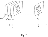
- FIG. 2 shows a schematic representation of a sequence of ultrasound images M 1 , M 2 , M 3 , ... Mz of the heart 1 based on medical image data.
- Z is the number of images acquired during one heart cycle, i.e. in time T, wherein T is about 0.5 to 1.5 seconds.
- the figure shows two-dimensional images, however, according to the present invention a three-dimensional image and is acquired at each point in time t i .
- a three-dimensional medical image may be formed by a stack of two-dimensional images.
- a four-dimensional medical image may be formed by a plurality of three-dimensional medical images that are consecutive displayed in a sequence.
- Such sequence of images M 1 , M 2 , M 3 , ... Mz may be acquired for example by echocardiography of the moving heart, for example with a TEE probe.
- the sequence of medical images M 1 , M 2 , M 3 , ... M Z represent the 4D medical image data.
- an interdisciplinary heart team plans a heart surgery and is supposed to discuss a complex aspect previous to the actual surgery.
- the team scheduled a virtual multi-user collaboration.
- the IHT consists of: an interventional cardiologist C, a cardiac anesthesiologist A, an OR/cath lab nurse N and a cardiac surgeon S.
- Fig. 3 schematically shows the principle of the virtual multi-user collaboration according to the embodiment of the present invention.
- each participant/user has his/her own workspace WS.
- the 3D or 4D medical image data 34 is provided and loaded so as to be visualized in each workspace 30.
- an individual visualization 32 of the medical image data 34 is generated and provided for each workspace.
- each user has his/her own individual view 32 of the medical image data 34.
- each of the users starts to work with the visualization.
- each user changes the visualization so as to satisfy his/her requirements for analyzing the visualisation of the medical image data 34.
- each user has his/her own isolated copy 32 of the visualization of the medical image data 34 and can resize, rotate, translate and set image settings using a controller 36. None of this handling/view settings part is transferred to any other user.
- the interventional cardiologist C prefers to show the visualization approximately 40 cm sized and 50 cm away from his head, a high threshold set so that leaflets of the mitral valve 4 disappear and a viewing direction from left atrium 2 through mitral valve 4 into left ventricle 4.
- the cardiac anesthesiologist A prefers to show the visualization as large as possible (100-120 cm) such that he/she can move his/her head into the visualization, a lower threshold set so that the leaflets are easily visible and a viewing direction from the side and in two-chamber view.
- the OR/cath lab nurse N and the cardiac surgeon S prefers further individual views onto the visualisation. This changing of the visualisation 32 is carried out individually and independently by each user so as to obtain an individual visualization (i.e. an individual view of the medical image data). It is to be noted, that none of the users sees the changes of the individual view of the medical image data executed by the other users.
- the visualization which is based on the medical image data is automatically updated. That is, in each workspace 30 the visualization is updated based on the medical image data that are shared by all users. Another reason why new medical image data are available is because a patient's organ is simultaneously analysed while at the same time the collaboration takes place and the acquired data are directly provided, in case the patient is an emergency, for example. Further, each user sees in his/her workspace 30 on which version of the medical image data the visualization is based. In addition, each user may individually change between different versions of visualizations.
- each user executes the analyzing process in his/her workspace 30 while having the individual view of the medical image data. That is, each user makes his/her own measurements/annotations which are results of the analyzing process within his/her own workspace 30 using the controller.
- each user controls the medical image data in that he/she adds the result of the analyzing process via his/her own workspace 30 directly into the medical image data.
- the measurements/annotations inputted via the controller are transmitted to the medical image data shared by all users. Consequently, each user sees the measurements/annotations of the other users live within his/her own visualization of the medical image data. As a result, each user may immediately see and receive measurements/annotations of the other users a potentially use them for his/her own approach.
- the same image dataset appears for all 4 users simultaneously.
- Each user (C, A, N and S) makes his own measurements and annotations.
- Each user sees the annotations of the other users live at his own visualisation of the image dataset.
- the cardiologist C and the surgeon S may have different ideas about which procedure is right, but the anaesthesiologist A, after seeing both approaches, has another idea that combines the approaches of S and N in a meaningful way.
- S and N will make different measurements and annotations, both of which can be seen by A.
- A may thus annotate his improved proposal on his own visualisation of the image dataset. Every user sees his new annotation live on his own model/visualisation and agrees. Thereby, a more efficient meeting of an interdisciplinary heart is possible.
- the measurements/annotations may hide or cover a part of the visualization in a workspace 30 of another user. Therefore, if in one user's workspace 30 a part of the visualization is hided and/or covers, the user may disable the respective measurement/annotation. Alternatively, the user may adjust the measurement/annotation so as to be transparent.
- the sharing of measurements/annotations is faster and each user has an unrestricted view on the region of interest regardless of how many participants are in the VR session.
- individual understanding of anatomy differs, differently perceived reference points and structures in the medical 3D datasets inevitably lead to interobserver variability, different measurement (procedures), different assumptions and different interpretations of anatomical correlations.
- these phenomena is avoided because each user may individually change the visualization in that way, he/she prefers to work.
- the user now sees his and the changes of the other users live in his individual view, which he can handle and adjust according to his personal viewing preferences.
- At least one workspace 30 is an AR workspace.
- the procedure is the same as that of the previous embodiment with the exception that the user sees both the visualization and the real environment, wherein the real environment forms a background for the visualization.
- the AR-workspace in this embodiment, has a virtual environment that is interposed between the visualization and the real environment.
- the real environment may be shadowed by increasing the opacity of the virtual environment.
- the AR-workspace 30 may automatically set the opacity/transparency of the virtual background so as to provide the target contrast within the workspace 30.
- the AR workplace is particularly useful when the user interacts with a person (e.g. a patient) in the real environment at the same time.
- the virtual environment is automatically adapted to varying light conditions.
- each user may individually adjust the virtual environment in order to satisfy his/her own requirements and/or preferences.
- users can synchronize their individual view with another user, for example a teacher showing a critical measurement or positioning of a medical device to a classroom of students. That is, the individual view 32 towards the visualization is shared with another one or multiple participant of the collaboration.
- a user can put himself in the optimal viewing position and watch other (e.g., more experienced) users live and in real 3D while they make certain measurements, annotations or position device like artificial heart valves within the visualization to determine their optimal position.
- the "Teacher" can first observe (from the student's view) how the student would do a certain annotation/measurement and then synchronize the individual view of one or multiple students with his own individual view, e.g.
- the user interface is a VR interface, as shown in FIG. 4 .
- Such interface is realised by a virtual reality headset 82 worn by a user 80.
- the headset 82 is connected to a computer 72, either through a cable or through wireless connection.
- Such virtual reality headset 82 includes internal displays, separate for each eye, as well as position sensors 84 which track the movement of the head.
- Such headset may also include cameras, in case an augmented reality environment is to be presented.
- the user 80 is holding VR controllers 86 in his hands, wherein the controllers 86 also include position sensors (not shown) as well as buttons or other input elements.
- Such virtual reality controller 86 allows a user to grab and move an object displayed in the virtual reality environment 50.
- the VR headset may for example be an HTC VIVE headset and corresponding VR controllers.
- FIG. 5 shows a flow diagram illustrating the method according to an embodiment of the invention.
- medical image data including 3D or 4D image information showing e.g. the moving heart are provided.
- the 4D medical image data are provided the sequence spanning a time period corresponding to one heartbeat.
- the medical image data is loaded into the workspace 30 of each user so as to simultaneously display a visualization of the medical image data to each user, for example by generating a volume rendered or a surface rendered visualization.
- each user is allowed to individually and independently from each other change the visualization of the medical image data, so as to obtain an individual visualization (i.e. his/her individual view of the medical image data) of the medical image data in each workspace 30 pertaining to each user.
- step 96 at least one user is allowed to execute an analyzing process of the medical image data in his/her workspace 30.
- Such analyzing process includes making measurements and annotations which are positioned within the 3D coordinate system.
- step 98 the result of the analyzing process is displayed in the workspace 30 in which the analyzing process was carried out.
- step 100 the result of the analyzing process is synchronized in real-time with the at least one other workspace 30 such that each workspace 30 displays the result of the analyzing process in the respective individual visualization of the medical image data.
- the steps 96 to 100 are executed simultaneously, that is, the measurements and annotations made in step 96 are directly visibly in each of the workspaces because the measurements and annotations are directly implemented in the medical image data 34 shared by each user.
Priority Applications (6)
| Application Number | Priority Date | Filing Date | Title |
|---|---|---|---|
| EP19195018.7A EP3790023A1 (fr) | 2019-09-03 | 2019-09-03 | Procédé d'analyse de données d'images médicales dans une collaboration virtuelle à plusieurs utilisateurs, programme informatique, interface utilisateur et système |
| CN202080061842.1A CN114391158A (zh) | 2019-09-03 | 2020-08-28 | 用于在虚拟多用户协作中分析医学图像数据的方法、计算机程序、用户接口和系统 |
| JP2022513881A JP2022547450A (ja) | 2019-09-03 | 2020-08-28 | 仮想マルチユーザコラボレーションにおいて医用画像データを分析するための方法、コンピュータプログラム、ユーザインターフェース、およびシステム |
| EP20761846.3A EP4026143A1 (fr) | 2019-09-03 | 2020-08-28 | Procédé d'analyse de données d'images médicales dans une collaboration virtuelle multi-utilisateur, programme informatique, interface utilisateur et système |
| CA3152809A CA3152809A1 (fr) | 2019-09-03 | 2020-08-28 | Procede d'analyse de donnees d'images medicales dans une collaboration virtuelle multi-utilisateur, programme informatique, interface utilisateur et systeme |
| PCT/EP2020/074132 WO2021043684A1 (fr) | 2019-09-03 | 2020-08-28 | Procédé d'analyse de données d'images médicales dans une collaboration virtuelle multi-utilisateur, programme informatique, interface utilisateur et système |
Applications Claiming Priority (1)
| Application Number | Priority Date | Filing Date | Title |
|---|---|---|---|
| EP19195018.7A EP3790023A1 (fr) | 2019-09-03 | 2019-09-03 | Procédé d'analyse de données d'images médicales dans une collaboration virtuelle à plusieurs utilisateurs, programme informatique, interface utilisateur et système |
Publications (1)
| Publication Number | Publication Date |
|---|---|
| EP3790023A1 true EP3790023A1 (fr) | 2021-03-10 |
Family
ID=67847595
Family Applications (2)
| Application Number | Title | Priority Date | Filing Date |
|---|---|---|---|
| EP19195018.7A Withdrawn EP3790023A1 (fr) | 2019-09-03 | 2019-09-03 | Procédé d'analyse de données d'images médicales dans une collaboration virtuelle à plusieurs utilisateurs, programme informatique, interface utilisateur et système |
| EP20761846.3A Pending EP4026143A1 (fr) | 2019-09-03 | 2020-08-28 | Procédé d'analyse de données d'images médicales dans une collaboration virtuelle multi-utilisateur, programme informatique, interface utilisateur et système |
Family Applications After (1)
| Application Number | Title | Priority Date | Filing Date |
|---|---|---|---|
| EP20761846.3A Pending EP4026143A1 (fr) | 2019-09-03 | 2020-08-28 | Procédé d'analyse de données d'images médicales dans une collaboration virtuelle multi-utilisateur, programme informatique, interface utilisateur et système |
Country Status (5)
| Country | Link |
|---|---|
| EP (2) | EP3790023A1 (fr) |
| JP (1) | JP2022547450A (fr) |
| CN (1) | CN114391158A (fr) |
| CA (1) | CA3152809A1 (fr) |
| WO (1) | WO2021043684A1 (fr) |
Cited By (1)
| Publication number | Priority date | Publication date | Assignee | Title |
|---|---|---|---|---|
| WO2023278343A1 (fr) * | 2021-06-29 | 2023-01-05 | Arterys Inc. | Systèmes et procédés de présentation d'images médicales dans de multiples contextes |
Families Citing this family (1)
| Publication number | Priority date | Publication date | Assignee | Title |
|---|---|---|---|---|
| CN113456220B (zh) * | 2021-06-30 | 2023-02-28 | 上海微创医疗机器人(集团)股份有限公司 | 对准方法、手术机器人及计算机存储介质 |
Citations (3)
| Publication number | Priority date | Publication date | Assignee | Title |
|---|---|---|---|---|
| US20050253841A1 (en) | 2004-05-17 | 2005-11-17 | Stefan Brabec | Volume rendering processing distribution in a graphics processing unit |
| US20140033052A1 (en) * | 2008-07-10 | 2014-01-30 | Real View Imaging Ltd. | Man machine interface for a 3d display system |
| EP3496046A1 (fr) | 2018-02-13 | 2019-06-12 | Siemens Healthcare GmbH | Procédé d'affichage des informations d'image tridimensionnelle médicale |
-
2019
- 2019-09-03 EP EP19195018.7A patent/EP3790023A1/fr not_active Withdrawn
-
2020
- 2020-08-28 CA CA3152809A patent/CA3152809A1/fr active Pending
- 2020-08-28 EP EP20761846.3A patent/EP4026143A1/fr active Pending
- 2020-08-28 CN CN202080061842.1A patent/CN114391158A/zh active Pending
- 2020-08-28 WO PCT/EP2020/074132 patent/WO2021043684A1/fr unknown
- 2020-08-28 JP JP2022513881A patent/JP2022547450A/ja active Pending
Patent Citations (3)
| Publication number | Priority date | Publication date | Assignee | Title |
|---|---|---|---|---|
| US20050253841A1 (en) | 2004-05-17 | 2005-11-17 | Stefan Brabec | Volume rendering processing distribution in a graphics processing unit |
| US20140033052A1 (en) * | 2008-07-10 | 2014-01-30 | Real View Imaging Ltd. | Man machine interface for a 3d display system |
| EP3496046A1 (fr) | 2018-02-13 | 2019-06-12 | Siemens Healthcare GmbH | Procédé d'affichage des informations d'image tridimensionnelle médicale |
Non-Patent Citations (4)
| Title |
|---|
| "The Visualization Handbook", 2005, ELSEVIER BUTTERWORTH HEINEMANN |
| ARIE KAUFMANN: "Overview of Volume Rendering", pages: 127 |
| DAVID W. SHATTUCK: "VR-frameworkfor multiuser virtual reality environment for visualizing neuroimaging data", HEALTHCARE TECHNOLOGY LETTERS, 13 August 2018 (2018-08-13) |
| KLAUS ENGEL, TEXTURE-BASED VOLUME VISUALIZATION FOR MULTIPLE USERS ON THE WORLD WIDE WEB |
Cited By (1)
| Publication number | Priority date | Publication date | Assignee | Title |
|---|---|---|---|---|
| WO2023278343A1 (fr) * | 2021-06-29 | 2023-01-05 | Arterys Inc. | Systèmes et procédés de présentation d'images médicales dans de multiples contextes |
Also Published As
| Publication number | Publication date |
|---|---|
| CA3152809A1 (fr) | 2021-03-11 |
| WO2021043684A1 (fr) | 2021-03-11 |
| JP2022547450A (ja) | 2022-11-14 |
| CN114391158A (zh) | 2022-04-22 |
| EP4026143A1 (fr) | 2022-07-13 |
Similar Documents
| Publication | Publication Date | Title |
|---|---|---|
| US10592067B2 (en) | Distributed interactive medical visualization system with primary/secondary interaction features | |
| JP2022017422A (ja) | 拡張現実感手術ナビゲーション | |
| JP6336930B2 (ja) | 仮想オブジェクト表示装置、方法、プログラムおよびシステム | |
| WO2016132822A1 (fr) | Dispositif, procédé, programme et système d'affichage d'objet virtuel | |
| US20220387128A1 (en) | Surgical virtual reality user interface | |
| Pinter et al. | SlicerVR for medical intervention training and planning in immersive virtual reality | |
| EA027016B1 (ru) | Система и способ компьютерного моделирования медицинской процедуры | |
| EP3497600B1 (fr) | Système de visualisation médicale interactif distribué ayant des caractéristiques d'interface utilisateur | |
| US20220130046A1 (en) | Method of visualizing a dynamic anatomical structure | |
| CA3152809A1 (fr) | Procede d'analyse de donnees d'images medicales dans une collaboration virtuelle multi-utilisateur, programme informatique, interface utilisateur et systeme | |
| US20200205905A1 (en) | Distributed interactive medical visualization system with user interface and primary/secondary interaction features | |
| KR101903996B1 (ko) | 의료 영상 시뮬레이션 방법 및 그 방법을 이용한 장치 | |
| US20230230321A1 (en) | Extended reality-based user interface add-on, system and method for reviewing 3d or 4d medical image data | |
| RU2808612C2 (ru) | Способ визуализации динамической анатомической структуры | |
| Grandi et al. | Spatially aware mobile interface for 3d visualization and interactive surgery planning | |
| EP4160543A1 (fr) | Procédé d'analyse de données d'images médicales 3d, programme informatique et dispositif d'évaluation de données d'images médicales 3d | |
| Pinter et al. | SlicerVR for image-guided therapy planning in immersive virtual reality | |
| Gallo et al. | User-friendly inspection of medical image data volumes in virtual environments | |
| Mukit | Intraoperative Virtual Surgical Planning Through Medical Mixed Reality | |
| Sutherland et al. | Augmented and Virtual Reality in Medicine | |
| CN118043851A (en) | Method for analyzing 3D medical image data, computer program and 3D medical image data evaluation device | |
| WO2023211838A1 (fr) | Systèmes et procédés pour faciliter des actes médicaux avec présentation d'un nuage de points 3d | |
| CN116057604A (zh) | 用于虚拟医学模型的视觉分析的协作系统 |
Legal Events
| Date | Code | Title | Description |
|---|---|---|---|
| PUAI | Public reference made under article 153(3) epc to a published international application that has entered the european phase |
Free format text: ORIGINAL CODE: 0009012 |
|
| STAA | Information on the status of an ep patent application or granted ep patent |
Free format text: STATUS: THE APPLICATION HAS BEEN PUBLISHED |
|
| AK | Designated contracting states |
Kind code of ref document: A1 Designated state(s): AL AT BE BG CH CY CZ DE DK EE ES FI FR GB GR HR HU IE IS IT LI LT LU LV MC MK MT NL NO PL PT RO RS SE SI SK SM TR |
|
| AX | Request for extension of the european patent |
Extension state: BA ME |
|
| STAA | Information on the status of an ep patent application or granted ep patent |
Free format text: STATUS: THE APPLICATION IS DEEMED TO BE WITHDRAWN |
|
| 18D | Application deemed to be withdrawn |
Effective date: 20210911 |