EP3789982A1 - Roadside information processing system - Google Patents
Roadside information processing system Download PDFInfo
- Publication number
- EP3789982A1 EP3789982A1 EP18921448.9A EP18921448A EP3789982A1 EP 3789982 A1 EP3789982 A1 EP 3789982A1 EP 18921448 A EP18921448 A EP 18921448A EP 3789982 A1 EP3789982 A1 EP 3789982A1
- Authority
- EP
- European Patent Office
- Prior art keywords
- information
- roadside
- edge
- processing unit
- vehicle
- Prior art date
- Legal status (The legal status is an assumption and is not a legal conclusion. Google has not performed a legal analysis and makes no representation as to the accuracy of the status listed.)
- Granted
Links
Images


Classifications
-
- G—PHYSICS
- G08—SIGNALLING
- G08G—TRAFFIC CONTROL SYSTEMS
- G08G1/00—Traffic control systems for road vehicles
- G08G1/01—Detecting movement of traffic to be counted or controlled
- G08G1/0104—Measuring and analyzing of parameters relative to traffic conditions
- G08G1/0108—Measuring and analyzing of parameters relative to traffic conditions based on the source of data
- G08G1/0112—Measuring and analyzing of parameters relative to traffic conditions based on the source of data from the vehicle, e.g. floating car data [FCD]
-
- B—PERFORMING OPERATIONS; TRANSPORTING
- B60—VEHICLES IN GENERAL
- B60W—CONJOINT CONTROL OF VEHICLE SUB-UNITS OF DIFFERENT TYPE OR DIFFERENT FUNCTION; CONTROL SYSTEMS SPECIALLY ADAPTED FOR HYBRID VEHICLES; ROAD VEHICLE DRIVE CONTROL SYSTEMS FOR PURPOSES NOT RELATED TO THE CONTROL OF A PARTICULAR SUB-UNIT
- B60W40/00—Estimation or calculation of non-directly measurable driving parameters for road vehicle drive control systems not related to the control of a particular sub unit, e.g. by using mathematical models
- B60W40/02—Estimation or calculation of non-directly measurable driving parameters for road vehicle drive control systems not related to the control of a particular sub unit, e.g. by using mathematical models related to ambient conditions
- B60W40/04—Traffic conditions
-
- B—PERFORMING OPERATIONS; TRANSPORTING
- B60—VEHICLES IN GENERAL
- B60W—CONJOINT CONTROL OF VEHICLE SUB-UNITS OF DIFFERENT TYPE OR DIFFERENT FUNCTION; CONTROL SYSTEMS SPECIALLY ADAPTED FOR HYBRID VEHICLES; ROAD VEHICLE DRIVE CONTROL SYSTEMS FOR PURPOSES NOT RELATED TO THE CONTROL OF A PARTICULAR SUB-UNIT
- B60W40/00—Estimation or calculation of non-directly measurable driving parameters for road vehicle drive control systems not related to the control of a particular sub unit, e.g. by using mathematical models
- B60W40/02—Estimation or calculation of non-directly measurable driving parameters for road vehicle drive control systems not related to the control of a particular sub unit, e.g. by using mathematical models related to ambient conditions
- B60W40/06—Road conditions
- B60W40/072—Curvature of the road
-
- G—PHYSICS
- G08—SIGNALLING
- G08G—TRAFFIC CONTROL SYSTEMS
- G08G1/00—Traffic control systems for road vehicles
- G08G1/01—Detecting movement of traffic to be counted or controlled
- G08G1/0104—Measuring and analyzing of parameters relative to traffic conditions
- G08G1/0108—Measuring and analyzing of parameters relative to traffic conditions based on the source of data
- G08G1/0116—Measuring and analyzing of parameters relative to traffic conditions based on the source of data from roadside infrastructure, e.g. beacons
-
- G—PHYSICS
- G08—SIGNALLING
- G08G—TRAFFIC CONTROL SYSTEMS
- G08G1/00—Traffic control systems for road vehicles
- G08G1/01—Detecting movement of traffic to be counted or controlled
- G08G1/0104—Measuring and analyzing of parameters relative to traffic conditions
- G08G1/0125—Traffic data processing
- G08G1/0133—Traffic data processing for classifying traffic situation
-
- G—PHYSICS
- G08—SIGNALLING
- G08G—TRAFFIC CONTROL SYSTEMS
- G08G1/00—Traffic control systems for road vehicles
- G08G1/01—Detecting movement of traffic to be counted or controlled
- G08G1/0104—Measuring and analyzing of parameters relative to traffic conditions
- G08G1/0137—Measuring and analyzing of parameters relative to traffic conditions for specific applications
- G08G1/0141—Measuring and analyzing of parameters relative to traffic conditions for specific applications for traffic information dissemination
-
- G—PHYSICS
- G08—SIGNALLING
- G08G—TRAFFIC CONTROL SYSTEMS
- G08G1/00—Traffic control systems for road vehicles
- G08G1/01—Detecting movement of traffic to be counted or controlled
- G08G1/056—Detecting movement of traffic to be counted or controlled with provision for distinguishing direction of travel
-
- G—PHYSICS
- G08—SIGNALLING
- G08G—TRAFFIC CONTROL SYSTEMS
- G08G1/00—Traffic control systems for road vehicles
- G08G1/09—Arrangements for giving variable traffic instructions
- G08G1/0962—Arrangements for giving variable traffic instructions having an indicator mounted inside the vehicle, e.g. giving voice messages
- G08G1/0967—Systems involving transmission of highway information, e.g. weather, speed limits
- G08G1/096766—Systems involving transmission of highway information, e.g. weather, speed limits where the system is characterised by the origin of the information transmission
- G08G1/096783—Systems involving transmission of highway information, e.g. weather, speed limits where the system is characterised by the origin of the information transmission where the origin of the information is a roadside individual element
-
- H—ELECTRICITY
- H04—ELECTRIC COMMUNICATION TECHNIQUE
- H04W—WIRELESS COMMUNICATION NETWORKS
- H04W4/00—Services specially adapted for wireless communication networks; Facilities therefor
- H04W4/30—Services specially adapted for particular environments, situations or purposes
- H04W4/40—Services specially adapted for particular environments, situations or purposes for vehicles, e.g. vehicle-to-pedestrians [V2P]
- H04W4/44—Services specially adapted for particular environments, situations or purposes for vehicles, e.g. vehicle-to-pedestrians [V2P] for communication between vehicles and infrastructures, e.g. vehicle-to-cloud [V2C] or vehicle-to-home [V2H]
-
- B—PERFORMING OPERATIONS; TRANSPORTING
- B60—VEHICLES IN GENERAL
- B60W—CONJOINT CONTROL OF VEHICLE SUB-UNITS OF DIFFERENT TYPE OR DIFFERENT FUNCTION; CONTROL SYSTEMS SPECIALLY ADAPTED FOR HYBRID VEHICLES; ROAD VEHICLE DRIVE CONTROL SYSTEMS FOR PURPOSES NOT RELATED TO THE CONTROL OF A PARTICULAR SUB-UNIT
- B60W2520/00—Input parameters relating to overall vehicle dynamics
- B60W2520/06—Direction of travel
-
- B—PERFORMING OPERATIONS; TRANSPORTING
- B60—VEHICLES IN GENERAL
- B60W—CONJOINT CONTROL OF VEHICLE SUB-UNITS OF DIFFERENT TYPE OR DIFFERENT FUNCTION; CONTROL SYSTEMS SPECIALLY ADAPTED FOR HYBRID VEHICLES; ROAD VEHICLE DRIVE CONTROL SYSTEMS FOR PURPOSES NOT RELATED TO THE CONTROL OF A PARTICULAR SUB-UNIT
- B60W2552/00—Input parameters relating to infrastructure
- B60W2552/20—Road profile, i.e. the change in elevation or curvature of a plurality of continuous road segments
-
- B—PERFORMING OPERATIONS; TRANSPORTING
- B60—VEHICLES IN GENERAL
- B60W—CONJOINT CONTROL OF VEHICLE SUB-UNITS OF DIFFERENT TYPE OR DIFFERENT FUNCTION; CONTROL SYSTEMS SPECIALLY ADAPTED FOR HYBRID VEHICLES; ROAD VEHICLE DRIVE CONTROL SYSTEMS FOR PURPOSES NOT RELATED TO THE CONTROL OF A PARTICULAR SUB-UNIT
- B60W2554/00—Input parameters relating to objects
- B60W2554/40—Dynamic objects, e.g. animals, windblown objects
- B60W2554/406—Traffic density
Definitions
- the present invention relates to a roadside information processing system that uses information obtained from a sensor or an in-vehicle device to generate information to be used by a vehicle.
- driving assistance information is needed such as identification results of objects including vehicles, pedestrians, or obstructions.
- the driving assistance information is generated by a vehicle and a roadside device.
- the vehicle and the roadside device have a device mounted thereon to obtain surrounding information, such as a sensor or camera.
- the vehicle and the roadside device generate driving assistance information on the basis of the surrounding information obtained by the sensor or camera.
- the surrounding information obtained by these devices, and the driving assistance information generated by the vehicle and the roadside device on the basis of the surrounding information are required to be obtained in real-time.
- the shape of the road described herein indicates that the road is either straight or curved, or that the road is either a basic road section or at an intersection, or indicates the number of lanes on the road, indicates that the lanes are either wide or narrow, or indicates other conditions. It is desired to efficiently construct a roadside information processing system that satisfies these requirements.
- Roadside devices in ITS Intelligent Transport Systems
- Each of the roadside devices is equipped with a communication device and other devices, and is used for distributing road traffic information or for electronic road pricing. It is efficient that a roadside information processing system that satisfies the requirements described above can be constructed by utilizing the systems having already been set up.
- Patent Literature 1 discloses a roadside information processing system including a visible-light sensor included in a vehicle to capture an image pattern painted on a road in order that the vehicle communicates with a roadside device to perform handover processing at a proper timing, and a wireless communication device that determines that a cell corresponding to the image pattern is a handover destination cell.
- the cell refers to a communication range of a wireless base station in mobile communication.
- Patent Literature 1 Japanese Patent Application Laid-open No. 2003-319429
- the present invention has been made in view of the above problems, and an object of the present invention is to provide a roadside information processing system in which the existing roadside devices can still be used.
- a roadside information processing system including: a plurality of roadside devices installed on a roadside of a road and capable of communicating with a vehicle travelling on the road; and a plurality of sensors installed on the roadside to perform sensing on the road and a periphery thereof, wherein at least one of the roadside devices includes an edge-server processing unit to obtain first information from an in-vehicle device included in the vehicle and from some of the plurality of the sensors, the first information indicating information about a periphery of the vehicle and about the road and a periphery thereof, and to generate second information by using the first information, the second information indicating a position of the vehicle, a movement direction of the vehicle, and traffic jam conditions on the road.
- the roadside information processing system according to the present invention has an effect where the existing roadside devices can still be used.
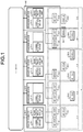
- FIG. 1 is a diagram illustrating a roadside information processing system according to an embodiment of the present invention.
- a roadside information processing system 100 includes sensors 10-1 to 10-8 and roadside devices 20-1 to 20-5.
- the sensors 10-1 to 10-8 are collectively referred to as "sensor 10" when the sensors 10-1 to 10-8 are described without being distinguished from each other.
- Each of the roadside devices 20-1 to 20-5 is collectively referred to as "roadside device 20" when the roadside devices 20-1 to 20-5 are described without being distinguished from each other.
- the sensor 10 and the roadside devices 20 are connected to each other through a network.
- the network connects to a central management device (not illustrated).
- the sensor 10 performs sensing to identify objects such as a vehicle 30, pedestrians, or obstructions around the sensor 10, and to monitor the road conditions, and transmits sensor information generated as results of the sensing to the roadside device 20.
- the roadside devices 20-1 to 20-5 include communication devices 21-1 to 21-5, respectively.
- Each of the communication devices 21-1 to 21-5 is collectively referred to as "communication device 21" when the communication devices 21-1 to 21-5 are described without being distinguished from each other.
- the communication device 21 communicates with vehicles 30-1 to 30-8 that are present in a communication available area.
- the communication available area for the communication device 21-1 is an area A-1.
- the communication available area for the communication device 21-2 is an area A-2.
- the communication available areas for the communication device 21-3, the communication device 21-4, and the communication device 21-5 are an area A-3, an area B-1, and an area B-2, respectively.
- the vehicle 30-1 is present in the area A-1.
- the vehicles 30-1 to 30-8 are collectively referred to as "vehicle 30" when the vehicles 30-1 to 30-8 are described without being distinguished from each other.
- the vehicle 30 includes an in-vehicle device having a communication function.
- the in-vehicle device includes an in-vehicle sensor, and uses the in-vehicle sensor to perform sensing in the same manner as the sensor 10 so as to generate in-vehicle sensor information.
- the sensor information and the in-vehicle sensor information are also referred to as "first information”.
- the communication device 21 collects the in-vehicle sensor information from the vehicle 30 that is present in the communication available area for the communication device 21. While the present embodiment describes eight sensors 10, the number of the sensors 10 is not limited to eight. While the present embodiment describes five roadside devices 20, the number of the roadside devices 20 is not limited to five.
- the roadside device 20-1 includes an edge-server processing unit 22-1.
- the roadside device 20-3 and the roadside device 20-5 include an edge-server processing unit 22-2 and an edge-server processing unit 22-3, respectively.
- Each of the edge-server processing units 22-1 to 22-3 is collectively referred to as "edge-server processing unit 22" when the edge-server processing units 22-1 to 22-3 are described without being distinguished from each other.
- At least one of the roadside devices 20 includes the edge-server processing unit 22.
- the edge-server processing unit 22 is implemented by application software additionally installed in a roadside device 20 already existing.
- the edge-server processing unit 22 is not always included in all the roadside devices 20, but is included in some selected roadside devices 20.
- the roadside device 20 in which the edge-server processing unit 22 is to be included is selected on the basis of the geographical positions of the areas A-1 to B-2, the shape of the road, the installation positions of the sensors 10, the number of the sensors 10 installed, and other conditions. Selection of which of the roadside devices 20 includes the edge-server processing unit 22 is described later in detail.
- the edge-server processing unit 22-1 collects in-vehicle sensor information collected by the communication devices 21-1 to 21-3, and sensor information generated by the sensors 10-1 to 10-5, and then processes, in real-time, these pieces of information into information on the position of the vehicle 30 in and around the area A, information on the movement direction of this vehicle 30, and information on the traffic jam conditions on the road.
- the information processed by the edge-server processing unit 22-1 is transmitted to the roadside devices 20-1 to 20-3, and transmitted to the vehicles 30-1 to 30-5 that are present in the areas A-1 to A-3 for the communication devices 21-1 to 21-3, respectively.
- the information processed by the edge-server processing unit 22-1 is also referred to as "second information".
- the edge-server processing unit 22-3 collects in-vehicle sensor information collected by the communication device 21-4 and the communication device 21-5, and sensor information generated by the sensors 10-6 to 10-8, and then processes, in real-time, these pieces of information into information on the position of the vehicle 30 in and around the area B, information on the movement direction of this vehicle 30, and information on the traffic jam conditions on the road.
- the processing to be performed by the edge-server processing unit 22 is general processing which is performed by, for example, Intersection Collision Risk Warning (ICRW) application or Longitudinal Collision Risk Warning (LCRW) application.
- ICRW Intersection Collision Risk Warning
- LCRW Longitudinal Collision Risk Warning
- the information processed by the edge-server processing unit 22-3 is transmitted to the roadside device 20-4 and the roadside device 20-5, and transmitted to the vehicles 30-6 to 30-8 that are present in the area B-1 and the area B-2 for the communication device 21-4 and the communication device 21-5, respectively.
- the edge-server processing unit 22-2 included in the roadside device 20-3 is in a standby state and thus does not operate.
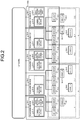
- FIG. 2 is a diagram illustrating another example of the roadside information processing system according to the embodiment.
- a roadside information processing system 100a is different in configuration from the roadside information processing system 100 in FIG. 1 in that a sensor 10-9 and a sensor 10-10 are added near the roadside device 20-3 and the roadside device 20-4.
- the communication available area for the communication device 21-3 included in the roadside device 20-3 is defined as an area B-3.
- An area combining the area B-1, the area B-2, and the area B-3 is defined as the area B which is enlarged relative to the area B in the roadside information processing system 100.
- the edge-server processing unit 22-2 performs processing in the area B.
- the area A is defined as an area only combining the area A-1 and the area A-2, and the edge-server processing unit 22-1 performs processing in the area A.
- the edge-server processing unit 22 is included is determined by, or which of the edge-server processing units 22 is activated is determined by, the number of the sensors 10 installed and the installation positions of the sensors 10.
- FIGS. 1 and 2 illustrate the configuration of the roadside information processing system, assuming that the sensors 10 are installed on the periphery of the road.
- the edge-server processing unit 22 deals with only in-vehicle sensor information from the vehicle 30, it is still possible to select the edge-server processing unit 22 to be installed or used, on the basis of the shape of the road and other conditions.
- the edge-server processing unit 22 is included is determined by the shape of the road in some cases. Examples of this determination include the case where the traveling area for the vehicle 30 becomes wider due to the increase in the number of lanes on the road and accordingly the edge-server processing unit 22 to be installed is determined in view of the wider area.
- FIG. 2 illustrates an example in which the number of the sensors 10 is increased. However, even in a case where the number of the roadside devices 20 is increased, it is still possible to select the edge-server processing unit 22 to be installed or used.
- FIG. 3 is a diagram illustrating the functional block of the edge-server processing unit 22 according to the embodiment.
- the edge-server processing unit 22 includes an edge processing unit 23 and an adaptation unit 24.
- the edge processing unit 23 connects to an in-vehicle device included in the vehicle 30 or connects to the sensor 10 to obtain in-vehicle sensor information or sensor information.
- the adaptation unit 24 assists the edge processing unit 23 in obtaining the in-vehicle sensor information and the sensor information.
- FIG. 4 is a diagram illustrating the functional block of the adaptation unit 24 according to the embodiment.
- the adaptation unit 24 includes a connection control unit 25, a connection proxy unit 26, a virtual area unit 27, and a storage unit 28.
- the connection control unit 25 determines a connection destination for the edge processing unit 23 and the type of the connection destination, and controls the order in which the edge processing unit 23 connects to the in-vehicle device or the sensor 10 to obtain in-vehicle sensor information and sensor information.
- the connection proxy unit 26 obtains sensor information from a virtual area.
- the connection proxy unit 26 transmits the sensor information to the edge processing unit 23.
- the virtual area unit 27 generates a virtual area in the storage unit 28 to save the sensor information obtained by the connection proxy unit 26.
- the storage unit 28 holds the virtual area in which the sensor information is saved.
- the edge processing unit 23 and the adaptation unit 24 according to the embodiment are implemented by processing circuitry that is electronic circuitry that performs each process.
- this processing circuitry is either dedicated hardware, or control circuitry including a memory and a CPU (Central Processing Unit) that executes a program stored in the memory.
- the memory described herein is a nonvolatile or volatile semiconductor memory such as a RAM (Random Access Memory), a ROM (Read Only Memory), or a flash memory, or is a magnetic disk or an optical disk.
- this processing circuitry is control circuitry including the CPU, this control circuitry is, for example, control circuitry 200 that is configured as illustrated in FIG. 5 .
- the control circuitry 200 includes a processor 200a that is the CPU, and a memory 200b.
- the processor 200a reads and executes a program that is stored in the memory 200b and that corresponds to each process, thereby implementing the processing circuitry.
- the memory 200b is also used as a temporary memory for the processor 200a to perform each process.
- FIG. 6 is a flowchart illustrating operation of the edge processing unit 23 and the adaptation unit 24 according to the embodiment.
- FIG. 6 illustrates the case where the edge processing unit 23 obtains sensor information from the sensor 10. Only a small number of the sensors 10 include a memory in themselves, and most of the sensors 10 transmit sensor information indicating data sensed by the sensors 10 without saving the sensor information. For this reason, the sensor information is held in the storage unit 28 included in the adaptation unit 24, and is processed virtually as if the edge processing unit 23 has obtained the sensor information from the sensor 10.
- the edge processing unit 23 initializes "j" that indicates the value of a device ID (Identification) to 0 (Step S1).
- the device ID is a value uniquely assigned to a device such as the sensor 10 and an in-vehicle device from which the edge processing unit 23 obtains the first information.
- the sensor 10-1 is assigned with 1 as the device ID
- the sensor 10-2 is assigned with 2 as the device ID.
- the edge processing unit 23 increments the value of "j" by 1 (Step S2).
- the edge processing unit 23 obtains the first information from a device in accordance with the value of "j".
- the connection control unit 25 determines a connection destination for the edge processing unit 23.
- connection control unit 25 determines that the connection destination is a device that cannot hold therein sensor information such as the sensor 10
- the connection control unit 25 notifies the connection proxy unit 26 of information indicating that the connection destination is a device that cannot hold therein sensor information, and causes the connection proxy unit 26 to obtain sensor information from the virtual area (Step S3).
- the determination method for the connection control unit 25 regarding whether the device can hold therein data information on whether the device can save therein data is held in the storage unit 28 for each device ID, and the connection control unit 25 refers to this information and thereby performs the determination.
- the connection proxy unit 26 obtains the sensor information generated by the sensor 10 from the virtual area generated in the storage unit 28, and transmits the sensor information generated by the sensor 10 to the edge processing unit 23 via the connection control unit 25 (Step S4). At this time, the connection proxy unit 26 transmits the sensor information to the edge processing unit 23, so that even when the edge processing unit 23 accesses a device that does not hold a storage area, such as the sensor 10, the edge processing unit 23 can still receive the sensor information from the connection proxy unit 26, and can thus operate in the same manner as the case where the sensor 10 holds a storage area.
- the edge processing unit 23 performs real-time processing by using the received sensor information (Step S5). When the value of the device ID is not the maximum value (NO at Step S6), the processing returns to Step S2.
- the maximum value of the device ID is a maximum value of the number of devices to be handled by the edge processing unit 23. It is allowable that the edge processing unit 23 performs real-time processing at a timing after the edge processing unit 23 has completely received the first information from all the devices.
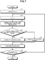
- FIG. 7 is another flowchart illustrating operation of the edge processing unit 23 and the adaptation unit 24 according to the embodiment.
- FIG. 7 includes a process of obtaining the first information from an external device holding a storage area, such as an in-vehicle device.
- Steps S7 and S8 are added to FIG. 7 .
- Steps S1 to S6 are the same as those in FIG. 6 .
- Step S3 when the connection destination for the edge processing unit 23 is an external device holding a storage area, such as an in-vehicle device (YES at Step S7), the connection control unit 25 does not change the connection destination for the edge processing unit 23, and then the edge processing unit 23 connects to the external device that is the in-vehicle device to obtain in-vehicle sensor information (Step S8).
- the processing advances to Step S4.
- edge-server processing unit 22 it is possible to implement the edge-server processing unit 22 in accordance with the shape of the road or the installation conditions of a device such as the sensor 10. All the roadside devices 20 do not necessarily include the edge-server processing unit 22. Because the edge-server processing unit 22 is implemented by being additionally installed in the existing roadside device, the existing roadside device can still be used. This makes it possible to perform real-time processing and distribute information at minimum cost.
- a standby edge-server processing unit 22 may be implemented in advance in accordance with plans for the future addition or deletion of facilities such as the sensors 10, or in accordance with road reconstruction, so that it is possible to flexibly accommodate the system change.
- the edge-server processing unit 22 includes the edge processing unit 23 and the adaptation unit 24, and the adaptation unit 24 includes a virtual area in the storage unit 28 for holding sensor information generated by the sensor 10. Due to this configuration, the edge processing unit 23 can obtain information from a device that does not hold a storage area. Further, an information distribution system related to driving assistance can be constructed by using the existing facilities or application, such as the roadside device 20 and the existing application already installed in the roadside device 20, as well as ITS-related devices or the network that connects these ITS-related devices. This can therefore reduce capital investment.
- 10, 10-1 to 10-10 sensor 20, 20-1 to 20-5 roadside device, 21, 21-1 to 21-5 communication device, 22, 22-1 to 22-3 edge-server processing unit, 23 edge processing unit, 24 adaptation unit, 25 connection control unit, 26 connection proxy unit, 27 virtual area unit, 28 storage unit, 30, 30-1 to 30-8 vehicle, 100, 100a roadside information processing system, 200 control circuitry, 200a processor, 200b memory.
Landscapes
- Physics & Mathematics (AREA)
- General Physics & Mathematics (AREA)
- Engineering & Computer Science (AREA)
- Analytical Chemistry (AREA)
- Chemical & Material Sciences (AREA)
- Automation & Control Theory (AREA)
- Mathematical Physics (AREA)
- Transportation (AREA)
- Mechanical Engineering (AREA)
- Computer Networks & Wireless Communication (AREA)
- Signal Processing (AREA)
- Life Sciences & Earth Sciences (AREA)
- Atmospheric Sciences (AREA)
- Traffic Control Systems (AREA)
Abstract
Description
- The present invention relates to a roadside information processing system that uses information obtained from a sensor or an in-vehicle device to generate information to be used by a vehicle.
- In recent years, in the field of transportation means such as automobiles and railways, research and development of driving assistance such as assistance for automated driving and assistance for safe driving have been actively performed. In order to provide the driving assistance described above, driving assistance information is needed such as identification results of objects including vehicles, pedestrians, or obstructions. The driving assistance information is generated by a vehicle and a roadside device. The vehicle and the roadside device have a device mounted thereon to obtain surrounding information, such as a sensor or camera. The vehicle and the roadside device generate driving assistance information on the basis of the surrounding information obtained by the sensor or camera. The surrounding information obtained by these devices, and the driving assistance information generated by the vehicle and the roadside device on the basis of the surrounding information are required to be obtained in real-time. These kinds of information are required to be information corresponding to the shape of the road, the traffic volume, or a change in the area where the vehicle is located. The shape of the road described herein indicates that the road is either straight or curved, or that the road is either a basic road section or at an intersection, or indicates the number of lanes on the road, indicates that the lanes are either wide or narrow, or indicates other conditions. It is desired to efficiently construct a roadside information processing system that satisfies these requirements. Roadside devices in ITS (Intelligent Transport Systems) have already been set up on the roadside. Each of the roadside devices is equipped with a communication device and other devices, and is used for distributing road traffic information or for electronic road pricing. It is efficient that a roadside information processing system that satisfies the requirements described above can be constructed by utilizing the systems having already been set up.
-
Patent Literature 1 discloses a roadside information processing system including a visible-light sensor included in a vehicle to capture an image pattern painted on a road in order that the vehicle communicates with a roadside device to perform handover processing at a proper timing, and a wireless communication device that determines that a cell corresponding to the image pattern is a handover destination cell. The cell refers to a communication range of a wireless base station in mobile communication. - Patent Literature 1: Japanese Patent Application Laid-open No.
2003-319429 - However, the roadside information processing system described in
Patent Literature 1 cannot use the existing roadside devices, and instead roadside devices need to be newly provided. It is thus difficult to efficiently construct the roadside information processing system. - The present invention has been made in view of the above problems, and an object of the present invention is to provide a roadside information processing system in which the existing roadside devices can still be used.
- To solve the above problem and achieve an object, there is provided a roadside information processing system according to the present invention including: a plurality of roadside devices installed on a roadside of a road and capable of communicating with a vehicle travelling on the road; and a plurality of sensors installed on the roadside to perform sensing on the road and a periphery thereof, wherein at least one of the roadside devices includes an edge-server processing unit to obtain first information from an in-vehicle device included in the vehicle and from some of the plurality of the sensors, the first information indicating information about a periphery of the vehicle and about the road and a periphery thereof, and to generate second information by using the first information, the second information indicating a position of the vehicle, a movement direction of the vehicle, and traffic jam conditions on the road.
- The roadside information processing system according to the present invention has an effect where the existing roadside devices can still be used.
-
-
FIG. 1 is a diagram illustrating a roadside information processing system according to an embodiment. -
FIG. 2 is a diagram illustrating another example of the roadside information processing system according to the embodiment. -
FIG. 3 is a diagram illustrating a functional block of an edge-server processing unit according to the embodiment. -
FIG. 4 is a diagram illustrating a functional block of an adaptation unit according to the embodiment. -
FIG. 5 is diagram illustrating control circuitry according to the embodiment. -
FIG. 6 is a flowchart illustrating operation of an edge processing unit and the adaptation unit according to the embodiment. -
FIG. 7 is another flowchart illustrating operation of the edge processing unit and the adaptation unit according to the embodiment. - A roadside information processing system according to an embodiment of the present invention will be described in detail below with reference to the accompanying drawings. The present invention is not limited to the embodiment.
-
FIG. 1 is a diagram illustrating a roadside information processing system according to an embodiment of the present invention. A roadsideinformation processing system 100 includes sensors 10-1 to 10-8 and roadside devices 20-1 to 20-5. The sensors 10-1 to 10-8 are collectively referred to as "sensor 10" when the sensors 10-1 to 10-8 are described without being distinguished from each other. Each of the roadside devices 20-1 to 20-5 is collectively referred to as "roadside device 20" when the roadside devices 20-1 to 20-5 are described without being distinguished from each other. The sensor 10 and the roadside devices 20 are connected to each other through a network. The network connects to a central management device (not illustrated). The sensor 10 performs sensing to identify objects such as a vehicle 30, pedestrians, or obstructions around the sensor 10, and to monitor the road conditions, and transmits sensor information generated as results of the sensing to the roadside device 20. - The roadside devices 20-1 to 20-5 include communication devices 21-1 to 21-5, respectively. Each of the communication devices 21-1 to 21-5 is collectively referred to as "communication device 21" when the communication devices 21-1 to 21-5 are described without being distinguished from each other. The communication device 21 communicates with vehicles 30-1 to 30-8 that are present in a communication available area. The communication available area for the communication device 21-1 is an area A-1. The communication available area for the communication device 21-2 is an area A-2. Similarly, the communication available areas for the communication device 21-3, the communication device 21-4, and the communication device 21-5 are an area A-3, an area B-1, and an area B-2, respectively. For example, the vehicle 30-1 is present in the area A-1. An area combining the area A-1, the area A-2, and the area A-3 is referred to as "area A". An area combining the area B-1 and the area B-2 is referred to as "area B". The vehicles 30-1 to 30-8 are collectively referred to as "vehicle 30" when the vehicles 30-1 to 30-8 are described without being distinguished from each other. The vehicle 30 includes an in-vehicle device having a communication function. The in-vehicle device includes an in-vehicle sensor, and uses the in-vehicle sensor to perform sensing in the same manner as the sensor 10 so as to generate in-vehicle sensor information. The sensor information and the in-vehicle sensor information are also referred to as "first information". The communication device 21 collects the in-vehicle sensor information from the vehicle 30 that is present in the communication available area for the communication device 21. While the present embodiment describes eight sensors 10, the number of the sensors 10 is not limited to eight. While the present embodiment describes five roadside devices 20, the number of the roadside devices 20 is not limited to five.
- The roadside device 20-1 includes an edge-server processing unit 22-1. Similarly, the roadside device 20-3 and the roadside device 20-5 include an edge-server processing unit 22-2 and an edge-server processing unit 22-3, respectively. Each of the edge-server processing units 22-1 to 22-3 is collectively referred to as "edge-
server processing unit 22" when the edge-server processing units 22-1 to 22-3 are described without being distinguished from each other. At least one of the roadside devices 20 includes the edge-server processing unit 22. The edge-server processing unit 22 is implemented by application software additionally installed in a roadside device 20 already existing. The edge-server processing unit 22 is not always included in all the roadside devices 20, but is included in some selected roadside devices 20. The roadside device 20 in which the edge-server processing unit 22 is to be included is selected on the basis of the geographical positions of the areas A-1 to B-2, the shape of the road, the installation positions of the sensors 10, the number of the sensors 10 installed, and other conditions. Selection of which of the roadside devices 20 includes the edge-server processing unit 22 is described later in detail. - The edge-server processing unit 22-1 collects in-vehicle sensor information collected by the communication devices 21-1 to 21-3, and sensor information generated by the sensors 10-1 to 10-5, and then processes, in real-time, these pieces of information into information on the position of the vehicle 30 in and around the area A, information on the movement direction of this vehicle 30, and information on the traffic jam conditions on the road. The information processed by the edge-server processing unit 22-1 is transmitted to the roadside devices 20-1 to 20-3, and transmitted to the vehicles 30-1 to 30-5 that are present in the areas A-1 to A-3 for the communication devices 21-1 to 21-3, respectively. The information processed by the edge-server processing unit 22-1 is also referred to as "second information". Similarly, the edge-server processing unit 22-3 collects in-vehicle sensor information collected by the communication device 21-4 and the communication device 21-5, and sensor information generated by the sensors 10-6 to 10-8, and then processes, in real-time, these pieces of information into information on the position of the vehicle 30 in and around the area B, information on the movement direction of this vehicle 30, and information on the traffic jam conditions on the road. The processing to be performed by the edge-
server processing unit 22 is general processing which is performed by, for example, Intersection Collision Risk Warning (ICRW) application or Longitudinal Collision Risk Warning (LCRW) application. The information processed by the edge-server processing unit 22-3 is transmitted to the roadside device 20-4 and the roadside device 20-5, and transmitted to the vehicles 30-6 to 30-8 that are present in the area B-1 and the area B-2 for the communication device 21-4 and the communication device 21-5, respectively. InFIG. 1 , the edge-server processing unit 22-2 included in the roadside device 20-3 is in a standby state and thus does not operate. -
FIG. 2 is a diagram illustrating another example of the roadside information processing system according to the embodiment. A roadsideinformation processing system 100a is different in configuration from the roadsideinformation processing system 100 inFIG. 1 in that a sensor 10-9 and a sensor 10-10 are added near the roadside device 20-3 and the roadside device 20-4. In the roadsideinformation processing system 100a, the communication available area for the communication device 21-3 included in the roadside device 20-3 is defined as an area B-3. An area combining the area B-1, the area B-2, and the area B-3 is defined as the area B which is enlarged relative to the area B in the roadsideinformation processing system 100. The edge-server processing unit 22-2 performs processing in the area B. In association with the enlargement of the area B, the area A is defined as an area only combining the area A-1 and the area A-2, and the edge-server processing unit 22-1 performs processing in the area A. As described above, in which of the roadside devices 20 the edge-server processing unit 22 is included is determined by, or which of the edge-server processing units 22 is activated is determined by, the number of the sensors 10 installed and the installation positions of the sensors 10.FIGS. 1 and2 illustrate the configuration of the roadside information processing system, assuming that the sensors 10 are installed on the periphery of the road. However, even in a case where the sensors 10 are not installed and the edge-server processing unit 22 deals with only in-vehicle sensor information from the vehicle 30, it is still possible to select the edge-server processing unit 22 to be installed or used, on the basis of the shape of the road and other conditions. In which of the roadside devices 20 the edge-server processing unit 22 is included is determined by the shape of the road in some cases. Examples of this determination include the case where the traveling area for the vehicle 30 becomes wider due to the increase in the number of lanes on the road and accordingly the edge-server processing unit 22 to be installed is determined in view of the wider area.FIG. 2 illustrates an example in which the number of the sensors 10 is increased. However, even in a case where the number of the roadside devices 20 is increased, it is still possible to select the edge-server processing unit 22 to be installed or used. -
FIG. 3 is a diagram illustrating the functional block of the edge-server processing unit 22 according to the embodiment. The edge-server processing unit 22 includes an edge processing unit 23 and an adaptation unit 24. The edge processing unit 23 connects to an in-vehicle device included in the vehicle 30 or connects to the sensor 10 to obtain in-vehicle sensor information or sensor information. The adaptation unit 24 assists the edge processing unit 23 in obtaining the in-vehicle sensor information and the sensor information. -
FIG. 4 is a diagram illustrating the functional block of the adaptation unit 24 according to the embodiment. The adaptation unit 24 includes aconnection control unit 25, a connection proxy unit 26, a virtual area unit 27, and a storage unit 28. Theconnection control unit 25 determines a connection destination for the edge processing unit 23 and the type of the connection destination, and controls the order in which the edge processing unit 23 connects to the in-vehicle device or the sensor 10 to obtain in-vehicle sensor information and sensor information. When theconnection control unit 25 determines that the connection destination for the edge processing unit 23 is the sensor 10, the connection proxy unit 26 obtains sensor information from a virtual area. The connection proxy unit 26 transmits the sensor information to the edge processing unit 23. The virtual area unit 27 generates a virtual area in the storage unit 28 to save the sensor information obtained by the connection proxy unit 26. The storage unit 28 holds the virtual area in which the sensor information is saved. - The edge processing unit 23 and the adaptation unit 24 according to the embodiment are implemented by processing circuitry that is electronic circuitry that performs each process.
- It is allowable that this processing circuitry is either dedicated hardware, or control circuitry including a memory and a CPU (Central Processing Unit) that executes a program stored in the memory. For example, the memory described herein is a nonvolatile or volatile semiconductor memory such as a RAM (Random Access Memory), a ROM (Read Only Memory), or a flash memory, or is a magnetic disk or an optical disk. In a case where this processing circuitry is control circuitry including the CPU, this control circuitry is, for example,
control circuitry 200 that is configured as illustrated inFIG. 5 . - As illustrated in
FIG. 5 , thecontrol circuitry 200 includes aprocessor 200a that is the CPU, and amemory 200b. In a case where the processing circuitry is implemented by thecontrol circuitry 200 illustrated inFIG. 5 , theprocessor 200a reads and executes a program that is stored in thememory 200b and that corresponds to each process, thereby implementing the processing circuitry. Thememory 200b is also used as a temporary memory for theprocessor 200a to perform each process. -
FIG. 6 is a flowchart illustrating operation of the edge processing unit 23 and the adaptation unit 24 according to the embodiment.FIG. 6 illustrates the case where the edge processing unit 23 obtains sensor information from the sensor 10. Only a small number of the sensors 10 include a memory in themselves, and most of the sensors 10 transmit sensor information indicating data sensed by the sensors 10 without saving the sensor information. For this reason, the sensor information is held in the storage unit 28 included in the adaptation unit 24, and is processed virtually as if the edge processing unit 23 has obtained the sensor information from the sensor 10. - The edge processing unit 23 initializes "j" that indicates the value of a device ID (Identification) to 0 (Step S1). The device ID is a value uniquely assigned to a device such as the sensor 10 and an in-vehicle device from which the edge processing unit 23 obtains the first information. For example, the sensor 10-1 is assigned with 1 as the device ID, and the sensor 10-2 is assigned with 2 as the device ID. The edge processing unit 23 increments the value of "j" by 1 (Step S2). The edge processing unit 23 obtains the first information from a device in accordance with the value of "j". At this time, the
connection control unit 25 determines a connection destination for the edge processing unit 23. When theconnection control unit 25 determines that the connection destination is a device that cannot hold therein sensor information such as the sensor 10, theconnection control unit 25 notifies the connection proxy unit 26 of information indicating that the connection destination is a device that cannot hold therein sensor information, and causes the connection proxy unit 26 to obtain sensor information from the virtual area (Step S3). As an example of the determination method for theconnection control unit 25 regarding whether the device can hold therein data, information on whether the device can save therein data is held in the storage unit 28 for each device ID, and theconnection control unit 25 refers to this information and thereby performs the determination. - The connection proxy unit 26 obtains the sensor information generated by the sensor 10 from the virtual area generated in the storage unit 28, and transmits the sensor information generated by the sensor 10 to the edge processing unit 23 via the connection control unit 25 (Step S4). At this time, the connection proxy unit 26 transmits the sensor information to the edge processing unit 23, so that even when the edge processing unit 23 accesses a device that does not hold a storage area, such as the sensor 10, the edge processing unit 23 can still receive the sensor information from the connection proxy unit 26, and can thus operate in the same manner as the case where the sensor 10 holds a storage area. The edge processing unit 23 performs real-time processing by using the received sensor information (Step S5). When the value of the device ID is not the maximum value (NO at Step S6), the processing returns to Step S2. When the value of the device ID is the maximum value (YES at Step S6), the processing ends. The maximum value of the device ID is a maximum value of the number of devices to be handled by the edge processing unit 23. It is allowable that the edge processing unit 23 performs real-time processing at a timing after the edge processing unit 23 has completely received the first information from all the devices.
-
FIG. 7 is another flowchart illustrating operation of the edge processing unit 23 and the adaptation unit 24 according to the embodiment.FIG. 7 includes a process of obtaining the first information from an external device holding a storage area, such as an in-vehicle device. As compared toFIG. 6 , Steps S7 and S8 are added toFIG. 7 . Steps S1 to S6 are the same as those inFIG. 6 . After Step S3, when the connection destination for the edge processing unit 23 is an external device holding a storage area, such as an in-vehicle device (YES at Step S7), theconnection control unit 25 does not change the connection destination for the edge processing unit 23, and then the edge processing unit 23 connects to the external device that is the in-vehicle device to obtain in-vehicle sensor information (Step S8). When the obtaining destination is not an external device holding a storage area, such as an in-vehicle device (NO at Step S7), the processing advances to Step S4. - As explained above, in the present embodiment, it is possible to implement the edge-
server processing unit 22 in accordance with the shape of the road or the installation conditions of a device such as the sensor 10. All the roadside devices 20 do not necessarily include the edge-server processing unit 22. Because the edge-server processing unit 22 is implemented by being additionally installed in the existing roadside device, the existing roadside device can still be used. This makes it possible to perform real-time processing and distribute information at minimum cost. A standby edge-server processing unit 22 may be implemented in advance in accordance with plans for the future addition or deletion of facilities such as the sensors 10, or in accordance with road reconstruction, so that it is possible to flexibly accommodate the system change. - The edge-
server processing unit 22 includes the edge processing unit 23 and the adaptation unit 24, and the adaptation unit 24 includes a virtual area in the storage unit 28 for holding sensor information generated by the sensor 10. Due to this configuration, the edge processing unit 23 can obtain information from a device that does not hold a storage area. Further, an information distribution system related to driving assistance can be constructed by using the existing facilities or application, such as the roadside device 20 and the existing application already installed in the roadside device 20, as well as ITS-related devices or the network that connects these ITS-related devices. This can therefore reduce capital investment. - The configurations described in the above embodiment are only examples of the content of the present invention. The configurations can be combined with other well-known techniques, and part of each of the configurations can be omitted or modified without departing from the scope of the present invention.
- 10, 10-1 to 10-10 sensor, 20, 20-1 to 20-5 roadside device, 21, 21-1 to 21-5 communication device, 22, 22-1 to 22-3 edge-server processing unit, 23 edge processing unit, 24 adaptation unit, 25 connection control unit, 26 connection proxy unit, 27 virtual area unit, 28 storage unit, 30, 30-1 to 30-8 vehicle, 100, 100a roadside information processing system, 200 control circuitry, 200a processor, 200b memory.
Claims (7)
- A roadside information processing system comprising:a plurality of roadside devices installed on a roadside of a road and capable of communicating with a vehicle travelling on the road; anda plurality of sensors installed on the roadside to perform sensing on the road and a periphery thereof, whereinat least one of the roadside devices includes an edge-server processing unit to obtain first information from an in-vehicle device included in the vehicle and from some of the plurality of the sensors, the first information indicating information about a periphery of the vehicle and about the road and a periphery thereof, and to generate second information by using the first information, the second information indicating a position of the vehicle, a movement direction of the vehicle, and traffic jam conditions on the road.
- The roadside information processing system according to claim 1, wherein the edge-server processing unit is implemented by application software additionally installed in the at least one of the roadside devices already existing.
- The roadside information processing system according to claim 1 or 2, wherein the at least one of the roadside devices which includes the edge-server processing unit, is selected from among the plurality of the roadside devices on a basis of a shape of the road, positions of the sensors, and positions of the roadside devices.
- The roadside information processing system according to any one of claims 1 to 3, wherein from which of the plurality of the roadside devices and from which of the plurality of the sensors the edge-server processing unit obtains the first information, are determined by a shape of the road, positions of the roadside devices, and positions of the sensors.
- The roadside information processing system according to any one of claims 1 to 4, wherein whether the edge-server processing unit is activated is determined by a shape of the road, positions of the sensors, and positions of the roadside devices.
- The roadside information processing system according to any one of claims 1 to 5, wherein
the edge-server processing unit includes
an edge processing unit to connect to some of the plurality of the roadside devices or some of the plurality of the sensors,
a connection control unit to determine a connection destination for the edge processing unit,
a virtual area unit to generate a virtual area for holding sensor information indicating information sensed and generated by the some of the sensors, and
a connection proxy unit to obtain the sensor information from the virtual area when the connection control unit determines that a connection destination for the edge processing unit is one of the some of the sensors, and to transmit the sensor information to the edge processing unit, and
the first information includes the sensor information. - The roadside information processing system according to claim 6, wherein
when the connection control unit determines that a connection destination for the edge processing unit is the in-vehicle device, the connection control unit causes the edge processing unit to obtain in-vehicle sensor information from the in-vehicle device, the in-vehicle sensor information being information sensed and generated by an in-vehicle sensor included in the vehicle, and
the first information includes the in-vehicle sensor information.
Applications Claiming Priority (1)
| Application Number | Priority Date | Filing Date | Title |
|---|---|---|---|
| PCT/JP2018/021752 WO2019234863A1 (en) | 2018-06-06 | 2018-06-06 | Roadside information processing system |
Publications (3)
| Publication Number | Publication Date |
|---|---|
| EP3789982A1 true EP3789982A1 (en) | 2021-03-10 |
| EP3789982A4 EP3789982A4 (en) | 2021-06-23 |
| EP3789982B1 EP3789982B1 (en) | 2024-04-10 |
Family
ID=66934391
Family Applications (1)
| Application Number | Title | Priority Date | Filing Date |
|---|---|---|---|
| EP18921448.9A Active EP3789982B1 (en) | 2018-06-06 | 2018-06-06 | Roadside information processing system |
Country Status (5)
| Country | Link |
|---|---|
| US (1) | US12008894B2 (en) |
| EP (1) | EP3789982B1 (en) |
| JP (1) | JP6532617B1 (en) |
| CN (1) | CN112204632B (en) |
| WO (1) | WO2019234863A1 (en) |
Families Citing this family (3)
| Publication number | Priority date | Publication date | Assignee | Title |
|---|---|---|---|---|
| CN112560724B (en) * | 2020-12-22 | 2023-12-05 | 阿波罗智联(北京)科技有限公司 | Vehicle monitoring method and device and cloud control platform |
| CN113450569A (en) * | 2021-06-30 | 2021-09-28 | 阿波罗智联(北京)科技有限公司 | Method, device, electronic equipment and storage medium for determining intersection state |
| US12101578B2 (en) | 2021-10-04 | 2024-09-24 | Toyota Motor Engineering & Manufacturing North America, Inc. | Context-aware large scale surrounding view with RSU assist |
Family Cites Families (32)
| Publication number | Priority date | Publication date | Assignee | Title |
|---|---|---|---|---|
| DE19903909A1 (en) * | 1999-02-01 | 2000-08-03 | Delphi 2 Creative Tech Gmbh | Method and device for obtaining relevant traffic information and for dynamic route optimization |
| JP2003319429A (en) | 2002-04-19 | 2003-11-07 | Matsushita Electric Ind Co Ltd | Wireless communication device and road-vehicle communication system |
| US20060206610A1 (en) | 2005-03-09 | 2006-09-14 | Yibei Ling | Method, system and apparatus for location-aware content push service and location-based dynamic attachment |
| US9384659B2 (en) * | 2009-11-10 | 2016-07-05 | Mitsubishi Electric Corporation | Driving support system |
| JP5578032B2 (en) * | 2010-11-01 | 2014-08-27 | 株式会社デンソー | Communication device |
| JP5825138B2 (en) * | 2011-09-10 | 2015-12-02 | 株式会社デンソー | Prior vehicle follow-up travel device and driving support system |
| JP6340891B2 (en) * | 2014-04-22 | 2018-06-13 | 株式会社デンソー | In-vehicle communication terminal and mobile communication system |
| JP6361618B2 (en) * | 2015-09-15 | 2018-07-25 | トヨタ自動車株式会社 | Driving assistance device |
| JP6812979B2 (en) * | 2015-09-18 | 2021-01-13 | 日本電気株式会社 | RSU devices, control nodes, and methods thereof |
| US9922553B2 (en) * | 2015-12-22 | 2018-03-20 | Intel Corporation | Vehicle assistance systems and methods utilizing vehicle to vehicle communications |
| US10148790B2 (en) * | 2016-03-04 | 2018-12-04 | Bank Of America Corporation | Deployment of integrative HTML-based engine from an edge server |
| WO2017202461A1 (en) * | 2016-05-25 | 2017-11-30 | Siemens Aktiengesellschaft | Method, device and arrangement for tracking moving objects |
| US9965950B2 (en) * | 2016-06-03 | 2018-05-08 | Here Global B.V. | Method and apparatus for classifying a traffic jam from probe data |
| US10347122B2 (en) * | 2016-07-12 | 2019-07-09 | Denson Corporation | Road condition monitoring system |
| JP6888253B2 (en) | 2016-07-27 | 2021-06-16 | 住友電気工業株式会社 | A method for determining whether or not to adopt a wireless communication system, an information acquisition terminal, a computer program, and provided information |
| JP6697349B2 (en) * | 2016-08-10 | 2020-05-20 | パナソニック インテレクチュアル プロパティ コーポレーション オブ アメリカPanasonic Intellectual Property Corporation of America | Communication method and server |
| CN106412048B (en) * | 2016-09-26 | 2020-01-21 | 北京东土科技股份有限公司 | Information processing method and device based on intelligent traffic cloud control system |
| US10539966B2 (en) * | 2016-09-28 | 2020-01-21 | Denso Corporation | Service cooperation system for vehicle |
| JP2018081504A (en) * | 2016-11-16 | 2018-05-24 | 富士通株式会社 | Traffic control device, traffic control method, and traffic control program |
| US10380886B2 (en) * | 2017-05-17 | 2019-08-13 | Cavh Llc | Connected automated vehicle highway systems and methods |
| JP6872959B2 (en) * | 2017-04-20 | 2021-05-19 | パナソニック インテレクチュアル プロパティ コーポレーション オブ アメリカPanasonic Intellectual Property Corporation of America | Communication systems, vehicle mounts and programs |
| JP6826940B2 (en) * | 2017-04-26 | 2021-02-10 | 京セラ株式会社 | Electronics, roadside units, operating methods and control programs and transportation systems |
| US10692365B2 (en) * | 2017-06-20 | 2020-06-23 | Cavh Llc | Intelligent road infrastructure system (IRIS): systems and methods |
| US12020563B2 (en) * | 2017-05-17 | 2024-06-25 | Cavh Llc | Autonomous vehicle and cloud control system |
| US10210617B2 (en) * | 2017-05-26 | 2019-02-19 | Dura Operating, Llc | Method and system for generating a perception scene graph having a focus region for a motor vehicle |
| US20180341821A1 (en) * | 2017-05-26 | 2018-11-29 | Dura Operating, Llc | Method and system for generating and using a perception scene graph in motor vehicle applications |
| US20190208449A1 (en) * | 2017-12-29 | 2019-07-04 | Industrial Technology Research Institute | Mobile edge platform servers and device and message management methods of v2x service thereof |
| WO2019156956A2 (en) * | 2018-02-06 | 2019-08-15 | Cavh Llc | Intelligent road infrastructure system (iris): systems and methods |
| WO2019199815A1 (en) * | 2018-04-10 | 2019-10-17 | Cavh Llc | Connected and automated vehicle systems and methods for the entire roadway network |
| US11153721B2 (en) * | 2018-12-27 | 2021-10-19 | Intel Corporation | Sensor network enhancement mechanisms |
| US12002361B2 (en) * | 2019-07-03 | 2024-06-04 | Cavh Llc | Localized artificial intelligence for intelligent road infrastructure |
| CN112712719B (en) * | 2020-12-25 | 2022-05-03 | 阿波罗智联(北京)科技有限公司 | Vehicle control method, vehicle-road coordination system, road side equipment and automatic driving vehicle |
-
2018
- 2018-06-06 CN CN201880094058.3A patent/CN112204632B/en active Active
- 2018-06-06 EP EP18921448.9A patent/EP3789982B1/en active Active
- 2018-06-06 JP JP2018555790A patent/JP6532617B1/en active Active
- 2018-06-06 WO PCT/JP2018/021752 patent/WO2019234863A1/en not_active Ceased
-
2020
- 2020-10-29 US US17/083,555 patent/US12008894B2/en active Active
Also Published As
| Publication number | Publication date |
|---|---|
| EP3789982B1 (en) | 2024-04-10 |
| WO2019234863A1 (en) | 2019-12-12 |
| JPWO2019234863A1 (en) | 2020-06-18 |
| US20210074148A1 (en) | 2021-03-11 |
| CN112204632B (en) | 2022-06-14 |
| US12008894B2 (en) | 2024-06-11 |
| EP3789982A4 (en) | 2021-06-23 |
| JP6532617B1 (en) | 2019-06-19 |
| CN112204632A (en) | 2021-01-08 |
Similar Documents
| Publication | Publication Date | Title |
|---|---|---|
| US12518622B2 (en) | Autonomous vehicle intelligent driving system with weather and special information | |
| US11087621B2 (en) | Express lane planning method and unit | |
| US11731627B2 (en) | Road anomaly detection for autonomous vehicle | |
| US10917808B2 (en) | Extra-vehicular communication device, onboard device, onboard communication system, communication control method, and communication control program | |
| US12008894B2 (en) | Roadside information processing system | |
| CN109410633A (en) | A kind of intelligent garage parking stall navigation methods and systems | |
| US20220410900A1 (en) | Assertive vehicle detection model generation | |
| KR102011598B1 (en) | Emergency traffic control system using mobile device | |
| CN105427658A (en) | Parking lot management method and parking lot management system based on iBeacon intelligent route guidance terminal | |
| CN105407170A (en) | Internet of vehicles system with link protection | |
| US10953871B2 (en) | Transportation infrastructure communication and control | |
| JP2020091652A (en) | Information providing system, server, and computer program | |
| JP6960956B2 (en) | On-board unit, road-to-vehicle communication system using it, and roadside unit information notification method | |
| US20250347528A1 (en) | Method for finding a charging station for electric motor vehicles | |
| KR101391324B1 (en) | Method for recognizing traffic condition based on event rule using data detected by a radar and apparatus thereof | |
| JP2025104900A (en) | Information processing device | |
| CN116246454A (en) | Vehicle control method, decision server and storage medium | |
| RU2783351C2 (en) | Vehicle control device and wireless communication network | |
| CN220823299U (en) | Tunnel scene vehicle position detection system based on ETC | |
| JP4141469B2 (en) | DSRC OBE | |
| US20260127960A1 (en) | Autonomous vehicle control system with data fusion | |
| JP6769381B2 (en) | Vehicle data collection system | |
| CZ306395B6 (en) | Communication device for means of conveyance | |
| JPS6159600A (en) | Vehicle operation managing system |
Legal Events
| Date | Code | Title | Description |
|---|---|---|---|
| STAA | Information on the status of an ep patent application or granted ep patent |
Free format text: STATUS: THE INTERNATIONAL PUBLICATION HAS BEEN MADE |
|
| PUAI | Public reference made under article 153(3) epc to a published international application that has entered the european phase |
Free format text: ORIGINAL CODE: 0009012 |
|
| STAA | Information on the status of an ep patent application or granted ep patent |
Free format text: STATUS: REQUEST FOR EXAMINATION WAS MADE |
|
| 17P | Request for examination filed |
Effective date: 20201117 |
|
| AK | Designated contracting states |
Kind code of ref document: A1 Designated state(s): AL AT BE BG CH CY CZ DE DK EE ES FI FR GB GR HR HU IE IS IT LI LT LU LV MC MK MT NL NO PL PT RO RS SE SI SK SM TR |
|
| AX | Request for extension of the european patent |
Extension state: BA ME |
|
| A4 | Supplementary search report drawn up and despatched |
Effective date: 20210526 |
|
| RIC1 | Information provided on ipc code assigned before grant |
Ipc: G08G 1/01 20060101AFI20210519BHEP Ipc: G08G 1/09 20060101ALI20210519BHEP Ipc: G08G 1/056 20060101ALI20210519BHEP Ipc: G08G 1/0967 20060101ALI20210519BHEP |
|
| DAV | Request for validation of the european patent (deleted) | ||
| DAX | Request for extension of the european patent (deleted) | ||
| GRAP | Despatch of communication of intention to grant a patent |
Free format text: ORIGINAL CODE: EPIDOSNIGR1 |
|
| STAA | Information on the status of an ep patent application or granted ep patent |
Free format text: STATUS: GRANT OF PATENT IS INTENDED |
|
| INTG | Intention to grant announced |
Effective date: 20231122 |
|
| GRAS | Grant fee paid |
Free format text: ORIGINAL CODE: EPIDOSNIGR3 |
|
| GRAA | (expected) grant |
Free format text: ORIGINAL CODE: 0009210 |
|
| STAA | Information on the status of an ep patent application or granted ep patent |
Free format text: STATUS: THE PATENT HAS BEEN GRANTED |
|
| AK | Designated contracting states |
Kind code of ref document: B1 Designated state(s): AL AT BE BG CH CY CZ DE DK EE ES FI FR GB GR HR HU IE IS IT LI LT LU LV MC MK MT NL NO PL PT RO RS SE SI SK SM TR |
|
| REG | Reference to a national code |
Ref country code: GB Ref legal event code: FG4D |
|
| REG | Reference to a national code |
Ref country code: CH Ref legal event code: EP |
|
| REG | Reference to a national code |
Ref country code: DE Ref legal event code: R096 Ref document number: 602018068055 Country of ref document: DE |
|
| REG | Reference to a national code |
Ref country code: IE Ref legal event code: FG4D |
|
| REG | Reference to a national code |
Ref country code: LT Ref legal event code: MG9D |
|
| REG | Reference to a national code |
Ref country code: NL Ref legal event code: MP Effective date: 20240410 |
|
| REG | Reference to a national code |
Ref country code: AT Ref legal event code: MK05 Ref document number: 1675713 Country of ref document: AT Kind code of ref document: T Effective date: 20240410 |
|
| PG25 | Lapsed in a contracting state [announced via postgrant information from national office to epo] |
Ref country code: NL Free format text: LAPSE BECAUSE OF FAILURE TO SUBMIT A TRANSLATION OF THE DESCRIPTION OR TO PAY THE FEE WITHIN THE PRESCRIBED TIME-LIMIT Effective date: 20240410 |
|
| PG25 | Lapsed in a contracting state [announced via postgrant information from national office to epo] |
Ref country code: NL Free format text: LAPSE BECAUSE OF FAILURE TO SUBMIT A TRANSLATION OF THE DESCRIPTION OR TO PAY THE FEE WITHIN THE PRESCRIBED TIME-LIMIT Effective date: 20240410 |
|
| PG25 | Lapsed in a contracting state [announced via postgrant information from national office to epo] |
Ref country code: IS Free format text: LAPSE BECAUSE OF FAILURE TO SUBMIT A TRANSLATION OF THE DESCRIPTION OR TO PAY THE FEE WITHIN THE PRESCRIBED TIME-LIMIT Effective date: 20240810 |
|
| PG25 | Lapsed in a contracting state [announced via postgrant information from national office to epo] |
Ref country code: BG Free format text: LAPSE BECAUSE OF FAILURE TO SUBMIT A TRANSLATION OF THE DESCRIPTION OR TO PAY THE FEE WITHIN THE PRESCRIBED TIME-LIMIT Effective date: 20240410 |
|
| PG25 | Lapsed in a contracting state [announced via postgrant information from national office to epo] |
Ref country code: FI Free format text: LAPSE BECAUSE OF FAILURE TO SUBMIT A TRANSLATION OF THE DESCRIPTION OR TO PAY THE FEE WITHIN THE PRESCRIBED TIME-LIMIT Effective date: 20240410 Ref country code: HR Free format text: LAPSE BECAUSE OF FAILURE TO SUBMIT A TRANSLATION OF THE DESCRIPTION OR TO PAY THE FEE WITHIN THE PRESCRIBED TIME-LIMIT Effective date: 20240410 |
|
| PG25 | Lapsed in a contracting state [announced via postgrant information from national office to epo] |
Ref country code: GR Free format text: LAPSE BECAUSE OF FAILURE TO SUBMIT A TRANSLATION OF THE DESCRIPTION OR TO PAY THE FEE WITHIN THE PRESCRIBED TIME-LIMIT Effective date: 20240711 |
|
| PG25 | Lapsed in a contracting state [announced via postgrant information from national office to epo] |
Ref country code: PT Free format text: LAPSE BECAUSE OF FAILURE TO SUBMIT A TRANSLATION OF THE DESCRIPTION OR TO PAY THE FEE WITHIN THE PRESCRIBED TIME-LIMIT Effective date: 20240812 |
|
| PG25 | Lapsed in a contracting state [announced via postgrant information from national office to epo] |
Ref country code: ES Free format text: LAPSE BECAUSE OF FAILURE TO SUBMIT A TRANSLATION OF THE DESCRIPTION OR TO PAY THE FEE WITHIN THE PRESCRIBED TIME-LIMIT Effective date: 20240410 |
|
| PG25 | Lapsed in a contracting state [announced via postgrant information from national office to epo] |
Ref country code: AT Free format text: LAPSE BECAUSE OF FAILURE TO SUBMIT A TRANSLATION OF THE DESCRIPTION OR TO PAY THE FEE WITHIN THE PRESCRIBED TIME-LIMIT Effective date: 20240410 |
|
| PG25 | Lapsed in a contracting state [announced via postgrant information from national office to epo] |
Ref country code: PL Free format text: LAPSE BECAUSE OF FAILURE TO SUBMIT A TRANSLATION OF THE DESCRIPTION OR TO PAY THE FEE WITHIN THE PRESCRIBED TIME-LIMIT Effective date: 20240410 |
|
| PG25 | Lapsed in a contracting state [announced via postgrant information from national office to epo] |
Ref country code: LV Free format text: LAPSE BECAUSE OF FAILURE TO SUBMIT A TRANSLATION OF THE DESCRIPTION OR TO PAY THE FEE WITHIN THE PRESCRIBED TIME-LIMIT Effective date: 20240410 |
|
| PG25 | Lapsed in a contracting state [announced via postgrant information from national office to epo] |
Ref country code: PT Free format text: LAPSE BECAUSE OF FAILURE TO SUBMIT A TRANSLATION OF THE DESCRIPTION OR TO PAY THE FEE WITHIN THE PRESCRIBED TIME-LIMIT Effective date: 20240812 Ref country code: PL Free format text: LAPSE BECAUSE OF FAILURE TO SUBMIT A TRANSLATION OF THE DESCRIPTION OR TO PAY THE FEE WITHIN THE PRESCRIBED TIME-LIMIT Effective date: 20240410 Ref country code: NO Free format text: LAPSE BECAUSE OF FAILURE TO SUBMIT A TRANSLATION OF THE DESCRIPTION OR TO PAY THE FEE WITHIN THE PRESCRIBED TIME-LIMIT Effective date: 20240710 Ref country code: LV Free format text: LAPSE BECAUSE OF FAILURE TO SUBMIT A TRANSLATION OF THE DESCRIPTION OR TO PAY THE FEE WITHIN THE PRESCRIBED TIME-LIMIT Effective date: 20240410 Ref country code: IS Free format text: LAPSE BECAUSE OF FAILURE TO SUBMIT A TRANSLATION OF THE DESCRIPTION OR TO PAY THE FEE WITHIN THE PRESCRIBED TIME-LIMIT Effective date: 20240810 Ref country code: HR Free format text: LAPSE BECAUSE OF FAILURE TO SUBMIT A TRANSLATION OF THE DESCRIPTION OR TO PAY THE FEE WITHIN THE PRESCRIBED TIME-LIMIT Effective date: 20240410 Ref country code: GR Free format text: LAPSE BECAUSE OF FAILURE TO SUBMIT A TRANSLATION OF THE DESCRIPTION OR TO PAY THE FEE WITHIN THE PRESCRIBED TIME-LIMIT Effective date: 20240711 Ref country code: FI Free format text: LAPSE BECAUSE OF FAILURE TO SUBMIT A TRANSLATION OF THE DESCRIPTION OR TO PAY THE FEE WITHIN THE PRESCRIBED TIME-LIMIT Effective date: 20240410 Ref country code: ES Free format text: LAPSE BECAUSE OF FAILURE TO SUBMIT A TRANSLATION OF THE DESCRIPTION OR TO PAY THE FEE WITHIN THE PRESCRIBED TIME-LIMIT Effective date: 20240410 Ref country code: BG Free format text: LAPSE BECAUSE OF FAILURE TO SUBMIT A TRANSLATION OF THE DESCRIPTION OR TO PAY THE FEE WITHIN THE PRESCRIBED TIME-LIMIT Effective date: 20240410 Ref country code: AT Free format text: LAPSE BECAUSE OF FAILURE TO SUBMIT A TRANSLATION OF THE DESCRIPTION OR TO PAY THE FEE WITHIN THE PRESCRIBED TIME-LIMIT Effective date: 20240410 Ref country code: RS Free format text: LAPSE BECAUSE OF FAILURE TO SUBMIT A TRANSLATION OF THE DESCRIPTION OR TO PAY THE FEE WITHIN THE PRESCRIBED TIME-LIMIT Effective date: 20240710 |
|
| P01 | Opt-out of the competence of the unified patent court (upc) registered |
Free format text: CASE NUMBER: APP_55716/2024 Effective date: 20241011 |
|
| REG | Reference to a national code |
Ref country code: DE Ref legal event code: R097 Ref document number: 602018068055 Country of ref document: DE |
|
| PG25 | Lapsed in a contracting state [announced via postgrant information from national office to epo] |
Ref country code: DK Free format text: LAPSE BECAUSE OF FAILURE TO SUBMIT A TRANSLATION OF THE DESCRIPTION OR TO PAY THE FEE WITHIN THE PRESCRIBED TIME-LIMIT Effective date: 20240410 |
|
| PG25 | Lapsed in a contracting state [announced via postgrant information from national office to epo] |
Ref country code: EE Free format text: LAPSE BECAUSE OF FAILURE TO SUBMIT A TRANSLATION OF THE DESCRIPTION OR TO PAY THE FEE WITHIN THE PRESCRIBED TIME-LIMIT Effective date: 20240410 |
|
| PG25 | Lapsed in a contracting state [announced via postgrant information from national office to epo] |
Ref country code: CZ Free format text: LAPSE BECAUSE OF FAILURE TO SUBMIT A TRANSLATION OF THE DESCRIPTION OR TO PAY THE FEE WITHIN THE PRESCRIBED TIME-LIMIT Effective date: 20240410 |
|
| PG25 | Lapsed in a contracting state [announced via postgrant information from national office to epo] |
Ref country code: RO Free format text: LAPSE BECAUSE OF FAILURE TO SUBMIT A TRANSLATION OF THE DESCRIPTION OR TO PAY THE FEE WITHIN THE PRESCRIBED TIME-LIMIT Effective date: 20240410 Ref country code: SK Free format text: LAPSE BECAUSE OF FAILURE TO SUBMIT A TRANSLATION OF THE DESCRIPTION OR TO PAY THE FEE WITHIN THE PRESCRIBED TIME-LIMIT Effective date: 20240410 |
|
| PG25 | Lapsed in a contracting state [announced via postgrant information from national office to epo] |
Ref country code: SM Free format text: LAPSE BECAUSE OF FAILURE TO SUBMIT A TRANSLATION OF THE DESCRIPTION OR TO PAY THE FEE WITHIN THE PRESCRIBED TIME-LIMIT Effective date: 20240410 |
|
| PG25 | Lapsed in a contracting state [announced via postgrant information from national office to epo] |
Ref country code: SM Free format text: LAPSE BECAUSE OF FAILURE TO SUBMIT A TRANSLATION OF THE DESCRIPTION OR TO PAY THE FEE WITHIN THE PRESCRIBED TIME-LIMIT Effective date: 20240410 Ref country code: SK Free format text: LAPSE BECAUSE OF FAILURE TO SUBMIT A TRANSLATION OF THE DESCRIPTION OR TO PAY THE FEE WITHIN THE PRESCRIBED TIME-LIMIT Effective date: 20240410 Ref country code: RO Free format text: LAPSE BECAUSE OF FAILURE TO SUBMIT A TRANSLATION OF THE DESCRIPTION OR TO PAY THE FEE WITHIN THE PRESCRIBED TIME-LIMIT Effective date: 20240410 Ref country code: EE Free format text: LAPSE BECAUSE OF FAILURE TO SUBMIT A TRANSLATION OF THE DESCRIPTION OR TO PAY THE FEE WITHIN THE PRESCRIBED TIME-LIMIT Effective date: 20240410 Ref country code: DK Free format text: LAPSE BECAUSE OF FAILURE TO SUBMIT A TRANSLATION OF THE DESCRIPTION OR TO PAY THE FEE WITHIN THE PRESCRIBED TIME-LIMIT Effective date: 20240410 Ref country code: CZ Free format text: LAPSE BECAUSE OF FAILURE TO SUBMIT A TRANSLATION OF THE DESCRIPTION OR TO PAY THE FEE WITHIN THE PRESCRIBED TIME-LIMIT Effective date: 20240410 Ref country code: MC Free format text: LAPSE BECAUSE OF FAILURE TO SUBMIT A TRANSLATION OF THE DESCRIPTION OR TO PAY THE FEE WITHIN THE PRESCRIBED TIME-LIMIT Effective date: 20240410 |
|
| REG | Reference to a national code |
Ref country code: CH Ref legal event code: PL |
|
| PG25 | Lapsed in a contracting state [announced via postgrant information from national office to epo] |
Ref country code: IT Free format text: LAPSE BECAUSE OF FAILURE TO SUBMIT A TRANSLATION OF THE DESCRIPTION OR TO PAY THE FEE WITHIN THE PRESCRIBED TIME-LIMIT Effective date: 20240410 |
|
| PLBE | No opposition filed within time limit |
Free format text: ORIGINAL CODE: 0009261 |
|
| STAA | Information on the status of an ep patent application or granted ep patent |
Free format text: STATUS: NO OPPOSITION FILED WITHIN TIME LIMIT |
|
| PG25 | Lapsed in a contracting state [announced via postgrant information from national office to epo] |
Ref country code: LU Free format text: LAPSE BECAUSE OF NON-PAYMENT OF DUE FEES Effective date: 20240606 |
|
| 26N | No opposition filed |
Effective date: 20250113 |
|
| PG25 | Lapsed in a contracting state [announced via postgrant information from national office to epo] |
Ref country code: IE Free format text: LAPSE BECAUSE OF NON-PAYMENT OF DUE FEES Effective date: 20240606 |
|
| PG25 | Lapsed in a contracting state [announced via postgrant information from national office to epo] |
Ref country code: CH Free format text: LAPSE BECAUSE OF NON-PAYMENT OF DUE FEES Effective date: 20240630 Ref country code: BE Free format text: LAPSE BECAUSE OF NON-PAYMENT OF DUE FEES Effective date: 20240630 Ref country code: SI Free format text: LAPSE BECAUSE OF FAILURE TO SUBMIT A TRANSLATION OF THE DESCRIPTION OR TO PAY THE FEE WITHIN THE PRESCRIBED TIME-LIMIT Effective date: 20240410 |
|
| REG | Reference to a national code |
Ref country code: BE Ref legal event code: MM Effective date: 20240630 |
|
| PGFP | Annual fee paid to national office [announced via postgrant information from national office to epo] |
Ref country code: DE Payment date: 20250429 Year of fee payment: 8 |
|
| PGFP | Annual fee paid to national office [announced via postgrant information from national office to epo] |
Ref country code: GB Payment date: 20250501 Year of fee payment: 8 |
|
| PGFP | Annual fee paid to national office [announced via postgrant information from national office to epo] |
Ref country code: FR Payment date: 20250508 Year of fee payment: 8 |
|
| PG25 | Lapsed in a contracting state [announced via postgrant information from national office to epo] |
Ref country code: SE Free format text: LAPSE BECAUSE OF FAILURE TO SUBMIT A TRANSLATION OF THE DESCRIPTION OR TO PAY THE FEE WITHIN THE PRESCRIBED TIME-LIMIT Effective date: 20240410 |
|
| PG25 | Lapsed in a contracting state [announced via postgrant information from national office to epo] |
Ref country code: CY Free format text: LAPSE BECAUSE OF FAILURE TO SUBMIT A TRANSLATION OF THE DESCRIPTION OR TO PAY THE FEE WITHIN THE PRESCRIBED TIME-LIMIT; INVALID AB INITIO Effective date: 20180606 |
|
| PG25 | Lapsed in a contracting state [announced via postgrant information from national office to epo] |
Ref country code: HU Free format text: LAPSE BECAUSE OF FAILURE TO SUBMIT A TRANSLATION OF THE DESCRIPTION OR TO PAY THE FEE WITHIN THE PRESCRIBED TIME-LIMIT; INVALID AB INITIO Effective date: 20180606 |