EP3789780B1 - Method to perform hardware safety analysis based on a structural analysis and cones of influence - Google Patents
Method to perform hardware safety analysis based on a structural analysis and cones of influence Download PDFInfo
- Publication number
- EP3789780B1 EP3789780B1 EP20194308.1A EP20194308A EP3789780B1 EP 3789780 B1 EP3789780 B1 EP 3789780B1 EP 20194308 A EP20194308 A EP 20194308A EP 3789780 B1 EP3789780 B1 EP 3789780B1
- Authority
- EP
- European Patent Office
- Prior art keywords
- elements
- cone
- safety
- influence
- analysis
- Prior art date
- Legal status (The legal status is an assumption and is not a legal conclusion. Google has not performed a legal analysis and makes no representation as to the accuracy of the status listed.)
- Active
Links
Images





Classifications
-
- G—PHYSICS
- G06—COMPUTING OR CALCULATING; COUNTING
- G06F—ELECTRIC DIGITAL DATA PROCESSING
- G06F30/00—Computer-aided design [CAD]
- G06F30/30—Circuit design
- G06F30/39—Circuit design at the physical level
- G06F30/398—Design verification or optimisation, e.g. using design rule check [DRC], layout versus schematics [LVS] or finite element methods [FEM]
-
- G—PHYSICS
- G01—MEASURING; TESTING
- G01R—MEASURING ELECTRIC VARIABLES; MEASURING MAGNETIC VARIABLES
- G01R31/00—Arrangements for testing electric properties; Arrangements for locating electric faults; Arrangements for electrical testing characterised by what is being tested not provided for elsewhere
- G01R31/28—Testing of electronic circuits, e.g. by signal tracer
- G01R31/317—Testing of digital circuits
- G01R31/3181—Functional testing
- G01R31/3183—Generation of test inputs, e.g. test vectors, patterns or sequences
- G01R31/318342—Generation of test inputs, e.g. test vectors, patterns or sequences by preliminary fault modelling, e.g. analysis, simulation
-
- G—PHYSICS
- G06—COMPUTING OR CALCULATING; COUNTING
- G06F—ELECTRIC DIGITAL DATA PROCESSING
- G06F2119/00—Details relating to the type or aim of the analysis or the optimisation
- G06F2119/02—Reliability analysis or reliability optimisation; Failure analysis, e.g. worst case scenario performance, failure mode and effects analysis [FMEA]
Definitions
- the present invention relates to systems and methods for performing hardware safety analysis on integrated circuits, and more particularly, to a system and method for performing hardware safety analysis on integrated circuits without fault simulation.
- a fault is an incorrect logical value that appears on some logical element in an electronic design ("design under test” or "DUT') either momentarily (due to, e.g., being hit by a high-energetic particle) or permanently (due to, e.g., material decay or permanent damage to the circuitry). Such faults can potentially alter the behavior of the electronic system. These faults can in safety critical systems lead to death, injury, or high economical losses.
- fault simulators apply cycle-based input stimuli to the gate level model of the IC while injecting hypothetical faults. If a fault causes a difference in the outputs of the IC, as observed by the fault simulator, that fault is marked as covered by the input stimuli or test. Fault simulation for functional safety purposes requires a more accurate investigation of the effects of faults, and within a wider context.
- Cone of influence analysis is an established methodology in the design of digital electronic circuits. The general idea is to take only those parts of the circuit into consideration that are relevant to a specific task.
- the cone of influence of a signal s is the set of all signals as well as modules and gates the considered signal s depends on. These components can be obtained by a backward traversal starting from signal s. This process is also referred to as transitive fan-in analysis.
- the gate-level circuit shown in FIG. 1 and assume the cone of influence for the output signal o0 shall be determined.
- o0 depends on gate g2 and its two inputs s0 and s1, these elements are added in the cone of influence. Since, in turn, s0 and s1 depend on gates g0 and g1 with their inputs i0, i1, i2, and i3, also these components are added. In contrast, o0 does neither depend on the gates g3 and g4 nor on their input signals. Hence, while the overall circuit is composed of five gates in total, only three of them need to be considered in order to observe o0.
- SAHP Safety-Aware Hardware Partitioning
- COI cone of influence
- the present invention is a method for performing a safety analysis of an integrated circuit based on a safety-specific design structural analysis and cones of influence. Further embodiments are defined in the corresponding dependent claims 2-11. Additionally, the description and drawings present implementations, aspects, examples, and non-claimed embodiments for the better understanding of the claimed embodiments defined in the appended claims.
- the present invention provides significant improvements over the results produced by state-of-the-art COI extraction.
- the SAHP method is presented using a FIFO design with error-correcting code (ECC) protection.
- ECC error-correcting code
- Any of the generated or extracted sets of basic design elements, calculations and lists may be stored in memory or other storage and may be displayed, for example, on a display.
- An integrated circuit design can be considered as a hardware component, having a plurality of parts and a plurality of subparts. Subparts maybe grouped into safety mechanism and intended functionality where two such groups may form a safety feature.
- ECC error correction code
- FIFO first-in-fist-out
- FIG. 2B A lockstep core safety mechanism is illustrated in FIG. 2B .
- Core inputs are provided to the core 240 in the intended function group.
- Shadow core inputs are provided to the shadow core 230 in the safety mechanism.
- the shadow core outputs and the core outputs are compared in the comparator 232 in the safety mechanism to produce diagnostic outputs.
- FIG. 2C some logic may remain unprotected by such a safety mechanism.
- Basic design elements may include, for example, bits, states, ports, signals, wires, gates or cells. Extraction of a subpart and determination of where the safety mechanism or protected logic begins and/or ends in accordance with a preferred embodiment of the present invention is described with reference to FIGs. 3A-3G .
- a processor automatically generates a computed first set of basic design elements by intersecting two transitive cones of influence, wherein a first cone of influence is a transitive fanin cone of influence starting from a first point ("TO elements") and a second cone of influence is a transitive fanout cone of influence starting from an second point (“FROM elements").
- FIGs. 3A-3G have only a single TO element 310, more than one TO element 310 may be included.
- FIG. 3A there is a first point or "TO" element 310 from which a transitive fanin cone of influence 320 is extracted.
- the subpart 322 initially is identified as design elements 311, 312, 313, 314, 315, 316 within the transitive fanin cone of influence 320.
- the cone of influence 320 stops at TO elements 330, 332 of other subparts and other primary design input(s) 334.
- the TO element 330 from a different subpart becomes a FROM element 330a for this subpart, and a second cone of influence 340 is a transitive fanout cone of influence of FROM element 330a.
- This second cone of influence 340 i.e., the transitive fanout, overlays the first cone of influence 320.
- the intersection of these two cones of influence provides a more precisely defined computed subpart or set 324 of basic design elements 311, 312, 313, 314 that includes, for example, a data path only.
- the processor may calculate a size of logic represented by the subpart 324 and may generate a fault list for the basic design elements in subpart 324.
- the processor identifies or extracts elements (logic) in the computed subpart or set 324 ( FIG. 3C ) of basic design elements 313, 314 that are read by other subparts by extracting a transitive fanin-cone starting from the read element 319 ( FIG. 3D ) and intersecting it with the subpart 324 ( FIG. 3C ).
- These elements 313, 314 can be referred to collectively as subpart_read 326 ( FIG. 3D ).
- the TO element(s) of the first cone of influence and FROM element(s) of the second cone of influence may be included in the computed subpart 324. In one preferred embodiment, the TO element(s) are included in subpart 324 while the FROM elements are not include in subpart 324.
- the processor also identifies all basic design elements 319, called "read bits,” which are in the direct fanout of subpart 324 ( FIG. 3C ) and are not TO element 310 or direct fanout of TO element 310.
- these read elements are elements that are not in the sub-part but read other elements in the sub-part. These read elements are for example not protected by a safety mechanism.
- the subpart 322 ( FIG. 3B ) also contains potential residual logic, referred to collectively as subpart_write 328, that controls the subpart 324.
- the element 315 that writes to elements in the subpart 324 can be referred to as a "write bit" 315 ( FIG. 3F ). These write bits are in the direct fanin of any elements composing subpart 324 ( FIG. 3C ) and are extracted as such.
- the subpart _write 328 ( FIG 3E ) may be considered as the transitive fanin cone of write bit 315 that does not include TO or cone elements of other subparts.
- the processor identifies or extracts the subpart _write 328 for example as potential residual logic or elements.
- the processor may subtract the subpart_read 326 from the subpart 324, i.e., the computed first set of basic design elements, to generate another subpart of set of basic design elements, so that, for example subpart_read is considered to contain potentially protected elements whereas this new subpart contains protected logic or elements.
- FIG. 4 an error code correction (“ECC”) protected first-in first-out (“FIFO”) design in accordance with the present invention is illustrated in FIG. 4 .
- the design can be considered as a hardware part consisting of a number of subparts, including the hamming encoder and decoder, which enable double-bit memory error detection, and single-bit memory error correction, and the flip-flops (FFs) or memory, which store the encoded FIFO entries, including the ECC bits.
- the encoder and decoder subparts implement the safety mechanism (SM) protecting the memory.
- the control logic which manages the FIFO read and write pointers, and the full and empty flags, is another subpart. This subpart is not protected by any SM.
- TO elements a set of first points
- the population of faults that are protected by the ECC SM can be extracted using the inputs of the decoder, marked as "DI” in FIG. 4 , as TO elements.
- the transitive fan-in cone is extracted, and a fault list is generated. This step ensures that only faults that structurally propagate to at least one TO element are included in the faults list.
- the resulting list will include all faults in logic outside the decoder. This is an over approximation as, for example, faults in the control logic are not protected by the SM. Using this list, time and resources will be wasted simulating and debugging control logic faults that will always escape detection from the SM, regardless of the stimulus applied.
- the basic COI analysis method can be significantly improved by introducing stop points, illustrated in FIG. 5 as "EO” (encoder outputs) and “CO” (control logic outputs).
- EO and CO are used as stop points during the COI analysis starting from the decoder inputs DI. This leads to a more precise list, which does not include faults in the control logic.
- stop points can also be used as TO elements for the COI analysis and extraction of the fault lists for the encoder and control logic subparts. Using this observation, the need for specifying stop points can be eliminated. When doing COI analysis for a certain subpart, all TO elements of the other subparts can be used as stop points during the current analysis.
- SAHP produces more precise results compared to basic COI analysis and extraction. However, it does rely on correct identification of TO elements for each subpart, which might be difficult in some cases. Identifying the TO elements of the control logic subpart (CO in FIG. 5 ), for example, is not trivial as this logic is not isolated in a separate module.
- FROM elements do not only act as stop points but are also used as TO elements for a transitive fan-out COI analysis and extraction.
- Intersecting the transitive fan-out of EO (FanoutCOI in FIG. 6 ) with the transitive fan-in of DI (FaninCOI in FIG. 4 ) provides the exact list of faults that are protected by the SM.
- this result is achieved without the need for defining CO as stop points or relying or any hierarchical IC design information during the COI analysis of the FFs subpart.
- the CO points in FIG 5 are the write bits of the FFs subpart and subsequentially the write subpart of the FF subpart contains the control logic. Read bits and read subparts would work in a similar way but are not demonstrated within this example.
- FROM elements Similar to the TO elements, FROM elements must be associated with the subpart under analysis. It is preferable to define FROM elements that are also TO elements for one or more other subparts. This reduces the total number of points that need to be defined and ensures that the analysis of all subparts covers the entire circuit. Moreover, TO elements can be used as stop points during the transitive fan-out cone extraction, although this is not required. During the analysis of a subpart, TO and FROM elements of all other subparts can be used to speed-up the extraction of the fault list.
- the SAHP method provides more accurate fault lists compared to basic COI analysis and extraction. This eliminates the need to simulate numerous faults, resulting in significant effort and computational savings.
- SAHP can be applied using FROM elements or stop points. The two approaches can also be combined. Using FROM elements is preferred as results are more accurate, particularly in designs with complex control logic where only the data path logic is protected by a SM.
Landscapes
- Engineering & Computer Science (AREA)
- Physics & Mathematics (AREA)
- Computer Hardware Design (AREA)
- Theoretical Computer Science (AREA)
- General Engineering & Computer Science (AREA)
- General Physics & Mathematics (AREA)
- Evolutionary Computation (AREA)
- Geometry (AREA)
- Design And Manufacture Of Integrated Circuits (AREA)
- Semiconductor Integrated Circuits (AREA)
- Tests Of Electronic Circuits (AREA)
Description
- The present invention relates to systems and methods for performing hardware safety analysis on integrated circuits, and more particularly, to a system and method for performing hardware safety analysis on integrated circuits without fault simulation.
- A fault is an incorrect logical value that appears on some logical element in an electronic design ("design under test" or "DUT') either momentarily (due to, e.g., being hit by a high-energetic particle) or permanently (due to, e.g., material decay or permanent damage to the circuitry). Such faults can potentially alter the behavior of the electronic system. These faults can in safety critical systems lead to death, injury, or high economical losses.
- The injection and simulation of the effects of faults in integrated circuits (ICs) has been a topic of interest to the semiconductor industry for nearly three decades. Originating from the need to measure fault coverage of tests aimed at identifying manufacturing defects, parallel fault simulation is an established, mature technology. Commercial tools are available from a number of electronic design automation (EDA) companies. However, due to the development and widespread adoption of alternative, more efficient technologies, in particular automatic test pattern generation (ATPG), scan chains, and logic built-in self-test (BIST), parallel fault simulators have largely fallen out of use.
- In recent years, the use of complex ICs to implement intelligent, safety-critical systems has risen significantly. Advanced driver assistance systems (ADAS), for example, are included in mass-produced automobiles. To estimate and reduce the risk of electrical and electronic (E/E) system failures during operation, functional safety standards, including ISO 26262 for road vehicles, require the calculation of safety metrics related to random hardware failures (ISO 26262:5).
- To measure how good a test would be in identifying parts with defects prior to shipping, fault simulators apply cycle-based input stimuli to the gate level model of the IC while injecting hypothetical faults. If a fault causes a difference in the outputs of the IC, as observed by the fault simulator, that fault is marked as covered by the input stimuli or test. Fault simulation for functional safety purposes requires a more accurate investigation of the effects of faults, and within a wider context.
- Similar to manufacturing testing, using fault simulation to determine hardware safety metrics has three critical shortcomings: (1) it can only provide stimulus-dependent metrics, thus affecting confidence in the validity of results; (2) it requires large computational resources; and (3) it requires high engineering effort to setup, analyze results, and improve the quality of the stimulus.
- Cone of influence analysis is an established methodology in the design of digital electronic circuits. The general idea is to take only those parts of the circuit into consideration that are relevant to a specific task. When considering a design at the register-transfer or gate level (netlist), and a signal s in the design, the cone of influence of a signal s is the set of all signals as well as modules and gates the considered signal s depends on. These components can be obtained by a backward traversal starting from signal s. This process is also referred to as transitive fan-in analysis. As an example, consider the gate-level circuit shown in
FIG. 1 and assume the cone of influence for the output signal o0 shall be determined. Since o0 depends on gate g2 and its two inputs s0 and s1, these elements are added in the cone of influence. Since, in turn, s0 and s1 depend on gates g0 and g1 with their inputs i0, i1, i2, and i3, also these components are added. In contrast, o0 does neither depend on the gates g3 and g4 nor on their input signals. Hence, while the overall circuit is composed of five gates in total, only three of them need to be considered in order to observe o0. - Generic structural analysis methods, such as cone-of-influence (COI) analysis and extraction, can be applied to reduce fault-lists and therefore mitigate shortcomings. These techniques have been presented in several industry papers. See, for example, D. Smith, "Win on the Fault Campaign Trail with Formal,", Dec. 11, 2018 and J. Wiltgen, "Reducing Your Fault Campaign Workload Through Effective Safety Analysis," Aug. 1, 2019. Additionally, the patent documents
US 6 526 546 B1 ,WO 2004/113942 A1 , andWO 2014/048338 A1 disclose alternative methods based on the consideration of the cone of influence to determine faults in integrated circuits. - The present invention introduces an innovative, efficient safety analysis method named SAHP (Safety-Aware Hardware Partitioning). SAHP is based on a safety-specific design structural analysis and cone of influence (COI), and does not require or limit fault simulation.
- In a preferred embodiment defined in claim 1, the present invention is a method for performing a safety analysis of an integrated circuit based on a safety-specific design structural analysis and cones of influence. Further embodiments are defined in the corresponding dependent claims 2-11. Additionally, the description and drawings present implementations, aspects, examples, and non-claimed embodiments for the better understanding of the claimed embodiments defined in the appended claims.
- The present invention provides significant improvements over the results produced by state-of-the-art COI extraction. The SAHP method is presented using a FIFO design with error-correcting code (ECC) protection. However, the same approach can be applied to many hardware designs in the functional safety domain.
- Any of the generated or extracted sets of basic design elements, calculations and lists may be stored in memory or other storage and may be displayed, for example, on a display.
- Still other aspects, features, and advantages of the present invention are readily apparent from the following detailed description, simply by illustrating a preferable embodiments and implementations.
- Accordingly, the drawings and descriptions are to be regarded as illustrative in nature, and not as restrictive. The scope of the invention is defined by the appended claims.
- For a more complete understanding of the present invention and the advantages thereof, reference is now made to the following description and the accompanying drawings, in which:
-
FIG. 1 is a diagram of cone of influence ("COI"). -
FIG. 2A illustrates an ECC protected FIFO safety feature of an integrated circuit design. -
FIGs. 2B illustrates a fault detection analysis lock-step core safety feature of an integrated circuit design. -
FIG. 2C illustrates extraction of unprotected logic for a lock-step core safety feature of an integrated circuit design. -
FIGs. 3A-3G illustrate a method for extraction of a subpart of an integrated circuit design in accordance with a preferred embodiment of the present invention. -
FIG. 4 illustrates a COI analysis starting from decoder inputs in accordance with a preferred embodiment of the present invention. -
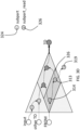
FIG. 5 illustrates COI analysis starting from decoder inputs and stopping at encoder and control logic outputs in accordance with a preferred embodiment of the present invention. -
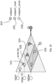
FIG. 6 illustrates that the intersection of FanoutCOI and FaninCOI in the present invention identifies the protected control logic without the need of defining stop points for the control logic. - An integrated circuit design can be considered as a hardware component, having a plurality of parts and a plurality of subparts. Subparts maybe grouped into safety mechanism and intended functionality where two such groups may form a safety feature.
- An example of a safety feature is error correction code ("ECC") protected first-in-fist-out ("FIFO"), which is illustrated in
FIG. 2A . In the safety mechanism group, data inputs are encoded byencoder 210. The encoded data inputs are supplied toECC memory 212 in the safety mechanism group and todata memory 222 in the intended function group. The outputs of theECC memory 212 and thedata memory 222 are combined and decoded withdecoder 214 in the safety mechanism group to produce data outputs and diagnostic outputs. - A lockstep core safety mechanism is illustrated in
FIG. 2B . Core inputs are provided to thecore 240 in the intended function group. Shadow core inputs are provided to theshadow core 230 in the safety mechanism. The shadow core outputs and the core outputs are compared in thecomparator 232 in the safety mechanism to produce diagnostic outputs. As shown inFIG. 2C , however, some logic may remain unprotected by such a safety mechanism. - Accurate extraction of a subpart, or set of basic design elements, is non-trivial. Basic design elements may include, for example, bits, states, ports, signals, wires, gates or cells. Extraction of a subpart and determination of where the safety mechanism or protected logic begins and/or ends in accordance with a preferred embodiment of the present invention is described with reference to
FIGs. 3A-3G . Generally, in the method of the present invention a processor automatically generates a computed first set of basic design elements by intersecting two transitive cones of influence, wherein a first cone of influence is a transitive fanin cone of influence starting from a first point ("TO elements") and a second cone of influence is a transitive fanout cone of influence starting from an second point ("FROM elements"). While the example shown inFIGs. 3A-3G have only a single TOelement 310, more than one TOelement 310 may be included. As shown inFIG. 3A , there is a first point or "TO"element 310 from which a transitive fanin cone ofinfluence 320 is extracted. As shown inFIG. 3B , thesubpart 322 initially is identified asdesign elements influence 320. The cone ofinfluence 320 stops atTO elements - In the next step shown in
FIG. 3C , theTO element 330 from a different subpart becomes aFROM element 330a for this subpart, and a second cone ofinfluence 340 is a transitive fanout cone of influence of FROMelement 330a. This second cone ofinfluence 340, i.e., the transitive fanout, overlays the first cone ofinfluence 320. The intersection of these two cones of influence provides a more precisely defined computed subpart or set 324 ofbasic design elements subpart 324 and may generate a fault list for the basic design elements insubpart 324. - The processor identifies or extracts elements (logic) in the computed subpart or set 324 (
FIG. 3C ) ofbasic design elements FIG. 3D ) and intersecting it with the subpart 324 (FIG. 3C ). Theseelements FIG. 3D ). The TO element(s) of the first cone of influence and FROM element(s) of the second cone of influence may be included in the computedsubpart 324. In one preferred embodiment, the TO element(s) are included insubpart 324 while the FROM elements are not include insubpart 324. - As shown in
FIG. 3D , the processor also identifies allbasic design elements 319, called "read bits," which are in the direct fanout of subpart 324 (FIG. 3C ) and are not TOelement 310 or direct fanout ofTO element 310. In other words, these read elements are elements that are not in the sub-part but read other elements in the sub-part. These read elements are for example not protected by a safety mechanism. - As shown in
FIG. 3E , the subpart 322 (FIG. 3B ) also contains potential residual logic, referred to collectively assubpart_write 328, that controls thesubpart 324. Theelement 315 that writes to elements in thesubpart 324 can be referred to as a "write bit" 315 (FIG. 3F ). These write bits are in the direct fanin of any elements composing subpart 324 (FIG. 3C ) and are extracted as such. - The subpart _write 328 (
FIG 3E ) may be considered as the transitive fanin cone ofwrite bit 315 that does not include TO or cone elements of other subparts.The processor identifies or extracts thesubpart _write 328 for example as potential residual logic or elements. - The processor may subtract the
subpart_read 326 from thesubpart 324, i.e., the computed first set of basic design elements, to generate another subpart of set of basic design elements, so that, for example subpart_read is considered to contain potentially protected elements whereas this new subpart contains protected logic or elements. - Looking now at the invention in the context of a memory, an error code correction ("ECC") protected first-in first-out ("FIFO") design in accordance with the present invention is illustrated in
FIG. 4 . The design can be considered as a hardware part consisting of a number of subparts, including the hamming encoder and decoder, which enable double-bit memory error detection, and single-bit memory error correction, and the flip-flops (FFs) or memory, which store the encoded FIFO entries, including the ECC bits. The encoder and decoder subparts implement the safety mechanism (SM) protecting the memory. The control logic, which manages the FIFO read and write pointers, and the full and empty flags, is another subpart. This subpart is not protected by any SM. - To apply COI analysis and extraction on the ECC FIFO design, a set of first points ("TO elements") must be defined for each subpart. The population of faults that are protected by the ECC SM can be extracted using the inputs of the decoder, marked as "DI" in
FIG. 4 , as TO elements. The transitive fan-in cone is extracted, and a fault list is generated. This step ensures that only faults that structurally propagate to at least one TO element are included in the faults list. - As shown in
FIG. 4 , the resulting list will include all faults in logic outside the decoder. This is an over approximation as, for example, faults in the control logic are not protected by the SM. Using this list, time and resources will be wasted simulating and debugging control logic faults that will always escape detection from the SM, regardless of the stimulus applied. - The basic COI analysis method can be significantly improved by introducing stop points, illustrated in
FIG. 5 as "EO" (encoder outputs) and "CO" (control logic outputs). EO and CO are used as stop points during the COI analysis starting from the decoder inputs DI. This leads to a more precise list, which does not include faults in the control logic. It is worth noting that stop points can also be used as TO elements for the COI analysis and extraction of the fault lists for the encoder and control logic subparts. Using this observation, the need for specifying stop points can be eliminated. When doing COI analysis for a certain subpart, all TO elements of the other subparts can be used as stop points during the current analysis. This idea enhances basic COI analysis, enabling the extraction of more precise fault lists for each subpart. Assuming correct specification of the TO elements for all subparts, we can immediately deduce, without running any fault simulation, that all faults in the FFs subpart are detected, while all faults in the control logic subpart are undetected. - SAHP produces more precise results compared to basic COI analysis and extraction. However, it does rely on correct identification of TO elements for each subpart, which might be difficult in some cases. Identifying the TO elements of the control logic subpart (CO in
FIG. 5 ), for example, is not trivial as this logic is not isolated in a separate module. - This challenge can be addressed by introducing the new concept of FROM elements. In addition to extracting the transitive fan-in cone from the TO elements, DI in the ECC FIFO example, we also consider the points where the protection by the SM starts, EO in the ECC FIFO example.
- Unlike previously introduced stop points, FROM elements do not only act as stop points but are also used as TO elements for a transitive fan-out COI analysis and extraction. Intersecting the transitive fan-out of EO (FanoutCOI in
FIG. 6 ) with the transitive fan-in of DI (FaninCOI inFIG. 4 ) provides the exact list of faults that are protected by the SM. Crucially, this result is achieved without the need for defining CO as stop points or relying or any hierarchical IC design information during the COI analysis of the FFs subpart. It is worth noting that the CO points inFIG 5 are the write bits of the FFs subpart and subsequentially the write subpart of the FF subpart contains the control logic. Read bits and read subparts would work in a similar way but are not demonstrated within this example. - Similar to the TO elements, FROM elements must be associated with the subpart under analysis. It is preferable to define FROM elements that are also TO elements for one or more other subparts. This reduces the total number of points that need to be defined and ensures that the analysis of all subparts covers the entire circuit. Moreover, TO elements can be used as stop points during the transitive fan-out cone extraction, although this is not required. During the analysis of a subpart, TO and FROM elements of all other subparts can be used to speed-up the extraction of the fault list.
- The SAHP method provides more accurate fault lists compared to basic COI analysis and extraction. This eliminates the need to simulate numerous faults, resulting in significant effort and computational savings. SAHP can be applied using FROM elements or stop points. The two approaches can also be combined. Using FROM elements is preferred as results are more accurate, particularly in designs with complex control logic where only the data path logic is protected by a SM.
- The foregoing description of the preferred embodiment of the invention has been presented for purposes of illustration and description. It is not intended to be exhaustive or to limit the invention to the precise form disclosed. The scope of the invention is defined by the appended claims.
Claims (11)
- Method for performing a safety analysis of an integrated circuit based on a safety-specific design structural analysis and cone of influence comprising:
generating with a processor a computed first set (324) of basic design elements (311, 312, 313, 314) by intersecting two transitive cones of influence (320, 340), wherein a first cone of influence (320) is a transitive fanin cone of influence starting from at least one first point (310), corresponding to at least one TO element, and a second cone of influence (340) is a transitive fanout cone of influence starting from at least one second point (330a), corresponding to at least one FROM element, wherein the second cone (340) of influence overlays the first cone (320) of influence, identifying, by the processor, all basic design elements (319) which are in the direct fanout of the first set (324) of basic design elements and are not the first point (310) or direct fanout of the first point (310) and which are not protected by the safety mechanism. - Method for performing a safety analysis of an integrated circuit based on a safety-specific design structural analysis and cone of influence according to claim 1, further comprising:
extracting, with the processor, from the computed first set (324) of basic design elements a second set (328) of basic design elements that are in a direct fanin of the computed first set (320) of basic design elements. - Method for performing a safety analysis of an integrated circuit based on a safety-specific design structural analysis and cone of influence according to claim 2, wherein said second set (328) of basic design elements are not second points (330a), corresponding to FROM elements, of the first cone of influence (320).
- Method for performing a safety analysis of an integrated circuit based on a safety-specific design structural analysis and cone of influence according to any one of claims 1 to 3, further comprising:
extracting, with said processor, from the computed first set (324) of basic design elements a third set (319) of basic design elements that are in a direct fanout of the computed first set (324) of basic design elements. - Method for performing a safety analysis of an integrated circuit based on a safety-specific design structural analysis and cone of influence according to claim 4, wherein said third set (319) of basic design elements are not first points, corresponding to TO elements, of the first cone of influence (320) or elements in the direct fanout of the first points, corresponding to the TO elements, of the first cone (320).
- Method for performing a safety analysis of an integrated circuit based on a safety-specific design structural analysis and cone of influence according to any one of claims 4 to 5, further comprising:
generating with said processor a computed fourth set (326) of basic design elements, wherein said fourth set (326) of basic design elements comprises elements from said first computed set (324) that are inside a transitive fanin cone of the third set of basic design elements. - Method for performing a safety analysis of an integrated circuit based on a safety-specific design structural analysis and cone of influence according to claim 6, further comprising:
subtracting with said processor the fourth set (326) of basic design elements from the computed first set (324) of basic design elements to generate a fifth computed set of basic design elements. - Method for performing a safety analysis of an integrated circuit based on a safety-specific design structural analysis and cone of influence according to any one of claims 2 to 7, further comprising:
generating with said processor a computed a sixth set (328) of basic design elements, wherein said sixth computed set of basic design elements comprises elements that are inside a transitive fanin cone of the second set of basic design elements - Method for performing a safety analysis of an integrated circuit based on a safety-specific design structural analysis and cone of influence according to any one of claims 1 to 8, further comprising:
calculating a size of logic represented by the computed first set (324) of basic design elements. - Method for performing a safety analysis of an integrated circuit based on a safety-specific design structural analysis and cone of influence according to any one of claims 1 to 9, further comprising:
generating a fault list for the computed first set (324) of basic design elements. - Method for performing a safety analysis of an integrated circuit based on a safety-specific design structural analysis and cone of influence according to any one of claims 1 to 10, wherein at least one of said at least one first point, corresponding to at least one TO element, and said at least one second point, corresponding to at least one FROM element, is included in said computed first set (324) of basic design elements.
Applications Claiming Priority (1)
| Application Number | Priority Date | Filing Date | Title |
|---|---|---|---|
| US201962895178P | 2019-09-03 | 2019-09-03 |
Publications (2)
| Publication Number | Publication Date |
|---|---|
| EP3789780A1 EP3789780A1 (en) | 2021-03-10 |
| EP3789780B1 true EP3789780B1 (en) | 2024-03-27 |
Family
ID=72355875
Family Applications (1)
| Application Number | Title | Priority Date | Filing Date |
|---|---|---|---|
| EP20194308.1A Active EP3789780B1 (en) | 2019-09-03 | 2020-09-03 | Method to perform hardware safety analysis based on a structural analysis and cones of influence |
Country Status (2)
| Country | Link |
|---|---|
| US (1) | US11250198B2 (en) |
| EP (1) | EP3789780B1 (en) |
Families Citing this family (5)
| Publication number | Priority date | Publication date | Assignee | Title |
|---|---|---|---|---|
| US12307178B2 (en) * | 2021-02-25 | 2025-05-20 | Synopsys, Inc. | Structural analysis for determining fault types in safety related logic |
| US12423491B2 (en) * | 2021-05-26 | 2025-09-23 | Synopsys, Inc. | Identifying association of safety related ports to their safety mechanisms through structural analysis |
| WO2023272424A1 (en) * | 2021-06-28 | 2023-01-05 | 华为技术有限公司 | Circuit verification method and apparatus based on automatic test pattern generation |
| DE102023203372A1 (en) | 2023-04-13 | 2024-10-17 | Siemens Electronic Design Automation Gmbh | Verifying functional safety of an integrated circuit |
| CN120917447A (en) | 2023-04-13 | 2025-11-07 | 西门子电子设计自动化有限公司 | Verifying functional security of integrated circuits |
Family Cites Families (5)
| Publication number | Priority date | Publication date | Assignee | Title |
|---|---|---|---|---|
| FR2798472B1 (en) * | 1999-09-15 | 2001-12-14 | Centre Nat Etd Spatiales | METHOD FOR LOCATING DEFECTIVE ELEMENTS IN AN INTEGRATED CIRCUIT |
| WO2004113942A1 (en) * | 2003-06-20 | 2004-12-29 | Credence Systems Corporation | Method for fault localization in circuits |
| US7555689B2 (en) * | 2005-06-28 | 2009-06-30 | Dhiraj Goswami | Generating responses to patterns stimulating an electronic circuit with timing exception paths |
| CN102879731B (en) | 2012-09-26 | 2015-10-28 | 清华大学 | A kind of method of testing of digital integrated circuit |
| US9244125B2 (en) * | 2012-10-25 | 2016-01-26 | Mentor Graphics Corporation | Dynamic design partitioning for scan chain diagnosis |
-
2020
- 2020-09-03 US US17/011,204 patent/US11250198B2/en active Active
- 2020-09-03 EP EP20194308.1A patent/EP3789780B1/en active Active
Also Published As
| Publication number | Publication date |
|---|---|
| US11250198B2 (en) | 2022-02-15 |
| EP3789780A1 (en) | 2021-03-10 |
| US20210064810A1 (en) | 2021-03-04 |
Similar Documents
| Publication | Publication Date | Title |
|---|---|---|
| US11250198B2 (en) | Method to perform hardware safety analysis without fault simulation | |
| US6292765B1 (en) | Method for automatically searching for functional defects in a description of a circuit | |
| CN105631077B (en) | Integrated circuit with increased fault coverage | |
| CN104215895B (en) | Hardware Trojan horse detection method and hardware Trojan horse detection system based on test vectors | |
| Huang et al. | Statistical diagnosis for intermittent scan chain hold-time fault | |
| Chappell et al. | LAMP: Logic‐Circuit Simulators | |
| US6453437B1 (en) | Method and system for performing transition fault simulation along long circuit paths for high-quality automatic test pattern generation | |
| Barbirotta et al. | Fault resilience analysis of a RISC-V microprocessor design through a dedicated UVM environment | |
| US12307178B2 (en) | Structural analysis for determining fault types in safety related logic | |
| US20220128628A1 (en) | Single-pass diagnosis for multiple chain defects | |
| CN118940687A (en) | Chip security design method, electronic device and storage medium | |
| Mao et al. | Improving gate level fault coverage by RTL fault grading | |
| CN110377924B (en) | Hard error simulation and use thereof | |
| Khatri et al. | RASP-FIT: A fast and automatic fault injection tool for code-modification of FPGA designs | |
| US11288428B1 (en) | Integrated circuit design modification for localization of scan chain defects | |
| US6546514B1 (en) | Integrated circuit analysis and design involving defective circuit element replacement on a netlist | |
| Le et al. | Scalable fault localization for SystemC TLM designs | |
| Mogollón et al. | Metrics for the measurement of the quality of stimuli in radiation testing using fast hardware emulation | |
| Khatri et al. | Validation of selecting SP-values for fault models under proposed RASP-FIT tool | |
| CN112798944A (en) | FPGA hardware error attribution analysis method based on online real-time data | |
| US12481813B2 (en) | Test point insertion in analog circuit design testing | |
| Khatri | Development, Verification and Analysis of a Fault Injection Tool for Improving Dependability of FPGA Systems | |
| Takahashi et al. | Diagnosis of single gate delay faults in combinational circuits using delay fault simulation | |
| François et al. | Characterization-Guided Strategies for Transients Faults Mitigation in Digitals Circuits | |
| CN109144854A (en) | A kind of software self-test method using Bounded Model detection for gate level circuit |
Legal Events
| Date | Code | Title | Description |
|---|---|---|---|
| PUAI | Public reference made under article 153(3) epc to a published international application that has entered the european phase |
Free format text: ORIGINAL CODE: 0009012 |
|
| STAA | Information on the status of an ep patent application or granted ep patent |
Free format text: STATUS: THE APPLICATION HAS BEEN PUBLISHED |
|
| AK | Designated contracting states |
Kind code of ref document: A1 Designated state(s): AL AT BE BG CH CY CZ DE DK EE ES FI FR GB GR HR HU IE IS IT LI LT LU LV MC MK MT NL NO PL PT RO RS SE SI SK SM TR |
|
| AX | Request for extension of the european patent |
Extension state: BA ME |
|
| STAA | Information on the status of an ep patent application or granted ep patent |
Free format text: STATUS: REQUEST FOR EXAMINATION WAS MADE |
|
| 17P | Request for examination filed |
Effective date: 20210909 |
|
| RBV | Designated contracting states (corrected) |
Designated state(s): AL AT BE BG CH CY CZ DE DK EE ES FI FR GB GR HR HU IE IS IT LI LT LU LV MC MK MT NL NO PL PT RO RS SE SI SK SM TR |
|
| RAP3 | Party data changed (applicant data changed or rights of an application transferred) |
Owner name: ONESPIN SOLUTIONS GMBH |
|
| RAP1 | Party data changed (applicant data changed or rights of an application transferred) |
Owner name: SIEMENS ELECTRONIC DESIGN AUTOMATION GMBH |
|
| GRAP | Despatch of communication of intention to grant a patent |
Free format text: ORIGINAL CODE: EPIDOSNIGR1 |
|
| STAA | Information on the status of an ep patent application or granted ep patent |
Free format text: STATUS: GRANT OF PATENT IS INTENDED |
|
| INTG | Intention to grant announced |
Effective date: 20231106 |
|
| GRAS | Grant fee paid |
Free format text: ORIGINAL CODE: EPIDOSNIGR3 |
|
| GRAA | (expected) grant |
Free format text: ORIGINAL CODE: 0009210 |
|
| STAA | Information on the status of an ep patent application or granted ep patent |
Free format text: STATUS: THE PATENT HAS BEEN GRANTED |
|
| AK | Designated contracting states |
Kind code of ref document: B1 Designated state(s): AL AT BE BG CH CY CZ DE DK EE ES FI FR GB GR HR HU IE IS IT LI LT LU LV MC MK MT NL NO PL PT RO RS SE SI SK SM TR |
|
| REG | Reference to a national code |
Ref country code: GB Ref legal event code: FG4D |
|
| REG | Reference to a national code |
Ref country code: CH Ref legal event code: EP |
|
| REG | Reference to a national code |
Ref country code: DE Ref legal event code: R096 Ref document number: 602020027820 Country of ref document: DE |
|
| REG | Reference to a national code |
Ref country code: IE Ref legal event code: FG4D |
|
| PG25 | Lapsed in a contracting state [announced via postgrant information from national office to epo] |
Ref country code: LT Free format text: LAPSE BECAUSE OF FAILURE TO SUBMIT A TRANSLATION OF THE DESCRIPTION OR TO PAY THE FEE WITHIN THE PRESCRIBED TIME-LIMIT Effective date: 20240327 |
|
| REG | Reference to a national code |
Ref country code: LT Ref legal event code: MG9D |
|
| PG25 | Lapsed in a contracting state [announced via postgrant information from national office to epo] |
Ref country code: GR Free format text: LAPSE BECAUSE OF FAILURE TO SUBMIT A TRANSLATION OF THE DESCRIPTION OR TO PAY THE FEE WITHIN THE PRESCRIBED TIME-LIMIT Effective date: 20240628 |
|
| PG25 | Lapsed in a contracting state [announced via postgrant information from national office to epo] |
Ref country code: HR Free format text: LAPSE BECAUSE OF FAILURE TO SUBMIT A TRANSLATION OF THE DESCRIPTION OR TO PAY THE FEE WITHIN THE PRESCRIBED TIME-LIMIT Effective date: 20240327 Ref country code: RS Free format text: LAPSE BECAUSE OF FAILURE TO SUBMIT A TRANSLATION OF THE DESCRIPTION OR TO PAY THE FEE WITHIN THE PRESCRIBED TIME-LIMIT Effective date: 20240627 |
|
| PG25 | Lapsed in a contracting state [announced via postgrant information from national office to epo] |
Ref country code: RS Free format text: LAPSE BECAUSE OF FAILURE TO SUBMIT A TRANSLATION OF THE DESCRIPTION OR TO PAY THE FEE WITHIN THE PRESCRIBED TIME-LIMIT Effective date: 20240627 Ref country code: NO Free format text: LAPSE BECAUSE OF FAILURE TO SUBMIT A TRANSLATION OF THE DESCRIPTION OR TO PAY THE FEE WITHIN THE PRESCRIBED TIME-LIMIT Effective date: 20240627 Ref country code: LT Free format text: LAPSE BECAUSE OF FAILURE TO SUBMIT A TRANSLATION OF THE DESCRIPTION OR TO PAY THE FEE WITHIN THE PRESCRIBED TIME-LIMIT Effective date: 20240327 Ref country code: HR Free format text: LAPSE BECAUSE OF FAILURE TO SUBMIT A TRANSLATION OF THE DESCRIPTION OR TO PAY THE FEE WITHIN THE PRESCRIBED TIME-LIMIT Effective date: 20240327 Ref country code: GR Free format text: LAPSE BECAUSE OF FAILURE TO SUBMIT A TRANSLATION OF THE DESCRIPTION OR TO PAY THE FEE WITHIN THE PRESCRIBED TIME-LIMIT Effective date: 20240628 Ref country code: FI Free format text: LAPSE BECAUSE OF FAILURE TO SUBMIT A TRANSLATION OF THE DESCRIPTION OR TO PAY THE FEE WITHIN THE PRESCRIBED TIME-LIMIT Effective date: 20240327 Ref country code: BG Free format text: LAPSE BECAUSE OF FAILURE TO SUBMIT A TRANSLATION OF THE DESCRIPTION OR TO PAY THE FEE WITHIN THE PRESCRIBED TIME-LIMIT Effective date: 20240327 |
|
| REG | Reference to a national code |
Ref country code: NL Ref legal event code: MP Effective date: 20240327 |
|
| PG25 | Lapsed in a contracting state [announced via postgrant information from national office to epo] |
Ref country code: SE Free format text: LAPSE BECAUSE OF FAILURE TO SUBMIT A TRANSLATION OF THE DESCRIPTION OR TO PAY THE FEE WITHIN THE PRESCRIBED TIME-LIMIT Effective date: 20240327 Ref country code: LV Free format text: LAPSE BECAUSE OF FAILURE TO SUBMIT A TRANSLATION OF THE DESCRIPTION OR TO PAY THE FEE WITHIN THE PRESCRIBED TIME-LIMIT Effective date: 20240327 |
|
| PG25 | Lapsed in a contracting state [announced via postgrant information from national office to epo] |
Ref country code: NL Free format text: LAPSE BECAUSE OF FAILURE TO SUBMIT A TRANSLATION OF THE DESCRIPTION OR TO PAY THE FEE WITHIN THE PRESCRIBED TIME-LIMIT Effective date: 20240327 |
|
| REG | Reference to a national code |
Ref country code: AT Ref legal event code: MK05 Ref document number: 1670415 Country of ref document: AT Kind code of ref document: T Effective date: 20240327 |
|
| PG25 | Lapsed in a contracting state [announced via postgrant information from national office to epo] |
Ref country code: NL Free format text: LAPSE BECAUSE OF FAILURE TO SUBMIT A TRANSLATION OF THE DESCRIPTION OR TO PAY THE FEE WITHIN THE PRESCRIBED TIME-LIMIT Effective date: 20240327 |
|
| PG25 | Lapsed in a contracting state [announced via postgrant information from national office to epo] |
Ref country code: IS Free format text: LAPSE BECAUSE OF FAILURE TO SUBMIT A TRANSLATION OF THE DESCRIPTION OR TO PAY THE FEE WITHIN THE PRESCRIBED TIME-LIMIT Effective date: 20240727 |
|
| PG25 | Lapsed in a contracting state [announced via postgrant information from national office to epo] |
Ref country code: SM Free format text: LAPSE BECAUSE OF FAILURE TO SUBMIT A TRANSLATION OF THE DESCRIPTION OR TO PAY THE FEE WITHIN THE PRESCRIBED TIME-LIMIT Effective date: 20240327 Ref country code: PT Free format text: LAPSE BECAUSE OF FAILURE TO SUBMIT A TRANSLATION OF THE DESCRIPTION OR TO PAY THE FEE WITHIN THE PRESCRIBED TIME-LIMIT Effective date: 20240729 |
|
| PG25 | Lapsed in a contracting state [announced via postgrant information from national office to epo] |
Ref country code: ES Free format text: LAPSE BECAUSE OF FAILURE TO SUBMIT A TRANSLATION OF THE DESCRIPTION OR TO PAY THE FEE WITHIN THE PRESCRIBED TIME-LIMIT Effective date: 20240327 |
|
| PG25 | Lapsed in a contracting state [announced via postgrant information from national office to epo] |
Ref country code: EE Free format text: LAPSE BECAUSE OF FAILURE TO SUBMIT A TRANSLATION OF THE DESCRIPTION OR TO PAY THE FEE WITHIN THE PRESCRIBED TIME-LIMIT Effective date: 20240327 Ref country code: CZ Free format text: LAPSE BECAUSE OF FAILURE TO SUBMIT A TRANSLATION OF THE DESCRIPTION OR TO PAY THE FEE WITHIN THE PRESCRIBED TIME-LIMIT Effective date: 20240327 |
|
| PG25 | Lapsed in a contracting state [announced via postgrant information from national office to epo] |
Ref country code: AT Free format text: LAPSE BECAUSE OF FAILURE TO SUBMIT A TRANSLATION OF THE DESCRIPTION OR TO PAY THE FEE WITHIN THE PRESCRIBED TIME-LIMIT Effective date: 20240327 |
|
| PG25 | Lapsed in a contracting state [announced via postgrant information from national office to epo] |
Ref country code: PL Free format text: LAPSE BECAUSE OF FAILURE TO SUBMIT A TRANSLATION OF THE DESCRIPTION OR TO PAY THE FEE WITHIN THE PRESCRIBED TIME-LIMIT Effective date: 20240327 |
|
| PG25 | Lapsed in a contracting state [announced via postgrant information from national office to epo] |
Ref country code: SK Free format text: LAPSE BECAUSE OF FAILURE TO SUBMIT A TRANSLATION OF THE DESCRIPTION OR TO PAY THE FEE WITHIN THE PRESCRIBED TIME-LIMIT Effective date: 20240327 |
|
| PG25 | Lapsed in a contracting state [announced via postgrant information from national office to epo] |
Ref country code: SM Free format text: LAPSE BECAUSE OF FAILURE TO SUBMIT A TRANSLATION OF THE DESCRIPTION OR TO PAY THE FEE WITHIN THE PRESCRIBED TIME-LIMIT Effective date: 20240327 Ref country code: SK Free format text: LAPSE BECAUSE OF FAILURE TO SUBMIT A TRANSLATION OF THE DESCRIPTION OR TO PAY THE FEE WITHIN THE PRESCRIBED TIME-LIMIT Effective date: 20240327 Ref country code: RO Free format text: LAPSE BECAUSE OF FAILURE TO SUBMIT A TRANSLATION OF THE DESCRIPTION OR TO PAY THE FEE WITHIN THE PRESCRIBED TIME-LIMIT Effective date: 20240327 Ref country code: PT Free format text: LAPSE BECAUSE OF FAILURE TO SUBMIT A TRANSLATION OF THE DESCRIPTION OR TO PAY THE FEE WITHIN THE PRESCRIBED TIME-LIMIT Effective date: 20240729 Ref country code: PL Free format text: LAPSE BECAUSE OF FAILURE TO SUBMIT A TRANSLATION OF THE DESCRIPTION OR TO PAY THE FEE WITHIN THE PRESCRIBED TIME-LIMIT Effective date: 20240327 Ref country code: IS Free format text: LAPSE BECAUSE OF FAILURE TO SUBMIT A TRANSLATION OF THE DESCRIPTION OR TO PAY THE FEE WITHIN THE PRESCRIBED TIME-LIMIT Effective date: 20240727 Ref country code: ES Free format text: LAPSE BECAUSE OF FAILURE TO SUBMIT A TRANSLATION OF THE DESCRIPTION OR TO PAY THE FEE WITHIN THE PRESCRIBED TIME-LIMIT Effective date: 20240327 Ref country code: EE Free format text: LAPSE BECAUSE OF FAILURE TO SUBMIT A TRANSLATION OF THE DESCRIPTION OR TO PAY THE FEE WITHIN THE PRESCRIBED TIME-LIMIT Effective date: 20240327 Ref country code: CZ Free format text: LAPSE BECAUSE OF FAILURE TO SUBMIT A TRANSLATION OF THE DESCRIPTION OR TO PAY THE FEE WITHIN THE PRESCRIBED TIME-LIMIT Effective date: 20240327 Ref country code: AT Free format text: LAPSE BECAUSE OF FAILURE TO SUBMIT A TRANSLATION OF THE DESCRIPTION OR TO PAY THE FEE WITHIN THE PRESCRIBED TIME-LIMIT Effective date: 20240327 |
|
| REG | Reference to a national code |
Ref country code: DE Ref legal event code: R097 Ref document number: 602020027820 Country of ref document: DE |
|
| PG25 | Lapsed in a contracting state [announced via postgrant information from national office to epo] |
Ref country code: DK Free format text: LAPSE BECAUSE OF FAILURE TO SUBMIT A TRANSLATION OF THE DESCRIPTION OR TO PAY THE FEE WITHIN THE PRESCRIBED TIME-LIMIT Effective date: 20240327 |
|
| PG25 | Lapsed in a contracting state [announced via postgrant information from national office to epo] |
Ref country code: DK Free format text: LAPSE BECAUSE OF FAILURE TO SUBMIT A TRANSLATION OF THE DESCRIPTION OR TO PAY THE FEE WITHIN THE PRESCRIBED TIME-LIMIT Effective date: 20240327 |
|
| PLBE | No opposition filed within time limit |
Free format text: ORIGINAL CODE: 0009261 |
|
| STAA | Information on the status of an ep patent application or granted ep patent |
Free format text: STATUS: NO OPPOSITION FILED WITHIN TIME LIMIT |
|
| 26N | No opposition filed |
Effective date: 20250103 |
|
| PG25 | Lapsed in a contracting state [announced via postgrant information from national office to epo] |
Ref country code: MC Free format text: LAPSE BECAUSE OF FAILURE TO SUBMIT A TRANSLATION OF THE DESCRIPTION OR TO PAY THE FEE WITHIN THE PRESCRIBED TIME-LIMIT Effective date: 20240327 Ref country code: SI Free format text: LAPSE BECAUSE OF FAILURE TO SUBMIT A TRANSLATION OF THE DESCRIPTION OR TO PAY THE FEE WITHIN THE PRESCRIBED TIME-LIMIT Effective date: 20240327 |
|
| REG | Reference to a national code |
Ref country code: CH Ref legal event code: PL |
|
| PG25 | Lapsed in a contracting state [announced via postgrant information from national office to epo] |
Ref country code: LU Free format text: LAPSE BECAUSE OF NON-PAYMENT OF DUE FEES Effective date: 20240903 |
|
| REG | Reference to a national code |
Ref country code: BE Ref legal event code: MM Effective date: 20240930 |
|
| PG25 | Lapsed in a contracting state [announced via postgrant information from national office to epo] |
Ref country code: BE Free format text: LAPSE BECAUSE OF NON-PAYMENT OF DUE FEES Effective date: 20240930 |
|
| PG25 | Lapsed in a contracting state [announced via postgrant information from national office to epo] |
Ref country code: CH Free format text: LAPSE BECAUSE OF NON-PAYMENT OF DUE FEES Effective date: 20240930 |
|
| PG25 | Lapsed in a contracting state [announced via postgrant information from national office to epo] |
Ref country code: IE Free format text: LAPSE BECAUSE OF NON-PAYMENT OF DUE FEES Effective date: 20240903 |
|
| PGFP | Annual fee paid to national office [announced via postgrant information from national office to epo] |
Ref country code: IT Payment date: 20250924 Year of fee payment: 6 |
|
| PGFP | Annual fee paid to national office [announced via postgrant information from national office to epo] |
Ref country code: FR Payment date: 20250915 Year of fee payment: 6 |
|
| PGFP | Annual fee paid to national office [announced via postgrant information from national office to epo] |
Ref country code: DE Payment date: 20251120 Year of fee payment: 6 |
|
| PGFP | Annual fee paid to national office [announced via postgrant information from national office to epo] |
Ref country code: GB Payment date: 20251002 Year of fee payment: 6 |
|
| PG25 | Lapsed in a contracting state [announced via postgrant information from national office to epo] |
Ref country code: CY Free format text: LAPSE BECAUSE OF FAILURE TO SUBMIT A TRANSLATION OF THE DESCRIPTION OR TO PAY THE FEE WITHIN THE PRESCRIBED TIME-LIMIT; INVALID AB INITIO Effective date: 20200903 |
|
| PG25 | Lapsed in a contracting state [announced via postgrant information from national office to epo] |
Ref country code: HU Free format text: LAPSE BECAUSE OF FAILURE TO SUBMIT A TRANSLATION OF THE DESCRIPTION OR TO PAY THE FEE WITHIN THE PRESCRIBED TIME-LIMIT; INVALID AB INITIO Effective date: 20200903 |
|
| PG25 | Lapsed in a contracting state [announced via postgrant information from national office to epo] |
Ref country code: TR Free format text: LAPSE BECAUSE OF FAILURE TO SUBMIT A TRANSLATION OF THE DESCRIPTION OR TO PAY THE FEE WITHIN THE PRESCRIBED TIME-LIMIT Effective date: 20240327 |
|
| REG | Reference to a national code |
Ref country code: DE Ref legal event code: R081 Ref document number: 602020027820 Country of ref document: DE Owner name: SIEMENS INDUSTRY SOFTWARE INC., US Free format text: FORMER OWNER: SIEMENS ELECTRONIC DESIGN AUTOMATION GMBH, 80634 MUENCHEN, DE |