EP3789662B1 - Vehicle lighting assembly with lens heating device and receptacle connector assembly for same - Google Patents
Vehicle lighting assembly with lens heating device and receptacle connector assembly for same Download PDFInfo
- Publication number
- EP3789662B1 EP3789662B1 EP20194032.7A EP20194032A EP3789662B1 EP 3789662 B1 EP3789662 B1 EP 3789662B1 EP 20194032 A EP20194032 A EP 20194032A EP 3789662 B1 EP3789662 B1 EP 3789662B1
- Authority
- EP
- European Patent Office
- Prior art keywords
- terminal
- terminal housing
- connection portion
- oval
- lighting assembly
- Prior art date
- Legal status (The legal status is an assumption and is not a legal conclusion. Google has not performed a legal analysis and makes no representation as to the accuracy of the status listed.)
- Active
Links
Images



Classifications
-
- F—MECHANICAL ENGINEERING; LIGHTING; HEATING; WEAPONS; BLASTING
- F21—LIGHTING
- F21S—NON-PORTABLE LIGHTING DEVICES; SYSTEMS THEREOF; VEHICLE LIGHTING DEVICES SPECIALLY ADAPTED FOR VEHICLE EXTERIORS
- F21S45/00—Arrangements within vehicle lighting devices specially adapted for vehicle exteriors, for purposes other than emission or distribution of light
- F21S45/60—Heating of lighting devices, e.g. for demisting
-
- B—PERFORMING OPERATIONS; TRANSPORTING
- B60—VEHICLES IN GENERAL
- B60S—SERVICING, CLEANING, REPAIRING, SUPPORTING, LIFTING, OR MANOEUVRING OF VEHICLES, NOT OTHERWISE PROVIDED FOR
- B60S1/00—Cleaning of vehicles
- B60S1/02—Cleaning windscreens, windows or optical devices
- B60S1/023—Cleaning windscreens, windows or optical devices including defroster or demisting means
- B60S1/026—Cleaning windscreens, windows or optical devices including defroster or demisting means using electrical means
-
- F—MECHANICAL ENGINEERING; LIGHTING; HEATING; WEAPONS; BLASTING
- F21—LIGHTING
- F21V—FUNCTIONAL FEATURES OR DETAILS OF LIGHTING DEVICES OR SYSTEMS THEREOF; STRUCTURAL COMBINATIONS OF LIGHTING DEVICES WITH OTHER ARTICLES, NOT OTHERWISE PROVIDED FOR
- F21V21/00—Supporting, suspending, or attaching arrangements for lighting devices; Hand grips
- F21V21/002—Supporting, suspending, or attaching arrangements for lighting devices; Hand grips making direct electrical contact, e.g. by piercing
-
- H—ELECTRICITY
- H01—ELECTRIC ELEMENTS
- H01R—ELECTRICALLY-CONDUCTIVE CONNECTIONS; STRUCTURAL ASSOCIATIONS OF A PLURALITY OF MUTUALLY-INSULATED ELECTRICAL CONNECTING ELEMENTS; COUPLING DEVICES; CURRENT COLLECTORS
- H01R11/00—Individual connecting elements providing two or more spaced connecting locations for conductive members which are, or may be, thereby interconnected, e.g. end pieces for wires or cables supported by the wire or cable and having means for facilitating electrical connection to some other wire, terminal, or conductive member, blocks of binding posts
- H01R11/11—End pieces or tapping pieces for wires, supported by the wire and for facilitating electrical connection to some other wire, terminal or conductive member
- H01R11/12—End pieces terminating in an eye, hook, or fork
-
- H—ELECTRICITY
- H01—ELECTRIC ELEMENTS
- H01R—ELECTRICALLY-CONDUCTIVE CONNECTIONS; STRUCTURAL ASSOCIATIONS OF A PLURALITY OF MUTUALLY-INSULATED ELECTRICAL CONNECTING ELEMENTS; COUPLING DEVICES; CURRENT COLLECTORS
- H01R13/00—Details of coupling devices of the kinds covered by groups H01R12/70 or H01R24/00 - H01R33/00
- H01R13/02—Contact members
- H01R13/10—Sockets for co-operation with pins or blades
- H01R13/11—Resilient sockets
- H01R13/111—Resilient sockets co-operating with pins having a circular transverse section
-
- H—ELECTRICITY
- H01—ELECTRIC ELEMENTS
- H01R—ELECTRICALLY-CONDUCTIVE CONNECTIONS; STRUCTURAL ASSOCIATIONS OF A PLURALITY OF MUTUALLY-INSULATED ELECTRICAL CONNECTING ELEMENTS; COUPLING DEVICES; CURRENT COLLECTORS
- H01R13/00—Details of coupling devices of the kinds covered by groups H01R12/70 or H01R24/00 - H01R33/00
- H01R13/62—Means for facilitating engagement or disengagement of coupling parts or for holding them in engagement
- H01R13/629—Additional means for facilitating engagement or disengagement of coupling parts, e.g. aligning or guiding means, levers, gas pressure electrical locking indicators, manufacturing tolerances
- H01R13/631—Additional means for facilitating engagement or disengagement of coupling parts, e.g. aligning or guiding means, levers, gas pressure electrical locking indicators, manufacturing tolerances for engagement only
- H01R13/6315—Additional means for facilitating engagement or disengagement of coupling parts, e.g. aligning or guiding means, levers, gas pressure electrical locking indicators, manufacturing tolerances for engagement only allowing relative movement between coupling parts, e.g. floating connection
-
- H—ELECTRICITY
- H05—ELECTRIC TECHNIQUES NOT OTHERWISE PROVIDED FOR
- H05B—ELECTRIC HEATING; ELECTRIC LIGHT SOURCES NOT OTHERWISE PROVIDED FOR; CIRCUIT ARRANGEMENTS FOR ELECTRIC LIGHT SOURCES, IN GENERAL
- H05B3/00—Ohmic-resistance heating
- H05B3/02—Details
- H05B3/06—Heater elements structurally combined with coupling elements or holders
-
- H—ELECTRICITY
- H05—ELECTRIC TECHNIQUES NOT OTHERWISE PROVIDED FOR
- H05B—ELECTRIC HEATING; ELECTRIC LIGHT SOURCES NOT OTHERWISE PROVIDED FOR; CIRCUIT ARRANGEMENTS FOR ELECTRIC LIGHT SOURCES, IN GENERAL
- H05B3/00—Ohmic-resistance heating
- H05B3/02—Details
- H05B3/06—Heater elements structurally combined with coupling elements or holders
- H05B3/08—Heater elements structurally combined with coupling elements or holders having electric connections specially adapted for high temperatures
-
- H—ELECTRICITY
- H05—ELECTRIC TECHNIQUES NOT OTHERWISE PROVIDED FOR
- H05B—ELECTRIC HEATING; ELECTRIC LIGHT SOURCES NOT OTHERWISE PROVIDED FOR; CIRCUIT ARRANGEMENTS FOR ELECTRIC LIGHT SOURCES, IN GENERAL
- H05B3/00—Ohmic-resistance heating
- H05B3/84—Heating arrangements specially adapted for transparent or reflecting areas, e.g. for demisting or de-icing windows, mirrors or vehicle windshields
-
- B—PERFORMING OPERATIONS; TRANSPORTING
- B60—VEHICLES IN GENERAL
- B60Q—ARRANGEMENT OF SIGNALLING OR LIGHTING DEVICES, THE MOUNTING OR SUPPORTING THEREOF OR CIRCUITS THEREFOR, FOR VEHICLES IN GENERAL
- B60Q1/00—Arrangement of optical signalling or lighting devices, the mounting or supporting thereof or circuits therefor
- B60Q1/0017—Devices integrating an element dedicated to another function
-
- F—MECHANICAL ENGINEERING; LIGHTING; HEATING; WEAPONS; BLASTING
- F21—LIGHTING
- F21W—INDEXING SCHEME ASSOCIATED WITH SUBCLASSES F21K, F21L, F21S and F21V, RELATING TO USES OR APPLICATIONS OF LIGHTING DEVICES OR SYSTEMS
- F21W2107/00—Use or application of lighting devices on or in particular types of vehicles
- F21W2107/10—Use or application of lighting devices on or in particular types of vehicles for land vehicles
-
- F—MECHANICAL ENGINEERING; LIGHTING; HEATING; WEAPONS; BLASTING
- F21—LIGHTING
- F21Y—INDEXING SCHEME ASSOCIATED WITH SUBCLASSES F21K, F21L, F21S and F21V, RELATING TO THE FORM OR THE KIND OF THE LIGHT SOURCES OR OF THE COLOUR OF THE LIGHT EMITTED
- F21Y2115/00—Light-generating elements of semiconductor light sources
- F21Y2115/10—Light-emitting diodes [LED]
-
- H—ELECTRICITY
- H01—ELECTRIC ELEMENTS
- H01R—ELECTRICALLY-CONDUCTIVE CONNECTIONS; STRUCTURAL ASSOCIATIONS OF A PLURALITY OF MUTUALLY-INSULATED ELECTRICAL CONNECTING ELEMENTS; COUPLING DEVICES; CURRENT COLLECTORS
- H01R2101/00—One pole
-
- H—ELECTRICITY
- H01—ELECTRIC ELEMENTS
- H01R—ELECTRICALLY-CONDUCTIVE CONNECTIONS; STRUCTURAL ASSOCIATIONS OF A PLURALITY OF MUTUALLY-INSULATED ELECTRICAL CONNECTING ELEMENTS; COUPLING DEVICES; CURRENT COLLECTORS
- H01R2201/00—Connectors or connections adapted for particular applications
-
- H—ELECTRICITY
- H01—ELECTRIC ELEMENTS
- H01R—ELECTRICALLY-CONDUCTIVE CONNECTIONS; STRUCTURAL ASSOCIATIONS OF A PLURALITY OF MUTUALLY-INSULATED ELECTRICAL CONNECTING ELEMENTS; COUPLING DEVICES; CURRENT COLLECTORS
- H01R2201/00—Connectors or connections adapted for particular applications
- H01R2201/26—Connectors or connections adapted for particular applications for vehicles
-
- H—ELECTRICITY
- H05—ELECTRIC TECHNIQUES NOT OTHERWISE PROVIDED FOR
- H05B—ELECTRIC HEATING; ELECTRIC LIGHT SOURCES NOT OTHERWISE PROVIDED FOR; CIRCUIT ARRANGEMENTS FOR ELECTRIC LIGHT SOURCES, IN GENERAL
- H05B2203/00—Aspects relating to Ohmic resistive heating covered by group H05B3/00
- H05B2203/016—Heaters using particular connecting means
Definitions
- the invention generally relates to a lighting assembly for a vehicle, particularly a lighting assembly having a device configured to heat a lens of the lighting assembly.
- Lighting systems that include some form of a head lamps, tail lamps, and side marking lamps.
- Lighting systems that use incandescent or HID bulbs, for example, generate sufficient waste heat so that snow and/or ice does not form or stick on lenses of the lighting system when the ambient temperature is below the freezing temperature of water.
- Snow or ice on the lens of the lighting system may reduce luminous transmittance of the lens, thereby degrading the performance of the lighting system.
- Some lighting systems, such as those using light emitting diode (LED) bulbs do not generate sufficient waste to heat melt ice or snow on the lighting system lens due to their energy efficiency.
- LED light emitting diode
- Publication US 2012/040553 A1 discloses a connector connected to a mating connector, which is fixed in a case of a motor, wherein the connector comprises: an outer housing attached to the case; a first inner housing accommodating a first terminal engaging to the mating connector, being accommodated in the outer housing movably in the engaging direction of the first terminal and in the intersectional direction of the engaging direction; a first inner connector engaging to the mating connector; a second inner housing accommodating a second terminal electrically connected to an electric circuit in the case and being fixed in the outer housing and a braided wire, and further including a connection portion connecting the first terminal and the second terminal and a packing attached to the first inner housing.
- Publication JP H10 109587 A discloses a vehicular lighting fixture having a lamp body, a luminous source installed in this lamp body, and a front lens assembled in a front opening part of the lamp body.
- a resistance heating element is installed in at least one side of the inner and outer surfaces of the front lens.
- a lighting assembly includes a lens covering a light source, a resistive circuit disposed on a surface of the lens, a post terminal connected to the resistive circuit, and a receptacle terminal having a connection portion defining an aperture configured to receive a corresponding plug terminal along a longitudinal axis and an attachment portion configured to attach the receptacle terminal to a wire.
- the lighting assembly also includes a terminal housing defining a first oval-shaped opening and an oval-shaped cavity in which the connection portion is disposed.
- the connection portion is sized, shaped, and arranged within the cavity to be movable along a lateral axis perpendicular to the longitudinal axis.
- the lighting assembly further includes a terminal housing cover defining a second oval-shaped opening aligned with the first oval-shaped opening, wherein the terminal housing and the terminal housing cover are integrally formed, wherein a hinge is disposed between the terminal housing and the terminal housing cover, wherein the terminal housing cover is attached to the terminal housing by a flexible latch feature located opposite the hinge on the terminal housing cover which engages a ridge on the terminal housing, and wherein the terminal housing cover is configured to enclose the cavity and secure the connection portion within the cavity.
- a slot is formed between the terminal housing and the terminal housing cover through which the attachment portion extends.
- connection portion is characterized as having a circular ring shape.
- the attachment portion is angularly offset relative to the connection portion.
- the attachment portion is arranged at a 45-degree angle relative to the connection portion.
- connection portion defines a contact spring configured to exert a contact force on the post terminal.
- the light source comprises a light emitting diode.
- the post terminal has a cylindrical body and a rounded tip.
- connection portion defines a plurality of contact springs arranged about the aperture configured to exert a contact force on the post terminal.
- the post terminal is soldered to the resistive circuit.
- the lighting assembly further includes a pair of the receptacle terminals, a pair of the terminal housings, a pair of the terminal housing covers, and a pair of the post terminals, wherein the pair of the terminal housing covers are attached to the terminal housings by living hinges.
- a receptacle connector assembly for a lighting assembly.
- the receptacle connector assembly includes a receptacle terminal having a ring-shaped connection portion defining a central aperture configured to receive a corresponding plug terminal along a longitudinal axis and an attachment portion configured to attach the receptacle terminal to a wire.
- the receptacle connector assembly also includes a terminal housing defining a first oval-shaped opening and an oval-shaped cavity in which the connection portion is disposed.
- the connection portion is sized, shaped, and arranged within the cavity to be movable along a lateral axis perpendicular to the longitudinal axis.
- the receptacle connector assembly further includes a terminal housing cover separate from the terminal housing and defining a second oval-shaped opening.
- the terminal housing cover is attached to the terminal housing by two flexible latch features that are located on opposite ends of the terminal housing cover, thereby enclosing and securing the connection portion within the cavity.
- the first oval-shaped opening is aligned with the second oval-shaped opening.
- a slot is formed between the terminal housing and the terminal housing cover through which the attachment portion extends.
- the attachment portion is angularly offset relative to the connection portion.
- the attachment portion is arranged at a 45-degree angle relative to the connection portion.
- connection portion defines a plurality of contact springs surrounding the central aperture configured to exert a contact force on the corresponding plug terminal.
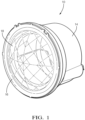
- Figs. 1 to 3 illustrate a non-limiting example of lighting assembly 10, e.g. a motor vehicle headlight.
- the lighting assembly 10 includes a light source or lamp 12, in this example a light emitting diode (LED) array.
- the LED lamp 12 is disposed within a lamp housing 14.
- a lens 16 encloses the lamp 12 within the lamp housing 14.
- the lens 16 has a resistive heating circuit 18 disposed on a surface of the lens 16 that is heated by an electric current flowing through the heating circuit 18 to heat the lens 16 to remove ice and/or snow from the lens 16.
- the lens 16 has a luminous transmittance greater than or equal to 0.9.
- the lighting assembly 10 also includes an electrical connector assembly 20 to provide an electrical current to the heating circuit 18 on the lens 16.
- the connector assembly 20 includes a pair of male post terminals 22 attached to the lens 16 and a pair of female receptacle terminal assemblies 24 configured to mate with the male post terminals 22.
- the lighting assembly 10 also includes several retaining rings to secure the lens 16 to the lamp housing 14 and the receptacle terminal assemblies 24 within the lamp housing 14.
- Figs 4A and 4B show the lens 16.
- the heating circuit 18 is arranged on the inner surface of the lens 16 and contains several radial elements and concentric elements.
- the heating circuit 18 may be formed on the lens 16 by a screen-printing process, a pad printing process or by depositing the circuit material on the lens 16 using a robotically controlled dispenser.
- the lens 16 may be formed of a glass or polymeric material.
- the post terminals 22 are attached to connection pads in the heating circuit 18.
- the post terminals 22 may be attached to the heating circuit 18 using a low temperature solder.
- the post terminals 22 may be attached to the heating circuit 18 using an electrically conducive adhesive, spin welding, or other materials and processes suitable for connecting a metal terminal to a circuit material disposed on glass or polymer.
- the lens 16 is characterized as having a round shape and a first post terminal 22 is arranged at a two o'clock position which is radially opposite a second post terminal 22 arranged at an eight o'clock position.
- Figs. 5 and 6 illustrate the connector assembly 20 as it is installed within the lighting assembly 10.
- the male post terminal 22 on the lens 16 is received within a female receptacle terminal 26 of the receptacle terminal assembly 24, thereby providing an electrical connection to the heating circuit 18 on the lens 16.
- Figs 7-12 illustrate the receptacle terminal assembly 24 which includes the receptacle terminal 26 that is formed from sheet metal, e.g. plated brass sheet stock.
- the receptacle terminal 26 has a ring-shaped connection portion 28 that defines a central aperture 30 in which the post terminal 22 is received along a longitudinal axis.
- the connection portion 28 defines a plurality of arcuate contact spring 32 surrounding the central aperture 30 that is configured to exert a contact force on the corresponding post terminal 22.
- the receptacle terminal 26 also includes an attachment portion 34 that is configured to attach the receptacle terminal 26 to an electrical wire 36.
- the attachment portion 34 is angularly offset relative to the connection portion 28.
- the attachment portion 34 is arranged at a 45-degree angle relative to the connection portion 28.
- the angled arrangement of the connection portion 28 allows a tighter fit between the lens and the housing, lessening the likelihood of gaps between the lens 16 and lamp housing 14 that could allow light leaks from the lighting assembly 10.
- the illustrated attachment portion 34 include a pair of crimp wings 38 that are crimped to the wire 36.
- Alternative embodiments of the attachment portion 34 may be envisioned that have a tubular section configured to be soldered to the wire 36 or a flat section to which the wire 36 may be sonically welded.
- the receptacle terminal assembly 24 also includes a terminal housing 40 that defines a first oval-shaped opening 42 and an oval-shaped cavity 44 in which the connection portion 28 is disposed.
- the connection portion 28 is sized, shaped, and arranged within the cavity 44 to be movable along a lateral axis Y that is perpendicular to the longitudinal axis Z.
- the oval-shaped cavity 44 provides lateral positional tolerance between the receptacle terminal 26 and the post terminal 22.
- the terminal housing 40 also defines a pair of slits 46 in the side walls 48 of the cavity 44 that allow the connection portion to also move along a transverse axis X that is perpendicular to both the lateral axis Y and the longitudinal axis Z. These slits 46 provide two degrees of freedom of movement for the connection portion 28, thereby providing additional positional tolerance between the receptacle terminal 26 and the post terminal 22.
- the receptacle terminal assembly 24 further includes a terminal housing cover 50 defining a second oval-shaped opening 52 attached to the terminal housing 40, thereby enclosing the connection portion 28 within the terminal housing 40. The first oval-shaped opening 42 is aligned with the second oval-shaped opening 52.
- a slot 54 is formed between the terminal housing 40 and the terminal housing cover 50 through which the attachment portion 34 extends.
- the terminal housing 40 and the terminal housing cover 50 are integrally formed having a living hinge 56 is disposed between the terminal housing 40 and the terminal housing cover 50 formed of a thin section of material between the terminal housing 40 and the terminal housing cover 50.
- Figs. 10-12 illustrate a process of assembling the receptacle terminal assembly 24. The receptacle terminal 26 is placed within the cavity 44 and then the hinge 56 is folded to attach the terminal housing cover 50 to the terminal housing 40. The terminal housing cover 50 is secured to the terminal housing 40 by a flexible latch feature 58 located opposite the hinge 56 on the terminal housing cover 50 which engages a ridge or ledge 60 on the terminal housing 40.
- Figs. 13A and 13B illustrate an example of the post terminal 22.
- the post terminal 22 is formed of an electrically conducive material, e.g. a copper-based material.
- the post terminal 22 is generally cylindrical with a rounded tip and a flat base, thereby giving the post terminal 22 a bullet shape.
- the post terminal 22 may be a solid piece formed by machining a billet or rod to the desired shape or casting a molten material to the desired shape.
- the post terminal 22 may be hollow and formed by rolling and stamping sheet metal.
- Fig. 14 shows the connector assembly 20 in a partially assembled position.
- the rounded end of the post terminal 22 contacts and spreads the contact springs 32 of the receptacle terminal 26 so that the contact springs 32 exert a contact force on the post terminal 22 to ensure a reliable and low resistance electrical connection between the post terminal 22 and the receptacle terminal 26.
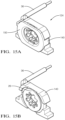
- Figs. 15A-16C illustrate an alternative design of the receptacle terminal assembly 124.
- the terminal housing 140 and the terminal housing cover 150 are two separate pieces and the terminal housing cover 150 is attached to the terminal housing 140 by two flexible latch features 158 that are located on opposite ends of the terminal housing cover 150.
- While the illustrated example is a motor vehicle headlight, other embodiments of the invention may be applied to motor vehicle taillights, side marker lights, and center high mounted stop lights. Other embodiments of the invention may be applied to non-automotive applications, such as building security lighting systems. Yet other embodiments for the invention may be applied to non-lighting applications, such as covers for a camera, a radio detection and ranging (RADAR) system, or a light imaging detection and ranging (LIDAR) system.
- RADAR radio detection and ranging
- LIDAR light imaging detection and ranging
- a lighting assembly 10 including an electrical connector assembly 20 for a heating circuit 18 on the lens 16 and a receptacle terminal assembly 24 for such a lighting assembly 10 is provided.
- the connector assembly 20 provide a simple push in electrical connection that may be made when coincidentally with installing the lens 16 to the lamp housing 14.
- the receptacle terminal 26 has two axes on movement within the receptacle terminal assembly 24 providing dimensional tolerance for the electrical connection.
- 'one or more' includes a function being performed by one element, a function being performed by more than one element, e.g., in a distributed fashion, several functions being performed by one element, several functions being performed by several elements, or any combination of the above.
- first, second, etc. are, in some instances, used herein to describe various elements, these elements should not be limited by these terms. These terms are only used to distinguish one element from another.
- a first contact could be termed a second contact, and, similarly, a second contact could be termed a first contact, without departing from the scope of the various described embodiments.
- the first contact and the second contact are both contacts, but they are not the same contact.
- the term “if' is, optionally, construed to mean “when” or “upon” or “in response to determining” or “in response to detecting,” depending on the context.
- the phrase “if it is determined” or “if [a stated condition or event] is detected” is, optionally, construed to mean “upon determining” or “in response to determining” or “upon detecting [the stated condition or event]” or “in response to detecting [the stated condition or event],” depending on the context.
Landscapes
- Engineering & Computer Science (AREA)
- General Engineering & Computer Science (AREA)
- Mechanical Engineering (AREA)
- Arrangement Of Elements, Cooling, Sealing, Or The Like Of Lighting Devices (AREA)
- Non-Portable Lighting Devices Or Systems Thereof (AREA)
Description
- The invention generally relates to a lighting assembly for a vehicle, particularly a lighting assembly having a device configured to heat a lens of the lighting assembly.
- Many vehicles have lighting systems that include some form of a head lamps, tail lamps, and side marking lamps. Lighting systems that use incandescent or HID bulbs, for example, generate sufficient waste heat so that snow and/or ice does not form or stick on lenses of the lighting system when the ambient temperature is below the freezing temperature of water. Snow or ice on the lens of the lighting system may reduce luminous transmittance of the lens, thereby degrading the performance of the lighting system. Some lighting systems, such as those using light emitting diode (LED) bulbs, do not generate sufficient waste to heat melt ice or snow on the lighting system lens due to their energy efficiency.
-
Publication US 2012/040553 A1 discloses a connector connected to a mating connector, which is fixed in a case of a motor, wherein the connector comprises: an outer housing attached to the case; a first inner housing accommodating a first terminal engaging to the mating connector, being accommodated in the outer housing movably in the engaging direction of the first terminal and in the intersectional direction of the engaging direction; a first inner connector engaging to the mating connector; a second inner housing accommodating a second terminal electrically connected to an electric circuit in the case and being fixed in the outer housing and a braided wire, and further including a connection portion connecting the first terminal and the second terminal and a packing attached to the first inner housing. PublicationJP H10 109587 A - Therefore, what is needed are improved systems and methods to sufficiently heat a lighting system lens to melt snow and ice to avoid reducing luminous transmittance of the lighting system lens.
- According to one embodiment of the invention, a lighting assembly is provided. The lighting assembly includes a lens covering a light source, a resistive circuit disposed on a surface of the lens, a post terminal connected to the resistive circuit, and a receptacle terminal having a connection portion defining an aperture configured to receive a corresponding plug terminal along a longitudinal axis and an attachment portion configured to attach the receptacle terminal to a wire. The lighting assembly also includes a terminal housing defining a first oval-shaped opening and an oval-shaped cavity in which the connection portion is disposed. The connection portion is sized, shaped, and arranged within the cavity to be movable along a lateral axis perpendicular to the longitudinal axis. The lighting assembly further includes a terminal housing cover defining a second oval-shaped opening aligned with the first oval-shaped opening, wherein the terminal housing and the terminal housing cover are integrally formed, wherein a hinge is disposed between the terminal housing and the terminal housing cover, wherein the terminal housing cover is attached to the terminal housing by a flexible latch feature located opposite the hinge on the terminal housing cover which engages a ridge on the terminal housing, and wherein the terminal housing cover is configured to enclose the cavity and secure the connection portion within the cavity.
- In an example embodiment having one or more features of the lighting assembly of the previous paragraph, a slot is formed between the terminal housing and the terminal housing cover through which the attachment portion extends.
- In an example embodiment having one or more features of the lighting assembly of the previous paragraph, the connection portion is characterized as having a circular ring shape.
- In an example embodiment having one or more features of the lighting assembly of the previous paragraph, the attachment portion is angularly offset relative to the connection portion.
- In an example embodiment having one or more features of the lighting assembly of the previous paragraph, the attachment portion is arranged at a 45-degree angle relative to the connection portion.
- In an example embodiment having one or more features of the lighting assembly of the previous paragraph, the connection portion defines a contact spring configured to exert a contact force on the post terminal.
- In an example embodiment having one or more features of the lighting assembly of the previous paragraph, the light source comprises a light emitting diode.
- In an example embodiment having one or more features of the lighting assembly of the previous paragraph, the post terminal has a cylindrical body and a rounded tip.
- In an example embodiment having one or more features of the lighting assembly of the previous paragraph, the connection portion defines a plurality of contact springs arranged about the aperture configured to exert a contact force on the post terminal.
- In an example embodiment having one or more features of the lighting assembly of the previous paragraph, the post terminal is soldered to the resistive circuit.
- In an example embodiment having one or more features of the lighting assembly of the previous paragraph, the lighting assembly further includes a pair of the receptacle terminals, a pair of the terminal housings, a pair of the terminal housing covers, and a pair of the post terminals, wherein the pair of the terminal housing covers are attached to the terminal housings by living hinges.
- According to another embodiment of the invention, a receptacle connector assembly for a lighting assembly is provided. The receptacle connector assembly includes a receptacle terminal having a ring-shaped connection portion defining a central aperture configured to receive a corresponding plug terminal along a longitudinal axis and an attachment portion configured to attach the receptacle terminal to a wire. The receptacle connector assembly also includes a terminal housing defining a first oval-shaped opening and an oval-shaped cavity in which the connection portion is disposed. The connection portion is sized, shaped, and arranged within the cavity to be movable along a lateral axis perpendicular to the longitudinal axis. The receptacle connector assembly further includes a terminal housing cover separate from the terminal housing and defining a second oval-shaped opening. The terminal housing cover is attached to the terminal housing by two flexible latch features that are located on opposite ends of the terminal housing cover, thereby enclosing and securing the connection portion within the cavity. The first oval-shaped opening is aligned with the second oval-shaped opening.
- In an example embodiment having one or more features of the receptacle connector assembly of the previous paragraph, a slot is formed between the terminal housing and the terminal housing cover through which the attachment portion extends.
- In an example embodiment having one or more features of the receptacle connector assembly of the previous paragraph, the attachment portion is angularly offset relative to the connection portion.
- In an example embodiment having one or more features of the receptacle connector assembly of the previous paragraph, the attachment portion is arranged at a 45-degree angle relative to the connection portion.
- In an example embodiment having one or more features of the receptacle connector assembly of the previous paragraph, the connection portion defines a plurality of contact springs surrounding the central aperture configured to exert a contact force on the corresponding plug terminal.
- The present invention will now be described, by way of example with reference to the accompanying drawings, in which:
-
Fig. 1 is a perspective view of a lighting assembly according to a first embodiment of the invention; -
Fig. 2 is an exploded view of the lighting assembly ofFig. 1 according to the first embodiment of the invention; -
Fig. 3 is a front view of the lighting assembly ofFig. 1 according to the first embodiment of the invention; -
Fig. 4A is a front view of a lens of the lighting assembly ofFig. 1 according to the first embodiment of the invention; -
Fig. 4B is a side view of the lens ofFig. 4A according to the first embodiment of the invention; -
Fig. 5 is an isolated top view of an electrical connector assembly of the lighting assembly ofFig. 1 according to the first embodiment of the invention; -
Fig. 6 is cross section view of the electrical connector assembly ofFig. 5 according to the first embodiment of the invention; -
Fig. 7 is a side view of a female receptacle terminal assembly of the electrical connector assembly ofFig. 5 according to the first embodiment of the invention; -
Fig. 8 is a top view of the female receptacle terminal assembly ofFig. 7 according to the first embodiment of the invention; -
Fig. 9 is a bottom view of the female receptacle terminal assembly ofFig. 7 according to the first embodiment of the invention; -
Fig. 10 is an exploded view of the female receptacle terminal assembly ofFig. 7 according to the first embodiment of the invention; -
Fig. 11 is a perspective view of the female receptacle terminal assembly ofFig. 7 in a partially assembled condition according to the first embodiment of the invention; -
Fig. 12 is a perspective view of the female receptacle terminal assembly ofFig. 7 in a fully assembled condition according to the first embodiment of the invention; -
Fig. 13A is a top view of a male post terminal of the electrical connector assembly ofFig. 5 according to the first embodiment of the invention; -
Fig. 13B is a side view of the post plug terminal of Fig. 7A according to the first embodiment of the invention; -
Fig. 14 is a side view of the electrical connector assembly ofFig. 5 in a partially assembled condition according to the first embodiment of the invention; -
Fig. 15A is a perspective view of a female receptacle terminal assembly in a fully assembled condition according to a second embodiment of the invention; -
Fig. 15B is a perspective view of the female receptacle terminal assembly ofFig. 15A in a partially assembled condition according to the second embodiment of the invention; -
Fig. 16A is a side view of a terminal housing cover of the female receptacle terminal assembly ofFig. 15A according to the second embodiment of the invention; -
Fig. 16B is a top view of the terminal housing cover ofFig. 16A according to the second embodiment of the invention; and -
Fig. 16C is an end view of the terminal housing cover ofFig. 16A according to the second embodiment of the invention. - In the preceding drawings and in the following description, similar elements share the last two reference numbers.
- Reference will now be made in detail to embodiments, examples of which are illustrated in the accompanying drawings. In the following detailed description, numerous specific details are set forth to provide a thorough understanding of the various described embodiments. However, it will be apparent to one of ordinary skill in the art that the various described embodiments may be practiced without these specific details. In other instances, well-known methods, procedures, components, circuits, and networks have not been described in detail so as not to unnecessarily obscure aspects of the embodiments.
-
Figs. 1 to 3 illustrate a non-limiting example oflighting assembly 10, e.g. a motor vehicle headlight. Thelighting assembly 10 includes a light source orlamp 12, in this example a light emitting diode (LED) array. TheLED lamp 12 is disposed within alamp housing 14. As best shown inFig. 1 , alens 16 encloses thelamp 12 within thelamp housing 14. As best shown inFig. 3 , thelens 16 has aresistive heating circuit 18 disposed on a surface of thelens 16 that is heated by an electric current flowing through theheating circuit 18 to heat thelens 16 to remove ice and/or snow from thelens 16. In the illustrated example of a headlight, thelens 16 has a luminous transmittance greater than or equal to 0.9. Thelighting assembly 10 also includes an electrical connector assembly 20 to provide an electrical current to theheating circuit 18 on thelens 16. The connector assembly 20 includes a pair ofmale post terminals 22 attached to thelens 16 and a pair of femalereceptacle terminal assemblies 24 configured to mate with themale post terminals 22. Thelighting assembly 10 also includes several retaining rings to secure thelens 16 to thelamp housing 14 and thereceptacle terminal assemblies 24 within thelamp housing 14. -
Figs 4A and 4B show thelens 16. Theheating circuit 18 is arranged on the inner surface of thelens 16 and contains several radial elements and concentric elements. Theheating circuit 18 may be formed on thelens 16 by a screen-printing process, a pad printing process or by depositing the circuit material on thelens 16 using a robotically controlled dispenser. Thelens 16 may be formed of a glass or polymeric material. Thepost terminals 22 are attached to connection pads in theheating circuit 18. Thepost terminals 22 may be attached to theheating circuit 18 using a low temperature solder. Alternatively, thepost terminals 22 may be attached to theheating circuit 18 using an electrically conducive adhesive, spin welding, or other materials and processes suitable for connecting a metal terminal to a circuit material disposed on glass or polymer. In theexample lighting assembly 10 illustrated inFigs. 1-3 , thelens 16 is characterized as having a round shape and afirst post terminal 22 is arranged at a two o'clock position which is radially opposite asecond post terminal 22 arranged at an eight o'clock position. -
Figs. 5 and 6 illustrate the connector assembly 20 as it is installed within thelighting assembly 10. Themale post terminal 22 on thelens 16 is received within afemale receptacle terminal 26 of thereceptacle terminal assembly 24, thereby providing an electrical connection to theheating circuit 18 on thelens 16. -
Figs 7-12 illustrate thereceptacle terminal assembly 24 which includes thereceptacle terminal 26 that is formed from sheet metal, e.g. plated brass sheet stock. Thereceptacle terminal 26 has a ring-shapedconnection portion 28 that defines acentral aperture 30 in which thepost terminal 22 is received along a longitudinal axis. Theconnection portion 28 defines a plurality ofarcuate contact spring 32 surrounding thecentral aperture 30 that is configured to exert a contact force on thecorresponding post terminal 22. Thereceptacle terminal 26 also includes anattachment portion 34 that is configured to attach thereceptacle terminal 26 to anelectrical wire 36. Theattachment portion 34 is angularly offset relative to theconnection portion 28. In the illustrated example, theattachment portion 34 is arranged at a 45-degree angle relative to theconnection portion 28. The angled arrangement of theconnection portion 28 allows a tighter fit between the lens and the housing, lessening the likelihood of gaps between thelens 16 andlamp housing 14 that could allow light leaks from thelighting assembly 10. - The illustrated
attachment portion 34 include a pair of crimp wings 38 that are crimped to thewire 36. Alternative embodiments of theattachment portion 34 may be envisioned that have a tubular section configured to be soldered to thewire 36 or a flat section to which thewire 36 may be sonically welded. Thereceptacle terminal assembly 24 also includes aterminal housing 40 that defines a first oval-shapedopening 42 and an oval-shapedcavity 44 in which theconnection portion 28 is disposed. Theconnection portion 28 is sized, shaped, and arranged within thecavity 44 to be movable along a lateral axis Y that is perpendicular to the longitudinal axis Z. The oval-shapedcavity 44 provides lateral positional tolerance between thereceptacle terminal 26 and thepost terminal 22. Theterminal housing 40 also defines a pair ofslits 46 in theside walls 48 of thecavity 44 that allow the connection portion to also move along a transverse axis X that is perpendicular to both the lateral axis Y and the longitudinal axis Z. Theseslits 46 provide two degrees of freedom of movement for theconnection portion 28, thereby providing additional positional tolerance between thereceptacle terminal 26 and thepost terminal 22. Thereceptacle terminal assembly 24 further includes aterminal housing cover 50 defining a second oval-shapedopening 52 attached to theterminal housing 40, thereby enclosing theconnection portion 28 within theterminal housing 40. The first oval-shapedopening 42 is aligned with the second oval-shapedopening 52. Aslot 54 is formed between theterminal housing 40 and theterminal housing cover 50 through which theattachment portion 34 extends. In example illustrated inFigs. 7-12 , theterminal housing 40 and theterminal housing cover 50 are integrally formed having a livinghinge 56 is disposed between theterminal housing 40 and theterminal housing cover 50 formed of a thin section of material between theterminal housing 40 and theterminal housing cover 50.Figs. 10-12 illustrate a process of assembling thereceptacle terminal assembly 24. Thereceptacle terminal 26 is placed within thecavity 44 and then thehinge 56 is folded to attach theterminal housing cover 50 to theterminal housing 40. Theterminal housing cover 50 is secured to theterminal housing 40 by aflexible latch feature 58 located opposite thehinge 56 on theterminal housing cover 50 which engages a ridge orledge 60 on theterminal housing 40. -
Figs. 13A and 13B illustrate an example of thepost terminal 22. Thepost terminal 22 is formed of an electrically conducive material, e.g. a copper-based material. Thepost terminal 22 is generally cylindrical with a rounded tip and a flat base, thereby giving the post terminal 22 a bullet shape. Thepost terminal 22 may be a solid piece formed by machining a billet or rod to the desired shape or casting a molten material to the desired shape. Alternatively, thepost terminal 22 may be hollow and formed by rolling and stamping sheet metal. -
Fig. 14 shows the connector assembly 20 in a partially assembled position. The rounded end of thepost terminal 22 contacts and spreads the contact springs 32 of thereceptacle terminal 26 so that the contact springs 32 exert a contact force on thepost terminal 22 to ensure a reliable and low resistance electrical connection between thepost terminal 22 and thereceptacle terminal 26. -
Figs. 15A-16C illustrate an alternative design of thereceptacle terminal assembly 124. In this design, theterminal housing 140 and theterminal housing cover 150 are two separate pieces and theterminal housing cover 150 is attached to theterminal housing 140 by two flexible latch features 158 that are located on opposite ends of theterminal housing cover 150. - While the illustrated example is a motor vehicle headlight, other embodiments of the invention may be applied to motor vehicle taillights, side marker lights, and center high mounted stop lights. Other embodiments of the invention may be applied to non-automotive applications, such as building security lighting systems. Yet other embodiments for the invention may be applied to non-lighting applications, such as covers for a camera, a radio detection and ranging (RADAR) system, or a light imaging detection and ranging (LIDAR) system.
- Accordingly, a
lighting assembly 10 including an electrical connector assembly 20 for aheating circuit 18 on thelens 16 and areceptacle terminal assembly 24 for such alighting assembly 10 is provided. The connector assembly 20 provide a simple push in electrical connection that may be made when coincidentally with installing thelens 16 to thelamp housing 14. Thereceptacle terminal 26 has two axes on movement within thereceptacle terminal assembly 24 providing dimensional tolerance for the electrical connection. - While this invention has been described in terms of the preferred embodiments thereof, it is not intended to be so limited, but rather only to the extent set forth in the claims that follow. For example, the above-described embodiments (and/or aspects thereof) may be used in combination with each other. In addition, many modifications may be made to configure a situation or material to the teachings of the invention without departing from its scope. Dimensions, types of materials, orientations of the various components, and the number and positions of the various components described herein are intended to define parameters of certain embodiments and are by no means limiting and are merely prototypical embodiments.
- As used herein, 'one or more' includes a function being performed by one element, a function being performed by more than one element, e.g., in a distributed fashion, several functions being performed by one element, several functions being performed by several elements, or any combination of the above.
- It will also be understood that, although the terms first, second, etc. are, in some instances, used herein to describe various elements, these elements should not be limited by these terms. These terms are only used to distinguish one element from another. For example, a first contact could be termed a second contact, and, similarly, a second contact could be termed a first contact, without departing from the scope of the various described embodiments. The first contact and the second contact are both contacts, but they are not the same contact.
- The terminology used in the description of the various described embodiments herein is for the purpose of describing particular embodiments only and is not intended to be limiting. As used in the description of the various described embodiments and the appended claims, the singular forms "a", "an" and "the" are intended to include the plural forms as well, unless the context clearly indicates otherwise. It will also be understood that the term "and/or" as used herein refers to and encompasses all possible combinations of one or more of the associated listed items. It will be further understood that the terms "includes," "including," "comprises," and/or "comprising," when used in this specification, specify the presence of stated features, integers, steps, operations, elements, and/or components, but do not preclude the presence or addition of one or more other features, integers, steps, operations, elements, components, and/or groups thereof.
- As used herein, the term "if' is, optionally, construed to mean "when" or "upon" or "in response to determining" or "in response to detecting," depending on the context. Similarly, the phrase "if it is determined" or "if [a stated condition or event] is detected" is, optionally, construed to mean "upon determining" or "in response to determining" or "upon detecting [the stated condition or event]" or "in response to detecting [the stated condition or event]," depending on the context.
Claims (12)
- A lighting assembly (10), comprising:a lens (16) covering a light source (12);a resistive circuit disposed on a surface of the lens (16);a post terminal (22) connected to the resistive circuit;a receptacle terminal (26) having a connection portion (28) defining an aperture configured to receive the post terminal (22) along a longitudinal axis (X) and an attachment portion (34) configured to attach the receptacle terminal (26) to a wire (36);characterized bya terminal housing (40) defining a first oval-shaped opening (42) and an oval-shaped cavity (44) in which the connection portion (28) is disposed, wherein the connection portion (28) is sized, shaped, and arranged within the cavity (44) to be movable along a lateral axis (Y) perpendicular to the longitudinal axis (X);a terminal housing cover (50) defining a second oval-shaped opening (52) aligned with the first oval-shaped opening (42), wherein the terminal housing (40) and the terminal housing cover (50) are integrally formed, wherein a hinge (56) is disposed between the terminal housing (40) and the terminal housing cover (50), wherein the terminal housing cover (50) is attached to the terminal housing (40) by a flexible latch feature (58) located opposite the hinge (56) on the terminal housing cover (50) which engages a ridge (60) on the terminal housing (40), and wherein the terminal housing cover (50) is configured to enclose the cavity (44) and secure the connection portion (28) within the cavity (44).
- The lighting assembly (10) according to claim 1, wherein a slot (54) is formed between the terminal housing (40) and the terminal housing cover (50) through which the attachment portion (34) extends.
- The lighting assembly (10) according to claim 1 or 2, wherein the connection portion (28) is characterized as having a circular ring shape, wherein the attachment portion (34) is angularly offset at a 45 degree angle relative to the connection portion (28).
- The lighting assembly (10) according to any one of the preceding claims,
wherein the connection portion (28) defines a contact spring (32) configured to exert a contact force on the post terminal (22). - The lighting assembly (10) according to any one of the preceding claims,
wherein the light source (12) comprises a light emitting diode. - The lighting assembly (10) according to any one of the preceding claims,wherein the post terminal (22) has a cylindrical body and a rounded tip andwherein the connection portion (28) defines a plurality of contact springs (32) arranged about the aperture configured to exert a contact force on the post terminal (22).
- The lighting assembly (10) according to any one of the preceding claims,
wherein the post terminal (22) is soldered to the resistive circuit. - The lighting assembly (10) according to any one of the preceding claims, further comprising:a pair of the receptacle terminals (26);a pair of the terminal housings (40);a pair of the terminal housing covers (50); anda pair of the post terminals (22),wherein the pair of the terminal housing covers (50) are attached to the terminal housings (40) by living hinges (56).
- A receptacle connector assembly (124) for a lighting assembly (10), comprising:a receptacle terminal (26) having a ring-shaped connection portion (28) defining a central aperture (30) configured to receive a corresponding plug terminal (22) along a longitudinal axis (X) and an attachment portion (34) configured to attach the receptacle terminal (26) to a wire (36),characterized bya terminal housing (140) defining a first oval-shaped opening (42) and an oval-shaped cavity (44) in which the connection portion (28) is disposed, wherein the connection portion (28) is sized, shaped, and arranged within the cavity (44) to be movable along a lateral axis (Y) perpendicular to the longitudinal axis (X),a terminal housing cover (150) separate from the terminal housing (140) and defining a second oval-shaped opening (52), wherein the terminal housing cover (150) is attached to the terminal housing (140) by two flexible latch features (158) that are located on opposite ends of the terminal housing cover (150), thereby enclosing and securing the connection portion (28) within the cavity (44), wherein the first oval-shaped opening (42) is aligned with the second oval-shaped opening (52).
- The receptacle connector assembly (124) according to claim 9, wherein a slot (54) is formed between the terminal housing (140) and the terminal housing cover (150) through which the attachment portion (34) extends.
- The receptacle connector assembly (124) according to claim 9 or 10, wherein the attachment portion (34) is angularly offset at a 45-degree angle relative to the connection portion (28).
- The receptacle connector assembly (24, 124) according to any one of claims 9 to 11, wherein the connection portion (28) defines a plurality of contact springs (32) surrounding the central aperture (30) configured to exert a contact force on the corresponding plug terminal (22).
Priority Applications (1)
| Application Number | Priority Date | Filing Date | Title |
|---|---|---|---|
| EP24214449.1A EP4489227A3 (en) | 2019-09-05 | 2020-09-02 | Vehicle lighting assembly with lens heating device and receptacle connector assembly for same |
Applications Claiming Priority (1)
| Application Number | Priority Date | Filing Date | Title |
|---|---|---|---|
| US16/561,327 US11236884B2 (en) | 2019-09-05 | 2019-09-05 | Vehicle lighting assembly with lens heating device and receptacle connector assembly for same |
Related Child Applications (1)
| Application Number | Title | Priority Date | Filing Date |
|---|---|---|---|
| EP24214449.1A Division EP4489227A3 (en) | 2019-09-05 | 2020-09-02 | Vehicle lighting assembly with lens heating device and receptacle connector assembly for same |
Publications (2)
| Publication Number | Publication Date |
|---|---|
| EP3789662A1 EP3789662A1 (en) | 2021-03-10 |
| EP3789662B1 true EP3789662B1 (en) | 2024-12-18 |
Family
ID=72355751
Family Applications (2)
| Application Number | Title | Priority Date | Filing Date |
|---|---|---|---|
| EP20194032.7A Active EP3789662B1 (en) | 2019-09-05 | 2020-09-02 | Vehicle lighting assembly with lens heating device and receptacle connector assembly for same |
| EP24214449.1A Pending EP4489227A3 (en) | 2019-09-05 | 2020-09-02 | Vehicle lighting assembly with lens heating device and receptacle connector assembly for same |
Family Applications After (1)
| Application Number | Title | Priority Date | Filing Date |
|---|---|---|---|
| EP24214449.1A Pending EP4489227A3 (en) | 2019-09-05 | 2020-09-02 | Vehicle lighting assembly with lens heating device and receptacle connector assembly for same |
Country Status (3)
| Country | Link |
|---|---|
| US (3) | US11236884B2 (en) |
| EP (2) | EP3789662B1 (en) |
| CN (2) | CN112443815B (en) |
Families Citing this family (2)
| Publication number | Priority date | Publication date | Assignee | Title |
|---|---|---|---|---|
| US11236884B2 (en) * | 2019-09-05 | 2022-02-01 | Aptiv Limited Technologies | Vehicle lighting assembly with lens heating device and receptacle connector assembly for same |
| JP7522968B2 (en) * | 2021-09-24 | 2024-07-26 | 豊田合成株式会社 | Vehicle exterior parts |
Family Cites Families (39)
| Publication number | Priority date | Publication date | Assignee | Title |
|---|---|---|---|---|
| US3289200A (en) * | 1965-03-02 | 1966-11-29 | Amp Inc | Housing for indicating lamp or other electrical components |
| JP3636393B2 (en) | 1995-10-31 | 2005-04-06 | ミネソタ マイニング アンド マニュファクチャリング カンパニー | Branch connector device |
| JPH10109587A (en) | 1996-10-03 | 1998-04-28 | Koito Mfg Co Ltd | Vehicle lighting |
| DE19860588C2 (en) * | 1998-12-29 | 2001-03-01 | Schnippering Hugo Gmbh Co Kg | Lamp holder made of insulating material for H 7 lamps |
| FR2796764B1 (en) | 1999-07-21 | 2001-08-17 | Renault | ELECTRICAL CONNECTION DEVICE IN PARTICULAR FOR GLAZING |
| US6520812B1 (en) | 2000-08-30 | 2003-02-18 | Antaya Technologies Corporation | Connector terminal with resilient contacts |
| JP2003136956A (en) | 2001-11-07 | 2003-05-14 | Asahi Glass Co Ltd | Window structure for automobile, window material for automobile, and method for attaching window material for automobile to vehicle body |
| US6638075B2 (en) * | 2002-02-27 | 2003-10-28 | James R. Spaulding | Electrical connection to windshield/backglass |
| WO2005047714A1 (en) * | 2003-11-17 | 2005-05-26 | Telezygology Inc | Fasteners and other assemblies |
| JP2006032137A (en) | 2004-07-16 | 2006-02-02 | Koito Mfg Co Ltd | VEHICLE LIGHT AND METHOD FOR PRODUCING VEHICLE LIGHT |
| JP2006082479A (en) * | 2004-09-17 | 2006-03-30 | Koito Mfg Co Ltd | Manufacturing method of vehicular lamp |
| JP2007220433A (en) * | 2006-02-15 | 2007-08-30 | Yazaki Corp | Lamp unit |
| DE102006060516A1 (en) | 2006-12-21 | 2008-06-26 | Daimler Ag | Push button connector arrangement for electrical connection between electrically conducting element embedded in automobile glass pane, particularly antenna and vehicle body side attachment, has plug contact element |
| WO2009125854A1 (en) * | 2008-04-11 | 2009-10-15 | 富士フイルム株式会社 | Front cover for vehicle lighting fixture, method of manufacturing the front cover, and electric heating structure |
| JP5430921B2 (en) * | 2008-05-16 | 2014-03-05 | 富士フイルム株式会社 | Conductive film and transparent heating element |
| JP5409094B2 (en) * | 2008-07-17 | 2014-02-05 | 富士フイルム株式会社 | Curved molded body and manufacturing method thereof, front cover for vehicle lamp and manufacturing method thereof |
| JP5399804B2 (en) * | 2009-08-03 | 2014-01-29 | 矢崎総業株式会社 | connector |
| US8342867B2 (en) * | 2009-12-01 | 2013-01-01 | Raytheon Company | Free floating connector engagement and retention system and method for establishing a temporary electrical connection |
| US9709238B2 (en) | 2011-02-09 | 2017-07-18 | Truck-Lite Co., Llc | Modular headlamp assembly with a heating element for removing water based contamination |
| KR101600216B1 (en) | 2011-12-20 | 2016-03-04 | 쌩-고벵 글래스 프랑스 | Heatable luminaire cover |
| JP5801705B2 (en) * | 2011-12-22 | 2015-10-28 | 矢崎総業株式会社 | Waterproof connector connection structure |
| JP5860312B2 (en) * | 2012-03-09 | 2016-02-16 | 象印マホービン株式会社 | Electric heater |
| CN102694298B (en) * | 2012-05-31 | 2014-07-09 | 深圳市凯信光电有限公司 | LED lamp strip, connector and component of LED lamp strip |
| EP2893255B1 (en) * | 2012-09-07 | 2017-02-01 | Philips Lighting Holding B.V. | Lighting device with integrated lens heat sink |
| JP6024986B2 (en) | 2013-05-30 | 2016-11-16 | 株式会社オートネットワーク技術研究所 | Terminal block |
| US9623790B2 (en) | 2013-08-21 | 2017-04-18 | George A. Van Straten | Light retainer assembly and heated light assembly |
| US10046692B2 (en) | 2014-08-14 | 2018-08-14 | George A. Van Straten | Heated light enclosure having an adaptable heating system |
| CN107923597B (en) * | 2015-06-15 | 2020-06-16 | J.W.扬声器股份有限公司 | Lens heating system and method for LED lighting system |
| US11019689B2 (en) * | 2015-06-15 | 2021-05-25 | J.W. Speaker Corporation | Lens heating systems and methods for an LED lighting system |
| JP6208195B2 (en) | 2015-10-20 | 2017-10-04 | 第一精工株式会社 | Terminal fitting and connector using the same |
| FR3050899A1 (en) | 2016-04-29 | 2017-11-03 | Valeo Vision | AUTOMOTIVE PROJECTOR ICE WITH OVERMOLDED METAL ELECTRODES |
| FR3060711A1 (en) | 2016-12-20 | 2018-06-22 | Valeo Vision | AUTOMOTIVE PROJECTOR ICE WITH OVERMOULATED THERMOPLASTIC ELECTRODES |
| KR102705245B1 (en) * | 2017-02-13 | 2024-09-11 | 엘지이노텍 주식회사 | Camera module and vehicle |
| US10374330B1 (en) * | 2018-05-17 | 2019-08-06 | Agc Automotive Americas R&D, Inc. | Window assembly with solderless electrical connector |
| US11066047B1 (en) * | 2018-10-31 | 2021-07-20 | Keith Keller | LED tail light heater cover |
| US11236884B2 (en) * | 2019-09-05 | 2022-02-01 | Aptiv Limited Technologies | Vehicle lighting assembly with lens heating device and receptacle connector assembly for same |
| JP7226260B2 (en) * | 2019-11-13 | 2023-02-21 | 株式会社オートネットワーク技術研究所 | connector device |
| TWM592943U (en) * | 2019-11-14 | 2020-04-01 | 敏翔股份有限公司 | Car light with heating function |
| EP4123357A1 (en) * | 2021-07-23 | 2023-01-25 | Ficosa Adas, S.L.U. | Lens assembly, camera module having a lens assembly for motor vehicles, and a method for making a lens assembly |
-
2019
- 2019-09-05 US US16/561,327 patent/US11236884B2/en active Active
-
2020
- 2020-08-28 CN CN202010884856.5A patent/CN112443815B/en active Active
- 2020-08-28 CN CN202310616359.0A patent/CN116518329A/en active Pending
- 2020-09-02 EP EP20194032.7A patent/EP3789662B1/en active Active
- 2020-09-02 EP EP24214449.1A patent/EP4489227A3/en active Pending
-
2021
- 2021-12-21 US US17/557,333 patent/US11898718B2/en active Active
-
2023
- 2023-12-27 US US18/397,152 patent/US20240125453A1/en active Pending
Also Published As
| Publication number | Publication date |
|---|---|
| EP4489227A2 (en) | 2025-01-08 |
| CN112443815B (en) | 2023-05-23 |
| US11236884B2 (en) | 2022-02-01 |
| EP3789662A1 (en) | 2021-03-10 |
| US20240125453A1 (en) | 2024-04-18 |
| US20210071841A1 (en) | 2021-03-11 |
| US11898718B2 (en) | 2024-02-13 |
| EP4489227A3 (en) | 2025-03-19 |
| CN116518329A (en) | 2023-08-01 |
| US20220112999A1 (en) | 2022-04-14 |
| CN112443815A (en) | 2021-03-05 |
Similar Documents
| Publication | Publication Date | Title |
|---|---|---|
| US20240125453A1 (en) | Receptacle connector assembly | |
| CN110382946B (en) | LED lights | |
| JP5409893B2 (en) | High pressure discharge lamp | |
| EP1341267A3 (en) | Hyperboloid electrical contact | |
| US5010272A (en) | Cementless electric lamp - base combination | |
| KR20020040880A (en) | Headlight bulb | |
| US5944545A (en) | Single pin coaxial initiator, retainer and connector and method of operation | |
| JP2016512385A (en) | Self-arranged light source module | |
| US11397299B2 (en) | Light module for illuminating an outer component of a vehicle, and process for manufacturing such light module | |
| US5952773A (en) | Capped electric lamp | |
| EP3513116A1 (en) | Light module for illuminating an outer component of a vehicle, and process for manufacturing such light module | |
| US6971904B2 (en) | Light bulb socket for motor vehicle lamps | |
| WO2002090142A2 (en) | Integrated lamp holder, reflector, and plug terminal arrangement for automotive lighting applications | |
| EP1690282B1 (en) | Lamp socket with improved heat conduction | |
| JP4540277B2 (en) | Lamp with cap | |
| EP3826117A1 (en) | Replacement contact-tip for an electrical contact of a connector | |
| EP3279558B1 (en) | Luminaire | |
| US20040036417A1 (en) | Lamp housing with integral circuit grid | |
| CN101506575A (en) | Fastening system and lamp having a fastening system | |
| WO2008129445A1 (en) | Lamp | |
| WO2007050710A2 (en) | Molded lamp socket | |
| GB2307112A (en) | Insulated lampholder pin | |
| WO2010086765A1 (en) | Burner and method for assembling a lamp | |
| JPH1166902A (en) | Discharge type lamp device for vehicles |
Legal Events
| Date | Code | Title | Description |
|---|---|---|---|
| PUAI | Public reference made under article 153(3) epc to a published international application that has entered the european phase |
Free format text: ORIGINAL CODE: 0009012 |
|
| STAA | Information on the status of an ep patent application or granted ep patent |
Free format text: STATUS: THE APPLICATION HAS BEEN PUBLISHED |
|
| AK | Designated contracting states |
Kind code of ref document: A1 Designated state(s): AL AT BE BG CH CY CZ DE DK EE ES FI FR GB GR HR HU IE IS IT LI LT LU LV MC MK MT NL NO PL PT RO RS SE SI SK SM TR |
|
| AX | Request for extension of the european patent |
Extension state: BA ME |
|
| STAA | Information on the status of an ep patent application or granted ep patent |
Free format text: STATUS: REQUEST FOR EXAMINATION WAS MADE |
|
| 17P | Request for examination filed |
Effective date: 20210909 |
|
| RBV | Designated contracting states (corrected) |
Designated state(s): AL AT BE BG CH CY CZ DE DK EE ES FI FR GB GR HR HU IE IS IT LI LT LU LV MC MK MT NL NO PL PT RO RS SE SI SK SM TR |
|
| STAA | Information on the status of an ep patent application or granted ep patent |
Free format text: STATUS: EXAMINATION IS IN PROGRESS |
|
| 17Q | First examination report despatched |
Effective date: 20221006 |
|
| RAP3 | Party data changed (applicant data changed or rights of an application transferred) |
Owner name: APTIV TECHNOLOGIES LIMITED |
|
| RAP1 | Party data changed (applicant data changed or rights of an application transferred) |
Owner name: APTIV TECHNOLOGIES AG |
|
| GRAP | Despatch of communication of intention to grant a patent |
Free format text: ORIGINAL CODE: EPIDOSNIGR1 |
|
| STAA | Information on the status of an ep patent application or granted ep patent |
Free format text: STATUS: GRANT OF PATENT IS INTENDED |
|
| RAP3 | Party data changed (applicant data changed or rights of an application transferred) |
Owner name: APTIV TECHNOLOGIES AG |
|
| INTG | Intention to grant announced |
Effective date: 20240920 |
|
| GRAS | Grant fee paid |
Free format text: ORIGINAL CODE: EPIDOSNIGR3 |
|
| GRAA | (expected) grant |
Free format text: ORIGINAL CODE: 0009210 |
|
| STAA | Information on the status of an ep patent application or granted ep patent |
Free format text: STATUS: THE PATENT HAS BEEN GRANTED |
|
| P01 | Opt-out of the competence of the unified patent court (upc) registered |
Free format text: CASE NUMBER: APP_55772/2024 Effective date: 20241011 |
|
| AK | Designated contracting states |
Kind code of ref document: B1 Designated state(s): AL AT BE BG CH CY CZ DE DK EE ES FI FR GB GR HR HU IE IS IT LI LT LU LV MC MK MT NL NO PL PT RO RS SE SI SK SM TR |
|
| REG | Reference to a national code |
Ref country code: CH Ref legal event code: EP |
|
| REG | Reference to a national code |
Ref country code: DE Ref legal event code: R096 Ref document number: 602020043252 Country of ref document: DE |
|
| REG | Reference to a national code |
Ref country code: IE Ref legal event code: FG4D |
|
| REG | Reference to a national code |
Ref country code: LT Ref legal event code: MG9D |
|
| PG25 | Lapsed in a contracting state [announced via postgrant information from national office to epo] |
Ref country code: HR Free format text: LAPSE BECAUSE OF FAILURE TO SUBMIT A TRANSLATION OF THE DESCRIPTION OR TO PAY THE FEE WITHIN THE PRESCRIBED TIME-LIMIT Effective date: 20241218 |
|
| PG25 | Lapsed in a contracting state [announced via postgrant information from national office to epo] |
Ref country code: FI Free format text: LAPSE BECAUSE OF FAILURE TO SUBMIT A TRANSLATION OF THE DESCRIPTION OR TO PAY THE FEE WITHIN THE PRESCRIBED TIME-LIMIT Effective date: 20241218 |
|
| PG25 | Lapsed in a contracting state [announced via postgrant information from national office to epo] |
Ref country code: BG Free format text: LAPSE BECAUSE OF FAILURE TO SUBMIT A TRANSLATION OF THE DESCRIPTION OR TO PAY THE FEE WITHIN THE PRESCRIBED TIME-LIMIT Effective date: 20241218 |
|
| PG25 | Lapsed in a contracting state [announced via postgrant information from national office to epo] |
Ref country code: NO Free format text: LAPSE BECAUSE OF FAILURE TO SUBMIT A TRANSLATION OF THE DESCRIPTION OR TO PAY THE FEE WITHIN THE PRESCRIBED TIME-LIMIT Effective date: 20250318 |
|
| REG | Reference to a national code |
Ref country code: NL Ref legal event code: MP Effective date: 20241218 |
|
| PG25 | Lapsed in a contracting state [announced via postgrant information from national office to epo] |
Ref country code: LV Free format text: LAPSE BECAUSE OF FAILURE TO SUBMIT A TRANSLATION OF THE DESCRIPTION OR TO PAY THE FEE WITHIN THE PRESCRIBED TIME-LIMIT Effective date: 20241218 Ref country code: GR Free format text: LAPSE BECAUSE OF FAILURE TO SUBMIT A TRANSLATION OF THE DESCRIPTION OR TO PAY THE FEE WITHIN THE PRESCRIBED TIME-LIMIT Effective date: 20250319 |
|
| PG25 | Lapsed in a contracting state [announced via postgrant information from national office to epo] |
Ref country code: RS Free format text: LAPSE BECAUSE OF FAILURE TO SUBMIT A TRANSLATION OF THE DESCRIPTION OR TO PAY THE FEE WITHIN THE PRESCRIBED TIME-LIMIT Effective date: 20250318 |
|
| PG25 | Lapsed in a contracting state [announced via postgrant information from national office to epo] |
Ref country code: NL Free format text: LAPSE BECAUSE OF FAILURE TO SUBMIT A TRANSLATION OF THE DESCRIPTION OR TO PAY THE FEE WITHIN THE PRESCRIBED TIME-LIMIT Effective date: 20241218 |
|
| REG | Reference to a national code |
Ref country code: AT Ref legal event code: MK05 Ref document number: 1752488 Country of ref document: AT Kind code of ref document: T Effective date: 20241218 |
|
| PG25 | Lapsed in a contracting state [announced via postgrant information from national office to epo] |
Ref country code: SM Free format text: LAPSE BECAUSE OF FAILURE TO SUBMIT A TRANSLATION OF THE DESCRIPTION OR TO PAY THE FEE WITHIN THE PRESCRIBED TIME-LIMIT Effective date: 20241218 |
|
| PG25 | Lapsed in a contracting state [announced via postgrant information from national office to epo] |
Ref country code: PL Free format text: LAPSE BECAUSE OF FAILURE TO SUBMIT A TRANSLATION OF THE DESCRIPTION OR TO PAY THE FEE WITHIN THE PRESCRIBED TIME-LIMIT Effective date: 20241218 |
|
| PG25 | Lapsed in a contracting state [announced via postgrant information from national office to epo] |
Ref country code: ES Free format text: LAPSE BECAUSE OF FAILURE TO SUBMIT A TRANSLATION OF THE DESCRIPTION OR TO PAY THE FEE WITHIN THE PRESCRIBED TIME-LIMIT Effective date: 20241218 |
|
| PG25 | Lapsed in a contracting state [announced via postgrant information from national office to epo] |
Ref country code: IS Free format text: LAPSE BECAUSE OF FAILURE TO SUBMIT A TRANSLATION OF THE DESCRIPTION OR TO PAY THE FEE WITHIN THE PRESCRIBED TIME-LIMIT Effective date: 20250418 |
|
| PG25 | Lapsed in a contracting state [announced via postgrant information from national office to epo] |
Ref country code: PT Free format text: LAPSE BECAUSE OF FAILURE TO SUBMIT A TRANSLATION OF THE DESCRIPTION OR TO PAY THE FEE WITHIN THE PRESCRIBED TIME-LIMIT Effective date: 20250421 |
|
| PG25 | Lapsed in a contracting state [announced via postgrant information from national office to epo] |
Ref country code: EE Free format text: LAPSE BECAUSE OF FAILURE TO SUBMIT A TRANSLATION OF THE DESCRIPTION OR TO PAY THE FEE WITHIN THE PRESCRIBED TIME-LIMIT Effective date: 20241218 |
|
| PG25 | Lapsed in a contracting state [announced via postgrant information from national office to epo] |
Ref country code: RO Free format text: LAPSE BECAUSE OF FAILURE TO SUBMIT A TRANSLATION OF THE DESCRIPTION OR TO PAY THE FEE WITHIN THE PRESCRIBED TIME-LIMIT Effective date: 20241218 Ref country code: AT Free format text: LAPSE BECAUSE OF FAILURE TO SUBMIT A TRANSLATION OF THE DESCRIPTION OR TO PAY THE FEE WITHIN THE PRESCRIBED TIME-LIMIT Effective date: 20241218 |
|
| PG25 | Lapsed in a contracting state [announced via postgrant information from national office to epo] |
Ref country code: SK Free format text: LAPSE BECAUSE OF FAILURE TO SUBMIT A TRANSLATION OF THE DESCRIPTION OR TO PAY THE FEE WITHIN THE PRESCRIBED TIME-LIMIT Effective date: 20241218 |
|
| PG25 | Lapsed in a contracting state [announced via postgrant information from national office to epo] |
Ref country code: CZ Free format text: LAPSE BECAUSE OF FAILURE TO SUBMIT A TRANSLATION OF THE DESCRIPTION OR TO PAY THE FEE WITHIN THE PRESCRIBED TIME-LIMIT Effective date: 20241218 |
|
| PG25 | Lapsed in a contracting state [announced via postgrant information from national office to epo] |
Ref country code: IT Free format text: LAPSE BECAUSE OF FAILURE TO SUBMIT A TRANSLATION OF THE DESCRIPTION OR TO PAY THE FEE WITHIN THE PRESCRIBED TIME-LIMIT Effective date: 20241218 |
|
| PG25 | Lapsed in a contracting state [announced via postgrant information from national office to epo] |
Ref country code: SE Free format text: LAPSE BECAUSE OF FAILURE TO SUBMIT A TRANSLATION OF THE DESCRIPTION OR TO PAY THE FEE WITHIN THE PRESCRIBED TIME-LIMIT Effective date: 20241218 |
|
| REG | Reference to a national code |
Ref country code: DE Ref legal event code: R097 Ref document number: 602020043252 Country of ref document: DE |
|
| PG25 | Lapsed in a contracting state [announced via postgrant information from national office to epo] |
Ref country code: DK Free format text: LAPSE BECAUSE OF FAILURE TO SUBMIT A TRANSLATION OF THE DESCRIPTION OR TO PAY THE FEE WITHIN THE PRESCRIBED TIME-LIMIT Effective date: 20241218 |
|
| PGFP | Annual fee paid to national office [announced via postgrant information from national office to epo] |
Ref country code: DE Payment date: 20250814 Year of fee payment: 6 |
|
| PGFP | Annual fee paid to national office [announced via postgrant information from national office to epo] |
Ref country code: GB Payment date: 20250818 Year of fee payment: 6 |
|
| PGFP | Annual fee paid to national office [announced via postgrant information from national office to epo] |
Ref country code: FR Payment date: 20250812 Year of fee payment: 6 |
|
| PLBE | No opposition filed within time limit |
Free format text: ORIGINAL CODE: 0009261 |
|
| STAA | Information on the status of an ep patent application or granted ep patent |
Free format text: STATUS: NO OPPOSITION FILED WITHIN TIME LIMIT |
|
| REG | Reference to a national code |
Ref country code: CH Ref legal event code: L10 Free format text: ST27 STATUS EVENT CODE: U-0-0-L10-L00 (AS PROVIDED BY THE NATIONAL OFFICE) Effective date: 20251029 |
|
| 26N | No opposition filed |
Effective date: 20250919 |
|
| REG | Reference to a national code |
Ref country code: CH Ref legal event code: H13 Free format text: ST27 STATUS EVENT CODE: U-0-0-H10-H13 (AS PROVIDED BY THE NATIONAL OFFICE) Effective date: 20260425 |