EP3789597A1 - Aircraft engine having a common-rail fuel system with ejector pump and method of operating an aircraft engine - Google Patents
Aircraft engine having a common-rail fuel system with ejector pump and method of operating an aircraft engine Download PDFInfo
- Publication number
- EP3789597A1 EP3789597A1 EP20193952.7A EP20193952A EP3789597A1 EP 3789597 A1 EP3789597 A1 EP 3789597A1 EP 20193952 A EP20193952 A EP 20193952A EP 3789597 A1 EP3789597 A1 EP 3789597A1
- Authority
- EP
- European Patent Office
- Prior art keywords
- fuel
- common
- pump
- conduit
- rail
- Prior art date
- Legal status (The legal status is an assumption and is not a legal conclusion. Google has not performed a legal analysis and makes no representation as to the accuracy of the status listed.)
- Granted
Links
Images



Classifications
-
- F—MECHANICAL ENGINEERING; LIGHTING; HEATING; WEAPONS; BLASTING
- F02—COMBUSTION ENGINES; HOT-GAS OR COMBUSTION-PRODUCT ENGINE PLANTS
- F02M—SUPPLYING COMBUSTION ENGINES IN GENERAL WITH COMBUSTIBLE MIXTURES OR CONSTITUENTS THEREOF
- F02M63/00—Other fuel-injection apparatus having pertinent characteristics not provided for in groups F02M39/00 - F02M57/00 or F02M67/00; Details, component parts, or accessories of fuel-injection apparatus, not provided for in, or of interest apart from, the apparatus of groups F02M39/00 - F02M61/00 or F02M67/00; Combination of fuel pump with other devices, e.g. lubricating oil pump
- F02M63/02—Fuel-injection apparatus having several injectors fed by a common pumping element, or having several pumping elements feeding a common injector; Fuel-injection apparatus having provisions for cutting-out pumps, pumping elements, or injectors; Fuel-injection apparatus having provisions for variably interconnecting pumping elements and injectors alternatively
- F02M63/0225—Fuel-injection apparatus having a common rail feeding several injectors ; Means for varying pressure in common rails; Pumps feeding common rails
- F02M63/023—Means for varying pressure in common rails
- F02M63/0235—Means for varying pressure in common rails by bleeding fuel pressure
- F02M63/0245—Means for varying pressure in common rails by bleeding fuel pressure between the high pressure pump and the common rail
-
- F—MECHANICAL ENGINEERING; LIGHTING; HEATING; WEAPONS; BLASTING
- F02—COMBUSTION ENGINES; HOT-GAS OR COMBUSTION-PRODUCT ENGINE PLANTS
- F02M—SUPPLYING COMBUSTION ENGINES IN GENERAL WITH COMBUSTIBLE MIXTURES OR CONSTITUENTS THEREOF
- F02M37/00—Apparatus or systems for feeding liquid fuel from storage containers to carburettors or fuel-injection apparatus; Arrangements for purifying liquid fuel specially adapted for, or arranged on, internal-combustion engines
- F02M37/02—Feeding by means of suction apparatus, e.g. by air flow through carburettors
- F02M37/025—Feeding by means of a liquid fuel-driven jet pump
-
- F—MECHANICAL ENGINEERING; LIGHTING; HEATING; WEAPONS; BLASTING
- F02—COMBUSTION ENGINES; HOT-GAS OR COMBUSTION-PRODUCT ENGINE PLANTS
- F02C—GAS-TURBINE PLANTS; AIR INTAKES FOR JET-PROPULSION PLANTS; CONTROLLING FUEL SUPPLY IN AIR-BREATHING JET-PROPULSION PLANTS
- F02C7/00—Features, components parts, details or accessories, not provided for in, or of interest apart form groups F02C1/00 - F02C6/00; Air intakes for jet-propulsion plants
- F02C7/22—Fuel supply systems
- F02C7/222—Fuel flow conduits, e.g. manifolds
-
- F—MECHANICAL ENGINEERING; LIGHTING; HEATING; WEAPONS; BLASTING
- F01—MACHINES OR ENGINES IN GENERAL; ENGINE PLANTS IN GENERAL; STEAM ENGINES
- F01C—ROTARY-PISTON OR OSCILLATING-PISTON MACHINES OR ENGINES
- F01C1/00—Rotary-piston machines or engines
- F01C1/22—Rotary-piston machines or engines of internal-axis type with equidirectional movement of co-operating members at the points of engagement, or with one of the co-operating members being stationary, the inner member having more teeth or tooth- equivalents than the outer member
-
- F—MECHANICAL ENGINEERING; LIGHTING; HEATING; WEAPONS; BLASTING
- F01—MACHINES OR ENGINES IN GENERAL; ENGINE PLANTS IN GENERAL; STEAM ENGINES
- F01C—ROTARY-PISTON OR OSCILLATING-PISTON MACHINES OR ENGINES
- F01C11/00—Combinations of two or more machines or engines, each being of rotary-piston or oscillating-piston type
- F01C11/006—Combinations of two or more machines or engines, each being of rotary-piston or oscillating-piston type of dissimilar working principle
-
- F—MECHANICAL ENGINEERING; LIGHTING; HEATING; WEAPONS; BLASTING
- F02—COMBUSTION ENGINES; HOT-GAS OR COMBUSTION-PRODUCT ENGINE PLANTS
- F02B—INTERNAL-COMBUSTION PISTON ENGINES; COMBUSTION ENGINES IN GENERAL
- F02B53/00—Internal-combustion aspects of rotary-piston or oscillating-piston engines
- F02B53/10—Fuel supply; Introducing fuel to combustion space
-
- F—MECHANICAL ENGINEERING; LIGHTING; HEATING; WEAPONS; BLASTING
- F02—COMBUSTION ENGINES; HOT-GAS OR COMBUSTION-PRODUCT ENGINE PLANTS
- F02B—INTERNAL-COMBUSTION PISTON ENGINES; COMBUSTION ENGINES IN GENERAL
- F02B61/00—Adaptations of engines for driving vehicles or for driving propellers; Combinations of engines with gearing
- F02B61/04—Adaptations of engines for driving vehicles or for driving propellers; Combinations of engines with gearing for driving propellers
-
- F—MECHANICAL ENGINEERING; LIGHTING; HEATING; WEAPONS; BLASTING
- F02—COMBUSTION ENGINES; HOT-GAS OR COMBUSTION-PRODUCT ENGINE PLANTS
- F02C—GAS-TURBINE PLANTS; AIR INTAKES FOR JET-PROPULSION PLANTS; CONTROLLING FUEL SUPPLY IN AIR-BREATHING JET-PROPULSION PLANTS
- F02C9/00—Controlling gas-turbine plants; Controlling fuel supply in air- breathing jet-propulsion plants
- F02C9/26—Control of fuel supply
- F02C9/263—Control of fuel supply by means of fuel metering valves
-
- F—MECHANICAL ENGINEERING; LIGHTING; HEATING; WEAPONS; BLASTING
- F02—COMBUSTION ENGINES; HOT-GAS OR COMBUSTION-PRODUCT ENGINE PLANTS
- F02M—SUPPLYING COMBUSTION ENGINES IN GENERAL WITH COMBUSTIBLE MIXTURES OR CONSTITUENTS THEREOF
- F02M37/00—Apparatus or systems for feeding liquid fuel from storage containers to carburettors or fuel-injection apparatus; Arrangements for purifying liquid fuel specially adapted for, or arranged on, internal-combustion engines
- F02M37/04—Feeding by means of driven pumps
-
- F—MECHANICAL ENGINEERING; LIGHTING; HEATING; WEAPONS; BLASTING
- F02—COMBUSTION ENGINES; HOT-GAS OR COMBUSTION-PRODUCT ENGINE PLANTS
- F02M—SUPPLYING COMBUSTION ENGINES IN GENERAL WITH COMBUSTIBLE MIXTURES OR CONSTITUENTS THEREOF
- F02M39/00—Arrangements of fuel-injection apparatus with respect to engines; Pump drives adapted to such arrangements
- F02M39/02—Arrangements of fuel-injection apparatus to facilitate the driving of pumps; Arrangements of fuel-injection pumps; Pump drives
-
- F—MECHANICAL ENGINEERING; LIGHTING; HEATING; WEAPONS; BLASTING
- F02—COMBUSTION ENGINES; HOT-GAS OR COMBUSTION-PRODUCT ENGINE PLANTS
- F02M—SUPPLYING COMBUSTION ENGINES IN GENERAL WITH COMBUSTIBLE MIXTURES OR CONSTITUENTS THEREOF
- F02M55/00—Fuel-injection apparatus characterised by their fuel conduits or their venting means; Arrangements of conduits between fuel tank and pump F02M37/00
- F02M55/02—Conduits between injection pumps and injectors, e.g. conduits between pump and common-rail or conduits between common-rail and injectors
- F02M55/025—Common rails
-
- F—MECHANICAL ENGINEERING; LIGHTING; HEATING; WEAPONS; BLASTING
- F02—COMBUSTION ENGINES; HOT-GAS OR COMBUSTION-PRODUCT ENGINE PLANTS
- F02M—SUPPLYING COMBUSTION ENGINES IN GENERAL WITH COMBUSTIBLE MIXTURES OR CONSTITUENTS THEREOF
- F02M63/00—Other fuel-injection apparatus having pertinent characteristics not provided for in groups F02M39/00 - F02M57/00 or F02M67/00; Details, component parts, or accessories of fuel-injection apparatus, not provided for in, or of interest apart from, the apparatus of groups F02M39/00 - F02M61/00 or F02M67/00; Combination of fuel pump with other devices, e.g. lubricating oil pump
- F02M63/02—Fuel-injection apparatus having several injectors fed by a common pumping element, or having several pumping elements feeding a common injector; Fuel-injection apparatus having provisions for cutting-out pumps, pumping elements, or injectors; Fuel-injection apparatus having provisions for variably interconnecting pumping elements and injectors alternatively
- F02M63/0225—Fuel-injection apparatus having a common rail feeding several injectors ; Means for varying pressure in common rails; Pumps feeding common rails
- F02M63/0265—Pumps feeding common rails
-
- F—MECHANICAL ENGINEERING; LIGHTING; HEATING; WEAPONS; BLASTING
- F05—INDEXING SCHEMES RELATING TO ENGINES OR PUMPS IN VARIOUS SUBCLASSES OF CLASSES F01-F04
- F05D—INDEXING SCHEME FOR ASPECTS RELATING TO NON-POSITIVE-DISPLACEMENT MACHINES OR ENGINES, GAS-TURBINES OR JET-PROPULSION PLANTS
- F05D2220/00—Application
- F05D2220/40—Application in turbochargers
-
- F—MECHANICAL ENGINEERING; LIGHTING; HEATING; WEAPONS; BLASTING
- F05—INDEXING SCHEMES RELATING TO ENGINES OR PUMPS IN VARIOUS SUBCLASSES OF CLASSES F01-F04
- F05D—INDEXING SCHEME FOR ASPECTS RELATING TO NON-POSITIVE-DISPLACEMENT MACHINES OR ENGINES, GAS-TURBINES OR JET-PROPULSION PLANTS
- F05D2220/00—Application
- F05D2220/50—Application for auxiliary power units (APU's)
-
- F—MECHANICAL ENGINEERING; LIGHTING; HEATING; WEAPONS; BLASTING
- F05—INDEXING SCHEMES RELATING TO ENGINES OR PUMPS IN VARIOUS SUBCLASSES OF CLASSES F01-F04
- F05D—INDEXING SCHEME FOR ASPECTS RELATING TO NON-POSITIVE-DISPLACEMENT MACHINES OR ENGINES, GAS-TURBINES OR JET-PROPULSION PLANTS
- F05D2220/00—Application
- F05D2220/60—Application making use of surplus or waste energy
-
- F—MECHANICAL ENGINEERING; LIGHTING; HEATING; WEAPONS; BLASTING
- F05—INDEXING SCHEMES RELATING TO ENGINES OR PUMPS IN VARIOUS SUBCLASSES OF CLASSES F01-F04
- F05D—INDEXING SCHEME FOR ASPECTS RELATING TO NON-POSITIVE-DISPLACEMENT MACHINES OR ENGINES, GAS-TURBINES OR JET-PROPULSION PLANTS
- F05D2260/00—Function
- F05D2260/60—Fluid transfer
- F05D2260/601—Fluid transfer using an ejector or a jet pump
-
- F—MECHANICAL ENGINEERING; LIGHTING; HEATING; WEAPONS; BLASTING
- F05—INDEXING SCHEMES RELATING TO ENGINES OR PUMPS IN VARIOUS SUBCLASSES OF CLASSES F01-F04
- F05D—INDEXING SCHEME FOR ASPECTS RELATING TO NON-POSITIVE-DISPLACEMENT MACHINES OR ENGINES, GAS-TURBINES OR JET-PROPULSION PLANTS
- F05D2260/00—Function
- F05D2260/60—Fluid transfer
- F05D2260/606—Bypassing the fluid
Definitions
- the application relates generally to aircraft engines and, more particularly, to fuel systems used in such aircraft engines.
- Aircraft engines include at least one combustion chamber into which fuel is provided, typically by a fuel injector.
- Some fuel injectors such as common-rail injectors, generate a backflow of fuel.
- the energy of the backflow is typically wasted, as the fuel backflow is usually returned directly back to the fuel tank. Better and more efficient fuel management in such fuel systems is therefore desirable.
- a method of operating an aircraft engine of an aircraft comprising: pressurizing fuel for circulation through the common-rail injection system; circulating a portion of the pressurized fuel through a motive flow inlet of an ejector pump; and entraining a flow through the ejector pump with the portion of the pressurized fuel circulating through the motive flow inlet.
- the method of operating an aircraft engine as defined above and herein may further include, in whole or in part, one or more of the following additional steps and/or features.
- the portion of the pressurized fuel is a backflow of fuel from at least one common-rail injector of the common-rail fuel injection system, the method including circulating the backflow of fuel through the motive flow inlet of the ejector pump.
- the at least fuel conduit connecting a high-pressure pump to at least one common-rail injector of the common-rail injection system.
- the at least fuel conduit connecting a high-pressure pump to at least one common-rail injector of the common-rail fuel injection system.
- the ejector pump is fluidly connected to a source of fuel, the method comprising entraining fuel from the source of fuel through the ejector pump using the portion of the pressurized fuel.
- Regulating the flow rate includes constricting a flow of the diverted portion of the pressurized fuel.
- Entraining the flow through the ejector pump with the portion of the pressurized fuel includes entraining fuel directly from a fuel tank.
- Entraining the flow through the ejector pump with the portion of the pressurized fuel includes suctioning the fuel through a main fuel conduit fluidly connecting the source of fuel to a high-pressure pump.
- a method of supplying fuel to an aircraft engine having a common-rail fuel injection system comprising: pressurizing fuel to circulate through the common-rail injection system; injecting a portion of the fuel in common-rail injectors of the common-rail injection system thereby generating a backflow of fuel; and entraining fuel to be pressurized from a source of fuel though an ejector pump with the backflow of fuel circulating through a motive flow inlet of the ejector pump.
- the method of supplying fuel to an aircraft engine as defined above and herein may further include, in whole or in part, one or more of the following additional steps and/or features.
- Regulating the flow rate includes constricting a flow of the diverted fuel.
- Entraining the fuel from the source of fuel through the ejector pump includes entraining the fuel directly from a fuel tank.
- Entraining the fuel from the source of fuel through the ejector pump includes suctioning the fuel through a main fuel conduit fluidly connecting the source of fuel to a high-pressure pump.
- an aircraft engine comprising: at least one combustion chamber; a fuel pump fluidly connected to a source of fuel; a common-rail injector having an injector inlet fluidly connected to the fuel pump via a fuel conduit, a first injector outlet fluidly connected to the at least one combustion chamber, and a second injector outlet for outputting a backflow of fuel; and an ejector pump having a motive flow inlet fluidly connected to one of the second injector outlet and the fuel conduit upstream of the common-rail injector, an entrained flow inlet for receiving fuel to be suctioned by the ejector pump.
- the aircraft engine and fuel system as defined above and herein may further include, in whole or in part, one or more of the following additional features.
- the motive flow inlet is fluidly connected to both of the second injector outlet and the fuel conduit.
- the motive flow inlet is fluidly connected to the fuel conduit via a bypass conduit, a flow control device being fluidly connected to the bypass conduit.
- the source of fuel is a fuel tank, the ejector pump located within the fuel tank.
- a main fuel conduit fluidly connecting the source of fuel to the fuel pump, and a boost pump fluidly connected to the main fuel conduit, the ejector pump being connected to the main fuel conduit upstream of the boost pump.
- a compound engine system 8 is schematically shown.
- the system 8 includes a compressor 11 and a turbine 13 which are connected by a shaft 15, and which act as a turbocharger to one or more rotary engines 10.
- the compressor 11 may be a single-stage or multiple-stage centrifugal device and/or an axial device.
- a rotary engine 10, or a plurality of rotary engines, receives compressed air from the compressor 11. The air optionally circulates through an intercooler 16 between the compressor 11 and the rotary engine(s) 10.
- the exhaust gas exiting the rotary engine 10 is supplied to the compressor turbine 13 and also to a power turbine 17, the turbines 13, 17 being shown here in series, i.e. with the exhaust gas flowing first through one of the two turbines where the pressure is reduced, and then through the other turbine, where the pressure is further reduced.
- the turbines 13, 17 are arranged in parallel, i.e. with the exhaust gas being split and supplied to each turbine at same pressure.
- only one turbine is provided.
- the output shaft 19 may be connected via a gear system 21 to a shaft 22 connected to the rotary engine(s) 10.
- the combined output on the shafts 19, 22 may be used to provide propulsive power to a vehicle application into which the system 8 is integrated. This power may be delivered through a gearbox (not shown) that conditions the output speed of the shafts 19, 22 to the desired speed on the application.
- the two shafts 19, 22 may be used independently to drive separate elements, e.g. a propeller, a helicopter rotor, a load compressor or an electric generator depending whether the system is a turboprop, a turboshaft or an Auxiliary Power Unit (APU).
- APU Auxiliary Power Unit
- the system 8 also includes a cooling system, including a circulation system for a coolant to cool the outer body of the rotary engine (e.g. water-ethylene, oil, air), an oil coolant for the internal mechanical parts of the rotary engine, one or more coolant heat exchangers, etc.
- a circulation system for a coolant to cool the outer body of the rotary engine e.g. water-ethylene, oil, air
- an oil coolant for the internal mechanical parts of the rotary engine e.g. water-ethylene, oil, air
- one or more coolant heat exchangers e.g. water-ethylene, oil, air
- the compound engine system 8 may be as described in Lents et al.'s US patent No. 7,753,036 issued July 13, 2010 or as described in Julien et al.'s US patent No. 7,775,044 issued August 17, 2010 .
- the rotary engine 10 forms the core of the compound cycle engine system 8.
- the rotary internal combustion engine 10 known as a Wankel engine, is schematically shown.
- the rotary combustion engine 10 comprises an outer body 12 having axially-spaced end walls 14 with a peripheral wall 18 extending therebetween to form a rotor cavity 20.
- the inner surface of the peripheral wall 18 of the cavity 20 has a profile defining two lobes, which is preferably an epitrochoid.
- An inner body or rotor 24 is received within the cavity 20.
- the rotor 24 has axially spaced end faces 26 adjacent to the outer body end walls 14, and a peripheral face 28 extending therebetween.
- the peripheral face 28 defines three circumferentially-spaced apex portions 30, and a generally triangular profile with outwardly arched sides 36.
- the apex portions 30 are in sealing engagement with the inner surface of peripheral wall 18 to form three rotating combustion chambers 32 between the inner rotor 24 and outer body 12.
- the geometrical axis of the rotor 24 is offset from and parallel to the axis of the outer body 12.
- each rotor apex portion 30 has an apex seal 52 extending from one end face 26 to the other and biased radially outwardly against the peripheral wall 18.
- An end seal 54 engages each end of each apex seal 52 and is biased against the respective end wall 14.
- Each end face 26 of the rotor 24 has at least one arc-shaped face seal 60 running from each apex portion 30 to each adjacent apex portion 30, adjacent to but inwardly of the rotor periphery throughout its length, in sealing engagement with the end seal 54 adjacent each end thereof and biased into sealing engagement with the adjacent end wall 14. Alternate sealing arrangements are also possible.
- the rotor 24 is journaled on an eccentric portion of a shaft such that the shaft rotates the rotor 24 to perform orbital revolutions within the stator cavity 20.
- the shaft rotates three times for each complete rotation of the rotor 24 as it moves around the stator cavity 20.
- Oil seals are provided around the eccentric to impede leakage flow of lubricating oil radially outwardly thereof between the respective rotor end face 26 and outer body end wall 14.
- each chamber 32 varies in volumes and moves around the stator cavity 20 to undergo the four phases of intake, compression, expansion and exhaust, these phases being similar to the strokes in a reciprocating-type internal combustion engine having a four-stroke cycle.
- the engine includes a primary inlet port 40 in communication with a source of air, an exhaust port 44, and an optional purge port 42 also in communication with the source of air (e.g. a compressor) and located between the inlet and exhaust ports 40, 44.
- the ports 40, 42, 44 may be defined in the end wall 14 of in the peripheral wall 18.
- the inlet port 40 and purge port 42 are defined in the end wall 14 and communicate with a same intake duct 34 defined as a channel in the end wall 14, and the exhaust port 44 is defined through the peripheral wall 18. Alternate configurations are possible.
- fuel such as kerosene (jet fuel) or other suitable fuel is delivered into the chamber 32 through a fuel port (not shown) such that the chamber 32 is stratified with a rich fuel-air mixture near the ignition source and a leaner mixture elsewhere, and the fuel-air mixture may be ignited within the housing using any suitable ignition system known in the art (e.g. spark plug, glow plug).
- the rotary engine 10 operates under the principle of the Miller or Atkinson cycle, with its compression ratio lower than its expansion ratio, through appropriate relative location of the primary inlet port 40 and exhaust port 44.
- an engine assembly is generally shown at 100.
- the engine assembly 100 may incorporate the compound cycle engine system 8 described herein above with reference to Fig. 1 and may include the rotary engine 10 described above with reference to Fig. 2 .
- the engine 10 may however be any combustion engine, such as a gas turbine engine, a piston engine, a rotary engine, and so on.
- the disclosed engine assembly may also be implemented as a gas turbine engine used as an Auxiliary Power Unit (APU) in an aircraft.
- APU Auxiliary Power Unit
- combustion engine as used herein is understood to include all of these types of engines (reciprocating combustion engines such as piston engines, rotating combustion engines such as rotary or Wankel engines, continuous flow engines such as gas turbine engines, etc.), and is therefore defined as any engine having one or more combustion chambers and having a fuel system feeding fuel to the combustion chamber(s).
- combustion engine uses common rail injection.
- the engine assembly 100 includes a fuel injection system 102 for providing fuel to the combustion engine 10 from a fuel source S, which, in the embodiment shown, comprises a fuel tank.
- the fuel injection system 102 includes one or more high-pressure pump(s) 104 and a common-rail injector 106.
- the common-rail injector 106 includes a common rail 108 and individual injectors, also referred to as common-rail injectors 110.
- the common-rail 108 is in fluid communication with each of the injectors 110.
- the engine assembly 100 includes a controller 105, which may be a Full Authority Digital Engine Control (FADEC).
- the controller 105 may be operatively connected to a power lever 107, which may be manually operable by a pilot of an aircraft equipped with the disclosed engine assembly 100.
- the controller 105 communicates with a high pressure fuel sensor 109, which is operatively connected to the high-pressure pump(s) 104 for determining fuel pressure, and with a speed sensor 111, which is operatively connected to the engine 10 for determining a speed of the engine 10.
- the controller 105 controls an amount of fuel to be injected by the injectors 110 so that the engine 10 delivers the power required by the pilot via the power lever 107.
- each of the fuel injectors 110 includes an inlet 110a, a first outlet 110b, and a second outlet 110c.
- the inlet 110a is fluidly connected to the source S of fuel, in the embodiment shown via the high-pressure pump(s) 104 and the common rail 108.
- the first outlet 110b is fluidly connected to the combustion chamber 32 ( Fig. 2 ) of the internal combustion engine 10.
- the second outlet 110c is configured for expelling a backflow F of fuel from the injectors 110.
- the injector 110 includes housings and pistons movable within the housings from a first position in which the piston blocks the first outlet 110b of the injector 110 to a second position in which the piston is distanced from the first outlet 110b for allowing the fuel from the source of fuel S to be injected in the combustion chamber 32 ( Fig. 2 ). Movement of the piston is induced by a pressure differential created by the high-pressure pumps 104. When the piston moves from the first position to the second position, a portion of the fuel that enters the injector 110 via its inlet 110a is not injected in the combustion chamber 32 and is expelled out of the injector 110 while bypassing the combustion chamber 32. The backflow F corresponds to this portion of the fuel that is expelled via the second outlet 110c of the fuel injector 110.
- the temperature and pressure of the fuel increases as a result of its passage through the high-pressure pump(s) 104.
- the fuel that exits the injector 110 via the second outlet 110c is typically simply redirected toward the source of fuel S. As will be seen herein below, it is herein proposed to use the backflow F of fuel.
- the fuel injection system 102 further has a fuel circuit C including a main conduit 112, for suppling the fuel from the source of fuel S to the injector 110, and a return conduit 114 for receiving the backflow F of fuel.
- the fuel circuit C may include a fuel pump 115, also referred to as a boost pump, which may be fluidly connected on the main conduit 112 and configured to draw fuel from the fuel source (e.g., fuel tank) S and to direct the drawn fuel to the high-pressure pump(s) 104.
- a metering valve 117 may be fluidly connected to the main conduit 112 upstream of the high-pressure pumps 104 for controlling a flow rate of fuel entering the high-pressure pumps 104. As shown, the metering valve 117 is operatively connected to the controller 105 for feeding data thereto about a flow rate of fuel entering the high-pressure fuel pumps 104.
- a fuel filter 119 may be fluidly connected to the main conduit 112 upstream of the high-pressure pump 104. In the embodiment shown, the fuel filter 119 is located upstream of the pump 115 relative to a flow of fuel from the fuel source S to the high-pressure fuel pump(s) 104.
- a pressure regulating valve 120 is fluidly connected to the fuel circuit C.
- the valve 120 has an inlet 120a and an outlet 120b fluidly connectable to the inlet 120a.
- the valve 120 further has a control inlet 120c whose function is described below.
- the valve 120 has a member 120d movable between a close position (as shown) and an open position (not shown). In the close position, a flow of fuel from the main fuel conduit 112 to the return conduit 114 is permitted.
- the inlet 120a of the valve 120 is fluidly connected to the outlet 120b of the valve 120 in the open position of the member 120d.
- the member 120d is biased in the close position using a biasing member 120e, which may be a spring.
- the high-pressure pump(s) 104 have a control outlet 104a fluidly connected to the control inlet 120c of the pressure regulating valve 120.
- the pressure of the fuel entering the high-pressure pumps 104 from the fuel source S is preferably within a given range. If the pressure of the fuel entering the high-pressure pump(s) 104 is above a given pressure threshold, a pressure at the control outlet 104a increases and pushes the valve 120 from the close position to the open position thereby allowing fuel to flow from the main fuel conduit 112 to the return conduit 114.
- the pressure regulating valve 120 provides an escape route for excess fuel that would otherwise increase inlet fuel pressure of the high-pressure pump(s) 104 above the given pressure threshold.
- the high-pressure pump(s) 104 is fluidly connected to the injectors 110 via fuel conduits 124.
- Each of the injectors 110 may have its inlet 110a fluidly connected to the high-pressure pump 104 via a respective one of the fuel conduits 124.
- a bypass conduit 126 is fluidly connected to the fuel conduits 124.
- the bypass conduit 126 may have a plurality of upstream connection points 126a each being fluidly connected to a respective one of the fuel conduits 124.
- the bypass conduit 126 has a downstream connection point 126b that may be connected to the return conduit 114.
- the downstream connection point 126b of the bypass conduit 126 is fluidly connected to the return conduit 114 downstream of the second outlets 110c of the injectors 110 relative to a direction of the backflow F circulating in the return conduit 114.
- the fuel circulating in the fuel conduits 124 between the high pressure pump 104 and the injectors 110 is at high pressure (e.g., 500 bars) and at high temperature as it has been compressed by the high pressure pump(s) 104.
- the engine assembly 100 includes an ejector pump 116.
- the ejector pump 116 may be located upstream of the pump 115 and upstream of the filter 119. Other configurations are contemplated. For instance, the ejector pump 116 may be located within the fuel tank.
- the ejector pump 116 has a motive flow inlet 116a, an entrained flow inlet 116b and an outlet 116c.
- the ejector pump 116 may include a converging section 116d for accelerating the fuel received through the motive flow inlet 116a.
- the motive flow inlet 116a of the ejector pump 116 may be connected to the second injector outlets 110c of the common-rail injectors 110, to the fuel conduits 124 connecting the pump 104 to the common-rail injectors 110, or to both of the second injector outlets 110c and the fuel conduits 124.
- the motive flow inlet 116a is connected to the second injector outlets 110c of the common-rail injectors 110 and selectively connected to the fuel conduits 124 when it is required to increase a flow rate of fuel injected to the motive flow inlet 116a.
- the motive flow inlet 116a may be fluidly connected to the fuel conduits 124 via the bypass conduit 126 and via the return conduit 114.
- Other configurations are contemplated without departing from the scope of the present disclosure.
- the ejector pump 116 receives the backflow F of fuel and/or a flow of fuel from the fuel lines 126 fluidly connecting the high-pressure pump 104 to the common-rail injectors 110 and injects said flow through a conduit 116e.
- the conduit 116e is fluidly connected to the motive flow inlet 116a, to the entrained flow inlet 116b, and to the outlet 116c. Injection of the fuel from the motive flow inlet 116a into the conduit 116e creates a depression around a stream or jet of the fuel injected through the inlet 116a. This depression has a suctioning effect that draws a flow of fuel through the entrained flow inlet 116b.
- the depression created by the injection of the fuel through the motive flow inlet 116a entrains a secondary flow via the entrained flow inlet 116b.
- the outlet 116c of the ejector pump 116 which is defined by the conduit 116e and which may define a diverging section 116f, outputs a flow resulting from a combination of the motive flow received via the inlet 116a and the entrained flow received via the entrained flow inlet 116b. Consequently, the jet pump 116 is able to pump a flow of fuel using another flow of fuel from another source.
- the divergent section 116f transfers kinetic energy of the fuel to potential energy.
- the disclosed system takes advantage of waste energy coming out of lines 110c by bringing it as a motive flow to increase or improve suction lift at the engine inlet.
- Using this usually wasted energy may allow to avoid using an oversized pump to draw the fuel from the fuel tank, to reduce the complexity of the system, and to completely operate the system without the pump to meet suction lift requirements at engine inlet.
- the motive flow created by the backflow of fuel F and/or by the fuel drawn from the fuel conduits 124 may be used as a motive flow source to the aircraft equipped with the disclosed engine assembly 100.
- the motive flow source may be used to suctioned fuel from a fuel tank, to increase a flow rate of fuel through a given fuel conduit, to displace fuel from a given fuel tank to another, and any other suitable applications.
- a flow control device 113 is fluidly connected to the bypass conduit 126 between the upstream and downstream connection points 126a, 126b.
- the flow control device 113 may be a variable control orifice and may be used to vary a flow rate of the fuel circulating within the bypass conduit 126.
- a size of the orifice of the variable control orifice may be controlled manually and/or electronically to control a flow rate in the bypass conduit 126.
- the flow control device 113 may close fluid communication between the fuel conduits 124 and the ejector 116 via the bypass conduit 126.
- the disclosed fuel system allows to use the energy of the return flow coming out of the common rail injectors or directly from the common rail fuel lines to drive a motive flow within an ejector pump.
- This might allow to take advantage of the waste energy from the common rail system to create a suction effect within the low pressure fuel system or directly from the fuel tank using a motive flow.
- This concept might be applicable for all engine applications such as turboshaft, turboprop, turbofan and APU using common rail technology.
- the disclosed fuel system takes advantage of the waste energy coming out of the common rail injectors; allow the possibility to replace the aircraft fuel tank boost pump by a simple motive flow to fulfill the suction lift; and is a low complexity system, which may be lighter and less expensive than boost pumps.
- the fuel is pressurized for circulation through the common-rail injection system 102; a portion of the pressurized fuel is circulated through the motive flow inlet 116a of the ejector pump 116; and a flow is entrained through the ejector pump 116 with the portion of the pressurized fuel circulating through the motive flow inlet 116a.
- the portion of the pressurized fuel is the backflow of fuel F from the common-rail injector 110 of the common-rail fuel injection system 102.
- the backflow of fuel F is circulated through the motive flow inlet 116a of the ejector pump 116.
- the portion of the pressurized fuel is diverted from at least one fuel conduit 124 to the ejector pump; the at least fuel conduit 124 connecting the high-pressure pump 104 to the common-rail injector 110 of the common-rail injection system 102.
- fuel is diverted from at least one fuel conduit 124 and the flow is entrained with both of the backflow of fuel F and the diverted fuel.
- the ejector pump 116 is fluidly connected to the source of fuel S, fuel from the source of fuel is entrained through the ejector pump 116 using the portion of the pressurized fuel.
- a flow rate of the diverted portion of the pressurized fuel is regulated.
- the regulation of the flow rate may be achieved by constricting the flow of the diverted portion of the pressurized fuel.
- entraining the flow through the ejector pump 116 with the portion of the pressurized fuel includes entraining fuel directly from the fuel tank S.
- entraining the flow through the ejector pump 116 with the portion of the pressurized fuel includes suctioning the fuel through the main fuel conduit 112 that fluidly connects the source of fuel S to the high-pressure pump 104.
- fuel is pressurized to circulate through the common-rail injection system 102; a portion of the fuel is injected in the common-rail injectors 110 of the common-rail injection system 102 thereby generating the backflow of fuel F; and fuel to be pressurized is entrained from the source of fuel S though the ejector pump 116 with the backflow of fuel F circulating through the motive flow inlet 116a of the ejector pump 116.
- fuel is diverted from the fuel conduits 124 and the fuel is entrained with both of the backflow of fuel F and the diverted fuel; the fuel conduits 124 connecting the high-pressure pump 104 to the common-rail injectors 110 of the common-rail injection system 102.
- a flow rate of the diverted fuel is regulated.
- the flow rate may be regulated by constricting a flow of the diverted fuel.
- entraining the fuel from the source of fuel S through the ejector pump 116 includes entraining the fuel directly from the fuel tank.
- entraining the fuel from the source of fuel S through the ejector pump 116 includes suctioning the fuel through the main fuel conduit 112 fluidly connecting the source of fuel S to the high-pressure pump 104.
- Embodiment C may include any of the following elements, in any combinations: Element 9: the motive flow inlet is fluidly connected to both of the second injector outlet and the fuel conduit. Element 10: the motive flow inlet is fluidly connected to the fuel conduit via a bypass conduit, a flow control device being fluidly connected to the bypass conduit. Element 11: the source of fuel is a fuel tank, the ejector pump located within the fuel tank. Element 12: a main fuel conduit fluidly connecting the source of fuel to the fuel pump, and a boost pump fluidly connected to the main fuel conduit, the ejector pump being connected to the main fuel conduit upstream of the boost pump.
Landscapes
- Engineering & Computer Science (AREA)
- Chemical & Material Sciences (AREA)
- Combustion & Propulsion (AREA)
- Mechanical Engineering (AREA)
- General Engineering & Computer Science (AREA)
- Fuel-Injection Apparatus (AREA)
Abstract
Description
- The application relates generally to aircraft engines and, more particularly, to fuel systems used in such aircraft engines.
- Aircraft engines include at least one combustion chamber into which fuel is provided, typically by a fuel injector. Some fuel injectors, such as common-rail injectors, generate a backflow of fuel. The energy of the backflow is typically wasted, as the fuel backflow is usually returned directly back to the fuel tank. Better and more efficient fuel management in such fuel systems is therefore desirable.
- In one aspect, there is provided a method of operating an aircraft engine of an aircraft, the aircraft engine having a common-rail fuel injection system for injecting fuel into a combustion chamber of the aircraft engine, comprising: pressurizing fuel for circulation through the common-rail injection system; circulating a portion of the pressurized fuel through a motive flow inlet of an ejector pump; and entraining a flow through the ejector pump with the portion of the pressurized fuel circulating through the motive flow inlet.
- The method of operating an aircraft engine as defined above and herein may further include, in whole or in part, one or more of the following additional steps and/or features.
- The portion of the pressurized fuel is a backflow of fuel from at least one common-rail injector of the common-rail fuel injection system, the method including circulating the backflow of fuel through the motive flow inlet of the ejector pump.
- Diverting the portion of the pressurized fuel from at least one fuel conduit to the ejector pump, the at least fuel conduit connecting a high-pressure pump to at least one common-rail injector of the common-rail injection system.
- Diverting fuel from at least one fuel conduit and entraining the flow with both of the backflow of fuel and the diverted fuel, the at least fuel conduit connecting a high-pressure pump to at least one common-rail injector of the common-rail fuel injection system.
- The ejector pump is fluidly connected to a source of fuel, the method comprising entraining fuel from the source of fuel through the ejector pump using the portion of the pressurized fuel.
- Regulating a flow rate of the diverted portion of the pressurized fuel.
- Regulating the flow rate includes constricting a flow of the diverted portion of the pressurized fuel.
- Entraining the flow through the ejector pump with the portion of the pressurized fuel includes entraining fuel directly from a fuel tank.
- Entraining the flow through the ejector pump with the portion of the pressurized fuel includes suctioning the fuel through a main fuel conduit fluidly connecting the source of fuel to a high-pressure pump.
- In another aspect, there is provided a method of supplying fuel to an aircraft engine having a common-rail fuel injection system, comprising: pressurizing fuel to circulate through the common-rail injection system; injecting a portion of the fuel in common-rail injectors of the common-rail injection system thereby generating a backflow of fuel; and entraining fuel to be pressurized from a source of fuel though an ejector pump with the backflow of fuel circulating through a motive flow inlet of the ejector pump.
- The method of supplying fuel to an aircraft engine as defined above and herein may further include, in whole or in part, one or more of the following additional steps and/or features.
- Diverting fuel from fuel conduits and entraining the fuel with both of the backflow of fuel and the diverted fuel, fuel conduits connecting a high-pressure pump to the common-rail injectors of the common-rail injection system.
- Regulating a flow rate of the diverted fuel.
- Regulating the flow rate includes constricting a flow of the diverted fuel.
- Entraining the fuel from the source of fuel through the ejector pump includes entraining the fuel directly from a fuel tank.
- Entraining the fuel from the source of fuel through the ejector pump includes suctioning the fuel through a main fuel conduit fluidly connecting the source of fuel to a high-pressure pump.
- In yet another aspect, there is provided an aircraft engine comprising: at least one combustion chamber; a fuel pump fluidly connected to a source of fuel; a common-rail injector having an injector inlet fluidly connected to the fuel pump via a fuel conduit, a first injector outlet fluidly connected to the at least one combustion chamber, and a second injector outlet for outputting a backflow of fuel; and an ejector pump having a motive flow inlet fluidly connected to one of the second injector outlet and the fuel conduit upstream of the common-rail injector, an entrained flow inlet for receiving fuel to be suctioned by the ejector pump.
- The aircraft engine and fuel system as defined above and herein may further include, in whole or in part, one or more of the following additional features.
- The motive flow inlet is fluidly connected to both of the second injector outlet and the fuel conduit.
- The motive flow inlet is fluidly connected to the fuel conduit via a bypass conduit, a flow control device being fluidly connected to the bypass conduit.
- The source of fuel is a fuel tank, the ejector pump located within the fuel tank.
- A main fuel conduit fluidly connecting the source of fuel to the fuel pump, and a boost pump fluidly connected to the main fuel conduit, the ejector pump being connected to the main fuel conduit upstream of the boost pump.
- Reference is now made to the accompanying figures in which:
-
Fig. 1 is a block diagram of a compound engine system; -
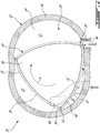
Fig. 2 is a schematic cross-sectional view of a rotary internal combustion engine in accordance with a particular embodiment; -
Fig. 3 is a schematic view of an engine assembly in accordance with one embodiment; and -
Fig. 4 is a schematic cross-sectional view of an ejector pump that may be used with the engine assembly ofFig. 3 . - Referring to
Fig. 1 , acompound engine system 8 is schematically shown. Thesystem 8 includes acompressor 11 and aturbine 13 which are connected by ashaft 15, and which act as a turbocharger to one or morerotary engines 10. Thecompressor 11 may be a single-stage or multiple-stage centrifugal device and/or an axial device. Arotary engine 10, or a plurality of rotary engines, receives compressed air from thecompressor 11. The air optionally circulates through anintercooler 16 between thecompressor 11 and the rotary engine(s) 10. - The exhaust gas exiting the
rotary engine 10 is supplied to thecompressor turbine 13 and also to apower turbine 17, theturbines turbines - Energy is extracted from the exhaust gas by the
compressor turbine 13 to drive thecompressor 11 via the connectingshaft 15, and by thepower turbine 17 to drive anoutput shaft 19. Theoutput shaft 19 may be connected via agear system 21 to ashaft 22 connected to the rotary engine(s) 10. The combined output on theshafts system 8 is integrated. This power may be delivered through a gearbox (not shown) that conditions the output speed of theshafts shafts - Although not shown, the
system 8 also includes a cooling system, including a circulation system for a coolant to cool the outer body of the rotary engine (e.g. water-ethylene, oil, air), an oil coolant for the internal mechanical parts of the rotary engine, one or more coolant heat exchangers, etc. - The
compound engine system 8 may be as described inLents et al.'s US patent No. 7,753,036 issued July 13, 2010 or as described inJulien et al.'s US patent No. 7,775,044 issued August 17, 2010 . - The
rotary engine 10 forms the core of the compoundcycle engine system 8. Referring toFig. 2 , the rotaryinternal combustion engine 10, known as a Wankel engine, is schematically shown. Therotary combustion engine 10 comprises anouter body 12 having axially-spacedend walls 14 with aperipheral wall 18 extending therebetween to form arotor cavity 20. The inner surface of theperipheral wall 18 of thecavity 20 has a profile defining two lobes, which is preferably an epitrochoid. - An inner body or
rotor 24 is received within thecavity 20. Therotor 24 has axially spaced end faces 26 adjacent to the outerbody end walls 14, and aperipheral face 28 extending therebetween. Theperipheral face 28 defines three circumferentially-spacedapex portions 30, and a generally triangular profile with outwardlyarched sides 36. Theapex portions 30 are in sealing engagement with the inner surface ofperipheral wall 18 to form three rotatingcombustion chambers 32 between theinner rotor 24 andouter body 12. The geometrical axis of therotor 24 is offset from and parallel to the axis of theouter body 12. - The
combustion chambers 32 are sealed. In the embodiment shown, eachrotor apex portion 30 has anapex seal 52 extending from oneend face 26 to the other and biased radially outwardly against theperipheral wall 18. Anend seal 54 engages each end of eachapex seal 52 and is biased against therespective end wall 14. Each end face 26 of therotor 24 has at least one arc-shapedface seal 60 running from eachapex portion 30 to eachadjacent apex portion 30, adjacent to but inwardly of the rotor periphery throughout its length, in sealing engagement with theend seal 54 adjacent each end thereof and biased into sealing engagement with theadjacent end wall 14. Alternate sealing arrangements are also possible. - Although not shown in the Figures, the
rotor 24 is journaled on an eccentric portion of a shaft such that the shaft rotates therotor 24 to perform orbital revolutions within thestator cavity 20. The shaft rotates three times for each complete rotation of therotor 24 as it moves around thestator cavity 20. Oil seals are provided around the eccentric to impede leakage flow of lubricating oil radially outwardly thereof between the respectiverotor end face 26 and outerbody end wall 14. During each rotation of therotor 24, eachchamber 32 varies in volumes and moves around thestator cavity 20 to undergo the four phases of intake, compression, expansion and exhaust, these phases being similar to the strokes in a reciprocating-type internal combustion engine having a four-stroke cycle. - The engine includes a
primary inlet port 40 in communication with a source of air, anexhaust port 44, and anoptional purge port 42 also in communication with the source of air (e.g. a compressor) and located between the inlet andexhaust ports ports end wall 14 of in theperipheral wall 18. In the embodiment shown, theinlet port 40 and purgeport 42 are defined in theend wall 14 and communicate with asame intake duct 34 defined as a channel in theend wall 14, and theexhaust port 44 is defined through theperipheral wall 18. Alternate configurations are possible. - In a particular embodiment, fuel such as kerosene (jet fuel) or other suitable fuel is delivered into the
chamber 32 through a fuel port (not shown) such that thechamber 32 is stratified with a rich fuel-air mixture near the ignition source and a leaner mixture elsewhere, and the fuel-air mixture may be ignited within the housing using any suitable ignition system known in the art (e.g. spark plug, glow plug). In a particular embodiment, therotary engine 10 operates under the principle of the Miller or Atkinson cycle, with its compression ratio lower than its expansion ratio, through appropriate relative location of theprimary inlet port 40 andexhaust port 44. - Referring to
Fig. 3 , an engine assembly is generally shown at 100. Theengine assembly 100 may incorporate the compoundcycle engine system 8 described herein above with reference toFig. 1 and may include therotary engine 10 described above with reference toFig. 2 . Theengine 10 may however be any combustion engine, such as a gas turbine engine, a piston engine, a rotary engine, and so on. The disclosed engine assembly may also be implemented as a gas turbine engine used as an Auxiliary Power Unit (APU) in an aircraft. Accordingly, the term "combustion engine" as used herein is understood to include all of these types of engines (reciprocating combustion engines such as piston engines, rotating combustion engines such as rotary or Wankel engines, continuous flow engines such as gas turbine engines, etc.), and is therefore defined as any engine having one or more combustion chambers and having a fuel system feeding fuel to the combustion chamber(s). As will be described further below, the fuel system of the present engines uses common rail injection. - The
engine assembly 100 includes afuel injection system 102 for providing fuel to thecombustion engine 10 from a fuel source S, which, in the embodiment shown, comprises a fuel tank. As shown, thefuel injection system 102 includes one or more high-pressure pump(s) 104 and a common-rail injector 106. The common-rail injector 106 includes acommon rail 108 and individual injectors, also referred to as common-rail injectors 110. The common-rail 108 is in fluid communication with each of theinjectors 110. - In the embodiment shown, the
engine assembly 100 includes acontroller 105, which may be a Full Authority Digital Engine Control (FADEC). Thecontroller 105 may be operatively connected to apower lever 107, which may be manually operable by a pilot of an aircraft equipped with the disclosedengine assembly 100. Thecontroller 105 communicates with a highpressure fuel sensor 109, which is operatively connected to the high-pressure pump(s) 104 for determining fuel pressure, and with aspeed sensor 111, which is operatively connected to theengine 10 for determining a speed of theengine 10. By receiving pressure and speed data from the pressure andfuel sensors controller 105 controls an amount of fuel to be injected by theinjectors 110 so that theengine 10 delivers the power required by the pilot via thepower lever 107. - Still referring to
Fig. 3 , each of thefuel injectors 110 includes aninlet 110a, afirst outlet 110b, and asecond outlet 110c. Theinlet 110a is fluidly connected to the source S of fuel, in the embodiment shown via the high-pressure pump(s) 104 and thecommon rail 108. Thefirst outlet 110b is fluidly connected to the combustion chamber 32 (Fig. 2 ) of theinternal combustion engine 10. Thesecond outlet 110c is configured for expelling a backflow F of fuel from theinjectors 110. - In a particular embodiment, the
injector 110 includes housings and pistons movable within the housings from a first position in which the piston blocks thefirst outlet 110b of theinjector 110 to a second position in which the piston is distanced from thefirst outlet 110b for allowing the fuel from the source of fuel S to be injected in the combustion chamber 32 (Fig. 2 ). Movement of the piston is induced by a pressure differential created by the high-pressure pumps 104. When the piston moves from the first position to the second position, a portion of the fuel that enters theinjector 110 via itsinlet 110a is not injected in thecombustion chamber 32 and is expelled out of theinjector 110 while bypassing thecombustion chamber 32. The backflow F corresponds to this portion of the fuel that is expelled via thesecond outlet 110c of thefuel injector 110. - The temperature and pressure of the fuel increases as a result of its passage through the high-pressure pump(s) 104. In use, the fuel that exits the
injector 110 via thesecond outlet 110c is typically simply redirected toward the source of fuel S. As will be seen herein below, it is herein proposed to use the backflow F of fuel. - The
fuel injection system 102 further has a fuel circuit C including amain conduit 112, for suppling the fuel from the source of fuel S to theinjector 110, and areturn conduit 114 for receiving the backflow F of fuel. - The fuel circuit C may include a
fuel pump 115, also referred to as a boost pump, which may be fluidly connected on themain conduit 112 and configured to draw fuel from the fuel source (e.g., fuel tank) S and to direct the drawn fuel to the high-pressure pump(s) 104. Ametering valve 117 may be fluidly connected to themain conduit 112 upstream of the high-pressure pumps 104 for controlling a flow rate of fuel entering the high-pressure pumps 104. As shown, themetering valve 117 is operatively connected to thecontroller 105 for feeding data thereto about a flow rate of fuel entering the high-pressure fuel pumps 104. Afuel filter 119 may be fluidly connected to themain conduit 112 upstream of the high-pressure pump 104. In the embodiment shown, thefuel filter 119 is located upstream of thepump 115 relative to a flow of fuel from the fuel source S to the high-pressure fuel pump(s) 104. - In the embodiment shown, a pressure regulating valve 120 is fluidly connected to the fuel circuit C. The valve 120 has an
inlet 120a and anoutlet 120b fluidly connectable to theinlet 120a. The valve 120 further has acontrol inlet 120c whose function is described below. - The valve 120 has a
member 120d movable between a close position (as shown) and an open position (not shown). In the close position, a flow of fuel from themain fuel conduit 112 to thereturn conduit 114 is permitted. Theinlet 120a of the valve 120 is fluidly connected to theoutlet 120b of the valve 120 in the open position of themember 120d. In the embodiment shown, themember 120d is biased in the close position using a biasingmember 120e, which may be a spring. - In the embodiment shown, the high-pressure pump(s) 104 have a
control outlet 104a fluidly connected to thecontrol inlet 120c of the pressure regulating valve 120. The pressure of the fuel entering the high-pressure pumps 104 from the fuel source S is preferably within a given range. If the pressure of the fuel entering the high-pressure pump(s) 104 is above a given pressure threshold, a pressure at thecontrol outlet 104a increases and pushes the valve 120 from the close position to the open position thereby allowing fuel to flow from themain fuel conduit 112 to thereturn conduit 114. In other words, the pressure regulating valve 120 provides an escape route for excess fuel that would otherwise increase inlet fuel pressure of the high-pressure pump(s) 104 above the given pressure threshold. - In the embodiment shown, the high-pressure pump(s) 104 is fluidly connected to the
injectors 110 viafuel conduits 124. Each of theinjectors 110 may have itsinlet 110a fluidly connected to the high-pressure pump 104 via a respective one of thefuel conduits 124. In the depicted embodiment, abypass conduit 126 is fluidly connected to thefuel conduits 124. Thebypass conduit 126 may have a plurality of upstream connection points 126a each being fluidly connected to a respective one of thefuel conduits 124. Thebypass conduit 126 has adownstream connection point 126b that may be connected to thereturn conduit 114. In the embodiment shown, thedownstream connection point 126b of thebypass conduit 126 is fluidly connected to thereturn conduit 114 downstream of thesecond outlets 110c of theinjectors 110 relative to a direction of the backflow F circulating in thereturn conduit 114. - The fuel circulating in the
fuel conduits 124 between thehigh pressure pump 104 and theinjectors 110 is at high pressure (e.g., 500 bars) and at high temperature as it has been compressed by the high pressure pump(s) 104. - In some cases, it might be advantageous to leverage the backflow of fuel F. Referring also to
Fig. 4 , theengine assembly 100 includes anejector pump 116. Theejector pump 116 may be located upstream of thepump 115 and upstream of thefilter 119. Other configurations are contemplated. For instance, theejector pump 116 may be located within the fuel tank. Theejector pump 116 has amotive flow inlet 116a, an entrainedflow inlet 116b and anoutlet 116c. Theejector pump 116 may include a convergingsection 116d for accelerating the fuel received through themotive flow inlet 116a. - The
motive flow inlet 116a of theejector pump 116 may be connected to thesecond injector outlets 110c of the common-rail injectors 110, to thefuel conduits 124 connecting thepump 104 to the common-rail injectors 110, or to both of thesecond injector outlets 110c and thefuel conduits 124. - In the embodiment shown, the
motive flow inlet 116a is connected to thesecond injector outlets 110c of the common-rail injectors 110 and selectively connected to thefuel conduits 124 when it is required to increase a flow rate of fuel injected to themotive flow inlet 116a. In the depicted embodiment, themotive flow inlet 116a may be fluidly connected to thefuel conduits 124 via thebypass conduit 126 and via thereturn conduit 114. Other configurations are contemplated without departing from the scope of the present disclosure. - The
ejector pump 116 receives the backflow F of fuel and/or a flow of fuel from thefuel lines 126 fluidly connecting the high-pressure pump 104 to the common-rail injectors 110 and injects said flow through aconduit 116e. Theconduit 116e is fluidly connected to themotive flow inlet 116a, to the entrainedflow inlet 116b, and to theoutlet 116c. Injection of the fuel from themotive flow inlet 116a into theconduit 116e creates a depression around a stream or jet of the fuel injected through theinlet 116a. This depression has a suctioning effect that draws a flow of fuel through the entrainedflow inlet 116b. In other words, the depression created by the injection of the fuel through themotive flow inlet 116a entrains a secondary flow via the entrainedflow inlet 116b. Theoutlet 116c of theejector pump 116, which is defined by theconduit 116e and which may define a divergingsection 116f, outputs a flow resulting from a combination of the motive flow received via theinlet 116a and the entrained flow received via the entrainedflow inlet 116b. Consequently, thejet pump 116 is able to pump a flow of fuel using another flow of fuel from another source. In a particular embodiment, thedivergent section 116f transfers kinetic energy of the fuel to potential energy. In a particular embodiment, the disclosed system takes advantage of waste energy coming out oflines 110c by bringing it as a motive flow to increase or improve suction lift at the engine inlet. Using this usually wasted energy may allow to avoid using an oversized pump to draw the fuel from the fuel tank, to reduce the complexity of the system, and to completely operate the system without the pump to meet suction lift requirements at engine inlet. - The motive flow created by the backflow of fuel F and/or by the fuel drawn from the
fuel conduits 124 may be used as a motive flow source to the aircraft equipped with the disclosedengine assembly 100. For instance, the motive flow source may be used to suctioned fuel from a fuel tank, to increase a flow rate of fuel through a given fuel conduit, to displace fuel from a given fuel tank to another, and any other suitable applications. - In the present embodiment, a
flow control device 113 is fluidly connected to thebypass conduit 126 between the upstream anddownstream connection points 126a, 126b. Theflow control device 113 may be a variable control orifice and may be used to vary a flow rate of the fuel circulating within thebypass conduit 126. A size of the orifice of the variable control orifice may be controlled manually and/or electronically to control a flow rate in thebypass conduit 126. Theflow control device 113 may close fluid communication between thefuel conduits 124 and theejector 116 via thebypass conduit 126. - In a particular embodiment, the disclosed fuel system allows to use the energy of the return flow coming out of the common rail injectors or directly from the common rail fuel lines to drive a motive flow within an ejector pump. This might allow to take advantage of the waste energy from the common rail system to create a suction effect within the low pressure fuel system or directly from the fuel tank using a motive flow. This concept might be applicable for all engine applications such as turboshaft, turboprop, turbofan and APU using common rail technology.
- In a particular embodiment, the disclosed fuel system takes advantage of the waste energy coming out of the common rail injectors; allow the possibility to replace the aircraft fuel tank boost pump by a simple motive flow to fulfill the suction lift; and is a low complexity system, which may be lighter and less expensive than boost pumps.
- For operating the aircraft engine, the fuel is pressurized for circulation through the common-
rail injection system 102; a portion of the pressurized fuel is circulated through themotive flow inlet 116a of theejector pump 116; and a flow is entrained through theejector pump 116 with the portion of the pressurized fuel circulating through themotive flow inlet 116a. - Herein, the portion of the pressurized fuel is the backflow of fuel F from the common-
rail injector 110 of the common-railfuel injection system 102. The backflow of fuel F is circulated through themotive flow inlet 116a of theejector pump 116. In the embodiment shown, the portion of the pressurized fuel is diverted from at least onefuel conduit 124 to the ejector pump; the at leastfuel conduit 124 connecting the high-pressure pump 104 to the common-rail injector 110 of the common-rail injection system 102. - In the embodiment shown, fuel is diverted from at least one
fuel conduit 124 and the flow is entrained with both of the backflow of fuel F and the diverted fuel. In the depicted embodiment, theejector pump 116 is fluidly connected to the source of fuel S, fuel from the source of fuel is entrained through theejector pump 116 using the portion of the pressurized fuel. - In the embodiment shown, a flow rate of the diverted portion of the pressurized fuel is regulated. The regulation of the flow rate may be achieved by constricting the flow of the diverted portion of the pressurized fuel. Herein, entraining the flow through the
ejector pump 116 with the portion of the pressurized fuel includes entraining fuel directly from the fuel tank S. - In the embodiment shown, entraining the flow through the
ejector pump 116 with the portion of the pressurized fuel includes suctioning the fuel through themain fuel conduit 112 that fluidly connects the source of fuel S to the high-pressure pump 104. - For supplying fuel to the aircraft engine having the common-rail
fuel injection system 102, fuel is pressurized to circulate through the common-rail injection system 102; a portion of the fuel is injected in the common-rail injectors 110 of the common-rail injection system 102 thereby generating the backflow of fuel F; and fuel to be pressurized is entrained from the source of fuel S though theejector pump 116 with the backflow of fuel F circulating through themotive flow inlet 116a of theejector pump 116. - In some cases, fuel is diverted from the
fuel conduits 124 and the fuel is entrained with both of the backflow of fuel F and the diverted fuel; thefuel conduits 124 connecting the high-pressure pump 104 to the common-rail injectors 110 of the common-rail injection system 102. - In the embodiment shown, a flow rate of the diverted fuel is regulated. The flow rate may be regulated by constricting a flow of the diverted fuel. In the embodiment shown, entraining the fuel from the source of fuel S through the
ejector pump 116 includes entraining the fuel directly from the fuel tank. In the illustrated embodiment, entraining the fuel from the source of fuel S through theejector pump 116 includes suctioning the fuel through themain fuel conduit 112 fluidly connecting the source of fuel S to the high-pressure pump 104. - Embodiments disclosed herein include:
- A. A method of operating an aircraft engine of an aircraft, the aircraft engine having a common-rail fuel injection system for injecting fuel into a combustion chamber of the aircraft engine, comprising: pressurizing fuel for circulation through the common-rail injection system; circulating a portion of the pressurized fuel through a motive flow inlet of an ejector pump; and entraining a flow through the ejector pump with the portion of the pressurized fuel circulating through the motive flow inlet.
- B. A method of supplying fuel to an aircraft engine having a common-rail fuel injection system, comprising: pressurizing fuel to circulate through the common-rail injection system; injecting a portion of the fuel in common-rail injectors of the common-rail injection system thereby generating a backflow of fuel; and entraining fuel to be pressurized from a source of fuel though an ejector pump with the backflow of fuel circulating through a motive flow inlet of the ejector pump.
Embodiments A and B may include any of the following elements, in any combinations:
Element 1: the portion of the pressurized fuel is a backflow of fuel from at least one common-rail injector of the common-rail fuel injection system, the method including circulating the backflow of fuel through the motive flow inlet of the ejector pump. Element 2: diverting the portion of the pressurized fuel from at least one fuel conduit to the ejector pump, the at least fuel conduit connecting a high-pressure pump to at least one common-rail injector of the common-rail injection system. Element 3: diverting fuel from at least one fuel conduit and entraining the flow with both of the backflow of fuel and the diverted fuel, the at least fuel conduit connecting a high-pressure pump to at least one common-rail injector of the common-rail injection system. Element 4: the ejector pump is fluidly connected to a source of fuel, the method comprising entraining fuel from the source of fuel through the ejector pump using the portion of the pressurized fuel. Element 5: regulating a flow rate of the diverted portion of the pressurized fuel. Element 6: regulating the flow rate includes constricting a flow of the diverted portion of the pressurized fuel. Element 7: entraining the flow through the ejector pump with the portion of the pressurized fuel includes entraining fuel directly from a fuel tank. Element 8: entraining the flow through the ejector pump with the portion of the pressurized fuel includes suctioning the fuel through a main fuel conduit fluidly connecting the source of fuel to a high-pressure pump. - C. An aircraft engine comprising: at least one combustion chamber; a fuel pump fluidly connected to a source of fuel; a common-rail injector having an injector inlet fluidly connected to the fuel pump via a fuel conduit, a first injector outlet fluidly connected to the at least one combustion chamber, and a second injector outlet for outputting a backflow of fuel; and an ejector pump having a motive flow inlet fluidly connected to one of the second injector outlet and the fuel conduit upstream of the common-rail injector, an entrained flow inlet for receiving fuel to be suctioned by the ejector pump.
- Embodiment C may include any of the following elements, in any combinations:
Element 9: the motive flow inlet is fluidly connected to both of the second injector outlet and the fuel conduit. Element 10: the motive flow inlet is fluidly connected to the fuel conduit via a bypass conduit, a flow control device being fluidly connected to the bypass conduit. Element 11: the source of fuel is a fuel tank, the ejector pump located within the fuel tank. Element 12: a main fuel conduit fluidly connecting the source of fuel to the fuel pump, and a boost pump fluidly connected to the main fuel conduit, the ejector pump being connected to the main fuel conduit upstream of the boost pump. - The above description is meant to be exemplary only, and one skilled in the art will recognize that changes may be made to the embodiments described without departing from the scope of the invention disclosed. Still other modifications which fall within the scope of the present invention will be apparent to those skilled in the art, in light of a review of this disclosure, and such modifications are intended to fall within the appended claims.
Claims (14)
- A method of operating an aircraft engine (10, 100) of an aircraft, the aircraft engine (10, 100) having a common-rail fuel injection system (102) for injecting fuel into a combustion chamber (32) of the aircraft engine (10, 100), the method comprising:pressurizing fuel for circulation through the common-rail fuel injection system (102);circulating a portion of the pressurized fuel through a motive flow inlet (116a) of an ejector pump (116); andentraining a flow through the ejector pump (116) with the portion of the pressurized fuel circulating through the motive flow inlet (116a).
- The method of claim 1, wherein the portion of the pressurized fuel is a backflow (F) of fuel from at least one common-rail injector (106, 110) of the common-rail fuel injection system (102), the method including circulating the backflow (F) of fuel through the motive flow inlet (116a) of the ejector pump (116).
- The method of claim 1 or 2, further comprising diverting the portion of the pressurized fuel from at least one fuel conduit (124) to the ejector pump (116), the at least one fuel conduit (124) connecting a high-pressure pump (104) to at least one common-rail injector (106, 110) of the common-rail fuel injection system (102).
- The method of claim 2, further comprising diverting fuel from at least one fuel conduit (124) and entraining the flow with both of the backflow (F) of fuel and the diverted fuel, the at least one fuel conduit (124) connecting a high-pressure pump (104) to at least one common-rail injector (106, 110) of the common-rail fuel injection system (102).
- The method of claim 3 or 4, further comprising regulating a flow rate of the diverted portion of the pressurized fuel.
- The method of claim 5, wherein regulating the flow rate includes constricting a flow of the diverted portion of the pressurized fuel.
- The method of any one of the preceding claims, wherein the ejector pump (116) is fluidly connected to a source (S) of fuel, the method comprising entraining fuel from the source (S) of fuel through the ejector pump (116) using the portion of the pressurized fuel.
- The method of any one of the preceding claims, wherein entraining the flow through the ejector pump (116) with the portion of the pressurized fuel includes entraining fuel directly from a fuel tank.
- The method of any one of the preceding claims, wherein entraining the flow through the ejector pump (116) with the portion of the pressurized fuel includes suctioning the fuel through a main fuel conduit (112) fluidly connecting the source (S) of fuel to a high-pressure pump (104).
- An aircraft engine (10, 100) comprising: at least one combustion chamber (32);
a fuel pump (104) fluidly connected to a source (S) of fuel; a common-rail injector (106, 110) having an injector inlet (110a) fluidly connected to the fuel pump (104) via a fuel conduit (124), a first injector outlet (110b) fluidly connected to the at least one combustion chamber (32), and a second injector outlet (110c) for outputting a backflow (F) of fuel; and an ejector pump (116) having a motive flow inlet (116a) fluidly connected to one of the second injector outlet (110c) and the fuel conduit (124) upstream of the common-rail injector (106, 110), an entrained flow inlet (116b) for receiving fuel to be suctioned by the ejector pump (116). - The aircraft engine of claim 10, wherein the motive flow inlet (116a) is fluidly connected to both of the second injector outlet (110c) and the fuel conduit (124).
- The aircraft engine of claim 10 or 11, wherein the motive flow inlet (116a) is fluidly connected to the fuel conduit (124) via a bypass conduit (126), a flow control device (113) being fluidly connected to the bypass conduit (126).
- The aircraft engine of any one of claims 10 to 12, wherein the source (S) of fuel is a fuel tank, and the ejector pump (116) is located within the fuel tank.
- The aircraft engine of any one of claims 10 to 13, further comprising a main fuel conduit (112) fluidly connecting the source (S) of fuel to the fuel pump (104), and a boost pump (115) fluidly connected to the main fuel conduit (112), the ejector pump (116) being connected to the main fuel conduit (112) upstream of the boost pump (115).
Applications Claiming Priority (1)
| Application Number | Priority Date | Filing Date | Title |
|---|---|---|---|
| US16/558,847 US11092126B2 (en) | 2019-09-03 | 2019-09-03 | Common-rail fuel system with ejector pump and method of use thereof |
Publications (2)
| Publication Number | Publication Date |
|---|---|
| EP3789597A1 true EP3789597A1 (en) | 2021-03-10 |
| EP3789597B1 EP3789597B1 (en) | 2025-03-19 |
Family
ID=72340192
Family Applications (1)
| Application Number | Title | Priority Date | Filing Date |
|---|---|---|---|
| EP20193952.7A Active EP3789597B1 (en) | 2019-09-03 | 2020-09-01 | Aircraft engine having a common-rail fuel system with ejector pump and method of operating an aircraft engine |
Country Status (6)
| Country | Link |
|---|---|
| US (1) | US11092126B2 (en) |
| EP (1) | EP3789597B1 (en) |
| CN (1) | CN112443436B (en) |
| CA (1) | CA3086125A1 (en) |
| ES (1) | ES3021248T3 (en) |
| PL (1) | PL3789597T3 (en) |
Cited By (1)
| Publication number | Priority date | Publication date | Assignee | Title |
|---|---|---|---|---|
| CZ310147B6 (en) * | 2023-07-10 | 2024-10-02 | Jan Novotný | A method to control output and consumption of a rotary combustion engine and an equipment to perform the invented method |
Citations (6)
| Publication number | Priority date | Publication date | Assignee | Title |
|---|---|---|---|---|
| US7753036B2 (en) | 2007-07-02 | 2010-07-13 | United Technologies Corporation | Compound cycle rotary engine |
| US7775044B2 (en) | 2003-02-24 | 2010-08-17 | Pratt & Whitney Canada Corp. | Low volumetric compression ratio integrated turbo-compound rotary engine |
| US20130036738A1 (en) * | 2010-04-28 | 2013-02-14 | Snecma | Turbomachine fueling system with jet pump |
| DE102012204750A1 (en) * | 2012-03-26 | 2013-09-26 | Robert Bosch Gmbh | Method for determining return pressure of injector of common-rail engine of motor car, involves detecting return pressure-dependent characteristic variables of injectors using control predetermined control parameter |
| DE102016122454A1 (en) * | 2015-12-28 | 2017-06-29 | Denso Corporation | Fuel supply control device |
| EP3258062A1 (en) * | 2016-06-17 | 2017-12-20 | Pratt & Whitney Canada Corp. | Rotary internal combustion engine with seal lubrication |
Family Cites Families (49)
| Publication number | Priority date | Publication date | Assignee | Title |
|---|---|---|---|---|
| GB541821A (en) * | 1940-06-11 | 1941-12-12 | Edward Donald Wynn | Improvements in or relating to fuel supply systems for internal-combustion engines |
| US3645094A (en) * | 1970-06-04 | 1972-02-29 | Gen Motors Corp | Fuel-pumping system with vortex-type flow resistor |
| US3894813A (en) * | 1974-01-30 | 1975-07-15 | Trw Inc | Aircraft fuel supply system having a dual stream tow-phase fluid pump |
| US3901025A (en) * | 1974-02-01 | 1975-08-26 | Piper Aircraft Corp | Aircraft engine fuel system |
| DE2804550A1 (en) * | 1978-02-03 | 1979-08-09 | Bosch Gmbh Robert | FUEL SYSTEM FOR COMBUSTION MACHINES |
| US4213741A (en) * | 1978-10-13 | 1980-07-22 | The Bendix Corporation | Variable flow ejector |
| US4339917A (en) * | 1979-06-13 | 1982-07-20 | The Garrett Corporation | Fuel delivery system and method |
| US4704070A (en) * | 1983-04-25 | 1987-11-03 | Iseman Walter J | Fuel system bubble dissipation device |
| US4794888A (en) * | 1988-01-04 | 1989-01-03 | Brunswick Corporation | Fuel puddle suction system for fuel injected engine |
| US5454532A (en) * | 1993-01-15 | 1995-10-03 | Fmc Corporation | Aircraft deicer pumping system |
| US5692479A (en) * | 1995-11-13 | 1997-12-02 | Ford Motor Company | Fuel delivery system for an internal combustion engine |
| EP0893598B1 (en) * | 1997-07-26 | 2003-05-28 | Delphi Technologies, Inc. | Fuel system |
| US6205981B1 (en) * | 1999-03-24 | 2001-03-27 | Siemens Automotive Corporation | Fuel recirculation for direct injection fuel system using a high pressure variable venturi pump |
| US6068022A (en) * | 1999-08-25 | 2000-05-30 | Schrader-Bridgeport International, Inc. | Jet pump with improved control valve and pressure relief valve therefore |
| DE10100700C1 (en) * | 2001-01-10 | 2002-08-01 | Bosch Gmbh Robert | Fuel injection system with pressure control in the return line |
| JP2003083191A (en) * | 2001-09-05 | 2003-03-19 | Hitachi Unisia Automotive Ltd | Fuel injection device |
| US7007452B1 (en) * | 2003-06-13 | 2006-03-07 | Woodward Governor Company | Fuel system for a gas turbine engine |
| JP4346619B2 (en) * | 2006-03-17 | 2009-10-21 | 株式会社ニフコ | Filter device |
| JP2008045536A (en) * | 2006-07-20 | 2008-02-28 | Toyota Industries Corp | DME engine fuel supply system |
| JP2008231997A (en) * | 2007-03-20 | 2008-10-02 | Mitsui Eng & Shipbuild Co Ltd | Fuel circulation system for internal combustion engines |
| US9441597B2 (en) * | 2010-05-28 | 2016-09-13 | Ford Global Technologies, Llc | Approach for controlling fuel flow with alternative fuels |
| KR101114530B1 (en) * | 2009-08-11 | 2012-02-27 | (주)모토닉 | LPI system for gas vehicle |
| KR101114393B1 (en) * | 2009-08-26 | 2012-02-14 | 현대자동차주식회사 | Elpiai Fuel Supply System |
| FR2958975B1 (en) * | 2010-04-15 | 2012-04-27 | Snecma | FUEL SUPPLY DEVICE OF AN AERONAUTICAL ENGINE |
| US8196567B2 (en) * | 2010-05-28 | 2012-06-12 | Ford Global Technologies, Llc | Approach for controlling fuel flow with alternative fuels |
| US8516997B2 (en) | 2010-05-28 | 2013-08-27 | Ford Global Technologies, Llc | Approach for controlling fuel flow with alternative fuels |
| DE102010031622A1 (en) * | 2010-07-21 | 2012-01-26 | Robert Bosch Gmbh | Kraftstofffördereinrichung |
| JP2012167559A (en) * | 2011-02-10 | 2012-09-06 | Denso Corp | Fuel injection device |
| US9039385B2 (en) * | 2011-11-28 | 2015-05-26 | Ford Global Technologies, Llc | Jet pump assembly |
| CN104040162B (en) * | 2012-01-03 | 2016-11-09 | 沃尔沃拉斯特瓦格纳公司 | Fuel system and corresponding method |
| DE102012200764B3 (en) * | 2012-01-19 | 2013-07-11 | Continental Automotive Gmbh | Common rail injection system for an internal combustion engine |
| DE102012101293B4 (en) * | 2012-02-17 | 2017-12-07 | L'orange Gmbh | Fuel injection device for heavy fuel engines |
| US9194232B2 (en) * | 2012-07-20 | 2015-11-24 | Pratt & Whitney Canada Corp. | Compound cycle engine |
| US9399947B2 (en) * | 2013-03-12 | 2016-07-26 | Pratt & Whitney Canada Corp. | Internal combustion engine with pilot and main injection |
| US9200563B2 (en) * | 2013-03-12 | 2015-12-01 | Pratt & Whitney Canada Corp. | Internal combustion engine with common rail pilot and main injection |
| US20150136091A1 (en) * | 2013-11-20 | 2015-05-21 | Hyundai Motor Company | Jet pump of fuel pump module for vehicle |
| JP6115523B2 (en) * | 2014-07-03 | 2017-04-19 | 株式会社デンソー | Fuel supply device |
| GB201419607D0 (en) * | 2014-11-04 | 2014-12-17 | Delphi International Operations Luxembourg S.�.R.L. | Fuel delivery system |
| JP6369336B2 (en) * | 2015-01-13 | 2018-08-08 | 株式会社デンソー | Fuel supply device |
| JP6409685B2 (en) * | 2015-06-03 | 2018-10-24 | 株式会社デンソー | Fuel supply device |
| US10465609B2 (en) * | 2015-12-18 | 2019-11-05 | Pratt & Whitney Canada Corp. | Engine fuel system for use with composite aircraft |
| US10118695B2 (en) * | 2016-03-18 | 2018-11-06 | Pratt & Whitney Canada Corp. | Directional control system and method of providing directional control |
| FR3049982B1 (en) * | 2016-04-12 | 2020-01-17 | Zodiac Aerotechnics | METHOD OF MANUFACTURING A STRAINER, STRAINER, AND EJECTOR COMPRISING SUCH A STRAINER |
| DE102018207010B3 (en) * | 2018-05-07 | 2019-07-04 | Continental Automotive Gmbh | Internal combustion engine and hybrid vehicle |
| US20190368449A1 (en) * | 2018-06-01 | 2019-12-05 | GM Global Technology Operations LLC | Returnless fuel system with accumulator |
| US10934012B2 (en) * | 2018-06-08 | 2021-03-02 | Textron Systems Corporation | Using a passive separator to separate air and fuel of a fuel mixture passively when delivering fuel to a combustion engine of an unmanned aerial vehicle |
| US10865728B2 (en) * | 2019-01-18 | 2020-12-15 | Pratt & Whitney Canada Corp. | Method of using backflow from common-rail fuel injector |
| US20200232431A1 (en) * | 2019-01-18 | 2020-07-23 | Pratt & Whitney Canada Corp. | Method of managing heat of injector backflow |
| US10738749B1 (en) * | 2019-01-18 | 2020-08-11 | Pratt & Whitney Canada Corp. | Method of using heat from fuel of common-rail injectors |
-
2019
- 2019-09-03 US US16/558,847 patent/US11092126B2/en active Active
-
2020
- 2020-07-07 CA CA3086125A patent/CA3086125A1/en active Pending
- 2020-09-01 PL PL20193952.7T patent/PL3789597T3/en unknown
- 2020-09-01 EP EP20193952.7A patent/EP3789597B1/en active Active
- 2020-09-01 ES ES20193952T patent/ES3021248T3/en active Active
- 2020-09-03 CN CN202010916373.9A patent/CN112443436B/en active Active
Patent Citations (6)
| Publication number | Priority date | Publication date | Assignee | Title |
|---|---|---|---|---|
| US7775044B2 (en) | 2003-02-24 | 2010-08-17 | Pratt & Whitney Canada Corp. | Low volumetric compression ratio integrated turbo-compound rotary engine |
| US7753036B2 (en) | 2007-07-02 | 2010-07-13 | United Technologies Corporation | Compound cycle rotary engine |
| US20130036738A1 (en) * | 2010-04-28 | 2013-02-14 | Snecma | Turbomachine fueling system with jet pump |
| DE102012204750A1 (en) * | 2012-03-26 | 2013-09-26 | Robert Bosch Gmbh | Method for determining return pressure of injector of common-rail engine of motor car, involves detecting return pressure-dependent characteristic variables of injectors using control predetermined control parameter |
| DE102016122454A1 (en) * | 2015-12-28 | 2017-06-29 | Denso Corporation | Fuel supply control device |
| EP3258062A1 (en) * | 2016-06-17 | 2017-12-20 | Pratt & Whitney Canada Corp. | Rotary internal combustion engine with seal lubrication |
Cited By (1)
| Publication number | Priority date | Publication date | Assignee | Title |
|---|---|---|---|---|
| CZ310147B6 (en) * | 2023-07-10 | 2024-10-02 | Jan Novotný | A method to control output and consumption of a rotary combustion engine and an equipment to perform the invented method |
Also Published As
| Publication number | Publication date |
|---|---|
| CN112443436A (en) | 2021-03-05 |
| CN112443436B (en) | 2025-02-07 |
| EP3789597B1 (en) | 2025-03-19 |
| PL3789597T3 (en) | 2025-06-23 |
| CA3086125A1 (en) | 2021-03-03 |
| US11092126B2 (en) | 2021-08-17 |
| ES3021248T3 (en) | 2025-05-26 |
| US20210062772A1 (en) | 2021-03-04 |
Similar Documents
| Publication | Publication Date | Title |
|---|---|---|
| US11584539B2 (en) | Auxiliary power unit with intercooler | |
| US11313273B2 (en) | Compound engine assembly with bleed air | |
| US10501200B2 (en) | Engine assembly for an auxiliary power unit | |
| CA2933990C (en) | Auxiliary power unit with excess air recovery | |
| WO1987004494A1 (en) | Compound engines | |
| US20180202357A1 (en) | Turbofan engine assembly with intercooler | |
| EP3789597B1 (en) | Aircraft engine having a common-rail fuel system with ejector pump and method of operating an aircraft engine | |
| US10865728B2 (en) | Method of using backflow from common-rail fuel injector | |
| US10738749B1 (en) | Method of using heat from fuel of common-rail injectors |
Legal Events
| Date | Code | Title | Description |
|---|---|---|---|
| PUAI | Public reference made under article 153(3) epc to a published international application that has entered the european phase |
Free format text: ORIGINAL CODE: 0009012 |
|
| STAA | Information on the status of an ep patent application or granted ep patent |
Free format text: STATUS: THE APPLICATION HAS BEEN PUBLISHED |
|
| AK | Designated contracting states |
Kind code of ref document: A1 Designated state(s): AL AT BE BG CH CY CZ DE DK EE ES FI FR GB GR HR HU IE IS IT LI LT LU LV MC MK MT NL NO PL PT RO RS SE SI SK SM TR |
|
| AX | Request for extension of the european patent |
Extension state: BA ME |
|
| STAA | Information on the status of an ep patent application or granted ep patent |
Free format text: STATUS: REQUEST FOR EXAMINATION WAS MADE |
|
| 17P | Request for examination filed |
Effective date: 20210910 |
|
| RBV | Designated contracting states (corrected) |
Designated state(s): AL AT BE BG CH CY CZ DE DK EE ES FI FR GB GR HR HU IE IS IT LI LT LU LV MC MK MT NL NO PL PT RO RS SE SI SK SM TR |
|
| STAA | Information on the status of an ep patent application or granted ep patent |
Free format text: STATUS: EXAMINATION IS IN PROGRESS |
|
| 17Q | First examination report despatched |
Effective date: 20230222 |
|
| GRAP | Despatch of communication of intention to grant a patent |
Free format text: ORIGINAL CODE: EPIDOSNIGR1 |
|
| STAA | Information on the status of an ep patent application or granted ep patent |
Free format text: STATUS: GRANT OF PATENT IS INTENDED |
|
| INTG | Intention to grant announced |
Effective date: 20241008 |
|
| GRAS | Grant fee paid |
Free format text: ORIGINAL CODE: EPIDOSNIGR3 |
|
| GRAA | (expected) grant |
Free format text: ORIGINAL CODE: 0009210 |
|
| STAA | Information on the status of an ep patent application or granted ep patent |
Free format text: STATUS: THE PATENT HAS BEEN GRANTED |
|
| AK | Designated contracting states |
Kind code of ref document: B1 Designated state(s): AL AT BE BG CH CY CZ DE DK EE ES FI FR GB GR HR HU IE IS IT LI LT LU LV MC MK MT NL NO PL PT RO RS SE SI SK SM TR |
|
| REG | Reference to a national code |
Ref country code: GB Ref legal event code: FG4D |
|
| REG | Reference to a national code |
Ref country code: CH Ref legal event code: EP |
|
| REG | Reference to a national code |
Ref country code: IE Ref legal event code: FG4D |
|
| REG | Reference to a national code |
Ref country code: DE Ref legal event code: R096 Ref document number: 602020047842 Country of ref document: DE |
|
| REG | Reference to a national code |
Ref country code: ES Ref legal event code: FG2A Ref document number: 3021248 Country of ref document: ES Kind code of ref document: T3 Effective date: 20250526 |
|
| PG25 | Lapsed in a contracting state [announced via postgrant information from national office to epo] |
Ref country code: RS Free format text: LAPSE BECAUSE OF FAILURE TO SUBMIT A TRANSLATION OF THE DESCRIPTION OR TO PAY THE FEE WITHIN THE PRESCRIBED TIME-LIMIT Effective date: 20250619 |
|
| PG25 | Lapsed in a contracting state [announced via postgrant information from national office to epo] |
Ref country code: FI Free format text: LAPSE BECAUSE OF FAILURE TO SUBMIT A TRANSLATION OF THE DESCRIPTION OR TO PAY THE FEE WITHIN THE PRESCRIBED TIME-LIMIT Effective date: 20250319 |
|
| REG | Reference to a national code |
Ref country code: LT Ref legal event code: MG9D |
|
| PG25 | Lapsed in a contracting state [announced via postgrant information from national office to epo] |
Ref country code: NO Free format text: LAPSE BECAUSE OF FAILURE TO SUBMIT A TRANSLATION OF THE DESCRIPTION OR TO PAY THE FEE WITHIN THE PRESCRIBED TIME-LIMIT Effective date: 20250619 |
|
| PG25 | Lapsed in a contracting state [announced via postgrant information from national office to epo] |
Ref country code: HR Free format text: LAPSE BECAUSE OF FAILURE TO SUBMIT A TRANSLATION OF THE DESCRIPTION OR TO PAY THE FEE WITHIN THE PRESCRIBED TIME-LIMIT Effective date: 20250319 |
|
| PG25 | Lapsed in a contracting state [announced via postgrant information from national office to epo] |
Ref country code: LV Free format text: LAPSE BECAUSE OF FAILURE TO SUBMIT A TRANSLATION OF THE DESCRIPTION OR TO PAY THE FEE WITHIN THE PRESCRIBED TIME-LIMIT Effective date: 20250319 |
|
| PG25 | Lapsed in a contracting state [announced via postgrant information from national office to epo] |
Ref country code: BG Free format text: LAPSE BECAUSE OF FAILURE TO SUBMIT A TRANSLATION OF THE DESCRIPTION OR TO PAY THE FEE WITHIN THE PRESCRIBED TIME-LIMIT Effective date: 20250319 Ref country code: GR Free format text: LAPSE BECAUSE OF FAILURE TO SUBMIT A TRANSLATION OF THE DESCRIPTION OR TO PAY THE FEE WITHIN THE PRESCRIBED TIME-LIMIT Effective date: 20250620 |
|
| REG | Reference to a national code |
Ref country code: NL Ref legal event code: MP Effective date: 20250319 |
|
| PG25 | Lapsed in a contracting state [announced via postgrant information from national office to epo] |
Ref country code: NL Free format text: LAPSE BECAUSE OF FAILURE TO SUBMIT A TRANSLATION OF THE DESCRIPTION OR TO PAY THE FEE WITHIN THE PRESCRIBED TIME-LIMIT Effective date: 20250319 |
|
| PG25 | Lapsed in a contracting state [announced via postgrant information from national office to epo] |
Ref country code: SE Free format text: LAPSE BECAUSE OF FAILURE TO SUBMIT A TRANSLATION OF THE DESCRIPTION OR TO PAY THE FEE WITHIN THE PRESCRIBED TIME-LIMIT Effective date: 20250319 |
|
| REG | Reference to a national code |
Ref country code: CH Ref legal event code: U11 Free format text: ST27 STATUS EVENT CODE: U-0-0-U10-U11 (AS PROVIDED BY THE NATIONAL OFFICE) Effective date: 20251001 |
|
| PG25 | Lapsed in a contracting state [announced via postgrant information from national office to epo] |
Ref country code: SM Free format text: LAPSE BECAUSE OF FAILURE TO SUBMIT A TRANSLATION OF THE DESCRIPTION OR TO PAY THE FEE WITHIN THE PRESCRIBED TIME-LIMIT Effective date: 20250319 |
|
| PG25 | Lapsed in a contracting state [announced via postgrant information from national office to epo] |
Ref country code: PT Free format text: LAPSE BECAUSE OF FAILURE TO SUBMIT A TRANSLATION OF THE DESCRIPTION OR TO PAY THE FEE WITHIN THE PRESCRIBED TIME-LIMIT Effective date: 20250721 |
|
| PGFP | Annual fee paid to national office [announced via postgrant information from national office to epo] |
Ref country code: DE Payment date: 20250820 Year of fee payment: 6 |
|
| PGFP | Annual fee paid to national office [announced via postgrant information from national office to epo] |
Ref country code: IT Payment date: 20250820 Year of fee payment: 6 Ref country code: PL Payment date: 20250825 Year of fee payment: 6 |
|
| PGFP | Annual fee paid to national office [announced via postgrant information from national office to epo] |
Ref country code: GB Payment date: 20250820 Year of fee payment: 6 |
|
| PGFP | Annual fee paid to national office [announced via postgrant information from national office to epo] |
Ref country code: AT Payment date: 20250822 Year of fee payment: 6 Ref country code: FR Payment date: 20250820 Year of fee payment: 6 |
|
| PG25 | Lapsed in a contracting state [announced via postgrant information from national office to epo] |
Ref country code: EE Free format text: LAPSE BECAUSE OF FAILURE TO SUBMIT A TRANSLATION OF THE DESCRIPTION OR TO PAY THE FEE WITHIN THE PRESCRIBED TIME-LIMIT Effective date: 20250319 |
|
| PGFP | Annual fee paid to national office [announced via postgrant information from national office to epo] |
Ref country code: CZ Payment date: 20250827 Year of fee payment: 6 |
|
| PG25 | Lapsed in a contracting state [announced via postgrant information from national office to epo] |
Ref country code: RO Free format text: LAPSE BECAUSE OF FAILURE TO SUBMIT A TRANSLATION OF THE DESCRIPTION OR TO PAY THE FEE WITHIN THE PRESCRIBED TIME-LIMIT Effective date: 20250319 |
|
| PG25 | Lapsed in a contracting state [announced via postgrant information from national office to epo] |
Ref country code: SK Free format text: LAPSE BECAUSE OF FAILURE TO SUBMIT A TRANSLATION OF THE DESCRIPTION OR TO PAY THE FEE WITHIN THE PRESCRIBED TIME-LIMIT Effective date: 20250319 |
|
| PG25 | Lapsed in a contracting state [announced via postgrant information from national office to epo] |
Ref country code: IS Free format text: LAPSE BECAUSE OF FAILURE TO SUBMIT A TRANSLATION OF THE DESCRIPTION OR TO PAY THE FEE WITHIN THE PRESCRIBED TIME-LIMIT Effective date: 20250719 |
|
| REG | Reference to a national code |
Ref country code: DE Ref legal event code: R097 Ref document number: 602020047842 Country of ref document: DE |
|
| PG25 | Lapsed in a contracting state [announced via postgrant information from national office to epo] |
Ref country code: DK Free format text: LAPSE BECAUSE OF FAILURE TO SUBMIT A TRANSLATION OF THE DESCRIPTION OR TO PAY THE FEE WITHIN THE PRESCRIBED TIME-LIMIT Effective date: 20250319 |
|
| PGFP | Annual fee paid to national office [announced via postgrant information from national office to epo] |
Ref country code: CH Payment date: 20251001 Year of fee payment: 6 |
|
| PLBE | No opposition filed within time limit |
Free format text: ORIGINAL CODE: 0009261 |
|
| STAA | Information on the status of an ep patent application or granted ep patent |
Free format text: STATUS: NO OPPOSITION FILED WITHIN TIME LIMIT |
|
| REG | Reference to a national code |
Ref country code: CH Ref legal event code: L10 Free format text: ST27 STATUS EVENT CODE: U-0-0-L10-L00 (AS PROVIDED BY THE NATIONAL OFFICE) Effective date: 20260128 |
|
| PGFP | Annual fee paid to national office [announced via postgrant information from national office to epo] |
Ref country code: ES Payment date: 20251001 Year of fee payment: 6 |
|
| 26N | No opposition filed |
Effective date: 20251222 |
|
| REG | Reference to a national code |
Ref country code: AT Ref legal event code: UEP Ref document number: 1777124 Country of ref document: AT Kind code of ref document: T Effective date: 20250319 |
|
| PG25 | Lapsed in a contracting state [announced via postgrant information from national office to epo] |
Ref country code: LU Free format text: LAPSE BECAUSE OF NON-PAYMENT OF DUE FEES Effective date: 20250901 |
|
| REG | Reference to a national code |
Ref country code: BE Ref legal event code: MM Effective date: 20250930 |
|
| PG25 | Lapsed in a contracting state [announced via postgrant information from national office to epo] |
Ref country code: LT Free format text: LAPSE BECAUSE OF FAILURE TO SUBMIT A TRANSLATION OF THE DESCRIPTION OR TO PAY THE FEE WITHIN THE PRESCRIBED TIME-LIMIT Effective date: 20250319 |
|
| PG25 | Lapsed in a contracting state [announced via postgrant information from national office to epo] |
Ref country code: MC Free format text: LAPSE BECAUSE OF FAILURE TO SUBMIT A TRANSLATION OF THE DESCRIPTION OR TO PAY THE FEE WITHIN THE PRESCRIBED TIME-LIMIT Effective date: 20250319 |
|
| PG25 | Lapsed in a contracting state [announced via postgrant information from national office to epo] |
Ref country code: IE Free format text: LAPSE BECAUSE OF NON-PAYMENT OF DUE FEES Effective date: 20250901 Ref country code: BE Free format text: LAPSE BECAUSE OF NON-PAYMENT OF DUE FEES Effective date: 20250930 |