EP3789532A1 - Foldable hanger and heating device - Google Patents
Foldable hanger and heating device Download PDFInfo
- Publication number
- EP3789532A1 EP3789532A1 EP18915860.3A EP18915860A EP3789532A1 EP 3789532 A1 EP3789532 A1 EP 3789532A1 EP 18915860 A EP18915860 A EP 18915860A EP 3789532 A1 EP3789532 A1 EP 3789532A1
- Authority
- EP
- European Patent Office
- Prior art keywords
- hanging
- hanger
- drying
- state
- sliding
- Prior art date
- Legal status (The legal status is an assumption and is not a legal conclusion. Google has not performed a legal analysis and makes no representation as to the accuracy of the status listed.)
- Granted
Links
Images


Classifications
-
- D—TEXTILES; PAPER
- D06—TREATMENT OF TEXTILES OR THE LIKE; LAUNDERING; FLEXIBLE MATERIALS NOT OTHERWISE PROVIDED FOR
- D06F—LAUNDERING, DRYING, IRONING, PRESSING OR FOLDING TEXTILE ARTICLES
- D06F57/00—Supporting means, other than simple clothes-lines, for linen or garments to be dried or aired
- D06F57/08—Folding stands
-
- D—TEXTILES; PAPER
- D06—TREATMENT OF TEXTILES OR THE LIKE; LAUNDERING; FLEXIBLE MATERIALS NOT OTHERWISE PROVIDED FOR
- D06F—LAUNDERING, DRYING, IRONING, PRESSING OR FOLDING TEXTILE ARTICLES
- D06F57/00—Supporting means, other than simple clothes-lines, for linen or garments to be dried or aired
- D06F57/12—Supporting means, other than simple clothes-lines, for linen or garments to be dried or aired specially adapted for attachment to walls, ceilings, stoves, or other structures or objects
- D06F57/127—Supporting means, other than simple clothes-lines, for linen or garments to be dried or aired specially adapted for attachment to walls, ceilings, stoves, or other structures or objects for attachment or suspension to central heating radiators
-
- F—MECHANICAL ENGINEERING; LIGHTING; HEATING; WEAPONS; BLASTING
- F24—HEATING; RANGES; VENTILATING
- F24D—DOMESTIC- OR SPACE-HEATING SYSTEMS, e.g. CENTRAL HEATING SYSTEMS; DOMESTIC HOT-WATER SUPPLY SYSTEMS; ELEMENTS OR COMPONENTS THEREFOR
- F24D19/00—Details
-
- A—HUMAN NECESSITIES
- A47—FURNITURE; DOMESTIC ARTICLES OR APPLIANCES; COFFEE MILLS; SPICE MILLS; SUCTION CLEANERS IN GENERAL
- A47G—HOUSEHOLD OR TABLE EQUIPMENT
- A47G25/00—Household implements used in connection with wearing apparel; Dress, hat or umbrella holders
- A47G25/02—Dress holders; Dress suspending devices; Clothes-hanger assemblies; Clothing lifters
- A47G25/06—Clothes hooks; Clothes racks; Garment-supporting stands with swingable or extending arms
- A47G25/0685—Collapsible clothes racks, e.g. swingable, foldable, extendible
-
- D—TEXTILES; PAPER
- D06—TREATMENT OF TEXTILES OR THE LIKE; LAUNDERING; FLEXIBLE MATERIALS NOT OTHERWISE PROVIDED FOR
- D06F—LAUNDERING, DRYING, IRONING, PRESSING OR FOLDING TEXTILE ARTICLES
- D06F57/00—Supporting means, other than simple clothes-lines, for linen or garments to be dried or aired
- D06F57/06—Supporting means, other than simple clothes-lines, for linen or garments to be dried or aired comprising vertical members connected by horizontal bars
-
- D—TEXTILES; PAPER
- D06—TREATMENT OF TEXTILES OR THE LIKE; LAUNDERING; FLEXIBLE MATERIALS NOT OTHERWISE PROVIDED FOR
- D06F—LAUNDERING, DRYING, IRONING, PRESSING OR FOLDING TEXTILE ARTICLES
- D06F57/00—Supporting means, other than simple clothes-lines, for linen or garments to be dried or aired
- D06F57/12—Supporting means, other than simple clothes-lines, for linen or garments to be dried or aired specially adapted for attachment to walls, ceilings, stoves, or other structures or objects
Definitions
- the invention relates to a technical field of hangers, and in particular to a foldable hanger and a heating device.
- a foldable hanger applied to an electric heater known to inventors includes a frame, supporting feet hinged at two ends of the frame and hanger rod rack at two sides of the frame.
- the hanger rod rack includes a hanging rod and a rotating arm supporting the hanging rod. One end of the rotating arm is hinged on the frame which is divided into left frame and right frame hinged with each other.
- a support has a left support and right support hinged with each other.
- the hinged structure needs to fold the left and right supports and the left and right frames respectively, so as to complete a storage of the foldable hanger, and an operation is also complex when unfolding. No matter in a packaging process or in a use process of users, each part needs to be folded or unfolded one by one, which increases disassembly and assembly steps and storage time.
- Some embodiments of the present invention provide a heating device with the foldable hanger.
- Some embodiments of the present invention provide a foldable hanger, which includes: a hanger body; folding feet movably connected to the hanger body and having a supporting state after unfolding and a storing state after folding; a hanging and drying member movably connected to the hanger body and having a hanging and drying state distant from the hanger body and a resetting state close to the hanger body; and a linkage mechanism disposed between the folding feet and the hanging and drying member.
- a change of a state of any one of the folding feet and the hanging and drying member drives, through the linkage mechanism, a state of the other of the folding feet and the hanging and drying member to change.
- the supporting state corresponds to the hanging and drying state
- the storing state corresponds to the resetting state.
- the folding feet are hinged on the hanger body; the hanging and drying member has a sliding part which is in sliding fit with a slide rail disposed on the hanger body; the linkage mechanism converts a reciprocating rotation of the folding feet to a reciprocating sliding of the hanging and drying member or converts a reciprocating sliding of the hanging and drying member to a reciprocating rotation of the folding feet.
- the linkage mechanism is an inclined wedge mechanism.
- the inclined wedge mechanism includes a linkage part disposed on the folding feet and a sliding block disposed on the hanger body; the sliding block is in bevel fit with the sliding part; a guide part cooperating with a guide structure disposed on the hanger body is also disposed on the sliding block; the linkage part pushes the sliding block to move along the guide structure, and the sliding block drives the sliding part to move along the slide rail, so that the hanging and drying member moves to the hanging and drying state; on the contrary, the hanging and drying member drives the folding feet to move through the sliding part, the sliding block and the linkage part.
- the guide structure is a through hole disposed at the bottom of the hanger body, the guide part is adapted to extend into the through hole, and the linkage part pushes the guide part to move along the through hole.
- the linkage part is a hinged end part of the folding feet.
- the inclined wedge mechanism further includes an elastic reset structure acting on the hanging and drying member and/or the folding feet; the elastic reset structure applies a first resetting force to move the hanging and drying member toward the resetting state; and/or, the elastic reset structure applies a second resetting force to move the folding feet toward the storing state.
- the linkage mechanism is a gear drive mechanism.
- the gear drive mechanism includes a gear disposed on a hinged end of the folding feet, a rack disposed on the sliding part, and a dual gear meshed with the gear and the rack respectively.
- the sliding part is a support rod in sliding fit with the slide rail.
- the hanging and drying member further includes a hanging and drying rod connected to a free end of the support rod.
- the hanger body is also provided with a fixed clothes drying board, and the hanging and drying rod is on a side of the fixed clothes drying board.
- the sliding part is a sliding slot in sliding fit with the slide rail.
- the hanging and drying member further includes a movable clothes drying board, and the sliding slot is disposed on the movable clothes drying board.
- Some embodiments of the present invention provide a heating device, which includes a heating body and the above foldable hanger, wherein the foldable hanger is detachably connected to the heating body.
- the heating device is an electric heater.
- orientation or position relationships indicated by terms “upper”, “lower”, “vertical”, “horizontal” and the like are orientation or position relationships shown in the drawings, are adopted not to indicate or imply that indicated devices or members must be in specific orientations or structured and operated in specific orientations but only to conveniently describe the invention and simplify descriptions.
- first and second are used for descriptive purposes only and are not to be construed as indicating or implying relative importance.
- mount and “connect” should be broadly understood.
- the terms refer to fixed connection and also refer to detachable connection or integrated connection.
- the terms refer to mechanical connection or electrical connection.
- the terms refer to direct mutual connection, also refer to indirect connection through a medium and refer to communication in two members.
- specific meanings of these terms in the invention can be understood according to a specific condition.
- a foldable hanger provided by the embodiment includes a hanger body 1, and folding feet 2 and a hanging and drying member movably connected to the hanger body 1, and a linkage mechanism disposed between the folding feet 2 and the hanging and drying member; the folding feet 2 have a supporting state after unfolding and a storing state after folding; the hanging and drying member has a hanging and drying state distant from the hanger body 1 and a resetting state close to the hanger body 1; a change of a state of the folding feet 2 drives, through the linkage mechanism, a state of the hanging and drying member to change; the supporting state corresponds to the hanging and drying state, and the storing state corresponds to the resetting state.
- a setting of the linkage mechanism can make the hanging and drying member away from or close to the hanger body 1 when the folding feet 2 are unfolded or folded, so that no matter in a process of packaging and transportation or in a use process of users, the hanger body can be unfolded or folded in one step without separately operating the feet and the hanging and drying member, which reduces operation steps, saves operation time, improves a user experience by completing an operation at one time, and makes a packaging, installation and storage process easier and more convenient.
- the hanger body 1 is rectangular, the folding feet 2 are hinged on the hanger body 1, and the hanging and drying member is in sliding fit with a slide rail on the hanger body 1 through its sliding part; the hanger body 1 is provided with the slide rail formed by a cavity, and the hanging and drying member includes the sliding part and a hanging and drying rod 3 disposed on the sliding part, the sliding part being a support rod 4 disposed in the cavity and capable of reciprocating sliding along the cavity, and the hanging and drying member being a hanging and drying state 3 connected to a free end of the support rod 4.
- the hanging and drying member slides close to the hanger body 1 while the user rotates and folds the folding feet 2, so that the hanging and drying member also moves to the resetting state while the feet are folded to the storing state; when the foldable hanger is installed or used, the hanging and drying member slides away from the hanger body 1 while the user rotates to unfold the folding feet 2, so that the hanging and drying member also moves to the hanging and drying state while the feet are unfolded to the supporting state.
- Two hanging and drying rods 3 are respectively located at two sides of the hanger body 1, and can extend away from the hanger body 1 or retract back towards the direction close to the hanger body 1.
- An inner wall of the cavity is provided with a clamping slot.
- the clamping slot is in tabling fit with an elastic clamping pin on an outer wall of the support rod 4 to prevent the support rod 4 from falling out of the cavity.
- the hanger body 1 is also disposed with a fixed clothes drying board 5, and two hanging and drying rods 3 are respectively located at two sides of the fixed clothes drying board 5.
- the hanging and drying rod 3 is in the resetting state, it is disposed close to the two sides of the fixed clothes drying board 5.
- the fixed clothes drying board 5 is provided with a plurality of through holes.
- the linkage mechanism is a inclined wedge mechanism
- the inclined wedge mechanism includes a linkage part 8 disposed on the folding feet 2 and a sliding block 6 disposed on the hanger body 1.
- An end portion of one end of the support rod 4 extended into the cavity is a bevel and the sliding block 6 has a bevel cooperated with the bevel, so that the sliding block 6 and the end portion of the support rod 4 form a bevel fit.
- the sliding block 6 is also provided with a guide part 7 cooperating with a guide structure disposed on hanger body 1;
- the guide structure is a through hole disposed on a bottom surface of hanger body 1, and an axial direction of the through hole is perpendicular to a sliding direction of support rod 4;
- the guide part 7 is a guide block disposed together with the sliding block 6, and the guide block, a contour of which adapts to a contour of the through hole, extends out of the through hole.
- the linkage part 8 is an end portion of a hinged end of the folding feet 2. When the folding feet 2 are fully unfolded, its end face pushes against the guide part 7 to drive the support rod 4 to slide.
- the inclined wedge mechanism further includes an elastic reset structure disposed on the hanging and drying member.
- the elastic reset structure is an elastic compression spring disposed between the cavity and the support rod 4. When the support rod 4 moves toward a direction extending out of the cavity, the elastic compression spring compresses; and when the folding feet 2 fold to the storing state, its hinged end gradually eliminates a push against a guide hole, and the support rod 4 retracts into the cavity under a first resetting force of the elastic compression spring.
- the elastic reset structure is helpful for the hanging and drying rod 3 to move to the resetting state with less effort and ease.
- a first radial lug boss extending outward is disposed on the support rod 4, an opening of the cavity is provided with a second radial lug boss extending inwards to prevent the support rod 4 from falling out, and the elastic compression spring is disposed between the first raidal lug boss and the second radial lug boss.
- Some embodiments of the present embodiment also provides a heating device, which includes a heating body and the foldable hanger detachably connected to the heating body.
- the foldable hanger is detachably mounted on the heating body, which is convenient to dry clothes; during storage, the foldable hanger is folded and stored directly by one-step operation, which is easy and convenient.
- the heating device is an electric heater
- the heating body is radiating fins
- the folding feet 2 of the foldable hanger are clamped above the radiating fins
- the hanger body is above the radiating fins
- the hanging and drying member is at two sides of the radiating fins.
- the hanging and drying member is a pair of movable clothes drying boards (9) and the hanging and drying rod (3) disposed on the outside of each movable clothes drying board (9);
- the movable clothes drying board (9) is in sliding fit with the slide rail on the hanger body (1) through its sliding part;
- the sliding part is sliding slots disposed at two ends of the movable clothes drying board (9), and
- the slide way is a plurality of convex block located at two ends of the hanger body (1) in a length direction; the pair of movable clothes drying boards (9) can close to or move away from each other through a sliding of the sliding slot along the convex block.
- the linkage mechanism is a gear drive mechanism.
- the gear drive mechanism includes a gear (10) disposed on the hinged end of the folding feet (2), a rack (11) disposed on the side wall of sliding part, and a dual gear (12) meshed with the gear (10) and the rack (11).
- the gear (10) on the folding feet (2) is meshed with a small gear (10) of the dual gear (12), and a big gear (10) of the dual gear (12) is meshed with the rack (11) on a side wall of the sliding part.
- the folding feet (2) rotate or the sliding part slides, so that the gear (10) or the rack (11) is driven to drive the dual gear (12) to rotate, thus realizing a sliding of the sliding part or a rotation of the folding feet (2), at this point, a rotation plane of the folding feet (2) is parallel to a sliding direction of the movable clothes drying board (9).
- the linkage mechanism is a gear (10) transmission mechanism.
- the gear transmission mechanism includes the gear (10) disposed on the hinged end of the folding feet (2), the rack (11) disposed on the side wall of the support rod (4), and the dual gear (12) meshed with the gear (10) and the rack (11) respectively.
- the gear (10) on the folding feet (2) is meshed with the small gear (10) of the dual gear (12), and the big gear (10) of the dual gear (12) is meshed with the rack (11) on the side wall of the sliding part.
- the folding feet (2) rotate or the sliding part slides, so that the gear (10) or the rack (11) is driven to drive the dual gear (12) to rotate, thus realizing the sliding of the sliding part or the rotation of the folding feet (2), at this point, the rotation plane of the folding feet (2) is parallel to the sliding direction of the support rod (4).
- the support rod is provided with a groove extending axially, and the elastic compression spring is disposed in the groove.
- One end of the elastic compression spring is abutted against an inner end of the groove, and the other end of the elastic compression spring is abutted against the second radial lug boss extending inward, which is disposed at the opening of the cavity to prevent the support rod from falling out.
- the elastic reset structure is disposed between the folding feet and the hanger body.
- the elastic reset structure is the elastic compression spring which applies the second resetting force to move the folding feet toward the storing state.
- the folding feet rotate to the supporting state, its linkage part pushes against the sliding block, and the sliding part of the hanging and drying member moves to the hanging and drying state;
- the hanging and drying member is pushed to move to the resetting state, its sliding part pushes against the sliding block, and the folding feet rotates to the storing state under an action of the second resetting force.
- the guide structure is a guide bar disposed on the hanger body and perpendicular to the slide rail.
- the sliding block has a guide groove matching with the guide bar.
- the sliding block is disposed in the hanger body, and reciprocating moves along the guide bar to push the sliding part to reciprocating slide.
- the linkage part is a protrusion on the folding feet.
- the protrusion pushes against the guide block.
- the heating device is water heater.
Landscapes
- Engineering & Computer Science (AREA)
- Textile Engineering (AREA)
- Physics & Mathematics (AREA)
- Thermal Sciences (AREA)
- Chemical & Material Sciences (AREA)
- Combustion & Propulsion (AREA)
- Mechanical Engineering (AREA)
- General Engineering & Computer Science (AREA)
- Holders For Apparel And Elements Relating To Apparel (AREA)
Abstract
Description
- The invention relates to a technical field of hangers, and in particular to a foldable hanger and a heating device.
- Electric heaters have become household necessities in areas lacking of central heating. In order to make functions diversified, the electric heaters on market are usually equipped with a detachable clothes drying hanger, which solves a problem that it is difficult to dry clothes in wet and cold winter while heating. The clothes drying hanger is generally set as foldable to reduce packaging and transportation costs and facilitate accommodation. For example, a foldable hanger applied to an electric heater known to inventors includes a frame, supporting feet hinged at two ends of the frame and hanger rod rack at two sides of the frame. The hanger rod rack includes a hanging rod and a rotating arm supporting the hanging rod. One end of the rotating arm is hinged on the frame which is divided into left frame and right frame hinged with each other. A support has a left support and right support hinged with each other. The hinged structure needs to fold the left and right supports and the left and right frames respectively, so as to complete a storage of the foldable hanger, and an operation is also complex when unfolding. No matter in a packaging process or in a use process of users, each part needs to be folded or unfolded one by one, which increases disassembly and assembly steps and storage time.
- Technical problems to be solved in the invention is to overcome defects of the foldable hanger known to inventors that there are too many folding and unfolding steps and operation is inconvenient, so as to provide a foldable hanger, the operation steps of which can be reduced, and folding and unfolding of which is easier and more convenient.
- Some embodiments of the present invention provide a heating device with the foldable hanger.
- The technical solutions of the invention are as follows.
- Some embodiments of the present invention provide a foldable hanger, which includes: a hanger body; folding feet movably connected to the hanger body and having a supporting state after unfolding and a storing state after folding; a hanging and drying member movably connected to the hanger body and having a hanging and drying state distant from the hanger body and a resetting state close to the hanger body; and a linkage mechanism disposed between the folding feet and the hanging and drying member. A change of a state of any one of the folding feet and the hanging and drying member drives, through the linkage mechanism, a state of the other of the folding feet and the hanging and drying member to change. The supporting state corresponds to the hanging and drying state, and the storing state corresponds to the resetting state.
- In some embodiments, the folding feet are hinged on the hanger body; the hanging and drying member has a sliding part which is in sliding fit with a slide rail disposed on the hanger body; the linkage mechanism converts a reciprocating rotation of the folding feet to a reciprocating sliding of the hanging and drying member or converts a reciprocating sliding of the hanging and drying member to a reciprocating rotation of the folding feet.
- In some embodiments, the linkage mechanism is an inclined wedge mechanism.
- In some embodiments, the inclined wedge mechanism includes a linkage part disposed on the folding feet and a sliding block disposed on the hanger body; the sliding block is in bevel fit with the sliding part; a guide part cooperating with a guide structure disposed on the hanger body is also disposed on the sliding block; the linkage part pushes the sliding block to move along the guide structure, and the sliding block drives the sliding part to move along the slide rail, so that the hanging and drying member moves to the hanging and drying state; on the contrary, the hanging and drying member drives the folding feet to move through the sliding part, the sliding block and the linkage part.
- In some embodiments, the guide structure is a through hole disposed at the bottom of the hanger body, the guide part is adapted to extend into the through hole, and the linkage part pushes the guide part to move along the through hole.
- In some embodiments, the linkage part is a hinged end part of the folding feet.
- In some embodiments, the inclined wedge mechanism further includes an elastic reset structure acting on the hanging and drying member and/or the folding feet; the elastic reset structure applies a first resetting force to move the hanging and drying member toward the resetting state; and/or, the elastic reset structure applies a second resetting force to move the folding feet toward the storing state.
- In some embodiments, the linkage mechanism is a gear drive mechanism.
- In some embodiments, the gear drive mechanism includes a gear disposed on a hinged end of the folding feet, a rack disposed on the sliding part, and a dual gear meshed with the gear and the rack respectively.
- In some embodiments, the sliding part is a support rod in sliding fit with the slide rail.
- In some embodiments, the hanging and drying member further includes a hanging and drying rod connected to a free end of the support rod.
- In some embodiments, the hanger body is also provided with a fixed clothes drying board, and the hanging and drying rod is on a side of the fixed clothes drying board.
- In some embodiments, the sliding part is a sliding slot in sliding fit with the slide rail.
- In some embodiments, the hanging and drying member further includes a movable clothes drying board, and the sliding slot is disposed on the movable clothes drying board.
- Some embodiments of the present invention provide a heating device, which includes a heating body and the above foldable hanger, wherein the foldable hanger is detachably connected to the heating body.
- In some embodiments, the heating device is an electric heater.
- The technical solutions of the invention have the following advantages.
- 1. The foldable hanger provided by the invention includes the hanger body, and the folding feet and the hanging and drying member movably connected to the hanger body, and the linkage mechanism disposed between the folding feet and the hanging and drying member; the folding feet have the supporting state after unfolding and the storing state after folding; the hanging and drying member has the hanging and drying state distant from the hanger body and the resetting state close to the hanger body; the change of the state of any one of the folding feet and the hanging and drying member is change, through the linkage mechanism, a state of the other of the folding feet and the hanging and drying member to change; the supporting state corresponds to the hanging and drying state, and the storing state corresponds to the resetting state. Therefore, a setting of the linkage mechanism makes the hanging and drying member away from or close to the hanger body when the folding feet are unfolded or folded, or makes the hanging and drying member to drive the folding feet to unfold or fold when being away from or close to the hanger body, so that no matter in a process of packaging and transportation or in a use process of users, the hanger body is unfolded or folded in one step without separately operating the feet and the hanging and drying member, which reduces operation steps, saves operation time, improves a user experience by completing an operation at one time, and makes a packaging, installation and storage process easier and more convenient.
- 2. For the foldable hanger provided by some embodiments of the present invention, the folding feet are hinged on the hanger body, the hanging and drying member is in sliding fit with the slide rail on the hanger body through its sliding part, and the linkage mechanism converts a reciprocating rotation of the folding feet to a reciprocating sliding of the hanging and drying member; in such a manner, when the foldable hanger is packaged or stored, the hanging and drying member moves close to the hanger body while the user folds the folding feet, so that the hanging and drying member also moves to the resetting state while the feet are folded to the storing state; when the foldable hanger is installed or used, the hanging and drying member moves away from the hanger body while the user unfolds the folding feet, so that the hanging and drying member also moves to the hanging and drying state while the folding feet are unfolded to the supporting state; or the linkage mechanism converts the reciprocating sliding of the hanging and drying member to the reciprocating rotation of the folding feet; in such a manner, when the foldable hanger is packaged or stored, the folding feet are folded while the user pushes the hanging and drying member to move close to the hanger body, so that the folding feet are folded to the storing state while the hanging and drying member moves to the resetting state; when the foldable hanger is installed or used, the folding feet are unfolded while the user pulls the hanging and drying member to move away from hanger body, so that the folding feet are unfolded to the supporting state while the hanging and drying member moves to the hanging and drying state.
- 3. For the foldable hanger provided by some embodiments of the present invention, the linkage mechanism is the inclined wedge mechanism; rotating movement of the folding feet and sliding movement of the hanging and drying member are converted through the inclined wedge mechanism, which has stable structure, uneasy damage and long service life.
- 4. For the foldable hanger provided by the invention, the inclined wedge mechanism includes the linkage part disposed on the folding feet and the sliding block disposed on the hanger body; the sliding block is in bevel fit with the sliding part; the guide part matching with the guide structure disposed on the hanger body is also disposed on the sliding block; the linkage part pushes the sliding block to move along the guide structure, and the sliding block drives the sliding part to move along the slide rail, so that the hanging and drying member moves to the hanging and drying state; the sliding block is in bevel fit with the sliding part, so that slide lift of the sliding block is converted to translation of the sliding part, or the translation of the sliding part is converted to a resetting of the sliding block.
- 5. For the foldable hanger provided by some embodiments of the invention, the inclined wedge mechanism further includes the elastic reset structure disposed on the hanging and drying member; the elastic reset structure applies a first resetting force to move the hanging and drying member toward the resetting state; when the folding feet rotate to the supporting state, its linkage part pushes against the sliding block, and the sliding part of the hanging and drying member overcomes the first resetting force to move to the hanging and drying state; when the folding feet rotate to the storing state, its linkage part gradually moves away from the sliding block, and the hanging and drying member move to the resetting state under an action of the first resetting force;
or the inclined wedge mechanism further includes the elastic reset structure disposed on the folding feet; the elastic reset structure applies the second resetting force to move the folding feet toward the storing state; when the folding feet rotate to the supporting state, its linkage part pushes against the sliding block, and the sliding part of the hanging and drying member moves to the hanging and drying state; when the hanging and drying member moves to the resetting state, its sliding part pushes against the sliding block, and the folding feet rotates to the storing state under the action of the second resetting force;
or the inclined wedge mechanism further includes the elastic reset structure disposed on the hanging and drying member and the folding feet, and the elastic reset structure is helpful for them to move to the reset state or the storing state with less effort and ease. - 6. For the foldable hanger provided by some embodiments of the invention, the linkage mechanism is the gear drive mechanism; the greater torque for gear transmission, the more smooth and stable the movement of the hanging and drying member and/or the folding feet.
- 7. For the foldable hanger provided by some embodiments of the present invention, the sliding part is the support rod in sliding fit with the slide rail, and the support rod slides reciprocally along the slide rail to make the hanging and drying member close to or far away from the hanger body; the hanging and drying member further includes the hanging and drying rod connected to the free end of the support rod; the reciprocating sliding of the support rod realizes an extension of the hanging and drying rod; there is also the fixed clothes drying board disposed on the hanger body, and the hanging and drying rod is on the side of the fixed clothes drying board, extending or retracting from it.
- 8. For the foldable hanger provided by some embodiments of the invention, the sliding part is the sliding slot in sliding fit with the slide rail; the sliding slot and the slide rail are cooperated to realize the extension or retraction of the hanging and drying member; the hanging and drying member further includes the movable clothes drying board, and the sliding slot is disposed on the movable clothes drying board; the movable clothes drying board extends or retracts relative to the hanger body through the sliding fit of its sliding slot and slide rail.
- 9. The heating device provided by some embodiments of the invention includes the heating body and the foldable hanger detachably connected to the heating body; the foldable hanger is detachably mounted on the heating body, which is convenient to dry clothes; during storage, the foldable hanger is folded and stored directly by one-step operation, which is easy and convenient.
- In order to describe the technical solutions in specific implementation modes of the invention or the art known to inventors more clearly, the drawings required to be used for descriptions about the specific implementation modes or the art known to inventors are simply introduced below. It is apparent that the drawings described below are only some implementation modes of the invention. Those skilled in the art further obtain other drawings according to these drawings without creative work.
-
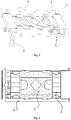
Fig. 1 illustrates a top view of a foldable hanger in a use state provided inembodiment 1 of the invention. -
Fig. 2 illustrates a front view of the fold hanger as shown inFig. 1 in a use state. -
Fig. 3 illustrates a three-dimensional view of the fold hanger as shown inFig. 1 in a use state. -
Fig. 4 illustrates an upward view of the fold hanger as shown inFig. 1 in a storing state. -
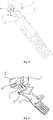
Fig. 5 illustrates a structure diagram of a cooperation between folding feet and a inclined wedge mechanism of the foldable hanger as shown inFig. 1 . -
Fig. 6 illustrates a structure diagram (from another angle) of the cooperation between the folding feet and the inclined wedge mechanism as shown inFig. 5 . -
Fig. 7 illustrates a three-dimensional view of a foldable hanger in a use state provided in another embodiment. -
Fig. 8 illustrates a structure diagram of a cooperation between the folding feet and a gear drive mechanism of the foldable hanger provided in another embodiment. - 1. hanger body; 2. folding feet; 3. hanging and drying rod; 4. support rod; 5. fixed clothes drying board; 6. sliding block; 7. guide part; 8. linkage part; 9. movable clothes drying board; 10. gear; 11. rack; 12. dual gear.
- The technical solutions of the invention are described clearly and completely below in combination with the drawings. Apparently, the described embodiments are merely a part of the embodiments of the invention, not all of the embodiments. All other embodiments obtained by those skilled in the art based on the embodiments in the invention without creative work shall fall within a scope of protection of the invention.
- In the descriptions of the invention, it is to be noted that orientation or position relationships indicated by terms "upper", "lower", "vertical", "horizontal" and the like are orientation or position relationships shown in the drawings, are adopted not to indicate or imply that indicated devices or members must be in specific orientations or structured and operated in specific orientations but only to conveniently describe the invention and simplify descriptions. In addition, the terms "first" and "second" are used for descriptive purposes only and are not to be construed as indicating or implying relative importance.
- In the description of the invention, it is to be noted that unless otherwise definitely specified and limited, terms "mount" and "connect" should be broadly understood. For example, the terms refer to fixed connection and also refer to detachable connection or integrated connection. The terms refer to mechanical connection or electrical connection. The terms refer to direct mutual connection, also refer to indirect connection through a medium and refer to communication in two members. For those skilled in the art, specific meanings of these terms in the invention can be understood according to a specific condition.
- In addition, the technical features involved in different implementation modes of the invention described below can be combined without conflicts.
- As shown in
Fig. 1 to Fig. 6 , a foldable hanger provided by the embodiment includes ahanger body 1, andfolding feet 2 and a hanging and drying member movably connected to thehanger body 1, and a linkage mechanism disposed between thefolding feet 2 and the hanging and drying member; thefolding feet 2 have a supporting state after unfolding and a storing state after folding; the hanging and drying member has a hanging and drying state distant from thehanger body 1 and a resetting state close to thehanger body 1; a change of a state of thefolding feet 2 drives, through the linkage mechanism, a state of the hanging and drying member to change; the supporting state corresponds to the hanging and drying state, and the storing state corresponds to the resetting state. Therefore, a setting of the linkage mechanism can make the hanging and drying member away from or close to thehanger body 1 when thefolding feet 2 are unfolded or folded, so that no matter in a process of packaging and transportation or in a use process of users, the hanger body can be unfolded or folded in one step without separately operating the feet and the hanging and drying member, which reduces operation steps, saves operation time, improves a user experience by completing an operation at one time, and makes a packaging, installation and storage process easier and more convenient. - In some embodiments, the
hanger body 1 is rectangular, thefolding feet 2 are hinged on thehanger body 1, and the hanging and drying member is in sliding fit with a slide rail on thehanger body 1 through its sliding part; thehanger body 1 is provided with the slide rail formed by a cavity, and the hanging and drying member includes the sliding part and a hanging and dryingrod 3 disposed on the sliding part, the sliding part being asupport rod 4 disposed in the cavity and capable of reciprocating sliding along the cavity, and the hanging and drying member being a hanging and dryingstate 3 connected to a free end of thesupport rod 4. In such a manner, when the foldable hanger is packaged or stored, the hanging and drying member slides close to thehanger body 1 while the user rotates and folds thefolding feet 2, so that the hanging and drying member also moves to the resetting state while the feet are folded to the storing state; when the foldable hanger is installed or used, the hanging and drying member slides away from thehanger body 1 while the user rotates to unfold thefolding feet 2, so that the hanging and drying member also moves to the hanging and drying state while the feet are unfolded to the supporting state. - There is a pair of
folding feet 2 disposed at a bottom of thehanger body 1, so that they can be folded and stored under thehanger body 1. There are two cavities, which are disposed along a width direction ofhanger body 1 respectively and located at two ends ofhanger body 1. There are two pairs ofsupport rods 4, each pair ofsupport rods 4 extend into a same end of two cavities respectively, and there is a hanging and dryingrod 3 connected between free ends of each pair ofsupport rods 4. Two hanging and dryingrods 3 are respectively located at two sides of thehanger body 1, and can extend away from thehanger body 1 or retract back towards the direction close to thehanger body 1. - An inner wall of the cavity is provided with a clamping slot. The clamping slot is in tabling fit with an elastic clamping pin on an outer wall of the
support rod 4 to prevent thesupport rod 4 from falling out of the cavity. - The
hanger body 1 is also disposed with a fixedclothes drying board 5, and two hanging and dryingrods 3 are respectively located at two sides of the fixedclothes drying board 5. When the hanging and dryingrod 3 is in the resetting state, it is disposed close to the two sides of the fixedclothes drying board 5. The fixedclothes drying board 5 is provided with a plurality of through holes. - In some embodiments, as shown in
Fig. 5 to Fig. 6 , the linkage mechanism is a inclined wedge mechanism, and the inclined wedge mechanism includes alinkage part 8 disposed on thefolding feet 2 and a slidingblock 6 disposed on thehanger body 1. An end portion of one end of thesupport rod 4 extended into the cavity is a bevel and the slidingblock 6 has a bevel cooperated with the bevel, so that the slidingblock 6 and the end portion of thesupport rod 4 form a bevel fit. The slidingblock 6 is also provided with a guide part 7 cooperating with a guide structure disposed onhanger body 1; in some embodiments, the guide structure is a through hole disposed on a bottom surface ofhanger body 1, and an axial direction of the through hole is perpendicular to a sliding direction ofsupport rod 4; the guide part 7 is a guide block disposed together with the slidingblock 6, and the guide block, a contour of which adapts to a contour of the through hole, extends out of the through hole. When thelinkage part 8 of thefolding feet 2 pushes the guide block to move along the through hole toward a direction away from the bottom surface of thehanger body 1, the slidingblock 6 pushes against the end portion of thesupport rod 4 through the bevel, so that thesupport rod 4 slides out of the cavity, and the hanging and dryingrod 3 extends out to the hanging and drying state. - The
linkage part 8 is an end portion of a hinged end of thefolding feet 2. When thefolding feet 2 are fully unfolded, its end face pushes against the guide part 7 to drive thesupport rod 4 to slide. - The inclined wedge mechanism further includes an elastic reset structure disposed on the hanging and drying member. The elastic reset structure is an elastic compression spring disposed between the cavity and the
support rod 4. When thesupport rod 4 moves toward a direction extending out of the cavity, the elastic compression spring compresses; and when thefolding feet 2 fold to the storing state, its hinged end gradually eliminates a push against a guide hole, and thesupport rod 4 retracts into the cavity under a first resetting force of the elastic compression spring. The elastic reset structure is helpful for the hanging and dryingrod 3 to move to the resetting state with less effort and ease. - In some embodiments, a first radial lug boss extending outward is disposed on the
support rod 4, an opening of the cavity is provided with a second radial lug boss extending inwards to prevent thesupport rod 4 from falling out, and the elastic compression spring is disposed between the first raidal lug boss and the second radial lug boss. - Some embodiments of the present embodiment also provides a heating device, which includes a heating body and the foldable hanger detachably connected to the heating body. The foldable hanger is detachably mounted on the heating body, which is convenient to dry clothes; during storage, the foldable hanger is folded and stored directly by one-step operation, which is easy and convenient.
- In some embodiments, the heating device is an electric heater, the heating body is radiating fins, the
folding feet 2 of the foldable hanger are clamped above the radiating fins, the hanger body is above the radiating fins, and the hanging and drying member is at two sides of the radiating fins. - As an alternative implementation mode of
embodiment 1, as shown inFig. 7 and Fig. 8 , the hanging and drying member is a pair of movable clothes drying boards (9) and the hanging and drying rod (3) disposed on the outside of each movable clothes drying board (9); the movable clothes drying board (9) is in sliding fit with the slide rail on the hanger body (1) through its sliding part; the sliding part is sliding slots disposed at two ends of the movable clothes drying board (9), and the slide way is a plurality of convex block located at two ends of the hanger body (1) in a length direction; the pair of movable clothes drying boards (9) can close to or move away from each other through a sliding of the sliding slot along the convex block. The linkage mechanism is a gear drive mechanism. The gear drive mechanism includes a gear (10) disposed on the hinged end of the folding feet (2), a rack (11) disposed on the side wall of sliding part, and a dual gear (12) meshed with the gear (10) and the rack (11). The gear (10) on the folding feet (2) is meshed with a small gear (10) of the dual gear (12), and a big gear (10) of the dual gear (12) is meshed with the rack (11) on a side wall of the sliding part. The folding feet (2) rotate or the sliding part slides, so that the gear (10) or the rack (11) is driven to drive the dual gear (12) to rotate, thus realizing a sliding of the sliding part or a rotation of the folding feet (2), at this point, a rotation plane of the folding feet (2) is parallel to a sliding direction of the movable clothes drying board (9). - As an alternative implementation mode of
embodiment 1, as shown inFig. 8 , the linkage mechanism is a gear (10) transmission mechanism. The gear transmission mechanism includes the gear (10) disposed on the hinged end of the folding feet (2), the rack (11) disposed on the side wall of the support rod (4), and the dual gear (12) meshed with the gear (10) and the rack (11) respectively. The gear (10) on the folding feet (2) is meshed with the small gear (10) of the dual gear (12), and the big gear (10) of the dual gear (12) is meshed with the rack (11) on the side wall of the sliding part. The folding feet (2) rotate or the sliding part slides, so that the gear (10) or the rack (11) is driven to drive the dual gear (12) to rotate, thus realizing the sliding of the sliding part or the rotation of the folding feet (2), at this point, the rotation plane of the folding feet (2) is parallel to the sliding direction of the support rod (4). - As an alternative implementation mode of
embodiment 1, the support rod is provided with a groove extending axially, and the elastic compression spring is disposed in the groove. One end of the elastic compression spring is abutted against an inner end of the groove, and the other end of the elastic compression spring is abutted against the second radial lug boss extending inward, which is disposed at the opening of the cavity to prevent the support rod from falling out. - As an alternative implementation mode of
embodiment 1, the elastic reset structure is disposed between the folding feet and the hanger body. The elastic reset structure is the elastic compression spring which applies the second resetting force to move the folding feet toward the storing state. When the folding feet rotate to the supporting state, its linkage part pushes against the sliding block, and the sliding part of the hanging and drying member moves to the hanging and drying state; when the hanging and drying member is pushed to move to the resetting state, its sliding part pushes against the sliding block, and the folding feet rotates to the storing state under an action of the second resetting force. - As an alternative implementation mode of
embodiment 1, the guide structure is a guide bar disposed on the hanger body and perpendicular to the slide rail. The sliding block has a guide groove matching with the guide bar. The sliding block is disposed in the hanger body, and reciprocating moves along the guide bar to push the sliding part to reciprocating slide. - As an alternative implementation mode of
embodiment 1, the linkage part is a protrusion on the folding feet. When the folding feet are unfolded, the protrusion pushes against the guide block. - As an alternative implementation mode of
embodiment 1, the heating device is water heater. - It is apparent that the abovementioned embodiments are only examples for clear description and not intended to limit the implementation modes. Those of ordinary skill in the art further make variations or modifications of other different forms on a basis of the above descriptions. It is unnecessary and impossible to exhaust all of the implementation modes herein. Apparent variations or modifications derived therefrom also fall within a scope of protection of the invention.
Claims (16)
- A foldable hanger, comprising:a hanger body (1);folding feet (2) movably connected to the hanger body (1) and having a supporting state after unfolding and a storing state after folding;a hanging and drying member movably connected to the hanger body (1) and having a hanging and drying state distant from the hanger body (1) and a resetting state close to the hanger body (1); anda linkage mechanism disposed between the folding feet (2) and the hanging and drying member; a change of a state of any one of the folding feet (2) and the hanging and drying member drives, through the linkage mechanism, a state of the other of the folding feet (2) and the hanging and drying member to change; wherein the supporting state corresponds to the hanging and drying state, and the storing state corresponds to the resetting state.
- The foldable hanger as claimed in claim 1, wherein the folding feet (2) are hinged on the hanger body (1); the hanging and drying member has a sliding part which is in sliding fit with a slide rail disposed on the hanger body (1); the linkage mechanism converts a reciprocating rotation of the folding feet (2) to a reciprocating sliding of the hanging and drying member or converts a reciprocating sliding of the hanging and drying member to a reciprocating rotation of the folding feet (2).
- The foldable hanger as claimed in claim 2, wherein the linkage mechanism is an inclined wedge mechanism.
- The foldable hanger as claimed in claim 3, wherein the inclined wedge mechanism comprises a linkage part (8) disposed on the folding feet (2) and a sliding block (6) disposed on the hanger body (1); the sliding block (6) is in bevel fit with the sliding part; a guide part (7) cooperating with a guide structure disposed on the hanger body (1) is disposed on the sliding block (6); the linkage part (8) pushes the sliding block (6) to move along the guide structure, and the sliding block (6) drives the sliding part to move along the slide rail, so that the hanging and drying member moves to the hanging and drying state; on the contrary, the hanging and drying member drives the folding feet (2) to move through the sliding part, the sliding block (6) and the linkage part (8).
- The foldable hanger as claimed in claim 4, wherein the guide structure is a through hole disposed at a bottom of the hanger body (1), the guide part (7) is adapted to extend into the through hole, and the linkage part (8) pushes the guide part (7) to move along the through hole.
- The foldable hanger as claimed in claim 4, wherein the linkage part (8) is a hinged end part of the folding feet (2).
- The foldable hanger as claimed in claim 4, wherein the inclined wedge mechanism further comprises an elastic reset structure acting on the hanging and drying member and/or the folding feet (2); the elastic reset structure applies a first resetting force to move the hanging and drying member toward the resetting state; and/or, the elastic reset structure applies a second resetting force to move the folding feet (2) toward the storing state.
- The foldable hanger as claimed in claim 2, wherein the linkage mechanism is a gear transmission mechanism.
- The foldable hanger as claimed in claim 8, wherein the gear transmission mechanism comprises a gear (10) disposed on a hinged end of the folding feet (2), a rack (11) disposed on the sliding part, and a dual gear (12) meshed with the gear (10) and the rack (11) respectively.
- The foldable hanger as claimed in any one of claims 2 to 9, wherein the sliding part is a support rod (4) in sliding fit with the slide rail.
- The foldable hanger as claimed in claim 10, wherein the hanging and drying member further comprises a hanging and drying rod (3) connected to a free end of the support rod (4).
- The foldable hanger as claimed in claim 11, wherein the hanger body (1) is also provided with a fixed clothes drying board (5), and the hanging and drying rod (3) is on a side of the fixed clothes drying board (5).
- The foldable hanger as claimed in any one of claims 2 to 9, wherein the sliding part is a sliding slot in sliding fit with the slide rail.
- The foldable hanger as claimed in claim 13, wherein the hanging and drying member further comprises a movable clothes drying board (9), and the sliding slot is disposed on the movable clothes drying board (9).
- A heating device, comprising a heating body and the foldable hanger as claimed in any one of claims 1 to 14, wherein the foldable hanger is detachably connected to the heating body.
- The heating device as claimed in claim 15, wherein the heating device is an electric heater.
Applications Claiming Priority (2)
| Application Number | Priority Date | Filing Date | Title |
|---|---|---|---|
| CN201810404740.XA CN108360225B (en) | 2018-04-28 | 2018-04-28 | Folding clothes hanger and heating equipment |
| PCT/CN2018/113085 WO2019205550A1 (en) | 2018-04-28 | 2018-10-31 | Foldable hanger and heating device |
Publications (3)
| Publication Number | Publication Date |
|---|---|
| EP3789532A1 true EP3789532A1 (en) | 2021-03-10 |
| EP3789532A4 EP3789532A4 (en) | 2021-03-10 |
| EP3789532B1 EP3789532B1 (en) | 2023-10-04 |
Family
ID=63009670
Family Applications (1)
| Application Number | Title | Priority Date | Filing Date |
|---|---|---|---|
| EP18915860.3A Active EP3789532B1 (en) | 2018-04-28 | 2018-10-31 | Foldable hanger and heating device |
Country Status (3)
| Country | Link |
|---|---|
| EP (1) | EP3789532B1 (en) |
| CN (1) | CN108360225B (en) |
| WO (1) | WO2019205550A1 (en) |
Families Citing this family (6)
| Publication number | Priority date | Publication date | Assignee | Title |
|---|---|---|---|---|
| CN108360225B (en) * | 2018-04-28 | 2019-10-01 | 珠海格力电器股份有限公司 | Folding clothes hanger and heating equipment |
| CN109234988B (en) * | 2018-12-07 | 2023-10-10 | 怀化学院 | clothes drying rack |
| CN110629472B (en) * | 2019-10-14 | 2023-05-16 | 珠海格力电器股份有限公司 | Clothes collection rack and intelligent clothes drying device |
| CN113100619A (en) * | 2021-03-06 | 2021-07-13 | 宿州市怡美家居用品有限公司 | Adjustable telescopic clothes hanger |
| CN114438756B (en) * | 2022-01-29 | 2023-06-30 | 安徽国悦电器科技股份有限公司 | Clothes airing support for warmer |
| CN114484581B (en) * | 2022-04-01 | 2024-07-09 | 武汉市江楚开物科技有限公司 | Multifunctional hanging rack for skirting line warmer |
Family Cites Families (9)
| Publication number | Priority date | Publication date | Assignee | Title |
|---|---|---|---|---|
| KR101025092B1 (en) * | 2009-01-16 | 2011-03-25 | 이종민 | Folding laundry drying rack which is available for interlocking movement |
| CN203021806U (en) * | 2012-12-20 | 2013-06-26 | 格力电器(中山)小家电制造有限公司 | Foldable clothes hanger and electric heater with same |
| CN203295851U (en) * | 2013-05-29 | 2013-11-20 | 珠海格力电器股份有限公司 | Folding clothes hanger for electric heater and electric heater |
| CN107405768A (en) * | 2015-02-03 | 2017-11-28 | 亲和工具工程有限公司 | With can Automatic-expanding leg tool rack |
| CN205368812U (en) * | 2016-01-29 | 2016-07-06 | 宁波先锋电器制造有限公司 | Modified is folded airer and is used this airer's room heater |
| CN106073192B (en) * | 2016-08-04 | 2019-07-16 | 陈云 | Rotary folding table |
| CN206166215U (en) * | 2016-08-04 | 2017-05-17 | 陈云 | Rotatory folding table |
| CN108360225B (en) * | 2018-04-28 | 2019-10-01 | 珠海格力电器股份有限公司 | Folding clothes hanger and heating equipment |
| CN208167340U (en) * | 2018-04-28 | 2018-11-30 | 珠海格力电器股份有限公司 | Folding clothes hanger and heating equipment |
-
2018
- 2018-04-28 CN CN201810404740.XA patent/CN108360225B/en active Active
- 2018-10-31 EP EP18915860.3A patent/EP3789532B1/en active Active
- 2018-10-31 WO PCT/CN2018/113085 patent/WO2019205550A1/en not_active Ceased
Also Published As
| Publication number | Publication date |
|---|---|
| EP3789532A4 (en) | 2021-03-10 |
| CN108360225B (en) | 2019-10-01 |
| WO2019205550A1 (en) | 2019-10-31 |
| CN108360225A (en) | 2018-08-03 |
| EP3789532B1 (en) | 2023-10-04 |
Similar Documents
| Publication | Publication Date | Title |
|---|---|---|
| EP3789532B1 (en) | Foldable hanger and heating device | |
| JP3095277U (en) | Automatic folding running machine | |
| US12222062B2 (en) | Foldable support | |
| CN210433277U (en) | Portable plastic clothes hanger | |
| CN112273878B (en) | Intelligent telescopic folding storage clothes rack | |
| CN208167340U (en) | Folding clothes hanger and heating equipment | |
| CN211407968U (en) | Folding kettle | |
| KR200332501Y1 (en) | Wash drying shelf with auxiliary hanger | |
| CN117502859A (en) | Foldable support, foldable container and foldable bed | |
| CN214401092U (en) | Folding mechanism and floor clothes hanger | |
| CN108951034A (en) | Clothes hanger subassembly of room heater and room heater that has this clothes hanger subassembly | |
| CN111058262A (en) | Ironing equipment | |
| CN210643611U (en) | Folding clothes hanger | |
| CN212465431U (en) | Sliding rail assembly | |
| CN220790657U (en) | Suspended ceiling installing support folder | |
| CN108589217B (en) | Clothes hanger beta structure, clothes hanger and dryer | |
| CN208933702U (en) | Wardrobe of clothes dryer and clothes dryer with same | |
| CN215488494U (en) | A new type of projection equipment | |
| CN208630440U (en) | Vehicle and its cup holder device | |
| CN209456770U (en) | Ironing equipment | |
| CN218508080U (en) | Auxiliary airing rod unfolding structure for clothes airing rack | |
| CN223316957U (en) | clothes dryer | |
| CN219908271U (en) | Clothes airing rod | |
| CN215328891U (en) | Folding clothes hanger | |
| CN214459009U (en) | Telescopic portable clothes hanger |
Legal Events
| Date | Code | Title | Description |
|---|---|---|---|
| STAA | Information on the status of an ep patent application or granted ep patent |
Free format text: STATUS: THE INTERNATIONAL PUBLICATION HAS BEEN MADE |
|
| PUAI | Public reference made under article 153(3) epc to a published international application that has entered the european phase |
Free format text: ORIGINAL CODE: 0009012 |
|
| STAA | Information on the status of an ep patent application or granted ep patent |
Free format text: STATUS: REQUEST FOR EXAMINATION WAS MADE |
|
| 17P | Request for examination filed |
Effective date: 20201014 |
|
| A4 | Supplementary search report drawn up and despatched |
Effective date: 20210202 |
|
| AK | Designated contracting states |
Kind code of ref document: A1 Designated state(s): AL AT BE BG CH CY CZ DE DK EE ES FI FR GB GR HR HU IE IS IT LI LT LU LV MC MK MT NL NO PL PT RO RS SE SI SK SM TR |
|
| AX | Request for extension of the european patent |
Extension state: BA ME |
|
| DAV | Request for validation of the european patent (deleted) | ||
| DAX | Request for extension of the european patent (deleted) | ||
| RIC1 | Information provided on ipc code assigned before grant |
Ipc: D06F 57/06 20060101ALN20230419BHEP Ipc: A47G 25/06 20060101ALN20230419BHEP Ipc: F24D 19/00 20060101ALI20230419BHEP Ipc: D06F 57/12 20060101ALI20230419BHEP Ipc: D06F 57/08 20060101AFI20230419BHEP |
|
| GRAP | Despatch of communication of intention to grant a patent |
Free format text: ORIGINAL CODE: EPIDOSNIGR1 |
|
| STAA | Information on the status of an ep patent application or granted ep patent |
Free format text: STATUS: GRANT OF PATENT IS INTENDED |
|
| RIC1 | Information provided on ipc code assigned before grant |
Ipc: D06F 57/06 20060101ALN20230425BHEP Ipc: A47G 25/06 20060101ALN20230425BHEP Ipc: F24D 19/00 20060101ALI20230425BHEP Ipc: D06F 57/12 20060101ALI20230425BHEP Ipc: D06F 57/08 20060101AFI20230425BHEP |
|
| RIC1 | Information provided on ipc code assigned before grant |
Ipc: D06F 57/06 20060101ALN20230509BHEP Ipc: A47G 25/06 20060101ALN20230509BHEP Ipc: F24D 19/00 20060101ALI20230509BHEP Ipc: D06F 57/12 20060101ALI20230509BHEP Ipc: D06F 57/08 20060101AFI20230509BHEP |
|
| INTG | Intention to grant announced |
Effective date: 20230531 |
|
| P01 | Opt-out of the competence of the unified patent court (upc) registered |
Effective date: 20230530 |
|
| GRAS | Grant fee paid |
Free format text: ORIGINAL CODE: EPIDOSNIGR3 |
|
| GRAA | (expected) grant |
Free format text: ORIGINAL CODE: 0009210 |
|
| STAA | Information on the status of an ep patent application or granted ep patent |
Free format text: STATUS: THE PATENT HAS BEEN GRANTED |
|
| AK | Designated contracting states |
Kind code of ref document: B1 Designated state(s): AL AT BE BG CH CY CZ DE DK EE ES FI FR GB GR HR HU IE IS IT LI LT LU LV MC MK MT NL NO PL PT RO RS SE SI SK SM TR |
|
| REG | Reference to a national code |
Ref country code: GB Ref legal event code: FG4D |
|
| REG | Reference to a national code |
Ref country code: CH Ref legal event code: EP |
|
| REG | Reference to a national code |
Ref country code: IE Ref legal event code: FG4D |
|
| REG | Reference to a national code |
Ref country code: DE Ref legal event code: R096 Ref document number: 602018058960 Country of ref document: DE |
|
| REG | Reference to a national code |
Ref country code: LT Ref legal event code: MG9D |
|
| REG | Reference to a national code |
Ref country code: NL Ref legal event code: MP Effective date: 20231004 |
|
| REG | Reference to a national code |
Ref country code: AT Ref legal event code: MK05 Ref document number: 1617872 Country of ref document: AT Kind code of ref document: T Effective date: 20231004 |
|
| PG25 | Lapsed in a contracting state [announced via postgrant information from national office to epo] |
Ref country code: NL Free format text: LAPSE BECAUSE OF FAILURE TO SUBMIT A TRANSLATION OF THE DESCRIPTION OR TO PAY THE FEE WITHIN THE PRESCRIBED TIME-LIMIT Effective date: 20231004 |
|
| PG25 | Lapsed in a contracting state [announced via postgrant information from national office to epo] |
Ref country code: GR Free format text: LAPSE BECAUSE OF FAILURE TO SUBMIT A TRANSLATION OF THE DESCRIPTION OR TO PAY THE FEE WITHIN THE PRESCRIBED TIME-LIMIT Effective date: 20240105 |
|
| PG25 | Lapsed in a contracting state [announced via postgrant information from national office to epo] |
Ref country code: IS Free format text: LAPSE BECAUSE OF FAILURE TO SUBMIT A TRANSLATION OF THE DESCRIPTION OR TO PAY THE FEE WITHIN THE PRESCRIBED TIME-LIMIT Effective date: 20240204 |
|
| PG25 | Lapsed in a contracting state [announced via postgrant information from national office to epo] |
Ref country code: LT Free format text: LAPSE BECAUSE OF FAILURE TO SUBMIT A TRANSLATION OF THE DESCRIPTION OR TO PAY THE FEE WITHIN THE PRESCRIBED TIME-LIMIT Effective date: 20231004 |
|
| PG25 | Lapsed in a contracting state [announced via postgrant information from national office to epo] |
Ref country code: AT Free format text: LAPSE BECAUSE OF FAILURE TO SUBMIT A TRANSLATION OF THE DESCRIPTION OR TO PAY THE FEE WITHIN THE PRESCRIBED TIME-LIMIT Effective date: 20231004 |
|
| PG25 | Lapsed in a contracting state [announced via postgrant information from national office to epo] |
Ref country code: ES Free format text: LAPSE BECAUSE OF FAILURE TO SUBMIT A TRANSLATION OF THE DESCRIPTION OR TO PAY THE FEE WITHIN THE PRESCRIBED TIME-LIMIT Effective date: 20231004 |
|
| PG25 | Lapsed in a contracting state [announced via postgrant information from national office to epo] |
Ref country code: LT Free format text: LAPSE BECAUSE OF FAILURE TO SUBMIT A TRANSLATION OF THE DESCRIPTION OR TO PAY THE FEE WITHIN THE PRESCRIBED TIME-LIMIT Effective date: 20231004 Ref country code: IS Free format text: LAPSE BECAUSE OF FAILURE TO SUBMIT A TRANSLATION OF THE DESCRIPTION OR TO PAY THE FEE WITHIN THE PRESCRIBED TIME-LIMIT Effective date: 20240204 Ref country code: GR Free format text: LAPSE BECAUSE OF FAILURE TO SUBMIT A TRANSLATION OF THE DESCRIPTION OR TO PAY THE FEE WITHIN THE PRESCRIBED TIME-LIMIT Effective date: 20240105 Ref country code: ES Free format text: LAPSE BECAUSE OF FAILURE TO SUBMIT A TRANSLATION OF THE DESCRIPTION OR TO PAY THE FEE WITHIN THE PRESCRIBED TIME-LIMIT Effective date: 20231004 Ref country code: BG Free format text: LAPSE BECAUSE OF FAILURE TO SUBMIT A TRANSLATION OF THE DESCRIPTION OR TO PAY THE FEE WITHIN THE PRESCRIBED TIME-LIMIT Effective date: 20240104 Ref country code: AT Free format text: LAPSE BECAUSE OF FAILURE TO SUBMIT A TRANSLATION OF THE DESCRIPTION OR TO PAY THE FEE WITHIN THE PRESCRIBED TIME-LIMIT Effective date: 20231004 Ref country code: PT Free format text: LAPSE BECAUSE OF FAILURE TO SUBMIT A TRANSLATION OF THE DESCRIPTION OR TO PAY THE FEE WITHIN THE PRESCRIBED TIME-LIMIT Effective date: 20240205 |
|
| PG25 | Lapsed in a contracting state [announced via postgrant information from national office to epo] |
Ref country code: SE Free format text: LAPSE BECAUSE OF FAILURE TO SUBMIT A TRANSLATION OF THE DESCRIPTION OR TO PAY THE FEE WITHIN THE PRESCRIBED TIME-LIMIT Effective date: 20231004 Ref country code: RS Free format text: LAPSE BECAUSE OF FAILURE TO SUBMIT A TRANSLATION OF THE DESCRIPTION OR TO PAY THE FEE WITHIN THE PRESCRIBED TIME-LIMIT Effective date: 20231004 Ref country code: PL Free format text: LAPSE BECAUSE OF FAILURE TO SUBMIT A TRANSLATION OF THE DESCRIPTION OR TO PAY THE FEE WITHIN THE PRESCRIBED TIME-LIMIT Effective date: 20231004 Ref country code: NO Free format text: LAPSE BECAUSE OF FAILURE TO SUBMIT A TRANSLATION OF THE DESCRIPTION OR TO PAY THE FEE WITHIN THE PRESCRIBED TIME-LIMIT Effective date: 20240104 Ref country code: LV Free format text: LAPSE BECAUSE OF FAILURE TO SUBMIT A TRANSLATION OF THE DESCRIPTION OR TO PAY THE FEE WITHIN THE PRESCRIBED TIME-LIMIT Effective date: 20231004 Ref country code: HR Free format text: LAPSE BECAUSE OF FAILURE TO SUBMIT A TRANSLATION OF THE DESCRIPTION OR TO PAY THE FEE WITHIN THE PRESCRIBED TIME-LIMIT Effective date: 20231004 |
|
| REG | Reference to a national code |
Ref country code: CH Ref legal event code: PL |
|
| REG | Reference to a national code |
Ref country code: BE Ref legal event code: MM Effective date: 20231031 |
|
| PG25 | Lapsed in a contracting state [announced via postgrant information from national office to epo] |
Ref country code: LU Free format text: LAPSE BECAUSE OF NON-PAYMENT OF DUE FEES Effective date: 20231031 |
|
| PG25 | Lapsed in a contracting state [announced via postgrant information from national office to epo] |
Ref country code: LU Free format text: LAPSE BECAUSE OF NON-PAYMENT OF DUE FEES Effective date: 20231031 |
|
| REG | Reference to a national code |
Ref country code: DE Ref legal event code: R097 Ref document number: 602018058960 Country of ref document: DE |
|
| PG25 | Lapsed in a contracting state [announced via postgrant information from national office to epo] |
Ref country code: DK Free format text: LAPSE BECAUSE OF FAILURE TO SUBMIT A TRANSLATION OF THE DESCRIPTION OR TO PAY THE FEE WITHIN THE PRESCRIBED TIME-LIMIT Effective date: 20231004 |
|
| PG25 | Lapsed in a contracting state [announced via postgrant information from national office to epo] |
Ref country code: CH Free format text: LAPSE BECAUSE OF NON-PAYMENT OF DUE FEES Effective date: 20231031 |
|
| PG25 | Lapsed in a contracting state [announced via postgrant information from national office to epo] |
Ref country code: CZ Free format text: LAPSE BECAUSE OF FAILURE TO SUBMIT A TRANSLATION OF THE DESCRIPTION OR TO PAY THE FEE WITHIN THE PRESCRIBED TIME-LIMIT Effective date: 20231004 |
|
| PG25 | Lapsed in a contracting state [announced via postgrant information from national office to epo] |
Ref country code: SK Free format text: LAPSE BECAUSE OF FAILURE TO SUBMIT A TRANSLATION OF THE DESCRIPTION OR TO PAY THE FEE WITHIN THE PRESCRIBED TIME-LIMIT Effective date: 20231004 |
|
| PG25 | Lapsed in a contracting state [announced via postgrant information from national office to epo] |
Ref country code: SM Free format text: LAPSE BECAUSE OF FAILURE TO SUBMIT A TRANSLATION OF THE DESCRIPTION OR TO PAY THE FEE WITHIN THE PRESCRIBED TIME-LIMIT Effective date: 20231004 Ref country code: SK Free format text: LAPSE BECAUSE OF FAILURE TO SUBMIT A TRANSLATION OF THE DESCRIPTION OR TO PAY THE FEE WITHIN THE PRESCRIBED TIME-LIMIT Effective date: 20231004 Ref country code: RO Free format text: LAPSE BECAUSE OF FAILURE TO SUBMIT A TRANSLATION OF THE DESCRIPTION OR TO PAY THE FEE WITHIN THE PRESCRIBED TIME-LIMIT Effective date: 20231004 Ref country code: IT Free format text: LAPSE BECAUSE OF FAILURE TO SUBMIT A TRANSLATION OF THE DESCRIPTION OR TO PAY THE FEE WITHIN THE PRESCRIBED TIME-LIMIT Effective date: 20231004 Ref country code: EE Free format text: LAPSE BECAUSE OF FAILURE TO SUBMIT A TRANSLATION OF THE DESCRIPTION OR TO PAY THE FEE WITHIN THE PRESCRIBED TIME-LIMIT Effective date: 20231004 Ref country code: DK Free format text: LAPSE BECAUSE OF FAILURE TO SUBMIT A TRANSLATION OF THE DESCRIPTION OR TO PAY THE FEE WITHIN THE PRESCRIBED TIME-LIMIT Effective date: 20231004 Ref country code: CZ Free format text: LAPSE BECAUSE OF FAILURE TO SUBMIT A TRANSLATION OF THE DESCRIPTION OR TO PAY THE FEE WITHIN THE PRESCRIBED TIME-LIMIT Effective date: 20231004 Ref country code: CH Free format text: LAPSE BECAUSE OF NON-PAYMENT OF DUE FEES Effective date: 20231031 |
|
| PLBE | No opposition filed within time limit |
Free format text: ORIGINAL CODE: 0009261 |
|
| STAA | Information on the status of an ep patent application or granted ep patent |
Free format text: STATUS: NO OPPOSITION FILED WITHIN TIME LIMIT |
|
| PG25 | Lapsed in a contracting state [announced via postgrant information from national office to epo] |
Ref country code: MC Free format text: LAPSE BECAUSE OF FAILURE TO SUBMIT A TRANSLATION OF THE DESCRIPTION OR TO PAY THE FEE WITHIN THE PRESCRIBED TIME-LIMIT Effective date: 20231004 |
|
| PG25 | Lapsed in a contracting state [announced via postgrant information from national office to epo] |
Ref country code: MC Free format text: LAPSE BECAUSE OF FAILURE TO SUBMIT A TRANSLATION OF THE DESCRIPTION OR TO PAY THE FEE WITHIN THE PRESCRIBED TIME-LIMIT Effective date: 20231004 Ref country code: BE Free format text: LAPSE BECAUSE OF NON-PAYMENT OF DUE FEES Effective date: 20231031 |
|
| 26N | No opposition filed |
Effective date: 20240705 |
|
| PG25 | Lapsed in a contracting state [announced via postgrant information from national office to epo] |
Ref country code: IE Free format text: LAPSE BECAUSE OF NON-PAYMENT OF DUE FEES Effective date: 20231031 |
|
| PG25 | Lapsed in a contracting state [announced via postgrant information from national office to epo] |
Ref country code: FR Free format text: LAPSE BECAUSE OF NON-PAYMENT OF DUE FEES Effective date: 20231204 |
|
| PG25 | Lapsed in a contracting state [announced via postgrant information from national office to epo] |
Ref country code: SI Free format text: LAPSE BECAUSE OF FAILURE TO SUBMIT A TRANSLATION OF THE DESCRIPTION OR TO PAY THE FEE WITHIN THE PRESCRIBED TIME-LIMIT Effective date: 20231004 |
|
| PG25 | Lapsed in a contracting state [announced via postgrant information from national office to epo] |
Ref country code: SI Free format text: LAPSE BECAUSE OF FAILURE TO SUBMIT A TRANSLATION OF THE DESCRIPTION OR TO PAY THE FEE WITHIN THE PRESCRIBED TIME-LIMIT Effective date: 20231004 Ref country code: IE Free format text: LAPSE BECAUSE OF NON-PAYMENT OF DUE FEES Effective date: 20231031 Ref country code: FR Free format text: LAPSE BECAUSE OF NON-PAYMENT OF DUE FEES Effective date: 20231204 |
|
| PG25 | Lapsed in a contracting state [announced via postgrant information from national office to epo] |
Ref country code: FI Free format text: LAPSE BECAUSE OF FAILURE TO SUBMIT A TRANSLATION OF THE DESCRIPTION OR TO PAY THE FEE WITHIN THE PRESCRIBED TIME-LIMIT Effective date: 20231004 |
|
| PG25 | Lapsed in a contracting state [announced via postgrant information from national office to epo] |
Ref country code: CY Free format text: LAPSE BECAUSE OF FAILURE TO SUBMIT A TRANSLATION OF THE DESCRIPTION OR TO PAY THE FEE WITHIN THE PRESCRIBED TIME-LIMIT; INVALID AB INITIO Effective date: 20181031 |
|
| PG25 | Lapsed in a contracting state [announced via postgrant information from national office to epo] |
Ref country code: HU Free format text: LAPSE BECAUSE OF FAILURE TO SUBMIT A TRANSLATION OF THE DESCRIPTION OR TO PAY THE FEE WITHIN THE PRESCRIBED TIME-LIMIT; INVALID AB INITIO Effective date: 20181031 |
|
| PGFP | Annual fee paid to national office [announced via postgrant information from national office to epo] |
Ref country code: GB Payment date: 20250908 Year of fee payment: 8 |
|
| PG25 | Lapsed in a contracting state [announced via postgrant information from national office to epo] |
Ref country code: TR Free format text: LAPSE BECAUSE OF FAILURE TO SUBMIT A TRANSLATION OF THE DESCRIPTION OR TO PAY THE FEE WITHIN THE PRESCRIBED TIME-LIMIT Effective date: 20231004 |
|
| PGFP | Annual fee paid to national office [announced via postgrant information from national office to epo] |
Ref country code: DE Payment date: 20251020 Year of fee payment: 8 |