EP3789524A1 - Bale opener - Google Patents
Bale opener Download PDFInfo
- Publication number
- EP3789524A1 EP3789524A1 EP20192883.5A EP20192883A EP3789524A1 EP 3789524 A1 EP3789524 A1 EP 3789524A1 EP 20192883 A EP20192883 A EP 20192883A EP 3789524 A1 EP3789524 A1 EP 3789524A1
- Authority
- EP
- European Patent Office
- Prior art keywords
- take
- arm
- fiber
- pressing element
- teeth
- Prior art date
- Legal status (The legal status is an assumption and is not a legal conclusion. Google has not performed a legal analysis and makes no representation as to the accuracy of the status listed.)
- Granted
Links
Images

Classifications
-
- D—TEXTILES; PAPER
- D01—NATURAL OR MAN-MADE THREADS OR FIBRES; SPINNING
- D01G—PRELIMINARY TREATMENT OF FIBRES, e.g. FOR SPINNING
- D01G7/00—Breaking or opening fibre bales
-
- D—TEXTILES; PAPER
- D01—NATURAL OR MAN-MADE THREADS OR FIBRES; SPINNING
- D01G—PRELIMINARY TREATMENT OF FIBRES, e.g. FOR SPINNING
- D01G7/00—Breaking or opening fibre bales
- D01G7/06—Details of apparatus or machines
Definitions
- the invention relates to a take-off arm for a bale opener for taking off fiber flocks from fiber bales, having a housing, a detaching roller, and a pressing element, and to a bale opener and to a method for taking off fiber flocks from fiber bales, using a bale opener.
- Bale take-off machines or bale openers are used to extract fibers or fiber flocks from pressed fiber bales.
- a take-off unit is moved across the fiber bales.
- the take-off unit is fastened to a take-off arm, the height of which is set according to the fiber bales that are present.
- the take-off arm in turn is mounted on a take-off tower.
- the take-off tower allows the take-off unit to be moved across the surface of the fiber bales to be stripped.
- the take-off tower is situated on a chassis or a rotating frame.
- a chassis which is usually guided on rails, may be used to move across a row of bales.
- the take-off tower is mounted on a rotating frame.
- a combination of a chassis and a rotating frame is present when fibers or fiber flocks are extracted from a first row of fiber bales in one direction and from a second row of fiber bales in the opposite direction.
- the bale opener is located at the beginning of processing lines in a spinning preparation (blow room) for processing fiber material, for example cotton or synthetic fibers or mixtures thereof, and has a decisive influence on the continuity of the sequences within the spinning preparation.
- the fiber material delivered in bales is extracted from the bales by taking off fiber flocks, and is transferred to a pneumatic transport system.
- the pneumatic transport system carries the fiber flocks through pipelines to the downstream cleaning machines.
- the take-off arm is mounted on the take-off tower so as to be vertically adjustable.
- the vertical adjustment takes place by means of chain drives, belt drives, or spindle drives at which the take-off arm is raised or lowered.
- Various sensors are provided for determining the position of the take-off arm relative to the surface of the fiber bales.
- the take-off performance of the take-off unit contained in the take-off arm results from the position of the take-off arm relative to the surface of the fiber bales.
- EP 2 322 701 A1 discloses a bale opener that controls the take-off process with a preferably constant take-off force.
- the torques of the drive motors of the take-off unit and of the height adjustment of the take-off arm are regulated.
- correction factors such as height and composition of the fiber bales are to be taken into account.
- a disadvantage of this method is that, due to adjustment values of various components, conclusions are drawn concerning the take-off force without actually knowing it. As the result of changing operating conditions over time, or provision with new fiber bales, the system is unreliable without adjustment of the correction factors.
- EP 3 009 539 A1 discloses a bale opener in which the weight of the take-off arm is measured using a load cell. When the take-off arm comes to rest on the fiber bales, its weight is reduced, or the take-off arm is even lifted.
- Take-off arms contain the take-off unit, usually one or more detaching rollers together with the associated drive units, resulting in a total weight of the take-off arm of greater than 500 kg, even for fairly small systems. This reduction in weight is equal to a bearing force of the take-off arm on the fiber bales.
- a disadvantage of this design is that the operating conditions for the lifting motion of the take-off arm change over an extended period of operation.
- measuring errors result due to wear of the guides of the take-off arm or the occurrence of vibrations in the chassis of the take-off tower, since the load cell is integrated into the lifting mechanism of the take-off arm, and therefore is also connected to the take-off tower.
- the object of the invention is to provide a bale opener having a take-off arm that allows reliable, directly controllable vertical adjustment and positioning of the take-off arm, and allows a self-regulating take-off distance as well, free of influences from the design of the take-off arm.
- a further object of the invention is to provide a method for a reliably controllable take-off quantity of fiber flocks from fiber bales, using a bale opener.
- the take-off arm has a housing, at least one detaching roller having an axial length, and a pressing element.
- the pressing element is connected to load cells, and the load cells are connected to the housing via elastic devices. The fastening of the pressing element to the load cells, the housing, and thus to the take-off arm, is ensured only via the load cells and elastic devices in turn.
- the pressing element is mounted on the take-off arm in such a way that the pressing element contacts the fiber bales when the take-off arm is lowered onto the fiber bales.
- the pressing element Upon further lowering of the take-off arm after initial contact of the pressing element with the surface of the fiber bales, the pressing element is pressed onto the fiber bales by the intrinsic weight of the take-off arm.
- the pressing element being connected to the housing of the take-off tower via load cells and elastic devices, the reduction of the intrinsic weight of the take-off arm due to the support by the fiber bales is registered via the load cells.
- the contact force with which the take-off arm acts on the fiber bales may be appropriately measured by the load cells and the take-off distance may be adjusted by the elastic devices automatically. It has been shown that use of four load cells to compensate for tilted positions is advantageous.
- the actual bearing force exerted by the pressing element on the fiber bales is not equal at all locations on the pressing element.
- this situation is compensated for by the evaluation unit and a contact force may be determined which is independent of the position of the take-off arm or the pressing element.
- influencing of the lifting mechanism or of the guides of the take-off arm is excluded by directly measuring the contact force on the pressing element.
- force transducers may be used in load cells.
- the use of force transducers is known, in which the force acts on an elastic spring body and deforms it.
- the deformation of the spring body is converted into the change in voltage, using strain gauges whose electrical resistance changes with the strain.
- the voltage and thus the change in strain are recorded via a measuring amplifier.
- This value may be converted into a measured force value, based on the elastic properties of the spring body.
- Bending beams, annular torsion springs, or other designs are used as spring bodies.
- piezoceramic elements are used. Microscopic dipoles form within the unit cells of the piezocrystal due to the directed deformation of a piezoelectric material. Summing over the associated electrical field in all unit cells of the crystal, results in a macroscopically measurable voltage that can be converted into a measured force value.
- Load cells are known from the prior art, and are currently widely used in force and weight measurement.
- the pressing element is advantageously designed as a grid having hold-down plates
- the take-off unit is designed as a detaching roller having take-off teeth.
- the grid is situated below the detaching roller, and the detaching roller engages with the take-off teeth through the grid.
- the grid mounted below the detaching roller represents the actual contact point with the surface of the fiber bales.
- the hold-down plates mounted on the grid in the travel direction of the take-off tower are used to guide the fiber flocks, which are standing up on the surface of the fiber bales, beneath the grid during a travel motion of the take-off tower, and thus, of the take-off arm. For this purpose, the hold-down plates are guided obliquely upwardly away from the grid.
- corresponding hold-down plates are mounted on both sides of the grid.
- the hold-down plates together with the grid form the pressing element.
- the take-off teeth of the detaching roller engage through the grid, and extract fiber flocks from the surface of the fiber bales due to the rotary motion of the detaching roller.
- the take-off teeth are moved by the fiber bales, and therefore do not assist in supporting the take-off arm on the fiber bales.
- the elastic device may have various designs, e.g. hydraulic dampers or deformable plastic blocks.
- the elastic device is designed as a leaf spring, one end of which is connected to the load cell and another end is connected to the housing via a shifting device which is provided to adjust the penetration of take-off teeth. Because of this design the take-off distance, i.e. the penetration of take-off teeth into the fiber bales through the grid is flexible and will be automatically adjusted by the elastic device, whereas the distance of the possible adjustment is limited by the stiffeness of elastic device or by the spring rate respectively.
- a stop plate is arranged on the housing opposite the end of the leaf spring connected to the load cell, so as to stop the leaf spring and reach a maximum take-off distance. This design prevents overstretching of the leaf spring and thus damage to the elastic device.
- the grid advantageously has a length that corresponds at least to the axial length of the detaching roller on which the detaching roller is provided with take-off teeth.
- the grid thus also has the function of preventing the take-off teeth from tearing excessively large fiber flocks from the fiber bales.
- the length of the grid, and thus also of the hold-down plates, ensures that the pressing element formed by the grid and the hold-down plates comes to rest on the fiber bales over the entire axial length of the detaching roller. The result is uniform take-off on the surface of the fiber bales.
- the pressing element is designed as a guide plate.
- the guide plates represent the contact between the take-off arm and the fiber bales, and are appropriately connected to the take-off arm via load cells for measuring the contact force.
- the grid is used solely to prevent the take-off teeth from tearing excessively large fiber flocks from the fiber bales.
- the pressing element is designed as multiple guide rails that are situated beneath the grid and that slide over the fiber bales.
- the grid itself does not rest on the fiber bales.
- the guide rails in turn are mounted on the take-off arm via load cells and elastic devices in order. Necessary hold-down plates may be fastened to the guide rails to avoid incorrect measurement of the contact force due to the fiber flocks, on the surface of the fiber bales, that run in in the area of the detaching roller.
- the guide rails may also be designed as grids that cover a portion of the axial length of the detaching roller. In this case, the grid is provided between the guide rails and the detaching roller only at locations where no guide rails in the form of partial grids are situated.
- the pressing element is designed as at least one pressing roller having bearing shields, and the load cells are situated on the bearing shields of the pressing roller and elastic devices are situated on the load cells.
- pressing rollers are used to ensure the run-in of the surfaces of the fiber bales beneath the take-off unit. When the take-off arm moves across the fiber bales, the surface of the fiber bales is made uniform by the pressing roller before the take-off unit engages with the surface.
- Magnets for separating metallic impurities from the fiber bales are advantageously mounted on the pressing element.
- the magnets are to be provided on the hold-down plates, along the entire axial length of the take-off unit.
- the magnets may be mounted as a plurality of individual magnets or as a strip magnet that extends over the entire length. Strip magnets in the form of foils are often used in the prior art.
- Metallic impurities that could cause damage on the take-off unit or in a subsequent process stage may be retained even before the fiber flocks are extracted from the fiber bales.
- Cleaning of the magnets may be provided, for example, at the end of a row of fiber bales. The cleaning may be performed by hand or by an automated cleaning device.
- magnetic drums may be used. Magnetic drums may be mounted on both sides of the pressing element, or also on the take-off arm. The magnetic drums may have a self-cleaning system; for example, during rotation of the take-off arm, when the direction changes, the magnets are deactivated in a position remote from the fiber bales, and the drums are cleaned in this way.
- bale opener having a take-off arm according to the above description.
- a method for taking off fiber flocks from fiber bales, using a bale opener having a take-off arm with a housing, at least one detaching roller having take-off teeth, and a pressing element.
- a contact force of the take-off arm on the fiber bales is continuously measured by an evaluation of load cells situated between the pressing element and the housing, and a penetration of the take-off teeth is adjusted by elastic devices situated between the load cells and the housing.
- a load cell By using a load cell, it is possible to move the take-off tower across the surface of the fiber bales at a specified pressure. A contact force of the take-off arm on the fiber bales is determinable via the load cells. A penetration of the take-off teeth is adjusted through the elastic devices automatically. The take-off arm together with the pressing element fastened thereto is lowered onto the surface of the fiber bales until a certain load is determined via the load cells. The load corresponds to the contact force with which the pressing element, situated on the take-off arm, is pressed onto the surface of the fiber bales.
- the take-off quantity of the bale opener may now be directly influenced by a direct measurement of the contact force and an associated control of the lifting mechanism of the take-off arm. Due to the fact that the fiber bales cannot be uniformly stripped by the take-off operation, height differences result between the individual fiber bales or also within fiber bales. If the level of a fiber bale surface now increases, the contact force also increases. This is registered by the load cells, and the control may respond by appropriately lifting the take-off arm, and the elastic devices can adjust the pressing element automatically within a designated scope so as to adjust the penetration of the take-off teeth into the fiber bales accordingly.
- the penetration is automatically adjusted in a range of 0 mm to12 mm. It has been shown that a further adjustment of the automatic adjustment requires an increased effort in the design of the elastic device, which offers no further significant advantages. An adjustment of the penetration of the take-off teeth up to 12 mm is sufficient for a perfect operation of the bale opener.
- a zero value for the contact force is advantageously determined by measuring forces that act on the load cells due to the intrinsic weight of the pressing element.
- the load cells are placed under load by the intrinsic weight of the pressing element. If the take-off arm is now lowered onto the fiber bales, the load cells are initially relieved of load by the magnitude of the intrinsic weight of the pressing element. However, the relief of load results in a pressure on the surface of the fiber bales, which must be taken into account in determining the bearing pressure.
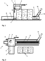
- FIGs 1 and 2 show a schematic illustration of a bale opener 1 according to the prior art for taking off fiber flocks 10 from fiber bales 2.
- Figure 1 shows the bale opener 1 in a frontal view, and Figure 2 , in a top view.
- the bale opener 1 is made up essentially of a take-off tower 3 and a take-off arm 6.
- the take-off arm 6 is fastened to one side of the take-off tower 3, and projects freely across the fiber bales 2.
- the take-off tower 3 is equipped with a chassis 4.
- the take-off tower 3 is moved along the fiber bales 2 on rails 5 by means of the chassis 4. As a result of this movement 12, the take-off arm 6 mounted on the take-off tower 3 is guided across the surface of the fiber bales 2.
- a take-off unit 7 is situated in the take-off arm 6.
- the take-off unit 7 removes fiber flocks 10 from the fiber bales 2.
- the fiber flocks 10 are brought by the take-off arm 6 and the take-off tower 3 to a conveying channel 8.
- the conveying channel 8, and thus also the transport path from the take-off unit 7 to the conveying channel 8, are under a certain negative pressure that is used to pneumatically convey the fiber flocks 10 from the take-off unit 7 through the conveying channel into a pneumatic fiber flock transport system 14.
- the conveying channel 8 is closed between the take-off tower 3 and the fiber flock transport system 14 by a channel cover 9.
- the channel cover 9 is rolled on and off, so that the conveying channel 8 in its active length, which continuously changes due to the travel motion 12 of the take-off tower 3, is closed by the channel cover 9.
- the fastening of the take-off arm 6 to the take-off tower 3 has a height-adjustable design, so that the fiber bales 2 may be continuously stripped.
- the movement 13 of the take-off arm 3 serves to ensure uniform take-off of the fiber flocks 10 from the surface of the fiber bales 2.
- the take-off tower 3 with its travel motion 12 has traveled across all fiber bales 2, the direction of the travel motion 12 of the take-off tower 3 may be reversed.
- fiber bales 2 are provided for take-off on both sides of the conveying channel 8, as the result of a rotary motion 11 the take-off tower may swivel the take-off arm 6 to the other side of the conveying channel 9.
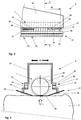
- FIG 3 shows a schematic illustration of a first embodiment of a take-off arm 6 according to the invention in a partial view
- Figure 4 shows a schematic sectional illustration at location X-X according to Figure 3
- the take-off arm 6 has a housing 15, and a take-off unit 7 situated within the housing 15.
- the take-off unit 7 is [designed] as a detaching roller 22 having an axial length 16 and with take-off teeth 23 situated on its surface over the axial length 16.
- the take-off teeth 23 may be designed as individual teeth, or in the form of toothed disks.
- a pressing element 17 made up of a mounting 18, a hold-down plate 19, and a grid 20 is situated below the housing 15.
- the length of the pressing element 17 exceeds the axial length 16 of the detaching roller 22 in order for the fiber bales 2 to properly travel across in their entire extent.
- a hold-down plate 19 is illustrated in each case, corresponding to the possible travel motions 12 on both sides of the grid 20.
- the hold-down plates 19 are connected to the grid 20, and together with the grid 20 are mounted on the mountings 18.
- the mountings 18 in turn are fastened to load cells 21, the load cells 21 being secured to the elastic devices 27, and the elastic devices 27 are fastened to the housing 15 of the take-off arm 6.
- the pressing element 17 is thus coupled to the housing 15 of the take-off arm 6 only via the load cells 21 and elastic devices 27 in turn, without further connection.
- Figure 4 also illustrates the fiber bale 2 to be stripped, to which the take-off arm 6 applies the contact force F via the pressing element 17. Due to the irregular height of the fiber bale 2, the contact force F is not necessarily uniformly distributed over the entire surface area of the pressing element 17. However, the nonuniform distribution of the contact force F is compensated for by the arrangement of four load cells 21. The greater the contact force F, the more strongly the upper portion of the fiber bale 2 to be stripped is compressed, and higher take-off performance is achieved by the engagement of the take-off teeth 23 of the detaching roller 22 with the fiber bale 2. The actual penetration depth of the take-off teeth 23 into the fiber bale 2 is determined by the grid 20 that rests on the surface of the fiber bale.
- each elastic device is designed as a leaf spring 28, one end of which is connected to the load cell 21 and another end is connected to the housing 15 via a shifting device 29 which is provided to adjust the penetration of the take-off teeth 23.
- the shifting device 29 can be designed as a scale which can set a range, for example 0-20mm, preferably 0-12mm, within this range, the pressing element 17 together with the load cells 21 can be adjusted up and down automatically when resting on the surface of the fiber bale 2, so the penetration of the take-off teeth 23 into the fiber bale 2 is adjusted, and so the unsightly bale surface can be avoided.
- Figure 4 also shows magnets 26 on the hold-down plates 19 for separation of metal particles.
- the metal particles situated on the surface of the fiber bale 2 are retained by the magnets, and thus do not enter the area of the take-off teeth 23.
- Figure 5 shows a schematic illustration of a second embodiment of a take-off arm according to the invention in a partial view
- Figure 6 shows a schematic sectional illustration at location Y-Y according to Figure 5
- the take-off arm 6 has a housing 15 and a take-off unit 7 situated within the housing 15.
- the take-off unit 7 is [designed] as a detaching roller 22 having an axial length 16, and with take-off teeth 23 situated on its surface.
- the take-off teeth 23 may be designed as individual teeth, or in the form of toothed disks.
- a pressing element 17 made up of a pressing roller 24 that is mounted in bearing shields 25, and a grid 20 is situated below the housing 15.
- the length of the pressing element 17 exceeds the axial length 16 of the detaching roller 22 in order for the fiber bales 2 to properly travel across in their entire extent.
- a pressing roller 24 is illustrated in each case, corresponding to the possible travel motions 12 on both sides of the grid 20.
- the grid 20 is likewise mounted on the bearing shields 25.
- the bearing shields 25 in turn are fastened to load cells 21, the load cells 21 are fastened to the elastic devices 27 and the elastic devices 27 being secured to the housing 15 of the take-off arm 6.
- the pressing element 17 is thus coupled to the housing 15 of the take-off arm 6 only via the load cells 21 and elastic devices 27 in turn, without further connection.
- Figure 6 also illustrates the fiber bale 2 to be stripped, to which the take-off arm 6 applies the contact force F via the pressing element 17 and the pressing rollers 24. Due to the irregular height of the fiber bale 2, the contact force F is not necessarily uniformly distributed over the two pressing rollers 24 or their axial length. However, the nonuniform distribution of the contact force F is compensated for by the arrangement of four load cells 21. The greater the contact force F, the more strongly the upper portion of the fiber bale 2 to be stripped is compressed by the pressing rollers 24, and higher take-off performance is achieved by the engagement of the take-off teeth 23 of the detaching roller 22 with the fiber bale 2.
- each elastic device 27 is designed as a leaf spring 28, one end of which is connected to the load cell 21 and another end is connected to the housing 15 via a shifting device 29 which is provided to adjust the penetration of the take-off teeth 23.
- the shifting device 29 can be designed as a scale which can set a range, for example 0-20mm, preferably 0-12mm, within this range, the pressing element 17 together with the load cells 21 can be adjusted up and down automatically when resting on the surface of the fiber bale 2, so the penetration of the take-off teeth 23 into the fiber bale 2 is adjusted, and so the unsightly bale surface can be avoided.
Landscapes
- Engineering & Computer Science (AREA)
- Textile Engineering (AREA)
- Preliminary Treatment Of Fibers (AREA)
Abstract
Description
- The invention relates to a take-off arm for a bale opener for taking off fiber flocks from fiber bales, having a housing, a detaching roller, and a pressing element, and to a bale opener and to a method for taking off fiber flocks from fiber bales, using a bale opener.
- Bale take-off machines or bale openers are used to extract fibers or fiber flocks from pressed fiber bales. For this purpose, a take-off unit is moved across the fiber bales. The take-off unit is fastened to a take-off arm, the height of which is set according to the fiber bales that are present. The take-off arm in turn is mounted on a take-off tower. The take-off tower allows the take-off unit to be moved across the surface of the fiber bales to be stripped. For this purpose, the take-off tower is situated on a chassis or a rotating frame. A chassis, which is usually guided on rails, may be used to move across a row of bales. If the fiber bales are arranged in a circle around the take-off tower, the take-off tower is mounted on a rotating frame. A combination of a chassis and a rotating frame is present when fibers or fiber flocks are extracted from a first row of fiber bales in one direction and from a second row of fiber bales in the opposite direction.
- The bale opener is located at the beginning of processing lines in a spinning preparation (blow room) for processing fiber material, for example cotton or synthetic fibers or mixtures thereof, and has a decisive influence on the continuity of the sequences within the spinning preparation. In the bale opener, the fiber material delivered in bales is extracted from the bales by taking off fiber flocks, and is transferred to a pneumatic transport system. The pneumatic transport system carries the fiber flocks through pipelines to the downstream cleaning machines.
- In bale openers that are common nowadays, the take-off arm is mounted on the take-off tower so as to be vertically adjustable. The vertical adjustment takes place by means of chain drives, belt drives, or spindle drives at which the take-off arm is raised or lowered.
- Various sensors are provided for determining the position of the take-off arm relative to the surface of the fiber bales. The take-off performance of the take-off unit contained in the take-off arm results from the position of the take-off arm relative to the surface of the fiber bales.
- Various designs for controllers for take-off arms, and thus for the take-off performance, are known from the prior art. For example,
EP 2 322 701 A1 -
EP 3 009 539 A1 - In addition, due to the the engagement depth of the take-off teeth into the fiber bale(i.e. take-off distance) in prior art is fixed during processing fiber material, some of the fiber material can not be taken off in case of hard bales, the roller, which is only engaged next to the grate bars, is not able to remove the fiber material which can not be covered and clamped by the take off teeth. As a result, some "ribs" are formed on the surface of bales from passage to passage, this creates an unsightly surface, and the contact pressure increases until, due to overload, a new scan must be made.
- The object of the invention is to provide a bale opener having a take-off arm that allows reliable, directly controllable vertical adjustment and positioning of the take-off arm, and allows a self-regulating take-off distance as well, free of influences from the design of the take-off arm. A further object of the invention is to provide a method for a reliably controllable take-off quantity of fiber flocks from fiber bales, using a bale opener.
- The object is achieved by the features in the characterizing portion of the independent claims.
- For achieving the object, a force-dependent vertical adjustment of the take-off arm for a bale opener for taking off fiber flocks from fiber bales is proposed. The take-off arm has a housing, at least one detaching roller having an axial length, and a pressing element. The pressing element is connected to load cells, and the load cells are connected to the housing via elastic devices. The fastening of the pressing element to the load cells, the housing, and thus to the take-off arm, is ensured only via the load cells and elastic devices in turn. The pressing element is mounted on the take-off arm in such a way that the pressing element contacts the fiber bales when the take-off arm is lowered onto the fiber bales. Upon further lowering of the take-off arm after initial contact of the pressing element with the surface of the fiber bales, the pressing element is pressed onto the fiber bales by the intrinsic weight of the take-off arm. As a result of the pressing element being connected to the housing of the take-off tower via load cells and elastic devices, the reduction of the intrinsic weight of the take-off arm due to the support by the fiber bales is registered via the load cells. The contact force with which the take-off arm acts on the fiber bales may be appropriately measured by the load cells and the take-off distance may be adjusted by the elastic devices automatically. It has been shown that use of four load cells to compensate for tilted positions is advantageous. Since the surfaces of the fiber bales do not form a uniform or parallel plane with respect to the pressing element, the actual bearing force exerted by the pressing element on the fiber bales is not equal at all locations on the pressing element. However, when multiple load cells are used, this situation is compensated for by the evaluation unit and a contact force may be determined which is independent of the position of the take-off arm or the pressing element. In addition, influencing of the lifting mechanism or of the guides of the take-off arm is excluded by directly measuring the contact force on the pressing element.
- Various designs of so-called force transducers may be used in load cells. For example, the use of force transducers is known, in which the force acts on an elastic spring body and deforms it. The deformation of the spring body is converted into the change in voltage, using strain gauges whose electrical resistance changes with the strain. The voltage and thus the change in strain are recorded via a measuring amplifier. This value may be converted into a measured force value, based on the elastic properties of the spring body. Bending beams, annular torsion springs, or other designs are used as spring bodies. In another design of load cells, piezoceramic elements are used. Microscopic dipoles form within the unit cells of the piezocrystal due to the directed deformation of a piezoelectric material. Summing over the associated electrical field in all unit cells of the crystal, results in a macroscopically measurable voltage that can be converted into a measured force value. Load cells are known from the prior art, and are currently widely used in force and weight measurement.
- The pressing element is advantageously designed as a grid having hold-down plates, and the take-off unit is designed as a detaching roller having take-off teeth. The grid is situated below the detaching roller, and the detaching roller engages with the take-off teeth through the grid. The grid mounted below the detaching roller represents the actual contact point with the surface of the fiber bales. The hold-down plates mounted on the grid in the travel direction of the take-off tower are used to guide the fiber flocks, which are standing up on the surface of the fiber bales, beneath the grid during a travel motion of the take-off tower, and thus, of the take-off arm. For this purpose, the hold-down plates are guided obliquely upwardly away from the grid. For a detaching roller that is usable on both sides, corresponding hold-down plates are mounted on both sides of the grid. The hold-down plates together with the grid form the pressing element. The take-off teeth of the detaching roller engage through the grid, and extract fiber flocks from the surface of the fiber bales due to the rotary motion of the detaching roller. As a result of the rotary motion of the detaching roller, the take-off teeth are moved by the fiber bales, and therefore do not assist in supporting the take-off arm on the fiber bales.
- The elastic device may have various designs, e.g. hydraulic dampers or deformable plastic blocks. Preferably the elastic device is designed as a leaf spring, one end of which is connected to the load cell and another end is connected to the housing via a shifting device which is provided to adjust the penetration of take-off teeth. Because of this design the take-off distance, i.e. the penetration of take-off teeth into the fiber bales through the grid is flexible and will be automatically adjusted by the elastic device, whereas the distance of the possible adjustment is limited by the stiffeness of elastic device or by the spring rate respectively.
- Advantageously a stop plate is arranged on the housing opposite the end of the leaf spring connected to the load cell, so as to stop the leaf spring and reach a maximum take-off distance. This design prevents overstretching of the leaf spring and thus damage to the elastic device.
- The grid advantageously has a length that corresponds at least to the axial length of the detaching roller on which the detaching roller is provided with take-off teeth. The grid thus also has the function of preventing the take-off teeth from tearing excessively large fiber flocks from the fiber bales. The length of the grid, and thus also of the hold-down plates, ensures that the pressing element formed by the grid and the hold-down plates comes to rest on the fiber bales over the entire axial length of the detaching roller. The result is uniform take-off on the surface of the fiber bales.
- In one alternative embodiment, the pressing element is designed as a guide plate. In one design of the take-off unit, having a grid that does not rest on the surface of the fiber bales, the guide plates represent the contact between the take-off arm and the fiber bales, and are appropriately connected to the take-off arm via load cells for measuring the contact force. In this case, the grid is used solely to prevent the take-off teeth from tearing excessively large fiber flocks from the fiber bales.
- In another alternative embodiment, the pressing element is designed as multiple guide rails that are situated beneath the grid and that slide over the fiber bales. The grid itself does not rest on the fiber bales. The guide rails in turn are mounted on the take-off arm via load cells and elastic devices in order. Necessary hold-down plates may be fastened to the guide rails to avoid incorrect measurement of the contact force due to the fiber flocks, on the surface of the fiber bales, that run in in the area of the detaching roller. The guide rails may also be designed as grids that cover a portion of the axial length of the detaching roller. In this case, the grid is provided between the guide rails and the detaching roller only at locations where no guide rails in the form of partial grids are situated.
- In another alternative embodiment, the pressing element is designed as at least one pressing roller having bearing shields, and the load cells are situated on the bearing shields of the pressing roller and elastic devices are situated on the load cells. Instead of the guide plates, pressing rollers are used to ensure the run-in of the surfaces of the fiber bales beneath the take-off unit. When the take-off arm moves across the fiber bales, the surface of the fiber bales is made uniform by the pressing roller before the take-off unit engages with the surface.
- Magnets for separating metallic impurities from the fiber bales are advantageously mounted on the pressing element. The magnets are to be provided on the hold-down plates, along the entire axial length of the take-off unit. The magnets may be mounted as a plurality of individual magnets or as a strip magnet that extends over the entire length. Strip magnets in the form of foils are often used in the prior art. As a result of the magnets, metallic impurities that could cause damage on the take-off unit or in a subsequent process stage may be retained even before the fiber flocks are extracted from the fiber bales. Cleaning of the magnets may be provided, for example, at the end of a row of fiber bales. The cleaning may be performed by hand or by an automated cleaning device. When strip magnets are used, it is also easily possible to replace the used strip with a new, cleaned strip. As an alternative to magnet strips, magnetic drums may be used. Magnetic drums may be mounted on both sides of the pressing element, or also on the take-off arm. The magnetic drums may have a self-cleaning system; for example, during rotation of the take-off arm, when the direction changes, the magnets are deactivated in a position remote from the fiber bales, and the drums are cleaned in this way.
- Also proposed is a bale opener having a take-off arm according to the above description.
- To achieve the further object, a method for taking off fiber flocks from fiber bales, using a bale opener, is proposed, the bale opener having a take-off arm with a housing, at least one detaching roller having take-off teeth, and a pressing element. A contact force of the take-off arm on the fiber bales is continuously measured by an evaluation of load cells situated between the pressing element and the housing, and a penetration of the take-off teeth is adjusted by elastic devices situated between the load cells and the housing.
- By using a load cell, it is possible to move the take-off tower across the surface of the fiber bales at a specified pressure. A contact force of the take-off arm on the fiber bales is determinable via the load cells. A penetration of the take-off teeth is adjusted through the elastic devices automatically. The take-off arm together with the pressing element fastened thereto is lowered onto the surface of the fiber bales until a certain load is determined via the load cells. The load corresponds to the contact force with which the pressing element, situated on the take-off arm, is pressed onto the surface of the fiber bales. The pressure with which the pressing element is pressed onto the fiber bales, the state and the working speed of the take-off unit, and the travel speed of the take-off tower with which the take-off arm is guided across the fiber bales essentially determine the take-off quantity. The take-off quantity of the bale opener may now be directly influenced by a direct measurement of the contact force and an associated control of the lifting mechanism of the take-off arm. Due to the fact that the fiber bales cannot be uniformly stripped by the take-off operation, height differences result between the individual fiber bales or also within fiber bales. If the level of a fiber bale surface now increases, the contact force also increases. This is registered by the load cells, and the control may respond by appropriately lifting the take-off arm, and the elastic devices can adjust the pressing element automatically within a designated scope so as to adjust the penetration of the take-off teeth into the fiber bales accordingly.
- Preferably the penetration is automatically adjusted in a range of 0 mm to12 mm. It has been shown that a further adjustment of the automatic adjustment requires an increased effort in the design of the elastic device, which offers no further significant advantages. An adjustment of the penetration of the take-off teeth up to 12 mm is sufficient for a perfect operation of the bale opener.
- By calibration, a zero value for the contact force is advantageously determined by measuring forces that act on the load cells due to the intrinsic weight of the pressing element. In a position of the take-off arm that is remote from the surface of the fiber bales, by fastening the pressing element to the housing of the take-off arm the load cells are placed under load by the intrinsic weight of the pressing element. If the take-off arm is now lowered onto the fiber bales, the load cells are initially relieved of load by the magnitude of the intrinsic weight of the pressing element. However, the relief of load results in a pressure on the surface of the fiber bales, which must be taken into account in determining the bearing pressure.
- The invention is explained in greater detail below based on exemplary embodiments and with reference to the drawings, which show the following:
- Figure 1
- shows a schematic illustration of a bale opener in a frontal view;
- Figure 2
- shows a schematic illustration of a bale opener in a top view;
- Figure 3
- shows a schematic illustration of a first embodiment of a take-off arm according to the invention in a partial view;
- Figure 4
- shows a schematic sectional illustration at location X-X according to
Figure 3 ; - Figure 5
- shows a schematic illustration of a second embodiment of a take-off arm according to the invention in a partial view and
- Figure 6
- shows a schematic sectional illustration at location Y-Y according to
Figure 5 . -
Figures 1 and 2 show a schematic illustration of abale opener 1 according to the prior art for taking offfiber flocks 10 fromfiber bales 2.Figure 1 shows thebale opener 1 in a frontal view, andFigure 2 , in a top view. Thebale opener 1 is made up essentially of a take-off tower 3 and a take-offarm 6. The take-offarm 6 is fastened to one side of the take-off tower 3, and projects freely across thefiber bales 2. The take-off tower 3 is equipped with achassis 4. The take-off tower 3 is moved along thefiber bales 2 onrails 5 by means of thechassis 4. As a result of thismovement 12, the take-offarm 6 mounted on the take-off tower 3 is guided across the surface of thefiber bales 2. A take-offunit 7 is situated in the take-offarm 6. The take-offunit 7 removesfiber flocks 10 from thefiber bales 2. Thefiber flocks 10 are brought by the take-offarm 6 and the take-off tower 3 to a conveyingchannel 8. The conveyingchannel 8, and thus also the transport path from the take-offunit 7 to the conveyingchannel 8, are under a certain negative pressure that is used to pneumatically convey thefiber flocks 10 from the take-offunit 7 through the conveying channel into a pneumatic fiberflock transport system 14. The conveyingchannel 8 is closed between the take-off tower 3 and the fiberflock transport system 14 by achannel cover 9. During atravel motion 12 of the take-off tower 3, thechannel cover 9 is rolled on and off, so that the conveyingchannel 8 in its active length, which continuously changes due to thetravel motion 12 of the take-off tower 3, is closed by thechannel cover 9. - The fastening of the take-off
arm 6 to the take-off tower 3 has a height-adjustable design, so that thefiber bales 2 may be continuously stripped. Themovement 13 of the take-offarm 3 serves to ensure uniform take-off of thefiber flocks 10 from the surface of thefiber bales 2. When the take-off tower 3 with itstravel motion 12 has traveled across allfiber bales 2, the direction of thetravel motion 12 of the take-off tower 3 may be reversed. Whenfiber bales 2 are provided for take-off on both sides of the conveyingchannel 8, as the result of a rotary motion 11 the take-off tower may swivel the take-offarm 6 to the other side of the conveyingchannel 9. -
Figure 3 shows a schematic illustration of a first embodiment of a take-offarm 6 according to the invention in a partial view, andFigure 4 shows a schematic sectional illustration at location X-X according toFigure 3 . The take-offarm 6 has ahousing 15, and a take-offunit 7 situated within thehousing 15. The take-offunit 7 is [designed] as a detachingroller 22 having anaxial length 16 and with take-offteeth 23 situated on its surface over theaxial length 16. The take-offteeth 23 may be designed as individual teeth, or in the form of toothed disks. Apressing element 17 made up of a mounting 18, a hold-down plate 19, and agrid 20 is situated below thehousing 15. The length of thepressing element 17 exceeds theaxial length 16 of the detachingroller 22 in order for thefiber bales 2 to properly travel across in their entire extent. Based on the illustrated design of thebale opener 1 inFigures 1 and 2 , a hold-down plate 19 is illustrated in each case, corresponding to thepossible travel motions 12 on both sides of thegrid 20. The hold-downplates 19 are connected to thegrid 20, and together with thegrid 20 are mounted on themountings 18. Themountings 18 in turn are fastened to loadcells 21, theload cells 21 being secured to theelastic devices 27, and theelastic devices 27 are fastened to thehousing 15 of the take-offarm 6. Thepressing element 17 is thus coupled to thehousing 15 of the take-offarm 6 only via theload cells 21 andelastic devices 27 in turn, without further connection.Figure 4 also illustrates thefiber bale 2 to be stripped, to which the take-offarm 6 applies the contact force F via thepressing element 17. Due to the irregular height of thefiber bale 2, the contact force F is not necessarily uniformly distributed over the entire surface area of thepressing element 17. However, the nonuniform distribution of the contact force F is compensated for by the arrangement of fourload cells 21. The greater the contact force F, the more strongly the upper portion of thefiber bale 2 to be stripped is compressed, and higher take-off performance is achieved by the engagement of the take-offteeth 23 of the detachingroller 22 with thefiber bale 2. The actual penetration depth of the take-offteeth 23 into thefiber bale 2 is determined by thegrid 20 that rests on the surface of the fiber bale. It is necessary to adjust the distance between thegrid 20 and the detachingroller 22, i.e. take-off distance, in order to adjust the engagement depth of the take-offteeth 23 into thefiber bale 2. It is achieved by theelastic devices 27, each elastic device is designed as aleaf spring 28, one end of which is connected to theload cell 21 and another end is connected to thehousing 15 via a shiftingdevice 29 which is provided to adjust the penetration of the take-off teeth 23. The shiftingdevice 29 can be designed as a scale which can set a range, for example 0-20mm, preferably 0-12mm, within this range, thepressing element 17 together with theload cells 21 can be adjusted up and down automatically when resting on the surface of thefiber bale 2, so the penetration of the take-offteeth 23 into thefiber bale 2 is adjusted, and so the unsightly bale surface can be avoided. -
Figure 4 also showsmagnets 26 on the hold-downplates 19 for separation of metal particles. The metal particles situated on the surface of thefiber bale 2 are retained by the magnets, and thus do not enter the area of the take-off teeth 23. -
Figure 5 shows a schematic illustration of a second embodiment of a take-off arm according to the invention in a partial view, andFigure 6 shows a schematic sectional illustration at location Y-Y according toFigure 5 . The take-offarm 6 has ahousing 15 and a take-offunit 7 situated within thehousing 15. The take-offunit 7 is [designed] as a detachingroller 22 having anaxial length 16, and with take-offteeth 23 situated on its surface. The take-offteeth 23 may be designed as individual teeth, or in the form of toothed disks. Apressing element 17 made up of apressing roller 24 that is mounted in bearingshields 25, and agrid 20 is situated below thehousing 15. The length of thepressing element 17 exceeds theaxial length 16 of the detachingroller 22 in order for thefiber bales 2 to properly travel across in their entire extent. Based on the illustrated design of thebale opener 1 inFigures 1 and 2 , apressing roller 24 is illustrated in each case, corresponding to thepossible travel motions 12 on both sides of thegrid 20. Thegrid 20 is likewise mounted on the bearing shields 25. The bearing shields 25 in turn are fastened to loadcells 21, theload cells 21 are fastened to theelastic devices 27 and theelastic devices 27 being secured to thehousing 15 of the take-offarm 6. Thepressing element 17 is thus coupled to thehousing 15 of the take-offarm 6 only via theload cells 21 andelastic devices 27 in turn, without further connection.Figure 6 also illustrates thefiber bale 2 to be stripped, to which the take-offarm 6 applies the contact force F via thepressing element 17 and thepressing rollers 24. Due to the irregular height of thefiber bale 2, the contact force F is not necessarily uniformly distributed over the twopressing rollers 24 or their axial length. However, the nonuniform distribution of the contact force F is compensated for by the arrangement of fourload cells 21. The greater the contact force F, the more strongly the upper portion of thefiber bale 2 to be stripped is compressed by thepressing rollers 24, and higher take-off performance is achieved by the engagement of the take-offteeth 23 of the detachingroller 22 with thefiber bale 2. The actual penetration depth of the take-offteeth 23 into thefiber bale 2 is determined by thegrid 20 that rests on the surface of thefiber bale 2. It is necessary to adjust the distance between thegrid 20 and the detachingroller 22, i.e. take-off distance, in order to adjust the engagement depth of the take-offteeth 23 into thefiber bale 2. It is achieved by theelastic devices 27, eachelastic device 27 is designed as aleaf spring 28, one end of which is connected to theload cell 21 and another end is connected to thehousing 15 via a shiftingdevice 29 which is provided to adjust the penetration of the take-off teeth 23. The shiftingdevice 29 can be designed as a scale which can set a range, for example 0-20mm, preferably 0-12mm, within this range, thepressing element 17 together with theload cells 21 can be adjusted up and down automatically when resting on the surface of thefiber bale 2, so the penetration of the take-offteeth 23 into thefiber bale 2 is adjusted, and so the unsightly bale surface can be avoided. -
- 1
- bale opener
- 2
- fiber bales
- 3
- take-off tower
- 4
- chassis
- 5
- rails
- 6
- take-off arm
- 7
- take-off unit
- 8
- conveying channel
- 9
- channel cover
- 10
- fiber flocks
- 11
- rotary motion of the take-off tower
- 12
- travel motion of the take-off tower
- 13
- movement of the take-off arm
- 14
- fiber flock transport system
- 15
- housing
- 16
- axial length of the take-off unit
- 17
- pressing element
- 18
- mounting
- 19
- hold-down plate
- 20
- grid
- 21
- load cell
- 22
- detaching roller
- 23
- take-off teeth
- 24
- pressing roller
- 25
- bearing shield
- 26
- magnet
- 27
- elastic device
- 28
- leaf spring
- 29
- shifting device
- 30
- stop plate
- F
- contact force
Claims (13)
- A take-off arm (6) for a bale opener (1) for taking off fiber flocks (10) from fiber bales (2), having a housing (15), at least one take-off unit (7) having an axial length (16), and a pressing element (17), characterized in that the pressing element (17) is connected to load cells (21), and the load cells (21) are connected to the housing (15) via elastic devices (27).
- The take-off arm (6) according to Claim 1, characterized in that the elastic device (27) is designed as a leaf spring (28), one end of which is connected to the load cell (21) and another end is connected to the housing (15) via a shifting device (29) which is provided to adjust the penetration of the take-off teeth (23).
- The take-off arm (6) according to Claim 2, characterized in that a stop plate (30) is arranged on the housing (15) opposite the end of the leaf spring (28) connected to the load cell (21).
- The take-off arm (6) according to one of the preceding claims, characterized in that the pressing element (17) is designed as a grid (20) having hold-down plates (19), and the take off unit (7) is designed as a detaching roller (22) having take-off teeth (23), wherein the grid (20) is situated below the detaching roller (22), and the detaching roller (22) engages with the take-off teeth (23) through the grid (20).
- The take-off arm (6) according to Claim 4, characterized in that the grid (20) has a length that corresponds at least to the axial length (16) of the detaching roller (22) on which the detaching roller (22) is provided with take-off teeth (23).
- The take-off arm (6) according to Claim 5, characterized in that the hold-down plates (19) are provided on both sides of the grid (20) over the entire length of the grid (20).
- The take-off arm (6) according to one of the preceding claims, characterized in that the pressing element (17) is designed as a guide plate.
- The take-off arm (6) according to one of the preceding claims, characterized in that pressing element (17) is designed as at least one pressing roller (24) having bearing shields (25), and the load cells (21) are situated on the bearing shields (25) of the pressing roller (24).
- The take-off arm (6) according to one of the preceding claims, characterized in that magnets (26) for separating metallic impurities from the fiber bales (2) are mounted on the pressing element (17).
- A bale opener (1) having a take-off arm (6) according to one of the preceding claims.
- A method for taking off fiber flocks (10) from fiber bales (2) using a bale opener (1), wherein the bale opener (1) has a take-off arm (6) with a housing (15), at least one take-off unit (7), and a pressing element (17), whereby the take-off unit (7) is designed as a detaching roller (22) having take-off teeth (23), characterized in that a contact force (F) of the take-off arm (6) on the fiber bales (2) is continuously measured by an evaluation of load cells (21) situated between the pressing element (17) and the housing (15), and a penetration of the take-off teeth (23) is adjusted by elastic devices (27) situated between the load cells (21) and the housing (15).
- The method according to Claim 11, characterized in that the penetration is automatically adjusted in a range of 0 mm to12 mm.
- The method according to Claim 11 or 12, characterized in that by calibration, a zero value for the contact force (F) is determined by measuring forces that act on the load cells (21) due to the intrinsic weight of the pressing element (17).
Applications Claiming Priority (1)
| Application Number | Priority Date | Filing Date | Title |
|---|---|---|---|
| CH11072019 | 2019-09-03 |
Publications (2)
| Publication Number | Publication Date |
|---|---|
| EP3789524A1 true EP3789524A1 (en) | 2021-03-10 |
| EP3789524B1 EP3789524B1 (en) | 2024-12-25 |
Family
ID=72243025
Family Applications (1)
| Application Number | Title | Priority Date | Filing Date |
|---|---|---|---|
| EP20192883.5A Active EP3789524B1 (en) | 2019-09-03 | 2020-08-26 | Bale opener |
Country Status (2)
| Country | Link |
|---|---|
| EP (1) | EP3789524B1 (en) |
| CN (1) | CN112442762B (en) |
Citations (5)
| Publication number | Priority date | Publication date | Assignee | Title |
|---|---|---|---|---|
| JPS6375122A (en) * | 1986-09-19 | 1988-04-05 | Ohara Tekkosho:Kk | Opening method in mixing and blowing process |
| DE3932281A1 (en) * | 1989-09-27 | 1991-04-04 | Hollingsworth Gmbh | Bale breaker for extracting fibre from compressed bales - comprising pressure rollers having sensors which generate upwards signal for extn. unit |
| EP2322701A1 (en) | 2009-11-16 | 2011-05-18 | Marzoli S.P.A. | Device and method for the automatic pick-up of fibre from a bale of fibre on a spinning line |
| EP3009539A1 (en) | 2014-10-16 | 2016-04-20 | Maschinenfabrik Rieter Ag | Bale opener |
| CN106637540A (en) * | 2017-02-22 | 2017-05-10 | 湖州东凯纺织有限公司 | Adjustable cotton grabbing trolley |
Family Cites Families (12)
| Publication number | Priority date | Publication date | Assignee | Title |
|---|---|---|---|---|
| DE2435290C2 (en) * | 1974-07-23 | 1986-02-20 | Schubert & Salzer Maschinenfabrik Ag, 8070 Ingolstadt | Method and device for opening fiber bales |
| SU1044687A1 (en) * | 1981-06-01 | 1983-09-30 | Ивановский Ордена "Знак Почета" Энергетический Институт Им.В.И.Ленина | Apparatus for stabilizing the output of bale breaking-up machine |
| DE3636751C2 (en) * | 1986-10-29 | 1996-02-01 | Hergeth Hubert A | Procedure for determining the limits of a bale display for bale openers |
| DE3928835C2 (en) * | 1989-08-31 | 2001-06-21 | Truetzschler Gmbh & Co Kg | Opening device for opening pressed fiber bales, e.g. B. cotton and rayon bales u. the like |
| DE3933271A1 (en) * | 1989-10-05 | 1991-04-18 | Hollingsworth Gmbh | DEVICE FOR OPENING PRESSED FIBER BALLS |
| JP3299508B2 (en) * | 1998-07-10 | 2002-07-08 | 日本スピンドル製造株式会社 | Spreading speed control device for open bale opener |
| WO2009062325A1 (en) * | 2007-11-15 | 2009-05-22 | Maschinenfabrik Rieter Ag | Bale opening machine |
| CH706899A1 (en) * | 2012-08-29 | 2014-03-14 | Rieter Ag Maschf | Off member for removing fiber flocks from fiber bales. |
| CN104328534A (en) * | 2014-10-13 | 2015-02-04 | 昆山奥朋纺织机械有限公司 | Small bale plucker |
| CH712367A1 (en) * | 2016-04-15 | 2017-10-31 | Rieter Ag Maschf | Method for calibrating the support force of a removal organ of a bale opener and bale opener. |
| CN108588905A (en) * | 2018-03-27 | 2018-09-28 | 宿迁超博纺织有限公司 | A kind of elastic cleaning roller of griping cotton machine |
| CN209052822U (en) * | 2018-10-18 | 2019-07-02 | 浙江盛安纺织有限公司 | A kind of griping cotton machine absorption plant |
-
2020
- 2020-08-26 EP EP20192883.5A patent/EP3789524B1/en active Active
- 2020-09-02 CN CN202010910652.4A patent/CN112442762B/en active Active
Patent Citations (6)
| Publication number | Priority date | Publication date | Assignee | Title |
|---|---|---|---|---|
| JPS6375122A (en) * | 1986-09-19 | 1988-04-05 | Ohara Tekkosho:Kk | Opening method in mixing and blowing process |
| DE3932281A1 (en) * | 1989-09-27 | 1991-04-04 | Hollingsworth Gmbh | Bale breaker for extracting fibre from compressed bales - comprising pressure rollers having sensors which generate upwards signal for extn. unit |
| EP2322701A1 (en) | 2009-11-16 | 2011-05-18 | Marzoli S.P.A. | Device and method for the automatic pick-up of fibre from a bale of fibre on a spinning line |
| EP3009539A1 (en) | 2014-10-16 | 2016-04-20 | Maschinenfabrik Rieter Ag | Bale opener |
| US20160108558A1 (en) * | 2014-10-16 | 2016-04-21 | Maschinenfabrik Rieter Ag | Bale Opener |
| CN106637540A (en) * | 2017-02-22 | 2017-05-10 | 湖州东凯纺织有限公司 | Adjustable cotton grabbing trolley |
Also Published As
| Publication number | Publication date |
|---|---|
| EP3789524B1 (en) | 2024-12-25 |
| CN112442762B (en) | 2024-03-01 |
| CN112442762A (en) | 2021-03-05 |
Similar Documents
| Publication | Publication Date | Title |
|---|---|---|
| US11286584B2 (en) | Bale opener | |
| US9745672B2 (en) | Bale opener | |
| US8668429B2 (en) | Depalleting unloading conveyor | |
| CN103979256A (en) | Conduction band balance adjusting device and method thereof | |
| CN109559921A (en) | A kind of temperature detect switch (TDS) assembles riveting machine automatically | |
| EP3789524B1 (en) | Bale opener | |
| DE102013001110A1 (en) | Robot with a handling unit | |
| DE19620937B4 (en) | sheet feeder | |
| US4912957A (en) | Smart straightening press | |
| JP3299508B2 (en) | Spreading speed control device for open bale opener | |
| CN113371516B (en) | Full-automatic stacking device and die cutting machine | |
| KR102021196B1 (en) | Sensing device for reclaimer | |
| CN119793930A (en) | A device for testing the compression strength of automobile shock-absorbing springs | |
| US10323340B2 (en) | Process for calibrating the loading force of a breaker element of a bale opener and the bale opener | |
| EP0552743A1 (en) | Automatic slide-on panel loading system | |
| CN109941802B (en) | Elastic cloth vibration feeding mechanism and method | |
| EP1717174B1 (en) | Feeder with safety device | |
| CN201845748U (en) | Feeding and discharging device | |
| CN220202116U (en) | Carding machine | |
| CN219597393U (en) | Laser cutting part sorting device and laser cutting device | |
| CN219545931U (en) | Anti-pinch mechanism and anti-pinch conveyor | |
| KR102117778B1 (en) | Sheet element processing machine and detection system for detecting double sheets in the sheet element processing machine | |
| CN112042431A (en) | Melon scion seeding equipment | |
| JP5422324B2 (en) | Care nut or discharge screw support nut wear detection method and apparatus provided in solid culture apparatus | |
| CN213505148U (en) | Prevent work or material rest on off tracking carpet covers |
Legal Events
| Date | Code | Title | Description |
|---|---|---|---|
| PUAI | Public reference made under article 153(3) epc to a published international application that has entered the european phase |
Free format text: ORIGINAL CODE: 0009012 |
|
| STAA | Information on the status of an ep patent application or granted ep patent |
Free format text: STATUS: THE APPLICATION HAS BEEN PUBLISHED |
|
| AK | Designated contracting states |
Kind code of ref document: A1 Designated state(s): AL AT BE BG CH CY CZ DE DK EE ES FI FR GB GR HR HU IE IS IT LI LT LU LV MC MK MT NL NO PL PT RO RS SE SI SK SM TR |
|
| AX | Request for extension of the european patent |
Extension state: BA ME |
|
| STAA | Information on the status of an ep patent application or granted ep patent |
Free format text: STATUS: REQUEST FOR EXAMINATION WAS MADE |
|
| 17P | Request for examination filed |
Effective date: 20210826 |
|
| RBV | Designated contracting states (corrected) |
Designated state(s): AL AT BE BG CH CY CZ DE DK EE ES FI FR GB GR HR HU IE IS IT LI LT LU LV MC MK MT NL NO PL PT RO RS SE SI SK SM TR |
|
| STAA | Information on the status of an ep patent application or granted ep patent |
Free format text: STATUS: EXAMINATION IS IN PROGRESS |
|
| 17Q | First examination report despatched |
Effective date: 20221109 |
|
| P01 | Opt-out of the competence of the unified patent court (upc) registered |
Effective date: 20230519 |
|
| GRAP | Despatch of communication of intention to grant a patent |
Free format text: ORIGINAL CODE: EPIDOSNIGR1 |
|
| STAA | Information on the status of an ep patent application or granted ep patent |
Free format text: STATUS: GRANT OF PATENT IS INTENDED |
|
| RAP3 | Party data changed (applicant data changed or rights of an application transferred) |
Owner name: RIETER AG |
|
| INTG | Intention to grant announced |
Effective date: 20240806 |
|
| GRAS | Grant fee paid |
Free format text: ORIGINAL CODE: EPIDOSNIGR3 |
|
| GRAA | (expected) grant |
Free format text: ORIGINAL CODE: 0009210 |
|
| STAA | Information on the status of an ep patent application or granted ep patent |
Free format text: STATUS: THE PATENT HAS BEEN GRANTED |
|
| AK | Designated contracting states |
Kind code of ref document: B1 Designated state(s): AL AT BE BG CH CY CZ DE DK EE ES FI FR GB GR HR HU IE IS IT LI LT LU LV MC MK MT NL NO PL PT RO RS SE SI SK SM TR |
|
| REG | Reference to a national code |
Ref country code: GB Ref legal event code: FG4D |
|
| REG | Reference to a national code |
Ref country code: CH Ref legal event code: EP |
|
| REG | Reference to a national code |
Ref country code: DE Ref legal event code: R096 Ref document number: 602020043597 Country of ref document: DE |
|
| REG | Reference to a national code |
Ref country code: IE Ref legal event code: FG4D |
|
| REG | Reference to a national code |
Ref country code: LT Ref legal event code: MG9D |
|
| PG25 | Lapsed in a contracting state [announced via postgrant information from national office to epo] |
Ref country code: HR Free format text: LAPSE BECAUSE OF FAILURE TO SUBMIT A TRANSLATION OF THE DESCRIPTION OR TO PAY THE FEE WITHIN THE PRESCRIBED TIME-LIMIT Effective date: 20241225 |
|
| PG25 | Lapsed in a contracting state [announced via postgrant information from national office to epo] |
Ref country code: FI Free format text: LAPSE BECAUSE OF FAILURE TO SUBMIT A TRANSLATION OF THE DESCRIPTION OR TO PAY THE FEE WITHIN THE PRESCRIBED TIME-LIMIT Effective date: 20241225 |
|
| PG25 | Lapsed in a contracting state [announced via postgrant information from national office to epo] |
Ref country code: BG Free format text: LAPSE BECAUSE OF FAILURE TO SUBMIT A TRANSLATION OF THE DESCRIPTION OR TO PAY THE FEE WITHIN THE PRESCRIBED TIME-LIMIT Effective date: 20241225 |
|
| PG25 | Lapsed in a contracting state [announced via postgrant information from national office to epo] |
Ref country code: NO Free format text: LAPSE BECAUSE OF FAILURE TO SUBMIT A TRANSLATION OF THE DESCRIPTION OR TO PAY THE FEE WITHIN THE PRESCRIBED TIME-LIMIT Effective date: 20250325 |
|
| PG25 | Lapsed in a contracting state [announced via postgrant information from national office to epo] |
Ref country code: LV Free format text: LAPSE BECAUSE OF FAILURE TO SUBMIT A TRANSLATION OF THE DESCRIPTION OR TO PAY THE FEE WITHIN THE PRESCRIBED TIME-LIMIT Effective date: 20241225 Ref country code: GR Free format text: LAPSE BECAUSE OF FAILURE TO SUBMIT A TRANSLATION OF THE DESCRIPTION OR TO PAY THE FEE WITHIN THE PRESCRIBED TIME-LIMIT Effective date: 20250326 |
|
| PG25 | Lapsed in a contracting state [announced via postgrant information from national office to epo] |
Ref country code: RS Free format text: LAPSE BECAUSE OF FAILURE TO SUBMIT A TRANSLATION OF THE DESCRIPTION OR TO PAY THE FEE WITHIN THE PRESCRIBED TIME-LIMIT Effective date: 20250325 |
|
| REG | Reference to a national code |
Ref country code: NL Ref legal event code: MP Effective date: 20241225 |
|
| PG25 | Lapsed in a contracting state [announced via postgrant information from national office to epo] |
Ref country code: NL Free format text: LAPSE BECAUSE OF FAILURE TO SUBMIT A TRANSLATION OF THE DESCRIPTION OR TO PAY THE FEE WITHIN THE PRESCRIBED TIME-LIMIT Effective date: 20241225 |
|
| REG | Reference to a national code |
Ref country code: AT Ref legal event code: MK05 Ref document number: 1754216 Country of ref document: AT Kind code of ref document: T Effective date: 20241225 |
|
| PG25 | Lapsed in a contracting state [announced via postgrant information from national office to epo] |
Ref country code: SM Free format text: LAPSE BECAUSE OF FAILURE TO SUBMIT A TRANSLATION OF THE DESCRIPTION OR TO PAY THE FEE WITHIN THE PRESCRIBED TIME-LIMIT Effective date: 20241225 |
|
| PG25 | Lapsed in a contracting state [announced via postgrant information from national office to epo] |
Ref country code: PL Free format text: LAPSE BECAUSE OF FAILURE TO SUBMIT A TRANSLATION OF THE DESCRIPTION OR TO PAY THE FEE WITHIN THE PRESCRIBED TIME-LIMIT Effective date: 20241225 |
|
| PG25 | Lapsed in a contracting state [announced via postgrant information from national office to epo] |
Ref country code: ES Free format text: LAPSE BECAUSE OF FAILURE TO SUBMIT A TRANSLATION OF THE DESCRIPTION OR TO PAY THE FEE WITHIN THE PRESCRIBED TIME-LIMIT Effective date: 20241225 |
|
| PG25 | Lapsed in a contracting state [announced via postgrant information from national office to epo] |
Ref country code: IS Free format text: LAPSE BECAUSE OF FAILURE TO SUBMIT A TRANSLATION OF THE DESCRIPTION OR TO PAY THE FEE WITHIN THE PRESCRIBED TIME-LIMIT Effective date: 20250425 |
|
| PG25 | Lapsed in a contracting state [announced via postgrant information from national office to epo] |
Ref country code: PT Free format text: LAPSE BECAUSE OF FAILURE TO SUBMIT A TRANSLATION OF THE DESCRIPTION OR TO PAY THE FEE WITHIN THE PRESCRIBED TIME-LIMIT Effective date: 20250428 |
|
| PG25 | Lapsed in a contracting state [announced via postgrant information from national office to epo] |
Ref country code: EE Free format text: LAPSE BECAUSE OF FAILURE TO SUBMIT A TRANSLATION OF THE DESCRIPTION OR TO PAY THE FEE WITHIN THE PRESCRIBED TIME-LIMIT Effective date: 20241225 |
|
| PG25 | Lapsed in a contracting state [announced via postgrant information from national office to epo] |
Ref country code: RO Free format text: LAPSE BECAUSE OF FAILURE TO SUBMIT A TRANSLATION OF THE DESCRIPTION OR TO PAY THE FEE WITHIN THE PRESCRIBED TIME-LIMIT Effective date: 20241225 Ref country code: AT Free format text: LAPSE BECAUSE OF FAILURE TO SUBMIT A TRANSLATION OF THE DESCRIPTION OR TO PAY THE FEE WITHIN THE PRESCRIBED TIME-LIMIT Effective date: 20241225 |
|
| PG25 | Lapsed in a contracting state [announced via postgrant information from national office to epo] |
Ref country code: SK Free format text: LAPSE BECAUSE OF FAILURE TO SUBMIT A TRANSLATION OF THE DESCRIPTION OR TO PAY THE FEE WITHIN THE PRESCRIBED TIME-LIMIT Effective date: 20241225 |
|
| PG25 | Lapsed in a contracting state [announced via postgrant information from national office to epo] |
Ref country code: SE Free format text: LAPSE BECAUSE OF FAILURE TO SUBMIT A TRANSLATION OF THE DESCRIPTION OR TO PAY THE FEE WITHIN THE PRESCRIBED TIME-LIMIT Effective date: 20241225 |
|
| REG | Reference to a national code |
Ref country code: DE Ref legal event code: R097 Ref document number: 602020043597 Country of ref document: DE |
|
| PG25 | Lapsed in a contracting state [announced via postgrant information from national office to epo] |
Ref country code: DK Free format text: LAPSE BECAUSE OF FAILURE TO SUBMIT A TRANSLATION OF THE DESCRIPTION OR TO PAY THE FEE WITHIN THE PRESCRIBED TIME-LIMIT Effective date: 20241225 |
|
| PGFP | Annual fee paid to national office [announced via postgrant information from national office to epo] |
Ref country code: DE Payment date: 20250819 Year of fee payment: 6 |
|
| PGFP | Annual fee paid to national office [announced via postgrant information from national office to epo] |
Ref country code: TR Payment date: 20250819 Year of fee payment: 6 Ref country code: IT Payment date: 20250829 Year of fee payment: 6 |
|
| PGFP | Annual fee paid to national office [announced via postgrant information from national office to epo] |
Ref country code: CH Payment date: 20250901 Year of fee payment: 6 |
|
| PGFP | Annual fee paid to national office [announced via postgrant information from national office to epo] |
Ref country code: CZ Payment date: 20250813 Year of fee payment: 6 |
|
| PLBE | No opposition filed within time limit |
Free format text: ORIGINAL CODE: 0009261 |
|
| STAA | Information on the status of an ep patent application or granted ep patent |
Free format text: STATUS: NO OPPOSITION FILED WITHIN TIME LIMIT |
|
| 26N | No opposition filed |
Effective date: 20250926 |
|
| PG25 | Lapsed in a contracting state [announced via postgrant information from national office to epo] |
Ref country code: MC Free format text: LAPSE BECAUSE OF FAILURE TO SUBMIT A TRANSLATION OF THE DESCRIPTION OR TO PAY THE FEE WITHIN THE PRESCRIBED TIME-LIMIT Effective date: 20241225 |
|
| PG25 | Lapsed in a contracting state [announced via postgrant information from national office to epo] |
Ref country code: LU Free format text: LAPSE BECAUSE OF NON-PAYMENT OF DUE FEES Effective date: 20250826 |
|
| GBPC | Gb: european patent ceased through non-payment of renewal fee |
Effective date: 20250826 |