EP3789518A1 - Procede de reparation localisee d'une barriere thermique endommagee - Google Patents
Procede de reparation localisee d'une barriere thermique endommagee Download PDFInfo
- Publication number
- EP3789518A1 EP3789518A1 EP20203886.5A EP20203886A EP3789518A1 EP 3789518 A1 EP3789518 A1 EP 3789518A1 EP 20203886 A EP20203886 A EP 20203886A EP 3789518 A1 EP3789518 A1 EP 3789518A1
- Authority
- EP
- European Patent Office
- Prior art keywords
- damaged
- thermal barrier
- particles
- equal
- ceramic coating
- Prior art date
- Legal status (The legal status is an assumption and is not a legal conclusion. Google has not performed a legal analysis and makes no representation as to the accuracy of the status listed.)
- Granted
Links
Images


Classifications
-
- F—MECHANICAL ENGINEERING; LIGHTING; HEATING; WEAPONS; BLASTING
- F01—MACHINES OR ENGINES IN GENERAL; ENGINE PLANTS IN GENERAL; STEAM ENGINES
- F01D—NON-POSITIVE DISPLACEMENT MACHINES OR ENGINES, e.g. STEAM TURBINES
- F01D5/00—Blades; Blade-carrying members; Heating, heat-insulating, cooling or antivibration means on the blades or the members
- F01D5/005—Repairing methods or devices
-
- C—CHEMISTRY; METALLURGY
- C25—ELECTROLYTIC OR ELECTROPHORETIC PROCESSES; APPARATUS THEREFOR
- C25D—PROCESSES FOR THE ELECTROLYTIC OR ELECTROPHORETIC PRODUCTION OF COATINGS; ELECTROFORMING; APPARATUS THEREFOR
- C25D13/00—Electrophoretic coating characterised by the process
- C25D13/02—Electrophoretic coating characterised by the process with inorganic material
-
- C—CHEMISTRY; METALLURGY
- C25—ELECTROLYTIC OR ELECTROPHORETIC PROCESSES; APPARATUS THEREFOR
- C25D—PROCESSES FOR THE ELECTROLYTIC OR ELECTROPHORETIC PRODUCTION OF COATINGS; ELECTROFORMING; APPARATUS THEREFOR
- C25D13/00—Electrophoretic coating characterised by the process
- C25D13/12—Electrophoretic coating characterised by the process characterised by the article coated
-
- C—CHEMISTRY; METALLURGY
- C25—ELECTROLYTIC OR ELECTROPHORETIC PROCESSES; APPARATUS THEREFOR
- C25D—PROCESSES FOR THE ELECTROLYTIC OR ELECTROPHORETIC PRODUCTION OF COATINGS; ELECTROFORMING; APPARATUS THEREFOR
- C25D13/00—Electrophoretic coating characterised by the process
- C25D13/18—Electrophoretic coating characterised by the process using modulated, pulsed, or reversing current
-
- C—CHEMISTRY; METALLURGY
- C25—ELECTROLYTIC OR ELECTROPHORETIC PROCESSES; APPARATUS THEREFOR
- C25D—PROCESSES FOR THE ELECTROLYTIC OR ELECTROPHORETIC PRODUCTION OF COATINGS; ELECTROFORMING; APPARATUS THEREFOR
- C25D13/00—Electrophoretic coating characterised by the process
- C25D13/20—Pretreatment
-
- C—CHEMISTRY; METALLURGY
- C25—ELECTROLYTIC OR ELECTROPHORETIC PROCESSES; APPARATUS THEREFOR
- C25D—PROCESSES FOR THE ELECTROLYTIC OR ELECTROPHORETIC PRODUCTION OF COATINGS; ELECTROFORMING; APPARATUS THEREFOR
- C25D13/00—Electrophoretic coating characterised by the process
- C25D13/22—Servicing or operating apparatus or multistep processes
-
- F—MECHANICAL ENGINEERING; LIGHTING; HEATING; WEAPONS; BLASTING
- F01—MACHINES OR ENGINES IN GENERAL; ENGINE PLANTS IN GENERAL; STEAM ENGINES
- F01D—NON-POSITIVE DISPLACEMENT MACHINES OR ENGINES, e.g. STEAM TURBINES
- F01D5/00—Blades; Blade-carrying members; Heating, heat-insulating, cooling or antivibration means on the blades or the members
- F01D5/12—Blades
- F01D5/28—Selecting particular materials; Particular measures relating thereto; Measures against erosion or corrosion
- F01D5/288—Protective coatings for blades
-
- F—MECHANICAL ENGINEERING; LIGHTING; HEATING; WEAPONS; BLASTING
- F05—INDEXING SCHEMES RELATING TO ENGINES OR PUMPS IN VARIOUS SUBCLASSES OF CLASSES F01-F04
- F05D—INDEXING SCHEME FOR ASPECTS RELATING TO NON-POSITIVE-DISPLACEMENT MACHINES OR ENGINES, GAS-TURBINES OR JET-PROPULSION PLANTS
- F05D2220/00—Application
- F05D2220/30—Application in turbines
-
- F—MECHANICAL ENGINEERING; LIGHTING; HEATING; WEAPONS; BLASTING
- F05—INDEXING SCHEMES RELATING TO ENGINES OR PUMPS IN VARIOUS SUBCLASSES OF CLASSES F01-F04
- F05D—INDEXING SCHEME FOR ASPECTS RELATING TO NON-POSITIVE-DISPLACEMENT MACHINES OR ENGINES, GAS-TURBINES OR JET-PROPULSION PLANTS
- F05D2230/00—Manufacture
- F05D2230/30—Manufacture with deposition of material
-
- F—MECHANICAL ENGINEERING; LIGHTING; HEATING; WEAPONS; BLASTING
- F05—INDEXING SCHEMES RELATING TO ENGINES OR PUMPS IN VARIOUS SUBCLASSES OF CLASSES F01-F04
- F05D—INDEXING SCHEME FOR ASPECTS RELATING TO NON-POSITIVE-DISPLACEMENT MACHINES OR ENGINES, GAS-TURBINES OR JET-PROPULSION PLANTS
- F05D2230/00—Manufacture
- F05D2230/40—Heat treatment
-
- F—MECHANICAL ENGINEERING; LIGHTING; HEATING; WEAPONS; BLASTING
- F05—INDEXING SCHEMES RELATING TO ENGINES OR PUMPS IN VARIOUS SUBCLASSES OF CLASSES F01-F04
- F05D—INDEXING SCHEME FOR ASPECTS RELATING TO NON-POSITIVE-DISPLACEMENT MACHINES OR ENGINES, GAS-TURBINES OR JET-PROPULSION PLANTS
- F05D2230/00—Manufacture
- F05D2230/90—Coating; Surface treatment
-
- F—MECHANICAL ENGINEERING; LIGHTING; HEATING; WEAPONS; BLASTING
- F05—INDEXING SCHEMES RELATING TO ENGINES OR PUMPS IN VARIOUS SUBCLASSES OF CLASSES F01-F04
- F05D—INDEXING SCHEME FOR ASPECTS RELATING TO NON-POSITIVE-DISPLACEMENT MACHINES OR ENGINES, GAS-TURBINES OR JET-PROPULSION PLANTS
- F05D2300/00—Materials; Properties thereof
- F05D2300/20—Oxide or non-oxide ceramics
-
- F—MECHANICAL ENGINEERING; LIGHTING; HEATING; WEAPONS; BLASTING
- F05—INDEXING SCHEMES RELATING TO ENGINES OR PUMPS IN VARIOUS SUBCLASSES OF CLASSES F01-F04
- F05D—INDEXING SCHEME FOR ASPECTS RELATING TO NON-POSITIVE-DISPLACEMENT MACHINES OR ENGINES, GAS-TURBINES OR JET-PROPULSION PLANTS
- F05D2300/00—Materials; Properties thereof
- F05D2300/50—Intrinsic material properties or characteristics
- F05D2300/502—Thermal properties
- F05D2300/5023—Thermal capacity
Definitions
- the invention relates to methods of localized repair of damaged thermal barriers.
- the blades of the high pressure turbines of aero engines are exposed to a very aggressive environment. These parts are generally coated with an oxidative protective coating as well as a thermal barrier coating.
- the thermal barrier coating provides thermal insulation of the underlying part in order to maintain it at temperatures where its mechanical performance and life are acceptable.
- CMAS calcium and magnesium aluminosilicates
- the part is formed of an electrically conductive material and the damaged thermal barrier allows the conduction of electricity in the damaged area to be repaired and therefore the deposition of the ceramic coating by electrophoresis in this area during step a).
- the ceramic coating obtained during step a) is formed by depositing the particles on the part.
- the ceramic coating can mainly be deposited in the damaged area.
- a mass of ceramic coating greater than or equal to 50% of the total mass of the ceramic coating deposited during step a) can be deposited in the damaged zone.
- This mass of ceramic coating deposited in the damaged zone may for example be greater than or equal to 75%, or even 90%, of the total mass of the ceramic coating deposited during step a).
- the ceramic coating can be deposited only in the damaged area.
- the invention advantageously makes it possible to repair the damaged thermal barrier in a rapid, inexpensive and localized manner and thus to avoid the scrapping of partially degraded parts or the complete stripping of the damaged thermal barrier.
- the invention therefore makes it possible to prolong the life of the parts and limit the cost of restarting parts whose thermal barrier has been damaged.
- the electrophoresis deposition process has the advantage of being usable for parts having complex geometries.
- the repaired thermal barrier may be intended for use in an environment where the temperature at the surface of the thermal barrier is greater than or equal to 1000 ° C.
- the part can advantageously be made of a metallic material and, for example, include nickel.
- the damaged thermal barrier may have a lack of material in the damaged area.
- the particles, optionally agglomerated may have an average size less than or equal to 10 ⁇ m.
- average size denotes the dimension given by the statistical particle size distribution at half of the population, called D50.
- the particles, in the non-agglomerated state can have an average size of between 20 nm and 1 ⁇ m.
- Such particle sizes advantageously make it possible to obtain a stable suspension.
- the particles may or may not have been obtained by the sol-gel route.
- the method may comprise, before step a), a step of forming the particles by implementing a sol-gel method. These particles can then be dispersed in the liquid medium to form the electrolyte.
- the particles of the electrolyte may, for example, be particles of yttria-stabilized zirconia (YSZ; "Yttria-Stabilized Zirconia”) which may or may not have been obtained by the sol-gel route.
- Zirconium oxide particles can also be used. More generally, it is possible to use for the deposition by electrophoresis any particles capable of exhibiting an electric charge within the electrolyte (thus allowing them to move during the application of the electric field).
- particles of the following chemical formula ZrO 2 -ReO 1.5 (where Re denotes a Rare Earth element, for example: Gd, Sm or Er), Y 2 O 3 , Al 2 O 3 , TiO 2 or CeO 2 .
- the particles can be formed from the same ceramic material as that present in the damaged thermal barrier.
- the particles can be formed of a material different from the ceramic material present in the damaged thermal barrier.
- the material constituting the particles and the ceramic material of the damaged thermal barrier are advantageously thermomechanically and chemically compatible.
- the difference between the thermal expansion coefficients of the ceramic material present in the damaged thermal barrier and of the material constituting the particles can in absolute value advantageously be less than or equal to 2.10 -6 K -1 .
- the use of a different material can advantageously make it possible to provide an additional property, for example an anti-CMAS property or a heat-sensitive material, and thus to functionalize the thermal barrier while repairing it.
- the liquid medium can, for example, be chosen from: alcohols, for example ethanol or isopropanol, ketones, for example acetylacetone, water and their mixtures.
- the particles may be present in the liquid medium, before the start of step a), in a concentration greater than or equal to 0.1 g / L, preferably greater than or equal to 1 g / L .
- the thickness of the deposited ceramic coating may be greater than or equal to 50 nm, for example greater than or equal to 30 ⁇ m. In an exemplary embodiment, the thickness of the ceramic coating deposited may be less than or equal to 200 ⁇ m.
- the part can be coated with a bonding layer allowing the attachment of the thermal barrier to the part and the ceramic coating can be deposited on the bonding layer.
- the bonding layer advantageously makes it possible to improve the bonding of the thermal barrier to the part.
- the bonding layer can, moreover, advantageously make it possible to protect the part against oxidation and corrosion.
- the tie layer can, for example, be metallic.
- the thermal barrier can be present directly on the part.
- the thermal barrier can be present directly on the part.
- the duration of step a) can be greater than or equal to 1 minute, preferably 5 minutes.
- a voltage greater than or equal to 1 V can be imposed during all or part of step a) between the part and a counter-electrode.
- the voltage imposed during all or part of step a) may preferably be greater than or equal to 50 V.
- the damaged area may, before step a), have been subjected to a stripping step.
- Carrying out a stripping advantageously makes it possible to eliminate the thermal barrier residues and the oxide layers that may be present and thus improve the electrically conductive nature of the damaged area to be repaired in order to promote the formation of the deposit of ceramic coating by electrophoresis.
- the stripping can be carried out mechanically, for example by sandblasting, sanding, grinding, high pressure water jet or by laser stripping.
- the pickling can be a chemical pickling, for example an electrolytic pickling or a pickling in an acidic or basic medium.
- the damaged thermal barrier may, at the start of step a), exhibit a lack of material in the damaged area.
- the method may comprise, after step a), a step b) of consolidation by heat treatment of the deposited ceramic coating.
- Step b) can, for example, include subjecting the part obtained after implementation of step a) to a temperature greater than or equal to 1000 ° C, for example greater than or equal to 1100 ° C.
- the part may constitute a turbomachine blade.
- a part 1 for example made of a nickel-based superalloy coated with a bonding layer 2 on which is present a damaged thermal barrier 3.
- An oxide layer 2a is present between the bonding layer 2 and the thermal barrier 3 damaged.
- Layer 2a may consist of ⁇ -Al 2 O 3 alumina.
- the damaged thermal barrier 3 is made of a ceramic material and has a damaged area 4 to be repaired.
- the damaged zone 4 can have at least one adjacent undamaged zone. In the example illustrated, the damaged zone 4 is present between two adjacent undamaged zones 5a and 5b.
- the part 1 bearing the damaged thermal barrier 3 is present in an electrolyte 10 comprising a suspension of particles 11 in a liquid medium.
- the particles 11 can, for example, be particles of yttriated zirconia (zirconia stabilized with yttrium oxide).
- the oxide powder (yttriated zirconia) thus obtained is then suspended in a liquid medium consisting for example of isopropanol in order to form the electrolyte 10.
- the part 1 coated with the damaged thermal barrier 3 constitutes an electrode of the electrophoresis system opposite which a counter-electrode 20.
- the counter-electrode 20 is, for example, made of platinum. Due to the conductive nature of the part 1 and of the damaged zone 4, a deposition by electrophoresis is carried out in the damaged zone 4.
- the damaged zone 4 consists, in the example illustrated, by a region devoid of material.
- the damaged area comprises a first region devoid of of material as well as a second region in which a ceramic layer is present, the thickness of the ceramic layer present in the second region being sufficiently small for this second region to be electrically conductive.
- the damaged zone is constituted by a region in which a ceramic layer is present, the thickness of the ceramic layer being sufficiently small for this region to be electrically conductive.
- the deposit is preferably carried out in the most conductive areas (sufficiently low thickness of the ceramic layer or total absence of ceramic layer) because the electric field will be relatively high in these areas.
- the damaged thermal barrier 3 has a single damaged zone 4 to be repaired, but it is not beyond the scope of the present invention if the damaged thermal barrier has a plurality of damaged zones to be repaired. In this case, each of the damaged areas to be repaired conducts electricity.
- a generator G imposes a potential difference between the part 1 and the counter-electrode 20.
- the generator G is a direct or pulsed current.
- Part 1 is polarized at an opposite charge to that of the particles 11. Due to the application of an electric field between the part 1 and the counter-electrode 20, the particles 11 move and are deposited on the part 1 for forming a ceramic coating 6.
- the deposition of the ceramic coating 6 in the damaged zone 4 makes it possible to obtain a repaired thermal barrier 7.
- the deposition of the ceramic coating 6 in the damaged zone 4 induces a progressive decrease in the electrical conductivity of this zone at over time. In fact, as the ceramic coating 6 is deposited, this zone becomes more and more insulating, which slows down or even stops the formation of the ceramic coating 6 on the part 1.
- the ceramic coating 6 is deposited in the damaged area 4 and covers the entire surface of the damaged area 4.
- the damaged thermal barrier 3 is not covered with a mask having an opening superimposed with the damaged zone 4 to to fix.
- the ceramic coating 6 may have a thickness e greater than or equal to 50 nm, for example greater than or equal to 30 ⁇ m.
- the thickness e of the ceramic coating 6 corresponds to its largest dimension measured perpendicular to the surface S of the coated part 1.
- step a drying and then a heat treatment for consolidation of the ceramic coating 6 can be carried out.
- a nickel-based superalloy part coated with a thermal barrier of zirconia stabilized by yttrium oxide (YSZ) obtained by a vapor phase deposition process with evaporation under an electron beam (“Electron beam physical vapor deposition”; EB-PVD) was used.
- the thermal barrier was first damaged by water jet.
- the figure 4A shows the result obtained after damage.
- a deposition by electrophoresis was carried out from a suspension of YSZ powder in isopropanol (10 g / L) at a voltage of 100 V for 6 minutes.
- a photograph of the part after treatment by the method according to the invention is given to figure 4B .
Landscapes
- Chemical & Material Sciences (AREA)
- Engineering & Computer Science (AREA)
- Materials Engineering (AREA)
- Organic Chemistry (AREA)
- Chemical Kinetics & Catalysis (AREA)
- Electrochemistry (AREA)
- Metallurgy (AREA)
- General Engineering & Computer Science (AREA)
- Mechanical Engineering (AREA)
- Inorganic Chemistry (AREA)
- Other Surface Treatments For Metallic Materials (AREA)
- Turbine Rotor Nozzle Sealing (AREA)
- Coating By Spraying Or Casting (AREA)
Abstract
a) traitement par électrophorèse d'une pièce revêtue d'une barrière thermique endommagée, la pièce étant formée d'un matériau conducteur de l'électricité, la barrière thermique endommagée comportant un matériau céramique et présentant au moins une zone endommagée à réparer, la pièce étant présente dans un électrolyte comportant une suspension de particules dans un milieu liquide, un revêtement céramique étant déposé par électrophorèse dans la zone endommagée afin d'obtenir une barrière thermique réparée destinée à être utilisée à des températures supérieures ou égales à 1000°C,
les particules étant formées d'un matériau différent du matériau céramique présent dans la barrière thermique endommagée.
Description
- L'invention concerne les procédés de réparation localisée des barrières thermiques endommagées.
- Les aubages des turbines haute pression des moteurs aéronautiques sont exposés à un environnement très agressif. Ces pièces sont, en général, revêtues d'un revêtement protecteur en oxydation ainsi que d'un revêtement de barrière thermique. Le revêtement de barrière thermique permet d'isoler thermiquement la pièce sous-jacente afin de la maintenir à des températures où ses performances mécaniques et sa durée de vie sont acceptables.
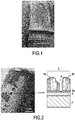
- Certaines zones de ce système peuvent être endommagées en service à haute température par l'érosion, l'impact de particules, l'oxydation, la corrosion et par les aluminosilicates de calcium et de magnésium (« CMAS »). Les photographies fournies aux
figures 1 et 2 montrent l'aspect d'aubes endommagées en service. Ces dégradations peuvent engendrer des disparitions locales de la couche barrière thermique voire de la sous-couche conduisant à une oxydation de la pièce sous-jacente. - Actuellement, il est connu afin de reconstituer une barrière thermique de décaper l'intégralité du revêtement de barrière thermique (même les zones non endommagées) des pièces puis de réaliser un nouveau système barrière thermique. Des pièces dont la barrière thermique a été endommagée peuvent même dans certains cas être mises au rebut.
- Il existe un besoin pour améliorer la durée d'utilisation des pièces revêtues par des barrières thermiques.
- Il existe un besoin pour simplifier et diminuer le coût des procédés de réparation des barrières thermiques endommagées.
- Il existe aussi un besoin pour disposer de nouveaux procédés de réparation des barrières thermiques endommagées.
- A cet effet, l'invention propose, selon un premier aspect, un procédé de réparation localisée d'une barrière thermique endommagée comportant l'étape suivante :
- a) traitement par électrophorèse d'une pièce revêtue d'une barrière thermique endommagée, la pièce étant formée d'un matériau conducteur de l'électricité, la barrière thermique endommagée comportant un matériau céramique et présentant au moins une zone endommagée à réparer, la pièce étant présente dans un électrolyte comportant une suspension de particules dans un milieu liquide, un revêtement céramique étant déposé par électrophorèse dans la zone endommagée afin d'obtenir une barrière thermique réparée destinée à être utilisée à des températures supérieures ou égales à 1000°C.
- Dans l'invention, la pièce est formée d'un matériau conducteur de l'électricité et la barrière thermique endommagée permet la conduction de l'électricité dans la zone endommagée à réparer et donc le dépôt du revêtement céramique par électrophorèse dans cette zone lors de l'étape a). Le revêtement céramique obtenu lors de l'étape a) est formé par le dépôt des particules sur la pièce. Le revêtement céramique peut être majoritairement déposé dans la zone endommagée. En d'autres termes, une masse de revêtement céramique supérieure ou égale à 50% de la masse totale du revêtement céramique déposé lors de l'étape a) peut être déposée dans la zone endommagée. Cette masse de revêtement céramique déposée dans la zone endommagée peut par exemple être supérieure ou égale à 75%, voire à 90%, de la masse totale du revêtement céramique déposé lors de l'étape a). Dans un exemple de réalisation, le revêtement céramique peut être déposé uniquement dans la zone endommagée.
- L'invention permet avantageusement de réparer de manière rapide, peu coûteuse et localisée la barrière thermique endommagée et ainsi d'éviter la mise au rebut de pièces partiellement dégradées ou le décapage complet de la barrière thermique endommagée. L'invention permet, par conséquent, de prolonger la durée de vie des pièces et de limiter le coût de remise en fonctionnement des pièces dont la barrière thermique a été endommagée.
- La possibilité d'une réparation localisée résulte de la mise en œuvre d'un dépôt par électrophorèse à la différence du procédé de dépôt en phase vapeur avec évaporation sous faisceau d'électrons (« electron beam physical vapor déposition » ; EB-PVD) ou de projection plasma (« plasma spraying » ; PS) qui ne permettent pas ou difficilement la réalisation d'une réparation localisée.
- En outre, le procédé de dépôt par électrophorèse présente l'avantage d'être utilisable pour des pièces présentant des géométries complexes.
- La barrière thermique réparée peut être destinée à être utilisée dans un environnement où la température à la surface de la barrière thermique est supérieure ou égale à 1000°C.
- La pièce peut avantageusement être en matériau métallique et, par exemple, comporter du nickel.
- Avantageusement, avant mise en œuvre de l'étape a), la barrière thermique endommagée peut présenter un manque de matière dans la zone endommagée.
- Dans un exemple de réalisation, les particules, éventuellement agglomérées, peuvent présenter une taille moyenne inférieure ou égale à 10 µm.
- Par « taille moyenne », on désigne la dimension donnée par la distribution granulométrique statistique à la moitié de la population, dite D50.
- Par exemple, les particules, à l'état non aggloméré, peuvent avoir une taille moyenne comprise entre 20 nm et 1 µm.
- De telles tailles de particules permettent avantageusement d'obtenir une suspension stable.
- Les particules peuvent ou non avoir été obtenues par voie sol-gel. Ainsi, dans un exemple de réalisation, le procédé peut comporter, avant l'étape a), une étape de formation des particules par mise en œuvre d'un procédé sol-gel. Ces particules peuvent ensuite être dispersées dans le milieu liquide afin de former l'électrolyte.
- Les particules de l'électrolyte peuvent, par exemple, être des particules de zircone yttriée (YSZ ; « Yttria-Stabilized Zirconia ») lesquelles peuvent ou non avoir été obtenues par voie sol-gel. On peut encore utiliser des particules d'oxyde de zirconium. Plus généralement, on peut utiliser pour le dépôt par électrophorèse toutes particules susceptibles de présenter une charge électrique au sein de l'électrolyte (leur permettant ainsi de se déplacer lors de l'application du champ électrique). On peut ainsi, par exemple, utiliser des particules de formule chimique suivante : ZrO2-ReO1.5 (où Re désigne un élément Terre Rare, par exemple : Gd, Sm ou Er), Y2O3, Al2O3, TiO2 ou CeO2.
- Dans un exemple de réalisation, les particules peuvent être formées du même matériau céramique que celui présent dans la barrière thermique endommagée.
- En variante, les particules peuvent être formées d'un matériau différent du matériau céramique présent dans la barrière thermique endommagée. Dans ce cas, le matériau constituant les particules et le matériau céramique de la barrière thermique endommagée sont avantageusement compatibles thermomécaniquement et chimiquement. Par exemple, la différence entre les coefficients d'expansion thermique du matériau céramique présent dans la barrière thermique endommagée et du matériau constituant les particules peut en valeur absolue avantageusement être inférieure ou égale à 2.10-6 K-1.
- L'utilisation d'un matériau différent peut avantageusement permettre d'apporter une propriété supplémentaire, par exemple propriété anti-CMAS ou matériau thermosensible, et ainsi de fonctionnaliser la barrière thermique tout en la réparant.
- Le milieu liquide peut, par exemple, être choisi parmi : les alcools, par exemple l'éthanol ou l'isopropanol, les cétones par exemple l'acétylacétone, l'eau et leurs mélanges.
- Dans un exemple de réalisation, les particules peuvent être présentes dans le milieu liquide, avant le début de l'étape a), en une concentration supérieure ou égale à 0,1 g/L, de préférence supérieure ou égale à 1 g/L.
- De telles valeurs de concentration permettent avantageusement de disposer d'une suspension stable.
- Dans un exemple de réalisation, l'épaisseur du revêtement céramique déposé peut être supérieure ou égale à 50 nm, par exemple supérieure ou égale à 30 µm. Dans un exemple de réalisation, l'épaisseur du revêtement céramique déposé peut être inférieure ou égale à 200 µm.
- Dans un exemple de réalisation, la pièce peut être revêtue d'une couche d'accrochage permettant l'accrochage de la barrière thermique à la pièce et le revêtement céramique peut être déposé sur la couche d'accrochage.
- La couche d'accrochage permet avantageusement d'améliorer l'accrochage de la barrière thermique à la pièce. La couche d'accrochage peut, en outre, avantageusement permettre de protéger la pièce contre l'oxydation et la corrosion.
- La couche d'accrochage peut, par exemple, être métallique.
- Dans une variante, la barrière thermique peut directement être présente sur la pièce. Ainsi, il est possible qu'aucune couche d'accrochage ne soit présente entre la barrière thermique et la pièce.
- Dans un exemple de réalisation, la durée de l'étape a) peut être supérieure ou égale à 1 minute, de préférence à 5 minutes.
- De telles valeurs permettent avantageusement d'améliorer le caractère couvrant et l'homogénéité du revêtement céramique formé.
- Dans un exemple de réalisation, une tension supérieure ou égale à 1 V peut être imposée durant tout ou partie de l'étape a) entre la pièce et une contre-électrode. La tension imposée durant tout ou partie de l'étape a) peut, de préférence, être supérieure ou égale à 50 V.
- De telles valeurs permettent avantageusement d'améliorer le caractère couvrant et l'homogénéité du revêtement céramique formé.
- Dans un exemple de réalisation, la zone endommagée peut, avant l'étape a), avoir été soumise à une étape de décapage.
- La réalisation d'un décapage permet avantageusement d'éliminer les résidus de barrière thermique et les couches d'oxydes éventuellement présents et ainsi d'améliorer le caractère conducteur de l'électricité de la zone endommagée à réparer afin de favoriser la formation du dépôt du revêtement céramique par électrophorèse.
- Le décapage peut être réalisé mécaniquement, par exemple par sablage, ponçage, meulage, jet d'eau haute pression ou par décapage laser.
- En variante, le décapage peut être un décapage chimique, par exemple un décapage électrolytique ou un décapage en milieu acide ou basique.
- Après décapage, la barrière thermique endommagée peut, au début de l'étape a), présenter un manque de matière dans la zone endommagée.
- Dans un exemple de réalisation, le procédé peut comporter, après l'étape a), une étape b) de consolidation par traitement thermique du revêtement céramique déposé.
- L'étape b) peut, par exemple, comporter la soumission de la pièce obtenue après mise en œuvre de l'étape a) à une température supérieure ou égale à 1000°C, par exemple supérieure ou égale à 1100°C.
- Dans un exemple de réalisation, la pièce peut constituer une aube de turbomachine.
- D'autres caractéristiques et avantages de l'invention ressortiront de la description suivante, en référence aux dessins annexés, sur lesquels :
- la
figure 1 est une photographie d'une aube de turbomachine endommagée en service, - la
figure 2 comporte une photographie d'une aube de turbomachine endommagée en service et illustre, de manière schématique et partielle, la structure d'une barrière thermique endommagée, - les
figures 3A et 3B illustrent, de manière schématique et partielle, la mise en œuvre d'un procédé selon l'invention, et - les
figures 4A et 4B sont des photographies représentant respectivement une pièce avant et après traitement par un procédé selon l'invention. - On a représenté à la
figure 2 une pièce 1 par exemple constituée d'un superalliage à base de nickel revêtue d'une couche d'accrochage 2 sur laquelle est présente une barrière thermique endommagée 3. Une couche d'oxyde 2a est présente entre la couche d'accrochage 2 et la barrière thermique 3 endommagée. La couche 2a peut être constituée d'alumine α-Al2O3. La barrière thermique endommagée 3 comporte un matériau céramique et présente une zone endommagée 4 à réparer. - La zone endommagée 4 peut présenter au moins une zone adjacente non endommagée. Dans l'exemple illustré, la zone endommagée 4 est présente entre deux zones adjacentes non endommagées 5a et 5b.
- On a représenté à la
figure 3A la mise en œuvre d'une étape a) selon l'invention. Comme illustré, la pièce 1 portant la barrière thermique endommagée 3 est présente dans un électrolyte 10 comportant une suspension de particules 11 dans un milieu liquide. Les particules 11 peuvent, par exemple, être des particules de zircone yttriée (zircone stabilisée par de l'oxyde d'yttrium). - A titre d'exemple, on décrit ci-dessous les étapes de la synthèse par voie sol-gel d'une poudre de zircone yttriée destinée, dans un exemple de réalisation, à former les particules 11 :
- Mélange d'acétyl-acétone dans du 1-propanol et de propoxyde de zirconium (Zr(OC3H7)4),
- Mélange du mélange obtenu avec une solution de nitrate d'yttrium dans du 1-propanol,
- Mélange du mélange obtenu avec de l'eau et du 1-propanol (10 mol/L) afin d'obtenir un sol,
- Mise à l'étuve du sol à une température de 50°C,
- Séchage évaporatif ou séchage supercritique,
- Calcination à l'air à une température de 700°C.
- La poudre d'oxyde (zircone yttriée) ainsi obtenue est alors mise en suspension dans un milieu liquide constitué par exemple d'isopropanol afin de former l'électrolyte 10.
- La pièce 1 revêtue de la barrière thermique endommagée 3 constitue une électrode du système d'électrophorèse au regard de laquelle est présente une contre-électrode 20. La contre-électrode 20 est, par exemple, en platine. Du fait du caractère conducteur de la pièce 1 et de la zone endommagée 4, un dépôt par électrophorèse est réalisé dans la zone endommagée 4. La zone endommagée 4 est constituée, dans l'exemple illustré, par une région dépourvue de matière. Dans une variante non illustrée, la zone endommagée comporte une première région dépourvue de matière ainsi qu'une deuxième région dans laquelle une couche céramique est présente, l'épaisseur de la couche céramique présente dans la deuxième région étant suffisamment faible pour que cette deuxième région soit conductrice de l'électricité. En variante encore, la zone endommagée est constituée par une région dans laquelle une couche céramique est présente, l'épaisseur de la couche céramique étant suffisamment faible pour que cette région soit conductrice de l'électricité.
- Le dépôt est réalisé préférentiellement dans les zones les plus conductrices (épaisseur de la couche céramique suffisamment faible ou absence totale de couche céramique) car le champ électrique sera relativement élevé dans ces zones.
- On a représenté un exemple de réalisation où la barrière thermique endommagée 3 présente une unique zone endommagée 4 à réparer mais on ne sort pas du cadre de la présente invention si la barrière thermique endommagée présente une pluralité de zones endommagées à réparer. Dans ce cas, chacune des zones endommagées à réparer est conductrice de l'électricité.
- Durant l'étape a), un générateur G impose une différence de potentiel entre la pièce 1 et la contre-électrode 20. Le générateur G est à courant continu ou pulsé. La pièce 1 est polarisée à une charge opposée à celle des particules 11. Du fait de l'application d'un champ électrique entre la pièce 1 et la contre-électrode 20, les particules 11 se déplacent et se déposent sur la pièce 1 pour former un revêtement céramique 6. Le dépôt du revêtement céramique 6 dans la zone endommagée 4 permet d'obtenir une barrière thermique réparée 7. Le dépôt du revêtement céramique 6 dans la zone endommagée 4 induit une diminution progressive de la conductivité électrique de cette zone au cours du temps. En effet, au fur et à mesure du dépôt du revêtement céramique 6, cette zone devient de plus en plus isolante ce qui ralentit voire stoppe la formation du revêtement céramique 6 sur la pièce 1.
- Comme illustré, le revêtement céramique 6 est déposé dans la zone endommagée 4 et recouvre toute la surface de la zone endommagée 4.
- Avantageusement, lors du dépôt du revêtement céramique 6, la barrière thermique endommagée 3 n'est pas recouverte d'un masque présentant une ouverture se superposant avec la zone endommagée 4 à réparer. En outre, il n'est pas nécessaire avant l'étape a) de décaper une partie de la barrière thermique endommagée 3 située en dehors de la zone endommagée 4 à réparer.
- Le revêtement céramique 6 peut présenter une épaisseur e supérieure ou égale à 50 nm, par exemple supérieure ou égale à 30 µm. L'épaisseur e du revêtement céramique 6 correspond à sa plus grande dimension mesurée perpendiculairement à la surface S de la pièce 1 revêtue.
- Après l'étape a), un séchage puis un traitement thermique de consolidation du revêtement céramique 6 peuvent être effectués.
- Une pièce de superalliage base nickel revêtue d'une barrière thermique de zircone stabilisée par de l'oxyde d'yttrium (YSZ) obtenue par procédé de dépôt en phase vapeur avec évaporation sous faisceau d'électrons (« Electron beam physical vapor deposition » ; EB-PVD) a été utilisée. La barrière thermique a tout d'abord été endommagée par jet d'eau. La
figure 4A montre le résultat obtenu après endommagement. - Un dépôt par électrophorèse a été réalisé à partir d'une suspension de poudre YSZ dans l'isopropanol (10 g/L) à une tension de 100V pendant 6 minutes. Une photographie de la pièce après traitement par le procédé selon l'invention est donnée à la
figure 4B . - On constate que l'on obtient un dépôt couvrant et homogène de zircone stabilisée par de l'oxyde d'yttrium dans la toute la zone endommagée.
- L'expression « comportant/contenant un(e) » doit se comprendre comme « comportant/contenant au moins un(e) ».
- L'expression « compris(e) entre ... et ... » ou « allant de ... à ... » doit se comprendre comme incluant les bornes.
Claims (10)
- Procédé de réparation localisée d'une barrière thermique endommagée (3) comportant l'étape suivante :a) traitement par électrophorèse d'une pièce (1) revêtue d'une barrière thermique endommagée (3), la pièce étant formée d'un matériau conducteur de l'électricité, la barrière thermique endommagée (3) comportant un matériau céramique et présentant au moins une zone endommagée (4) à réparer, la pièce (1) étant présente dans un électrolyte (10) comportant une suspension de particules (11) dans un milieu liquide, les particules (11), à l'état non aggloméré, ayant une taille moyenne comprise entre 20 nm et 1 µm, un revêtement céramique (6) étant déposé par électrophorèse dans la zone endommagée (4) afin d'obtenir une barrière thermique réparée (7) destinée à être utilisée à des températures supérieures ou égales à 1000°C,
les particules (11) étant formées d'un matériau différent du matériau céramique présent dans la barrière thermique endommagée (3),
un générateur (G) imposant une différence de potentiel entre la pièce et une contre-électrode (20) durant le traitement par électrophorèse, le générateur générant un courant pulsé durant le traitement par électrophorèse. - Procédé selon la revendication 1, caractérisé en ce que les particules (11) sont présentes dans le milieu liquide, avant le début de l'étape a), en une concentration supérieure ou égale à 0,1 g/L.
- Procédé selon la revendication 1 ou 2, caractérisé en ce que la durée de l'étape a) est supérieure ou égale à 1 minute.
- Procédé selon l'une quelconque des revendications 1 à 3, caractérisé en ce que une tension supérieure ou égale à 1 V est imposée durant tout ou partie de l'étape a) entre la pièce (1) et une contre-électrode (20).
- Procédé selon l'une quelconque des revendications 1 à 4, caractérisé en ce que l'épaisseur e du revêtement céramique déposé est supérieure ou égale à 30 µm.
- Procédé selon l'une quelconque des revendications 1 à 5, caractérisé en ce que la pièce (1) est revêtue d'une couche d'accrochage (2) permettant l'accrochage de la barrière thermique (3 ; 7) à la pièce (1) et en ce que le revêtement céramique (6) est déposé sur la couche d'accrochage (2).
- Procédé selon l'une quelconque des revendications 1 à 6, caractérisé en ce que la zone endommagée (4) a, avant l'étape a), été soumise à une étape de décapage.
- Procédé selon l'une quelconque des revendications 1 à 7, caractérisé en ce qu'il comporte, après l'étape a), une étape b) de consolidation par traitement thermique du revêtement céramique (6) déposé.
- Procédé selon l'une quelconque des revendications 1 à 8, caractérisé en ce que la pièce constitue une aube de turbomachine.
- Procédé selon l'une quelconque des revendications 1 à 9, la barrière thermique endommagée ayant une structure colonnaire.
Applications Claiming Priority (3)
| Application Number | Priority Date | Filing Date | Title |
|---|---|---|---|
| FR1400224 | 2014-01-29 | ||
| PCT/FR2014/053268 WO2015114227A1 (fr) | 2014-01-29 | 2014-12-11 | Procede de reparation localisee d'une barriere thermique endommagee |
| EP14828044.9A EP3099848B1 (fr) | 2014-01-29 | 2014-12-11 | Procede de reparation localisee d'une barriere thermique endommagee |
Related Parent Applications (2)
| Application Number | Title | Priority Date | Filing Date |
|---|---|---|---|
| EP14828044.9A Division EP3099848B1 (fr) | 2014-01-29 | 2014-12-11 | Procede de reparation localisee d'une barriere thermique endommagee |
| EP14828044.9A Division-Into EP3099848B1 (fr) | 2014-01-29 | 2014-12-11 | Procede de reparation localisee d'une barriere thermique endommagee |
Publications (2)
| Publication Number | Publication Date |
|---|---|
| EP3789518A1 true EP3789518A1 (fr) | 2021-03-10 |
| EP3789518B1 EP3789518B1 (fr) | 2023-11-29 |
Family
ID=50976720
Family Applications (2)
| Application Number | Title | Priority Date | Filing Date |
|---|---|---|---|
| EP20203886.5A Active EP3789518B1 (fr) | 2014-01-29 | 2014-12-11 | Procede de reparation localisee d'une barriere thermique endommagee |
| EP14828044.9A Active EP3099848B1 (fr) | 2014-01-29 | 2014-12-11 | Procede de reparation localisee d'une barriere thermique endommagee |
Family Applications After (1)
| Application Number | Title | Priority Date | Filing Date |
|---|---|---|---|
| EP14828044.9A Active EP3099848B1 (fr) | 2014-01-29 | 2014-12-11 | Procede de reparation localisee d'une barriere thermique endommagee |
Country Status (7)
| Country | Link |
|---|---|
| US (1) | US9840914B2 (fr) |
| EP (2) | EP3789518B1 (fr) |
| CN (1) | CN106414813B (fr) |
| BR (1) | BR112016017562B1 (fr) |
| CA (1) | CA2938031C (fr) |
| RU (1) | RU2678347C2 (fr) |
| WO (1) | WO2015114227A1 (fr) |
Families Citing this family (4)
| Publication number | Priority date | Publication date | Assignee | Title |
|---|---|---|---|---|
| FR3073866B1 (fr) * | 2017-11-21 | 2019-11-29 | Safran Helicopter Engines | Procede de fabrication d'une barriere thermique sur une piece d'une turbomachine |
| CN110129859B (zh) * | 2018-02-08 | 2021-09-21 | 通用电气公司 | 掩蔽元件中的孔并对元件进行处理的方法 |
| FR3099935B1 (fr) * | 2019-08-12 | 2021-09-10 | Safran Aircraft Engines | Procédé de revêtement d’une pièce de turbomachine |
| US12139808B2 (en) * | 2022-01-12 | 2024-11-12 | General Electric Company | Formation of a barrier coating using electrophoretic deposition of a slurry |
Citations (6)
| Publication number | Priority date | Publication date | Assignee | Title |
|---|---|---|---|---|
| FR2546911A1 (fr) * | 1983-06-03 | 1984-12-07 | Thuringia Sonneberg Veb | Procede pour la realisation d'une couche massive par electrophorese |
| US5723078A (en) * | 1996-05-24 | 1998-03-03 | General Electric Company | Method for repairing a thermal barrier coating |
| DE10335406A1 (de) * | 2003-08-01 | 2005-02-17 | Mtu Aero Engines Gmbh | Verfahren zum Reparieren von Wärmedämmschichten mit lokalen Beschädigungen |
| US20070119713A1 (en) * | 2005-11-30 | 2007-05-31 | General Electric Company | Methods for applying mitigation coatings, and related articles |
| WO2008029979A1 (fr) * | 2006-09-09 | 2008-03-13 | Korea Atomic Energy Research Institute | Procédé de réparation de la piqûration et des fissures des métaux ou alliages par dépôt électrophorétique de nanoparticules |
| EP2000557A1 (fr) * | 2007-06-04 | 2008-12-10 | United Technologies Corporation | Barrière contre l'érosion pour revêtements de barrière thermique |
Family Cites Families (3)
| Publication number | Priority date | Publication date | Assignee | Title |
|---|---|---|---|---|
| SU1730209A1 (ru) * | 1988-09-23 | 1992-04-30 | Предприятие П/Я А-7555 | Установка дл электрофоретических покрытий |
| FR2827311B1 (fr) * | 2001-07-12 | 2003-09-19 | Snecma Moteurs | Procede de reparation locale de pieces revetues d'une barriere thermique |
| US20070087129A1 (en) * | 2005-10-19 | 2007-04-19 | Blankenship Donn R | Methods for repairing a workpiece |
-
2014
- 2014-12-11 EP EP20203886.5A patent/EP3789518B1/fr active Active
- 2014-12-11 EP EP14828044.9A patent/EP3099848B1/fr active Active
- 2014-12-11 CN CN201480074456.0A patent/CN106414813B/zh active Active
- 2014-12-11 CA CA2938031A patent/CA2938031C/fr active Active
- 2014-12-11 WO PCT/FR2014/053268 patent/WO2015114227A1/fr not_active Ceased
- 2014-12-11 BR BR112016017562-0A patent/BR112016017562B1/pt active IP Right Grant
- 2014-12-11 US US15/115,068 patent/US9840914B2/en active Active
- 2014-12-11 RU RU2016135017A patent/RU2678347C2/ru active
Patent Citations (6)
| Publication number | Priority date | Publication date | Assignee | Title |
|---|---|---|---|---|
| FR2546911A1 (fr) * | 1983-06-03 | 1984-12-07 | Thuringia Sonneberg Veb | Procede pour la realisation d'une couche massive par electrophorese |
| US5723078A (en) * | 1996-05-24 | 1998-03-03 | General Electric Company | Method for repairing a thermal barrier coating |
| DE10335406A1 (de) * | 2003-08-01 | 2005-02-17 | Mtu Aero Engines Gmbh | Verfahren zum Reparieren von Wärmedämmschichten mit lokalen Beschädigungen |
| US20070119713A1 (en) * | 2005-11-30 | 2007-05-31 | General Electric Company | Methods for applying mitigation coatings, and related articles |
| WO2008029979A1 (fr) * | 2006-09-09 | 2008-03-13 | Korea Atomic Energy Research Institute | Procédé de réparation de la piqûration et des fissures des métaux ou alliages par dépôt électrophorétique de nanoparticules |
| EP2000557A1 (fr) * | 2007-06-04 | 2008-12-10 | United Technologies Corporation | Barrière contre l'érosion pour revêtements de barrière thermique |
Also Published As
| Publication number | Publication date |
|---|---|
| US20160348509A1 (en) | 2016-12-01 |
| CN106414813A (zh) | 2017-02-15 |
| CN106414813B (zh) | 2019-04-30 |
| RU2016135017A (ru) | 2018-03-05 |
| EP3099848A1 (fr) | 2016-12-07 |
| EP3789518B1 (fr) | 2023-11-29 |
| WO2015114227A1 (fr) | 2015-08-06 |
| EP3099848B1 (fr) | 2021-08-25 |
| RU2016135017A3 (fr) | 2018-08-22 |
| US9840914B2 (en) | 2017-12-12 |
| BR112016017562A2 (fr) | 2017-08-08 |
| BR112016017562B1 (pt) | 2022-04-12 |
| CA2938031C (fr) | 2022-05-10 |
| CA2938031A1 (fr) | 2015-08-06 |
| RU2678347C2 (ru) | 2019-01-28 |
Similar Documents
| Publication | Publication Date | Title |
|---|---|---|
| EP3099848B1 (fr) | Procede de reparation localisee d'une barriere thermique endommagee | |
| CA2792518C (fr) | Methode de fabrication d'une protecton de barriere thermique et revetement multicouche apte a former une barriere thermique | |
| CA2931927C (fr) | Procede de reparation locale de barrieres thermiques | |
| CA2828792C (fr) | Procede de realisation d'une barriere thermique dans un systeme multicouche de protection de piece metallique et piece munie d'un tel systeme de protection | |
| FR3025930A1 (fr) | Gaines de combustible nucleaire, procedes de fabrication et utilisation contre l'oxydation. | |
| EP2882551B1 (fr) | Revetement en materiau abradable a faible rugosite de surface | |
| CA2769196C (fr) | Piece comportant un substrat portant une couche de revetement ceramique | |
| EP3707297B1 (fr) | Procede de fabrication d'une barriere thermique sur une piece d'une turbomachine | |
| FR2946663A1 (fr) | Revetement thermique, piece thermomecanique comportant un tel revetement thermique, turbomachine, moteur d'aeronef, d'astronef ou de fusee comportant une telle piece thermomecanique | |
| WO2017093648A1 (fr) | Secteur annulaire hybride à revêtement de protection tolérant à la touche | |
| WO2010092298A1 (fr) | Procede de depot d'une couche de protection sur une piece. | |
| EP3980584B1 (fr) | Procédé de fabrication d'une pièce résistante au feu d'un système de conditionnement d'air et pièce obtenue par un tel procédé | |
| CA2803160A1 (fr) | Barriere thermique pour aube de turbine, a structure colonnaire avec des colonnes espacees | |
| EP3669013B1 (fr) | Procédé de fabrication par pulvérisation cathodique magnétron d'un électrolyte pour cellules électrochimiques à oxyde solide | |
| FR3065968A1 (fr) | Piece de turbine en superalliage et procede de fabrication associe par bombardement de particules chargees | |
| WO2023094752A1 (fr) | Procédé de revêtement par électrophorèse d'une pièce en matériau composite à matrice céramique par une barrière environnementale | |
| FR3085870A1 (fr) | Procede d'assemblage d'une piece de metal et d'une piece de ceramique, et dispositif electrique, en particulier capteur capacitif, realise par le procede | |
| FR2949236A1 (fr) | Procede d'implantation ionique pour la realisation d'une surface hydrophobe | |
| FR3163369A1 (fr) | Pièce comprenant un substrat et une barrière environnementale et procédés associés | |
| FR3085872A1 (fr) | Procede d'extraction d'un corps etranger niche dans une pale de distributeur haute pression |
Legal Events
| Date | Code | Title | Description |
|---|---|---|---|
| PUAI | Public reference made under article 153(3) epc to a published international application that has entered the european phase |
Free format text: ORIGINAL CODE: 0009012 |
|
| STAA | Information on the status of an ep patent application or granted ep patent |
Free format text: STATUS: REQUEST FOR EXAMINATION WAS MADE |
|
| 17P | Request for examination filed |
Effective date: 20201026 |
|
| AC | Divisional application: reference to earlier application |
Ref document number: 3099848 Country of ref document: EP Kind code of ref document: P |
|
| AK | Designated contracting states |
Kind code of ref document: A1 Designated state(s): AL AT BE BG CH CY CZ DE DK EE ES FI FR GB GR HR HU IE IS IT LI LT LU LV MC MK MT NL NO PL PT RO RS SE SI SK SM TR |
|
| GRAP | Despatch of communication of intention to grant a patent |
Free format text: ORIGINAL CODE: EPIDOSNIGR1 |
|
| STAA | Information on the status of an ep patent application or granted ep patent |
Free format text: STATUS: GRANT OF PATENT IS INTENDED |
|
| RIC1 | Information provided on ipc code assigned before grant |
Ipc: F01D 5/00 20060101ALI20230822BHEP Ipc: C25D 13/12 20060101ALI20230822BHEP Ipc: C25D 13/20 20060101ALI20230822BHEP Ipc: F01D 5/28 20060101ALI20230822BHEP Ipc: C25D 13/18 20060101ALI20230822BHEP Ipc: C25D 13/22 20060101ALI20230822BHEP Ipc: C25D 13/02 20060101AFI20230822BHEP |
|
| INTG | Intention to grant announced |
Effective date: 20230922 |
|
| GRAS | Grant fee paid |
Free format text: ORIGINAL CODE: EPIDOSNIGR3 |
|
| GRAA | (expected) grant |
Free format text: ORIGINAL CODE: 0009210 |
|
| STAA | Information on the status of an ep patent application or granted ep patent |
Free format text: STATUS: THE PATENT HAS BEEN GRANTED |
|
| AC | Divisional application: reference to earlier application |
Ref document number: 3099848 Country of ref document: EP Kind code of ref document: P |
|
| AK | Designated contracting states |
Kind code of ref document: B1 Designated state(s): AL AT BE BG CH CY CZ DE DK EE ES FI FR GB GR HR HU IE IS IT LI LT LU LV MC MK MT NL NO PL PT RO RS SE SI SK SM TR |
|
| REG | Reference to a national code |
Ref country code: GB Ref legal event code: FG4D Free format text: NOT ENGLISH |
|
| REG | Reference to a national code |
Ref country code: CH Ref legal event code: EP |
|
| REG | Reference to a national code |
Ref country code: DE Ref legal event code: R096 Ref document number: 602014089025 Country of ref document: DE |
|
| REG | Reference to a national code |
Ref country code: IE Ref legal event code: FG4D Free format text: LANGUAGE OF EP DOCUMENT: FRENCH |
|
| REG | Reference to a national code |
Ref country code: LT Ref legal event code: MG9D |
|
| REG | Reference to a national code |
Ref country code: NL Ref legal event code: MP Effective date: 20231129 |
|
| PG25 | Lapsed in a contracting state [announced via postgrant information from national office to epo] |
Ref country code: GR Free format text: LAPSE BECAUSE OF FAILURE TO SUBMIT A TRANSLATION OF THE DESCRIPTION OR TO PAY THE FEE WITHIN THE PRESCRIBED TIME-LIMIT Effective date: 20240301 |
|
| PG25 | Lapsed in a contracting state [announced via postgrant information from national office to epo] |
Ref country code: IS Free format text: LAPSE BECAUSE OF FAILURE TO SUBMIT A TRANSLATION OF THE DESCRIPTION OR TO PAY THE FEE WITHIN THE PRESCRIBED TIME-LIMIT Effective date: 20240329 |
|
| PG25 | Lapsed in a contracting state [announced via postgrant information from national office to epo] |
Ref country code: LT Free format text: LAPSE BECAUSE OF FAILURE TO SUBMIT A TRANSLATION OF THE DESCRIPTION OR TO PAY THE FEE WITHIN THE PRESCRIBED TIME-LIMIT Effective date: 20231129 |
|
| PG25 | Lapsed in a contracting state [announced via postgrant information from national office to epo] |
Ref country code: ES Free format text: LAPSE BECAUSE OF FAILURE TO SUBMIT A TRANSLATION OF THE DESCRIPTION OR TO PAY THE FEE WITHIN THE PRESCRIBED TIME-LIMIT Effective date: 20231129 |
|
| PG25 | Lapsed in a contracting state [announced via postgrant information from national office to epo] |
Ref country code: LT Free format text: LAPSE BECAUSE OF FAILURE TO SUBMIT A TRANSLATION OF THE DESCRIPTION OR TO PAY THE FEE WITHIN THE PRESCRIBED TIME-LIMIT Effective date: 20231129 Ref country code: IS Free format text: LAPSE BECAUSE OF FAILURE TO SUBMIT A TRANSLATION OF THE DESCRIPTION OR TO PAY THE FEE WITHIN THE PRESCRIBED TIME-LIMIT Effective date: 20240329 Ref country code: GR Free format text: LAPSE BECAUSE OF FAILURE TO SUBMIT A TRANSLATION OF THE DESCRIPTION OR TO PAY THE FEE WITHIN THE PRESCRIBED TIME-LIMIT Effective date: 20240301 Ref country code: ES Free format text: LAPSE BECAUSE OF FAILURE TO SUBMIT A TRANSLATION OF THE DESCRIPTION OR TO PAY THE FEE WITHIN THE PRESCRIBED TIME-LIMIT Effective date: 20231129 Ref country code: BG Free format text: LAPSE BECAUSE OF FAILURE TO SUBMIT A TRANSLATION OF THE DESCRIPTION OR TO PAY THE FEE WITHIN THE PRESCRIBED TIME-LIMIT Effective date: 20240229 |
|
| REG | Reference to a national code |
Ref country code: AT Ref legal event code: MK05 Ref document number: 1636192 Country of ref document: AT Kind code of ref document: T Effective date: 20231129 |
|
| PG25 | Lapsed in a contracting state [announced via postgrant information from national office to epo] |
Ref country code: NL Free format text: LAPSE BECAUSE OF FAILURE TO SUBMIT A TRANSLATION OF THE DESCRIPTION OR TO PAY THE FEE WITHIN THE PRESCRIBED TIME-LIMIT Effective date: 20231129 |
|
| PG25 | Lapsed in a contracting state [announced via postgrant information from national office to epo] |
Ref country code: SE Free format text: LAPSE BECAUSE OF FAILURE TO SUBMIT A TRANSLATION OF THE DESCRIPTION OR TO PAY THE FEE WITHIN THE PRESCRIBED TIME-LIMIT Effective date: 20231129 Ref country code: RS Free format text: LAPSE BECAUSE OF FAILURE TO SUBMIT A TRANSLATION OF THE DESCRIPTION OR TO PAY THE FEE WITHIN THE PRESCRIBED TIME-LIMIT Effective date: 20231129 Ref country code: PL Free format text: LAPSE BECAUSE OF FAILURE TO SUBMIT A TRANSLATION OF THE DESCRIPTION OR TO PAY THE FEE WITHIN THE PRESCRIBED TIME-LIMIT Effective date: 20231129 Ref country code: NO Free format text: LAPSE BECAUSE OF FAILURE TO SUBMIT A TRANSLATION OF THE DESCRIPTION OR TO PAY THE FEE WITHIN THE PRESCRIBED TIME-LIMIT Effective date: 20240229 Ref country code: NL Free format text: LAPSE BECAUSE OF FAILURE TO SUBMIT A TRANSLATION OF THE DESCRIPTION OR TO PAY THE FEE WITHIN THE PRESCRIBED TIME-LIMIT Effective date: 20231129 Ref country code: LV Free format text: LAPSE BECAUSE OF FAILURE TO SUBMIT A TRANSLATION OF THE DESCRIPTION OR TO PAY THE FEE WITHIN THE PRESCRIBED TIME-LIMIT Effective date: 20231129 Ref country code: HR Free format text: LAPSE BECAUSE OF FAILURE TO SUBMIT A TRANSLATION OF THE DESCRIPTION OR TO PAY THE FEE WITHIN THE PRESCRIBED TIME-LIMIT Effective date: 20231129 |
|
| PG25 | Lapsed in a contracting state [announced via postgrant information from national office to epo] |
Ref country code: DK Free format text: LAPSE BECAUSE OF FAILURE TO SUBMIT A TRANSLATION OF THE DESCRIPTION OR TO PAY THE FEE WITHIN THE PRESCRIBED TIME-LIMIT Effective date: 20231129 |
|
| PG25 | Lapsed in a contracting state [announced via postgrant information from national office to epo] |
Ref country code: CZ Free format text: LAPSE BECAUSE OF FAILURE TO SUBMIT A TRANSLATION OF THE DESCRIPTION OR TO PAY THE FEE WITHIN THE PRESCRIBED TIME-LIMIT Effective date: 20231129 Ref country code: AT Free format text: LAPSE BECAUSE OF FAILURE TO SUBMIT A TRANSLATION OF THE DESCRIPTION OR TO PAY THE FEE WITHIN THE PRESCRIBED TIME-LIMIT Effective date: 20231129 |
|
| PG25 | Lapsed in a contracting state [announced via postgrant information from national office to epo] |
Ref country code: SK Free format text: LAPSE BECAUSE OF FAILURE TO SUBMIT A TRANSLATION OF THE DESCRIPTION OR TO PAY THE FEE WITHIN THE PRESCRIBED TIME-LIMIT Effective date: 20231129 |
|
| PG25 | Lapsed in a contracting state [announced via postgrant information from national office to epo] |
Ref country code: SM Free format text: LAPSE BECAUSE OF FAILURE TO SUBMIT A TRANSLATION OF THE DESCRIPTION OR TO PAY THE FEE WITHIN THE PRESCRIBED TIME-LIMIT Effective date: 20231129 Ref country code: SK Free format text: LAPSE BECAUSE OF FAILURE TO SUBMIT A TRANSLATION OF THE DESCRIPTION OR TO PAY THE FEE WITHIN THE PRESCRIBED TIME-LIMIT Effective date: 20231129 Ref country code: RO Free format text: LAPSE BECAUSE OF FAILURE TO SUBMIT A TRANSLATION OF THE DESCRIPTION OR TO PAY THE FEE WITHIN THE PRESCRIBED TIME-LIMIT Effective date: 20231129 Ref country code: IT Free format text: LAPSE BECAUSE OF FAILURE TO SUBMIT A TRANSLATION OF THE DESCRIPTION OR TO PAY THE FEE WITHIN THE PRESCRIBED TIME-LIMIT Effective date: 20231129 Ref country code: EE Free format text: LAPSE BECAUSE OF FAILURE TO SUBMIT A TRANSLATION OF THE DESCRIPTION OR TO PAY THE FEE WITHIN THE PRESCRIBED TIME-LIMIT Effective date: 20231129 Ref country code: DK Free format text: LAPSE BECAUSE OF FAILURE TO SUBMIT A TRANSLATION OF THE DESCRIPTION OR TO PAY THE FEE WITHIN THE PRESCRIBED TIME-LIMIT Effective date: 20231129 Ref country code: CZ Free format text: LAPSE BECAUSE OF FAILURE TO SUBMIT A TRANSLATION OF THE DESCRIPTION OR TO PAY THE FEE WITHIN THE PRESCRIBED TIME-LIMIT Effective date: 20231129 Ref country code: AT Free format text: LAPSE BECAUSE OF FAILURE TO SUBMIT A TRANSLATION OF THE DESCRIPTION OR TO PAY THE FEE WITHIN THE PRESCRIBED TIME-LIMIT Effective date: 20231129 |
|
| REG | Reference to a national code |
Ref country code: CH Ref legal event code: PL |
|
| PG25 | Lapsed in a contracting state [announced via postgrant information from national office to epo] |
Ref country code: PT Free format text: LAPSE BECAUSE OF FAILURE TO SUBMIT A TRANSLATION OF THE DESCRIPTION OR TO PAY THE FEE WITHIN THE PRESCRIBED TIME-LIMIT Effective date: 20240401 |
|
| PG25 | Lapsed in a contracting state [announced via postgrant information from national office to epo] |
Ref country code: LU Free format text: LAPSE BECAUSE OF NON-PAYMENT OF DUE FEES Effective date: 20231211 |
|
| PG25 | Lapsed in a contracting state [announced via postgrant information from national office to epo] |
Ref country code: MC Free format text: LAPSE BECAUSE OF FAILURE TO SUBMIT A TRANSLATION OF THE DESCRIPTION OR TO PAY THE FEE WITHIN THE PRESCRIBED TIME-LIMIT Effective date: 20231129 |
|
| REG | Reference to a national code |
Ref country code: BE Ref legal event code: MM Effective date: 20231231 |
|
| PG25 | Lapsed in a contracting state [announced via postgrant information from national office to epo] |
Ref country code: PT Free format text: LAPSE BECAUSE OF FAILURE TO SUBMIT A TRANSLATION OF THE DESCRIPTION OR TO PAY THE FEE WITHIN THE PRESCRIBED TIME-LIMIT Effective date: 20240401 Ref country code: MC Free format text: LAPSE BECAUSE OF FAILURE TO SUBMIT A TRANSLATION OF THE DESCRIPTION OR TO PAY THE FEE WITHIN THE PRESCRIBED TIME-LIMIT Effective date: 20231129 Ref country code: LU Free format text: LAPSE BECAUSE OF NON-PAYMENT OF DUE FEES Effective date: 20231211 |
|
| REG | Reference to a national code |
Ref country code: DE Ref legal event code: R097 Ref document number: 602014089025 Country of ref document: DE |
|
| PLBE | No opposition filed within time limit |
Free format text: ORIGINAL CODE: 0009261 |
|
| STAA | Information on the status of an ep patent application or granted ep patent |
Free format text: STATUS: NO OPPOSITION FILED WITHIN TIME LIMIT |
|
| REG | Reference to a national code |
Ref country code: IE Ref legal event code: MM4A |
|
| PG25 | Lapsed in a contracting state [announced via postgrant information from national office to epo] |
Ref country code: IE Free format text: LAPSE BECAUSE OF NON-PAYMENT OF DUE FEES Effective date: 20231211 |
|
| PG25 | Lapsed in a contracting state [announced via postgrant information from national office to epo] |
Ref country code: BE Free format text: LAPSE BECAUSE OF NON-PAYMENT OF DUE FEES Effective date: 20231231 |
|
| PG25 | Lapsed in a contracting state [announced via postgrant information from national office to epo] |
Ref country code: CH Free format text: LAPSE BECAUSE OF NON-PAYMENT OF DUE FEES Effective date: 20231231 |
|
| PG25 | Lapsed in a contracting state [announced via postgrant information from national office to epo] |
Ref country code: SI Free format text: LAPSE BECAUSE OF FAILURE TO SUBMIT A TRANSLATION OF THE DESCRIPTION OR TO PAY THE FEE WITHIN THE PRESCRIBED TIME-LIMIT Effective date: 20231129 |
|
| PG25 | Lapsed in a contracting state [announced via postgrant information from national office to epo] |
Ref country code: SI Free format text: LAPSE BECAUSE OF FAILURE TO SUBMIT A TRANSLATION OF THE DESCRIPTION OR TO PAY THE FEE WITHIN THE PRESCRIBED TIME-LIMIT Effective date: 20231129 Ref country code: IE Free format text: LAPSE BECAUSE OF NON-PAYMENT OF DUE FEES Effective date: 20231211 Ref country code: CH Free format text: LAPSE BECAUSE OF NON-PAYMENT OF DUE FEES Effective date: 20231231 Ref country code: BE Free format text: LAPSE BECAUSE OF NON-PAYMENT OF DUE FEES Effective date: 20231231 |
|
| 26N | No opposition filed |
Effective date: 20240830 |
|
| PG25 | Lapsed in a contracting state [announced via postgrant information from national office to epo] |
Ref country code: FI Free format text: LAPSE BECAUSE OF FAILURE TO SUBMIT A TRANSLATION OF THE DESCRIPTION OR TO PAY THE FEE WITHIN THE PRESCRIBED TIME-LIMIT Effective date: 20231129 |
|
| PG25 | Lapsed in a contracting state [announced via postgrant information from national office to epo] |
Ref country code: CY Free format text: LAPSE BECAUSE OF FAILURE TO SUBMIT A TRANSLATION OF THE DESCRIPTION OR TO PAY THE FEE WITHIN THE PRESCRIBED TIME-LIMIT; INVALID AB INITIO Effective date: 20141211 |
|
| PG25 | Lapsed in a contracting state [announced via postgrant information from national office to epo] |
Ref country code: HU Free format text: LAPSE BECAUSE OF FAILURE TO SUBMIT A TRANSLATION OF THE DESCRIPTION OR TO PAY THE FEE WITHIN THE PRESCRIBED TIME-LIMIT; INVALID AB INITIO Effective date: 20141211 |
|
| PG25 | Lapsed in a contracting state [announced via postgrant information from national office to epo] |
Ref country code: TR Free format text: LAPSE BECAUSE OF FAILURE TO SUBMIT A TRANSLATION OF THE DESCRIPTION OR TO PAY THE FEE WITHIN THE PRESCRIBED TIME-LIMIT Effective date: 20231129 |
|
| PGFP | Annual fee paid to national office [announced via postgrant information from national office to epo] |
Ref country code: GB Payment date: 20251229 Year of fee payment: 12 |
|
| PGFP | Annual fee paid to national office [announced via postgrant information from national office to epo] |
Ref country code: FR Payment date: 20251222 Year of fee payment: 12 |
|
| PGFP | Annual fee paid to national office [announced via postgrant information from national office to epo] |
Ref country code: DE Payment date: 20251222 Year of fee payment: 12 |