EP3789340B1 - Dispenser actuator assembly - Google Patents
Dispenser actuator assembly Download PDFInfo
- Publication number
- EP3789340B1 EP3789340B1 EP20194721.5A EP20194721A EP3789340B1 EP 3789340 B1 EP3789340 B1 EP 3789340B1 EP 20194721 A EP20194721 A EP 20194721A EP 3789340 B1 EP3789340 B1 EP 3789340B1
- Authority
- EP
- European Patent Office
- Prior art keywords
- dispenser
- assembly
- actuator assembly
- glass ampoule
- base member
- Prior art date
- Legal status (The legal status is an assumption and is not a legal conclusion. Google has not performed a legal analysis and makes no representation as to the accuracy of the status listed.)
- Active
Links
Images


Classifications
-
- A—HUMAN NECESSITIES
- A45—HAND OR TRAVELLING ARTICLES
- A45D—HAIRDRESSING OR SHAVING EQUIPMENT; EQUIPMENT FOR COSMETICS OR COSMETIC TREATMENTS, e.g. FOR MANICURING OR PEDICURING
- A45D40/00—Casings or accessories specially adapted for storing or handling solid or pasty toiletry or cosmetic substances, e.g. shaving soaps or lipsticks
- A45D40/0087—Casings or accessories specially adapted for storing or handling solid or pasty toiletry or cosmetic substances, e.g. shaving soaps or lipsticks for samples
-
- A—HUMAN NECESSITIES
- A45—HAND OR TRAVELLING ARTICLES
- A45D—HAIRDRESSING OR SHAVING EQUIPMENT; EQUIPMENT FOR COSMETICS OR COSMETIC TREATMENTS, e.g. FOR MANICURING OR PEDICURING
- A45D19/00—Devices for washing the hair or the scalp; Similar devices for colouring the hair
- A45D19/02—Hand-actuated implements, e.g. hand-actuated spray heads
-
- A—HUMAN NECESSITIES
- A45—HAND OR TRAVELLING ARTICLES
- A45D—HAIRDRESSING OR SHAVING EQUIPMENT; EQUIPMENT FOR COSMETICS OR COSMETIC TREATMENTS, e.g. FOR MANICURING OR PEDICURING
- A45D34/00—Containers or accessories specially adapted for handling liquid toiletry or cosmetic substances, e.g. perfumes
- A45D34/04—Appliances specially adapted for applying liquid, e.g. using roller or ball
-
- A—HUMAN NECESSITIES
- A61—MEDICAL OR VETERINARY SCIENCE; HYGIENE
- A61B—DIAGNOSIS; SURGERY; IDENTIFICATION
- A61B17/00—Surgical instruments, devices or methods
- A61B17/00491—Surgical glue applicators
-
- A—HUMAN NECESSITIES
- A61—MEDICAL OR VETERINARY SCIENCE; HYGIENE
- A61M—DEVICES FOR INTRODUCING MEDIA INTO, OR ONTO, THE BODY; DEVICES FOR TRANSDUCING BODY MEDIA OR FOR TAKING MEDIA FROM THE BODY; DEVICES FOR PRODUCING OR ENDING SLEEP OR STUPOR
- A61M35/00—Devices for applying media, e.g. remedies, on the human body
- A61M35/003—Portable hand-held applicators having means for dispensing or spreading integral media
-
- B—PERFORMING OPERATIONS; TRANSPORTING
- B05—SPRAYING OR ATOMISING IN GENERAL; APPLYING FLUENT MATERIALS TO SURFACES, IN GENERAL
- B05B—SPRAYING APPARATUS; ATOMISING APPARATUS; NOZZLES
- B05B11/00—Single-unit hand-held apparatus in which flow of contents is produced by the muscular force of the operator at the moment of use
- B05B11/01—Single-unit hand-held apparatus in which flow of contents is produced by the muscular force of the operator at the moment of use characterised by the means producing the flow
- B05B11/04—Deformable containers producing the flow, e.g. squeeze bottles
- B05B11/048—Deformable containers producing the flow, e.g. squeeze bottles characterised by the container, e.g. this latter being surrounded by an enclosure, or the means for deforming it
-
- B—PERFORMING OPERATIONS; TRANSPORTING
- B67—OPENING, CLOSING OR CLEANING BOTTLES, JARS OR SIMILAR CONTAINERS; LIQUID HANDLING
- B67B—APPLYING CLOSURE MEMBERS TO BOTTLES JARS, OR SIMILAR CONTAINERS; OPENING CLOSED CONTAINERS
- B67B7/00—Hand- or power-operated devices for opening closed containers
- B67B7/92—Hand- or power-operated devices for opening closed containers by breaking, e.g. for ampoules
-
- A—HUMAN NECESSITIES
- A45—HAND OR TRAVELLING ARTICLES
- A45D—HAIRDRESSING OR SHAVING EQUIPMENT; EQUIPMENT FOR COSMETICS OR COSMETIC TREATMENTS, e.g. FOR MANICURING OR PEDICURING
- A45D2200/00—Details not otherwise provided for in A45D
- A45D2200/05—Details of containers
- A45D2200/053—Transparent containers
-
- A—HUMAN NECESSITIES
- A45—HAND OR TRAVELLING ARTICLES
- A45D—HAIRDRESSING OR SHAVING EQUIPMENT; EQUIPMENT FOR COSMETICS OR COSMETIC TREATMENTS, e.g. FOR MANICURING OR PEDICURING
- A45D2200/00—Details not otherwise provided for in A45D
- A45D2200/05—Details of containers
- A45D2200/058—Means for mixing different substances prior to application
-
- A—HUMAN NECESSITIES
- A45—HAND OR TRAVELLING ARTICLES
- A45D—HAIRDRESSING OR SHAVING EQUIPMENT; EQUIPMENT FOR COSMETICS OR COSMETIC TREATMENTS, e.g. FOR MANICURING OR PEDICURING
- A45D2200/00—Details not otherwise provided for in A45D
- A45D2200/10—Details of applicators
- A45D2200/1009—Applicators comprising a pad, tissue, sponge, or the like
-
- A—HUMAN NECESSITIES
- A61—MEDICAL OR VETERINARY SCIENCE; HYGIENE
- A61B—DIAGNOSIS; SURGERY; IDENTIFICATION
- A61B17/00—Surgical instruments, devices or methods
- A61B17/00491—Surgical glue applicators
- A61B2017/00495—Surgical glue applicators for two-component glue
-
- A—HUMAN NECESSITIES
- A61—MEDICAL OR VETERINARY SCIENCE; HYGIENE
- A61B—DIAGNOSIS; SURGERY; IDENTIFICATION
- A61B90/00—Instruments, implements or accessories specially adapted for surgery or diagnosis and not covered by any of the groups A61B1/00 - A61B50/00, e.g. for luxation treatment or for protecting wound edges
- A61B90/03—Automatic limiting or abutting means, e.g. for safety
- A61B2090/037—Automatic limiting or abutting means, e.g. for safety with a frangible part, e.g. by reduced diameter
Definitions
- FIGS. 5-15 show the base member 102 of the dispenser actuator assembly 100.
- the base member 102 is generally a rounded member that fits around at least a portion of the glass ampoule assembly 10.
- the base member 102 is further an annular member that in one exemplary embodiment is dimensioned to fit over the dispenser or glass ampoule assembly 10 to achieve a mount between the base member 102 and the glass ampoule assembly 10 as described in greater detail below.
- the ribs 266 are spaced along the inner surface 264 and in an exemplary embodiment, may be placed at a 12 o'clock position, a 3 o'clock position, a 6 o'clock position and a 9 o'clock position.
- the ribs 266 each have a distal end that will engage an outer surface of the outer container 14 of the ampoule 10 as will be described in greater detail below.
- the inner surface 264 also has a tapered segment at a proximal end of the outer member 260 extending away from inner member 262. It is understood that the ribs 266 have a generally longitudinal configuration extending linearly along the outer member 260. In an alternative embodiment, the ribs 266 can take the form of circumferential ribs. It is further understood that the outer member 260 and the inner member are circumjacent to one another and generally have concentric configurations around a longitudinal axis of the assembly.
- the dispenser can be used in many different applications including mechanical, chemical, electrical or biomedical uses.
- the dispenser can dispense any variety of flowable materials including liquids and powders, and further including a liquid and a powder, two or more powders, or two or more liquids.
- the dispenser may be used as part of 2-part system (mix before use) including a liquid with a powder, a liquid with a liquid, a powder with a powder, or sealed inside another tube or product container or partially sealed, connected or attached to another container.
- the dispenser may also be used as part of a plunger dispensing system.
Landscapes
- Health & Medical Sciences (AREA)
- Life Sciences & Earth Sciences (AREA)
- Engineering & Computer Science (AREA)
- Veterinary Medicine (AREA)
- General Health & Medical Sciences (AREA)
- Biomedical Technology (AREA)
- Heart & Thoracic Surgery (AREA)
- Surgery (AREA)
- Public Health (AREA)
- Animal Behavior & Ethology (AREA)
- Medical Informatics (AREA)
- Molecular Biology (AREA)
- Nuclear Medicine, Radiotherapy & Molecular Imaging (AREA)
- Mechanical Engineering (AREA)
- Anesthesiology (AREA)
- Hematology (AREA)
- Medical Preparation Storing Or Oral Administration Devices (AREA)
Description
- The present application claims the benefit of
U.S. Patent Application No. 62/895,593, filed on September 4, 2019 U.S. Patent Application No. 16/598,913, filed on October 10, 2019 - The invention relates generally to an actuator assembly for a dispenser and more particularly, to an dispenser actuator assembly having a base member having an integral applicator and configured to mount to a crushable glass ampoule assembly wherein an actuator assembly in the form of a first actuator arm and a second actuator arm are operably connected to the base member and dimensioned to crush the glass ampoule assembly.
- Dispensers such as glass ampoule assemblies are well known in the art and are often designed to be single-use disposable dispensers. A glass ampoule assembly typically includes a rupturable container such as a glass ampoule that contains a flowable material to be dispensed. The glass ampoule is contained in an outer container that may be made from a plastic material and having an open end and a closed end. The glass ampoule assembly may further include an applicator such as a swab that fits in the open end of the outer container. The applicator assists in dispensing the flowable material after the glass ampoule is ruptured, or crushed. The glass ampoule assembly may also include a cover member such as a cardboard sleeve that is used when initially storing and transporting the glass ampoule assembly wherein the applicator end of the glass ampoule assembly is inserted into the cardboard sleeve. An opposite end of the glass ampoule assembly may be inserted into the cardboard sleeve wherein the applicator extends out of the sleeve. A user may squeeze the cardboard sleeve via finger pressure to deflect the plastic outer container and crush the glass ampoule wherein the flowable material is dispensed from the applicator. Other glass ampoule assemblies may utilize a cap member that fits over the applicator rather than a cardboard sleeve.
- Attempts have been made to design ampoule holders that assist in rupturing the ampoule. These designs, however, have been high in cost and cumbersome in design and operation. Furthermore, the glass ampoule is not crushed in an optimum location wherein dispensing of the flowable material becomes problematic because of obstruction from fractured pieces of the glass ampoule.
- Additional problems have also been experienced with the glass ampoule assemblies. In some instances, users do not have sufficient finger strength to crush the glass ampoule. For example, users of advanced age oftentimes have arthritis and cannot crush the glass ampoule. In other instances, upon rupturing the glass ampoule, glass shards puncture through the outer container and injure the user. In still other instances, the glass ampoule is typically crushed at a central location of the glass ampoule. Rupturing the ampoule at the central location leaves a dome-shaped end portion of the glass ampoule intact. The dome-shaped end portion may end up positioned at the applicator wherein the flow of the flowable material is restricted from the dispenser. Furthermore, some actuator structures are integral with the overall dispenser assembly and do not provide an ability to be reused.
- Still other problems have been experienced with ampoule holders. In certain applications, applicators associated with the glass ampoule assemblies have been inconsistent operationally or capable of being adversely impacted when installing the ampoule holder onto the glass ampoule assembly. In other applications, the ability of the ampoule holder to move after mounting relative to the ampoule assembly can result in inconsistent rupturing of the ampoule assembly.
- While glass ampoule assemblies and associated dispenser/ampoule holders/actuator assemblies according to the prior art provide a number of advantageous features, they nevertheless have certain limitations. The present invention seeks to overcome certain of these limitations and other drawbacks of the prior art, and to provide new features and new uses not heretofore available. A full discussion of the features and advantages of the present invention is deferred to the following detailed description, which proceeds with reference to the accompanying drawings.
US2013/004230 ,US 2008/046004 , andUS 2017/354406 are each representative of the general technological background to the present invention. - The present invention provides a dispenser actuator assembly as detailed in
claim 1. Advantageous features are provided in the dependent claims. - Other features and advantages of the invention will be apparent from the following specification taken in conjunction with the following drawings.
- To understand the present invention, it will now be described by way of example, with reference to the accompanying drawings in which:
-
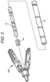
FIG. 1 is a front perspective view of a dispenser in the form of a glass ampoule assembly; -
FIG. 2 is an exploded front perspective view of the glass ampoule assembly shown inFIG. 1 ; -
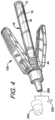
FIG. 3 is an exploded front perspective view of the glass ampoule assembly shown inFIG. 1 and also a dispenser actuator assembly according to an exemplary embodiment of the invention; -
FIG. 4 is a front perspective view of the dispenser actuator assembly mounted on the dispenser in the form of the glass ampoule assembly; -
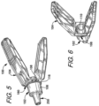
FIG. 5 is a front perspective view of the dispenser actuator assembly according to an exemplary embodiment of the invention; -
FIG. 6 is a rear perspective view of the dispenser actuator assembly shown inFIG. 5 ; -
FIG. 7 is a side elevation view of the dispenser actuator assembly shown inFIG. 5 ; -
FIG. 8 is a top plan view of the dispenser actuator assembly shown inFIG. 5 , a bottom view being general identical; -
FIG. 9 is a front elevation view of the dispenser actuator assembly shown inFIG. 5 ; -
FIG. 10 is a rear elevation view of the dispenser actuator assembly shown inFIG. 5 ; -
FIG. 11 is an enlarged rear perspective view of the dispenser actuator assembly shown inFIG. 5 ; -
FIG. 12 is a cross-sectional view of the dispenser actuator assembly taken along Line 12-12 ofFIG. 12 ; -
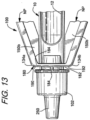
FIG. 13 is a partial side elevation view of the dispenser actuator assembly mounted on the glass ampoule assembly ofFIG. 1 ; -
FIG. 14 is a partial cross-sectional view of the dispenser actuator assembly mounted on the glass ampoule assembly; -
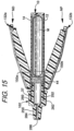
FIG. 15 is a side cross-sectional view of the dispenser actuator assembly mounted on the glass ampoule assembly; -
FIG. 16 is a side cross-sectional view of the dispenser actuator assembly mounted on the dispenser and showing actuation of the dispenser actuator assembly wherein a glass ampoule in the dispenser is fractured; -
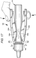
FIG. 17 is a side elevation view of the dispenser actuator assembly mounted on the dispenser and showing actuation of the dispenser; -
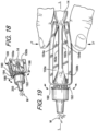
FIG. 18 is a partial front perspective view of the dispenser actuator assembly mounted on the dispenser and showing actuation of the dispenser and further showing flexion of a flex plate of the dispenser actuator assembly; -
FIG. 19 is a side elevation view of the dispenser actuator assembly mounted on the dispenser and showing actuator of the dispenser and further manipulation of the dispenser in dispensing flowable material from the dispenser; -
FIG. 20 is a perspective view of a user engaging the dispenser actuator assembly mounted on the dispenser wherein the dispenser is actuated wherein flowable material is dispensed from the dispenser onto a skin surface; -
FIG. 21 is an exploded front perspective view of a dispenser in the form of a glass ampoule assembly and also another embodiment of the dispenser actuator assembly according to an exemplary embodiment of the invention; -
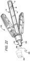
FIG. 22 is a front perspective view of the dispenser actuator assembly ofFIG. 21 mounted on the glass ampoule assembly; -
FIG. 23 is a front perspective view of the dispenser actuator assembly ofFIG. 21 according to another exemplary embodiment of the invention; -
FIG. 24 is a rear perspective view of the dispenser actuator assembly shown inFIG. 21 ; -
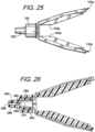
FIG. 25 is a side elevation view of the dispenser actuator assembly shown inFIG. 21 -
FIG. 26 is a cross-sectional view of the dispenser actuator assembly; -
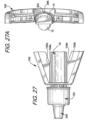
FIG. 27 is a partial side elevation view of the dispenser actuator assembly mounted on the glass ampoule assembly ofFIG. 21 ; -
FIG. 27A is a partial rear perspective view of the dispenser actuator assembly having the glass ampoule assembly mounted thereon and showing a rib engaging the outer container of the glass ampoule assembly; -
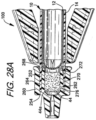
FIG. 28A is a partial side cross-sectional view of the dispenser actuator assembly mounted on the glass ampoule assembly; -
FIG. 28B is a partial side cross-sectional view of the dispenser actuator assembly mounted on the glass ampoule assembly and showing actuation of the glass ampoule assembly; -
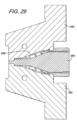
FIG. 29 is a schematic side cross-sectional view of the mold members defining a mold cavity generally corresponding to the dispenser actuator assembly ofFIGS. 5 and23 recognizing mold members for internal structures are not fully shown; -
FIG. 30 is a perspective view of the dispenser actuator assembly mounted on the dispenser in a blister-type package assembly; -
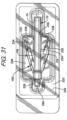
FIG. 31 is a top plan view of the dispenser actuator assembly mounted on the dispenser in a blister package and having wedge members positioned between the actuator arms and dispenser; -
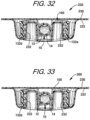
FIG. 32 is a cross-sectional view of the dispenser actuator assembly mounted on the dispenser in a blister package wherein the blister package is formed with integral wedge members positioned between the actuator arms and the dispenser; -
FIG. 33 is a cross-sectional view of the dispenser actuator assembly mounted on the dispenser in a blister package wherein the blister package is formed with alternative integral wedge members positioned between the actuator arms and the dispenser; -
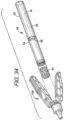
FIG. 34 is an exploded perspective view of the dispenser actuator assembly and an alternative form of the dispenser in the form of a plastic ampoule assembly; -
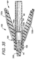
FIG. 35 is a side cross-sectional view of the dispenser actuator assembly mounted on the plastic ampoule assembly of FIG. 46; -
FIG. 36 is a side cross-sectional view of the dispenser actuator assembly mounted on the plastic ampoule assembly of FIG. 46 and showing actuation of the plastic ampoule assembly; -
FIG. 37 is a side elevation view of the dispenser actuator assembly mounted on an alternative embodiment of the dispenser in the form of a tandem glass ampoule assembly; -
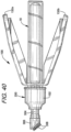
FIG. 38 is a side elevation view of an alternative embodiment of the dispenser actuator assembly according to another exemplary embodiment of the invention; -
FIG. 39 is a side elevation view of another alternative embodiment of the dispenser actuator assembly according to another exemplary embodiment of the invention; -
FIG. 40 is a side elevation view of the dispenser actuator assembly ofFIG. 39 and having an applicator having a silicone tip member; and -
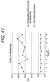
FIG. 41 is a graphical representation of the breakage pressure (force) required to break the glass ampoule assembly via finger pressure (e.g. no actuator assembly) and via use with the dispenser actuator assembly. - While this invention is susceptible of embodiments in many different forms, there are shown in the drawings and will herein be described in detail preferred embodiments of the invention with the understanding that the present disclosure is to be considered as an exemplification of the principles of the invention and is not intended to limit the broad aspect of the invention to the embodiments illustrated.
- The present invention discloses a dispenser actuator assembly that can be used in conjunction with a dispenser to activate the dispenser and dispense flowable material from the dispenser. The dispenser actuator assembly may also be referred to as an ampoule actuator assembly or a dispenser holder or ampoule holder. The dispenser can take various forms and in one particular application, the dispenser may take the form of a glass ampoule assembly. The dispenser in the form of the glass ampoule assembly will be described followed by describing the dispenser actuator assembly including the connection of the components and actuating the dispenser.
-
FIGS. 1-4 disclose a dispenser used in accordance with an exemplary embodiment of the invention and generally designated with thereference numeral 10. Thedispenser 10 generally includes afirst container 12, orinner container 12, and asecond container 14, orouter container 14. A cover member or cap member (not shown but known in the art) may optionally be utilized as explained in greater detail below. In this configuration, thedispenser 10 may also be referred to as aglass ampoule assembly 10. Theglass ampoule assembly 10 generally has an elongated longitudinal axis. It is understood that thedispenser 10 orglass ampoule assembly 10 may take different forms as well such as other devices having rupturable containers. -
FIGS. 1-4 further show thefirst container 12. Thefirst container 12 is generally structured to contain the flowable material M to be dispensed from thedispenser 10. The flowable material M is typically a liquid in an exemplary embodiment. It is understood, however, that flowable materials in other forms could be used such as gels or powders etc. Thefirst container 12 defines achamber 20 therein that contains the flowable material M. Thefirst container 12 has afirst end 22 that is closed and also has asecond end 24 that is closed as well as anintermediate section 26 therebetween. Theintermediate section 26 of thefirst container 12 is generally cylindrical in shape and has a generally circular cross-section. Thefirst end 22 is generally dome-shaped and thesecond end 24 is generally dome-shaped. Other configurations are also possible. As further shown inFIGS. 1-4 , afirst interface area 28 is defined at or proximate the juncture between the first dome-shapedend 22 and an end of theintermediate section 26. Similarly, asecond interface area 30 is defined at or proximate the juncture between the second dome-shapedend 24 and the other end of theintermediate section 26. Thus, thefirst interface area 28 is at the location of thefirst container 12 that transitions from an end of theintermediate section 26 to the dome shape of thefirst end 22. Similarly, thesecond interface area 30 is at the location of thefirst container 12 that transitions from an end of theintermediate section 26 to the dome shape of thesecond end 24. Thefirst container 12 may be dimensioned to have a diameter and length to define thefirst chamber 20 in a size to contain a desired amount of the flowable material M. Thefirst container 12 is designed to be fracturable, frangible, rupturable or crushable as described in greater detail below. In an exemplary embodiment, thefirst container 12 is made from a rigid frangible or crushable material such as glass. Thefirst container 12 may be a traditional glass ampoule. Glass ampoules are known in the art and provide a hermetically-sealed chamber for containing the flowable material M. In one exemplary embodiment, asingle glass ampoule 12 is used. It is understood that thedispenser 10 could be configured to usemultiple glass ampoules 12 as described in greater detail below. -
FIGS. 1-4 further show thesecond container 14, orouter container 14, which can be in the form of an applicator body. Thesecond container 14 has an openfirst end 36 and a closedsecond end 38, and anouter wall 40 therebetween. Adistal end segment 37 of theouter container 14 is defined proximate the openfirst end 36. Theouter wall 40 of thesecond container 14 defines asecond chamber 42. The outer wall further defines anouter surface 56 and aninner surface 58. Thesecond chamber 42 is cooperatively dimensioned and configured to receive at least a portion of thefirst container 12, and typically the entirefirst container 12 is received in thesecond container 14. Thus, in an exemplary embodiment, thesecond container 14 is generally cylindrical and receives thefirst container 12 in a generally snug-fit configuration. Thesecond container 14 is made from a flexible resilient material such as plastic in an exemplary embodiment. Thesecond container 14 may be transparent or translucent plastic wherein the flowable material M in thefirst container 12 can be visible through thesecond container 14 and also through thefirst container 12. Thesecond container 14 may also be made from opaque material when the flowable material M or other contents are light sensitive. - As known in the art, a
glass ampoule assembly 10 may sometimes utilize an applicator assembly positioned in the openfirst end 36 of the outer container. The applicator assembly can take various forms including a swab assembly, a dropper assembly, a roller ball or a brush assembly. The applicator assembly can further be a sponge, foam applicator, fabric, gauze, pen-type applicator or flocked tip. The swab applicator may also take various forms such as being made from absorbent, porous material, and that relies on a wicking action to dispense the flowable material M. The applicator assembly assists in dispensing the flowable material M from thedispenser 10 to a receiving surface. Any applicator assembly that performs this function can be used in thedispenser 10. Theglass ampoule assembly 10 ofFIGS. 1-4 may omit the applicator. It is understood, however, that the glass ampoule assembly may have afilter member 44 operably associated therewith. Thefilter member 44 is structured to allow passage of the flowable material M through thefilter member 44 while preventing passage of glass shards from the fractionatedglass ampoule 12. Thefilter member 44 may be positioned between thefirst end 22 of thefirst container 12 and the open first end of theouter container 14 such as proximate thedistal end segment 37. As explained in greater detail below, it is understood that thefilter member 44 can be relocated from thesecond chamber 42 of theouter container 14 and be operably associated with the dispenser actuator assembly. Thus, thefilter member 44 can be utilized in multiple configurations. - To fabricate the
dispenser 10, thefirst chamber 20 of thefirst container 12 is filled with a desired flowable material M. The open end of thefirst container 12 through which the flowable material passed to fill thefirst container 12 is sealed as is known in glass ampoule technology. A sealedglass ampoule 12 having the flowable material M therein is thereby provided. The filledfirst container 12 is then inserted through the openfirst end 36 and into thesecond chamber 42 of thesecond container 14. Preferably, thefirst container 12 is positioned in its entirety within thesecond chamber 42 of thesecond container 14 orouter container 14. Thefilter member 44, if utilized in this configuration, is inserted into the openfirst end 36 of thesecond container 14 and adjacent the first end of thefirst container 12. In other embodiments, thefilter member 44 may be operably associated with the dispenser actuator assembly. Once thefirst container 12 is positioned in thesecond container 14 as well as thefilter member 44, a cover member could be utilized if desired. Theampoule assembly 10 could also be prepared for mounting to the dispenser actuator assembly as described in greater detail below. - The cover member if utilized is designed to initially cover the open
first end 36 of thesecond container 14 prior to be operably connected to the dispenser actuator assembly. The cover member is dimensioned to fit snugly over thesecond container 14 and extend over a portion of thedispenser 10. A distal end of the cover member is a closed end. When preparing to activate thedispenser 10, the cover member is removed from thedispenser 10. With the present invention as described in further detail below, the cover member is not used during activation of thedispenser 10. It is also understood that thedispenser 10 can incorporate an identifying label. - It is understood that the
dispenser 10 utilizes the cover member 18 in a single-use type container as described above and shown inFIGS. 1-4 . Thedispenser 10 may also eliminate the cover member 18 and be packaged in other outer packaging such as blister packaging. - As shown in
FIGS. 9-18 , the present invention utilizes a dispenser actuator assembly generally designated with thereference numeral 100. Thedispenser actuator assembly 100 may also be referred to as anampoule actuator assembly 100 or dispenser/ampoule holder 100. As explained in greater detail below, thedispenser actuator assembly 100 cooperates with thedispenser 10 to actuate thedispenser 10. The structure of thedispenser actuator assembly 100 will first be described followed by a description of the cooperation and operation of thedispenser actuator assembly 100 with thedispenser 10. - As further shown in
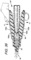
FIGS. 5-20 , thedispenser actuator assembly 100 generally includes abase member 102 and anactuator assembly 104. Theactuator assembly 104 is operably connected to thebase member 102 as further described below. -
FIGS. 5-15 show thebase member 102 of thedispenser actuator assembly 100. Thebase member 102 is generally a rounded member that fits around at least a portion of theglass ampoule assembly 10. Thebase member 102 is further an annular member that in one exemplary embodiment is dimensioned to fit over the dispenser orglass ampoule assembly 10 to achieve a mount between thebase member 102 and theglass ampoule assembly 10 as described in greater detail below. - The
base member 102 generally forms anannular ring member 106 and aconnector member 108. Theannular ring member 106 is a full ring member in an exemplary embodiment that defines anopening 110 therethrough to receive the dispenser as explained in greater detail below. Thus, in an exemplary embodiment, theannular ring member 106 is dimensioned to fit circumjacently around the glass ampoule assembly and, in particular, thesecond container 14. Thebase member 102 further has mounting structures to cooperate with thesecond container 14 as will be described in greater below. It is understood that in other exemplary embodiments, thering member 106 may not be a full ring member and have an interruption, slot or break in the member. Theannular ring member 106 further generally defines theopening 110. Theannular ring member 106 further has aflange 116 extending circumferentially around thering member 106 at a proximate end of thering member 106. Theflange 116 assists in adding rigidity and strength to the proximal end of thebase member 102. The added rigidity and strength provided by theflange 116 also helps when ejector pins push thebase member 102 off of the mold member during the injection molding process. - As discussed and further shown in
FIGS. 5-15 , thebase member 102 in an exemplary embodiment has additional structure for mounting to theampoule assembly 10 as well as anapplicator 250. As explained in greater detail below, thebase member 102 is capable of having theampoule assembly 10 mounted thereto wherein an operable connection is achieved between thebase member 102 and theampoule assembly 10. In addition, in an exemplary embodiment, theapplicator 250 is integrally formed with and on thebase member 102. - As further shown in
FIGS. 6-12 , thebase member 102 has agroove 252 therein that is dimensioned to receive theampoule assembly 10 to mount thebase member 102 on theampoule assembly 10. In particular, thedistal end segment 37 of theouter container 14 of theampoule assembly 10 is inserted into and received by thegroove 252 as will be described in greater detail below. Thegroove 252 in the base member is generally anannular groove 252. Theannular groove 252 has afloor 254 proximate anend segment 256 of thebase member 102, and theannular groove 252 further has a groove end opening 258 that generally corresponds to theopening 110 of thebase member 102. As explained in greater detail below, theannular groove 252 is dimensioned to generally correspond to the size of thesecond container 14, orouter container 14 of theampoule assembly 10, e.g. the general thickness of theouter wall 40 of theouter container 14. It is understood that in an exemplary embodiment, theouter container 14 has a tubular or cylindrical configuration wherein thegroove 252 has an annular cylindrical groove configuration. Other corresponding configurations are also possible to achieve a suitable mount between thebase member 102 and theampoule assembly 10. - As further shown in
FIGS. 6-12 , theannular groove 252 in thebase member 102 defines anouter member 260 and aninner member 262. Thus, theouter member 260 is generally separated from theinner member 262 by thegroove 252. Theouter member 260 defines an outer periphery of thebase member 102 and has aninner surface 264. Theinner surface 264 of theouter member 260 confronts thegroove 252. Theinner surface 264 is generally annular and has a plurality ofribs 266 that extend from theinner surface 264 and into the groove 252 (FIG. 10 andFIG. 27A ). In an exemplary embodiment, theinner surface 264 has a plurality ofribs 266 in the form of fourribs 266. Theribs 266 are spaced along theinner surface 264 and in an exemplary embodiment, may be placed at a 12 o'clock position, a 3 o'clock position, a 6 o'clock position and a 9 o'clock position. Theribs 266 each have a distal end that will engage an outer surface of theouter container 14 of theampoule 10 as will be described in greater detail below. Theinner surface 264 also has a tapered segment at a proximal end of theouter member 260 extending away frominner member 262. It is understood that theribs 266 have a generally longitudinal configuration extending linearly along theouter member 260. In an alternative embodiment, theribs 266 can take the form of circumferential ribs. It is further understood that theouter member 260 and the inner member are circumjacent to one another and generally have concentric configurations around a longitudinal axis of the assembly. - The
inner member 262 has anouter surface 270 that is also generally annular. Theouter surface 270 of theinner member 262 confronts thegroove 252. Theouter surface 270 further has a taperedsegment 272 at a proximal end of theinner member 262. Thetapered segment 272 tapers away from theouter member 260 and towards a central portion of thebase member 102. In one exemplary embodiment, the proximal end of theinner member 262 extends beyond the proximal end of theouter member 260. The length of theinner member 262 can be dimensioned to engage a filter member associated with theampoule assembly 10 or aglass ampoule 12 of theampoule assembly 10 when theampoule assembly 10 is mounted to thebase member 102. Theinner member 262 further defines a centralinternal passageway 274. Theinner member 262 has aninner surface 276 that confronts theinternal passageway 274. Theinner surface 276 is generally annular and further has a generally cylindrical configuration along a majority of its length. Theinner surface 276 further defines additional cut-outs generally at thedistal end segment 256 of thebase member 102. The distal end segment 278 of thebase member 102 has anoutlet aperture 280. Theoutlet aperture 280 is in fluid communication with theinternal passageway 274. As explained in greater detail below, theinternal passageway 274 is dimensioned to receive a filter member in certain exemplary embodiments. -
FIGS. 6-12 further show theapplicator 250. As discussed, in an exemplary embodiment, theapplicator 250 is formed integrally with thebase member 102. Thus, theapplicator 250 extends directly in an integral fashion from thedistal end segment 256 of thebase member 102. Thedistal end segment 256 may have a platform-type configuration wherein theapplicator 250 extends way fromdistal end segment 256. Theapplicator 250 may have a taperedouter surface 282 along the length of theapplicator 250. Theapplicator 250 has aninternal conduit 284 extending through theapplicator 250. Theinternal conduit 284 has adistal end opening 286, anintermediate section 288 and aproximal section 290. Theintermediate section 288 forms generally a central portion of theinternal conduit 284 and has generally a constant inner diameter. It is understood that the inner diameter could take other configurations as desired for dispensing flowable materials. Theproximal section 290 gradually tapers to a smaller diameter towards theoutlet aperture 280 and is in communication with theoutlet aperture 280. Thedistal end opening 286 may have a larger diameter than the diameter of theintermediate section 288 to aid in the desired forming of droplets when dispensing the flowable material as described in greater detail below. - As shown in
FIG. 4 , theapplicator 250 may have tamper resistant features or additional closures. Theapplicator 250 could utilize aremovable member 292 designed to be removably secured on theapplicator 250 over thedistal end opening 286. Theremovable member 292 could take various forms such as a film member or foil member that temporarily covers thedistal end opening 286. The applicator could also have aremovable cap 294 that could be placed back onto theapplicator 250 after an initial amount of flowable material is dispensed. Theremoveable member 292 and theremovable cap 294 are shown in phantom lines inFIG. 4 . -
FIGS. 5-15 further show theconnector member 108 of thebase member 102. Theconnector member 108 generally connects to theactuator assembly 104. Theconnector member 108 extends from a proximate end of theannular ring member 106 towards theactuator assembly 104. Theconnector member 108 has afirst slot 118 orupper slot 118 defined therein as well as asecond slot 120 orlower slot 120 defined therein. As a result, theconnector member 108 has afirst segment 122 and asecond segment 124 defined between thefirst slot 118 and thesecond slot 120. Thefirst segment 122 is positioned generally opposite to thesecond segment 124. Thefirst slot 118 and thesecond slot 120 extend partially circumferentially having respective ends that confront in spaced relation to define thefirst segment 122 and thesecond segment 124. Thefirst slot 118 and thesecond slot 120 are generally opposite to one another. As explained in greater detail below, the slots 118,120 assist in the flexing of theactuator assembly 104, or pivoting movement of theactuator assembly 104. Thefirst segment 122 has a first end connected to thebase member 102 and a second end connected to theactuator assembly 104, or a flex plate of the actuator assembly to be described. Thesecond segment 124 has a first end connected to thebase member 102 and a second end connected to theactuator assembly 104, or a flex plate of the actuator assembly to be described. Thefirst segment 122 has a first raisedtab 126 positioned on a central portion of thefirst segment 122 and that extends from theflange 116 towards the actuator assembly 104 (or to a flex plate as described in greater detail below). Similarly, thesecond segment 124 has a second raisedtab 128 positioned on a central portion of thesecond segment 122 and that extends from theflange 116 to theactuator assembly 104. The raised tabs 126,128 assist in providing rigidity for an enhanced connection between thebase member 102 and theactuator assembly 104. The rigidity provided by the raised tabs 126,128 further help when ejector pins engage thebase member 102 proximate the raised tabs 126,128 to smoothly remove theassembly 100 from a mold member after formation in an injection molding process. - As shown in
FIGS. 5-15 , thebase member 102 is formed as a full annular ring member in one exemplary embodiment. Thebase member 102 is designed to receive or hold thedispenser 10 orglass ampoule assembly 10, and it is understood that thebase member 102 may not have a full ring-shaped configuration. For example, thebase member 102 can have certain segments eliminated and not utilized while still having a configuration to receive or hold theglass ampoule assembly 10. Thebase member 102 could have a slot formed therein to define separate segments that may be resiliently flexible. -
FIGS. 6-12 further show theactuator assembly 104 of thedispenser actuator assembly 100. In one exemplary embodiment, theactuator assembly 104 generally includes afirst actuator arm 132a and asecond actuator arm 132b. As explained in greater detail below, thefirst actuator arm 132a and thesecond actuator arm 132b are connected to thebase member 102 via theconnector member 108 and, in particular, thefirst segment 122 and thesecond segment 124 of theconnector member 108. It is understood that thefirst actuator arm 132a and thesecond actuator arm 132b are similar in structure and positioned generally symmetrically as described in greater detail below. Thefirst actuator arm 132a and thesecond actuator arm 132b extend from the base 102 (or flex plate to be described) in generally opposed relation. It is also understood that description regarding thefirst actuator arm 132a will generally apply to thesecond actuator arm 132b. The structures of thefirst actuator arm 132a are referenced with an "a" designation while the structures of thesecond actuator arm 132b are referenced with a "b" designation. It is also understood that theactuator assembly 104 could utilize a single actuator arm 132. -
FIGS. 5-12 further show thefirst actuator arm 132a. Thefirst actuator arm 132a has aproximal end 134a, adistal end 136a and anintermediate segment 138a. Theproximal end 134a is angled to be generally parallel to theflange 116. Theproximal end 134a is connected to thefirst segment 122 of theconnector member 108 and thesecond segment 124 of theconnector member 108. As shown further inFIG. 8 , theintermediate segment 138a defines afloor segment 140a and an outerperipheral flange 142a. Thefloor segment 140a is recessed with respect to the outerperipheral flange 142a. Theintermediate segment 138a has a plurality ofapertures 144a extending into thefirst actuator arm 132a proximate theproximal end 134a. In an exemplary embodiment, theapertures 144a do not extend entirely through thearm 132a. Theapertures 144a assist in removing certain material in the formation of theassembly 100 to avoid having large block of material associated with theassembly 100 which is generally undesirable in an injection molding process used to form theassembly 100. Theapertures 144a further define additional walls to add further rigidity and strength to theassembly 100. Thefloor segment 140a further has afinger pad 146a in the form of a plurality of raisedridges 148a. The recessed features of the floor and ridges with respect the flange provide for a tactile feel for the user for more proper finger/digit placement, as well as helping to maintain engagement of the fingers/digits with theactuator arms first actuator arm 132a apply to thesecond actuator arm 132b with the "b" designations. - As shown in
FIGS. 5-12 , thefirst actuator arm 132a further has a dependingprotrusion 150a positioned on an underside of thefirst actuator arm 132a. The dependingprotrusion 150a has afirst segment 152a and asecond segment 154a. Thefirst segment 152a defines aplatform 156a proximate to the proximal end of thefirst actuator arm 132a. Thesecond segment 154a extends from thefirst segment 152a at aninterface edge 158a. Theinterface edge 158a may be considered as defining a lined projection to be described in greater detail below. The lined projection is useful in providing a concentrated force against theglass ampoule assembly 10 as described in greater detail below. As further shown inFIG. 11 , thesecond segment 154a has a plurality ofchannels 160a defined therein wherein thesecond segment 154a defines a plurality of spacedwalls 162a. In an exemplary embodiment, thesecond segment 154a has a pair ofchannels 160a that define three spacedwalls 162a. Thewalls 162a add stiffness to theactuator arm 132a. The second segment 154 and thewalls 162a are dimensioned such that they follow the extension of thefirst actuator arm 132a. Thesecond segment 154a inclines upward towards thedistal end 136a of thearm 132a, thus thesecond segment 154a defines an inclined surface. As explained in greater detail below, this configuration allows the second segment 154 to be generally parallel to a longitudinal axis of theglass ampoule assembly 10 when a user manipulates material from theassembly 10 by further squeezing theactuator arm 132a. With thewalls 162a depending from an underside surface of thefloor segment 140a of theactuator arm 132a, theactuator arm 132a is designed similar to an I-beam wherein the structure provides strength, rigidity and stiffness to theactuator arm 132a. The walls 162 depend from an underside surface of theactuator arm 132a. The top of theactuator arm 132a remote from the proximal end remains a solid structure without openings to provide tactile feel while the spacedwalls 162a provide strength etc. to theactuator arm 132a. - As shown in
FIGS. 10 and 11 , aboss 164a is defined at a distal end of thesecond segment 154a of the dependingprotrusion 152a. In an exemplary embodiment, aboss 164a is defined at the distal end of each spacedwall 162a. Theboss 164a is configured to be engaged by ejector pins in ejecting the molded part from a mold during an injection molding process used to form thedispenser actuator assembly 100 as described in greater detail below. As further shown inFIGS. 10 and 11 , anindentation 166a, orindentation slot 166a is defined in theactuator arms 132a adjacent thebosses 164a. Theindentation 166a is generally defined between an underside surface of theactuator arm 132a and theboss 164a. As described in greater detail below, during the injection molding process used to form theassembly 100, fingers defined in the mold part extend into the mold cavity to define theindentations 166a. The fingers will maintain theactuator arms bosses 164a. This minimizes the chance for theactuator arms second segment 154a allows thesecond segment 154a to manipulate theglass ampoule assembly 10 to provide an enhanced pumping action to expel more fully the flowable material M from theglass ampoule assembly 10. As discussed, the above description of the structure of thefirst actuator arm 132a is applicable for the structure of thesecond actuator arm 132b and having "b" designations. - The
dispenser actuator assembly 100 is used with adispenser 10 such as theglass ampoule assembly 10 to crush theglass ampoule assembly 10 and dispense flowable material from theglass ampoule assembly 10. As can be appreciated fromFIG. 8 , theglass ampoule assembly 10 is prepared such as by removing a cardboard sleeve if the sleeve is being used or removing theglass ampoule assembly 10 from any blister packaging. Alternatively, theglass ampoule assembly 10 may use the cover member 18 which is removed in preparation for dispensing flowable material from theglass ampoule assembly 10. - As can be appreciated from
FIGS. 13-15 , theglass ampoule assembly 10 is inserted into thebase member 102 to mount theglass ampoule assembly 10 to thedispenser actuator assembly 100. Thedistal end segment 37 of theouter container 14 is inserted through theopening 110 of thebase member 102. In particular, thedistal end segment 37 passes through thegroove end opening 258 and into theannular groove 252 of thebase member 102. Thedistal end segment 37 bottoms out against thegroove floor 254. Thetapered segment 268 of the inner surface of theouter member 260 and thetapered segment 272 of theinner member 262 assist in guiding theouter container 14 into thegroove 250. In an exemplary embodiment, thegroove 252 and theouter container 14 are cooperatively dimensioned wherein thedistal end segment 37 fits into thegroove 252 in an frictional interference fit. Thus, theouter surface 56 of theouter container 14 may engage theinner surface 264 of theouter member 260 and further, theribs 266 engage theouter surface 56. Theouter surface 270 of theinner member 262 engages theinner surface 58 of theouter container 14. As shown also, for example, inFIG. 27A as well, theribs 266 can engage theouter container 14. It is also understood that theinner surface 264 can be in surface-to-surface engagement with theouter surface 56 of theouter container 14. Also, an end surface of thedistal end segment 37 of theouter container 14 engages thefloor 254 of thegroove 252 in thebase member 102. It is understood that other structural configurations can be achieved to form an interference fit between thebase member 102 and theampoule assembly 10 as well as other types of mounting configurations. - As shown in
FIGS. 13 and14 , a gap may be maintained between the proximal end of theinner member 262 and theglass ampoule 12. In other exemplary embodiments, thefilter member 44 may be positioned between the proximal end of theinner member 262 and theglass ampoule 12 such as shown inFIG. 15 . It is further understood in other embodiments that the length of theinner member 262 can be dimensioned to abut against theglass ampoule 14. In still other exemplary embodiments described below, thefilter member 44 can be positioned in theinternal passageway 274 defined by theinner member 262. Once theampoule assembly 10 is inserted into thegroove 252 and mounted on thebase member 102, theactuator arms ampoule assembly 10. It is understood that thefilter member 44 can be impregnated withother materials 44a if desired such as when it is desired to react or mix with the flowable material M in theampoule assembly 10. - As further shown in
FIGS. 16-20 , when thedispenser actuator assembly 100 is properly mounted to the glass ampoule assembly, the first dependingprotrusion 150a and the second dependingprotrusion 150b are positioned proximate thefirst interface area 28 of theglass ampoule 12. In particular, in one exemplary embodiment, theinterface edge 158a of the first dependingprotrusion 150a and theinterface edge 158b of the second dependingprotrusion 150b are positioned at the first interface area of thefirst container 12 of theglass ampoule assembly 10. In addition, thefirst actuator arm 132a and thesecond actuator arm 132b extend towards theclosed end 38 of thesecond container 14 of theglass ampoule assembly 10. -
FIGS. 13-15 show the dispenser actuator assembly operably connected to theglass ampoule assembly 10. Theglass ampoule assembly 10 is now ready to be actuated. Thefirst container 12, orglass ampoule 12, is in a position to be crushed wherein the flowable material M can be dispensed from theassembly 10. As further shown inFIG. 13 , the first dependingprotrusion 150a of thefirst actuator arm 132a and the second dependingprotrusion 150b of thesecond actuator arm 132b are spaced from thesecond container 14 and positioned over and proximate thefirst interface area 28. Thus, a gap or space is initially maintained between theprotrusions second container 14. In such position as shown inFIG. 13 , theactuator arms - As can be further appreciated from
FIGS. 13-16 , a user holds thedispenser actuator assembly 100 wherein a forefinger wraps around an underside of thebase member 102 and engages thesecond actuator arm 132b. A thumb of the user engages thefirst actuator arm 132a. In particular, a user's forefinger and thumb engage therespective finger pads first actuator arm 132a and thesecond actuator arm 132b. The user squeezes theactuator assembly 100 thereby applying a compressive force F (FIG. 16 ) to thefirst actuator arm 132a and thesecond actuator arm 132b. Thus, theactuator arms protrusion 150a of thefirst actuator arm 132a is deflected towards and engages thesecond container 14 and the dependingprotrusion 150b of thesecond actuator arm 132b is deflected towards and engages thesecond container 14. As the user continues to depress thefirst actuator arm 132a and thesecond actuator arm 132b, the dependingprotrusion 150a of thefirst actuator arm 132a deflects thesecond container 14 wherein thesecond container 14 engages theglass ampoule 12 at proximate a top or upper portion of thefirst interface area 28, and the dependingprotrusion 150b of thesecond actuator arm 132b deflects thesecond container 14 wherein thesecond container 14 engages theglass ampoule 12 at proximate a bottom or lower portion of the first interface area 28 (e.g. opposite ends of the first interface area 28), wherein theglass ampoule 12 is crushed at thefirst interface area 28. In particular, it is understood that thefirst interface area 28 is engaged by theprotrusion interface edge protrusions actuator arms protrusion interface edges outer container 14 andglass ampoule 12. - It is further understood that the
first slot 118 orupper slot 118 and thesecond slot 120 orlower slot 120 assist on providing sufficient flexibility for theactuator arms actuator arms base member 102, theactuator arms base member 102. This allows thebase member 102 to continue to provide support for holding theglass ampoule assembly 10 independently of the pivoting of theactuator arms actuator arms arms arms glass ampoule 12, through the filter member 44 (if used) and into theapplicator 250. Because force F is applied to theglass ampoule 12 at thefirst interface area 28, the domed portion of theglass ampoule 12 breaks into multiple pieces allowing enhanced flow of the flowable material M out of theglass ampoule 12 and into thesecond container 14 and to the applicator assembly 16. It has been determined by the inventors that if theglass ampoule 12 is crushed at theinterface area 28, the domed-section will break into multiple pieces rather than remaining intact while breaking away from the intermediate section of theglass ampoule 12. The flowable material M passes from thesecond container 14 and into the applicator assembly 16.FIG. 18 discloses a partial view of the actuation of theglass ampoule assembly 10 wherein the dependingprotrusions second actuator arms second container 14 of theglass ampoule assembly 10. - As further can be appreciated from
FIG. 19 , the user can continue to squeeze theactuator assembly 100 wherein the user engages thefirst actuator arm 132a and thesecond actuator arm 132b thereby continuing to apply the compressive force F wherein the dependingprotrusions second container 14. As the user continues to depress first andsecond actuator arms second segments protrusions second container 14 wherein thesecond container 14 engages theglass ampoule 12 further along theglass ampoule 12. In this configuration such as shown inFIG. 19 , therespective segments glass ampoule 12 may be sized such that the respectivesecond segments second interface area 30 wherein theglass ampoule 12 further ruptures. Upon this additional rupture, the flowable material M more easily passes from theglass ampoule 12 and into thesecond container 14 and into the applicator 16. Because force F is applied to theglass ampoule 12 at thesecond interface area 30, the domed portion of theglass ampoule 12 breaks into multiple pieces allowing enhanced flow of the flowable material M out of theglass ampoule 12 and into thesecond container 14 and to the applicator assembly 16. It is further understood that the user can use theactuator arms second segments second container 14 and force the flowable material M through the applicator assembly 16 and, therefore, to enhance dispensing of the flowable material M from theglass ampoule assembly 10. - It is understood that the
filter member 44 assists in minimizing the chance of glass shards from the rupturedglass ampoule 12 from passing out of theglass ampoule assembly 10. In addition, the outer wall of thesecond container 14 prevents glass shards from cutting fingers of the user thereby protecting the user's fingers from injury by the fractionated glass shards of theglass ampoule 12 that remain in thesecond container 14. Because a user engages theactuator assembly 100 to crush theglass ampoule assembly 10 rather than engaging theglass ampoule assembly 10 directly, the chance of cutting a user's fingers/thumb from glass shards is further minimized. It is understood that additional structures could be incorporated into theglass ampoule assembly 10 such asmultiple filter assemblies 44 to minimize the chance of glass shards from passing through the applicator assembly. As shown inFIG. 20 , the flowable material M can be dispensed from theglass ampoule assembly 10 and onto a receiving surface S. The receiving surface S can vary depending the particular type of flowable material M being dispensed. In one exemplary embodiment, the flowable material M may be a medicine that is dispensed onto a skin surface S of a patient. - As further appreciated from the figures, the user dispenses the flowable material M from the
glass ampoule assembly 10 with the aid of thedispenser actuator assembly 10. Once the flowable material M is emptied from theglass ampoule assembly 10, thedispenser actuator assembly 100 can be removed from theglass ampoule assembly 10. In this fashion, thedispenser actuator assembly 10 can be reused withmultiple dispenser assemblies 10 orglass ampoule assemblies 10 if desired and the flowable material M is a type allowing for such re-use. In this configuration, thedispenser actuator assembly 100 can be formed from a more robust and higher-cost material. In other configurations, the material used to form thedispenser actuator assembly 100 could be a lower cost material that is designed as a one-time use wherein thedispenser actuator assembly 100 is disposable and/or where the flowable material M is such that thedispenser actuator assembly 100 andampoule assembly 10 should be discarded after a single use. Thus, once the flowable material M is fully dispensed from theglass ampoule assembly 10, the attached structures can be simply discarded together. - It is understood that the
dispenser actuator assembly 100 can be formed in an injection molding process to form a unitary one-piece member. A wide variety of materials can be used to form thedispenser actuator assembly 100 wherein theactuator arms actuator arms base member 102. Similarly, the dependingprotrusions - As discussed herein, the
dispenser actuator assembly 100 has been described herein as having abase member 102 and anactuator assembly 104 having afirst actuator arm 132a and asecond actuator arm 132b. Aconnector member 108 has been described that connects thebase member 102 and theactuator assembly 104. It is understood that theactuator arms base member 102 andconnector member 108. It is understood that theassembly 100 could also be considered that thefirst actuator arm 132a and thesecond actuator arm 132b are connected by acentral hub member 180 orflex plate 180, ortorsion plate 180. In particular, aproximal end 134a of thefirst actuator arm 132a is connected to a top portion or first end of theflex plate 180, and aproximal end 134b of thesecond actuator arm 132b is connected to a bottom portion or second end of theflex plate 180. The first end of theflex plate 180 is generally opposite to the second end of theflex plate 180. In one exemplary embodiment, theflex plate 180 is then considered to be part of theactuator assembly 104. Theflex plate 180 is generally connected between theactuator arms flex plate 180 is connected to theproximal end 134a of thefirst actuator arm 132a, and an opposite second end, or lower end of theflex plate 180 is connected to theproximal end 134b of thesecond actuator arm 132b. In this configuration, thebase member 102 is still operably connected to theactuator assembly 104 by theconnector member 108. Theflex plate 180 serves as a transition structure from thebase member 102 to theactuator arms - The
flex plate 180 can be further understood with reference toFIGS. 13 and18 . Theflex plate 180 has acentral portion 182 and afirst side rail 184 and asecond side rail 186, generally opposite thefirst side rail 184. Thecentral portion 182 of theflex plate 180 has anopening 188 therethrough. The flex plate opening 188 (FIG. 14 ) is generally aligned with theopening 110 of thebase member 102 as further described below. Theflex plate opening 188 may be slightly larger than theopening 110 of thebase member 102 or the same size. Thus, theflex plate opening 188 has a diameter larger than a diameter of the opening of thebase member 102. Thecentral portion 182 further has afirst flexion segment 190 orupper flexion section 190, and asecond flexion segment 192 orlower flexion segment 192 as further described below. An upper portion of thefirst flexion segment 190 is adjacent theproximal end 134a of thefirst actuator arm 132a at afirst connection line 194, generally at the first end of theflex plate 180. A bottom portion of thesecond flexion segment 192 is adjacent theproximal end 134b of thesecond actuator arm 132b at asecond connection line 196, generally at the second end of theflex plate 180. As further shown inFIGS. 13 and18 , thecentral portion 182 of theflex plate 180, including thefirst flexion segment 190 and thesecond flexion segment 192, have a lesser thickness than the thickness of thefirst side rail 184 and thesecond side rail 186. It is understood that thefirst flexion segment 190 is positioned generally between a midpoint of the vertical length of theflex plate 180 and the location where thefirst actuator arm 132a is connected to theflex plate 180. Similarly, thesecond flexion segment 192 is positioned generally between a midpoint of the vertical length of theflex plate 180 and the location where thesecond actuator arm 132b is connected to theflex plate 180. Theflex plate 180 generally flexes or bends at positions between where theconnector member 108 connects to the flex plate (thefirst segment 122 and the second segment 124) and where theactuator arms flex plate 180. As discussed, thefirst slot 118 is defined between the first end of theflex plate 180 and thebase 102. Thesecond slot 120 is defined between the second end of theflex plate 180 and thebase 102. - As can be further appreciated from
FIG. 18 , theflex plate 180 is connected to thefirst actuator arm 132a and thesecond actuator arm 132b. In this exemplary embodiment of the invention, theflex plate 180 and thefirst actuator arm 132a and thesecond actuator arm 132b define theactuator assembly 104. The upper portion of thefirst flexion segment 190 and upper portions of the first and second side rails 184,186 are connected to theproximal end 134a of thefirst actuator arm 132a at thefirst connection line 194. Similarly, the lower portion of thesecond flexion segment 192 and lower portions of the first and second side rails 184,186 are connected to theproximal end 134b of thesecond actuator arm 132b. Thefirst segment 122 of theconnector member 108 is connected to the central portion of theflex plate 180 and also to thebase 102. Thus, thefirst segment 122 has a first end connected to thebase 102 and a second end connected to theflex plate 180. The first raisedtab 126 is connected to thefirst side rail 184 and also connected to theflange 116 of thebase 102. Thesecond segment 124 of theconnector member 108 is connected to the central portion of theflex plate 180 and also to thebase 102. Thus, thesecond segment 124 has a first end connected to thebase 102 and a second end connected to theflex plate 180. The second raisedtab 128 is connected to thesecond side rail 186 and also to theflange 116 of thebase 102. With these connections, theflex plate opening 188 is generally aligned with theopening 110 of thebase member 102. Accordingly, theconnector member 108 operably connects thebase member 102 to theactuator assembly 104. As discussed, the segments 122,124 of theconnector member 108 are connected to theflex plate 180. It is further understood that theflex plate 180 could have location structures thereon to properly position thedispenser actuator assembly 100 on theglass ampoule assembly 10. It can further be appreciated that theflex plate 180 is dimensioned to extend beyond the outer periphery of thebase member 102. - As previously discussed and as shown in
FIGS. 13-16 , thedispenser actuator assembly 100 is mounted to theglass ampoule assembly 10 and in a position wherein the protrusions 150,152 can crush theglass ampoule 12. This configuration may be considered the first position or neutral position NP. In this configuration, theflex plate 180 is unflexed and is generally in a planar configuration such as shown inFIGS. 13-15 . Similar to the description above, a user engages thefirst actuator arm 132a and thesecond actuator arm 132b and applies a force F wherein thearms arms flex plate 180 flexes generally at thefirst flexion segment 190 and thesecond flexion segment 192. This flexion of theflex plate 180 is shown inFIGS. 16-19 . Thefirst flexion segment 190 and thesecond flexion segment 192 provides for flexion over a greater radius, which lessens the stress on theassembly 100. If theactuator arms first connection line 194 and thesecond connection line 196, stresses are more locally focused at a smaller area, which is undesirable as it can promote plastic deformation of the material. Thefirst flexion segment 190 and thesecond flexion segment 192 provide elastic deformation of theflex plate 180, which allows theflex plate 180 to return to its first or neutral position NP. Thus, theflex plate 180 is resiliently deflectable.FIGS. 17-19 shows the flexion of thefirst flexion segment 190 and thesecond flexion segment 192 represented by the angular configuration "A" and which further provides for the majority of the flexing of theflex plate 180. Additional arrows A inFIGS. 17-19 further show the flexion of theflex plate 180. It is understood that theactuator arms first connection line 194 and thesecond connection line 196. The flexion is concentrated at theflex plate 180 as shown. - As further shown in
FIG. 19 , a user can continue to press theactuator arms glass ampoule assembly 100 wherein thesecond segments actuator arms outer container 14 of theglass ampoule assembly 10. Furthermore, thewalls outer container 14 and further manipulate theglass ampoule 12 wherein thewalls glass ampoule assembly 100. - The
base member 102 utilizing the slots 118,120 or theflex plate 180 and slots 118,120 provides structural and functional advantageous features. As discussed, theactuator arms flex plate 180 flexes as shown inFIGS. 17-19 and such flexing occurs over a greater distance, e.g., a more substantial distance associated with theflex plate 180. In particular, much of the bending or flexing occurs at thefirst flexion segment 190 and thesecond flexion segment 192. This distributes stresses associated with the flexing over a greater distance on theflex plate 180 as opposed to a flexing configuration at a point such as a living hinge. With flexing and distributed stresses over a greater distance, any breaking point is minimized wherein the material of theassembly 100 is not pushed past its elastic limits. This allows theactuator arms assembly 100 can be used with furtherglass ampoule assemblies 10. If the flexing structure was a living hinge structure, force would be focused at a more localized point, which would promote a failure or breaking of theactuator arm base member 102. This configuration further provides for substantiallyrigid actuator arms arms actuator arms flex plate 180 flexes to allow the substantiallyrigid actuator arms protrusions glass ampoule assembly 10. This configuration also provides for flexing/movement of theactuator arms outer container 14 by thebase member 102. Thebase member 102 supports theouter container 14 of theglass ampoule assembly 10 as theouter container 14 is inserted through thebase member 102. With the slots 118,120 and theflex plate 180, theactuator arms flex plate 180, which is independent of the support thebase member 102 provides to theouter container 14. In other designs where wings or arms project directly from or an integral connection to a base, the base member can distort or deform in response to the movement of thearms ampoule assembly 10 can be lessened, altered or otherwise adversely affected. With the present design, the support of theglass ampoule assembly 10 by thebase member 102 is isolated from theactuator arms actuator arms - Finally, the structural features of the
flex plate 180 andactuator arms actuator arms actuator arms flex plate 180, e.g., the first and second connection lines 194,196, which connection generally resists lateral movement of theactuator arms actuator arms glass ampoule 12 as theprotrusion glass ampoule 12 preventing crushing. As shown inFIG. 13 , thebase member 12 supports theglass ampoule assembly 10 across a lateral distance "a" that may generally correspond to a diameter of theglass ampoule assembly 10, e.g. a diameter dimension. Theactuator arms flex plate 180 extends beyond the diameter of theglass ampoule assembly 10. With a greater dimension "b", theactuator arms FIG. 33 ) of theglass ampoule assembly 10. These structural and functional features of thedispenser actuator assembly 100 provide benefits over prior assemblies. -
FIGS. 21-28B disclose anotherdispenser actuator assembly 100 according to another exemplary embodiment of the invention. The structure and function of the dispenser actuator assembly ofFIGS. 21-28B are similar to the embodiment ofFIGS. 1-20 and like structures are referenced with identical reference numerals. The above description generally applies to this embodiment. Additional differences will be further described below. - As shown, for example, in
FIG. 26 , theinner member 262 of thebase member 102 is shorter in length than the previous embodiment. A proximal end of theinner member 262 of thebase member 102 is generally aligned with a proximal end of theouter member 260 of thebase member 102. Theouter member 260 andinner member 262 have similar tapered surfaces and are separated to define thegroove 252 in thebase member 102. In such configuration, theglass ampoule 12 can be positioned generally at the proximal end of theinner member 262. - As shown in
FIG. 28 , theinner member 262 defines theinternal passageway 274. In this embodiment, thefilter member 44 is positioned in theinternal passageway 274 in an interference fit rather than being positioned in theouter container 14 of theglass ampoule assembly 10. - As shown in
FIG. 28A , theglass ampoule assembly 10 is mounted to thedispenser actuator assembly 100. As with the previous embodiment, thedistal end segment 37 of theouter container 14 of theglass ampoule assembly 10 is inserted into thegroove 252 of thebase member 102. Thus, theglass ampoule assembly 10 is mounted to thebase member 102. Thedispenser actuator assembly 100 and glass ampoule assembly are operably connected and mounted to one another in the same manner as described above. As discussed, an frictional interference fit can be achieved between thebase member 102 and theouter container 14. As shown inFIG. 27A , therib 266 engages theouter container 14 when theouter container 14 is inserted into to thegroove 252. As shown inFIG. 28B ., a user actuates thedispenser actuator assembly 100 by applying force to theactuator arms glass ampoule 12, through thefilter member 44, and theapplicator 250. - As discussed, in an exemplary embodiment, the
dispenser actuator assembly 100 is formed as a single unit in an injection molding process.FIG. 29 shows a schematic view of multiple mold members used to injection mold thedispenser actuator assembly 100. It is understood that the process in disclosed in greater detail inU.S. Patent Application No. 16/598,913 . It is further understood that an internal mold member is shown schematically and does not fully show structures to form certain structures such as theinner member 262. -
FIG. 29 discloses acore mold member 200 used in making thedispenser actuator assembly 100, and anupper mold member 202 and alower mold member 204. Thecore mold member 200, theupper mold member 202 and thelower mold member 204 are positioned in adjacent spaced relation to cooperate to define and form amold cavity 206 to receive the injected molded material. It is understood that additional mold members can be used as well as other structures and mechanisms such as gates known in the art of injection molding. The multiple mold members cooperate to form a mold cavity wherein material in injected into the mold cavity to form thedispenser actuator assembly 100 as can be appreciated from the figures. - The
dispenser actuator assembly 100 can be formed in the injection molding process from a variety of different injected molded materials. Selection of the material will depend on the desired operational characteristics of theassembly 100 such as the amount of rupturing force to be generated. Theassembly 100 could be formed from polyolefin family of resins. The material could be polyethylene or polypropylene and a combination thereof. The material could also be nylon. Because of the structural features described above, it is possible to use more rigid/brittle materials as well as materials having a higher flexural modulus. The material could also be amorphous polymers including acrylic, acrylonitrile butadiene styrene, or polycarbonate. The material for theassembly 100 could further be a polyvinylidene fluoride (PVDF) material. With the broader selection of materials possible, theassembly 100 can also be used in a broader range of applications requiring rupturing of different types of containers. Thedispenser actuator assembly 100 could also be made of materials for specialty application such as materials that are capable of being autoclavable. - It is understood that the
dispenser actuator assembly 100 can have certain modified structures to enhance the operability of theassembly 100. Theassembly 100 may have dispenser actuator assemblies of 100 of different sizes. Theassemblies 100 may further have different thumb pad designs or configurations. - Prior to the invention, a user typically must squeeze, via finger pressure, the
outer container 14 of theglass ampoule assembly 10 to crush theglass ampoule 12. The squeezing thumb/fingers provides a force to deform theouter container 14 and crush theglass ampoule 12. The required finger pressure could be considered significant for certain users having limited strength in their respective digits. Thedispenser actuator assembly 100 provides mechanical advantage from theactuator arms FIG. 41 shows graphically, the reduction in finger pressure required to crush the glass ampoule. The upper line represents the finger pressure required to crush theglass ampoule assembly 10 when a user directly squeezes, via finger pressure, theouter container 14 of theglass ampoule assembly 10. The required pressure is typically approximately 15-20 psi. The lower line represents the finger pressure required to crush theglass ampoule assembly 10 when thedispenser actuator assembly 100 is used. As can be seen, the finger pressure required is typically less than 5 psi and could be approximately 3-4 psi. A significant reduction in required psi is achieved with thedispenser actuator assembly 100. A lower, more constant and predictable breakage force is also achieved. It is understood that thedispenser actuator assembly 100 could include alternative features to provide further reduction is required psi as desired. It is understood that the angle that theactuator arms base member 102 orflex plate 180 can vary and set at a greater angle that would allow more force to be generated. This can lead to a more difficult grip for certain users and, therefore, a sufficient angle is determined to provide the necessary rupturing force with an ergonomically-friendly grip of a user. - It is understood that the
dispenser actuator assembly 100 and theglass ampoule assembly 10 may be distributed or sold as a kit, e.g., together as a single unit package.FIG. 30 shows arepresentative package assembly 220, which may be ablister package 220. Theblister package 220 containing thedispenser 10 andactuator assembly 100 may be referred to as a dispenser and actuator assembly package assembly. Thedispenser actuator assembly 100 is mounted on theglass ampoule assembly 10 generally proximate a central intermediate segment of theouter container 14 of theglass ampoule assembly 10 to form a tandem unit. Thepackage assembly 220 is provided having abottom member 222 orblister layer 222. Theblister layer 222 has ablister recess 224 dimensioned to receive the tandem unit. Therecess 224 has afirst recess section 226 and asecond recess section 228. Thefirst recess section 226 has a greater longitudinal dimension than a lateral dimension to receive and accommodate theglass ampoule assembly 10. Thesecond recess section 228 is generally rectangular and intersects thefirst recess section 226 at generally a central portion of thefirst recess section 226. Thesecond recess section 228 defines anouter wall 229. Thesecond recess section 228 is generally dimensioned to receive thedispenser actuator assembly 100 mounted on theglass ampoule assembly 10. When the tandem unit is placed in therecess 224, package spaces PS are defined between theactuator arms glass ampoule assembly 10. Thebottom member 222 can be formed from materials that resist inadvertent forces being placed onto the actuator arms of the dispenser actuator assembly inside the package. Theblister layer 222 can be made from a variety of different materials. In one exemplary embodiment, theblister layer 222 is made of a thermoplastic material, such as polyvinyl chloride or polyolefin. Still other materials are possible and theblister layer 222 can also be laminated with other layers such as a tear resistant layer. - As discussed, the
package assembly 220 may be considered a blister package wherein acover member 230 orfilm member 230 is adhered over theblister layer 222 to seal the tandem unit in thepackage assembly 200 until ready to be used. Thecover member 230 can also be made from a variety of materials including a paper material, a thermoplastic film layer or a foil layer or still other materials. The foil member could be an aluminum foil. Thecover member 230 could also be formed from a laminate material of a paper and a metal foil layer. The foil layer could also be coated with a film of a thermoplastic material such as polyethylene, polystyrene or the like. Thecover member 230 is secured to theblister layer 222 by sealing through the application of heat and pressure. Other sealing techniques between thecover member 230 and theblister layer 222 can also be utilized. In one exemplary embodiment, thecover member 230 is releasably secured or releasably sealed to theblister layer 222. Thecover member 230 may define a pull tab for a user to pull thecover member 230 from theblister layer 222. In other exemplary embodiments, thecover member 230 can be punctured or torn to gain access to the dispenser and actuator assembly tandem unit. The tandem unit in thepackage assembly 220 can then be further packaged, boxed, shipped or otherwise transported in preparation for use. -
FIGS. 31-33 show additional features associated with thepackage assembly 220.FIG. 31 shows thepackage assembly 220 containing the tandem unit of thedispenser actuator assembly 100 mounted on theglass ampoule assembly 10. The tandem unit is positioned in theblister recess 224. As further shown inFIG. 31 ,wedge members 232, or first and second blockingmembers 232, can be utilized between theglass ampoule assembly 10 and theactuator arms dispenser actuator assembly 100. The blockingmember 232, orwedge member 232, generally has a right-triangle-type shape having anangled surface 234 and a primarylinear surface 236, as well as a secondarylinear surface 238. A right angle is defined between the linear surfaces 236,238. In this exemplary embodiment, twowedge members 232 are utilized, e.g. afirst blocking member 232 and asecond blocking member 232. As further shown in FIG. 43A, afirst blocking member 232 is positioned in the package space PS or recess space PS in thesecond recess section 228 generally between thefirst actuator arm 132a and thesecond container 14 of theglass ampoule assembly 10. In particular, the firstangled surface 234 of thefirst blocking member 232 is positioned in confronting relation to thesecond segment 154a of the dependingprotrusion 150a. Thesecond segment 154a of the first depending protrusion 150 defines an inclined surface as shown inFIG. 31 . In an exemplary embodiment, the respective surfaces of theangled surface 234 of the blockingmember 232 and depending protrusion 150 engage one another. It is understood that a small gap could be present if desired. The primarylinear surface 236 engages the outer surface of thesecond container 14 of theglass ampoule assembly 10, e.g. the straight cylindrical surface of thesecond container 14. The secondarylinear surface 238 engages a rear wall portion of thesecond recess section 228. Thus, thefirst blocking member 232 is confined or wedged between thefirst actuator arm 132a and thesecond container 14 of theglass ampoule assembly 10. - Similarly, a
second blocking member 232 is positioned in the package space PS or recess space PS in thesecond recess section 228 generally between thesecond actuator arm 132b and thesecond container 14 of the glass ampoule assembly 10 (e.g., generally opposed to the first blocking member 232). In particular, the secondangled surface 234 of thesecond blocking member 232 is positioned in confronting relation to thesecond segment 154b of the dependingprotrusion 150b, that defines a second inclined surface of thesecond actuator arm 132b. In an exemplary embodiment, the respective surfaces of the secondangled surface 234 and depending protrusion 150 engage one another. It is understood that a small gap could be present if desired. The primarylinear surface 236 of thesecond blocking member 232 engages the outer surface of thesecond container 14 of theglass ampoule assembly 10, e.g. the straight cylindrical surface of thesecond container 14. The secondarylinear surface 238 engages a rear wall portion of thesecond recess section 228. Thus, thesecond wedge member 232 is confined or wedged between thesecond actuator arm 132b and thesecond container 14 of theglass ampoule assembly 10. As further shown inFIG. 31 , the respectivedistal ends second actuator arms outer walls 229 of thesecond recess section 228 of theblister recess 224. - As can be appreciated from
FIG. 31 , in this configuration, thefirst blocking member 232 and thesecond blocking member 232 prevent movement of theactuator arms glass ampoule 12 of theglass ampoule assembly 10. Even if a small gap is provided between theactuator arms angled surfaces 234 of the blocking members, the gap is controlled such that theactuator arms glass ampoule 12. Thus, in this configuration, thepackage assembly 220 can be further packaged, shipped and transported wherein any jostling of the package will not allow for inadvertent or premature actuation of theglass ampoule assembly 10. -
FIG. 32 shows an alternative embodiment of thepackage assembly 220. In this embodiment, thefirst blocking member 232 and thesecond blocking member 232 are integrally formed in theblister layer 222 of thepackage assembly 220. In an exemplary embodiment, the blockingmembers 232 can be pressed to be integrally formed such as in the shape of the blockingmember 232 shown inFIG. 31 . Other processes can be used to form theintegral blocking members 232 such as blow molding or the like. Thus, theintegral blocking member 232 formed in theblister layer 222 can have the angledsurface 234, primarylinear surface 236 and the secondlinear surface 238. Theintegral blocking members 232 are positioned between theactuator arms glass ampoule assembly 10 as described above. As can be appreciated fromFIG. 32 , in this configuration, the blockingmembers 232 prevent movement of theactuator arms glass ampoule 12 of theglass ampoule assembly 10. Thus, in this configuration, thepackage assembly 220 can be further packaged, shipped and transported wherein any jostling of the package will not allow for inadvertent or premature actuator of theglass ampoule assembly 10. It is appreciated that theintegral blocking members 232 inFIG. 32 would look the same as inFIG. 31 . -
FIG. 33 shows a further alternative embodiment of thepackage assembly 200. Theblister layer 222 further hasintegral blocking members 232 formed therein. In this configuration, the blockingmembers 232 are generally round or circular members, e.g. having a circular cross-section. Similar to the other embodiments, the blockingmembers 232 are formed and dimensioned to be positioned between theactuator arms second container 14 of theglass ampoule assembly 10. As can be appreciated from FIG. 43C, in this configuration, the blockingmembers 232 prevent movement of theactuator arms glass ampoule 12 of theglass ampoule assembly 10. Thus, in this configuration, thepackage assembly 220 can be further packaged, shipped and transported wherein any jostling of the package will not allow for inadvertent or premature actuator of theglass ampoule assembly 10. - The kit described above may include the
dispenser 10, thedispenser actuator assembly 100 and thepackage assembly 220 including any desired blockingmembers 232. It is understood that the kit could include different combinations of such elements or additional elements. For example, the kit could contain multiple applicator assemblies 16 to be used for dispensing flowable materials in different applications. The applicator assembly 16 may also be provided having different tips 54 for different applications. - As discussed above, the
dispenser actuator assembly 100 can be utilized to actuate a glass ampoule assembly such as shown inFIGS. 1-4 . Thedispenser actuator assembly 100 can also be used with other types of glass ampoule assemblies known in the art. Various glass ampoule assemblies can be actuated similar as described above. A user engages thefirst actuator arm 132a and thesecond actuator arm 132b and applies a force F wherein thearms second container 14 is deformed and theglass ampoule 12 is crushed. Flowable material M is then dispensed from theglass ampoule assembly 10 as described above. - As described above, the
dispenser actuator assembly 100 can be used with adispenser 10 such as aglass ampoule assembly 10. It is understood that thedispenser actuator assembly 100 can also be used with other types ofdispensers 10 that utilize a rupturable feature in order to dispense flowable materials M from thedispenser 10.FIGS. 34-36 show anotherdispenser 10 in the form of aplastic ampoule assembly 60. The plastic ampoule assembly has anouter wall 62 and afracturable membrane 64 defining a chamber 66 for containing a flowable material M. Themembrane 64 has aweld seam 68 formed during an injection molding process wherein a first segment of injected molding material abuts a second segment of injected molding material to form theweld seam 68 such as disclosed inU.S. Patent No. 6,641,319 . Themembrane 64 having theweld seam 68 could also be formed in a conical shape such as disclosed inU.S. Patent No. 10,392,163 plastic ampoule 60 can also utilize afilter member 44 for dispensing the flowable material M.FIG. 35 discloses thedispenser actuator assembly 100 mounted to theplastic ampoule assembly 60. The mounting structures and method are similar as described above. Thedispenser actuator assembly 100 andactuator arms interface areas fracturable membrane 64. Similar to the operation described above, after thedispenser actuator assembly 100 is mounted on theplastic ampoule 60, a user applies a compressive force F to theactuator arms protrusions interface areas outer wall 62 of theplastic ampoule 60 thereby applying the force proximate themembrane 64 wherein theweld seam 68 is fractured as shown inFIG. 36 . Thus, theactuator arms weld seam 68, the flowable material M can pass through themembrane 64 and into the applicator 16 to be dispensed from theplastic ampoule 60. It is understood that theprotrusions membrane 64 to apply the force F to themembrane 64 to fracture theweld seam 68. -
FIG. 37 discloses use of thedispenser actuator assembly 100 in use with another alternative embodiment of aglass ampoule assembly 10. The structure of theglass ampoule assembly 10 is generally similar in structure to theglass ampoule assembly 100 ofFIGS. 1-4 . Theglass ampoule assembly 10 inFIG. 37 utilizesmultiple glass ampoules 12 in a tandem unit for a two-part flowable material configuration. Thus, thesecond container 14 contains arear glass ampoule 12 and afront glass ampoule 12. Therear glass ampoule 12 contains a first flowable material M1. Thefront glass ampoule 12 contains a second flowable material M2.FIG. 37 shows thedispenser actuator assembly 100 mounted to theglass ampoule assembly 10. It is understood that theglass ampoule assembly 10 is mounted to thedispenser actuator assembly 100 ofFIG. 37 in the same manner as described above as the mounting structures are the same. Theactuator arms actuator arms rear ampoule 12. It is understood that the protrusion segments crush therespective glass ampoules 12. After crushing therear glass ampoule 12 and thefront glass ampoule 12, the respective flowable materials M1,M2 of theampoules 12 can mix together to form a mixture MX. The user may shake theglass ampoule assembly 10 to assist in the mixing to form the mixture MX. The user can dispense the mixture MX from theapplicator 250 of theglass ampoule assembly 10 onto a receiving surface as described above. -
FIG. 38 disclose an alternative embodiment of the dispenser actuator assembly according to another exemplary embodiment of the invention. In this embodiment, aflex plate 180 is not utilized wherein the actuator assembly is more directly connected to the base member. A cut-out portion to define ahinge 302 is formed at an interface area between thebase member 102 and theactuator arm base member 102 further utilizes theintegral applicator 250 as well as the internal structures for mounting to the glass ampoule assembly as described above. It is understood that theglass ampoule assembly 10 is mounted to thedispenser actuator assembly 100 ofFIG. 38 in the same manner as described above as the mounting structures are the same. -
FIGS. 39-40 disclose an alternative embodiment of thedispenser actuator assembly 100 according to another exemplary embodiment of the invention. In this embodiment, thebase member 102 again utilizes theintegral applicator 250. The applicator utilizes arigid stem 304 defining an internal conduit and having the distal end opening. Therigid stem 304 defining the internal conduit is surrounded by a more flexible silicone applicator tip 306 (FIG. 40 ) having a distal opening in fluid communication with the internal conduit. Thesilicone applicator tip 306 further hasflexible bristles 308 to assist in dispensing the flowable material. It is understood that theapplicator 250 further defines awell member 310 in thebase member 102. Theapplicator tip 306 fills in thewell member 310. It is understood that theglass ampoule assembly 10 is mounted to thedispenser actuator assembly 100 ofFIGS. 39-40 in the same manner as described above as the mounting structures are the same. - The
dispenser actuator assembly 100 provides several benefits. The actuator assembly provides mechanical advantage for a user to crush, rupture or fracture the dispenser. The actuator arms can vary in length and resiliency to provide a desired mechanical force in rupturing the dispenser. Because the dispenser actuator assembly allows for a user to apply an increased force than from finger pressure alone, the assembly can be used to rupture more robustly designed dispensers. Such dispensers may be designed to crush under an increased force to minimize the chances of inadvertent rupture. In addition, the dispenser actuator assembly is designed to crush the glass ampoule at the optimal location at the interface area proximate the domed-portion of the glass ampoule to enhance the rupturing of the glass ampoule. Furthermore, as the user engages the actuator arms of the assembly rather than directly engaging the outer container of the dispenser, the chances that glass shards from the crushed glass ampoule can injure the fingers or hand of the user is minimized. The dispenser actuator assembly can also be adjustably mounted along a length of the glass ampoule assembly. For example, the dispenser actuator assembly can be slid along a length of the outer container of the glass ampoule assembly to a desired location. This helps in further manipulating flowable material from the glass ampoule assembly. In addition, thedispenser actuator assembly 100 can be removable attached to the dispenser. Once the dispenser is crushed and the flowable material is dispensed from the dispenser, the dispenser actuator assembly can be removed from the dispenser and used to crush multiple other dispensers. It is understood as well that thedispenser actuator assembly 100 could be manufactured as a single-use assembly that is discarded. It is further understood that theassembly 100 can be positionally adjusted on theglass ampoule assembly 10 to manipulate flowable material as desired or break the glass ampoule at a particular location. It is further understood that the flex plate structure provides several benefits as discussed above including flexing across a greater distance on the plate as well as providing for movement of the actuator arms independently of the support of the glass ampoule assembly by the base member. The integral applicator provides additional benefits. The structure of the applicator can be controlled in the injection molding process for consistent operation. With the internal mounting structures, the components can be dimensioned to be automatically aligned for optimum actuation. For example, the protrusion can be automatically aligned with the interface area of the glass ampoule for enhanced crushing of the ampoule. The integral applicator further creates efficiencies in manufacture. The distal end opening configuration also provided consistent droplets of the same size for dispensing the flowable material. - It is understood that any reference to an element using designations such as "first" or "second" or the like does not limit the quantity or order of those elements, unless such limitation is explicitly stated. These designations are used to distinguish between elements or other references to an element. Accordingly, a reference to a first element or a second element does not mean that only two elements may be employed or that the first element must precede the second element in some manner. In addition, a set of elements may comprise one or more elements. In addition, references to "top" or "bottom" or "front" or "rear" are used to reference relative positions of elements and should be construed as a limiting positional requirement.
- It is further understood that the present description includes several different embodiments with different features depending on the embodiment being described. It is understood that the various features or structures can be combined among the various embodiments in further exemplary embodiments of the invention.
- The dispenser is permitted to be used in a wide variety of uses and applications, and contain and dispense a large variety of fluids and other flowable substances. The following is a non-exhaustive discussion regarding the many possible uses for the dispenser of the present invention, and in particular, the types of materials that are capable of being contained in the dispensers and dispensed therefrom. It is understood that related uses to those described below are also possible with the dispenser. It is also understood that the following discussion of potential uses is applicable to any of the dispenser embodiments disclosed and discussed herein.
- The dispenser used with the dispenser actuator assembly of the present invention is designed to primarily contain and dispense flowable materials that are fluids. Other flowable materials can also be dispensed. For example, the flowable material could be a liquid, powder, gel or other type of flowable substance or flowable material. Also, in other embodiments such as dispensers containing multiple chambers for different flowable materials, the flowable materials M1, M2 could both be fluids. In another embodiment, the first flowable material M1 could be a liquid, and the second flowable material M2 could be a powder to be mixed with the fluid. Other combinations depending on the use are also permissible.
- In one example, the dispenser of the present invention can be used in medical applications. In one particular exemplary embodiment, the dispenser may contain a surgical antiseptic such as for cleaning and preparing a body area for incision, and sometimes referred to as a surgical prep solution. One type of antiseptic may be chlorohexidine gluconate (CHG). This CHG-based antiseptic could also be combined with a medical sealant such as cyano-acrylic wherein the dispenser is used to contain and dispense cyano-acrylic chlorohexidine gluconate (CACHG). Other types of medical sealants could also be used. Other types of antiseptics could be iodine-based such as iodophoric skin tinctures, which are commercially available. Other antiseptics and antimicrobial agents could also include other iodine-based complexes, alcohol-based complexes or peroxides. Additional additives may also be used with the antiseptic such as colorants. A single chamber dispenser may be used in such an application, but a multi-chamber dispenser such as disclosed herein may also be used.
- In another example, the dispenser of the present invention can be used in adhesive-type applications. The dispenser can dispense a flowable material or mixture that is an adhesive, epoxy, or sealant, such as an epoxy adhesive, craft glue, non-medical super glue and medical super glue. The dispenser could also be used with shoe glue, ceramic epoxy and formica repair glue. The dispenser could further be used for a variety of other adhesive dispensing applications, mastic-related resins or the like.
- In another example, the dispenser of the present invention can be used in automotive applications. The dispenser can dispense a flowable material or mixture that is an automotive product, such as a rear view mirror repair kit, a vinyl repair kit, auto paints, an auto paint touch up kit, a window replacement kit, a scent or air freshener, a windshield wiper blade cleaner, a lock de-icer, a lock lubricant, a liquid car wax, a rubbing compound, a paint scratch remover, a glass/mirror scratch remover, oils, radiator stop-leak, a penetrating oil, or a tire repair patch adhesive. Other automotive applications could include acetone-based products such as windshield primer. Additional automotive applications could be for general auto/motorcycle or bicycle repair kits including chain oils. Further automotive applications include fuel system additives.
- In another example, the dispenser of the present invention can be used in chemistry-related applications. The dispenser can dispense a flowable material or mixture that is a chemistry material such as a laboratory chemical, a buffer solution, a rehydration solution of bacteria, a biological stain, or a rooting hormone. The dispenser may also be used as a chemical tester. In one such application, the dispenser can be used for testing drinks for various "date rape" drugs. Other types of chemical testers are also possible. The dispenser could be used to contain various types of chemicals including solvents. In a particular application, the additional material formulations used to form the dispenser allow the dispenser to store and dispense methyl ethyl ketone.
- In another example, the dispenser of the present invention can be used to dispense a flowable material or mixture is a cosmetic and beauty supply/toiletry product. For example, the dispenser can be used for a general make-up, a cover-up, nail polish, lip gloss, body cream, body gel, body paints, hand sanitizer, nail polish remover, liquid soaps, skin moisturizers, skin peels, tooth whiteners, hotel samples, mineral oils, toothpastes, mouthwash or sunscreens. The flowable material could also be a fragrance such as women's perfume or men's cologne. The flowable material could also be tattoo inks. The flowable material could be used for solutions for treating and/or removing tattoo ink.
- The cosmetic applications could also include hair care type applications. In another particular example, the dispenser of the present invention can be used in a hair dye kit. Certain hair dye kits come in multiple components that are separately stored wherein the dispenser embodiment disclosed herein having a dividing wall that cooperates to define separate chambers can be utilized. Thus, the dispenser of the present invention can be used in a two-part hair care product such as a hair dye kit. A first flowable substance of the hair dye kit can be carried in the first chamber, and a second flowable substance of the hair dye kit can be carried in the second chamber. The membrane is ruptured wherein the two flowable substances can be mixed together to form a mixture or solution. The mixture or solution can then be dispensed from the dispenser onto the hair of a user. The dispenser can also dispense a flowable material or mixture in other hair care products, such as hair bleaches, hair streaking agent, hair highlighter, shampoos, other hair colorants, conditioners, hair gels, mousse, hair removers, or eyebrow dye.
- In another example, the dispenser of the present invention can be used in crafting applications or stationary products. The dispenser can also dispense a large variety of stationery or craft products, such as magic markers, glitter gels, glitter markers, glitter glues, gel markers, craft clues, fabric dyes, fabric paints, permanent markers, dry erase markers, dry eraser cleaner, glue sticks, rubber cement, typographic correction fluids, ink dispensers and refills, paint pens, counterfeit bill detection pen, envelope squeeze moisturizers, adhesive label removers, highlighters, and ink jet printer refills.
- In another example, the dispenser of the present invention can also dispense a flowable material or mixture that is an electronics-related product. For example, the electronics product could be a cleaning compound, a telephone receiver sanitizer, cell phone cleaner or protectants, a keyboard cleaner, a touchscreen cleaner or touch-button cleaner, a cassette recorder cleaner, audio/video disc cleaner, a mouse cleaner, or a liquid electrical tape. Additional electronic-related products include inkjet printer inks or replacement printer inks.
- In another example, the dispenser of the present invention can dispense a flowable material or mixture in food product applications. For example, the food product may be food additives, food colorings, coffee flavorings, cooling oils, spices, flavor extracts, food additives, drink additives, confections, cake gel, pastry gel, frostings, sprinkles, breath drops, condiments, sauces, liquors, alcohol mixes, energy drinks, herbal teas and drinks, or premeasured ingredients.
- In another example, the dispenser of the present invention can be used in home repair product and home improvement applications. The dispenser can also dispense a flowable material that is a home repair product, such as a caulking compounds or materials, a scratch touch up kit, a stain remover, a furniture repair product, a wood glue, a patch lock, screw anchor, wood tone putty or porcelain touch-up. The dispenser could also dispense a plumbing flux applicator, rust remover and tree wound treatment. In certain home repair or home improvement applications, the dispenser can be used in paint applications. The dispenser can dispense a variety of paint products such as general paints including interior/exterior paints, novelty paints, paint additives, wood stain samples, varnishes, stains, lacquers, caulk, paint mask fluid or paint remover.
- In another example, the dispenser of the present invention can be used in household related products. For example, the dispenser could be used for cleaning agents, pest control products, a fish tank sealant or a fish tank treatment, a leak sealant, a nut/bolt locker, screw tightener/gap filler, a super glue remover or goo-b-gone. The dispenser could also be used for a colorant dispenser, or disinfectants, a plant food, fertilizers, bug repellants or a cat litter deodorant. The dispenser could also dispense toilet dyes and treatments, eyeglass cleaners, shoe polishes, clothing stain removers, carpet cleaners and spot removers, multi-purpose oils, and ultrasonic cleaner concentrate. The household product could include a variety of pet-related products including but not limited to an animal medicine dispenser, pet medications, animal measured food dispenser, pet shampoos or odor eliminator liquids. A large variety of pest control products can be dispensed by the dispenser, including insect attractants, pesticides, pet insect repellants, pest sterilizers, insect repellants, lady bug attractant and fly trap attractant. The household product could also include various types of polishes, reagents, indicators and other products.
- In another example, the dispenser of the present invention can be used in lubricant applications. The dispenser can dispense a large variety of lubricants including industrial lubricants, oils, greases, graphite lubricants or a dielectric grease.
- The dispenser of the present invention can also be used in other medical applications including medical related products, medicinal products and medicaments. Additional medical related product applications can include skin adhesive kits to be used in place of traditional stitching products. As discussed, the dispenser could also be used with topical antiseptics, antimicrobials and surgical scrub products. In addition, the dispenser can dispense a large variety of medicinal products, such as blister medicines, cold sore treatments, insect sting and bite relief products, skin cleaning compounds, skin sealing solutions, skin rash lotions, nasal sanitizers, nasal medications, tissue markers, topical antimicrobials, topical antibiotics topical demulcent, treatments for acne such as acne medications, umbilical area antiseptics, cough medicines, waterless hand sanitizers, toothache remedies, cold medicines, sublingual dosages or wart treatments. For example, the dispenser could contain a medicinal product containing hydrogen-peroxide used for dermatological conditions such as warts, seborrheic keratosis or similar skin conditions. The dispenser could also be used to dispense compositions for treating various other skin conditions. The dispenser could also be used for other medical related products such as with a single-use inhaler product or an ear cleaner or treatment product. The dispenser could also be used with virus treatments. The dispenser could also be used in conjunction with a medical device product. Other medical related applications could include various types of dental related products including different types of compounds and treatments applied to a patients' teeth. The dispenser could also be used in veterinary related products. The dispenser could also be used to dispense aromas in various applications such as use as an inhalant. Such use as an inhalant can also be used in conjunction with various types of testing kits including testing kits as described herein.
- In another example, the dispenser of the present invention can be used in novelty products. For example, the dispenser can contain materials in a glow-stick device. In such instance, the dispenser is a container that may contain multiple components separately stored until activation to create a glowing state in response to mixture of the components. Furthermore, the dispenser can dispense a flowable material or mixture that is a chemiluminescent light, a Christmas tree scent, a glitter gel, and a face paint. Other types of novelty paints could also be used with the dispenser. Additional novelty products include imitation blood products such as for use in acting/filmmaking or for costumes.
- In another example, the dispenser of the present invention can be used in sports products. The dispenser can dispense a variety of sports products including sports eye black, football hand glue, and baseball glove conditioner and pine tar. The dispenser can also dispense wildlife lures. The dispenser can be used in various camping related applications including portable lighting fuels for camp lights or other devices and tent repair kits. The dispenser can also be used in bingo or other game markers.
- In another example, the dispenser of the present invention can be used in test kit applications. The dispenser can dispense a flowable material or mixture that is a test kit, such as a lead test kit, a drug kit, a radon test kit, a narcotic test kit, a swimming pool test kit (e.g., chlorine, pH, alkalinity etc.), a home water quality tester, a soil test kit, a gas leak detection fluid, a pregnancy tester, or a respirator test kit. The dispenser can also dispense a flowable material or mixture that as part of a medical device test kit, such as a culture media, a drug monitoring system, a microbiological reagent, a streptococcus test kit, or a residual disinfectant tester. The dispenser may also be used in diagnostic testing kits, explosive testing kits or other test kits. The dispenser can be used in breathalyzer tests, culture media samples and drug test kits. The dispenser can also be used in DNA collection test kits, asbestos test kits, mold test kits or virus test kits. Further uses include with a respirator fit test.
- In another example, the dispenser of the present invention can be used in personal care products or wellness-related products. The dispenser can also dispense a flowable material or mixture that is a personal care product, such as shaving cream or gel, aftershave lotion, skin conditioner, skin cream, skin moisturizer, petroleum jelly, insect repellant, personal lubricant, ear drops, eye drops, nose drops, corn medications, nail fungal medication, aging liquids, acne cream, contact lens cleaner, denture repair kit, finger nail repair kit, liquid soaps, sun screen, lip balm, tanning cream, self-tanning solutions, eye wash solution finger nail repair kits. The dispenser can also be used with aroma therapy products and homeopathic preparations. The dispenser can also dispense various vitamins, minerals, supplements and pet vitamins. Additional personal care products can include infant nasal syringe products or nasal cleaners.
- The dispenser can also dispense a flowable material or mixture in a variety of other miscellaneous applications. Such miscellaneous applications may include, but not be limited to use in connection with a suction device for culture sampling, taking various liquid samples or taking various swabbing samples. Thus, the dispenser could be used as a suction device to pick-up small debris or miscellaneous items such as use as a pick-up wand. This application can also be used to transfer small quantity of liquids. The dispenser could also be used for float and sinker devices, dye markers, microbiological reagents, and also for manufacturing parts assembly liquids and irrigation solutions. The dispenser may also be used as a chalk dispenser such as in construction applications. The dispenser can also be used for various travel-sized liquids such as for under Transportation Security Administration-approved volumes.
- Thus, the dispenser can be used in many different applications including mechanical, chemical, electrical or biomedical uses. The dispenser can dispense any variety of flowable materials including liquids and powders, and further including a liquid and a powder, two or more powders, or two or more liquids. The dispenser may be used as part of 2-part system (mix before use) including a liquid with a powder, a liquid with a liquid, a powder with a powder, or sealed inside another tube or product container or partially sealed, connected or attached to another container. The dispenser may also be used as part of a plunger dispensing system.
- While the invention has been described in its preferred embodiments, it is to be understood that the words which have been used are words of description rather than limitation and that changes may be made within the purview of the appended claims without departing from the true scope and spirit of the invention in its broader aspects.
- The present teaching may also extend to the features of one or more of the following numbered clauses:
- 1. A dispenser actuator assembly for actuating a dispenser in the form of a glass ampoule assembly having a rupturable glass ampoule containing a flowable material, the glass ampoule contained within an outer container, the outer container having distal end segment defining a first open end and the outer container having a second closed end, the dispenser actuator assembly comprising:
- a base member having an opening configured to mount to the outer container, the base member having an outlet aperture configured to be in fluid communication with the outer container when mounted on the base member, the base member having an applicator integrally formed thereon and extending from the base member, the applicator being in fluid communication with the outlet aperture;
- an actuator assembly operably connected to the base member, the actuator assembly having a first actuator arm and a second actuator arm extending away from the base member in generally opposed relation to define a first position, the first actuator arm having a first protrusion depending therefrom and the second actuator arm having a second protrusion depending therefrom,
- wherein the first actuator arm and the second actuator arm are pivotable from the first position towards one another to a second position wherein the first protrusion is configured to engage the outer container and the second protrusion is configured to engage the outer container to crush the glass ampoule wherein the flowable material is configured to be dispensed from the glass ampoule assembly and through the applicator.
- 2. The dispenser actuator assembly of
clause 1 wherein the base member has a groove therein, the groove having an end opening configured to receive the distal end segment of the outer container when the outer container is mounted to the base member. - 3. The dispenser actuator assembly of
clause 2 wherein the groove in the base member defines an outer member of the base member and an inner member of the base member, the outer member separated from the inner member by the groove. - 4. The dispenser actuator assembly of
clause 3 wherein the outer member has an inner surface confronting the groove and the inner member has an outer surface confronting the groove wherein the distal end segment of the outer container is configured to be positioned between the inner surface of the outer member and the outer surface of the inner member when the outer container is mounted to the base member. - 5. The dispenser actuator assembly of
clause 4 wherein the outer member has a rib on the inner surface extending into the groove, the rib configured to engage an outer surface of the outer container when the outer container is mounted to the base member. - 6. The dispenser actuator assembly of
clause 5 wherein the rib comprises a plurality of ribs spaced on the inner surface of the outer member, each rib extending into the groove. - 7. The dispenser actuator assembly of
clause 3 wherein the inner member defines an internal passageway in fluid communication with the outlet aperture, the internal passageway configured to be in fluid communication with the outer container when the outer container is mounted to the base member. - 8. The dispenser actuator assembly of
clause 7 further comprising a filter member positioned in the internal passageway. - 9. The dispenser actuator assembly of
clause 4 wherein the inner surface of the outer member is tapered away from the inner member at a proximal end of the outer member. - 10. The dispenser actuator assembly of
clause 4 wherein the outer surface of the inner member is tapered away from the outer member at a proximal end of the inner member. - 11. The dispenser actuator assembly of
clause 3 wherein the inner member has proximal end extending past a proximal end of the outer member. - 12. The dispenser actuator assembly of
clause 3 wherein the inner member has a length dimensioned wherein a proximal end of the inner member is configured to engage the glass ampoule when the outer container is mounted to the base member. - 13. The dispenser actuator assembly of
clause 1 wherein the applicator has an internal conduit therethrough, the internal conduit in fluid communication with the outlet aperture. - 14. The dispenser actuator assembly of clause 13 wherein the internal conduit has a distal end opening, an intermediate section and a proximal section in fluid communication with the outlet aperture.
- 15. The dispenser actuator assembly of
clause 14 wherein the proximal section has a diameter that is tapered towards the outlet aperture. - 16. The dispenser actuator assembly of
clause 14 wherein the distal end opening has a diameter larger than a diameter of the intermediate section. - 17. The dispenser actuator assembly of
clause 1 wherein a first slot is defined between the base member and the first actuator arm. - 18. The dispenser actuator assembly of
clause 5 wherein a second slot is defined between the base member and the second actuator arm, the second slot being generally opposite the first slot. - 19. The dispenser actuator assembly of
clause 1 wherein the actuator assembly has a flex plate operably connected to the base member, wherein the flex plate has a first end connected to a proximal end of the first actuator arm and the flex plate has a second end connected to a proximal end of the second actuator arm, the flex plate having a first flexion segment positioned adjacent the first end of the flex plate, the flex plate further having a second flexion segment positioned adjacent the second end of the flex plate. - 20. The dispenser actuator assembly of clause 19 wherein when the first actuator arm and the second actuator arm are pivoted to the second position, the flex plate flexes at the first flexion segment and the second flexion segment.
- 21. The dispenser actuator assembly of clause 19 wherein the flex plate has a central portion having a flex plate opening therethrough, the flex plate opening being generally aligned with the opening of the base member, the flex plate opening configured to receive the outer container when the base member is configured to mount on the outer container.
- 22. The dispenser actuator assembly of clause 19 wherein the flex plate has a central portion having a flex plate opening therethrough, wherein the first flexion segment is defined between the flex plate opening and the first end of the flex plate and the second flexion segment is defined between the flex plate opening and the second end of the flex plate.
- 23. The dispenser actuator assembly of clause 19 wherein when the first actuator arm and the second actuator arm are in the first position, the flex plate has a generally planar configuration.
- 24. The dispenser actuator assembly of clause 19 wherein the flexing of the first flexion segment and the second flexion segment does not apply force to the base member.
- 25. The dispenser actuator assembly of
clause 1 wherein the actuator assembly is operably connected to the base member by a connector member, the connector member having first segment and a second segment spaced from the first segment, the first segment having a first end connected to the base member and a second end connected to the flex plate, the second segment having a first end connected to base member and a second end connected to the flex plate. - 26. The dispenser actuator assembly of
clause 1 wherein the first actuator arm has a peripheral flange and a floor segment, the floor segment being recessed with respect to the peripheral flange and wherein the second actuator arm has a peripheral flange and a floor segment, the floor segment being recessed with respect to the peripheral flange. - 27. The dispenser actuator assembly of
clause 1 wherein when the first actuator arm and the second actuator arm are in the first position, the first protrusion is configured to be spaced from the outer container and the second protrusion is configured to be spaced from the outer container. - 28. The dispenser actuator assembly of
clause 1 wherein the first protrusion has a first segment and a second segment and a first interface edge defined between the first segment and a second segment, wherein the first interface edge is configured to engage the outer container to crush the glass ampoule. - 29. The dispenser actuator assembly of
clause 28 wherein the second segment defines an inclined surface from the first interface edge to a distal end of the first actuator arm. - 30. The dispenser actuator assembly of clause 29 wherein the second segment comprises a plurality of spaced walls.
- 31. A dispenser actuator assembly for actuating a dispenser in the form of a glass ampoule assembly having a rupturable glass ampoule containing a flowable material, the glass ampoule contained within an outer container, the outer container having distal end segment defining a first open end and the outer container having a second closed end, the dispenser actuator assembly comprising:
- a base member having an outlet aperture configured to be in fluid communication with the outer container when mounted on the base member, the base member further having a groove therein, the groove having an end opening, wherein the groove is configured to receive the distal end segment of the outer container through the end opening to mount the outer container to the base member; and
- an actuator assembly operably connected to the base member, the actuator assembly having a first actuator arm and a second actuator arm extending away from the base member in generally opposed relation to define a first position, the first actuator arm having a first protrusion depending therefrom and the second actuator arm having a second protrusion depending therefrom,
- wherein the first actuator arm and the second actuator arm are pivotable from the first position towards one another to a second position wherein the first protrusion is configured to engage the outer container and the second protrusion is configured to engage the outer container to crush the glass ampoule wherein the flowable material is configured to be dispensed from the glass ampoule assembly and through the applicator.
- 32. The dispenser actuator assembly of clause 31wherein the base member has an applicator integrally formed thereon and extending from the base member, the applicator being in fluid communication with the outlet aperture;
- 33. The dispenser actuator assembly of clause 31 wherein the groove in the base member defines an outer member of the base member and an inner member of the base member, the outer member separated from the inner member by the groove.
- 34. The dispenser actuator assembly of clause 33 wherein the outer member has an inner surface confronting the groove and the inner member has an outer surface confronting the groove wherein the distal end segment of the outer container is configured to be positioned between the inner surface of the outer member and the outer surface of the inner member when the outer container is mounted to the base member.
- 35. The dispenser actuator assembly of clause 34 wherein the outer member has a rib on the inner surface extending into the groove, the rib configured to engage an outer surface of the outer container when the outer container is mounted to the base member.
- 36. The dispenser actuator assembly of clause 35 wherein the rib comprises a plurality of ribs spaced on the inner surface of the outer member, each rib extending into the groove.
- 37. The dispenser actuator assembly of clause 33 wherein the inner member defines an internal passageway in fluid communication with the outlet aperture, the internal passageway configured to be in fluid communication with the outer container when the outer container is mounted to the base member.
- 38. The dispenser actuator assembly of
clause 37 further comprising a filter member positioned in the internal passageway. - 39. The dispenser actuator assembly of clause 34 wherein the inner surface of the outer member is tapered away from the inner member at a proximal end of the outer member.
- 40. The dispenser actuator assembly of clause 34 wherein the outer surface of the inner member is tapered away from the outer member at a proximal end of the inner member.
- 41. The dispenser actuator assembly of clause 31 wherein the applicator tip has an internal conduit therethrough, the internal conduit in fluid communication with the outlet aperture.
- 42. The dispenser actuator assembly of clause 41 wherein the internal conduit has a distal end opening, an intermediate section and a proximal section in fluid communication with the outlet aperture.
- 43. The dispenser actuator assembly of
clause 42 wherein the proximal section has a diameter that is tapered towards the outlet aperture. - 44. The dispenser actuator assembly of
clause 42 wherein the distal end opening has a diameter larger than a diameter of the intermediate section. - 45. A dispenser actuator assembly for actuating a dispenser in the form of a glass ampoule assembly having a crushable glass ampoule containing a flowable material, the glass ampoule contained within an outer container, the outer container having distal end segment defining a first open end and the outer container having a second closed end, the dispenser actuator assembly comprising:
- a base member having an outlet aperture configured to be in fluid communication with the outer container when mounted on the base member, the base member further having a groove therein, the groove having an end opening, wherein the groove defines an outer member of the base member and an inner member of the base member, the outer member separated from the inner member by the groove, wherein the outer member has an inner surface confronting the groove and the inner member has an outer surface confronting the groove;
- an actuator assembly connected to the base member by a connector member having a first end connected to the base member and a second end connected to the actuator assembly, the actuator assembly having a flex plate and a first actuator arm and a second actuator arm, the flex plate having a central portion having a flex plate opening, the first actuator arm connected to a first end of the flex plate and the second actuator arm connected to a second end of the flex plate, the first actuator arm being generally in opposed relation to the second actuator arm, the first actuator arm and the second actuator arm having a first neutral position wherein the flex plate is in generally a planar configuration, the flex plate having a first flexion segment defined between the flex plate opening and the first end of the flex plate and further having a second flexion segment defined between the flex plate opening and the second end of the flex plate, wherein a first slot is defined between the first end of the flex plate and the base member and a second slot defined between the second end of the flex plate and the base member, the first actuator arm having a first protrusion depending therefrom and the second actuator arm having a second protrusion depending therefrom,
- wherein the groove of the base member is configured to receive the distal end segment of the outer container through the end opening to be positioned between the inner surface of the outer member and the outer surface of the inner member to mount the outer container to the base member, and
- wherein the first actuator arm and the second actuator arm are pivotable from the first neutral position towards one another to an actuating position wherein the flex plate flexes at the first flexion segment and the second flexion segment wherein the first protrusion is configured to engage the outer container and the second protrusion is configured to engage the outer container to crush the glass ampoule wherein the flowable material is configured to be dispensed from the glass ampoule assembly.
- 46. A dispenser and actuator assembly comprising:
a glass ampoule assembly comprising:- a rupturable glass ampoule containing a flowable material, the glass ampoule having a first interface area defined generally between a first dome-shaped closed end and a generally cylindrical central portion, the glass ampoule further having a second interface area defined generally between a second dome-shaped closed end and the cylindrical central portion;
- a resilient plastic outer container, the outer container having a distal end segment defining a first open end and the outer container having a second closed end, the outer container receiving the glass ampoule through the first open end; and
- an actuator assembly comprising:
- a base member having an outlet aperture, the base member further having a groove therein, the groove having an end opening, wherein the groove receives the distal end segment of the outer container through the end opening to mount the outer container to the base member wherein the outlet aperture is in fluid communication with the outer container; and
- an actuator assembly having a flex plate operably connected to the base member, the actuator assembly further having a first actuator arm and a second actuator arm each connected to opposite ends of the flex plate, the first actuator arm and the second actuator arm extending from the flex plate in generally opposed relation to define a first position, the first actuator arm having a first protrusion depending therefrom and the second actuator arm having a second protrusion depending therefrom,
- wherein the first actuator arm and the second actuator arm are pivotable from the first position towards one another to a second position wherein the flex plate flexes wherein the first protrusion engages the outer container and the second protrusion engages the outer container to crush the glass ampoule wherein the flowable material is dispensed from the glass ampoule assembly through the outlet aperture.
- 47. A dispenser and actuator assembly comprising:
- a plastic ampoule assembly comprising:
- a container having a first chamber and a second chamber, the first chamber containing a flowable material, the second chamber having a distal end segment defining an open end;
- a membrane disposed within the container separating the first chamber and the second chamber, the membrane having a thickness and a weld seam, the weld seam having a thickness less than the thickness of the membrane;
- an actuator assembly comprising:
- a base member having an outlet aperture configured to be in fluid communication with the outer container when mounted on the base member, the base member further having a groove therein, the groove having an end opening, wherein the groove is configured to receive the distal end segment of the second chamber through the end opening to mount the container to the base member; and
- an actuator assembly operably connected to the base member, the actuator assembly having a first actuator arm and a second actuator arm extending away from the base member in generally opposed relation to define a first position, the first actuator arm having a first protrusion depending therefrom and the second actuator arm having a second protrusion depending therefrom,
- wherein the first actuator arm and the second actuator arm are pivotable from the first position towards one another to a second position wherein the first protrusion engages and deflects the container inwardly proximate the membrane and the second protrusion engages and deflects the container inwardly proximate the membrane to fracture the weld seam of the membrane wherein the flowable material passes from the first chamber past the membrane and into the second chamber wherein the flowable material is dispensed from the outlet aperture.
- a plastic ampoule assembly comprising:
Claims (15)
- A dispenser actuator assembly (10, 100, 104) for actuating a dispenser in the form of a glass ampoule assembly having a rupturable glass ampoule (12) containing a flowable material, the glass ampoule contained within an outer container (14), the outer container having distal end segment (37) defining a first open end (36) and the outer container having a second closed end (38), the dispenser actuator assembly comprising:a base member (102) having an outlet aperture configured to be in fluid communication with the outer container when mounted on the base member, the base member further having a groove (252) therein, the groove having an end opening (258), wherein the groove is configured to receive the distal end segment (37) of the outer container (14) through the end opening (258) to mount the outer container (14) to the base member (102); andan actuator assembly operably connected to the base member, the actuator assembly having a first actuator arm (132a) and a second actuator arm (132b) extending away from the base member (102) in generally opposed relation to define a first position, the first actuator arm having a first protrusion (150a) depending therefrom and the second actuator arm having a second protrusion (150b) depending therefrom,wherein the first actuator arm (132a) and the second actuator arm (132b) are pivotable from the first position towards one another to a second position wherein the first protrusion (150a) is configured to engage the outer container (14) and the second protrusion (150b) is configured to engage the outer container to crush the glass ampoule (10) wherein the flowable material (M) is configured to be dispensed from the glass ampoule assembly and through the applicator.
- The dispenser actuator assembly of claim 1 wherein the groove (252) in the base member (102) defines an outer member (260) of the base member (102) and an inner member (262) of the base member, the outer member separated from the inner member by the groove (252).
- The dispenser actuator assembly of claim 2 wherein the outer member (260) has an inner surface confronting the groove (252) and the inner member (262) has an outer surface confronting the groove (252) wherein the distal end segment (37) of the outer container (14) is configured to be positioned between the inner surface of the outer member and the outer surface of the inner member when the outer container is mounted to the base member.
- The dispenser actuator assembly of claim 3 wherein the outer member (260) has a rib (266) on the inner surface extending into the groove (252), the rib (266) configured to engage an outer surface of the outer container (14) when the outer container is mounted to the base member (102).
- The dispenser actuator assembly of claim 4 wherein the rib (266) comprises a plurality of ribs spaced on the inner surface of the outer member, each rib extending into the groove.
- The dispenser actuator assembly of claim 2 wherein the inner member (262) defines an internal passageway (274) in fluid communication with the outlet aperture (280), the internal passageway configured to be in fluid communication with the outer container (14) when the outer container is mounted to the base member (102).
- The dispenser actuator assembly of claim 6 further comprising a filter member (44) positioned in the internal passageway (274).
- The dispenser actuator assembly of claim 2 wherein the inner surface of the outer member (260) is tapered away from the inner member (262) at a proximal end of the outer member.
- The dispenser actuator assembly of claim 2 wherein the outer surface of the inner member (262) is tapered away from the outer member (260) at a proximal end of the inner member.
- The dispenser actuator assembly of claim 3 wherein the inner member (262) has proximal end extending past a proximal end of the outer member.
- The dispenser actuator assembly of any preceding claim wherein the base member (102) has an applicator (250) integrally formed thereon and extending from the base member (102), the applicator being in fluid communication with the outlet aperture (280).
- The dispenser actuator assembly of claim 11 wherein the applicator (250) has an internal conduit (284) therethrough, the internal conduit in fluid communication with the outlet aperture (280).
- The dispenser actuator assembly of claim 12 wherein the internal conduit (284) has a distal end opening (286), an intermediate section (288) and a proximal section (290) in fluid communication with the outlet aperture (280).
- The dispenser actuator assembly of claim 1 wherein the first actuator arm (132a) has a peripheral flange and a floor segment, the floor segment being recessed with respect to the peripheral flange and wherein the second actuator arm (132b) has a peripheral flange (142a) and a floor segment (140a), the floor segment being recessed with respect to the peripheral flange.
- The dispenser actuator assembly of claim 1 wherein the first protrusion (150a) has a first segment (152a) and a second segment (154a) and a first interface edge (158a) defined between the first segment and a second segment, wherein the first interface edge is configured to engage the outer container (14) to crush the glass ampoule (10) .
Applications Claiming Priority (2)
| Application Number | Priority Date | Filing Date | Title |
|---|---|---|---|
| US201962895593P | 2019-09-04 | 2019-09-04 | |
| US16/598,913 US11857747B1 (en) | 2018-10-11 | 2019-10-10 | Dispenser actuator assembly |
Publications (2)
| Publication Number | Publication Date |
|---|---|
| EP3789340A1 EP3789340A1 (en) | 2021-03-10 |
| EP3789340B1 true EP3789340B1 (en) | 2023-06-07 |
Family
ID=72422084
Family Applications (1)
| Application Number | Title | Priority Date | Filing Date |
|---|---|---|---|
| EP20194721.5A Active EP3789340B1 (en) | 2019-09-04 | 2020-09-04 | Dispenser actuator assembly |
Country Status (1)
| Country | Link |
|---|---|
| EP (1) | EP3789340B1 (en) |
Family Cites Families (5)
| Publication number | Priority date | Publication date | Assignee | Title |
|---|---|---|---|---|
| US6379069B1 (en) | 1994-12-12 | 2002-04-30 | James Alexander Corporation | Dispenser and process |
| US8702751B2 (en) * | 2006-06-30 | 2014-04-22 | Advanced Medical Solutions (Plymouth) Limited | Surgical adhesive applicator |
| EP2234897B1 (en) | 2008-01-29 | 2012-03-07 | James Alexander Corporation | Dispenser |
| US9486829B2 (en) * | 2011-06-04 | 2016-11-08 | Optmed, Inc. | Applicator |
| GB2534548B (en) * | 2014-12-29 | 2020-08-12 | Adv Med Solutions Ltd | Adhesive applicator |
-
2020
- 2020-09-04 EP EP20194721.5A patent/EP3789340B1/en active Active
Also Published As
| Publication number | Publication date |
|---|---|
| EP3789340A1 (en) | 2021-03-10 |
Similar Documents
| Publication | Publication Date | Title |
|---|---|---|
| US11814237B2 (en) | Dispenser actuator assembly | |
| US20230146850A1 (en) | Dispenser Actuator Assembly | |
| US11661234B2 (en) | Dispenser and process | |
| US12151925B2 (en) | Dispenser actuator assembly | |
| US12357803B2 (en) | Dispenser actuator assembly | |
| US12280391B2 (en) | Dispenser actuator assembly | |
| US11034486B2 (en) | Dispenser and process | |
| EP3789340B1 (en) | Dispenser actuator assembly | |
| US10442598B2 (en) | Dispenser having applicator connector member |
Legal Events
| Date | Code | Title | Description |
|---|---|---|---|
| PUAI | Public reference made under article 153(3) epc to a published international application that has entered the european phase |
Free format text: ORIGINAL CODE: 0009012 |
|
| STAA | Information on the status of an ep patent application or granted ep patent |
Free format text: STATUS: THE APPLICATION HAS BEEN PUBLISHED |
|
| AK | Designated contracting states |
Kind code of ref document: A1 Designated state(s): AL AT BE BG CH CY CZ DE DK EE ES FI FR GB GR HR HU IE IS IT LI LT LU LV MC MK MT NL NO PL PT RO RS SE SI SK SM TR |
|
| AX | Request for extension of the european patent |
Extension state: BA ME |
|
| STAA | Information on the status of an ep patent application or granted ep patent |
Free format text: STATUS: REQUEST FOR EXAMINATION WAS MADE |
|
| 17P | Request for examination filed |
Effective date: 20210825 |
|
| RBV | Designated contracting states (corrected) |
Designated state(s): AL AT BE BG CH CY CZ DE DK EE ES FI FR GB GR HR HU IE IS IT LI LT LU LV MC MK MT NL NO PL PT RO RS SE SI SK SM TR |
|
| STAA | Information on the status of an ep patent application or granted ep patent |
Free format text: STATUS: EXAMINATION IS IN PROGRESS |
|
| 17Q | First examination report despatched |
Effective date: 20220131 |
|
| RAP1 | Party data changed (applicant data changed or rights of an application transferred) |
Owner name: JAMES ALEXANDER CORPORATION |
|
| GRAP | Despatch of communication of intention to grant a patent |
Free format text: ORIGINAL CODE: EPIDOSNIGR1 |
|
| STAA | Information on the status of an ep patent application or granted ep patent |
Free format text: STATUS: GRANT OF PATENT IS INTENDED |
|
| INTG | Intention to grant announced |
Effective date: 20220610 |
|
| GRAJ | Information related to disapproval of communication of intention to grant by the applicant or resumption of examination proceedings by the epo deleted |
Free format text: ORIGINAL CODE: EPIDOSDIGR1 |
|
| STAA | Information on the status of an ep patent application or granted ep patent |
Free format text: STATUS: EXAMINATION IS IN PROGRESS |
|
| INTC | Intention to grant announced (deleted) | ||
| GRAP | Despatch of communication of intention to grant a patent |
Free format text: ORIGINAL CODE: EPIDOSNIGR1 |
|
| STAA | Information on the status of an ep patent application or granted ep patent |
Free format text: STATUS: GRANT OF PATENT IS INTENDED |
|
| INTG | Intention to grant announced |
Effective date: 20221221 |
|
| GRAS | Grant fee paid |
Free format text: ORIGINAL CODE: EPIDOSNIGR3 |
|
| GRAA | (expected) grant |
Free format text: ORIGINAL CODE: 0009210 |
|
| STAA | Information on the status of an ep patent application or granted ep patent |
Free format text: STATUS: THE PATENT HAS BEEN GRANTED |
|
| AK | Designated contracting states |
Kind code of ref document: B1 Designated state(s): AL AT BE BG CH CY CZ DE DK EE ES FI FR GB GR HR HU IE IS IT LI LT LU LV MC MK MT NL NO PL PT RO RS SE SI SK SM TR |
|
| REG | Reference to a national code |
Ref country code: GB Ref legal event code: FG4D |
|
| REG | Reference to a national code |
Ref country code: CH Ref legal event code: EP Ref country code: AT Ref legal event code: REF Ref document number: 1574542 Country of ref document: AT Kind code of ref document: T Effective date: 20230615 Ref country code: DE Ref legal event code: R096 Ref document number: 602020011686 Country of ref document: DE |
|
| REG | Reference to a national code |
Ref country code: LT Ref legal event code: MG9D |
|
| REG | Reference to a national code |
Ref country code: NL Ref legal event code: MP Effective date: 20230607 |
|
| PG25 | Lapsed in a contracting state [announced via postgrant information from national office to epo] |
Ref country code: SE Free format text: LAPSE BECAUSE OF FAILURE TO SUBMIT A TRANSLATION OF THE DESCRIPTION OR TO PAY THE FEE WITHIN THE PRESCRIBED TIME-LIMIT Effective date: 20230607 Ref country code: NO Free format text: LAPSE BECAUSE OF FAILURE TO SUBMIT A TRANSLATION OF THE DESCRIPTION OR TO PAY THE FEE WITHIN THE PRESCRIBED TIME-LIMIT Effective date: 20230907 Ref country code: ES Free format text: LAPSE BECAUSE OF FAILURE TO SUBMIT A TRANSLATION OF THE DESCRIPTION OR TO PAY THE FEE WITHIN THE PRESCRIBED TIME-LIMIT Effective date: 20230607 |
|
| REG | Reference to a national code |
Ref country code: AT Ref legal event code: MK05 Ref document number: 1574542 Country of ref document: AT Kind code of ref document: T Effective date: 20230607 |
|
| PG25 | Lapsed in a contracting state [announced via postgrant information from national office to epo] |
Ref country code: RS Free format text: LAPSE BECAUSE OF FAILURE TO SUBMIT A TRANSLATION OF THE DESCRIPTION OR TO PAY THE FEE WITHIN THE PRESCRIBED TIME-LIMIT Effective date: 20230607 Ref country code: NL Free format text: LAPSE BECAUSE OF FAILURE TO SUBMIT A TRANSLATION OF THE DESCRIPTION OR TO PAY THE FEE WITHIN THE PRESCRIBED TIME-LIMIT Effective date: 20230607 Ref country code: LV Free format text: LAPSE BECAUSE OF FAILURE TO SUBMIT A TRANSLATION OF THE DESCRIPTION OR TO PAY THE FEE WITHIN THE PRESCRIBED TIME-LIMIT Effective date: 20230607 Ref country code: LT Free format text: LAPSE BECAUSE OF FAILURE TO SUBMIT A TRANSLATION OF THE DESCRIPTION OR TO PAY THE FEE WITHIN THE PRESCRIBED TIME-LIMIT Effective date: 20230607 Ref country code: HR Free format text: LAPSE BECAUSE OF FAILURE TO SUBMIT A TRANSLATION OF THE DESCRIPTION OR TO PAY THE FEE WITHIN THE PRESCRIBED TIME-LIMIT Effective date: 20230607 Ref country code: GR Free format text: LAPSE BECAUSE OF FAILURE TO SUBMIT A TRANSLATION OF THE DESCRIPTION OR TO PAY THE FEE WITHIN THE PRESCRIBED TIME-LIMIT Effective date: 20230908 |
|
| PG25 | Lapsed in a contracting state [announced via postgrant information from national office to epo] |
Ref country code: FI Free format text: LAPSE BECAUSE OF FAILURE TO SUBMIT A TRANSLATION OF THE DESCRIPTION OR TO PAY THE FEE WITHIN THE PRESCRIBED TIME-LIMIT Effective date: 20230607 |
|
| PG25 | Lapsed in a contracting state [announced via postgrant information from national office to epo] |
Ref country code: SK Free format text: LAPSE BECAUSE OF FAILURE TO SUBMIT A TRANSLATION OF THE DESCRIPTION OR TO PAY THE FEE WITHIN THE PRESCRIBED TIME-LIMIT Effective date: 20230607 |
|
| PG25 | Lapsed in a contracting state [announced via postgrant information from national office to epo] |
Ref country code: IS Free format text: LAPSE BECAUSE OF FAILURE TO SUBMIT A TRANSLATION OF THE DESCRIPTION OR TO PAY THE FEE WITHIN THE PRESCRIBED TIME-LIMIT Effective date: 20231007 |
|
| PG25 | Lapsed in a contracting state [announced via postgrant information from national office to epo] |
Ref country code: SM Free format text: LAPSE BECAUSE OF FAILURE TO SUBMIT A TRANSLATION OF THE DESCRIPTION OR TO PAY THE FEE WITHIN THE PRESCRIBED TIME-LIMIT Effective date: 20230607 Ref country code: SK Free format text: LAPSE BECAUSE OF FAILURE TO SUBMIT A TRANSLATION OF THE DESCRIPTION OR TO PAY THE FEE WITHIN THE PRESCRIBED TIME-LIMIT Effective date: 20230607 Ref country code: RO Free format text: LAPSE BECAUSE OF FAILURE TO SUBMIT A TRANSLATION OF THE DESCRIPTION OR TO PAY THE FEE WITHIN THE PRESCRIBED TIME-LIMIT Effective date: 20230607 Ref country code: PT Free format text: LAPSE BECAUSE OF FAILURE TO SUBMIT A TRANSLATION OF THE DESCRIPTION OR TO PAY THE FEE WITHIN THE PRESCRIBED TIME-LIMIT Effective date: 20231009 Ref country code: IS Free format text: LAPSE BECAUSE OF FAILURE TO SUBMIT A TRANSLATION OF THE DESCRIPTION OR TO PAY THE FEE WITHIN THE PRESCRIBED TIME-LIMIT Effective date: 20231007 Ref country code: EE Free format text: LAPSE BECAUSE OF FAILURE TO SUBMIT A TRANSLATION OF THE DESCRIPTION OR TO PAY THE FEE WITHIN THE PRESCRIBED TIME-LIMIT Effective date: 20230607 Ref country code: CZ Free format text: LAPSE BECAUSE OF FAILURE TO SUBMIT A TRANSLATION OF THE DESCRIPTION OR TO PAY THE FEE WITHIN THE PRESCRIBED TIME-LIMIT Effective date: 20230607 Ref country code: AT Free format text: LAPSE BECAUSE OF FAILURE TO SUBMIT A TRANSLATION OF THE DESCRIPTION OR TO PAY THE FEE WITHIN THE PRESCRIBED TIME-LIMIT Effective date: 20230607 |
|
| PG25 | Lapsed in a contracting state [announced via postgrant information from national office to epo] |
Ref country code: PL Free format text: LAPSE BECAUSE OF FAILURE TO SUBMIT A TRANSLATION OF THE DESCRIPTION OR TO PAY THE FEE WITHIN THE PRESCRIBED TIME-LIMIT Effective date: 20230607 |
|
| REG | Reference to a national code |
Ref country code: DE Ref legal event code: R097 Ref document number: 602020011686 Country of ref document: DE |
|
| REG | Reference to a national code |
Ref country code: DE Ref legal event code: R119 Ref document number: 602020011686 Country of ref document: DE |
|
| PLBE | No opposition filed within time limit |
Free format text: ORIGINAL CODE: 0009261 |
|
| STAA | Information on the status of an ep patent application or granted ep patent |
Free format text: STATUS: NO OPPOSITION FILED WITHIN TIME LIMIT |
|
| PG25 | Lapsed in a contracting state [announced via postgrant information from national office to epo] |
Ref country code: DK Free format text: LAPSE BECAUSE OF FAILURE TO SUBMIT A TRANSLATION OF THE DESCRIPTION OR TO PAY THE FEE WITHIN THE PRESCRIBED TIME-LIMIT Effective date: 20230607 |
|
| REG | Reference to a national code |
Ref country code: CH Ref legal event code: PL |
|
| PG25 | Lapsed in a contracting state [announced via postgrant information from national office to epo] |
Ref country code: SI Free format text: LAPSE BECAUSE OF FAILURE TO SUBMIT A TRANSLATION OF THE DESCRIPTION OR TO PAY THE FEE WITHIN THE PRESCRIBED TIME-LIMIT Effective date: 20230607 |
|
| 26N | No opposition filed |
Effective date: 20240308 |
|
| PG25 | Lapsed in a contracting state [announced via postgrant information from national office to epo] |
Ref country code: LU Free format text: LAPSE BECAUSE OF NON-PAYMENT OF DUE FEES Effective date: 20230904 |
|
| REG | Reference to a national code |
Ref country code: BE Ref legal event code: MM Effective date: 20230930 |
|
| PG25 | Lapsed in a contracting state [announced via postgrant information from national office to epo] |
Ref country code: SI Free format text: LAPSE BECAUSE OF FAILURE TO SUBMIT A TRANSLATION OF THE DESCRIPTION OR TO PAY THE FEE WITHIN THE PRESCRIBED TIME-LIMIT Effective date: 20230607 Ref country code: LU Free format text: LAPSE BECAUSE OF NON-PAYMENT OF DUE FEES Effective date: 20230904 Ref country code: IT Free format text: LAPSE BECAUSE OF FAILURE TO SUBMIT A TRANSLATION OF THE DESCRIPTION OR TO PAY THE FEE WITHIN THE PRESCRIBED TIME-LIMIT Effective date: 20230607 Ref country code: MC Free format text: LAPSE BECAUSE OF FAILURE TO SUBMIT A TRANSLATION OF THE DESCRIPTION OR TO PAY THE FEE WITHIN THE PRESCRIBED TIME-LIMIT Effective date: 20230607 |
|
| PG25 | Lapsed in a contracting state [announced via postgrant information from national office to epo] |
Ref country code: CH Free format text: LAPSE BECAUSE OF NON-PAYMENT OF DUE FEES Effective date: 20230930 |
|
| PG25 | Lapsed in a contracting state [announced via postgrant information from national office to epo] |
Ref country code: FR Free format text: LAPSE BECAUSE OF NON-PAYMENT OF DUE FEES Effective date: 20230930 Ref country code: DE Free format text: LAPSE BECAUSE OF NON-PAYMENT OF DUE FEES Effective date: 20240403 Ref country code: CH Free format text: LAPSE BECAUSE OF NON-PAYMENT OF DUE FEES Effective date: 20230930 |
|
| PG25 | Lapsed in a contracting state [announced via postgrant information from national office to epo] |
Ref country code: BE Free format text: LAPSE BECAUSE OF NON-PAYMENT OF DUE FEES Effective date: 20230930 |
|
| PG25 | Lapsed in a contracting state [announced via postgrant information from national office to epo] |
Ref country code: BG Free format text: LAPSE BECAUSE OF FAILURE TO SUBMIT A TRANSLATION OF THE DESCRIPTION OR TO PAY THE FEE WITHIN THE PRESCRIBED TIME-LIMIT Effective date: 20230607 |
|
| PG25 | Lapsed in a contracting state [announced via postgrant information from national office to epo] |
Ref country code: BG Free format text: LAPSE BECAUSE OF FAILURE TO SUBMIT A TRANSLATION OF THE DESCRIPTION OR TO PAY THE FEE WITHIN THE PRESCRIBED TIME-LIMIT Effective date: 20230607 |
|
| PG25 | Lapsed in a contracting state [announced via postgrant information from national office to epo] |
Ref country code: CY Free format text: LAPSE BECAUSE OF FAILURE TO SUBMIT A TRANSLATION OF THE DESCRIPTION OR TO PAY THE FEE WITHIN THE PRESCRIBED TIME-LIMIT; INVALID AB INITIO Effective date: 20200904 |
|
| PG25 | Lapsed in a contracting state [announced via postgrant information from national office to epo] |
Ref country code: HU Free format text: LAPSE BECAUSE OF FAILURE TO SUBMIT A TRANSLATION OF THE DESCRIPTION OR TO PAY THE FEE WITHIN THE PRESCRIBED TIME-LIMIT; INVALID AB INITIO Effective date: 20200904 |
|
| PGFP | Annual fee paid to national office [announced via postgrant information from national office to epo] |
Ref country code: GB Payment date: 20250929 Year of fee payment: 6 |
|
| PGFP | Annual fee paid to national office [announced via postgrant information from national office to epo] |
Ref country code: IE Payment date: 20250929 Year of fee payment: 6 |
|
| PG25 | Lapsed in a contracting state [announced via postgrant information from national office to epo] |
Ref country code: TR Free format text: LAPSE BECAUSE OF FAILURE TO SUBMIT A TRANSLATION OF THE DESCRIPTION OR TO PAY THE FEE WITHIN THE PRESCRIBED TIME-LIMIT Effective date: 20230607 |