EP3789203A1 - Liquid discharge head and liquid discharge recording apparatus - Google Patents
Liquid discharge head and liquid discharge recording apparatus Download PDFInfo
- Publication number
- EP3789203A1 EP3789203A1 EP20192051.9A EP20192051A EP3789203A1 EP 3789203 A1 EP3789203 A1 EP 3789203A1 EP 20192051 A EP20192051 A EP 20192051A EP 3789203 A1 EP3789203 A1 EP 3789203A1
- Authority
- EP
- European Patent Office
- Prior art keywords
- liquid discharge
- discharge head
- damper member
- damper
- liquid
- Prior art date
- Legal status (The legal status is an assumption and is not a legal conclusion. Google has not performed a legal analysis and makes no representation as to the accuracy of the status listed.)
- Granted
Links
Images




Classifications
-
- B—PERFORMING OPERATIONS; TRANSPORTING
- B41—PRINTING; LINING MACHINES; TYPEWRITERS; STAMPS
- B41J—TYPEWRITERS; SELECTIVE PRINTING MECHANISMS, i.e. MECHANISMS PRINTING OTHERWISE THAN FROM A FORME; CORRECTION OF TYPOGRAPHICAL ERRORS
- B41J2/00—Typewriters or selective printing mechanisms characterised by the printing or marking process for which they are designed
- B41J2/005—Typewriters or selective printing mechanisms characterised by the printing or marking process for which they are designed characterised by bringing liquid or particles selectively into contact with a printing material
- B41J2/01—Ink jet
- B41J2/015—Ink jet characterised by the jet generation process
- B41J2/04—Ink jet characterised by the jet generation process generating single droplets or particles on demand
- B41J2/045—Ink jet characterised by the jet generation process generating single droplets or particles on demand by pressure, e.g. electromechanical transducers
- B41J2/055—Devices for absorbing or preventing back-pressure
-
- B—PERFORMING OPERATIONS; TRANSPORTING
- B41—PRINTING; LINING MACHINES; TYPEWRITERS; STAMPS
- B41J—TYPEWRITERS; SELECTIVE PRINTING MECHANISMS, i.e. MECHANISMS PRINTING OTHERWISE THAN FROM A FORME; CORRECTION OF TYPOGRAPHICAL ERRORS
- B41J2/00—Typewriters or selective printing mechanisms characterised by the printing or marking process for which they are designed
- B41J2/005—Typewriters or selective printing mechanisms characterised by the printing or marking process for which they are designed characterised by bringing liquid or particles selectively into contact with a printing material
- B41J2/01—Ink jet
-
- B—PERFORMING OPERATIONS; TRANSPORTING
- B41—PRINTING; LINING MACHINES; TYPEWRITERS; STAMPS
- B41J—TYPEWRITERS; SELECTIVE PRINTING MECHANISMS, i.e. MECHANISMS PRINTING OTHERWISE THAN FROM A FORME; CORRECTION OF TYPOGRAPHICAL ERRORS
- B41J2/00—Typewriters or selective printing mechanisms characterised by the printing or marking process for which they are designed
- B41J2/005—Typewriters or selective printing mechanisms characterised by the printing or marking process for which they are designed characterised by bringing liquid or particles selectively into contact with a printing material
- B41J2/01—Ink jet
- B41J2/015—Ink jet characterised by the jet generation process
- B41J2/04—Ink jet characterised by the jet generation process generating single droplets or particles on demand
- B41J2/045—Ink jet characterised by the jet generation process generating single droplets or particles on demand by pressure, e.g. electromechanical transducers
- B41J2/04501—Control methods or devices therefor, e.g. driver circuits, control circuits
- B41J2/04588—Control methods or devices therefor, e.g. driver circuits, control circuits using a specific waveform
-
- B—PERFORMING OPERATIONS; TRANSPORTING
- B41—PRINTING; LINING MACHINES; TYPEWRITERS; STAMPS
- B41J—TYPEWRITERS; SELECTIVE PRINTING MECHANISMS, i.e. MECHANISMS PRINTING OTHERWISE THAN FROM A FORME; CORRECTION OF TYPOGRAPHICAL ERRORS
- B41J2/00—Typewriters or selective printing mechanisms characterised by the printing or marking process for which they are designed
- B41J2/005—Typewriters or selective printing mechanisms characterised by the printing or marking process for which they are designed characterised by bringing liquid or particles selectively into contact with a printing material
- B41J2/01—Ink jet
- B41J2/135—Nozzles
- B41J2/14—Structure thereof only for on-demand ink jet heads
- B41J2/14201—Structure of print heads with piezoelectric elements
-
- B—PERFORMING OPERATIONS; TRANSPORTING
- B41—PRINTING; LINING MACHINES; TYPEWRITERS; STAMPS
- B41J—TYPEWRITERS; SELECTIVE PRINTING MECHANISMS, i.e. MECHANISMS PRINTING OTHERWISE THAN FROM A FORME; CORRECTION OF TYPOGRAPHICAL ERRORS
- B41J2/00—Typewriters or selective printing mechanisms characterised by the printing or marking process for which they are designed
- B41J2/005—Typewriters or selective printing mechanisms characterised by the printing or marking process for which they are designed characterised by bringing liquid or particles selectively into contact with a printing material
- B41J2/01—Ink jet
- B41J2/135—Nozzles
- B41J2/14—Structure thereof only for on-demand ink jet heads
- B41J2/1433—Structure of nozzle plates
-
- B—PERFORMING OPERATIONS; TRANSPORTING
- B41—PRINTING; LINING MACHINES; TYPEWRITERS; STAMPS
- B41J—TYPEWRITERS; SELECTIVE PRINTING MECHANISMS, i.e. MECHANISMS PRINTING OTHERWISE THAN FROM A FORME; CORRECTION OF TYPOGRAPHICAL ERRORS
- B41J2/00—Typewriters or selective printing mechanisms characterised by the printing or marking process for which they are designed
- B41J2/005—Typewriters or selective printing mechanisms characterised by the printing or marking process for which they are designed characterised by bringing liquid or particles selectively into contact with a printing material
- B41J2/01—Ink jet
- B41J2/135—Nozzles
- B41J2/14—Structure thereof only for on-demand ink jet heads
- B41J2002/1437—Back shooter
-
- B—PERFORMING OPERATIONS; TRANSPORTING
- B41—PRINTING; LINING MACHINES; TYPEWRITERS; STAMPS
- B41J—TYPEWRITERS; SELECTIVE PRINTING MECHANISMS, i.e. MECHANISMS PRINTING OTHERWISE THAN FROM A FORME; CORRECTION OF TYPOGRAPHICAL ERRORS
- B41J2/00—Typewriters or selective printing mechanisms characterised by the printing or marking process for which they are designed
- B41J2/005—Typewriters or selective printing mechanisms characterised by the printing or marking process for which they are designed characterised by bringing liquid or particles selectively into contact with a printing material
- B41J2/01—Ink jet
- B41J2/135—Nozzles
- B41J2/14—Structure thereof only for on-demand ink jet heads
- B41J2002/14419—Manifold
-
- B—PERFORMING OPERATIONS; TRANSPORTING
- B41—PRINTING; LINING MACHINES; TYPEWRITERS; STAMPS
- B41J—TYPEWRITERS; SELECTIVE PRINTING MECHANISMS, i.e. MECHANISMS PRINTING OTHERWISE THAN FROM A FORME; CORRECTION OF TYPOGRAPHICAL ERRORS
- B41J2/00—Typewriters or selective printing mechanisms characterised by the printing or marking process for which they are designed
- B41J2/005—Typewriters or selective printing mechanisms characterised by the printing or marking process for which they are designed characterised by bringing liquid or particles selectively into contact with a printing material
- B41J2/01—Ink jet
- B41J2/135—Nozzles
- B41J2/14—Structure thereof only for on-demand ink jet heads
- B41J2002/14459—Matrix arrangement of the pressure chambers
-
- B—PERFORMING OPERATIONS; TRANSPORTING
- B41—PRINTING; LINING MACHINES; TYPEWRITERS; STAMPS
- B41J—TYPEWRITERS; SELECTIVE PRINTING MECHANISMS, i.e. MECHANISMS PRINTING OTHERWISE THAN FROM A FORME; CORRECTION OF TYPOGRAPHICAL ERRORS
- B41J2/00—Typewriters or selective printing mechanisms characterised by the printing or marking process for which they are designed
- B41J2/005—Typewriters or selective printing mechanisms characterised by the printing or marking process for which they are designed characterised by bringing liquid or particles selectively into contact with a printing material
- B41J2/01—Ink jet
- B41J2/135—Nozzles
- B41J2/14—Structure thereof only for on-demand ink jet heads
- B41J2002/14491—Electrical connection
Definitions
- Embodiments described herein generally relate to a liquid discharge head and a liquid discharge recording apparatus.
- a liquid discharge head used in various liquid discharge recording apparatuses which utilizes densely-arranged nozzles to achieve reduction of head size and increase in an image resolution, is known.
- a liquid discharge head when the volume of a pressure chamber is changed, causing liquid droplets to eject from the densely-arranged nozzles, a pressure wave is generated and propagates to other pressure chambers such as adjacent or nearby pressure chambers through a common flow path in the liquid discharge head, and the ejection of liquid droplets from the nozzles in the other pressure chambers may be affected.
- a liquid discharge head comprises a substrate, a nozzle plate, and a damper member.
- the substrate comprises a plurality of pressure chambers.
- the nozzle plate is provided on a first surface of the substrate and comprises a plurality of nozzles. Each of the plurality of nozzles is aligned with a corresponding one of the plurality of pressure chambers.
- the damper member is on a second surface of the substrate and configured to absorb a pressure wave. Portions of the damper member are on the second surface at positions between adjacent pressure chambers generated in the pressure chamber.
- the damper member comprises a plurality of damper chambers respectively facing the plurality of pressure chambers.
- the damper chamber is a cylindrical opening in the damper member having an inner diameter that is substantially equal to a diameter of the one of the pressure chambers.
- the damper chamber is a cylindrical opening in the damper member having an inner diameter that is greater than a diameter of the one of the pressure chambers.
- the damper chamber is a cylindrical opening in the damper member having an inner diameter that is less than a diameter of the one of the pressure chambers.
- the damper chamber comprises a plurality of through holes in the damper member, each through hole having an inner diameter that is less than a diameter of the one of the pressure chambers.
- the liquid discharge head further comprises a second damper member spaced from the damper member in a common pressure chamber, the second damper member comprising a pressure wave absorbing material.
- the portions of the damper member are damper walls spaced from each other in a direction parallel to the second surface.
- the damper member is formed of an elastically deformable material.
- the damper member is formed of a material that is different from a material of the substrate.
- the material has a reflectance R of 0.5 ⁇ R ⁇ 2 when a specific acoustic impedance of the damping member is represented by Z1, a specific acoustic impedance of the liquid supplied in the pressure chamber is represented by Z2, and the reflectance R is calculated as (Z2 - Z1) / (Z1 + Z2).
- a material forming the damper member has a Young's modulus less than that of a material forming the substrate.
- the liquid discharge head further comprises a liquid supply unit configured to cover the second surface of the substrate and the damper member and forms a common liquid chamber that is fluidly connected to the plurality of nozzles.
- the nozzle plate further comprises a plurality of driving elements configured to drive the ejection of liquid from the plurality of nozzles.
- a liquid discharge recording apparatus comprising the aforementioned liquid discharge head; and a media support device configured to position an object relative to the liquid discharge head for liquid droplet discharge.
- FIGS. 1 to 4 a liquid discharge head 1 and a liquid discharge recording apparatus 100 according to a first embodiment will be described with reference to FIGS. 1 to 4 .
- various aspects of configuration may be shown as enlarged, reduced, or omitted as appropriate since the drawings are, in general, schematic and not intended to be to scale.
- FIG. 1 is a perspective view illustrating a configuration of a liquid discharge head 1 according to the first embodiment.
- FIG. 2 is a cross-sectional view schematically illustrating the configuration of a liquid discharge unit 11 and a liquid supply unit 12 of the liquid discharge head 1
- FIG. 3 is a perspective view schematically showing the configuration of a substrate 21, a nozzle plate 22 and a damper member 23 of the liquid discharge unit 11.
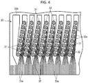
- FIG. 4 is a plan view illustrating the configuration of the nozzle plate 22 in an enlarged manner from the outside.
- the liquid discharge head 1 comprises a liquid discharge unit 11, a liquid supply unit 12, and a drive signal supply unit 13.
- the liquid discharge head 1 is provided, for example, in the liquid discharge recording apparatus 100 as shown in FIG. 5 .
- the liquid discharge unit 11 includes a substrate 21, a nozzle plate 22, and a damper member 23.
- the substrate 21 is formed in a rectangular plate shape. On one main surface (hereinafter referred to as a first surface) of the substrate 21, the nozzle plate 22 is integrally fixed. On the opposite main surface (hereinafter referred to as a second surface) of the substrate 21, the liquid supply unit 12 is integrally fixed.
- the substrate 21 has a plurality of pressure chambers 21a formed therein.
- Each pressure chamber 21a is, for example, a cylindrical through hole formed in the substrate 21. Openings of the pressure chamber 21a at its one end and another end are covered by the nozzle plate 22 and the liquid supply unit 12, respectively.
- the plurality of pressure chambers 21a are arranged in an array in row and column directions.
- the nozzle plate 22 includes a plurality of nozzles 31, a plurality of driving elements 32, and a plurality of electrodes 33.
- Each of the plurality of nozzles 31 is a through hole formed in the nozzle plate 22.
- Each nozzle 31 is formed, for example, in a cylindrical shape or a truncated cone shape. As shown in FIG. 4 , for example, the plurality of nozzles 31 are arranged in the nozzle plate 22 in an array in a similar manner to the plurality of pressure chambers 21a in the row direction and the column direction. The plurality of nozzles 31 face the plurality of pressure chambers 21a when the nozzle plate 22 is fixed to the substrate 21. In one embodiment, the nozzle 31 is aligned coaxial with the pressure chamber 21a.
- the driving elements 32 surround each of the plurality of nozzles 31, respectively.
- Each driving element 32 is an actuator.
- the driving element 32 is, for example, formed in an annular shape.
- the driving element 32 is aligned, for example, coaxially with the nozzle 31.
- each electrode 33 includes, for example, a wiring electrode 33a and a shared electrode 33b.
- the wiring electrode 33a is used as an individual electrode to permit the driving of each driving element 32 independently.
- the damper member 23 is provided on the second surface of the substrate 21. Portions of the damper member 23 are disposed on the second surface of the substrate 21 at positions between adjacent pressure chambers 21a and outside the outermost pressure chambers 21a.
- the damper member 23 is, for example, formed in a rectangular plate shape that is smaller in planar dimension than that of the substrate 21, as shown in FIGS. 2 and 3 .
- the damper member 23 is formed of an elastically deformable material.
- the damper member 23 is formed of a material different from that of the substrate 21.
- the damper member 23 includes, for example, a plurality of damper chambers 23a provided corresponding to the pressure chambers 21a.
- Each damper chamber 23a is, for example, a cylindrical opening having the same inner diameter as that of the pressure chamber 21a.
- the plurality of damper chambers 23a are arranged in the damper member 23 in an array of rows and columns in a similar manner to the plurality of pressure chambers 21a.
- the liquid supply unit 12 covers the second surface of the substrate 21 and the damper member 23.
- the liquid supply unit 12 forms a common liquid chamber 41 between the second surface of the substrate 21 and the damper member 23.
- the liquid supply unit 12 includes a suction port 42 and a discharge port 43.
- the common liquid chamber 41 forms a flow path.
- the common liquid chamber 41 is fluidly connected with the pressure chambers 21a through the damper chambers 23a.
- the suction port 42 is provided on a first side of the common liquid chamber 41.
- the discharge port 43 is provided on a second side of the common liquid chamber 41.
- the drive signal supply unit 13 includes, for example, a flexible substrate 51 and a driver IC 52.
- One end of the flexible substrate 51 is connected to the wiring electrodes 33a and the shared electrodes 33b.
- the driver IC 52 is connected to the wiring electrodes 33a via, for example, the flexible substrate 51.
- portions of the damper member 23 are disposed on the second surface of the substrate 21 between adjacent pressure chambers 21a.
- the driving element 32 is driven to cause liquid droplets to eject from a nozzle 31 corresponding to a particular pressure chamber (hereinafter referred to as a first pressure chamber) among the plurality of the pressure chambers 21a and a residual pressure wave in the first pressure chamber 21a propagates to the liquid in the damper chamber 23a facing the first pressure chamber 21a (hereinafter referred to as a first damper chamber), the damper member 23 can absorb or mitigate the propagating pressure wave.
- the pressure wave transmitted to the common liquid chamber 41 through the first damper chamber 23a is attenuated in the common liquid chamber 41.
- the pressure wave propagated to an adjacent or nearby damper chamber 23a (hereinafter referred to as a second damper chamber) by crosstalk is also absorbed by the damper member 23.
- the liquid discharge head 1 can absorb the pressure wave (or pressure waves) generated by an ejection of droplets from a nozzle (or nozzles) 31 and suppress the crosstalk by inclusion of the damper member 23, and it is thus possible to prevent the pressure wave generated when the droplets are ejected from the nozzle 31 of the first pressure chamber 21a from propagating to an adjacent or nearby pressure chamber 21a. Therefore, the liquid discharge head 1 according to the present embodiment can suppress fluctuations in the speed and volume of the liquid ejection and can eject the liquid droplets from the nozzles 31 with high accuracy.
- the damper member 23 is formed of a material having a reflectance R of 0.5 ⁇ R ⁇ 2 according to one embodiment, the damper member 23 can further effectively absorb the pressure waves generated in the pressure chambers 21a.
- the damper member 23 capable of absorbing the pressure waves is provided, and thus it is possible to suppress influences on neighboring pressure chambers 21a when the liquid droplets are ejected from a nozzle 31.
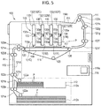
- FIG. 5 is an explanatory diagram illustrating the configuration of an inkjet printer as one example of a liquid discharge recording apparatus 100.
- the liquid discharge recording apparatus 100 includes a housing 111, a recording medium supply unit 112, an image forming unit 113, a recording medium ejection unit 114, a conveyance device 115, and a controller 116.
- the liquid discharge recording apparatus 100 is an ink jet printer that performs an image forming process on a sheet of paper P by discharging a liquid, such as ink, while moving the sheet of paper P, along a predetermined conveyance path A1 extending from the recording medium supply unit 112 through the image forming unit 113 to the recording medium ejection unit 114.
- the sheet of paper P can be referred to as a recording medium.
- the recording medium may, in general, be any object on to which an image or information can be transferred via image forming unit 113.
- the recording medium supply unit 112 comprises a plurality of sheet feeding cassettes 112a.
- the recording medium ejection unit 114 includes an ejection tray 114a.
- the image forming unit 113 comprises a support portion 117 that supports sheets and a plurality of head units 130 disposed above the support portions 117.
- the support portion 117 includes a conveyance belt 118 provided in a loop shape and there is a predetermined region/position utilized for forming an image, a support plate 119 configured to support the conveyance belt 118 from the back side, and a plurality of belt rollers 120 provided on the back side of the conveyance belt 118.
- the head unit 130 comprises: a plurality of liquid discharge heads 1; a plurality of supply tanks 132, which are liquid tanks mounted on each liquid discharge head 1, a plurality of connection flow paths 133, each configured to connect a corresponding one of the liquid discharge heads 1 with a corresponding one of the supply tanks 132; and a plurality of circulation pumps 134, each configured to serve as a circulation unit.
- the head unit 130 in this example is a circulating head unit type through which circulates liquid ink.
- liquid discharge heads 1C, 1M, 1Y, and 1K are provided as the liquid discharge heads 1 and supply tanks 132C, 132M, 132Y, and 132K are respectively provided for containing the inks of the respective colors.
- supply tanks 132 are connected to the liquid discharge heads 1 by the corresponding connection flow paths 133.
- Each connection flow path 133 includes a supply flow path 133a connected to the suction port 42 of the liquid discharge head 1 and a collection flow path 133b connected to the discharge port 43 of the liquid discharge head 1.
- a negative pressure control device such as a pump is also connected to the supply tank 132 according to one embodiment.
- the ink supplied to each nozzle of a liquid discharge head 1 is formed into a meniscus having a predetermined shape by controlling the negative pressure in the supply tank 132 with the negative pressure control device according to the hydrostatic head value of the liquid discharge head 1 and the supply tank 132.
- Each circulation pump 134 is, for example, a liquid feeding pump configured by a piezoelectric pump.
- the circulation pump 134 is provided in the supply flow path 133a.
- the circulation pump 134 is connected to the controller 116 by a wire.
- the circulation pump 134 is controlled by the controller 116.
- the circulation pump 134 circulates the liquid in a circulation flow path including the liquid discharge head 1 and the supply tank 132.
- the conveyance device 115 conveys a sheet of paper P along the conveyance path A1 extending from the sheet feeding cassette 112a of the recording medium supply unit 112 through the image forming unit 113 to the media ejection tray 114a of the recording medium discharge unit 114.
- the conveyance device 115 includes a plurality of guide plate pairs 121a to 121h disposed along the conveyance path A1 and a plurality of conveyance rollers 122a to 122h.
- the conveyance device 115 supports the sheet of paper P to be movable relative to the liquid discharge head 1. That is, the conveyance device 115 moves the sheet of paper P past the liquid discharge head 1 during printing of the like.
- the controller 116 includes a central processing unit (CPU) 116a as an example of a processor, a read only memory (ROM) that stores various programs and the like, a random access memory (RAM) that temporarily stores various types of variable data and image data, and an interface that receives data from the outside and outputs data to the outside.
- the processor performs various operations on data or the like based on programs stored in the memory. By executing a program stored in the memory, the processor functions as a control unit or controller that is capable of executing various operations according to program instructions.
- the controller 116 applies a driving voltage to the driving element 32 corresponding to the target nozzle 31 by the driver IC 52.
- the controller 116 drives the driving element 32, deforms the periphery of the target nozzle 31 in a direction in which the volume of the pressure chamber 21a aligned with the target nozzle 31 increases, and causes the pressure chamber 21a to have a negative pressure, thereby guiding the ink into the pressure chamber 21a.
- the controller 116 drives the driving element 32, deforms the periphery of the target nozzle 31 in a direction in which the volume of the pressure chamber 21a increases, and pressurizes the inside of the pressure chamber 21a, thereby ejecting the droplets from the target nozzle 31.
- the liquid discharge recording apparatus 100 can suppress fluctuations in the speed and volume of the liquid ejection from the nozzles 31 and can eject the liquid droplets with high accuracy.
- the liquid discharge recording apparatus 100 is capable of printing on a sheet of paper P with high accuracy.
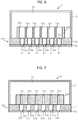
- FIG. 6 is a cross-sectional view illustrating a configuration of the liquid discharge head 1 according to the second embodiment.
- the same components as those of the liquid discharge head 1 according to the first embodiment are denoted by the same reference numerals, and detailed description thereof will be omitted.
- FIG. 6 for the sake of description, certain aspects of the configuration may be enlarged, reduced, or omitted.
- the liquid discharge head 1 includes a liquid discharge unit 11A, a liquid supply unit 12, and a drive signal supply unit 13 (see FIG. 1 ).
- the liquid discharge unit 11A includes a substrate 21, a nozzle plate 22, and a damper member 23A.
- the damper member 23A is formed in a rectangular plate shape having a planar dimension smaller than the substrate 21, as shown in FIG. 6 , for example.
- the damper member 23A includes a plurality of damper chambers 23a provided facing, at one end thereof, the corresponding pressure chambers 21a.
- Each damper chamber 23a is, for example, a cylindrical opening with an inner diameter that is larger than that of the pressure chamber 21a.
- the damper member 23A is formed of the same material as that of the damper member 23 according to the first embodiment.
- each damper chamber 23a is an opening with a diameter larger than that of the pressure chamber 21a.
- the damper chamber 23a of this configuration prevents the obstruction of a smooth liquid flow from the common liquid chamber 41 to the pressure chamber 21a.
- FIG. 7 is a cross-sectional view illustrating a configuration of the liquid discharge head 1 according to the third embodiment.
- the same components as those of the liquid discharge head 1 according to the first embodiment are denoted by the same reference numerals, and detailed description thereof will be omitted.
- FIG. 7 for the sake of description, certain aspects of the configuration may be enlarged, reduced, or omitted.
- the liquid discharge head 1 includes a liquid discharge unit 11B, a liquid supply unit 12, and a drive signal supply unit 13 (see FIG. 1 ). As shown in FIG. 7 , the liquid discharge unit 11B includes a substrate 21, a nozzle plate 22, and a damper member 23B.
- the damper member 23B is provided on the second surface of the substrate 21 at positions between adjacent pressure chambers 21a.
- the damper member 23B is formed in a rectangular plate shape having a planar dimension smaller than that of the substrate 21, as shown in FIG. 7 , for example.
- the damper member 23B includes a plurality of damper chambers 23a provided to face the corresponding pressure chambers 21a.
- Each damper chamber 23a is, for example, a cylindrical opening with an inner diameter smaller than that of the pressure chamber 21a.
- the damper member 23B is formed of the same material as that of the damper member 23 according to the first embodiment.
- the liquid discharge head 1 having the liquid discharge unit 11B according to the third embodiment by integrating therein the damper member 23B capable of absorbing a pressure wave, it is possible to suppress influences on neighboring or nearby pressure chambers 21a when the liquid droplets are ejected from one or more first nozzles 31. Further, since each damper chamber 23a of the damper member 23B is an opening with a smaller diameter than that of the pressure chamber 21a, the thickness of the damper member 23B between the adjacent pressure chambers 21a is larger than that of damper member 23 in the first embodiment. Therefore, the liquid discharge head 1 can further absorb the pressure wave by the damper member 23B as compared with the first embodiment.
- FIG. 8 is a cross-sectional view illustrating a configuration of the liquid discharge head 1 according to the fourth embodiment.
- the same components as those of the liquid discharge head 1 according to the first embodiment are denoted by the same reference numerals, and detailed description thereof will be omitted.
- FIG. 8 for the sake of description, certain aspects of the configuration may be enlarged, reduced, or omitted.
- the liquid discharge head 1 includes a liquid discharge unit 11C, a liquid supply unit 12, and a drive signal supply unit 13 (see FIG. 1 ). As shown in FIG. 8 , the liquid discharge unit 11C includes a substrate 21, a nozzle plate 22, and a damper member 23C.
- the damper member 23C is, for example, formed in a rectangular plate shape having a planar dimension that is smaller than the substrate 21. In this example, the damper member 23C has the same size as the opening area of the common liquid chamber 41, as shown in FIG. 8 .
- the damper member 23C includes a plurality of damper chambers 23a provided so as to face the corresponding pressure chambers 21a. Each of the plurality of damper chamber 23a has, for example, a plurality of through holes 23b, each having a cylindrical shape with a flow diameter smaller than that of the pressure chamber 23a.
- each damper chamber 23a is formed by a set of the plurality of through holes 23b disposed facing an open end of one pressure chamber 21a corresponding to that damper chamber 23a.
- the damper member 23C is formed of the same material as that of the damper member 23 according to the first embodiment.
- the liquid discharge head 1 having the liquid discharge unit 11C equipped with the damper member 23C capable of absorbing the pressure wave according to the fourth embodiment can suppress influences of the liquid droplet ejection from the nozzles 31 on the pressure chambers 21a.
- each of the damper chambers 23a of the damper member 23C is constituted by the plurality of through holes 23b that each have a smaller diameter than that of the corresponding pressure chamber 21a, the damper member 23B can further absorb the pressure waves as compared with the first embodiment. Also, since each damper chamber 23a includes several through holes 23b, the opening area of the damper chamber 23a can still be provided as much as possible, and restriction, if any, of the liquid flow from the common liquid chamber 41 into the pressure chamber 21a can be limited.
- the damper member 23C may be formed to have the same size as the size of the common liquid chamber 41 in the flow direction of the liquid, that is, the same size as the opening area of the opening along the liquid flow direction in the common liquid chamber 41.
- This configuration can prevent undesirable steps from being formed in the flow direction of the common liquid chamber 41. Therefore, the damper member 23C can suppress disturbance of the flow in the common liquid chamber 41.
- the configuration in which the damper member is formed to have the same size as that of the common liquid chamber 41 in the liquid flow direction may be applied to other embodiments.
- FIG. 9 is a cross-sectional view illustrating a configuration of the liquid discharge head 1 according to the fifth embodiment.
- the same components as those of the liquid discharge head 1 according to the first embodiment are denoted by the same reference numerals, and detailed description thereof will be omitted.
- FIG. 9 for the sake of description, certain aspects of the configuration may be enlarged, reduced, or omitted.
- the liquid discharge head 1 includes a liquid discharge unit 11D, a liquid supply unit 12, and a drive signal supply unit 13 (see FIG. 1 ).
- the liquid discharge unit 11D includes a substrate 21, a nozzle plate 22, a first damper member 23, and a second damper member 24.
- the first damper member 23 has the same configuration as that of the damper member 23 of the liquid discharge unit 11 according to the first embodiment, for example.
- the second damper member 24 is provided in the common liquid chamber 41.
- the second damper member 24 has a main surface facing towards the plurality of pressure chambers 21a and the plurality of damper chambers 23a.
- the second damper member 24 is, for example, hollow and is formed in a film-like material that is elastically deformable or at least has flexibility in a portion facing towards the damper member 23.
- the second damper member 24 is formed of, for example, the same material as that of the first damper member 23.
- the absorption of the pressure wave generated by the ejection of the droplets and the suppression of the crosstalk can be performed by the first damper member 23, and the pressure wave generated when the liquid droplets are discharged from the nozzles 31 can be suppressed from propagating to adjacent pressure chambers 21a.
- the second damper member 24 may be applied in combination with the other embodiments (first embodiment through fourth embodiment).
- FIG. 10 is a plan view illustrating a configuration of the liquid discharge head 1 according to the sixth embodiment.
- the same components as those of the liquid discharge head 1 according to the first embodiment are denoted by the same reference numerals, and detailed description thereof will be omitted.
- FIG. 10 for the sake of description, certain aspects of the configuration may be enlarged, reduced, or omitted.
- the liquid discharge head 1 includes a liquid discharge unit 11E, a liquid supply unit 12, and a drive signal supply unit 13 (see FIG. 1 ).
- the liquid discharge unit 11E includes a substrate 21, a nozzle plate 22, and a damper member 23E constituted by a plurality of damper walls 25.
- the damper walls 25 are provided on the second surface of the substrate 21. As shown in FIG. 10 , each damper wall 25 is disposed between adjacent pressure chambers 21a. Each damper wall 25 partitions the adjacent pressure chambers 21a. The adjacent damper walls 25 are spaced apart from each other. Each of the damper walls 25 is, for example, a wall having a rectangular plate shape.
- the damper wall 25 is formed of a material that can be elastically deformed.
- the damper wall 25 is formed of a material different from that of the substrate 21.
- the damper wall 25 is formed of a material having a reflectance R of 0.5 ⁇ R ⁇ 2 when the specific acoustic impedance is represented by Z1, the specific acoustic impedance of the liquid supplied into the pressure chamber is represented by Z2, and the reflectance R is represented by (Z2 - Z1) / (Z1 + Z2).
- the discrete damper walls 25 are provided between the adjacent pressure chambers 21a rather than a damper member 23. Therefore, the liquid discharge head 1 can absorb the pressure wave generated by the jet of droplets and suppress the crosstalk.
- the damper walls 25 are partitions positioned between adjacent pressure chambers 21a. Furthermore, the adjacent damper walls 25 are spaced apart from each other. Therefore, while the damper walls 25 are positioned to limit crosstalk, they do not substantially inhibit the flow of the liquid from the common liquid chamber 41 into the pressure chamber 21a.
- each of the damper members 23, 23A, 23B, 23C, 23D, 23E, and 24 is formed of a material having a reflectance R of 0.5 ⁇ R ⁇ 2 ; however, the present disclosure is not limited to these embodiments.
- the damper members 23, 23A, 23B, 23C, 23D, 23E, and 24 may be formed of material having a Young's modulus less than that of the substrate 21.
- the damper members 23, 23A, 23B, 23C, 23D, 23E, and 24 may be formed of a material having a Young's modulus less than that of the substrate 21 and having a reflectance R of 0.5 ⁇ R ⁇ 2, for example.
- the liquid to be ejected is not limited to the ink for printing.
- a device for ejecting a liquid containing conductive particles for forming a wiring pattern of a printed wiring board may be applicable.
- the liquid discharge head is applied to a liquid discharge recording apparatus, such as an inkjet recording apparatus
- a liquid discharge recording apparatus such as an inkjet recording apparatus
- its application is not limited thereto.
- the liquid discharge head can be used for a 3D printer, an industrial manufacturing machine, a medical device application, and the like, and it is still possible to obtain the advantages of the example embodiments, such as improvements in printing quality and/or a reduction in size, weight, or cost of such other apparatus types.
Landscapes
- Particle Formation And Scattering Control In Inkjet Printers (AREA)
Abstract
Description
- Embodiments described herein generally relate to a liquid discharge head and a liquid discharge recording apparatus.
- A liquid discharge head used in various liquid discharge recording apparatuses, which utilizes densely-arranged nozzles to achieve reduction of head size and increase in an image resolution, is known. In such a liquid discharge head, when the volume of a pressure chamber is changed, causing liquid droplets to eject from the densely-arranged nozzles, a pressure wave is generated and propagates to other pressure chambers such as adjacent or nearby pressure chambers through a common flow path in the liquid discharge head, and the ejection of liquid droplets from the nozzles in the other pressure chambers may be affected.
- Hence, there is a need for a liquid discharge head and a liquid discharge recording apparatus that is capable of suppressing the influence on other pressure chambers when a liquid droplet is ejected from a nozzle via another nearby or adjacent pressure chamber.
-
-
FIG. 1 depicts a liquid discharge head according to a first embodiment. -
FIG. 2 depicts a configuration of a liquid discharge head in a cross-sectional view according to a first embodiment. -
FIG. 3 depicts a configuration of a part of a liquid discharge head in a perspective view according to a first embodiment. -
FIG. 4 depicts a configuration of a nozzle plate of a liquid discharge head in a plan view according to a first embodiment. -
FIG. 5 depicts a configuration of a liquid discharge recording apparatus using a liquid discharge head according to a first embodiment. -
FIG. 6 depicts a configuration of a liquid discharge head in a cross-sectional view according to a second embodiment. -
FIG. 7 depicts a configuration of a liquid discharge head in a cross-sectional view according to a third embodiment. -
FIG. 8 depicts a configuration of a liquid discharge head in a cross-sectional view according to a fourth embodiment. -
FIG. 9 depicts a configuration of a liquid discharge head in a cross-sectional view according to a fifth embodiment. -
FIG. 10 depicts a configuration of a part of a liquid discharge head in a plan view according to a sixth embodiment. - In one embodiment, a liquid discharge head comprises a substrate, a nozzle plate, and a damper member. The substrate comprises a plurality of pressure chambers. The nozzle plate is provided on a first surface of the substrate and comprises a plurality of nozzles. Each of the plurality of nozzles is aligned with a corresponding one of the plurality of pressure chambers. The damper member is on a second surface of the substrate and configured to absorb a pressure wave. Portions of the damper member are on the second surface at positions between adjacent pressure chambers generated in the pressure chamber.
- Preferably, the damper member comprises a plurality of damper chambers respectively facing the plurality of pressure chambers.
- Preferably, the damper chamber is a cylindrical opening in the damper member having an inner diameter that is substantially equal to a diameter of the one of the pressure chambers.
- Preferably, the damper chamber is a cylindrical opening in the damper member having an inner diameter that is greater than a diameter of the one of the pressure chambers.
- Preferably, the damper chamber is a cylindrical opening in the damper member having an inner diameter that is less than a diameter of the one of the pressure chambers.
- Preferably, the damper chamber comprises a plurality of through holes in the damper member, each through hole having an inner diameter that is less than a diameter of the one of the pressure chambers.
- Preferably, the liquid discharge head further comprises a second damper member spaced from the damper member in a common pressure chamber, the second damper member comprising a pressure wave absorbing material.
- Preferably, the portions of the damper member are damper walls spaced from each other in a direction parallel to the second surface.
- Preferably, the damper member is formed of an elastically deformable material.
- Preferably, the damper member is formed of a material that is different from a material of the substrate.
- Preferably, the material has a reflectance R of 0.5 ≤ R ≤ 2 when a specific acoustic impedance of the damping member is represented by Z1, a specific acoustic impedance of the liquid supplied in the pressure chamber is represented by Z2, and the reflectance R is calculated as (Z2 - Z1) / (Z1 + Z2).
- Preferably, a material forming the damper member has a Young's modulus less than that of a material forming the substrate.
- Preferably, the liquid discharge head further comprises a liquid supply unit configured to cover the second surface of the substrate and the damper member and forms a common liquid chamber that is fluidly connected to the plurality of nozzles.
- Preferably, the nozzle plate further comprises a plurality of driving elements configured to drive the ejection of liquid from the plurality of nozzles.
- In another exemplary embodiment, there is also provided a liquid discharge recording apparatus, comprising the aforementioned liquid discharge head; and a media support device configured to position an object relative to the liquid discharge head for liquid droplet discharge.
- Hereinafter, a
liquid discharge head 1 and a liquiddischarge recording apparatus 100 according to a first embodiment will be described with reference toFIGS. 1 to 4 . In the drawings, for the sake of description, various aspects of configuration may be shown as enlarged, reduced, or omitted as appropriate since the drawings are, in general, schematic and not intended to be to scale. -
FIG. 1 is a perspective view illustrating a configuration of aliquid discharge head 1 according to the first embodiment.FIG. 2 is a cross-sectional view schematically illustrating the configuration of aliquid discharge unit 11 and aliquid supply unit 12 of theliquid discharge head 1, andFIG. 3 is a perspective view schematically showing the configuration of asubstrate 21, anozzle plate 22 and adamper member 23 of theliquid discharge unit 11.FIG. 4 is a plan view illustrating the configuration of thenozzle plate 22 in an enlarged manner from the outside. - As shown in
FIGS. 1 and 2 , theliquid discharge head 1 comprises aliquid discharge unit 11, aliquid supply unit 12, and a drivesignal supply unit 13. Theliquid discharge head 1 is provided, for example, in the liquiddischarge recording apparatus 100 as shown inFIG. 5 . - As shown in
FIGS. 2 and3 , theliquid discharge unit 11 includes asubstrate 21, anozzle plate 22, and adamper member 23. - In the present embodiment, the
substrate 21 is formed in a rectangular plate shape. On one main surface (hereinafter referred to as a first surface) of thesubstrate 21, thenozzle plate 22 is integrally fixed. On the opposite main surface (hereinafter referred to as a second surface) of thesubstrate 21, theliquid supply unit 12 is integrally fixed. Thesubstrate 21 has a plurality ofpressure chambers 21a formed therein. - Each
pressure chamber 21a is, for example, a cylindrical through hole formed in thesubstrate 21. Openings of thepressure chamber 21a at its one end and another end are covered by thenozzle plate 22 and theliquid supply unit 12, respectively. The plurality ofpressure chambers 21a are arranged in an array in row and column directions. - As shown in
FIGS. 1 to 4 , thenozzle plate 22 includes a plurality ofnozzles 31, a plurality ofdriving elements 32, and a plurality ofelectrodes 33. - Each of the plurality of
nozzles 31 is a through hole formed in thenozzle plate 22. Eachnozzle 31 is formed, for example, in a cylindrical shape or a truncated cone shape. As shown inFIG. 4 , for example, the plurality ofnozzles 31 are arranged in thenozzle plate 22 in an array in a similar manner to the plurality ofpressure chambers 21a in the row direction and the column direction. The plurality ofnozzles 31 face the plurality ofpressure chambers 21a when thenozzle plate 22 is fixed to thesubstrate 21. In one embodiment, thenozzle 31 is aligned coaxial with thepressure chamber 21a. - As shown in
FIG. 4 , thedriving elements 32 surround each of the plurality ofnozzles 31, respectively. Eachdriving element 32 is an actuator. Thedriving element 32 is, for example, formed in an annular shape. Thedriving element 32 is aligned, for example, coaxially with thenozzle 31. - As shown in
FIG. 4 , theelectrodes 33 are respectively connected to thedriving elements 32. Eachelectrode 33 includes, for example, awiring electrode 33a and a sharedelectrode 33b. Thewiring electrode 33a is used as an individual electrode to permit the driving of each drivingelement 32 independently. - The
damper member 23 is provided on the second surface of thesubstrate 21. Portions of thedamper member 23 are disposed on the second surface of thesubstrate 21 at positions betweenadjacent pressure chambers 21a and outside theoutermost pressure chambers 21a. Thedamper member 23 is, for example, formed in a rectangular plate shape that is smaller in planar dimension than that of thesubstrate 21, as shown inFIGS. 2 and3 . - The
damper member 23 is formed of an elastically deformable material. Thedamper member 23 is formed of a material different from that of thesubstrate 21. In one embodiment, thedamper member 23 is formed of a material having a reflectance R of 0.5 ≤ R ≤ 2 when a specific acoustic impedance of thedamper member 23 is represented by Z1, a specific acoustic impedance of the liquid supplied in the pressure chamber is represented by Z2, and the reflectance R = (Z2 - Z1) / (Z1 + Z2) is satisfied. - The
damper member 23 includes, for example, a plurality ofdamper chambers 23a provided corresponding to thepressure chambers 21a. Eachdamper chamber 23a is, for example, a cylindrical opening having the same inner diameter as that of thepressure chamber 21a. The plurality ofdamper chambers 23a are arranged in thedamper member 23 in an array of rows and columns in a similar manner to the plurality ofpressure chambers 21a. - The
liquid supply unit 12 covers the second surface of thesubstrate 21 and thedamper member 23. Theliquid supply unit 12 forms acommon liquid chamber 41 between the second surface of thesubstrate 21 and thedamper member 23. In addition, theliquid supply unit 12 includes asuction port 42 and adischarge port 43. - The
common liquid chamber 41 forms a flow path. Thecommon liquid chamber 41 is fluidly connected with thepressure chambers 21a through thedamper chambers 23a. Thesuction port 42 is provided on a first side of thecommon liquid chamber 41. Thedischarge port 43 is provided on a second side of thecommon liquid chamber 41. - The drive
signal supply unit 13 includes, for example, aflexible substrate 51 and adriver IC 52. One end of theflexible substrate 51 is connected to thewiring electrodes 33a and the sharedelectrodes 33b. Thedriver IC 52 is connected to thewiring electrodes 33a via, for example, theflexible substrate 51. - In the
liquid discharge head 1 according to the first embodiment, portions of thedamper member 23 are disposed on the second surface of thesubstrate 21 betweenadjacent pressure chambers 21a. When the drivingelement 32 is driven to cause liquid droplets to eject from anozzle 31 corresponding to a particular pressure chamber (hereinafter referred to as a first pressure chamber) among the plurality of thepressure chambers 21a and a residual pressure wave in thefirst pressure chamber 21a propagates to the liquid in thedamper chamber 23a facing thefirst pressure chamber 21a (hereinafter referred to as a first damper chamber), thedamper member 23 can absorb or mitigate the propagating pressure wave. Further, the pressure wave transmitted to thecommon liquid chamber 41 through thefirst damper chamber 23a is attenuated in thecommon liquid chamber 41. In addition, the pressure wave propagated to an adjacent ornearby damper chamber 23a (hereinafter referred to as a second damper chamber) by crosstalk is also absorbed by thedamper member 23. - Accordingly, the
liquid discharge head 1 can absorb the pressure wave (or pressure waves) generated by an ejection of droplets from a nozzle (or nozzles) 31 and suppress the crosstalk by inclusion of thedamper member 23, and it is thus possible to prevent the pressure wave generated when the droplets are ejected from thenozzle 31 of thefirst pressure chamber 21a from propagating to an adjacent ornearby pressure chamber 21a. Therefore, theliquid discharge head 1 according to the present embodiment can suppress fluctuations in the speed and volume of the liquid ejection and can eject the liquid droplets from thenozzles 31 with high accuracy. - Since the
damper member 23 is formed of a material having a reflectance R of 0.5 ≤ R ≤ 2 according to one embodiment, thedamper member 23 can further effectively absorb the pressure waves generated in thepressure chambers 21a. - As described above, according to the
liquid discharge head 1 of the first embodiment, thedamper member 23 capable of absorbing the pressure waves is provided, and thus it is possible to suppress influences on neighboringpressure chambers 21a when the liquid droplets are ejected from anozzle 31. - Next, a liquid
discharge recording apparatus 100 equipped with theliquid discharge head 1 will be described with reference toFIG. 5. FIG. 5 is an explanatory diagram illustrating the configuration of an inkjet printer as one example of a liquiddischarge recording apparatus 100. As shown inFIG. 5 , the liquiddischarge recording apparatus 100 includes ahousing 111, a recordingmedium supply unit 112, animage forming unit 113, a recordingmedium ejection unit 114, aconveyance device 115, and acontroller 116. - The liquid
discharge recording apparatus 100 is an ink jet printer that performs an image forming process on a sheet of paper P by discharging a liquid, such as ink, while moving the sheet of paper P, along a predetermined conveyance path A1 extending from the recordingmedium supply unit 112 through theimage forming unit 113 to the recordingmedium ejection unit 114. In this context, the sheet of paper P can be referred to as a recording medium. In other examples, the recording medium may, in general, be any object on to which an image or information can be transferred viaimage forming unit 113. - The recording
medium supply unit 112 comprises a plurality ofsheet feeding cassettes 112a. The recordingmedium ejection unit 114 includes anejection tray 114a. Theimage forming unit 113 comprises asupport portion 117 that supports sheets and a plurality ofhead units 130 disposed above thesupport portions 117. - The
support portion 117 includes a conveyance belt 118 provided in a loop shape and there is a predetermined region/position utilized for forming an image, asupport plate 119 configured to support the conveyance belt 118 from the back side, and a plurality ofbelt rollers 120 provided on the back side of the conveyance belt 118. - The
head unit 130 comprises: a plurality of liquid discharge heads 1; a plurality ofsupply tanks 132, which are liquid tanks mounted on eachliquid discharge head 1, a plurality ofconnection flow paths 133, each configured to connect a corresponding one of the liquid discharge heads 1 with a corresponding one of thesupply tanks 132; and a plurality of circulation pumps 134, each configured to serve as a circulation unit. Thehead unit 130 in this example is a circulating head unit type through which circulates liquid ink. - In the present embodiment, liquid discharge heads 1C, 1M, 1Y, and 1K, respectively for cyan, magenta, yellow, and black, are provided as the liquid discharge heads 1 and
supply tanks supply tanks 132 are connected to the liquid discharge heads 1 by the correspondingconnection flow paths 133. Eachconnection flow path 133 includes asupply flow path 133a connected to thesuction port 42 of theliquid discharge head 1 and acollection flow path 133b connected to thedischarge port 43 of theliquid discharge head 1. - A negative pressure control device such as a pump is also connected to the
supply tank 132 according to one embodiment. The ink supplied to each nozzle of aliquid discharge head 1 is formed into a meniscus having a predetermined shape by controlling the negative pressure in thesupply tank 132 with the negative pressure control device according to the hydrostatic head value of theliquid discharge head 1 and thesupply tank 132. - Each
circulation pump 134 is, for example, a liquid feeding pump configured by a piezoelectric pump. Thecirculation pump 134 is provided in thesupply flow path 133a. Thecirculation pump 134 is connected to thecontroller 116 by a wire. Thecirculation pump 134 is controlled by thecontroller 116. Thecirculation pump 134 circulates the liquid in a circulation flow path including theliquid discharge head 1 and thesupply tank 132. - The
conveyance device 115 conveys a sheet of paper P along the conveyance path A1 extending from thesheet feeding cassette 112a of the recordingmedium supply unit 112 through theimage forming unit 113 to themedia ejection tray 114a of the recordingmedium discharge unit 114. Theconveyance device 115 includes a plurality ofguide plate pairs 121a to 121h disposed along the conveyance path A1 and a plurality ofconveyance rollers 122a to 122h. Theconveyance device 115 supports the sheet of paper P to be movable relative to theliquid discharge head 1. That is, theconveyance device 115 moves the sheet of paper P past theliquid discharge head 1 during printing of the like. - The
controller 116 includes a central processing unit (CPU) 116a as an example of a processor, a read only memory (ROM) that stores various programs and the like, a random access memory (RAM) that temporarily stores various types of variable data and image data, and an interface that receives data from the outside and outputs data to the outside. The processor performs various operations on data or the like based on programs stored in the memory. By executing a program stored in the memory, the processor functions as a control unit or controller that is capable of executing various operations according to program instructions. - In the liquid
discharge recording apparatus 100 equipped with theliquid discharge head 1 according to the present embodiment, during the operation of the liquid discharge from the nozzle (or nozzles) 31 (hereinafter also referred to as a target nozzle), thecontroller 116 applies a driving voltage to the drivingelement 32 corresponding to thetarget nozzle 31 by thedriver IC 52. For example, thecontroller 116 drives the drivingelement 32, deforms the periphery of thetarget nozzle 31 in a direction in which the volume of thepressure chamber 21a aligned with thetarget nozzle 31 increases, and causes thepressure chamber 21a to have a negative pressure, thereby guiding the ink into thepressure chamber 21a. Subsequently, thecontroller 116 drives the drivingelement 32, deforms the periphery of thetarget nozzle 31 in a direction in which the volume of thepressure chamber 21a increases, and pressurizes the inside of thepressure chamber 21a, thereby ejecting the droplets from thetarget nozzle 31. - By using the
liquid discharge head 1 equipped with thedamper member 23, the liquiddischarge recording apparatus 100 according to the present embodiment can suppress fluctuations in the speed and volume of the liquid ejection from thenozzles 31 and can eject the liquid droplets with high accuracy. Thus, the liquiddischarge recording apparatus 100 is capable of printing on a sheet of paper P with high accuracy. - Next, a
liquid discharge head 1 according to a second embodiment will be described with reference toFIG. 6. FIG. 6 is a cross-sectional view illustrating a configuration of theliquid discharge head 1 according to the second embodiment. In theliquid discharge head 1 according to the second embodiment, the same components as those of theliquid discharge head 1 according to the first embodiment are denoted by the same reference numerals, and detailed description thereof will be omitted. InFIG. 6 , for the sake of description, certain aspects of the configuration may be enlarged, reduced, or omitted. - The
liquid discharge head 1 according to the second embodiment includes aliquid discharge unit 11A, aliquid supply unit 12, and a drive signal supply unit 13 (seeFIG. 1 ). As shown inFIG. 6 , theliquid discharge unit 11A includes asubstrate 21, anozzle plate 22, and adamper member 23A. - Portions of the
damper member 23A are provided on the second surface of thesubstrate 21 at positions betweenadjacent pressure chambers 21a. Thedamper member 23A is formed in a rectangular plate shape having a planar dimension smaller than thesubstrate 21, as shown inFIG. 6 , for example. Thedamper member 23A includes a plurality ofdamper chambers 23a provided facing, at one end thereof, thecorresponding pressure chambers 21a. Eachdamper chamber 23a is, for example, a cylindrical opening with an inner diameter that is larger than that of thepressure chamber 21a. Thedamper member 23A is formed of the same material as that of thedamper member 23 according to the first embodiment. - In the
liquid discharge head 1 having theliquid discharge unit 11A according to the second embodiment, as with theliquid discharge head 1 according to the first embodiment, by integrating therein thedamper member 23A capable of absorbing a pressure wave, it is possible to suppress influences on neighboring ornearby pressure chambers 21a when the liquid droplets are ejected from one or morefirst nozzles 31. Eachdamper chamber 23a is an opening with a diameter larger than that of thepressure chamber 21a. Thedamper chamber 23a of this configuration prevents the obstruction of a smooth liquid flow from thecommon liquid chamber 41 to thepressure chamber 21a. - Next, a
liquid discharge head 1 according to a third embodiment will be described with reference toFIG. 7. FIG. 7 is a cross-sectional view illustrating a configuration of theliquid discharge head 1 according to the third embodiment. In theliquid discharge head 1 according to the third embodiment, the same components as those of theliquid discharge head 1 according to the first embodiment are denoted by the same reference numerals, and detailed description thereof will be omitted.FIG. 7 , for the sake of description, certain aspects of the configuration may be enlarged, reduced, or omitted. - The
liquid discharge head 1 according to the third embodiment includes aliquid discharge unit 11B, aliquid supply unit 12, and a drive signal supply unit 13 (seeFIG. 1 ). As shown inFIG. 7 , theliquid discharge unit 11B includes asubstrate 21, anozzle plate 22, and adamper member 23B. - Portions of the
damper member 23B are provided on the second surface of thesubstrate 21 at positions betweenadjacent pressure chambers 21a. Thedamper member 23B is formed in a rectangular plate shape having a planar dimension smaller than that of thesubstrate 21, as shown inFIG. 7 , for example. Thedamper member 23B includes a plurality ofdamper chambers 23a provided to face thecorresponding pressure chambers 21a. Eachdamper chamber 23a is, for example, a cylindrical opening with an inner diameter smaller than that of thepressure chamber 21a. Thedamper member 23B is formed of the same material as that of thedamper member 23 according to the first embodiment. - In the
liquid discharge head 1 having theliquid discharge unit 11B according to the third embodiment, as with theliquid discharge head 1 according to the first embodiment, by integrating therein thedamper member 23B capable of absorbing a pressure wave, it is possible to suppress influences on neighboring ornearby pressure chambers 21a when the liquid droplets are ejected from one or morefirst nozzles 31. Further, since eachdamper chamber 23a of thedamper member 23B is an opening with a smaller diameter than that of thepressure chamber 21a, the thickness of thedamper member 23B between theadjacent pressure chambers 21a is larger than that ofdamper member 23 in the first embodiment. Therefore, theliquid discharge head 1 can further absorb the pressure wave by thedamper member 23B as compared with the first embodiment. - Next, a
liquid discharge head 1 according to a fourth embodiment will be described with reference toFIG. 8. FIG. 8 is a cross-sectional view illustrating a configuration of theliquid discharge head 1 according to the fourth embodiment. In theliquid discharge head 1 according to the fourth embodiment, the same components as those of theliquid discharge head 1 according to the first embodiment are denoted by the same reference numerals, and detailed description thereof will be omitted.FIG. 8 , for the sake of description, certain aspects of the configuration may be enlarged, reduced, or omitted. - The
liquid discharge head 1 according to the fourth embodiment includes aliquid discharge unit 11C, aliquid supply unit 12, and a drive signal supply unit 13 (seeFIG. 1 ). As shown inFIG. 8 , theliquid discharge unit 11C includes asubstrate 21, anozzle plate 22, and adamper member 23C. - Portions of the
damper member 23C are provided on the second surface of thesubstrate 21 at positions betweenadjacent pressure chambers 21a. Thedamper member 23C is, for example, formed in a rectangular plate shape having a planar dimension that is smaller than thesubstrate 21. In this example, thedamper member 23C has the same size as the opening area of thecommon liquid chamber 41, as shown inFIG. 8 . Thedamper member 23C includes a plurality ofdamper chambers 23a provided so as to face thecorresponding pressure chambers 21a. Each of the plurality ofdamper chamber 23a has, for example, a plurality of through holes 23b, each having a cylindrical shape with a flow diameter smaller than that of thepressure chamber 23a. That is, eachdamper chamber 23a is formed by a set of the plurality of through holes 23b disposed facing an open end of onepressure chamber 21a corresponding to thatdamper chamber 23a. Note that thedamper member 23C is formed of the same material as that of thedamper member 23 according to the first embodiment. - In a similar manner to the
liquid discharge head 1 according to the first embodiment, theliquid discharge head 1 having theliquid discharge unit 11C equipped with thedamper member 23C capable of absorbing the pressure wave according to the fourth embodiment, can suppress influences of the liquid droplet ejection from thenozzles 31 on thepressure chambers 21a. - Further, since each of the
damper chambers 23a of thedamper member 23C is constituted by the plurality of through holes 23b that each have a smaller diameter than that of thecorresponding pressure chamber 21a, thedamper member 23B can further absorb the pressure waves as compared with the first embodiment. Also, since eachdamper chamber 23a includes several through holes 23b, the opening area of thedamper chamber 23a can still be provided as much as possible, and restriction, if any, of the liquid flow from thecommon liquid chamber 41 into thepressure chamber 21a can be limited. - In the present embodiment, the
damper member 23C may be formed to have the same size as the size of thecommon liquid chamber 41 in the flow direction of the liquid, that is, the same size as the opening area of the opening along the liquid flow direction in thecommon liquid chamber 41. This configuration can prevent undesirable steps from being formed in the flow direction of thecommon liquid chamber 41. Therefore, thedamper member 23C can suppress disturbance of the flow in thecommon liquid chamber 41. Note that the configuration in which the damper member is formed to have the same size as that of thecommon liquid chamber 41 in the liquid flow direction may be applied to other embodiments. - Next, a
liquid discharge head 1 according to a fifth embodiment will be described with reference toFIG. 9. FIG. 9 is a cross-sectional view illustrating a configuration of theliquid discharge head 1 according to the fifth embodiment. In theliquid discharge head 1 according to the fifth embodiment, the same components as those of theliquid discharge head 1 according to the first embodiment are denoted by the same reference numerals, and detailed description thereof will be omitted. InFIG. 9 , for the sake of description, certain aspects of the configuration may be enlarged, reduced, or omitted. - The
liquid discharge head 1 according to the fifth embodiment includes aliquid discharge unit 11D, aliquid supply unit 12, and a drive signal supply unit 13 (seeFIG. 1 ). As shown inFIG. 9 , theliquid discharge unit 11D includes asubstrate 21, anozzle plate 22, afirst damper member 23, and asecond damper member 24. - The
first damper member 23 has the same configuration as that of thedamper member 23 of theliquid discharge unit 11 according to the first embodiment, for example. - The
second damper member 24 is provided in thecommon liquid chamber 41. Thesecond damper member 24 has a main surface facing towards the plurality ofpressure chambers 21a and the plurality ofdamper chambers 23a. Thesecond damper member 24 is, for example, hollow and is formed in a film-like material that is elastically deformable or at least has flexibility in a portion facing towards thedamper member 23. Thesecond damper member 24 is formed of, for example, the same material as that of thefirst damper member 23. - According to the
liquid discharge head 1 having theliquid discharge unit 11D according to the fifth embodiment, similarly to theliquid discharge head 1 according to the first embodiment, the absorption of the pressure wave generated by the ejection of the droplets and the suppression of the crosstalk can be performed by thefirst damper member 23, and the pressure wave generated when the liquid droplets are discharged from thenozzles 31 can be suppressed from propagating toadjacent pressure chambers 21a. - In addition, the pressure waves propagated from the
damper chambers 23a to thecommon liquid chamber 41 are absorbed by thesecond damper member 24. Therefore, the pressure waves transmitted to thecommon liquid chamber 41 through thedamper chambers 23a are attenuated by thesecond damper member 24. Accordingly, the propagation of the pressure waves generated in thepressure chambers 21a to the adjacent ornearby damper chambers 23a andpressure chambers 21a by the crosstalk can be effectively suppressed. Note that thesecond damper member 24 may be applied in combination with the other embodiments (first embodiment through fourth embodiment). - Next, a
liquid discharge head 1 according to a sixth embodiment will be described with reference toFIG. 10. FIG. 10 is a plan view illustrating a configuration of theliquid discharge head 1 according to the sixth embodiment. In theliquid discharge head 1 according to the sixth embodiment, the same components as those of theliquid discharge head 1 according to the first embodiment are denoted by the same reference numerals, and detailed description thereof will be omitted. InFIG. 10 , for the sake of description, certain aspects of the configuration may be enlarged, reduced, or omitted. - The
liquid discharge head 1 according to the sixth embodiment includes aliquid discharge unit 11E, aliquid supply unit 12, and a drive signal supply unit 13 (seeFIG. 1 ). As shown inFIG. 10 , theliquid discharge unit 11E includes asubstrate 21, anozzle plate 22, and adamper member 23E constituted by a plurality ofdamper walls 25. - The
damper walls 25 are provided on the second surface of thesubstrate 21. As shown inFIG. 10 , eachdamper wall 25 is disposed betweenadjacent pressure chambers 21a. Eachdamper wall 25 partitions theadjacent pressure chambers 21a. Theadjacent damper walls 25 are spaced apart from each other. Each of thedamper walls 25 is, for example, a wall having a rectangular plate shape. - The
damper wall 25 is formed of a material that can be elastically deformed. Thedamper wall 25 is formed of a material different from that of thesubstrate 21. As a specific example, thedamper wall 25 is formed of a material having a reflectance R of 0.5 ≤ R ≤ 2 when the specific acoustic impedance is represented by Z1, the specific acoustic impedance of the liquid supplied into the pressure chamber is represented by Z2, and the reflectance R is represented by (Z2 - Z1) / (Z1 + Z2). - In the
liquid discharge head 1 according to the sixth embodiment as described above, thediscrete damper walls 25 are provided between theadjacent pressure chambers 21a rather than adamper member 23. Therefore, theliquid discharge head 1 can absorb the pressure wave generated by the jet of droplets and suppress the crosstalk. Thedamper walls 25 are partitions positioned betweenadjacent pressure chambers 21a. Furthermore, theadjacent damper walls 25 are spaced apart from each other. Therefore, while thedamper walls 25 are positioned to limit crosstalk, they do not substantially inhibit the flow of the liquid from thecommon liquid chamber 41 into thepressure chamber 21a. - In the embodiments described above, each of the
damper members damper members substrate 21. Furthermore, thedamper members substrate 21 and having a reflectance R of 0.5 ≤ R ≤ 2, for example. - The liquid to be ejected is not limited to the ink for printing. For example, a device for ejecting a liquid containing conductive particles for forming a wiring pattern of a printed wiring board may be applicable.
- While in the embodiments described above, the liquid discharge head is applied to a liquid discharge recording apparatus, such as an inkjet recording apparatus, its application is not limited thereto. For example, the liquid discharge head can be used for a 3D printer, an industrial manufacturing machine, a medical device application, and the like, and it is still possible to obtain the advantages of the example embodiments, such as improvements in printing quality and/or a reduction in size, weight, or cost of such other apparatus types.
- According to the liquid discharge head or the liquid discharge recording apparatus of the embodiments described above, influences of the droplet ejection from the nozzles on neighboring or nearby pressure chambers can be effectively suppressed.
- While certain embodiments have been described, these embodiments have been presented by way of example only and are not intended to limit the scope of the inventions. Indeed, the novel embodiments described herein may be embodied in a variety of other forms; furthermore, various omissions, substitutions and changes in the form of the embodiments described herein may be made without departing from the scope of the inventions. The accompanying claims and their equivalents are intended to cover such forms or modifications as would fall within the scope of the inventions.
Claims (15)
- A liquid discharge head, comprising:a substrate comprising a plurality of pressure chambers;a nozzle plate on a first surface of the substrate and comprising a plurality of nozzles, each of the plurality of nozzles aligned with a corresponding one of the plurality of pressure chambers; anda damper member on a second surface of the substrate configured to absorb a pressure wave, portions of the damper member being on the second surface at positions between adjacent pressure chambers.
- The liquid discharge head according to claim 1, wherein the damper member comprises a plurality of damper chambers respectively facing the plurality of pressure chambers.
- The liquid discharge head according to claim 2, wherein the damper chamber is a cylindrical opening in the damper member having an inner diameter that is substantially equal to a diameter of the one of the pressure chambers.
- The liquid discharge head according to claim 2, wherein the damper chamber is a cylindrical opening in the damper member having an inner diameter that is greater than a diameter of the one of the pressure chambers.
- The liquid discharge head according to claim 2, wherein the damper chamber is a cylindrical opening in the damper member having an inner diameter that is less than a diameter of the one of the pressure chambers.
- The liquid discharge head according to claim 2, wherein the damper chamber comprises a plurality of through holes in the damper member, each through hole having an inner diameter that is less than a diameter of the one of the pressure chambers.
- The liquid discharge head according to any one of claims 1 to 6, further comprising a second damper member spaced from the damper member in a common pressure chamber, the second damper member comprising a pressure wave absorbing material.
- The liquid discharge head according to claim 1, wherein the portions of the damper member are damper walls spaced from each other in a direction parallel to the second surface.
- The liquid discharge head according to any one of claims 1 to 8, wherein the damper member is formed of an elastically deformable material.
- The liquid discharge head according to any one of claims 1 to 9, wherein the damper member is formed of a material that is different from a material of the substrate.
- The liquid discharge head according to claim 10, wherein the material has a reflectance R of 0.5 ≤ R ≤ 2 when a specific acoustic impedance of the damping member is represented by Z1, a specific acoustic impedance of the liquid supplied in the pressure chamber is represented by Z2, and the reflectance R is calculated as (Z2 - Z1) / (Z1 + Z2).
- The liquid discharge head according to any one of claims 1 to 11, wherein a material forming the damper member has a Young's modulus less than that of a material forming the substrate.
- The liquid discharge head according to any one of claims 1 to 12, further comprising a liquid supply unit configured to cover the second surface of the substrate and the damper member and forms a common liquid chamber that is fluidly connected to the plurality of nozzles.
- The liquid discharge head according to claim 13, wherein the nozzle plate further comprises a plurality of driving elements configured to drive the ejection of liquid from the plurality of nozzles.
- A liquid discharge recording apparatus, comprising:the liquid discharge head according to any one of claims 1 to 14; anda media support device configured to position an object relative to the liquid discharge head for liquid droplet discharge.
Applications Claiming Priority (1)
| Application Number | Priority Date | Filing Date | Title |
|---|---|---|---|
| JP2019163933A JP2021041569A (en) | 2019-09-09 | 2019-09-09 | Liquid discharge head and liquid discharge recording device |
Publications (2)
| Publication Number | Publication Date |
|---|---|
| EP3789203A1 true EP3789203A1 (en) | 2021-03-10 |
| EP3789203B1 EP3789203B1 (en) | 2023-03-15 |
Family
ID=72322278
Family Applications (1)
| Application Number | Title | Priority Date | Filing Date |
|---|---|---|---|
| EP20192051.9A Active EP3789203B1 (en) | 2019-09-09 | 2020-08-21 | Liquid discharge head and liquid discharge recording apparatus |
Country Status (4)
| Country | Link |
|---|---|
| US (1) | US11318742B2 (en) |
| EP (1) | EP3789203B1 (en) |
| JP (1) | JP2021041569A (en) |
| CN (1) | CN112455089B (en) |
Cited By (2)
| Publication number | Priority date | Publication date | Assignee | Title |
|---|---|---|---|---|
| WO2024089498A1 (en) * | 2022-10-25 | 2024-05-02 | Ricoh Company, Ltd. | Liquid discharge head and liquid discharge apparatus |
| WO2024185761A1 (en) * | 2023-03-06 | 2024-09-12 | Ricoh Company, Ltd. | Liquid ejection head, liquid ejection apparatus, and method of manufacturing liquid ejection head |
Families Citing this family (3)
| Publication number | Priority date | Publication date | Assignee | Title |
|---|---|---|---|---|
| JP2024099377A (en) | 2023-01-12 | 2024-07-25 | 株式会社リコー | LIQUID DISCHARGE HEAD AND DEVICE FOR DISCHARGING LIQUID |
| WO2024189450A1 (en) | 2023-03-15 | 2024-09-19 | Ricoh Company, Ltd. | Liquid discharge head, liquid discharge apparatus, and liquid filling method |
| US20260174510A1 (en) | 2024-12-20 | 2026-06-25 | Siemens Heatlhineers Endovascular Robotics, Inc. | Cart for tracking a catherization table |
Citations (6)
| Publication number | Priority date | Publication date | Assignee | Title |
|---|---|---|---|---|
| JP2006212781A (en) * | 2005-02-01 | 2006-08-17 | Fuji Xerox Co Ltd | Inkjet recording head, and inkjet recorder |
| WO2008044073A1 (en) * | 2006-10-12 | 2008-04-17 | The Technology Partnership Plc | Liquid projection apparatus |
| US20140253639A1 (en) * | 2013-03-08 | 2014-09-11 | Toshiba Tec Kabushiki Kaisha | Ink jet head and ink jet printing apparatus having the same |
| US20160279938A1 (en) * | 2015-03-26 | 2016-09-29 | Seiko Epson Corporation | Liquid ejecting head and liquid ejecting apparatus |
| EP3372407A1 (en) * | 2017-03-07 | 2018-09-12 | OCE Holding B.V. | Inkjet print head assembly and method of manufacturing such inket print head |
| US20180281402A1 (en) * | 2017-03-28 | 2018-10-04 | Stmicroelectronics S.R.L. | Fluid ejection device, printhead, printer, and method for manufacturing the ejection device |
Family Cites Families (13)
| Publication number | Priority date | Publication date | Assignee | Title |
|---|---|---|---|---|
| JPH02111550A (en) * | 1988-10-20 | 1990-04-24 | Canon Inc | inkjet recording head |
| JP5011723B2 (en) * | 2005-12-22 | 2012-08-29 | 富士ゼロックス株式会社 | Droplet discharge head and droplet discharge apparatus |
| JP2010188547A (en) * | 2009-02-16 | 2010-09-02 | Ricoh Co Ltd | Liquid droplet delivery head, liquid droplet delivery apparatus equipped with the same, and image forming apparatus |
| JP6248811B2 (en) | 2014-05-27 | 2017-12-20 | コニカミノルタ株式会社 | Ink jet head and damper member manufacturing method |
| EP2851200B1 (en) | 2013-08-27 | 2020-04-01 | Konica Minolta, Inc. | Inkjet head and method for driving inkjet head |
| JP6213230B2 (en) * | 2013-09-13 | 2017-10-18 | 株式会社リコー | Liquid ejection head and image forming apparatus |
| US9421768B2 (en) * | 2014-04-02 | 2016-08-23 | Kabushiki Kaisha Toshiba | Inkjet printer head |
| JP6447218B2 (en) * | 2015-02-17 | 2019-01-09 | コニカミノルタ株式会社 | Ink jet head and damper member manufacturing method |
| JP6477041B2 (en) * | 2015-03-06 | 2019-03-06 | セイコーエプソン株式会社 | Liquid ejector |
| JP6724923B2 (en) * | 2015-09-18 | 2020-07-15 | コニカミノルタ株式会社 | Inkjet head and inkjet recording device |
| JP2018153926A (en) * | 2017-03-15 | 2018-10-04 | セイコーエプソン株式会社 | Liquid discharge head and liquid discharge apparatus |
| US10457042B2 (en) * | 2017-09-11 | 2019-10-29 | Panasonic Intellectual Property Management Co., Ltd. | Inkjet head and inkjet device using same |
| US20190118533A1 (en) * | 2017-10-24 | 2019-04-25 | Toshiba Tec Kabushiki Kaisha | Fluid ejection head and fluid ejection apparatus |
-
2019
- 2019-09-09 JP JP2019163933A patent/JP2021041569A/en active Pending
-
2020
- 2020-07-06 US US16/921,852 patent/US11318742B2/en active Active
- 2020-07-09 CN CN202010658717.0A patent/CN112455089B/en active Active
- 2020-08-21 EP EP20192051.9A patent/EP3789203B1/en active Active
Patent Citations (6)
| Publication number | Priority date | Publication date | Assignee | Title |
|---|---|---|---|---|
| JP2006212781A (en) * | 2005-02-01 | 2006-08-17 | Fuji Xerox Co Ltd | Inkjet recording head, and inkjet recorder |
| WO2008044073A1 (en) * | 2006-10-12 | 2008-04-17 | The Technology Partnership Plc | Liquid projection apparatus |
| US20140253639A1 (en) * | 2013-03-08 | 2014-09-11 | Toshiba Tec Kabushiki Kaisha | Ink jet head and ink jet printing apparatus having the same |
| US20160279938A1 (en) * | 2015-03-26 | 2016-09-29 | Seiko Epson Corporation | Liquid ejecting head and liquid ejecting apparatus |
| EP3372407A1 (en) * | 2017-03-07 | 2018-09-12 | OCE Holding B.V. | Inkjet print head assembly and method of manufacturing such inket print head |
| US20180281402A1 (en) * | 2017-03-28 | 2018-10-04 | Stmicroelectronics S.R.L. | Fluid ejection device, printhead, printer, and method for manufacturing the ejection device |
Cited By (2)
| Publication number | Priority date | Publication date | Assignee | Title |
|---|---|---|---|---|
| WO2024089498A1 (en) * | 2022-10-25 | 2024-05-02 | Ricoh Company, Ltd. | Liquid discharge head and liquid discharge apparatus |
| WO2024185761A1 (en) * | 2023-03-06 | 2024-09-12 | Ricoh Company, Ltd. | Liquid ejection head, liquid ejection apparatus, and method of manufacturing liquid ejection head |
Also Published As
| Publication number | Publication date |
|---|---|
| CN112455089B (en) | 2022-11-18 |
| EP3789203B1 (en) | 2023-03-15 |
| CN112455089A (en) | 2021-03-09 |
| US20210070042A1 (en) | 2021-03-11 |
| US11318742B2 (en) | 2022-05-03 |
| JP2021041569A (en) | 2021-03-18 |
Similar Documents
| Publication | Publication Date | Title |
|---|---|---|
| EP3789203B1 (en) | Liquid discharge head and liquid discharge recording apparatus | |
| US11529808B2 (en) | Liquid discharge apparatus and image forming apparatus | |
| EP3476607A1 (en) | Fluid ejection head and fluid ejection apparatus | |
| EP3476606A1 (en) | Fluid ejection head and fluid ejection apparatus | |
| US10906297B2 (en) | Liquid ejection device and image forming device | |
| US11090925B2 (en) | Liquid discharge apparatus and image forming apparatus | |
| US20210237441A1 (en) | Liquid ejecting head and liquid ejecting apparatus | |
| EP3650225B1 (en) | Liquid ejection device and image forming device | |
| EP4140746B1 (en) | Liquid ejecting head and liquid ejecting device | |
| JP2023141974A (en) | liquid discharge head | |
| JP2019107777A (en) | Circulation mechanism and liquid jet recorder | |
| JP7668189B2 (en) | Liquid ejection head | |
| JP7601673B2 (en) | Liquid ejection head | |
| JP6239725B2 (en) | Inkjet head and inkjet recording apparatus | |
| US12496825B2 (en) | Liquid discharging head | |
| JP7802585B2 (en) | Liquid ejection head | |
| EP4650174A1 (en) | Liquid ejection head | |
| JP7689066B2 (en) | Liquid ejection head | |
| EP4506172A1 (en) | Liquid ejection head and liquid ejection device | |
| JP2019214166A (en) | Inkjet head and inkjet recording device | |
| JP2019089224A (en) | Head chip, liquid jet head, and liquid jet recording device | |
| JP2025098842A (en) | Liquid discharge head | |
| JP2021126797A (en) | Liquid discharge head | |
| JP2014195931A (en) | Ink jet head, ink jet recording device, and ink circulation device |
Legal Events
| Date | Code | Title | Description |
|---|---|---|---|
| PUAI | Public reference made under article 153(3) epc to a published international application that has entered the european phase |
Free format text: ORIGINAL CODE: 0009012 |
|
| STAA | Information on the status of an ep patent application or granted ep patent |
Free format text: STATUS: THE APPLICATION HAS BEEN PUBLISHED |
|
| AK | Designated contracting states |
Kind code of ref document: A1 Designated state(s): AL AT BE BG CH CY CZ DE DK EE ES FI FR GB GR HR HU IE IS IT LI LT LU LV MC MK MT NL NO PL PT RO RS SE SI SK SM TR |
|
| AX | Request for extension of the european patent |
Extension state: BA ME |
|
| STAA | Information on the status of an ep patent application or granted ep patent |
Free format text: STATUS: REQUEST FOR EXAMINATION WAS MADE |
|
| 17P | Request for examination filed |
Effective date: 20210910 |
|
| RBV | Designated contracting states (corrected) |
Designated state(s): AL AT BE BG CH CY CZ DE DK EE ES FI FR GB GR HR HU IE IS IT LI LT LU LV MC MK MT NL NO PL PT RO RS SE SI SK SM TR |
|
| GRAP | Despatch of communication of intention to grant a patent |
Free format text: ORIGINAL CODE: EPIDOSNIGR1 |
|
| STAA | Information on the status of an ep patent application or granted ep patent |
Free format text: STATUS: GRANT OF PATENT IS INTENDED |
|
| INTG | Intention to grant announced |
Effective date: 20221017 |
|
| GRAS | Grant fee paid |
Free format text: ORIGINAL CODE: EPIDOSNIGR3 |
|
| GRAA | (expected) grant |
Free format text: ORIGINAL CODE: 0009210 |
|
| STAA | Information on the status of an ep patent application or granted ep patent |
Free format text: STATUS: THE PATENT HAS BEEN GRANTED |
|
| AK | Designated contracting states |
Kind code of ref document: B1 Designated state(s): AL AT BE BG CH CY CZ DE DK EE ES FI FR GB GR HR HU IE IS IT LI LT LU LV MC MK MT NL NO PL PT RO RS SE SI SK SM TR |
|
| REG | Reference to a national code |
Ref country code: CH Ref legal event code: EP Ref country code: GB Ref legal event code: FG4D |
|
| REG | Reference to a national code |
Ref country code: DE Ref legal event code: R096 Ref document number: 602020008829 Country of ref document: DE |
|
| REG | Reference to a national code |
Ref country code: IE Ref legal event code: FG4D |
|
| REG | Reference to a national code |
Ref country code: AT Ref legal event code: REF Ref document number: 1553770 Country of ref document: AT Kind code of ref document: T Effective date: 20230415 |
|
| REG | Reference to a national code |
Ref country code: LT Ref legal event code: MG9D |
|
| REG | Reference to a national code |
Ref country code: NL Ref legal event code: MP Effective date: 20230315 |
|
| PG25 | Lapsed in a contracting state [announced via postgrant information from national office to epo] |
Ref country code: RS Free format text: LAPSE BECAUSE OF FAILURE TO SUBMIT A TRANSLATION OF THE DESCRIPTION OR TO PAY THE FEE WITHIN THE PRESCRIBED TIME-LIMIT Effective date: 20230315 Ref country code: NO Free format text: LAPSE BECAUSE OF FAILURE TO SUBMIT A TRANSLATION OF THE DESCRIPTION OR TO PAY THE FEE WITHIN THE PRESCRIBED TIME-LIMIT Effective date: 20230615 Ref country code: LV Free format text: LAPSE BECAUSE OF FAILURE TO SUBMIT A TRANSLATION OF THE DESCRIPTION OR TO PAY THE FEE WITHIN THE PRESCRIBED TIME-LIMIT Effective date: 20230315 Ref country code: LT Free format text: LAPSE BECAUSE OF FAILURE TO SUBMIT A TRANSLATION OF THE DESCRIPTION OR TO PAY THE FEE WITHIN THE PRESCRIBED TIME-LIMIT Effective date: 20230315 Ref country code: HR Free format text: LAPSE BECAUSE OF FAILURE TO SUBMIT A TRANSLATION OF THE DESCRIPTION OR TO PAY THE FEE WITHIN THE PRESCRIBED TIME-LIMIT Effective date: 20230315 |
|
| REG | Reference to a national code |
Ref country code: AT Ref legal event code: MK05 Ref document number: 1553770 Country of ref document: AT Kind code of ref document: T Effective date: 20230315 |
|
| PG25 | Lapsed in a contracting state [announced via postgrant information from national office to epo] |
Ref country code: SE Free format text: LAPSE BECAUSE OF FAILURE TO SUBMIT A TRANSLATION OF THE DESCRIPTION OR TO PAY THE FEE WITHIN THE PRESCRIBED TIME-LIMIT Effective date: 20230315 Ref country code: NL Free format text: LAPSE BECAUSE OF FAILURE TO SUBMIT A TRANSLATION OF THE DESCRIPTION OR TO PAY THE FEE WITHIN THE PRESCRIBED TIME-LIMIT Effective date: 20230315 Ref country code: GR Free format text: LAPSE BECAUSE OF FAILURE TO SUBMIT A TRANSLATION OF THE DESCRIPTION OR TO PAY THE FEE WITHIN THE PRESCRIBED TIME-LIMIT Effective date: 20230616 Ref country code: FI Free format text: LAPSE BECAUSE OF FAILURE TO SUBMIT A TRANSLATION OF THE DESCRIPTION OR TO PAY THE FEE WITHIN THE PRESCRIBED TIME-LIMIT Effective date: 20230315 |
|
| PG25 | Lapsed in a contracting state [announced via postgrant information from national office to epo] |
Ref country code: SM Free format text: LAPSE BECAUSE OF FAILURE TO SUBMIT A TRANSLATION OF THE DESCRIPTION OR TO PAY THE FEE WITHIN THE PRESCRIBED TIME-LIMIT Effective date: 20230315 Ref country code: RO Free format text: LAPSE BECAUSE OF FAILURE TO SUBMIT A TRANSLATION OF THE DESCRIPTION OR TO PAY THE FEE WITHIN THE PRESCRIBED TIME-LIMIT Effective date: 20230315 Ref country code: PT Free format text: LAPSE BECAUSE OF FAILURE TO SUBMIT A TRANSLATION OF THE DESCRIPTION OR TO PAY THE FEE WITHIN THE PRESCRIBED TIME-LIMIT Effective date: 20230717 Ref country code: ES Free format text: LAPSE BECAUSE OF FAILURE TO SUBMIT A TRANSLATION OF THE DESCRIPTION OR TO PAY THE FEE WITHIN THE PRESCRIBED TIME-LIMIT Effective date: 20230315 Ref country code: EE Free format text: LAPSE BECAUSE OF FAILURE TO SUBMIT A TRANSLATION OF THE DESCRIPTION OR TO PAY THE FEE WITHIN THE PRESCRIBED TIME-LIMIT Effective date: 20230315 Ref country code: CZ Free format text: LAPSE BECAUSE OF FAILURE TO SUBMIT A TRANSLATION OF THE DESCRIPTION OR TO PAY THE FEE WITHIN THE PRESCRIBED TIME-LIMIT Effective date: 20230315 Ref country code: AT Free format text: LAPSE BECAUSE OF FAILURE TO SUBMIT A TRANSLATION OF THE DESCRIPTION OR TO PAY THE FEE WITHIN THE PRESCRIBED TIME-LIMIT Effective date: 20230315 |
|
| PG25 | Lapsed in a contracting state [announced via postgrant information from national office to epo] |
Ref country code: SK Free format text: LAPSE BECAUSE OF FAILURE TO SUBMIT A TRANSLATION OF THE DESCRIPTION OR TO PAY THE FEE WITHIN THE PRESCRIBED TIME-LIMIT Effective date: 20230315 Ref country code: PL Free format text: LAPSE BECAUSE OF FAILURE TO SUBMIT A TRANSLATION OF THE DESCRIPTION OR TO PAY THE FEE WITHIN THE PRESCRIBED TIME-LIMIT Effective date: 20230315 Ref country code: IS Free format text: LAPSE BECAUSE OF FAILURE TO SUBMIT A TRANSLATION OF THE DESCRIPTION OR TO PAY THE FEE WITHIN THE PRESCRIBED TIME-LIMIT Effective date: 20230715 |
|
| PGFP | Annual fee paid to national office [announced via postgrant information from national office to epo] |
Ref country code: FR Payment date: 20230703 Year of fee payment: 4 Ref country code: DE Payment date: 20230627 Year of fee payment: 4 |
|
| REG | Reference to a national code |
Ref country code: DE Ref legal event code: R097 Ref document number: 602020008829 Country of ref document: DE |
|
| PLBE | No opposition filed within time limit |
Free format text: ORIGINAL CODE: 0009261 |
|
| STAA | Information on the status of an ep patent application or granted ep patent |
Free format text: STATUS: NO OPPOSITION FILED WITHIN TIME LIMIT |
|
| PG25 | Lapsed in a contracting state [announced via postgrant information from national office to epo] |
Ref country code: SI Free format text: LAPSE BECAUSE OF FAILURE TO SUBMIT A TRANSLATION OF THE DESCRIPTION OR TO PAY THE FEE WITHIN THE PRESCRIBED TIME-LIMIT Effective date: 20230315 Ref country code: DK Free format text: LAPSE BECAUSE OF FAILURE TO SUBMIT A TRANSLATION OF THE DESCRIPTION OR TO PAY THE FEE WITHIN THE PRESCRIBED TIME-LIMIT Effective date: 20230315 |
|
| 26N | No opposition filed |
Effective date: 20231218 |
|
| PG25 | Lapsed in a contracting state [announced via postgrant information from national office to epo] |
Ref country code: MC Free format text: LAPSE BECAUSE OF FAILURE TO SUBMIT A TRANSLATION OF THE DESCRIPTION OR TO PAY THE FEE WITHIN THE PRESCRIBED TIME-LIMIT Effective date: 20230315 |
|
| REG | Reference to a national code |
Ref country code: CH Ref legal event code: PL |
|
| PG25 | Lapsed in a contracting state [announced via postgrant information from national office to epo] |
Ref country code: MC Free format text: LAPSE BECAUSE OF FAILURE TO SUBMIT A TRANSLATION OF THE DESCRIPTION OR TO PAY THE FEE WITHIN THE PRESCRIBED TIME-LIMIT Effective date: 20230315 |
|
| PG25 | Lapsed in a contracting state [announced via postgrant information from national office to epo] |
Ref country code: LU Free format text: LAPSE BECAUSE OF NON-PAYMENT OF DUE FEES Effective date: 20230821 |
|
| PG25 | Lapsed in a contracting state [announced via postgrant information from national office to epo] |
Ref country code: LU Free format text: LAPSE BECAUSE OF NON-PAYMENT OF DUE FEES Effective date: 20230821 Ref country code: CH Free format text: LAPSE BECAUSE OF NON-PAYMENT OF DUE FEES Effective date: 20230831 |
|
| REG | Reference to a national code |
Ref country code: BE Ref legal event code: MM Effective date: 20230831 |
|
| REG | Reference to a national code |
Ref country code: IE Ref legal event code: MM4A |
|
| PG25 | Lapsed in a contracting state [announced via postgrant information from national office to epo] |
Ref country code: IT Free format text: LAPSE BECAUSE OF FAILURE TO SUBMIT A TRANSLATION OF THE DESCRIPTION OR TO PAY THE FEE WITHIN THE PRESCRIBED TIME-LIMIT Effective date: 20230315 |
|
| PG25 | Lapsed in a contracting state [announced via postgrant information from national office to epo] |
Ref country code: IE Free format text: LAPSE BECAUSE OF NON-PAYMENT OF DUE FEES Effective date: 20230821 |
|
| PG25 | Lapsed in a contracting state [announced via postgrant information from national office to epo] |
Ref country code: IE Free format text: LAPSE BECAUSE OF NON-PAYMENT OF DUE FEES Effective date: 20230821 |
|
| PG25 | Lapsed in a contracting state [announced via postgrant information from national office to epo] |
Ref country code: BE Free format text: LAPSE BECAUSE OF NON-PAYMENT OF DUE FEES Effective date: 20230831 |
|
| PG25 | Lapsed in a contracting state [announced via postgrant information from national office to epo] |
Ref country code: BG Free format text: LAPSE BECAUSE OF FAILURE TO SUBMIT A TRANSLATION OF THE DESCRIPTION OR TO PAY THE FEE WITHIN THE PRESCRIBED TIME-LIMIT Effective date: 20230315 |
|
| PG25 | Lapsed in a contracting state [announced via postgrant information from national office to epo] |
Ref country code: BG Free format text: LAPSE BECAUSE OF FAILURE TO SUBMIT A TRANSLATION OF THE DESCRIPTION OR TO PAY THE FEE WITHIN THE PRESCRIBED TIME-LIMIT Effective date: 20230315 |
|
| REG | Reference to a national code |
Ref country code: DE Ref legal event code: R119 Ref document number: 602020008829 Country of ref document: DE |
|
| GBPC | Gb: european patent ceased through non-payment of renewal fee |
Effective date: 20240821 |
|
| PG25 | Lapsed in a contracting state [announced via postgrant information from national office to epo] |
Ref country code: DE Free format text: LAPSE BECAUSE OF NON-PAYMENT OF DUE FEES Effective date: 20250301 |
|
| PG25 | Lapsed in a contracting state [announced via postgrant information from national office to epo] |
Ref country code: GB Free format text: LAPSE BECAUSE OF NON-PAYMENT OF DUE FEES Effective date: 20240821 |
|
| PG25 | Lapsed in a contracting state [announced via postgrant information from national office to epo] |
Ref country code: FR Free format text: LAPSE BECAUSE OF NON-PAYMENT OF DUE FEES Effective date: 20240831 |
|
| PG25 | Lapsed in a contracting state [announced via postgrant information from national office to epo] |
Ref country code: CY Free format text: LAPSE BECAUSE OF FAILURE TO SUBMIT A TRANSLATION OF THE DESCRIPTION OR TO PAY THE FEE WITHIN THE PRESCRIBED TIME-LIMIT; INVALID AB INITIO Effective date: 20200821 |
|
| PG25 | Lapsed in a contracting state [announced via postgrant information from national office to epo] |
Ref country code: HU Free format text: LAPSE BECAUSE OF FAILURE TO SUBMIT A TRANSLATION OF THE DESCRIPTION OR TO PAY THE FEE WITHIN THE PRESCRIBED TIME-LIMIT; INVALID AB INITIO Effective date: 20200821 |
|
| PG25 | Lapsed in a contracting state [announced via postgrant information from national office to epo] |
Ref country code: TR Free format text: LAPSE BECAUSE OF FAILURE TO SUBMIT A TRANSLATION OF THE DESCRIPTION OR TO PAY THE FEE WITHIN THE PRESCRIBED TIME-LIMIT Effective date: 20230315 |