EP3789175A1 - Compression molding device of parts in composite material starting from plates in composite with a thermoplastic matrix - Google Patents
Compression molding device of parts in composite material starting from plates in composite with a thermoplastic matrix Download PDFInfo
- Publication number
- EP3789175A1 EP3789175A1 EP20194334.7A EP20194334A EP3789175A1 EP 3789175 A1 EP3789175 A1 EP 3789175A1 EP 20194334 A EP20194334 A EP 20194334A EP 3789175 A1 EP3789175 A1 EP 3789175A1
- Authority
- EP
- European Patent Office
- Prior art keywords
- plate
- die
- grippers
- jaws
- gripper
- Prior art date
- Legal status (The legal status is an assumption and is not a legal conclusion. Google has not performed a legal analysis and makes no representation as to the accuracy of the status listed.)
- Granted
Links
Images




Classifications
-
- B—PERFORMING OPERATIONS; TRANSPORTING
- B29—WORKING OF PLASTICS; WORKING OF SUBSTANCES IN A PLASTIC STATE IN GENERAL
- B29C—SHAPING OR JOINING OF PLASTICS; SHAPING OF MATERIAL IN A PLASTIC STATE, NOT OTHERWISE PROVIDED FOR; AFTER-TREATMENT OF THE SHAPED PRODUCTS, e.g. REPAIRING
- B29C43/00—Compression moulding, i.e. applying external pressure to flow the moulding material; Apparatus therefor
- B29C43/32—Component parts, details or accessories; Auxiliary operations
- B29C43/36—Moulds for making articles of definite length, i.e. discrete articles
-
- B—PERFORMING OPERATIONS; TRANSPORTING
- B29—WORKING OF PLASTICS; WORKING OF SUBSTANCES IN A PLASTIC STATE IN GENERAL
- B29C—SHAPING OR JOINING OF PLASTICS; SHAPING OF MATERIAL IN A PLASTIC STATE, NOT OTHERWISE PROVIDED FOR; AFTER-TREATMENT OF THE SHAPED PRODUCTS, e.g. REPAIRING
- B29C33/00—Moulds or cores; Details thereof or accessories therefor
-
- B—PERFORMING OPERATIONS; TRANSPORTING
- B29—WORKING OF PLASTICS; WORKING OF SUBSTANCES IN A PLASTIC STATE IN GENERAL
- B29C—SHAPING OR JOINING OF PLASTICS; SHAPING OF MATERIAL IN A PLASTIC STATE, NOT OTHERWISE PROVIDED FOR; AFTER-TREATMENT OF THE SHAPED PRODUCTS, e.g. REPAIRING
- B29C35/00—Heating, cooling or curing, e.g. crosslinking or vulcanising; Apparatus therefor
- B29C35/02—Heating or curing, e.g. crosslinking or vulcanizing during moulding, e.g. in a mould
-
- B—PERFORMING OPERATIONS; TRANSPORTING
- B29—WORKING OF PLASTICS; WORKING OF SUBSTANCES IN A PLASTIC STATE IN GENERAL
- B29C—SHAPING OR JOINING OF PLASTICS; SHAPING OF MATERIAL IN A PLASTIC STATE, NOT OTHERWISE PROVIDED FOR; AFTER-TREATMENT OF THE SHAPED PRODUCTS, e.g. REPAIRING
- B29C43/00—Compression moulding, i.e. applying external pressure to flow the moulding material; Apparatus therefor
- B29C43/02—Compression moulding, i.e. applying external pressure to flow the moulding material; Apparatus therefor of articles of definite length, i.e. discrete articles
-
- B—PERFORMING OPERATIONS; TRANSPORTING
- B29—WORKING OF PLASTICS; WORKING OF SUBSTANCES IN A PLASTIC STATE IN GENERAL
- B29C—SHAPING OR JOINING OF PLASTICS; SHAPING OF MATERIAL IN A PLASTIC STATE, NOT OTHERWISE PROVIDED FOR; AFTER-TREATMENT OF THE SHAPED PRODUCTS, e.g. REPAIRING
- B29C43/00—Compression moulding, i.e. applying external pressure to flow the moulding material; Apparatus therefor
- B29C43/02—Compression moulding, i.e. applying external pressure to flow the moulding material; Apparatus therefor of articles of definite length, i.e. discrete articles
- B29C43/021—Compression moulding, i.e. applying external pressure to flow the moulding material; Apparatus therefor of articles of definite length, i.e. discrete articles characterised by the shape of the surface
-
- B—PERFORMING OPERATIONS; TRANSPORTING
- B29—WORKING OF PLASTICS; WORKING OF SUBSTANCES IN A PLASTIC STATE IN GENERAL
- B29C—SHAPING OR JOINING OF PLASTICS; SHAPING OF MATERIAL IN A PLASTIC STATE, NOT OTHERWISE PROVIDED FOR; AFTER-TREATMENT OF THE SHAPED PRODUCTS, e.g. REPAIRING
- B29C43/00—Compression moulding, i.e. applying external pressure to flow the moulding material; Apparatus therefor
- B29C43/32—Component parts, details or accessories; Auxiliary operations
-
- B—PERFORMING OPERATIONS; TRANSPORTING
- B29—WORKING OF PLASTICS; WORKING OF SUBSTANCES IN A PLASTIC STATE IN GENERAL
- B29C—SHAPING OR JOINING OF PLASTICS; SHAPING OF MATERIAL IN A PLASTIC STATE, NOT OTHERWISE PROVIDED FOR; AFTER-TREATMENT OF THE SHAPED PRODUCTS, e.g. REPAIRING
- B29C70/00—Shaping composites, i.e. plastics material comprising reinforcements, fillers or preformed parts, e.g. inserts
- B29C70/04—Shaping composites, i.e. plastics material comprising reinforcements, fillers or preformed parts, e.g. inserts comprising reinforcements only, e.g. self-reinforcing plastics
- B29C70/28—Shaping operations therefor
- B29C70/54—Component parts, details or accessories; Auxiliary operations, e.g. feeding or storage of prepregs or SMC after impregnation or during ageing
-
- B—PERFORMING OPERATIONS; TRANSPORTING
- B29—WORKING OF PLASTICS; WORKING OF SUBSTANCES IN A PLASTIC STATE IN GENERAL
- B29C—SHAPING OR JOINING OF PLASTICS; SHAPING OF MATERIAL IN A PLASTIC STATE, NOT OTHERWISE PROVIDED FOR; AFTER-TREATMENT OF THE SHAPED PRODUCTS, e.g. REPAIRING
- B29C43/00—Compression moulding, i.e. applying external pressure to flow the moulding material; Apparatus therefor
- B29C43/32—Component parts, details or accessories; Auxiliary operations
- B29C43/36—Moulds for making articles of definite length, i.e. discrete articles
- B29C2043/3602—Moulds for making articles of definite length, i.e. discrete articles with means for positioning, fastening or clamping the material to be formed or preforms inside the mould
-
- B—PERFORMING OPERATIONS; TRANSPORTING
- B29—WORKING OF PLASTICS; WORKING OF SUBSTANCES IN A PLASTIC STATE IN GENERAL
- B29C—SHAPING OR JOINING OF PLASTICS; SHAPING OF MATERIAL IN A PLASTIC STATE, NOT OTHERWISE PROVIDED FOR; AFTER-TREATMENT OF THE SHAPED PRODUCTS, e.g. REPAIRING
- B29C70/00—Shaping composites, i.e. plastics material comprising reinforcements, fillers or preformed parts, e.g. inserts
- B29C70/04—Shaping composites, i.e. plastics material comprising reinforcements, fillers or preformed parts, e.g. inserts comprising reinforcements only, e.g. self-reinforcing plastics
- B29C70/28—Shaping operations therefor
- B29C70/40—Shaping or impregnating by compression not applied
- B29C70/42—Shaping or impregnating by compression not applied for producing articles of definite length, i.e. discrete articles
- B29C70/46—Shaping or impregnating by compression not applied for producing articles of definite length, i.e. discrete articles using matched moulds, e.g. for deforming sheet moulding compounds [SMC] or prepregs
-
- B—PERFORMING OPERATIONS; TRANSPORTING
- B29—WORKING OF PLASTICS; WORKING OF SUBSTANCES IN A PLASTIC STATE IN GENERAL
- B29C—SHAPING OR JOINING OF PLASTICS; SHAPING OF MATERIAL IN A PLASTIC STATE, NOT OTHERWISE PROVIDED FOR; AFTER-TREATMENT OF THE SHAPED PRODUCTS, e.g. REPAIRING
- B29C70/00—Shaping composites, i.e. plastics material comprising reinforcements, fillers or preformed parts, e.g. inserts
- B29C70/04—Shaping composites, i.e. plastics material comprising reinforcements, fillers or preformed parts, e.g. inserts comprising reinforcements only, e.g. self-reinforcing plastics
- B29C70/28—Shaping operations therefor
- B29C70/54—Component parts, details or accessories; Auxiliary operations, e.g. feeding or storage of prepregs or SMC after impregnation or during ageing
- B29C70/543—Fixing the position or configuration of fibrous reinforcements before or during moulding
-
- B—PERFORMING OPERATIONS; TRANSPORTING
- B29—WORKING OF PLASTICS; WORKING OF SUBSTANCES IN A PLASTIC STATE IN GENERAL
- B29K—INDEXING SCHEME ASSOCIATED WITH SUBCLASSES B29B, B29C OR B29D, RELATING TO MOULDING MATERIALS OR TO MATERIALS FOR MOULDS, REINFORCEMENTS, FILLERS OR PREFORMED PARTS, e.g. INSERTS
- B29K2101/00—Use of unspecified macromolecular compounds as moulding material
- B29K2101/12—Thermoplastic materials
-
- B—PERFORMING OPERATIONS; TRANSPORTING
- B29—WORKING OF PLASTICS; WORKING OF SUBSTANCES IN A PLASTIC STATE IN GENERAL
- B29K—INDEXING SCHEME ASSOCIATED WITH SUBCLASSES B29B, B29C OR B29D, RELATING TO MOULDING MATERIALS OR TO MATERIALS FOR MOULDS, REINFORCEMENTS, FILLERS OR PREFORMED PARTS, e.g. INSERTS
- B29K2105/00—Condition, form or state of moulded material or of the material to be shaped
- B29K2105/06—Condition, form or state of moulded material or of the material to be shaped containing reinforcements, fillers or inserts
- B29K2105/08—Condition, form or state of moulded material or of the material to be shaped containing reinforcements, fillers or inserts of continuous length, e.g. cords, rovings, mats, fabrics, strands or yarns
- B29K2105/0872—Prepregs
-
- B—PERFORMING OPERATIONS; TRANSPORTING
- B29—WORKING OF PLASTICS; WORKING OF SUBSTANCES IN A PLASTIC STATE IN GENERAL
- B29L—INDEXING SCHEME ASSOCIATED WITH SUBCLASS B29C, RELATING TO PARTICULAR ARTICLES
- B29L2031/00—Other particular articles
- B29L2031/30—Vehicles, e.g. ships or aircraft, or body parts thereof
-
- B—PERFORMING OPERATIONS; TRANSPORTING
- B29—WORKING OF PLASTICS; WORKING OF SUBSTANCES IN A PLASTIC STATE IN GENERAL
- B29L—INDEXING SCHEME ASSOCIATED WITH SUBCLASS B29C, RELATING TO PARTICULAR ARTICLES
- B29L2031/00—Other particular articles
- B29L2031/30—Vehicles, e.g. ships or aircraft, or body parts thereof
- B29L2031/3076—Aircrafts
Definitions
- the present invention relates to a compression molding device for the production of parts in composite material, in particular for aeronautical applications, starting from plates in composite with a thermoplastic matrix.
- composite materials are used in various industrial sectors, including the aeronautical industry.
- fibre-reinforced composite materials commonly referred to as "prepregs", which generally consist of a semifinished product comprising a matrix of resin and reinforcing fibres immersed in the matrix are known.
- the fibres can be arranged according to different configurations, for example in a single direction, in two or more directions having different orientations from each other, or they can be arranged so as to form a fabric.
- the matrix is used to fix the fibres together and possibly to other components during production.
- the prepregs are generally prepared in the form of strips and wound into rolls; in order to achieve the desired mechanical properties, the prepregs must undergo a process of consolidation by heat and often also under pressure.
- the resin of the matrix has a high molecular weight and, therefore, on the one hand it does not need to be subjected to a polymerization cycle and on the other hand it does not have tackiness characteristics.
- a prepreg with a thermoplastic matrix can be considered as a first approximation as a manufactured article in final conditions formed by a single sheet or plate. Therefore, in order to form a laminate, it must be heated so as to melt at least the surfaces in contact with the layers of thermoplastic prepreg that compose it, compact it under pressure, and then let it cool.
- the temperature to be reached for melting is the glass transition temperature T g for amorphous thermoplastics, and the melting temperature T f for semi-crystalline thermoplastics.
- the apparatus for producing a laminate based on thermoplastic prepregs should also supply the heat to reach a temperature (which depending on the materials can be excessively high) such as to melt the resin and thus obtain an adhesion between the different layers that will make up the laminate; moreover, for semi-crystalline thermoplastics, a too rapid cooling could cause the amorphization of the part, with a consequent loss of performance characteristics.
- thermoplastic matrix Composite materials with a thermoplastic matrix have numerous advantages, like for example as follows:
- such molding devices generally comprise a preheating station, in which a pre-consolidated plane plate in composite material with a matrix in thermoplastic resin is subjected to a heating operation so as to obtain the softening thereof, and a molding station, in which the plate that has been pre-consolidated and subsequently heated in the preheating station is subjected to a compression molding operation so as to obtain the desired part or component.
- the molding station essentially comprises:
- the holding means usually comprise fixed arms or springs carried by the support structure and engaging in use respective through holes obtained on the lateral ears of the plate to be subjected to molding.
- the plates to be molded are cut out from sheets of pre-consolidated composite material so as to feature the desired number of lateral ears which subsequently must be fixed on the arms or on the holding springs of the support structure of the molding device.
- Said lateral ears are perforated to allow the insertion of the arms or of the holding springs.
- the ears are then removed to obtain the desired final shape.
- the starting plates are cut out from a larger sheet of composite material, in order to reduce the scraps as much as possible, it is necessary to ensure that the cutout shapes interpenetrate each other (the "protuberances" of a shape to be cut out must “engage” the "cavities” of the adjacent shapes).
- the ears to be made on each plate constitute an additional complication to take into account when trying to reduce waste.
- An object of the present invention is therefore to provide a compression molding device for the production of parts in composite material starting from plates in composite with a thermoplastic matrix, which allows to obviate in a simple and economic way the drawbacks connected with molding devices of a known type and specified above.
- a compression molding device for the production of parts in composite thermoplastic material, as claimed in claim 1 and in the claims dependent on it, is provided.
- Figures 1 and 2 , 1 indicates as a whole an example of a compression molding device according to the present invention configured to produce a first example of a part or component 2 in composite material, preferably for use in the aeronautical sector, starting from a plane plate 3 in composite material with a thermoplastic matrix, in particular having a matrix based on thermoplastic, semi-crystalline or amorphous resin.
- the semi-crystalline thermoplastic resin can be for example polyether-ether-ketone, or PEEK.
- said semi-crystalline thermoplastic resin can be for example polyether-ketone-ketone, or PEKK.
- An example of an amorphous thermoplastic resin is represented by polyetherimide, or PEI.
- the reinforcing fibres can be arranged in one or more unidirectional layers, in several layers having different orientations from each other or as a fabric.
- the reinforcing fibres are preferably made of carbon; alternatively, other types of reinforcing fibres known in the aeronautical sector can be used, such as for example glass fibres or a combination of glass and carbon fibres.
- the starting plate 3 for carrying out the molding operation is a pre-consolidated plate, i.e. subjected in a known manner to a preliminary consolidation operation in a high-temperature press.
- the starting plate 3 for the production of the part 2 in composite material has a plane rectangular conformation.
- the part 2 in composite material to be produced by molding starting from the plate 3 has ( Figure 1 ) two lateral opposite, plane, horizontal portions 2a and arranged on the same lying plane, and a central portion 2b having a substantially V-shaped profile, that is formed by two oblique sections converging towards each other into a common edge (i.e. the vertex of the V), preferably shaped like a plane horizontal strip, starting from the lateral opposite portions 2a.
- the part 2 has an upper surface 4, concave at the central portion 2b, and a lower surface 5, opposite the upper surface 4 and convex at the central portion 2b itself.
- the molding device 1 comprises a preheating station 6, for example an infrared ray oven, in which the pre-consolidated plate 3 is subjected to a heating operation so as to obtain the softening thereof, and a molding station 8, in which the plate 3 that is pre-consolidated and subsequently heated in the preheating station 6 is subjected to a compression molding operation so as to obtain the part 2.
- a preheating station 6 for example an infrared ray oven
- the molding station 8 essentially comprises:
- the contoured surface 11 of the upper half-die 10 has two lateral opposite, plane, horizontal sections 11a arranged on the same lying plane, and a central section 11b defining a protuberance substantially having a V-shaped profile, i.e. formed by two oblique sections converging towards each other into a common edge (the vertex of the V), preferably shaped like a plane horizontal strip, starting from the opposite lateral sections 11a.
- the contoured surface 13 of the lower half-die 12 has a conformation complementary to that of the contoured surface 11 of the upper half-die 10 and comprises two lateral opposite, plane, horizontal sections 13a arranged on the same lying plane, and a central section 13b defining a cavity with substantially a V-shaped profile, i.e. formed by two oblique sections converging towards each other into a common edge (the vertex of the V), preferably shaped like a flat horizontal strip, starting from the lateral opposite sections 13a.
- the laterals sections 11a, 13a are intended to form the lateral portions 2a of the part 2, while the central sections 11b, 13b are intended to form the central portion 2b of the part 2 to be made by molding.
- part 2 illustrated herein is only an example of the possible parts or components in composite material that can be produced by means of the molding device according to the dictates of the present invention; as will be illustrated hereinafter, by simply varying the conformation of the contoured surfaces 11, 13 of the upper half-die 10 and lower half-die 12, it is possible to produce various shapes of parts in composite material.
- the holding elements 15 comprise respective releasable grippers 16 configured to grip by friction distinct portions of a peripheral edge 18 of the plate 3 and to completely release or allow the complete release of the plate 3 itself when the latter is compressed between the upper half-die 10 and the lower half-die 12 during the molding operation.
- the grippers 16 are configured to exert a retention force on the plate 3 less than the thrust received by the plate 3 itself in the direction of extraction from the grippers 16 during compression between the upper half-die 10 and the lower half-die 12.
- the grippers 16 are configured to release the plate 3 and completely release the plate 3 in use, more precisely the peripheral edge 18 of the plate 3 itself, when the latter is compressed between the upper half-die 10 and the lower half-die 12 during the molding operation.
- the support structure 9 comprises a frame element 20, in this case with a rectangular profile, having a plurality of attachment areas 21 for the selective fixing of a desired number of grippers 16 correlated to the configuration of the plate 3 to be molded and to the retention force on the plate 3 itself which is desired to be obtained.
- two grippers 16 are used, fixed on each of the two shorter sides of the frame element 20 and cooperating with lateral opposite portions of the peripheral edge 18 of the plate 3.
- the grippers 16 are fixed internally to the frame element 20 through support arms 22 of variable or extensible length so as to be able to adapt to different profiles of the plate to be subjected to molding.
- each gripper 16 comprises two jaws 23, 24, hinged together around a common axis B that is parallel to the relative side of the frame element 20 to which the gripper 16 itself is fixed, and which are movable between a closing configuration ( Figures 4 and 7 ) and an opening configuration ( Figure 6 ).
- the jaws 23, 24 of each gripper 16 hold by friction the relative portion of the peripheral edge 18 of the plate 3; otherwise, in the opening configuration, the jaws 23 and 24 of each gripper 16 are moved away from one another with respect to the closing configuration to allow the insertion or removal of the plate 3.
- the hinging axes B of the jaws 23, 24 of each gripper 16 are orthogonal to the direction A and parallel to the relative side of the peripheral edge 18 of the plate 3 on which they act.
- the jaw 23 of each gripper 16 is arranged below the jaw 24 and is fixed to the relative support arm 22 so as to project from the latter in the same direction of extension towards the inside of the frame element 20; the jaw 23 has a substantially flat front operative portion 25 extending from the hinging area with the relative jaw 24 and defining a support for the relative portion of the peripheral edge 18 of the plate 3.
- each gripper 16 has a front operative portion 26, also extending from the hinging area with the relative jaw 23 and substantially V-shaped with concavity facing towards the jaw 23 itself so as to cooperate with the relative plate 3 along a line or strip of the latter.
- the hinging area between the jaws 23 and 24 of each gripper 16 comprises a pin 27 of axis B, one or more arms 28 wound around the pin 27 and fixed to the jaw 23 and one or more arms 29 also wound around the pin 27 and fixed to jaw 24.
- Each gripper 16 also comprises actuator means 30 configured to load one or both of the relative jaws 23, 24 towards the closing configuration and defining the retention force on the relative plate 3.
- each gripper 16 comprise a spring 31, in particular with a cylindrical helix, wound around the relative pin 27 and acting on the jaws 23, 24 through the respective arms 28, 29 so as to push the same jaws 23, 24 towards the closing configuration.
- the actuator means 30 could comprise a hydraulic or electric actuator with automatic adjustment of the closing force acting on the jaws 23, 24 of each gripper 16.
- Each gripper 16 also comprises an actuating portion 32 carried by one of the jaws 23, 24, extending rearwardly from the hinging zone B with respect to the relative operating portion 25, 26 and actuatable from the outside to bring the gripper itself into the opening configuration.
- the actuating portion 32 is constituted by a plate fixed, at its own end portion 32a, to the jaw 24 in proximity to the hinging area and protruding rearwardly in a cantilever manner from the jaw 24 itself.
- the actuating portion 32 of each gripper 16 extends posteriorly to the jaw 23 so as to spread apart therefrom starting from the hinging area and has a free end portion 32b, opposite the end portion 32a and slightly bent towards the jaw 23 itself.
- the molding device 1 also comprises further actuator means 33 acting on the actuating portions 32 of the gripper 16 to move the grippers 16 themselves into the opening configurations.
- the actuator means 33 comprise a further frame element 34, preferably with a rectangular profile, displaceable from and towards the frame element 20 carrying the grippers 16 and provided with pushers 35 to act simultaneously on the actuating portions 32 of the grippers 16 themselves.
- the pushers 35 consist of preferably cylindrical elements protruding orthogonally in a cantilever manner from the frame element 34 parallel to the direction A, positioned at the actuating portions 32 of the grippers 16 and adapted to act simultaneously on all the actuating portions 32 against the action of the respective springs 31 during the movement of the frame element 34 towards the frame element 20 in order to move the jaws 24 away from the respective jaws 23 and arrange the grippers 16 into the opening configuration.
- the actuator means 33 could also comprise a plurality of actuator members, for example of the fluidic type, acting individually on the actuating portions 32 of the respective grippers 16.
- Figures 8A, 8B and 8C illustrate other possible examples of parts or components in composite material, indicated respectively with the references 2', 2", 2"', which can be produced by means of the molding device according to the present invention starting from plates in composite with a thermoplastic matrix. It is clear that in order to obtain the parts 2', 2'', 2''' it is necessary to modify the conformation of the contoured surfaces 11, 13 of the half-dies 10, 12 and it could be required to start from plates with profiles and proportions other than those of the plate 3.
- the part 2' of figure 8A has a substantially S-contoured profile; the part 2" of figure 8B instead has a substantially U-contoured profile; finally, the part 2''' of figure 8C has a substantially U-contoured profile with opposite flat lateral protrusions extending from the free ends of the U in directions that are opposite one another.
- the operation of the molding device 1 is described below with reference to the production of a single part 2 starting from a respective pre-consolidated plate 3 having a flat rectangular conformation.
- the plate 3 is first of all subjected to a preliminary heating operation in the preheating station 6 in order to soften the material which constitutes it.
- the preheated plate 3 is brought into the molding station 8 and secured to the grippers 16 in the desired position between the upper half-die 10 and lower half-die 12. More precisely, by lowering the frame element 34 along the direction A towards the frame element 20, the pushers 35 cooperate, by pushing, with the actuating portions 32 of the grippers 16 fixed to the frame element 20 itself ( figure 6 ). The actuating portions 32 of the jaws 24 are simultaneously lowered towards the respective jaws 23 thus causing the jaws 24 to rotate around the pins 27 with respect to the relative jaws 23 until reaching the opening configuration.
- the plate 3 is inserted with its peripheral edge 18 resting on the front portions 25 of the jaws 23; subsequently, by moving the frame element 34 upwards again, the actuating portions 32 of the jaws 24 are left free, thus allowing the jaws 24 to rotate around the pins 27 until reaching the closing configuration ( Figures 2 , 3 , 4 , 5 , 7 ).
- the finished part 2 no longer has fixing ears to be provided for initially and to be removed after the molding operation. This allows a drastic reduction of scraps both when the starting plate is cut out from the sheet of pre-consolidated composite material as it is not necessary to cut out the fixing ears and after molding as it is not necessary to remove material from the molded part.
Landscapes
- Engineering & Computer Science (AREA)
- Mechanical Engineering (AREA)
- Chemical & Material Sciences (AREA)
- Composite Materials (AREA)
- Physics & Mathematics (AREA)
- Health & Medical Sciences (AREA)
- Oral & Maxillofacial Surgery (AREA)
- Thermal Sciences (AREA)
- Casting Or Compression Moulding Of Plastics Or The Like (AREA)
- Moulds For Moulding Plastics Or The Like (AREA)
- Moulding By Coating Moulds (AREA)
Abstract
Description
- This patent application claims priority from Italian patent application no.
102019000015509 filed on September 3, 2019 - The present invention relates to a compression molding device for the production of parts in composite material, in particular for aeronautical applications, starting from plates in composite with a thermoplastic matrix.
- As is known, composite materials are used in various industrial sectors, including the aeronautical industry. In particular, fibre-reinforced composite materials, commonly referred to as "prepregs", which generally consist of a semifinished product comprising a matrix of resin and reinforcing fibres immersed in the matrix are known. The fibres can be arranged according to different configurations, for example in a single direction, in two or more directions having different orientations from each other, or they can be arranged so as to form a fabric. The matrix is used to fix the fibres together and possibly to other components during production.
- The prepregs are generally prepared in the form of strips and wound into rolls; in order to achieve the desired mechanical properties, the prepregs must undergo a process of consolidation by heat and often also under pressure.
- The use of prepregs having a matrix of thermoplastic material in the aeronautical industry is known.
- In this type of prepregs, the resin of the matrix has a high molecular weight and, therefore, on the one hand it does not need to be subjected to a polymerization cycle and on the other hand it does not have tackiness characteristics.
- A prepreg with a thermoplastic matrix can be considered as a first approximation as a manufactured article in final conditions formed by a single sheet or plate. Therefore, in order to form a laminate, it must be heated so as to melt at least the surfaces in contact with the layers of thermoplastic prepreg that compose it, compact it under pressure, and then let it cool. The temperature to be reached for melting is the glass transition temperature Tg for amorphous thermoplastics, and the melting temperature Tf for semi-crystalline thermoplastics.
- In these cases, the apparatus for producing a laminate based on thermoplastic prepregs should also supply the heat to reach a temperature (which depending on the materials can be excessively high) such as to melt the resin and thus obtain an adhesion between the different layers that will make up the laminate; moreover, for semi-crystalline thermoplastics, a too rapid cooling could cause the amorphization of the part, with a consequent loss of performance characteristics.
- Composite materials with a thermoplastic matrix have numerous advantages, like for example as follows:
- they are stable at room temperature;
- they have a high resilience;
- they allow quick processing;
- they do not require autoclave operations; and
- they are recyclable.
- In order to realise the desired configurations of the parts or of the components in composite material with a matrix in thermoplastic resin, the use of compression molding devices is known, especially in the aeronautical sector.
- In particular, such molding devices generally comprise a preheating station, in which a pre-consolidated plane plate in composite material with a matrix in thermoplastic resin is subjected to a heating operation so as to obtain the softening thereof, and a molding station, in which the plate that has been pre-consolidated and subsequently heated in the preheating station is subjected to a compression molding operation so as to obtain the desired part or component.
- The molding station essentially comprises:
- a fixed support structure;
- an upper half-die provided with a lower contoured surface corresponding to the profile of an upper surface of the part in composite material to be made by molding;
- a lower half-die provided with an upper contoured surface corresponding to the profile of a lower surface of the part in composite material to be made by molding;
- holding means carried by the support structure in a fixed position and configured to hold the plate in a position interposed between the upper half-die and the lower half-die during the whole molding operation; and
- moving means for moving at least one of the upper half-die and lower half-die from and towards the plate in a direction transverse to the plate itself.
- The holding means usually comprise fixed arms or springs carried by the support structure and engaging in use respective through holes obtained on the lateral ears of the plate to be subjected to molding. In particular, the plates to be molded are cut out from sheets of pre-consolidated composite material so as to feature the desired number of lateral ears which subsequently must be fixed on the arms or on the holding springs of the support structure of the molding device. Said lateral ears are perforated to allow the insertion of the arms or of the holding springs.
- Following the molding operation, the ears are then removed to obtain the desired final shape.
- It is clear that the use of molding devices of this type results in the formation of a relatively high quantity of scraps which is badly compatible with the generally rather high cost of composite materials.
- Since the starting plates are cut out from a larger sheet of composite material, in order to reduce the scraps as much as possible, it is necessary to ensure that the cutout shapes interpenetrate each other (the "protuberances" of a shape to be cut out must "engage" the "cavities" of the adjacent shapes). However, this is not always possible and, even when it is possible, the ears to be made on each plate constitute an additional complication to take into account when trying to reduce waste.
- The removal of the ears from the molded parts or components, in addition to causing further scraps, constitutes an additional operation to be carried out in the process for forming the finished parts or components.
- An object of the present invention is therefore to provide a compression molding device for the production of parts in composite material starting from plates in composite with a thermoplastic matrix, which allows to obviate in a simple and economic way the drawbacks connected with molding devices of a known type and specified above.
- According to the present invention, a compression molding device for the production of parts in composite thermoplastic material, as claimed in claim 1 and in the claims dependent on it, is provided.
- The present invention will now be described with reference to the accompanying drawings, which illustrate an example of non-limiting embodiment, where:
-
figure 1 is a schematic perspective view, with parts removed for clarity's sake, of a compression molding device according to the present invention during the production of a first example of a part in composite material starting from a plate in composite with a thermoplastic matrix; -
figure 2 is a schematic perspective view on an enlarged scale, with parts removed for clarity's sake, of a part of the molding device ofFigure 1 ; -
figure 3 is a plan view on an enlarged scale of a part of a support structure of the plate to be molded forming part of the molding device ofFigure 2 ; -
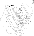
figure 4 is a perspective view on an enlarged scale of a detail ofFigure 3 ; -
figure 5 is a perspective view on a reduced scale of the support structure ofFigure 3 and of an actuator member of the molding device according to the present invention configured to interact with the support structure itself; -
figures 6 and 7 are side views on a reduced scale of the detail ofFigure 4 in different operating phases during the interaction with the actuator member ofFigure 5 ; and -
figures 8A, 8B and 8C are side views of further examples of parts in composite material with a thermoplastic matrix which can be produced by means of the molding device according to the dictates of the present invention. - In
Figures 1 and2 , 1 indicates as a whole an example of a compression molding device according to the present invention configured to produce a first example of a part orcomponent 2 in composite material, preferably for use in the aeronautical sector, starting from aplane plate 3 in composite material with a thermoplastic matrix, in particular having a matrix based on thermoplastic, semi-crystalline or amorphous resin. - In the first case, the semi-crystalline thermoplastic resin can be for example polyether-ether-ketone, or PEEK. Alternatively, said semi-crystalline thermoplastic resin can be for example polyether-ketone-ketone, or PEKK. An example of an amorphous thermoplastic resin is represented by polyetherimide, or PEI.
- The reinforcing fibres can be arranged in one or more unidirectional layers, in several layers having different orientations from each other or as a fabric.
- The reinforcing fibres are preferably made of carbon; alternatively, other types of reinforcing fibres known in the aeronautical sector can be used, such as for example glass fibres or a combination of glass and carbon fibres.
- It should be noted that the
starting plate 3 for carrying out the molding operation is a pre-consolidated plate, i.e. subjected in a known manner to a preliminary consolidation operation in a high-temperature press. - In the case illustrated, the
starting plate 3 for the production of thepart 2 in composite material has a plane rectangular conformation. - The
part 2 in composite material to be produced by molding starting from theplate 3 has (Figure 1 ) two lateral opposite, plane,horizontal portions 2a and arranged on the same lying plane, and acentral portion 2b having a substantially V-shaped profile, that is formed by two oblique sections converging towards each other into a common edge (i.e. the vertex of the V), preferably shaped like a plane horizontal strip, starting from the lateralopposite portions 2a. - In practice, the
part 2 has anupper surface 4, concave at thecentral portion 2b, and a lower surface 5, opposite theupper surface 4 and convex at thecentral portion 2b itself. - The molding device 1 comprises a
preheating station 6, for example an infrared ray oven, in which thepre-consolidated plate 3 is subjected to a heating operation so as to obtain the softening thereof, and amolding station 8, in which theplate 3 that is pre-consolidated and subsequently heated in thepreheating station 6 is subjected to a compression molding operation so as to obtain thepart 2. - The
molding station 8 essentially comprises: - a fixed support structure 9 (visible only partially in
figures 2 ,3 ,5 ,6 and 7 limitedly to the innovative part with respect to the known art); - an upper half-die 10 provided with a lower contoured
surface 11 corresponding to the profile of theupper surface 4 of thepart 2 in composite material to be made by molding; - a lower half-die 12 provided with an upper contoured
surface 13 corresponding to the profile of the lower surface 5 of thepart 2 in composite material to be made by molding; - holding means 15 carried by the
support structure 9 in a fixed position and configured to hold theplate 3 in a position interposed between the upper half-die 10 and the lower half-die 12; and - moving means, known per se and not illustrated, for moving one or both of the upper half-die 10 and lower half-die 12 from and towards the
plate 3 in a direction A transverse to theplate 3 itself. - In the case illustrated, the contoured
surface 11 of the upper half-die 10 has two lateral opposite, plane,horizontal sections 11a arranged on the same lying plane, and acentral section 11b defining a protuberance substantially having a V-shaped profile, i.e. formed by two oblique sections converging towards each other into a common edge (the vertex of the V), preferably shaped like a plane horizontal strip, starting from the oppositelateral sections 11a. - The contoured
surface 13 of the lower half-die 12 has a conformation complementary to that of the contouredsurface 11 of the upper half-die 10 and comprises two lateral opposite, plane,horizontal sections 13a arranged on the same lying plane, and acentral section 13b defining a cavity with substantially a V-shaped profile, i.e. formed by two oblique sections converging towards each other into a common edge (the vertex of the V), preferably shaped like a flat horizontal strip, starting from the lateralopposite sections 13a. - The
laterals sections lateral portions 2a of thepart 2, while thecentral sections central portion 2b of thepart 2 to be made by molding. - It is evident that the
part 2 illustrated herein is only an example of the possible parts or components in composite material that can be produced by means of the molding device according to the dictates of the present invention; as will be illustrated hereinafter, by simply varying the conformation of the contoured surfaces 11, 13 of the upper half-die 10 and lower half-die 12, it is possible to produce various shapes of parts in composite material. - Advantageously, the holding
elements 15 comprise respectivereleasable grippers 16 configured to grip by friction distinct portions of aperipheral edge 18 of theplate 3 and to completely release or allow the complete release of theplate 3 itself when the latter is compressed between the upper half-die 10 and the lower half-die 12 during the molding operation. - In practice, the
grippers 16 are configured to exert a retention force on theplate 3 less than the thrust received by theplate 3 itself in the direction of extraction from thegrippers 16 during compression between the upper half-die 10 and the lower half-die 12. - In this way, the
grippers 16 are configured to release theplate 3 and completely release theplate 3 in use, more precisely theperipheral edge 18 of theplate 3 itself, when the latter is compressed between the upper half-die 10 and the lower half-die 12 during the molding operation. - As illustrated in
Figures 2 ,3 and5 , thesupport structure 9 comprises aframe element 20, in this case with a rectangular profile, having a plurality ofattachment areas 21 for the selective fixing of a desired number ofgrippers 16 correlated to the configuration of theplate 3 to be molded and to the retention force on theplate 3 itself which is desired to be obtained. - In the case illustrated, two
grippers 16 are used, fixed on each of the two shorter sides of theframe element 20 and cooperating with lateral opposite portions of theperipheral edge 18 of theplate 3. - As is visible in
figures 2 ,3 ,5 ,6 and 7 , thegrippers 16 are fixed internally to theframe element 20 throughsupport arms 22 of variable or extensible length so as to be able to adapt to different profiles of the plate to be subjected to molding. - With reference to
figures 2 to 7 , eachgripper 16 comprises twojaws frame element 20 to which thegripper 16 itself is fixed, and which are movable between a closing configuration (Figures 4 and7 ) and an opening configuration (Figure 6 ). - In particular, in the opening configuration, the
jaws gripper 16 hold by friction the relative portion of theperipheral edge 18 of theplate 3; otherwise, in the opening configuration, thejaws gripper 16 are moved away from one another with respect to the closing configuration to allow the insertion or removal of theplate 3. - The hinging axes B of the
jaws gripper 16 are orthogonal to the direction A and parallel to the relative side of theperipheral edge 18 of theplate 3 on which they act. - With particular reference to the solution illustrated in
Figures 4 ,6 and 7 , thejaw 23 of eachgripper 16 is arranged below thejaw 24 and is fixed to therelative support arm 22 so as to project from the latter in the same direction of extension towards the inside of theframe element 20; thejaw 23 has a substantially flat frontoperative portion 25 extending from the hinging area with therelative jaw 24 and defining a support for the relative portion of theperipheral edge 18 of theplate 3. - The
jaw 24 of eachgripper 16 has a frontoperative portion 26, also extending from the hinging area with therelative jaw 23 and substantially V-shaped with concavity facing towards thejaw 23 itself so as to cooperate with therelative plate 3 along a line or strip of the latter. - The hinging area between the
jaws gripper 16 comprises apin 27 of axis B, one ormore arms 28 wound around thepin 27 and fixed to thejaw 23 and one ormore arms 29 also wound around thepin 27 and fixed tojaw 24. - Each
gripper 16 also comprises actuator means 30 configured to load one or both of therelative jaws relative plate 3. - In the case illustrated, the actuator means 30 of each
gripper 16 comprise aspring 31, in particular with a cylindrical helix, wound around therelative pin 27 and acting on thejaws respective arms same jaws - According to a possible alternative, not illustrated, the actuator means 30 could comprise a hydraulic or electric actuator with automatic adjustment of the closing force acting on the
jaws gripper 16. - Each
gripper 16 also comprises an actuatingportion 32 carried by one of thejaws relative operating portion - In the case illustrated, the actuating
portion 32 is constituted by a plate fixed, at its own end portion 32a, to thejaw 24 in proximity to the hinging area and protruding rearwardly in a cantilever manner from thejaw 24 itself. In greater detail, the actuatingportion 32 of eachgripper 16 extends posteriorly to thejaw 23 so as to spread apart therefrom starting from the hinging area and has a free end portion 32b, opposite the end portion 32a and slightly bent towards thejaw 23 itself. - With particular reference to
figures 5 ,6 and 7 , the molding device 1 also comprises further actuator means 33 acting on theactuating portions 32 of thegripper 16 to move thegrippers 16 themselves into the opening configurations. - In the case illustrated, the actuator means 33 comprise a
further frame element 34, preferably with a rectangular profile, displaceable from and towards theframe element 20 carrying thegrippers 16 and provided withpushers 35 to act simultaneously on theactuating portions 32 of thegrippers 16 themselves. - In particular, the
pushers 35 consist of preferably cylindrical elements protruding orthogonally in a cantilever manner from theframe element 34 parallel to the direction A, positioned at theactuating portions 32 of thegrippers 16 and adapted to act simultaneously on all theactuating portions 32 against the action of therespective springs 31 during the movement of theframe element 34 towards theframe element 20 in order to move thejaws 24 away from therespective jaws 23 and arrange thegrippers 16 into the opening configuration. - According to a possible alternative, not illustrated, the actuator means 33 could also comprise a plurality of actuator members, for example of the fluidic type, acting individually on the
actuating portions 32 of therespective grippers 16. -
Figures 8A, 8B and 8C illustrate other possible examples of parts or components in composite material, indicated respectively with thereferences 2', 2", 2"', which can be produced by means of the molding device according to the present invention starting from plates in composite with a thermoplastic matrix. It is clear that in order to obtain the parts 2', 2'', 2''' it is necessary to modify the conformation of the contoured surfaces 11, 13 of the half-dies 10, 12 and it could be required to start from plates with profiles and proportions other than those of theplate 3. - The part 2' of
figure 8A has a substantially S-contoured profile; thepart 2" offigure 8B instead has a substantially U-contoured profile; finally, the part 2''' offigure 8C has a substantially U-contoured profile with opposite flat lateral protrusions extending from the free ends of the U in directions that are opposite one another. - The operation of the molding device 1 is described below with reference to the production of a
single part 2 starting from a respectivepre-consolidated plate 3 having a flat rectangular conformation. - In particular, the
plate 3 is first of all subjected to a preliminary heating operation in the preheatingstation 6 in order to soften the material which constitutes it. - Subsequently, the
preheated plate 3 is brought into themolding station 8 and secured to thegrippers 16 in the desired position between the upper half-die 10 and lower half-die 12. More precisely, by lowering theframe element 34 along the direction A towards theframe element 20, thepushers 35 cooperate, by pushing, with theactuating portions 32 of thegrippers 16 fixed to theframe element 20 itself (figure 6 ). The actuatingportions 32 of thejaws 24 are simultaneously lowered towards therespective jaws 23 thus causing thejaws 24 to rotate around thepins 27 with respect to therelative jaws 23 until reaching the opening configuration. - In this condition, the
plate 3 is inserted with itsperipheral edge 18 resting on thefront portions 25 of thejaws 23; subsequently, by moving theframe element 34 upwards again, the actuatingportions 32 of thejaws 24 are left free, thus allowing thejaws 24 to rotate around thepins 27 until reaching the closing configuration (Figures 2 ,3 ,4 ,5 ,7 ). - Once the positioning of the
plate 3 on thesupport structure 9 in a position interposed between the upper half-die 10 and the lower half-die 12 is ended, it is possible to proceed with the actual molding operation by moving only one of the half-dies 10, 12 themselves or both of them towards theplate 3. - As soon as the
plate 3 is compressed between thecontoured surfaces plate 3 causes the complete release of theplate 3 itself from thegrippers 16. - After the opening of the half-dies 10, 12 it is possible to remove the
finished part 2. - From an examination of the characteristics of the molding device 1 made according to the dictates of the present invention, the advantages it allows to obtain are evident.
- In particular, thanks to the fact that the starting
plate 3 is clamped between thegrippers 16 directly on its peripheral edge and is subsequently released by thegrippers 16 themselves when it is compressed between the two half-dies 10, 12, thefinished part 2 no longer has fixing ears to be provided for initially and to be removed after the molding operation. This allows a drastic reduction of scraps both when the starting plate is cut out from the sheet of pre-consolidated composite material as it is not necessary to cut out the fixing ears and after molding as it is not necessary to remove material from the molded part. - Finally, it is clear that modifications and variations can be made to the molding device 1 described and illustrated herein without thereby departing from the scope of protection defined by the claims.
Claims (10)
- Compression molding device (1) configured for the production of a part (2, 2', 2", 2''') in composite material starting from a plate (3), in particular a plane plate, in composite with a thermoplastic matrix, said device (1) comprising:- a fixed support structure (9);- an upper half-die (10) provided with a first contoured surface (11) corresponding to the profile of an upper surface (4) of said part (2, 2', 2'', 2''') in composite material to be made by molding;- a lower half-die (12) provided with a second contoured surface (13) corresponding to the profile of a lower surface (5) of said part (2, 2', 2", 2''') in composite material to be made by molding;- holding means (15) carried by said support structure (9) in a fixed position and configured to hold said plate (3) in a position interposed between said upper half-die (10) and said lower half-die (12); and- moving means for moving at least one of said upper half-die (10) and lower (12) half-die from and towards said plate (3) in a direction (A) transverse to the plate (3) itself;characterized in that said holding means (15) comprise two or more releasable grippers (16) gripping by friction distinct portions of a peripheral edge (18) of said plate (3) and configured to completely release or allow the complete release of the plate (3) itself when the latter is compressed between the upper half-die (10) and the lower half-die (12) during molding.
- Device according to claim 1, wherein said grippers (16) are configured to exert a retention force on said plate (3) less than the thrust received by the plate (3) itself in the direction of extraction from said grippers (16) during compression between the upper half-die (10) and the lower half-die (12).
- Device according to claim 1 or 2, wherein said support structure (9) comprises a frame element (20) having a plurality of attachment areas (21) for the selective fixing of a desired number of grippers (16) correlated to the configuration of the plate (3) to be molded and to the retention force on the plate (3) itself which is desired to be obtained.
- Device according to claim 3, wherein said grippers (16) are fixed internally to said frame element (20) through support arms (22) of variable or extensible length.
- Device according to any one of claims 2 to 4, wherein each gripper (16) comprises two jaws (23, 24) hinged together and movable between a closing configuration, in which they hold by friction the relative portion of the peripheral edge (18) of said plate (3), and an opening configuration, in which they are moved away to allow the insertion or removal of said plate (3); each gripper (16) also comprising first actuator means (30), in particular elastic means (31), configured to load one or both of said jaws (23, 24) towards said closing configuration and defining said retention force on said plate (3).
- Device according to claim 5, wherein one (23) of said jaws (23, 24) of each said gripper (16) has a substantially flat front operative portion (25) defining a support for the relative portion of the peripheral edge (18) of said plate (3), and the other jaw (24) of said jaws (23, 24) of said gripper (16) has a substantially V-shaped front operating portion (26) with concavity facing towards said one (23) of said jaws (23, 24) so as to cooperate with the relative plate (3) along a line or strip thereof.
- Device according to claim 6, wherein said operative portions (25, 26) of said jaws (23, 24) of each said gripper (16) extend from a common hinging area (B) of the jaws (23, 24) themselves.
- Device according to claim 7, wherein each said gripper (16) comprises an actuating portion (32) carried by one of said jaws (24) and extending rearwardly from said hinging zone (B) with respect to the relative said operating portion (26); said device (1) further comprising second actuator means (33) acting on the actuating portions (32) of said grippers (16) to move the grippers (16) themselves into said opening configurations.
- Device according to claim 8, wherein said second actuator means (33) comprise a second frame element (34) displaceable from and towards the frame element (20) carrying the grippers (16) and provided with pushers (35) to act simultaneously on said actuating portions (32) of the grippers (16) themselves.
- Device according to any one of the preceding claims, further comprising heating means (6) for softening said plate (3) before subjecting it to the compression action between said upper half-die (10) and said lower half-die (12).
Applications Claiming Priority (1)
| Application Number | Priority Date | Filing Date | Title |
|---|---|---|---|
| IT102019000015509A IT201900015509A1 (en) | 2019-09-03 | 2019-09-03 | COMPRESSION MOLDING DEVICE FOR COMPOSITE MATERIAL PARTS STARTING FROM COMPOSITE SHEETS WITH THERMOPLASTIC MATRIX |
Publications (2)
| Publication Number | Publication Date |
|---|---|
| EP3789175A1 true EP3789175A1 (en) | 2021-03-10 |
| EP3789175B1 EP3789175B1 (en) | 2026-02-18 |
Family
ID=69158238
Family Applications (1)
| Application Number | Title | Priority Date | Filing Date |
|---|---|---|---|
| EP20194334.7A Active EP3789175B1 (en) | 2019-09-03 | 2020-09-03 | Compression moulding for producing thermoplastic composite materials |
Country Status (7)
| Country | Link |
|---|---|
| US (1) | US11845203B2 (en) |
| EP (1) | EP3789175B1 (en) |
| JP (1) | JP7767002B2 (en) |
| CN (1) | CN112440492B (en) |
| CA (1) | CA3092104A1 (en) |
| ES (1) | ES3063134T3 (en) |
| IT (1) | IT201900015509A1 (en) |
Families Citing this family (3)
| Publication number | Priority date | Publication date | Assignee | Title |
|---|---|---|---|---|
| CN113524546B (en) * | 2021-08-19 | 2025-11-07 | 柳州环球汽车内饰件有限公司 | Mold structure of automobile hat rack and production process of automobile hat rack |
| CN114935499B (en) * | 2022-03-30 | 2023-07-07 | 荣耀终端有限公司 | A clamping device and testing device |
| IT202400010618A1 (en) * | 2024-05-10 | 2025-11-10 | Leonardo Spa | GRIP SYSTEM FOR COMPRESSION MOULDING OF COMPOSITE MATERIAL SHEETS |
Citations (6)
| Publication number | Priority date | Publication date | Assignee | Title |
|---|---|---|---|---|
| US20130101694A1 (en) * | 2010-06-14 | 2013-04-25 | Bayerische Motoren Werke Aktiengesellschaft | Method and Forming Tool for Producing a Fiber Composite Preform |
| US20140166417A1 (en) * | 2004-06-18 | 2014-06-19 | Samsonite Ip Holdings S.A R.L. | Process for making a luggage shell from self-reinforced thermo-plastic material |
| EP2875931A1 (en) * | 2013-10-16 | 2015-05-27 | C.M.S. S.p.A. | Method for forming a sheet of reinforced thermoplastic material |
| US20150258743A1 (en) * | 2012-10-25 | 2015-09-17 | Valeo Systemes Thermiques | Method for molding a composite material wherein a fiber fabric is tightened in a retention frame before injection of a matrix |
| JP2016043507A (en) * | 2014-08-20 | 2016-04-04 | 三菱レイヨン株式会社 | Preform manufacturing method and fiber reinforced composite material molded product manufacturing method |
| EP3473397A1 (en) * | 2017-10-23 | 2019-04-24 | Aleda SA | Assembly, system and method for making a preformed shell |
Family Cites Families (9)
| Publication number | Priority date | Publication date | Assignee | Title |
|---|---|---|---|---|
| US7618572B2 (en) * | 2005-08-12 | 2009-11-17 | Illinois Tool Works Inc. | Method and apparatus for manufacturing load bearing fabric support structures |
| CA2593519A1 (en) * | 2006-07-14 | 2009-01-12 | Marquez Transtech Ltee | Novel thermoplastic part, tool and method for the manufacturing thereof |
| JP4470190B2 (en) | 2007-10-23 | 2010-06-02 | 新東工業株式会社 | Material clamping method and material clamping device used in the method |
| US9448045B2 (en) * | 2010-11-16 | 2016-09-20 | Aldila Golf Corp. | High straightness arrow and method of manufacture |
| FR3020780B1 (en) * | 2014-05-09 | 2017-01-13 | Airbus Operations Sas | PROCESS FOR MANUFACTURING A COMPOSITE MATERIAL PART FOR AIRCRAFT STRUCTURE BY PULTRUSION AND COCUISSON |
| EP3426454B1 (en) * | 2016-03-10 | 2022-04-27 | GAVAZZI TESSUTI TECNICI S.p.A. | Method for forming a shell body and shell type body obtained with such a method |
| KR20180068364A (en) * | 2016-12-13 | 2018-06-22 | 현대자동차주식회사 | Apparatus for producing preforms of fibre composite |
| JP6821417B2 (en) * | 2016-12-16 | 2021-01-27 | 芝浦機械株式会社 | Transfer device and transfer head |
| DE202018006057U1 (en) * | 2018-12-11 | 2019-01-31 | Olbrich Gmbh | Mold for joining trim parts with flat decorative materials |
-
2019
- 2019-09-03 IT IT102019000015509A patent/IT201900015509A1/en unknown
-
2020
- 2020-09-01 CA CA3092104A patent/CA3092104A1/en active Pending
- 2020-09-01 JP JP2020146978A patent/JP7767002B2/en active Active
- 2020-09-02 US US17/010,024 patent/US11845203B2/en active Active
- 2020-09-03 ES ES20194334T patent/ES3063134T3/en active Active
- 2020-09-03 CN CN202010915252.2A patent/CN112440492B/en active Active
- 2020-09-03 EP EP20194334.7A patent/EP3789175B1/en active Active
Patent Citations (6)
| Publication number | Priority date | Publication date | Assignee | Title |
|---|---|---|---|---|
| US20140166417A1 (en) * | 2004-06-18 | 2014-06-19 | Samsonite Ip Holdings S.A R.L. | Process for making a luggage shell from self-reinforced thermo-plastic material |
| US20130101694A1 (en) * | 2010-06-14 | 2013-04-25 | Bayerische Motoren Werke Aktiengesellschaft | Method and Forming Tool for Producing a Fiber Composite Preform |
| US20150258743A1 (en) * | 2012-10-25 | 2015-09-17 | Valeo Systemes Thermiques | Method for molding a composite material wherein a fiber fabric is tightened in a retention frame before injection of a matrix |
| EP2875931A1 (en) * | 2013-10-16 | 2015-05-27 | C.M.S. S.p.A. | Method for forming a sheet of reinforced thermoplastic material |
| JP2016043507A (en) * | 2014-08-20 | 2016-04-04 | 三菱レイヨン株式会社 | Preform manufacturing method and fiber reinforced composite material molded product manufacturing method |
| EP3473397A1 (en) * | 2017-10-23 | 2019-04-24 | Aleda SA | Assembly, system and method for making a preformed shell |
Also Published As
| Publication number | Publication date |
|---|---|
| CA3092104A1 (en) | 2021-03-03 |
| US20210060831A1 (en) | 2021-03-04 |
| JP7767002B2 (en) | 2025-11-11 |
| CN112440492B (en) | 2024-08-16 |
| EP3789175B1 (en) | 2026-02-18 |
| JP2021045962A (en) | 2021-03-25 |
| CN112440492A (en) | 2021-03-05 |
| IT201900015509A1 (en) | 2021-03-03 |
| US11845203B2 (en) | 2023-12-19 |
| RU2020129003A (en) | 2022-03-02 |
| ES3063134T3 (en) | 2026-04-15 |
| BR102020017800A2 (en) | 2021-03-30 |
Similar Documents
| Publication | Publication Date | Title |
|---|---|---|
| EP3789175B1 (en) | Compression moulding for producing thermoplastic composite materials | |
| EP0341865B1 (en) | Method of shaping blanks of thermoformable material | |
| RU2508199C2 (en) | Method of semi-finished product fabrication from esm laminate with two prepreg layers and process unit to this end | |
| JP6543791B2 (en) | Method of manufacturing resin molded body and press molding apparatus | |
| JP6048730B2 (en) | Preform manufacturing method | |
| EP2875931B1 (en) | Method for forming a sheet of reinforced thermoplastic material | |
| CA2021493A1 (en) | Method of forming thermoformable composite material | |
| CN113939396A (en) | Apparatus for producing molded article of fiber-reinforced resin material and method for producing molded article | |
| US12508785B2 (en) | Composite part production system | |
| EP4647229A1 (en) | Gripping system for compression molding of slabs of composite material | |
| CN108501403B (en) | Method for producing a shaped part | |
| JP2023510605A (en) | Automated mechanical forming of composites | |
| CN113891794A (en) | Apparatus for producing molded article of fiber-reinforced resin material and method for producing molded article | |
| EP4714641A1 (en) | Method and device for the transfer and stamping of a thermoplastic composite blank | |
| RU2817364C2 (en) | Device for compression molding of parts from composite material based on plates from composite material with thermoplastic matrix | |
| JP7824076B2 (en) | Mechanical forming of composite materials | |
| CA2593519A1 (en) | Novel thermoplastic part, tool and method for the manufacturing thereof | |
| JP5546049B2 (en) | Peeling jig and peeling method | |
| EP4096906B1 (en) | Thermoplastic composite having one or more inner openings and method for moulding said composite | |
| BR102020017800B1 (en) | COMPRESSION MOLDING DEVICE | |
| US11724468B2 (en) | Method and device for manufacturing a profile member of composite material, the cross-section of which has three branches | |
| KR102207477B1 (en) | Apparatus for making the preform | |
| JP2017177387A (en) | Apparatus and method for producing fiber-reinforced plastic | |
| JP2016165856A (en) | Fiber reinforced plastic manufacturing apparatus and manufacturing method | |
| GB2561334A (en) | A Moveable positioning device for a forming press |
Legal Events
| Date | Code | Title | Description |
|---|---|---|---|
| PUAI | Public reference made under article 153(3) epc to a published international application that has entered the european phase |
Free format text: ORIGINAL CODE: 0009012 |
|
| STAA | Information on the status of an ep patent application or granted ep patent |
Free format text: STATUS: THE APPLICATION HAS BEEN PUBLISHED |
|
| AK | Designated contracting states |
Kind code of ref document: A1 Designated state(s): AL AT BE BG CH CY CZ DE DK EE ES FI FR GB GR HR HU IE IS IT LI LT LU LV MC MK MT NL NO PL PT RO RS SE SI SK SM TR |
|
| AX | Request for extension of the european patent |
Extension state: BA ME |
|
| STAA | Information on the status of an ep patent application or granted ep patent |
Free format text: STATUS: REQUEST FOR EXAMINATION WAS MADE |
|
| 17P | Request for examination filed |
Effective date: 20210603 |
|
| RBV | Designated contracting states (corrected) |
Designated state(s): AL AT BE BG CH CY CZ DE DK EE ES FI FR GB GR HR HU IE IS IT LI LT LU LV MC MK MT NL NO PL PT RO RS SE SI SK SM TR |
|
| RIC1 | Information provided on ipc code assigned before grant |
Ipc: B29K 105/08 20060101ALN20220201BHEP Ipc: B29C 70/46 20060101ALN20220201BHEP Ipc: B29L 31/30 20060101ALN20220201BHEP Ipc: B29K 101/12 20060101ALN20220201BHEP Ipc: B29C 70/56 20060101ALI20220201BHEP Ipc: B29C 70/54 20060101ALI20220201BHEP Ipc: B29C 43/36 20060101AFI20220201BHEP |
|
| STAA | Information on the status of an ep patent application or granted ep patent |
Free format text: STATUS: EXAMINATION IS IN PROGRESS |
|
| 17Q | First examination report despatched |
Effective date: 20220323 |
|
| GRAP | Despatch of communication of intention to grant a patent |
Free format text: ORIGINAL CODE: EPIDOSNIGR1 |
|
| STAA | Information on the status of an ep patent application or granted ep patent |
Free format text: STATUS: GRANT OF PATENT IS INTENDED |
|
| RIC1 | Information provided on ipc code assigned before grant |
Ipc: B29C 43/36 20060101AFI20250708BHEP Ipc: B29C 70/54 20060101ALI20250708BHEP Ipc: B29C 70/56 20060101ALI20250708BHEP Ipc: B29K 101/12 20060101ALN20250708BHEP Ipc: B29L 31/30 20060101ALN20250708BHEP Ipc: B29C 70/46 20060101ALN20250708BHEP Ipc: B29K 105/08 20060101ALN20250708BHEP |
|
| RIC1 | Information provided on ipc code assigned before grant |
Ipc: B29C 43/36 20060101AFI20250806BHEP Ipc: B29C 70/54 20060101ALI20250806BHEP Ipc: B29C 70/56 20060101ALI20250806BHEP Ipc: B29K 101/12 20060101ALN20250806BHEP Ipc: B29L 31/30 20060101ALN20250806BHEP Ipc: B29C 70/46 20060101ALN20250806BHEP Ipc: B29K 105/08 20060101ALN20250806BHEP |
|
| INTG | Intention to grant announced |
Effective date: 20250813 |
|
| P01 | Opt-out of the competence of the unified patent court (upc) registered |
Free format text: CASE NUMBER: UPC_APP_0013898_3789175/2025 Effective date: 20251119 |
|
| GRAS | Grant fee paid |
Free format text: ORIGINAL CODE: EPIDOSNIGR3 |
|
| GRAA | (expected) grant |
Free format text: ORIGINAL CODE: 0009210 |
|
| STAA | Information on the status of an ep patent application or granted ep patent |
Free format text: STATUS: THE PATENT HAS BEEN GRANTED |
|
| AK | Designated contracting states |
Kind code of ref document: B1 Designated state(s): AL AT BE BG CH CY CZ DE DK EE ES FI FR GB GR HR HU IE IS IT LI LT LU LV MC MK MT NL NO PL PT RO RS SE SI SK SM TR |
|
| REG | Reference to a national code |
Ref country code: CH Ref legal event code: F10 Free format text: ST27 STATUS EVENT CODE: U-0-0-F10-F00 (AS PROVIDED BY THE NATIONAL OFFICE) Effective date: 20260218 Ref country code: GB Ref legal event code: FG4D |
|
| REG | Reference to a national code |
Ref country code: DE Ref legal event code: R096 Ref document number: 602020066986 Country of ref document: DE |
|
| REG | Reference to a national code |
Ref country code: IE Ref legal event code: FG4D |
|
| REG | Reference to a national code |
Ref country code: ES Ref legal event code: FG2A Ref document number: 3063134 Country of ref document: ES Kind code of ref document: T3 Effective date: 20260415 |
|
| REG | Reference to a national code |
Ref country code: NL Ref legal event code: MP Effective date: 20260218 |
|
| PG25 | Lapsed in a contracting state [announced via postgrant information from national office to epo] |
Ref country code: RS Free format text: LAPSE BECAUSE OF FAILURE TO SUBMIT A TRANSLATION OF THE DESCRIPTION OR TO PAY THE FEE WITHIN THE PRESCRIBED TIME-LIMIT Effective date: 20260518 |
|
| PG25 | Lapsed in a contracting state [announced via postgrant information from national office to epo] |
Ref country code: PL Free format text: LAPSE BECAUSE OF FAILURE TO SUBMIT A TRANSLATION OF THE DESCRIPTION OR TO PAY THE FEE WITHIN THE PRESCRIBED TIME-LIMIT Effective date: 20260218 |
|
| PG25 | Lapsed in a contracting state [announced via postgrant information from national office to epo] |
Ref country code: GR Free format text: LAPSE BECAUSE OF FAILURE TO SUBMIT A TRANSLATION OF THE DESCRIPTION OR TO PAY THE FEE WITHIN THE PRESCRIBED TIME-LIMIT Effective date: 20260519 |
|
| REG | Reference to a national code |
Ref country code: LT Ref legal event code: MG9D |
|
| PG25 | Lapsed in a contracting state [announced via postgrant information from national office to epo] |
Ref country code: LT Free format text: LAPSE BECAUSE OF FAILURE TO SUBMIT A TRANSLATION OF THE DESCRIPTION OR TO PAY THE FEE WITHIN THE PRESCRIBED TIME-LIMIT Effective date: 20260218 |
|
| PG25 | Lapsed in a contracting state [announced via postgrant information from national office to epo] |
Ref country code: NO Free format text: LAPSE BECAUSE OF FAILURE TO SUBMIT A TRANSLATION OF THE DESCRIPTION OR TO PAY THE FEE WITHIN THE PRESCRIBED TIME-LIMIT Effective date: 20260518 |
|
| PG25 | Lapsed in a contracting state [announced via postgrant information from national office to epo] |
Ref country code: FI Free format text: LAPSE BECAUSE OF FAILURE TO SUBMIT A TRANSLATION OF THE DESCRIPTION OR TO PAY THE FEE WITHIN THE PRESCRIBED TIME-LIMIT Effective date: 20260218 Ref country code: AT Free format text: LAPSE BECAUSE OF FAILURE TO SUBMIT A TRANSLATION OF THE DESCRIPTION OR TO PAY THE FEE WITHIN THE PRESCRIBED TIME-LIMIT Effective date: 20260218 Ref country code: SE Free format text: LAPSE BECAUSE OF FAILURE TO SUBMIT A TRANSLATION OF THE DESCRIPTION OR TO PAY THE FEE WITHIN THE PRESCRIBED TIME-LIMIT Effective date: 20260218 |
|
| REG | Reference to a national code |
Ref country code: AT Ref legal event code: MK05 Ref document number: 1887631 Country of ref document: AT Kind code of ref document: T Effective date: 20260218 |
|
| PG25 | Lapsed in a contracting state [announced via postgrant information from national office to epo] |
Ref country code: HR Free format text: LAPSE BECAUSE OF FAILURE TO SUBMIT A TRANSLATION OF THE DESCRIPTION OR TO PAY THE FEE WITHIN THE PRESCRIBED TIME-LIMIT Effective date: 20260218 |
|
| PG25 | Lapsed in a contracting state [announced via postgrant information from national office to epo] |
Ref country code: IS Free format text: LAPSE BECAUSE OF FAILURE TO SUBMIT A TRANSLATION OF THE DESCRIPTION OR TO PAY THE FEE WITHIN THE PRESCRIBED TIME-LIMIT Effective date: 20260618 Ref country code: PT Free format text: LAPSE BECAUSE OF FAILURE TO SUBMIT A TRANSLATION OF THE DESCRIPTION OR TO PAY THE FEE WITHIN THE PRESCRIBED TIME-LIMIT Effective date: 20260618 |
|
| PG25 | Lapsed in a contracting state [announced via postgrant information from national office to epo] |
Ref country code: NL Free format text: LAPSE BECAUSE OF FAILURE TO SUBMIT A TRANSLATION OF THE DESCRIPTION OR TO PAY THE FEE WITHIN THE PRESCRIBED TIME-LIMIT Effective date: 20260218 |
|
| PG25 | Lapsed in a contracting state [announced via postgrant information from national office to epo] |
Ref country code: LV Free format text: LAPSE BECAUSE OF FAILURE TO SUBMIT A TRANSLATION OF THE DESCRIPTION OR TO PAY THE FEE WITHIN THE PRESCRIBED TIME-LIMIT Effective date: 20260218 |
|
| PG25 | Lapsed in a contracting state [announced via postgrant information from national office to epo] |
Ref country code: BG Free format text: LAPSE BECAUSE OF FAILURE TO SUBMIT A TRANSLATION OF THE DESCRIPTION OR TO PAY THE FEE WITHIN THE PRESCRIBED TIME-LIMIT Effective date: 20260218 |