EP3789136A1 - Additive manufacturing machine - Google Patents
Additive manufacturing machine Download PDFInfo
- Publication number
- EP3789136A1 EP3789136A1 EP20194848.6A EP20194848A EP3789136A1 EP 3789136 A1 EP3789136 A1 EP 3789136A1 EP 20194848 A EP20194848 A EP 20194848A EP 3789136 A1 EP3789136 A1 EP 3789136A1
- Authority
- EP
- European Patent Office
- Prior art keywords
- support
- additive manufacturing
- manufacturing machine
- arm portion
- box
- Prior art date
- Legal status (The legal status is an assumption and is not a legal conclusion. Google has not performed a legal analysis and makes no representation as to the accuracy of the status listed.)
- Granted
Links
Images





Classifications
-
- B—PERFORMING OPERATIONS; TRANSPORTING
- B29—WORKING OF PLASTICS; WORKING OF SUBSTANCES IN A PLASTIC STATE IN GENERAL
- B29C—SHAPING OR JOINING OF PLASTICS; SHAPING OF MATERIAL IN A PLASTIC STATE, NOT OTHERWISE PROVIDED FOR; AFTER-TREATMENT OF THE SHAPED PRODUCTS, e.g. REPAIRING
- B29C64/00—Additive manufacturing, i.e. manufacturing of three-dimensional [3D] objects by additive deposition, additive agglomeration or additive layering, e.g. by 3D printing, stereolithography or selective laser sintering
- B29C64/20—Apparatus for additive manufacturing; Details thereof or accessories therefor
- B29C64/205—Means for applying layers
- B29C64/218—Rollers
-
- B—PERFORMING OPERATIONS; TRANSPORTING
- B22—CASTING; POWDER METALLURGY
- B22F—WORKING METALLIC POWDER; MANUFACTURE OF ARTICLES FROM METALLIC POWDER; MAKING METALLIC POWDER; APPARATUS OR DEVICES SPECIALLY ADAPTED FOR METALLIC POWDER
- B22F10/00—Additive manufacturing of workpieces or articles from metallic powder
- B22F10/20—Direct sintering or melting
- B22F10/28—Powder bed fusion, e.g. selective laser melting [SLM] or electron beam melting [EBM]
-
- B—PERFORMING OPERATIONS; TRANSPORTING
- B22—CASTING; POWDER METALLURGY
- B22F—WORKING METALLIC POWDER; MANUFACTURE OF ARTICLES FROM METALLIC POWDER; MAKING METALLIC POWDER; APPARATUS OR DEVICES SPECIALLY ADAPTED FOR METALLIC POWDER
- B22F12/00—Apparatus or devices specially adapted for additive manufacturing; Auxiliary means for additive manufacturing; Combinations of additive manufacturing apparatus or devices with other processing apparatus or devices
- B22F12/22—Driving means
- B22F12/224—Driving means for motion along a direction within the plane of a layer
-
- B—PERFORMING OPERATIONS; TRANSPORTING
- B22—CASTING; POWDER METALLURGY
- B22F—WORKING METALLIC POWDER; MANUFACTURE OF ARTICLES FROM METALLIC POWDER; MAKING METALLIC POWDER; APPARATUS OR DEVICES SPECIALLY ADAPTED FOR METALLIC POWDER
- B22F12/00—Apparatus or devices specially adapted for additive manufacturing; Auxiliary means for additive manufacturing; Combinations of additive manufacturing apparatus or devices with other processing apparatus or devices
- B22F12/50—Means for feeding of material, e.g. heads
-
- B—PERFORMING OPERATIONS; TRANSPORTING
- B22—CASTING; POWDER METALLURGY
- B22F—WORKING METALLIC POWDER; MANUFACTURE OF ARTICLES FROM METALLIC POWDER; MAKING METALLIC POWDER; APPARATUS OR DEVICES SPECIALLY ADAPTED FOR METALLIC POWDER
- B22F12/00—Apparatus or devices specially adapted for additive manufacturing; Auxiliary means for additive manufacturing; Combinations of additive manufacturing apparatus or devices with other processing apparatus or devices
- B22F12/60—Planarisation devices; Compression devices
-
- B—PERFORMING OPERATIONS; TRANSPORTING
- B29—WORKING OF PLASTICS; WORKING OF SUBSTANCES IN A PLASTIC STATE IN GENERAL
- B29C—SHAPING OR JOINING OF PLASTICS; SHAPING OF MATERIAL IN A PLASTIC STATE, NOT OTHERWISE PROVIDED FOR; AFTER-TREATMENT OF THE SHAPED PRODUCTS, e.g. REPAIRING
- B29C64/00—Additive manufacturing, i.e. manufacturing of three-dimensional [3D] objects by additive deposition, additive agglomeration or additive layering, e.g. by 3D printing, stereolithography or selective laser sintering
- B29C64/10—Processes of additive manufacturing
- B29C64/141—Processes of additive manufacturing using only solid materials
- B29C64/153—Processes of additive manufacturing using only solid materials using layers of powder being selectively joined, e.g. by selective laser sintering or melting
-
- B—PERFORMING OPERATIONS; TRANSPORTING
- B29—WORKING OF PLASTICS; WORKING OF SUBSTANCES IN A PLASTIC STATE IN GENERAL
- B29C—SHAPING OR JOINING OF PLASTICS; SHAPING OF MATERIAL IN A PLASTIC STATE, NOT OTHERWISE PROVIDED FOR; AFTER-TREATMENT OF THE SHAPED PRODUCTS, e.g. REPAIRING
- B29C64/00—Additive manufacturing, i.e. manufacturing of three-dimensional [3D] objects by additive deposition, additive agglomeration or additive layering, e.g. by 3D printing, stereolithography or selective laser sintering
- B29C64/20—Apparatus for additive manufacturing; Details thereof or accessories therefor
- B29C64/205—Means for applying layers
-
- B—PERFORMING OPERATIONS; TRANSPORTING
- B29—WORKING OF PLASTICS; WORKING OF SUBSTANCES IN A PLASTIC STATE IN GENERAL
- B29C—SHAPING OR JOINING OF PLASTICS; SHAPING OF MATERIAL IN A PLASTIC STATE, NOT OTHERWISE PROVIDED FOR; AFTER-TREATMENT OF THE SHAPED PRODUCTS, e.g. REPAIRING
- B29C64/00—Additive manufacturing, i.e. manufacturing of three-dimensional [3D] objects by additive deposition, additive agglomeration or additive layering, e.g. by 3D printing, stereolithography or selective laser sintering
- B29C64/20—Apparatus for additive manufacturing; Details thereof or accessories therefor
- B29C64/227—Driving means
- B29C64/232—Driving means for motion along the axis orthogonal to the plane of a layer
-
- B—PERFORMING OPERATIONS; TRANSPORTING
- B29—WORKING OF PLASTICS; WORKING OF SUBSTANCES IN A PLASTIC STATE IN GENERAL
- B29C—SHAPING OR JOINING OF PLASTICS; SHAPING OF MATERIAL IN A PLASTIC STATE, NOT OTHERWISE PROVIDED FOR; AFTER-TREATMENT OF THE SHAPED PRODUCTS, e.g. REPAIRING
- B29C64/00—Additive manufacturing, i.e. manufacturing of three-dimensional [3D] objects by additive deposition, additive agglomeration or additive layering, e.g. by 3D printing, stereolithography or selective laser sintering
- B29C64/20—Apparatus for additive manufacturing; Details thereof or accessories therefor
- B29C64/245—Platforms or substrates
-
- B—PERFORMING OPERATIONS; TRANSPORTING
- B29—WORKING OF PLASTICS; WORKING OF SUBSTANCES IN A PLASTIC STATE IN GENERAL
- B29C—SHAPING OR JOINING OF PLASTICS; SHAPING OF MATERIAL IN A PLASTIC STATE, NOT OTHERWISE PROVIDED FOR; AFTER-TREATMENT OF THE SHAPED PRODUCTS, e.g. REPAIRING
- B29C64/00—Additive manufacturing, i.e. manufacturing of three-dimensional [3D] objects by additive deposition, additive agglomeration or additive layering, e.g. by 3D printing, stereolithography or selective laser sintering
- B29C64/30—Auxiliary operations or equipment
- B29C64/307—Handling of material to be used in additive manufacturing
- B29C64/321—Feeding
-
- B—PERFORMING OPERATIONS; TRANSPORTING
- B22—CASTING; POWDER METALLURGY
- B22F—WORKING METALLIC POWDER; MANUFACTURE OF ARTICLES FROM METALLIC POWDER; MAKING METALLIC POWDER; APPARATUS OR DEVICES SPECIALLY ADAPTED FOR METALLIC POWDER
- B22F12/00—Apparatus or devices specially adapted for additive manufacturing; Auxiliary means for additive manufacturing; Combinations of additive manufacturing apparatus or devices with other processing apparatus or devices
- B22F12/40—Radiation means
- B22F12/41—Radiation means characterised by the type, e.g. laser or electron beam
-
- B—PERFORMING OPERATIONS; TRANSPORTING
- B22—CASTING; POWDER METALLURGY
- B22F—WORKING METALLIC POWDER; MANUFACTURE OF ARTICLES FROM METALLIC POWDER; MAKING METALLIC POWDER; APPARATUS OR DEVICES SPECIALLY ADAPTED FOR METALLIC POWDER
- B22F12/00—Apparatus or devices specially adapted for additive manufacturing; Auxiliary means for additive manufacturing; Combinations of additive manufacturing apparatus or devices with other processing apparatus or devices
- B22F12/50—Means for feeding of material, e.g. heads
- B22F12/52—Hoppers
-
- B—PERFORMING OPERATIONS; TRANSPORTING
- B22—CASTING; POWDER METALLURGY
- B22F—WORKING METALLIC POWDER; MANUFACTURE OF ARTICLES FROM METALLIC POWDER; MAKING METALLIC POWDER; APPARATUS OR DEVICES SPECIALLY ADAPTED FOR METALLIC POWDER
- B22F12/00—Apparatus or devices specially adapted for additive manufacturing; Auxiliary means for additive manufacturing; Combinations of additive manufacturing apparatus or devices with other processing apparatus or devices
- B22F12/60—Planarisation devices; Compression devices
- B22F12/67—Blades
-
- B—PERFORMING OPERATIONS; TRANSPORTING
- B22—CASTING; POWDER METALLURGY
- B22F—WORKING METALLIC POWDER; MANUFACTURE OF ARTICLES FROM METALLIC POWDER; MAKING METALLIC POWDER; APPARATUS OR DEVICES SPECIALLY ADAPTED FOR METALLIC POWDER
- B22F2999/00—Aspects linked to processes or compositions used in powder metallurgy
-
- B—PERFORMING OPERATIONS; TRANSPORTING
- B33—ADDITIVE MANUFACTURING TECHNOLOGY
- B33Y—ADDITIVE MANUFACTURING, i.e. MANUFACTURING OF THREE-DIMENSIONAL [3D] OBJECTS BY ADDITIVE DEPOSITION, ADDITIVE AGGLOMERATION OR ADDITIVE LAYERING, e.g. BY 3D PRINTING, STEREOLITHOGRAPHY OR SELECTIVE LASER SINTERING
- B33Y30/00—Apparatus for additive manufacturing; Details thereof or accessories therefor
-
- Y—GENERAL TAGGING OF NEW TECHNOLOGICAL DEVELOPMENTS; GENERAL TAGGING OF CROSS-SECTIONAL TECHNOLOGIES SPANNING OVER SEVERAL SECTIONS OF THE IPC; TECHNICAL SUBJECTS COVERED BY FORMER USPC CROSS-REFERENCE ART COLLECTIONS [XRACs] AND DIGESTS
- Y02—TECHNOLOGIES OR APPLICATIONS FOR MITIGATION OR ADAPTATION AGAINST CLIMATE CHANGE
- Y02P—CLIMATE CHANGE MITIGATION TECHNOLOGIES IN THE PRODUCTION OR PROCESSING OF GOODS
- Y02P10/00—Technologies related to metal processing
- Y02P10/25—Process efficiency
Definitions
- the present invention relates to an additive manufacturing machine for manufacturing a three-dimensional object by successively stacking thin layers of a powdered material on a support stage.
- additive manufacturing for manufacturing a three-dimensional (3D) object on a layer-by-layer basis by laying down a powdered material as stacked thin layers has attracted attention.
- Various types of additive manufacturing techniques have been developed utilizing different powdered materials and different 3D object fabrication techniques.
- One known method of additive manufacturing starts with laying down a powdered material, for example, as stacked layers on the top surface of a powder support stage on a layer-by-layer basis. Then, only a two-dimensional structure portion of the layers of the powdered material over the stage which corresponds to one cross section through a 3D object to be built is molten by a heating mechanism consisting of an electron beam or laser beam. Such molten layers of the powdered material are stacked successively in the heightwise direction (z-direction) to thereby create the 3D object (see, for example, Patent document 1)
- Patent document 1 sets forth that a powder feeder makes sliding movement, i.e., moves over a manufacturing box, to thereby smooth out powdered material and that a layer of the powder is consequently formed on the support stage.
- Patent document 1 JP-A-2019-7072
- Patent document 1 suffers from the problem that vibrations of the mechanical drive portion is transmitted to the smoothing plate, whereby the powdered material cannot be smoothed out.
- the present invention has been made. It is an object of the present invention to provide an additive manufacturing machine which has a smoothing plate and a manufacturing box and which is capable of smoothing out a powdered material while preventing mechanical interference between the smoothing plate and the manufacturing box.
- An additive manufacturing machine which achieves the above-described object in accordance with the teachings of the present invention has a support stage, a manufacturing box, and a powder feeder mechanism.
- a powdered material for manufacturing a three-dimensional (3D) object is stacked as a series of layers on the support stage.
- the manufacturing box has a cylindrical portion on which the support stage is slidably disposed.
- the powder feeder mechanism feeds the powdered material onto the support stage and smooths out the powdered material.
- the powder feeder mechanism has an arm portion, a guide mechanism, a connective portion, and a drive mechanism.
- a smoothing plate for smoothing out the powdered material is fixedly secured to the arm portion.
- the guide mechanism is secured to the manufacturing box and supports the arm portion such that the arm portion can move in a first direction that is parallel to one surface of the support stage which defines a working surface.
- the connective portion is connected to the arm portion and transmits mechanical force to the arm portion only in the first direction.
- the drive mechanism is secured to a support member different from the manufacturing box and has a drive portion for moving the connective portion in the first direction.
- the powdered material can be smoothed out while preventing mechanical interference between the smoothing plate and the manufacturing box.
- FIGS. 1 to 18 The preferred embodiments of the additive manufacturing machine of the present invention are hereinafter described with reference to FIGS. 1 to 18 .
- like components are indicated by like reference numerals.
- FIG. 1 is a schematic cross-sectional view of the additive manufacturing machine.
- the additive manufacturing machine shown in FIG. 1 is generally indicated by reference numeral 1 and operates to build a three-dimensional object by irradiating a powdered material such as a powdered metal (e.g., titanium, aluminum, or iron) with an electron beam to melt the material, and stacking layers of the solidified powdered material on top of each other.
- a powdered material such as a powdered metal (e.g., titanium, aluminum, or iron) with an electron beam to melt the material, and stacking layers of the solidified powdered material on top of each other.
- the additive manufacturing machine 1 has a hollow processing chamber 2, a manufacturing box 3, a support stage 4 in the form of a flat plate, a stage drive mechanism 5, a support base 6, a powder feeder mechanism 7, an electron gun 8, and powder tanks or reservoirs 9. It is assumed that the support stage 4 has one surface (working surface) 4a parallel to a first direction X and that a second direction Y is perpendicular to the first direction X and parallel to the working surface 4a of the stage 4. It is also assumed that a direction perpendicular to the working surface 4a of the support stage 4 is a third direction Z.
- a vacuum pump (not shown) is connected to the processing chamber 2.
- the air inside the processing chamber 2 is evacuated by the vacuum pump and so the inside of the processing chamber 2 is maintained as a vacuum.
- the manufacturing box 3, support stage 4, stage drive mechanism 5, support base 6, powder feeder mechanism 7, and powder reservoirs 9 are arranged inside the processing chamber 2.
- the electron gun 8 is mounted to the front end of the processing chamber 2 as viewed in the third direction Z, i.e., at the top of the processing chamber 2.
- the manufacturing box 3 is supported on the support base 6 and placed at a position opposite to the electron gun 8 in the third direction Z.
- the manufacturing box 3 has a cylindrical portion 3a and a flange portion 3b representing a reference plate.
- the axial direction of the cylindrical portion 3a is parallel to the third direction Z.
- the cylindrical portion 3a has open opposite end portions in the third direction Z.
- a powdered material M1 fed by the powder feeder mechanism 7 (described later) and a three-dimensional object built from the material M1 are accommodated in the hollow interior of the cylindrical portion 3a.
- the flange portion 3b is formed at the outer fringes of the upper end of the cylindrical portion 3a that is at the front end in the third direction Z.
- the flange portion 3b is bent substantially vertically from the outer fringes of the cylindrical portion 3a.
- the flange portion 3b is placed parallel to the first direction X and to the second direction Y.
- a fringe portion 3c (see FIG. 2 ) is formed at the outer fringes of the flange portion 3b and protrudes in the positive third direction Z.
- the flange portion 3b is supported on the support base 6 that is disposed inside the processing chamber 2. Therefore, the axial front end of the cylindical portion 3a of the manufacturing box 3, i.e., upper end, is a fixed end, while the axial rear end of the cylindrical portion 3a, i.e., lower end, is a free end.
- the structure of the manufacturing box 3 and the structure of the support base 6 that supports the manufacturing box 3 are described in detail later.
- the powder reservoirs 9 for storing the powdered material M1 are disposed at opposite ends of the flange portion 3b in the first direction X. Also, the powder reservoirs 9 are disposed over the front end of the flange portion 3b in the third direction Z, i.e., above the flange portion 3b.
- a volumetric feeder for dispensing a given amount of powdered material M1 is arranged on the side of a respective one of the powder reservoirs 9 which is opposite to the flange portion 3b. Each volumetric feeder feeds a given amount of powdered material M1 to the flange portion 3b.
- the powder feeder mechanism 7 is disposed between the horizontal array of the powder reservoirs 9 and the flange portion 3b.
- the feeder mechanism 7 carries the powdered material M1 from the flange portion 3b onto the support stage 4 and spreads the material M1 over the support stage 4.
- the structure of the powder feeder mechanism 7 is described in detail later.
- the support stage 4 is arranged so as to be slidable in the third direction Z.
- the support stage 4 is shaped like a flat plate.
- the powdered material M1 is stacked in layers on the working surface 4a of the support stage 4 that is at the front end in the third direction Z.
- a slidable member 14 having heat resistance and flexibility is mounted on the lateral end of the support stage 4. The slidable member 14 is in slidable contact with the inner wall surface of the cylindrical portion 3a.
- a shank or shaft portion 4d is mounted to the opposite surface of the support stage 4 which faces away from the working surface 4a.
- the shaft portion 4d protrudes from this opposite surface of the support stage 4 in the negative third direction Z.
- the shaft portion 4d is connected to the stage drive mechanism 5 that is disposed at the rear end of the manufacturing box 3 in the third direction Z.
- the stage drive mechanism 5 supports the support stage 4 via the shaft portion 4d such that it can move in the third direction Z.
- a drive portion which drives the shaft portion 4d and consists, for example, of a rack-and-pinion or a ball screw may be suitably used as the stage drive mechanism 5.
- the working surface 4a of the support stage 4 is located opposite to the electron gun 8 mounted in the processing chamber 2.
- the electron gun 8 representing one example of a heating mechanism emits an electron beam L1 toward the powdered material M1 in accordance with two-dimensional shapes obtained by incrementally slicing a pre-designed 3D model (e.g., a model of a 3D object represented by three-dimensional CAD (computer-aided design) data).
- a pre-designed 3D model e.g., a model of a 3D object represented by three-dimensional CAD (computer-aided design) data.
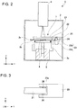
- FIG. 2 is a cross-sectional view of the additive manufacturing machine 1, similar to FIG. 1 , but taken from a different direction.
- the powder feeder mechanism 7 has an arm portion 21, a smoothing plate 22, a guide mechanism 23, a drive mechanism 24, and a connective portion 25.
- the guide mechanism 23 has a guide rail 23a and a slider 23b.
- the guide rail 23a is held to the front end of the flange portion 3b of the manufacturing box 3 in the second direction Y.
- the guide rail 23a extends parallel to the first direction X.
- the slider 23b is slidably supported on the guide rail 23a.
- the arm portion 21 is connected to the slider 23b.
- the arm portion 21 is made of an elongated member having a given length.
- the slider 23b is securely fixed to one longitudinal end of the arm portion 21.
- the arm portion 21 is supported to the guide mechanism 23.
- the longitudinal direction of the arm portion 21 is parallel to the second direction Y.
- the longitudinal length of the arm portion 21 is set greater than at least the length from one end of the support stage 4 to the other end in the second direction Y. Therefore, the arm portion 21 extends from one end of the support stage 4 to the other end in the second direction Y.
- the smoothing plate 22 is mounted to the rear end of the arm portion 21 in the third direction Z, the rear end being opposite to the manufacturing box 3 and to the support stage 4.
- the smoothing plate 22 is shaped generally in the form of a planar plate.
- the longitudinal direction of the smoothing plate 22 extends parallel to the second direction Y in the same way as the arm portion 21.
- the powdered material M1 is fed onto the working surface 4a of the support stage 4 and smoothed out at a given height in the third direction Z. Consequently, a powder layer of the powdered material M1 is formed on the working surface 4a of the support stage 4.
- the guide mechanism 23 that supports the arm portion 21 is rigidly fixed to the manufacturing box 3 and so if the box 3 expands thermally and becomes displaced in the third direction Z, the arm portion 21 and the guide mechanism 23 are also displaced in the third direction Z together with the manufacturing box 3. This can maintain constant the positional relationship of the manufacturing box 3 to the arm portion 21 and the smoothing plate 22. Consequently, it is possible to prevent mechanical interference of the arm portion 21 and the smoothing plate 22 with the manufacturing box 3.
- the connective portion 25 is connected to the front end of the arm portion 21 in the second direction Y.
- the connective portion 25 is supported by the drive mechanism 24 so as to be movable in the first direction X.
- the drive mechanism 24 is fixedly secured to the inner wall surface of the processing chamber 2 on the side of its front end in the second direction Y.
- the drive mechanism 24 moves the connective portion 25 in the first direction X by means of a chain drive, a belt drive, a gear drive, or other driving means.
- FIG. 3 is a plan view illustrating the manner in which the connective portion 25 and the arm portion 21 are connected together.
- the connective portion 25 is provided with a connective recessed portion 25a in which a rear end portion of the arm portion 21 is inserted.
- the connective recessed portion 25a is recessed in the second direction Y.
- the opposite ends of the connective recessed portion 25a in the third direction Z and its rear end in the second direction Y are open.
- the connective portion 25 supports the arm portion 21 from both sides of the first direction X that is the direction of movement of the arm portion 21.
- a gap is formed between the front end of the connective recessed portion 25a in the second direction Y and the arm portion 21.
- Substantially semispherical abutting pins 26 are mounted to the surface of the connective recessed portion 25a that is opposite to the arm portion 21 in the first direction X.
- the abutting pins 26 abut on the arm portion 21, each at one point.
- the abutting pins 26 are made of a shock-absorbing material having a relatively low Q and thus can absorb vibrations from the drive mechanism 24.
- the connective portion 25 transmits force to the arm portion 21 in the first direction X.
- the opposite ends of the connective recessed portion 25a in the third direction Z are open, and the gap is formed between the arm portion 21 and the front end of the connective recessed portion 25a in the second direction Y. That is, the connective portion 25 transmits force to the arm portion 21 only in its direction of movement, i.e., the first direction X, not either in the second direction Y or in the third direction Z different from the direction of movement of the arm portion 21.
- the arm portion 21 is displaced in the third direction Z by thermal expansion of the manufacturing box 3, the arm portion 21 can be displaced in the third direction Z within the connective recessed portion 25a. In consequence, if the manufacturing box 3 expands thermally, it is possible to prevent application of mechanical load to the point of connection where the connective portion 25 is coupled to the arm portion 21.
- the drive mechanism 24 is rigidly secured to the inner wall surface of the processing chamber 2 that is made of a member different from that of the manufacturing box 3. Therefore, during operation of the drive mechanism 24, transmission of the resulting vibrations to the manufacturing box 3 can be suppressed.
- the processing chamber 2 has been set forth as a support member that provides support of the drive mechanism 24.
- the present invention is not restricted to this example. It suffices that the support member be made of a member different from that of the manufacturing box 3.
- the support member may be mounted inside the processing chamber 2.
- the arm portion 21 and the connective portion 25 have been set forth as being connected together.
- the invention is not restricted to this example.
- the connective portion 25 may be connected to the slider 23b of the guide mechanism 23.
- FIG. 4 is a plan view of the manufacturing box 3.
- FIG. 5 is a cross-sectional view of the manufacturing box 3 and the support base 6.
- the cylindrical portion 3a of the manufacturing box 3 is shaped cylindrically.
- the flange portion 3b is shaped in the form of a circular disk and provided with three support grooves 31 in the rear end surface of the flange portion 3b as viewed in the third direction Z, i.e., in the bottom surface.
- the three support grooves 31 are equally spaced from each other circumferentially of the flange portion 3b around the cylindrical portion 3a.
- Each of the support grooves 31 is recessed like a letter V from the bottom surface of the flange portion 3b in the positive third direction Z, i.e., upwardly.
- the support grooves 31 have their top portions on the side of the front end of the flange portion 3b in the third direction Z, the top portions extending radially about the center Q1 of the manufacturing box 3.
- Support pins 32 mounted in and on the support base 6 are inserted into the support grooves 31, respectively.
- the support grooves 31 are supported by their respective support pins 32 so as to be slidable radially about the center Q1 of the cylindrical portion 3a.
- the support pins 32 are mounted on a supportive surface 6a of the support base 6 that is at the front end of the support base 6 in the third direction Z.
- the support grooves 31 and the support pins 32 together constitute a support mechanism or support structure that mechanically supports the manufacturing box 3.
- the manufacturing box 3 When the manufacturing box 3 is heated, the flange portion 3b expands thermally as well as the cylindrical portion 3a. Therefore, in the conventional additive manufacturing machine described above, there is a difference in coefficient of expansion between those portions of the manufacturing box which are respectively held and not held and, therefore, the manufacturing box is distorted. As a result, when the manufacturing box of the conventional additive manufacturing machine expands thermally, the position of the center Q1 of the manufacturing box shifts, thus deteriorating the fabrication accuracy of additive manufacturing.
- the manufacturing box 3 of the present embodiment if the flange portion 3b expands thermally in the first direction X and in the second direction Y, the three support grooves 31 slide on their respective support pins 32. Because the three support grooves 31 are equidistantly arranged peripherally of the flange portion 3b and because their top portions are arranged radially about the center Q1, the whole flange portion 3b expands uniformly radially outwardly of the flange portion 3b. Consequently, if the manufacturing box 3 expands thermally, the position of the center Q1 of the box 3 can be prevented from varying. Hence, the fabrication accuracy of additive manufacturing can be improved.
- the rear end of the cylindrical portion 3a of the manufacturing box 3 in the third direction Z is not fixed but is a free end. Therefore, if the manufacturing box 3 expands thermally, the cylindrical portion 3a expands toward the free end, i.e., the rear end in the third direction Z. This can suppress variation of the position of the front end of the manufacturing box 3 in the third direction Z.
- a heat shield (not shown) is disposed between the cylindrical portion 3a of the manufacturing box 3 and the support base 6 to prevent radiation and transfer of heat from the cylindrical portion 3a of the box 3 to the support base 6.
- the support grooves 31 are formed in the flange portion 3b and slidably supported by the support pins 32.
- the support mechanism for the manufacturing box 3 is not restricted to this.
- the support mechanism may be so designed that the support grooves are formed in the support bases 6, and the support pins are mounted to the flange portion 3b.
- the manufacturing box 3 may be supported by radially extending rails.
- the manufacturing box 3 is supported at three points by the three support mechanisms.
- the present invention is not restricted to this example.
- four or more support mechanisms may be provided, and the manufacturing box 3 may be supported at four or more points.
- FIG. 6 is a schematic cross-sectional view illustrating the manner in which a three-dimensional object is built with the additive manufacturing machine 1.
- the stage drive mechanism 5 is driven to place the support stage 4 either into a position lower than the top surface of the flange portion 3b of the manufacturing box 3 by a given spacing in the third direction Z or into a position where the working surface 4a of the support stage 4 and the top surface of the flange portion 3b are flush with each other.
- the given spacing is equal to the thickness, taken in the third direction Z, of the layer of the powdered material M spread subsequently.
- the drive mechanism 24 for the powder feeder mechanism 7 is driven to move the connective portion 25 in the first direction X.
- This moves the arm portion 21 connected to the connective portion 25 along the guide rail 23a of the guide mechanism 23 to thereby cause the powdered material M1 fed out of the powder reservoirs 9 to be carried onto the working surface 4a of the support stage 4.
- the arm portion 21 moves in the first direction X.
- a layer of the powdered material M1 is formed on the working surface 4a of the support stage 4 by the smoothing plate 22.
- vibrations of the drive mechanism 24 in the second direction Y and in the third direction Z are not transmitted to the arm portion 21 and so a flat layer of the powdered material M1 can be formed on the working surface 4a of the support stage 4.
- the electron beam L1 is emitted from the electron gun 8 toward the layer of powdered material M1 in accordance with two-dimensional shapes obtained by slicing a pre-designed three-dimensional model of a 3D object incrementally, i.e., at regular intervals of thickness.
- the regions of the powdered material M1 which correspond to the two-dimensional shapes are molten.
- the molten powdered material M1 condenses into solidified powder P1.
- the support stage 4 is lowered by a given height by the stage drive mechanism 5. Then, the powdered material M1 is spread over the immediately previously formed, underlying layer. The electron beam L1 is emitted to the region of the new layer of the powdered material M1 which corresponds to a two-dimensional shape for the new layer, thus melting and solidifying the region of the powdered material M1.
- These processing steps are repeated to stack molten and solidified layers of powdered material M1 on top of each other. As a result, as shown in FIG. 6 , a three-dimensional object K1 is built inside the cylindrical portion 3a of the manufacturing box 3.
- the manufacturing box 3 When the three-dimensional object K1 is built, if the manufacturing box 3 is heated and expands thermally, the positional relationship of the arm portion 21 and the smoothing plate 22 to the manufacturing box 3 can be maintained constant because the guide mechanism 23 supporting the arm portion 21 and the smoothing plate 22 is arranged within the manufacturing box 3 as described previously. Thus, mechanical interference of the arm portion 21 and the smoothing plate 22 with the manufacturing box 3 can be prevented.
- FIG. 7 is a schematic cross-sectional view of this additive manufacturing machine.
- the additive manufacturing machine associated with the second embodiment is generally indicated by reference numeral 51 and similar to the additive manufacturing machine 1 associated with the first embodiment except for the configuration of the powder feeder mechanism. Therefore, only the powder feeder mechanism is set forth here.
- Those components of the additive manufacturing machine 51 which are common to their counterparts of the additive manufacturing machine 1 are indicated by the same reference numerals as in the foregoing figures and a repetition of the description thereof is omitted.
- the powder feeder mechanism 57 has the arm portion 21, the smoothing plate 22, a first guiding mechanism 23A, a second guiding mechanism 23B, the drive mechanism 24, and the connective portion 25.
- the first guiding mechanism 23A is disposed at the front end of the flange portion 3b of the manufacturing box 3 in the second direction Y.
- the second guiding mechanism 23B is disposed at the rear end of the flange portion 3b of the manufacturing box 3 in the second direction Y.
- the arm portion 21 has a longitudinal front end, i.e., front end in the second direction Y, supported by the first guiding mechanism 23A.
- the additive manufacturing machine 51 having the powder feeder mechanism 57 described just above can yield advantageous effects similar to those produced by the additive manufacturing machine 1 associated with the first embodiment.
- FIG. 8A is a plan view of the arm portion.
- FIG. 8B is a schematic cross-sectional view of the powder feeder mechanism.
- a fixed slot 21a is formed at the longitudinal rear end of the arm portion 21B in the second direction Y.
- the slot 21a is elongated over a given length in the second direction Y.
- a set screw 59 has a shank inserted in the fixed slot 21a.
- the rear end of the arm portion 21B in the second direction Y is mounted to the slider 23b of the second guiding mechanism 23B by the set screw 59.
- a compression coil spring 59a is interposed as a biasing member between the head of the set screw 59 and the rear end of the arm portion 21B.
- the rear end of the arm portion 21B is biased toward the slider 23b by the compression coil spring 59a. Consequently, the rear end of the arm portion 21B is supported to the slider 23b of the second guiding mechanism 23B so as to be slidable in the second direction Y.
- the biasing member is not limited to the compression coil spring 59a. Alternatively, a leaf spring or various other members made of rubber or other resilient material may also be used.
- the additive manufacturing machine associated with the modified embodiment is similar in configuration to the additive manufacturing machine 1 associated with the first embodiment and so a description of such similarities is omitted.
- the additive manufacturing machine having this powder feeder mechanism 57B can yield advantageous effects similar to those produced by the additive manufacturing machine 1 associated with the first embodiment.
- FIG. 9 is a plan view of the manufacturing box and support base of the additive manufacturing machine associated with the third embodiment.
- FIG. 10 is a side elevation of the manufacturing box and support base.
- the additive manufacturing machine associated with the third embodiment is similar to the additive manufacturing machine 1 associated with the first embodiment except for the configurations of the manufacturing box and support base. Therefore, only the manufacturing box and support base are described herein, and those components of this additive manufacturing machine which are common to their counterparts of the additive manufacturing machine 1 associated with the first embodiment are indicated by the same reference numerals as in the foregoing figures and a repetition of the description thereof is omitted.
- a manufacturing box 63 has a cylindrical portion 63a of square cross section and a rectangular flange portion 63b.
- the flange portion 63b is provided with three support grooves 71 in the rear end surface (i.e., the bottom surface) of the flange portion 63b as taken in the third direction Z.
- the three support grooves 71 are arranged at regular intervals circumferentially of a virtual circle R1.
- the center Q1 of the virtual circle R1 lies at the center of gravity of the manufacturing box 63.
- Each support groove 71 is recessed like a letter V.
- the support grooves 71 have their respective top portions at their front ends in the third direction Z, and these top portions extend radially about the center Q1.
- Support pins 72 are mounted on the support base 66 (described later) and inserted into the support grooves 71, respectively.
- the flange portion 63b of the manufacturing box 63 is supported by the support base 66.
- the support base 66 is rigidly secured to the inner wall surface of the processing chamber 2 and protrudes from the inner wall surface of the processing chamber 2 in the first direction X.
- the support base 66 is opposite to the flange portion 63b around the cylindrical portion 63a of the manufacturing box 63.
- the support base 66 has three support portions 66a which protrude in the positive third direction Z from the front end surface of the support base 66 as viewed in the third direction Z.
- the three support portions 66a are opposite to the three support grooves 71, respectively, formed in the flange portion 63b.
- Support pins 72 to be inserted into the support grooves 71 are mounted to the support portions 66a, respectively.
- the support grooves 71 slide over the support pins 72, respectively.
- the additive manufacturing machine associated with the third embodiment is similar in configuration with the additive manufacturing machine 1 associated with the first embodiment and so a description of such similarities is omitted.
- the additive manufacturing machine having these manufacturing box 63 and support base 66 can yield advantageous effects similar to those provided by the additive manufacturing machine 1 associated with the first embodiment.
- FIG. 11 is a schematic cross-sectional view of this additive manufacturing machine.
- the additive manufacturing machine associated with the fourth embodiment is generally indicated by reference numeral 81 and similar to the additive manufacturing machine 1 associated with the first embodiment except for the configurations of a manufacturing box and of support mechanisms for the manufacturing box. Therefore, only the manufacturing box and support mechanisms for the manufacturing box are described here.
- Those components of the additive manufacturing machine 81 which are common to their counterparts of the additive manufacturing machine 1 associated with the first embodiment are indicated by the same reference numerals as in the foregoing figures and a repetition of the description thereof is omitted.
- the manufacturing box, 83 has a cylindrical portion 87 and a reference plate 88 in the form of a flat plate.
- the reference plate 88 is firmly secured to the support base 6 and to the inner wall surface of the processing chamber 2.
- a guide mechanism for the powder feeder mechanism 7 is held to the reference plate 88.
- the cylindrical portion 87 is detachably mounted to the rear end surface of the reference plate 88 in the third direction Z, i.e., the bottom surface.
- the support stage 4 that is moved in the third direction Z by the stage drive mechanism 5 is disposed in the interior of the cylindrical portion 87.
- the front end of the cylindrical portion 87 in the third direction Z is in abutment with the bottom surface of the reference plate 88.
- a push spring 86 representing a push mechanism is mounted to the rear end of the cylindrical portion 87 in the third direction Z.
- the front end of the push spring 86 in the third direction Z is mounted to the cylindrical portion 87, while the rear end of the spring 86 in the third direction Z is mounted to a spring receiving portion 85 mounted in the processing chamber 2.
- the push spring 86 biases the cylindrical portion 87 in the positive third direction Z. Consequently, the cylindrical portion 87 is pushed against the reference plate 88 by the push spring 86 and squeezed between the push spring 86 and the reference plate 88.
- the cylindrical portion 87 of the manufacturing box 83 can be retained without using a securing mechanism or securing means such as a set screw. Consequently, the cylindrical portion 87 of the manufacturing box 83 can be easily mounted and detached.
- the push spring 86 is used as the push mechanism.
- the invention is not restricted to this example.
- an air spring or air cylinder utilizing air pressure may also be used as the push mechanism.
- the reference plate 88 of the manufacturing box 83 is not displaced in the third direction Z upon thermal expansion but the shaft portion 4d for moving the support stage 4 is elongated, due to thermal expansion, in the positive third direction Z as indicated by the upward white arrow in FIG. 12 . Consequently, the position of the shaft portion 4d on the working surface 4a of the support stage 4 in the third direction Z is displaced due to thermal expansion. This gives rise to error in the amount of movement of the support stage 4. As a result, the conventional additive manufacturing machine has the problem that a powder layer of a desired thickness cannot be formed due to thermal expansion of the drive mechanism for moving the support stage.
- the amount of elongation of the shaft portion 4d caused by thermal expansion can be calculated by temperature measurements while using the reference plate 88 as a reference because the position of the reference plate 88 in the third direction Z does not vary.
- the stage drive mechanism 5 can move the support stage 4 into position by correcting the amount of movement of the support stage 4 with the calculated amount of elongation of the shaft portion 4d. As a result, a powder layer can be formed to an appropriate thickness.
- the additive manufacturing machine 81 is similar in configuration with the additive manufacturing machine 1 associated with the first embodiment and so a description of such similarities is omitted.
- the additive manufacturing machine 81 having this configuration can yield advantageous effects similar to those provided by the additive manufacturing machine 1 associated with the first embodiment.
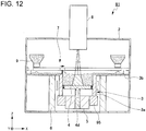
- FIG. 12 is a schematic cross-sectional view of this additive manufacturing machine.
- the additive manufacturing machine associated with the fifth embodiment is generally indicated by reference numeral 91 and similar to the additive manufacturing machine 1 associated with the first embodiment except for the position at which the stage drive mechanism 5 is mounted. Therefore, only the installation position of the stage drive mechanism 5 is described here; those parts of the additive manufacturing machine 91 which are common to their counterparts of the additive manufacturing machine 1 associated with the first embodiment are indicated by the same reference numerals as in the foregoing figures and a repetition of the description thereof is omitted.
- the stage drive mechanism 5 is mounted via a mounting member 95 to the rear end of the cylindrical portion 3a of the manufacturing box 3 as viewed in the third direction Z.
- the cylindrical portion 3a of the manufacturing box 3 is elongated in the negative third direction Z due to thermal expansion as indicated by the downward white arrows.
- the elongation of the shaft portion 4d and the elongation of the cylindrical portion 3a cancel each other. This can suppress displacements of the position of the working surface 4a of the support stage 4 upon thermal expansion. Hence, the support stage 4 can be moved into position.
- the additive manufacturing machine 91 is similar in configuration with the additive manufacturing machine 1 associated with the first embodiment and so a description of such similarities is omitted.
- the additive manufacturing machine 91 of this configuration can yield advantageous effects similar to those provided by the additive manufacturing machine 1 associated with the first embodiment.
- FIGS. 13 and 14 show the manufacturing box of this additive manufacturing machine.
- FIG. 14 is a plan view of the manufacturing box, as viewed on lines A-A of FIG. 13 .
- the additive manufacturing machine associated with the sixth embodiment is similar to the additive manufacturing machine 1 associated with the first embodiment except for the configurations of manufacturing box and support base. Therefore, only the manufacturing box and support base are described here; those portions which are common to their counterparts of the additive manufacturing machine 1 associated with the first embodiment are indicated by the same reference numerals as in the foregoing figures and a repetition of the description thereof is omitted.
- the manufacturing box, 103 is shaped cylindrically and has a cylindrical portion 103a.
- Three support pins 112 are mounted on the outer peripheral surface of the cylindrical portion 103a.
- the support pins 112 protrude substantially perpendicularly from the outer peripheral surface of the cylindrical portion 103a and project radially outwardly.
- the three support pins 112 are arranged equiangularly peripherally of the cylindrical portion 103a.
- the support pins 112 protrude radially about the center Q1 of the manufacturing box 103 and are placed in support grooves 115 formed in a support base 106 (described later).
- the number of the support pins 112 is not restricted to three. The number may be four or more. If four or more support pins 112 are provided, the support pins 112 are preferably arranged at regular angular intervals about the center Q1 of the cylindrical portion 103a, i.e., arranged rotationally symmetrically.
- the shape of the cylindrical portion 103a of the manufacturing box 103 is not restricted to a cylindrical form.
- the cylindrical portion 103a may be shaped into a cylinder of a square or hexagonal cross section, or a cylinder of any other cross-sectional shape in the same way as for the manufacturing box 63 associated with the third embodiment.
- the three support grooves 115 are formed in a support surface 106a of the support base 106 that is at the front end in the third direction Z.
- the support grooves 115 are recessed in the negative third direction Z from the support surface 106a, i.e., recessed downwardly.
- Each of the support grooves 115 extends a given length from the inner wall surface of the support base 106 radially outwardly.
- the support grooves 115 extend radially about the center Q1 of the support base 106 and of the manufacturing box 103 which is supported to the support base 106.
- the support pins 112 are arranged in the support grooves 115, respectively.
- each support groove 115 The width (lateral dimension) and depth (depthwise dimension taken in the third direction Z) of each support groove 115 are set substantially equal to the outside diameter of each support pin 112. Therefore, when the support pins 112 are placed in the support grooves 115, peripheral movement of the manufacturing box 103 can be restricted by the support pins 112 and the support grooves 115.
- a gap W1 is formed between the end of each support pin 112 on the opposite side of the cylindrical portion 103a, i.e., the front end, and the end of a respective one of the support grooves 115 on the opposite side of the inner wall surface of the support base 106.
- the length of the gap W1 is so set that if the manufacturing box 103 and the support pins 112 expand thermally, the box 103 and the support base 106 will not mechanically interfere with each other.
- the gaps W1 formed between the support pins 112 and the support grooves 115 permit the support pins 112 to slide in their respective support grooves 115.
- the three support pins 112 and the three support grooves 115 are arranged radially about the center Q1 of the manufacturing box 103 and rotationally symmetrically. Therefore, the three support pins 112 thermally expand radially outwardly uniformly about the center Q1 of the manufacturing box 3. This can prevent the position of the center Q1 of the manufacturing box 103 from varying upon thermal expansion of the box 103, thus enhancing the accuracy of the manufacturing.
- Pin retainers 107 are removably mounted on the support surface 106a of the support base 106 and placed at positions on the support surface 106a where the support grooves 115 are formed.
- the pin retainers 107 are mounted on the support base 106 by means of securing bolts 107a. Furthermore, the pin retainers 107 restrict the support pins 112 disposed in the support grooves 115 from moving in the positive third direction Z, i.e., upwardly.
- a plate 110 is disposed on the upper end of the manufacturing box 103 and over the upper end of the support base 106, as viewed in the positive third direction Z.
- the plate 110 is secured to the front end of the cylindrical portion 103a of the manufacturing box 103 in the positive third direction Z, i.e., the upper end, for example, by means of set screws.
- the plate 110 is not in contact with the support base 106. This can suppress transmission of heat of the plate 110 to the support base 106.
- a heat shield may be placed between the plate 110 and the support base 106 to prevent radiation of heat from the plate 110 to the support base 106.
- the plate 110 is provided with a substantially circular opening 110a which is nearly equal in size to the cylindrical interior hole in the cylindrical portion 103a of the manufacturing box 103.
- the opening 110a in the plate 110 faces both the interior hole of the cylindrical portion 103a and the support stage 4.
- Powdered material M1 fed from the powder reservoir 9 (see FIG. 1 ) is placed on the upper surface of the plate 110 as viewed in the positive third direction Z.
- the plate 110 covers the pin retainers 107.
- the plate 110 plays the same role as the flange portion 3b of the manufacturing box 3 associated with the first embodiment or as the reference plate 88 associated with the fourth embodiment.
- the additive manufacturing machine associated with the sixth embodiment is similar in configuration with the additive manufacturing machine 1 associated with the first embodiment and so a description of such similarities is omitted.
- the additive manufacturing machine constructed in this way yields advantageous effects similar to those produced by the additive manufacturing machine 1 associated with the first embodiment.
- the support stage 4 is moved in the positive third direction Z, i.e., elevated upwardly in the up/down direction.
- the support stage 4 is sometimes elevated by an amount equal to one or a given number of layers.
- the pin retainers 107 suppress the support pins 112 mounted to the manufacturing box 103 from moving in the third direction Z. Consequently, when the support stage 4 is moved upward, the friction of the manufacturing box 103 against the built 3D object K1, powdered material M1, and slidable member 14 can prevent the manufacturing box 103 from floating up together with the support stage 4. As a result, when the powdered material M1 is spread again, the manufacturing box 103 can be prevented from varying in position in the third direction Z. Thus, the powdered material M1 can be spread again accurately.
- FIG. 15 schematically shows the configuration of this additive manufacturing machine.
- the additive manufacturing machine associated with the seventh embodiment is similar to the additive manufacturing machine 1 associated with the first embodiment except for the configuration of the powder feeder mechanism. Therefore, only the powder feeder mechanism is described here. Those components of the additive manufacturing machine associated with the seventh embodiment which are common with their counterparts of the additive manufacturing machine 1 associated with the first embodiment are indicated by the same reference numerals as in the foregoing figures and a repetition of the description thereof is omitted.
- the powder feeder mechanism, 207 has an arm portion 221, a smoothing plate 22, a first guiding mechanism 223A, a second guiding mechanism 223B, a drive mechanism 24, and a connective portion 25.
- the smoothing plate 22, drive mechanism 24, and connective portion 25 are identical in configuration with their respective counterparts 22, 24, and 25 associated with the first embodiment and so a description thereof is omitted.
- the first guiding mechanism 223A is disposed at the front end of the manufacturing box 3 in the second direction Y.
- the first guiding mechanism 223A has a slider 226 and a guide rail 227.
- the guide rail 227 is disposed at the front end of the manufacturing box 3 in the second direction Y and runs parallel to the first direction X.
- the guide rail 227 has a substantially cylindrical guide portion 227a which is disposed at the front end of the guide rail 227 in the third direction Z, i.e., at a higher position in the up/down direction.
- the slider 226 is supported to the guide portion 227a so as to be slidable in the first direction X.
- the slider 226 is disposed at the longitudinal front end of the arm portion 221, i.e., at the front end in the second direction Y.
- the slider 226 has a sliding surface 226a which is recessed circularly according to the curvature of the outer peripheral surface of the guide portion 227a.
- the sliding surface 226a slides on the outer peripheral surface of the guide portion 227a. Therefore, the slider 226 is supported to the guide rail 227 such that it can not only move in the first direction X but also rotate about the central axis of the guide portion 227a.
- the second guiding mechanism 223B is disposed at the rear end of the manufacturing box 3 in the second direction Y.
- the second guiding mechanism 223B has a guide roller 228 and a guide surface portion 229.
- the guide surface portion 229 is shaped substantially in the form of a flat plate and placed at the rear end of the manufacturing box 3 in the second direction Y.
- the guide surface portion 229 extends parallel to the first direction X.
- the guide roller 228 is rotatably disposed at the longitudinal rear end of the arm portion 221, i.e., rear end in the second direction Y.
- the guide roller 228 is rotatably in contact with the front surface of the guide surface portion 229 in the third direction Z, i.e., its upper surface.
- the contact surface 228a of the guide roller 228 in contact with the guide surface 229 is curved relative to the second direction Y and the third direction Z.
- the additive manufacturing machine associated with the seventh embodiment is similar in configuration to the additive manufacturing machine 1 associated with the first embodiment and so a description of such similarities is omitted.
- the additive manufacturing machine constructed in this way can yield advantageous effects similar to those produced by the additive manufacturing machine 1 associated with the first embodiment.
- the positions of the first guiding mechanism 223A and of the second guiding mechanism 223B in the third direction Z may vary due to temperature nonuniformity within the manufacturing box 3, temperature gradient across the powder feeder mechanism 207, difference in thermal conduction between the first guiding mechanism 223A and the second guiding mechanism 223B, and other factors.
- the slider 226 is supported so as to be rotatable about the central axis of the guide portion 227a of the guide rail 227.
- the slider 226 rotates about the guide portion 227a. Consequently, if a positional deviation in the third direction Z occurs between the first guiding mechanism 223A and the second guiding mechanism 223B, the slider 226 smoothly slides on the guide portion 227a without rattling.
- the arm portion 221 tilts relative to the second direction Y.
- the contact surface 228a of the guide roller 228 is curved. Therefore, if the arm portion 221 tilts, the contact surface 228a of the guide roller 228 can be reliably brought into contact with the guide surface portion 229.
- the powder feeder mechanism 207 associated with the seventh embodiment if various components undergo asymmetrical thermal expansions, occurrence of excessive frictional resistances and mechanical loads can be suppressed during operation of the powder feeder mechanism 207. As a result, the arm portion 221 and the smoothing plate 22 can be smoothly moved. In addition, mechanical interference between the smoothing plate 22 and the manufacturing box 3 can be prevented. The powdered material M1 can be smoothed out.
- FIG. 16 schematically shows the configuration of this additive manufacturing machine.
- FIG. 17 is an enlarged perspective view illustrating the manner in which the connector portion and the arm portion are connected together.
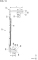
- FIG. 18 is a front elevation of the arm portion.
- the additive manufacturing machine associated with the eighth embodiment is similar to the additive manufacturing machine 1 associated with the first embodiment except for the configuration of the powder feeder mechanism. Therefore, only the powder feeder mechanism is described here. Those components of the additive manufacturing machine associated with the eighth embodiment which are common with their counterparts of the additive manufacturing machine 1 associated with the first embodiment are indicated by the same reference numerals as in the foregoing figures and a repetition of the description thereof is omitted.
- the powder feeder mechanism, 307 has an arm portion 321, a smoothing plate 22, a first guiding mechanism 323A, a second guiding mechanism 323B, a drive mechanism 24, and a connector portion 325.
- the smoothing plate 22 and drive mechanism 24 are similar in configuration with the smoothing plate 22 and drive mechanism 24, respectively, associated with the first embodiment and so a description thereof is omitted.
- the arm portion 321 has a first arm supporting portion 331 and a second arm supporting portion 332.
- the first arm supporting portion 331 is located at the longitudinal front end of the arm portion 321, i.e., at the front end in the second direction Y.
- the first arm supporting portion 331 has a first member 333 and a second member 334.
- Each of the first and second members 333, 334 is shaped generally in the form of a flat plate.
- the first member 333 and the second member 334 are secured with set screws 340.
- the first member 333 and the second member 334 are fastened together at their rear ends in the third direction Z, i.e., at their lower ends in the up/down direction.
- the front end of the second member 334 in the third direction Z which is on the opposite side of its end secured to the first member 333, i.e., upper end in the up/down direction, is secured to the longitudinal front end of the arm portion 321 with other set screws 340.
- a slider 326 constituting a part of the first guiding mechanism 323A is secured to the front end of the first member 333 in the third direction Z, the front end facing away from the end of the first member 333 secured to the second member 334.
- the slider 326 has a circularly recessed sliding surface 326a in the same way as the slider 226 associated with the seventh embodiment.
- the sliding surface 326a of the slider 326 associated with the eighth embodiment faces in the positive third direction Z, i.e., upward in the up/down direction.
- the slider 326 is slidably supported to the guide rail 327 that also constitutes a part of the first guiding mechanism 323A.
- the guide rail 327 is positioned on the front end of the manufacturing box 3 in the second direction Y.
- the guide rail 327 has a generally cylindrical guide portion 327a in the same way as the guide rail 227 associated with the seventh embodiment.
- the guide portion 327a associated with the eighth embodiment is disposed at the rear end of the guide rail 327 in the third direction Z, i.e., beneath the guide rail 327 as viewed in the up/down direction, and faces downward in the up/down direction. Consequently, the guide rail 327 associated with the eighth embodiment can prevent the powdered material M1 and so on from adhering to the guide portion 327a. This enables smooth sliding motion of the slider 326 along the guide portion 327a.
- the second member 334 is provided with a connection hole 334a in which a connecting pin 325a mounted on the connector portion 325 is inserted.
- the connecting pin 325a protrudes in the negative second direction Y from the connector portion 325.
- connection hole 334a formed in the second member 334 is a slot elongated in the third direction Z.
- the length of the opening of the connection hole 334a in the first direction X is set nearly equal to the outside diameter of the connecting pin 325a. Therefore, when the connecting pin 325a is inserted into the connection hole 334a, the pin 325a abuts against the side surface of the connection hole 334a lying in the first direction X. Consequently, the connector portion 325 can transmit force to the arm portion 321 via the connection pin 325a in the first direction X.
- connection hole 334a is a slot elongated in the third direction Z
- the force in the connection portion 325 in the third direction Z is not transmitted to the second member 334, i.e., the arm portion 321.
- a gap is present between the connector portion 325 and the second member 334 and extends in the second direction Y. Therefore, the force on the connector portion 325 acting in the second direction Y is not transmitted to the second member 334, i.e., the arm portion 321.
- connection hole 334a is formed in the second member 334 that is the arm portion 321.
- the present invention is not restricted to this.
- the connection hole may be formed in the connector portion 325, and the connecting pin may be mounted to the second member 334.
- connection mechanism composed of the connecting pin 325a and the connection hole 334a may be applied to additive manufacturing machines associated with the first to seventh embodiments.
- the second arm supporting portion 332 is disposed at the longitudinal rear end of the arm portion 321, i.e., at the rear end in the second direction Y.
- the second arm supporting portion 332 has a first member 335 and a second member 336 in the same way as the first arm supporting portion 331.
- Each of the first member 335 and the second member 336 is shaped substantially in the form of a flat plate.
- the first member 335 and the second member 336 are fastened together with set screws 340.
- the first member 335 and the second member 336 are secured together at their rear ends in the third direction Z, i.e., at their lower ends as viewed in the up/down direction.
- the front end of the second member 336 in the third direction Z that is on the opposite side of the position where the second member 336 is secured to the first member 335, i.e., the upper end in the up/down direction, is secured to the longitudinal rear end of the arm portion 321 with set screws 340.
- a guide roller 328 that constitutes the second guiding mechanism 323B together with a guide surface portion 329 is mounted at the front end of the first member 335 in the third direction Z which is on the opposite side of the position where the first member 335 is secured to the second member 336. Since the configurations of the guide roller 328 and guide surface portion 329 are similar to the configurations of the guide roller 228 and guide surface portion 229 associated with the seventh embodiment, a description thereof is omitted.
- a weight 338 is securely fixed to the second member 336 of the second arm supporting portion 332 and mounted at the rear end of the second member 336 in the second direction Y to assure that the guide roller 328 is brought into contact with the guide surface portion 329. Consequently, the arm portion 321 can be smoothly moved without rattling.
- the configuration of mounting of the weight 338 to the arm portion 321 may also be applied to the additive manufacturing machines associated with the first through seventh embodiments.
- the configurations of the first arm supporting portion 331 and the second arm supporting portion 332 are described in further detail by referring to FIG. 18 .
- the length S1 taken from the location of the first arm supporting portion 331 where it is secured to the slider 326 of the first member 333 to the location where the first arm supporting portion 331 is secured to the second member 334 is set shorter than the length T1 taken from the location of the second member 334 where it is secured to the first member 333 to the location where it is secured to the arm portion 321. That is, the length S1 of the first member 333 in the third direction Z is shorter than the length T1 of the second member 334 in the third direction Z.
- the length S2 taken from the location where the second arm supporting portion 332 is secured to the guide roller 328 of the first member 335 to the location where the second arm supporting portion 332 is secured to the second member 336 is set shorter than the length T2 taken from the location where the second member 336 is secured to the first member 335 to the location where the second member 336 is secured to the arm portion 321. That is, the length S2 of the first member 335 in the third direction Z is shorter than the length T2 of the second member 336 in the third direction Z.
- the first member 333 and the second member 334 of the first arm supporting portion 331 are made of different materials.
- the first member 335 and the second member 336 of the second arm supporting portion 332 are made of different materials.
- the first members 333 and 335 are made of materials having larger linear coefficients of expansion than those of the second members 334 and 336.
- the ratios of the lengths S1:T1 and S2:T2 of the first members 333, 335 and the second members 334, 336 in the third direction Z are set approximately equal to the inverse ratios of the linear coefficients of expansion of the first members 333, 335 and the second members 334, 336.
- the first member 333 expands in the positive third direction Z, i.e., upward in the up/down direction, from the location where the first member 333 is secured to the second member 334.
- the second member 334 expands in the negative third direction Z, i.e., downward in the up/down direction, from the location where the second member 334 is secured to the arm portion 321.
- the first member 333 is made of a material having a linear coefficient of expansion greater than that of the second member 334. Consequently, the coefficient of thermal expansion of the first member 333 in the third direction Z is greater than that of the second member 334.
- the length S1 of the first member 333 in the third direction Z is shorter than the length T1 of the second member 334 in the third direction Z.
- the ratio of the lengths S1:T1 is set equal to the inverse ratio of the linear coefficients of expansion of the first member 333 and the second member 334.
- the length of thermal expansion of the first member 333 in the positive third direction Z and the length of thermal expansion of the second member 334 in the negative third direction Z are almost equal to each other. Accordingly, the elongation of the first member 333 in the third direction Z due to thermal expansion can be canceled by the elongation of the second member 334 in the third direction Z due to thermal expansion.
- the first members 333, 335 and the second members 334, 336 are made of materials such that the linear coefficients of expansion of the materials of the first members 333, 335 are greater than those of the materials of the second members 334, 336.
- the present invention is not restricted to this.
- the first members 333, 335 are made of materials having linear coefficients of expansion smaller than those of the materials of the second members 334, 336.
- an arm support assembly consisting of the first arm supporting portion 331 and the second arm supporting portion 332 made of two materials having different linear coefficients of expansion according to their lengths in the third direction Z can also be applied to the additive manufacturing machines associated with the first through seventh embodiments.
- the additive manufacturing machine associated with the eighth embodiment is similar in configuration to the additive manufacturing machine 1 associated with the first embodiment and so a description thereof is omitted.
- the additive manufacturing machine constructed in this way can yield advantageous effects similar to those produced by the additive manufacturing machine 1 associated with the first embodiment.
- powder of metals such as titanium, aluminum, iron, or the like is used as a powdered material.
- resins can be used as powdered materials.
- an electron gun for emitting an electron beam is set forth as a heating mechanism for preheating and melting a powdered material.
- a laser light source producing laser light may also be used as the heating mechanism.
- parallel and perpendicular are used. What is meant by the term “parallel,” as used herein, is that there is a substantially parallel relationship in which the intended function can be accomplished. Similarly, what is meant by the term “perpendicular,” as used herein, is that there is a substantially perpendicular relationship in which the intended function can be accomplished.
Landscapes
- Engineering & Computer Science (AREA)
- Chemical & Material Sciences (AREA)
- Materials Engineering (AREA)
- Manufacturing & Machinery (AREA)
- Physics & Mathematics (AREA)
- Optics & Photonics (AREA)
- Mechanical Engineering (AREA)
- Plasma & Fusion (AREA)
- Powder Metallurgy (AREA)
Abstract
Description
- The present invention relates to an additive manufacturing machine for manufacturing a three-dimensional object by successively stacking thin layers of a powdered material on a support stage.
- In recent years, additive manufacturing for manufacturing a three-dimensional (3D) object on a layer-by-layer basis by laying down a powdered material as stacked thin layers has attracted attention. Various types of additive manufacturing techniques have been developed utilizing different powdered materials and different 3D object fabrication techniques.
- One known method of additive manufacturing starts with laying down a powdered material, for example, as stacked layers on the top surface of a powder support stage on a layer-by-layer basis. Then, only a two-dimensional structure portion of the layers of the powdered material over the stage which corresponds to one cross section through a 3D object to be built is molten by a heating mechanism consisting of an electron beam or laser beam. Such molten layers of the powdered material are stacked successively in the heightwise direction (z-direction) to thereby create the 3D object (see, for example, Patent document 1)
- Also,
Patent document 1 sets forth that a powder feeder makes sliding movement, i.e., moves over a manufacturing box, to thereby smooth out powdered material and that a layer of the powder is consequently formed on the support stage. - Patent document 1:
JP-A-2019-7072 - With the technique set forth in
Patent document 1, however, if the operation for creating the 3D object is performed for a long time, the manufacturing box accommodating the 3D object being created becomes heated and thermally expands. This presents the possibility that the smoothing plate of the powder feeder mechanism may mechanically interfere with the manufacturing box. - Furthermore, the technique set forth in
Patent document 1 suffers from the problem that vibrations of the mechanical drive portion is transmitted to the smoothing plate, whereby the powdered material cannot be smoothed out. - In view of the foregoing problems, the present invention has been made. It is an object of the present invention to provide an additive manufacturing machine which has a smoothing plate and a manufacturing box and which is capable of smoothing out a powdered material while preventing mechanical interference between the smoothing plate and the manufacturing box.
- An additive manufacturing machine which achieves the above-described object in accordance with the teachings of the present invention has a support stage, a manufacturing box, and a powder feeder mechanism. A powdered material for manufacturing a three-dimensional (3D) object is stacked as a series of layers on the support stage. The manufacturing box has a cylindrical portion on which the support stage is slidably disposed. The powder feeder mechanism feeds the powdered material onto the support stage and smooths out the powdered material.
- The powder feeder mechanism has an arm portion, a guide mechanism, a connective portion, and a drive mechanism. A smoothing plate for smoothing out the powdered material is fixedly secured to the arm portion. The guide mechanism is secured to the manufacturing box and supports the arm portion such that the arm portion can move in a first direction that is parallel to one surface of the support stage which defines a working surface. The connective portion is connected to the arm portion and transmits mechanical force to the arm portion only in the first direction. The drive mechanism is secured to a support member different from the manufacturing box and has a drive portion for moving the connective portion in the first direction.
- According to the inventive additive manufacturing machine, the powdered material can be smoothed out while preventing mechanical interference between the smoothing plate and the manufacturing box.
-
-
FIG. 1 is a schematic cross-sectional view of an additive manufacturing machine associated with a first embodiment of the present invention. -
FIG. 2 is a cross-sectional view similar toFIG. 1 , but taken from a different direction. -
FIG. 3 is a plan view illustrating the manner in which a connective portion and an arm portion of the additive manufacturing machine shown inFIGS. 1 and2 are connected together. -
FIG. 4 is a plan view of a manufacturing box of the additive manufacturing machine shown inFIGS. 1-3 . -
FIG. 5 is a cross-sectional view of the manufacturing box and a support stage of the additive manufacturing machine shown inFIGS. 1-4 . -
FIG. 6 is a schematic cross-sectional view illustrating the manner in which a three-dimensional object has been built with the additive manufacturing machine shown inFIGS. 1-5 . -
FIG. 7 is a schematic cross-sectional view of an additive manufacturing machine associated with a second embodiment of the present invention. -
FIG. 8A is a plan view of an arm portion of a modification of the additive manufacturing machine ofFIG. 7 . -
FIG. 8B is a schematic cross-sectional view of a powder feeder mechanism of the modification of the additive manufacturing machine ofFIG. 7 . -
FIG. 9 is a plan view of a manufacturing box and a support base of an additive manufacturing machine associated with a third embodiment of the invention. -
FIG. 10 is a side elevation of the manufacturing box and the support base of the additive manufacturing machine ofFIG. 9 . -
FIG. 11 is a schematic cross-sectional view of an additive manufacturing machine associated with a fourth embodiment of the invention. -
FIG. 12 is a schematic cross-sectional view of an additive manufacturing machine associated with a fifth embodiment of the invention. -
FIG. 13 is a cross-sectional view of a manufacturing box of an additive manufacturing machine associated with a sixth embodiment of the invention. -
FIG. 14 is a plan view of the manufacturing box shown inFIG. 13 . -
FIG. 15 is a schematic cross-sectional view of an additive manufacturing machine associated with a seventh embodiment of the invention. -
FIG. 16 is a schematic cross-sectional view of an additive manufacturing machine associated with an eighth embodiment of the invention. -
FIG. 17 is an enlarged perspective view of the connective portion and arm portion of the additive manufacturing machine shown inFIG. 16 , illustrating the manner in which the connective portion and the arm portion are connected together. -
FIG. 18 is a front elevation of the arm portion shown inFIG. 17 . - The preferred embodiments of the additive manufacturing machine of the present invention are hereinafter described with reference to
FIGS. 1 to 18 . In various figures, like components are indicated by like reference numerals. - First, a first embodiment of the additive manufacturing machine of the present invention is described by referring to
FIG. 1 , which is a schematic cross-sectional view of the additive manufacturing machine. - The additive manufacturing machine shown in
FIG. 1 is generally indicated byreference numeral 1 and operates to build a three-dimensional object by irradiating a powdered material such as a powdered metal (e.g., titanium, aluminum, or iron) with an electron beam to melt the material, and stacking layers of the solidified powdered material on top of each other. - As shown in
FIG. 1 , theadditive manufacturing machine 1 has ahollow processing chamber 2, amanufacturing box 3, asupport stage 4 in the form of a flat plate, astage drive mechanism 5, asupport base 6, apowder feeder mechanism 7, anelectron gun 8, and powder tanks orreservoirs 9. It is assumed that thesupport stage 4 has one surface (working surface) 4a parallel to a first direction X and that a second direction Y is perpendicular to the first direction X and parallel to theworking surface 4a of thestage 4. It is also assumed that a direction perpendicular to the workingsurface 4a of thesupport stage 4 is a third direction Z. - A vacuum pump (not shown) is connected to the
processing chamber 2. The air inside theprocessing chamber 2 is evacuated by the vacuum pump and so the inside of theprocessing chamber 2 is maintained as a vacuum. Themanufacturing box 3,support stage 4,stage drive mechanism 5,support base 6,powder feeder mechanism 7, andpowder reservoirs 9 are arranged inside theprocessing chamber 2. Theelectron gun 8 is mounted to the front end of theprocessing chamber 2 as viewed in the third direction Z, i.e., at the top of theprocessing chamber 2. Themanufacturing box 3 is supported on thesupport base 6 and placed at a position opposite to theelectron gun 8 in the third direction Z. - The
manufacturing box 3 has acylindrical portion 3a and aflange portion 3b representing a reference plate. The axial direction of thecylindrical portion 3a is parallel to the third direction Z. Thecylindrical portion 3a has open opposite end portions in the third direction Z. A powdered material M1 fed by the powder feeder mechanism 7 (described later) and a three-dimensional object built from the material M1 are accommodated in the hollow interior of thecylindrical portion 3a. - The
flange portion 3b is formed at the outer fringes of the upper end of thecylindrical portion 3a that is at the front end in the third direction Z. Theflange portion 3b is bent substantially vertically from the outer fringes of thecylindrical portion 3a. Theflange portion 3b is placed parallel to the first direction X and to the second direction Y. Afringe portion 3c (seeFIG. 2 ) is formed at the outer fringes of theflange portion 3b and protrudes in the positive third direction Z. - The
flange portion 3b is supported on thesupport base 6 that is disposed inside theprocessing chamber 2. Therefore, the axial front end of thecylindical portion 3a of themanufacturing box 3, i.e., upper end, is a fixed end, while the axial rear end of thecylindrical portion 3a, i.e., lower end, is a free end. The structure of themanufacturing box 3 and the structure of thesupport base 6 that supports themanufacturing box 3 are described in detail later. - The
powder reservoirs 9 for storing the powdered material M1 are disposed at opposite ends of theflange portion 3b in the first direction X. Also, thepowder reservoirs 9 are disposed over the front end of theflange portion 3b in the third direction Z, i.e., above theflange portion 3b. A volumetric feeder for dispensing a given amount of powdered material M1 is arranged on the side of a respective one of thepowder reservoirs 9 which is opposite to theflange portion 3b. Each volumetric feeder feeds a given amount of powdered material M1 to theflange portion 3b. - The
powder feeder mechanism 7 is disposed between the horizontal array of thepowder reservoirs 9 and theflange portion 3b. Thefeeder mechanism 7 carries the powdered material M1 from theflange portion 3b onto thesupport stage 4 and spreads the material M1 over thesupport stage 4. The structure of thepowder feeder mechanism 7 is described in detail later. - Inside the
cylindrical portion 3a of themanufacturing box 3, thesupport stage 4 is arranged so as to be slidable in the third direction Z. Thesupport stage 4 is shaped like a flat plate. The powdered material M1 is stacked in layers on the workingsurface 4a of thesupport stage 4 that is at the front end in the third direction Z. Aslidable member 14 having heat resistance and flexibility is mounted on the lateral end of thesupport stage 4. Theslidable member 14 is in slidable contact with the inner wall surface of thecylindrical portion 3a. - A shank or
shaft portion 4d is mounted to the opposite surface of thesupport stage 4 which faces away from the workingsurface 4a. Theshaft portion 4d protrudes from this opposite surface of thesupport stage 4 in the negative third direction Z. Theshaft portion 4d is connected to thestage drive mechanism 5 that is disposed at the rear end of themanufacturing box 3 in the third direction Z. Thestage drive mechanism 5 supports thesupport stage 4 via theshaft portion 4d such that it can move in the third direction Z. A drive portion which drives theshaft portion 4d and consists, for example, of a rack-and-pinion or a ball screw may be suitably used as thestage drive mechanism 5. - The working
surface 4a of thesupport stage 4 is located opposite to theelectron gun 8 mounted in theprocessing chamber 2. Theelectron gun 8 representing one example of a heating mechanism emits an electron beam L1 toward the powdered material M1 in accordance with two-dimensional shapes obtained by incrementally slicing a pre-designed 3D model (e.g., a model of a 3D object represented by three-dimensional CAD (computer-aided design) data). As a result, the regions of the powdered material which correspond to the two-dimensional shapes are molten. 1-2. Configuration of Powder Feeder Mechanism - The configuration of the
powder feeder mechanism 7 is next described in detail by referring toFIGS. 1-3 .FIG. 2 is a cross-sectional view of theadditive manufacturing machine 1, similar toFIG. 1 , but taken from a different direction. As shown inFIGS. 1 and2 , thepowder feeder mechanism 7 has anarm portion 21, a smoothingplate 22, aguide mechanism 23, adrive mechanism 24, and aconnective portion 25. - The
guide mechanism 23 has aguide rail 23a and aslider 23b. Theguide rail 23a is held to the front end of theflange portion 3b of themanufacturing box 3 in the second direction Y. Theguide rail 23a extends parallel to the first direction X. Theslider 23b is slidably supported on theguide rail 23a. Thearm portion 21 is connected to theslider 23b. - The
arm portion 21 is made of an elongated member having a given length. Theslider 23b is securely fixed to one longitudinal end of thearm portion 21. Thearm portion 21 is supported to theguide mechanism 23. The longitudinal direction of thearm portion 21 is parallel to the second direction Y. The longitudinal length of thearm portion 21 is set greater than at least the length from one end of thesupport stage 4 to the other end in the second direction Y. Therefore, thearm portion 21 extends from one end of thesupport stage 4 to the other end in the second direction Y. The smoothingplate 22 is mounted to the rear end of thearm portion 21 in the third direction Z, the rear end being opposite to themanufacturing box 3 and to thesupport stage 4. - The smoothing
plate 22 is shaped generally in the form of a planar plate. The longitudinal direction of the smoothingplate 22 extends parallel to the second direction Y in the same way as thearm portion 21. As thearm portion 21 and the smoothingplate 22 move along theguide rail 23a of theguide mechanism 23 in the first direction X, the powdered material M1 is fed onto the workingsurface 4a of thesupport stage 4 and smoothed out at a given height in the third direction Z. Consequently, a powder layer of the powdered material M1 is formed on the workingsurface 4a of thesupport stage 4. - The
guide mechanism 23 that supports thearm portion 21 is rigidly fixed to themanufacturing box 3 and so if thebox 3 expands thermally and becomes displaced in the third direction Z, thearm portion 21 and theguide mechanism 23 are also displaced in the third direction Z together with themanufacturing box 3. This can maintain constant the positional relationship of themanufacturing box 3 to thearm portion 21 and the smoothingplate 22. Consequently, it is possible to prevent mechanical interference of thearm portion 21 and the smoothingplate 22 with themanufacturing box 3. - The
connective portion 25 is connected to the front end of thearm portion 21 in the second direction Y. Theconnective portion 25 is supported by thedrive mechanism 24 so as to be movable in the first direction X. Thedrive mechanism 24 is fixedly secured to the inner wall surface of theprocessing chamber 2 on the side of its front end in the second direction Y. Thedrive mechanism 24 moves theconnective portion 25 in the first direction X by means of a chain drive, a belt drive, a gear drive, or other driving means. -
FIG. 3 is a plan view illustrating the manner in which theconnective portion 25 and thearm portion 21 are connected together. As shown inFIG. 3 , theconnective portion 25 is provided with a connective recessedportion 25a in which a rear end portion of thearm portion 21 is inserted. The connective recessedportion 25a is recessed in the second direction Y. The opposite ends of the connective recessedportion 25a in the third direction Z and its rear end in the second direction Y are open. - When the rear end portion of the
arm portion 21 is inserted in the connective recessedportion 25a, theconnective portion 25 supports thearm portion 21 from both sides of the first direction X that is the direction of movement of thearm portion 21. A gap is formed between the front end of the connective recessedportion 25a in the second direction Y and thearm portion 21. - Substantially semispherical abutting
pins 26 are mounted to the surface of the connective recessedportion 25a that is opposite to thearm portion 21 in the first direction X. The abutting pins 26 abut on thearm portion 21, each at one point. Preferably, the abuttingpins 26 are made of a shock-absorbing material having a relatively low Q and thus can absorb vibrations from thedrive mechanism 24. - The
connective portion 25 transmits force to thearm portion 21 in the first direction X. As noted above, the opposite ends of the connective recessedportion 25a in the third direction Z are open, and the gap is formed between thearm portion 21 and the front end of the connective recessedportion 25a in the second direction Y. That is, theconnective portion 25 transmits force to thearm portion 21 only in its direction of movement, i.e., the first direction X, not either in the second direction Y or in the third direction Z different from the direction of movement of thearm portion 21. - Consequently, transmission of vibrations of the
drive mechanism 24 in the second direction Y and third direction Z to thearm portion 21 can be prevented. As a result, the powdered material M1 can be smoothed out by the smoothingplate 22 fixedly mounted to thearm portion 21. - Furthermore, if the
arm portion 21 is displaced in the third direction Z by thermal expansion of themanufacturing box 3, thearm portion 21 can be displaced in the third direction Z within the connective recessedportion 25a. In consequence, if themanufacturing box 3 expands thermally, it is possible to prevent application of mechanical load to the point of connection where theconnective portion 25 is coupled to thearm portion 21. - The
drive mechanism 24 is rigidly secured to the inner wall surface of theprocessing chamber 2 that is made of a member different from that of themanufacturing box 3. Therefore, during operation of thedrive mechanism 24, transmission of the resulting vibrations to themanufacturing box 3 can be suppressed. - In the present embodiment, the
processing chamber 2 has been set forth as a support member that provides support of thedrive mechanism 24. The present invention is not restricted to this example. It suffices that the support member be made of a member different from that of themanufacturing box 3. For example, the support member may be mounted inside theprocessing chamber 2. - Furthermore, in the present embodiment, the
arm portion 21 and theconnective portion 25 have been set forth as being connected together. The invention is not restricted to this example. For example, theconnective portion 25 may be connected to theslider 23b of theguide mechanism 23. - An example of the configuration of the
manufacturing box 3 and a support structure for themanufacturing box 3 are next described by referring toFIGS. 4 and 5. FIG. 4 is a plan view of themanufacturing box 3.FIG. 5 is a cross-sectional view of themanufacturing box 3 and thesupport base 6. - As shown in
FIGS. 4 and 5 , thecylindrical portion 3a of themanufacturing box 3 is shaped cylindrically. Theflange portion 3b is shaped in the form of a circular disk and provided with threesupport grooves 31 in the rear end surface of theflange portion 3b as viewed in the third direction Z, i.e., in the bottom surface. The threesupport grooves 31 are equally spaced from each other circumferentially of theflange portion 3b around thecylindrical portion 3a. - Each of the
support grooves 31 is recessed like a letter V from the bottom surface of theflange portion 3b in the positive third direction Z, i.e., upwardly. Thesupport grooves 31 have their top portions on the side of the front end of theflange portion 3b in the third direction Z, the top portions extending radially about the center Q1 of themanufacturing box 3. Support pins 32 mounted in and on thesupport base 6 are inserted into thesupport grooves 31, respectively. Thesupport grooves 31 are supported by their respective support pins 32 so as to be slidable radially about the center Q1 of thecylindrical portion 3a. The support pins 32 are mounted on asupportive surface 6a of thesupport base 6 that is at the front end of thesupport base 6 in the third direction Z. Thesupport grooves 31 and the support pins 32 together constitute a support mechanism or support structure that mechanically supports themanufacturing box 3. - When the
manufacturing box 3 is heated, theflange portion 3b expands thermally as well as thecylindrical portion 3a. Therefore, in the conventional additive manufacturing machine described above, there is a difference in coefficient of expansion between those portions of the manufacturing box which are respectively held and not held and, therefore, the manufacturing box is distorted. As a result, when the manufacturing box of the conventional additive manufacturing machine expands thermally, the position of the center Q1 of the manufacturing box shifts, thus deteriorating the fabrication accuracy of additive manufacturing. - In contrast, in the case of the
manufacturing box 3 of the present embodiment, if theflange portion 3b expands thermally in the first direction X and in the second direction Y, the threesupport grooves 31 slide on their respective support pins 32. Because the threesupport grooves 31 are equidistantly arranged peripherally of theflange portion 3b and because their top portions are arranged radially about the center Q1, thewhole flange portion 3b expands uniformly radially outwardly of theflange portion 3b. Consequently, if themanufacturing box 3 expands thermally, the position of the center Q1 of thebox 3 can be prevented from varying. Hence, the fabrication accuracy of additive manufacturing can be improved. - The rear end of the
cylindrical portion 3a of themanufacturing box 3 in the third direction Z is not fixed but is a free end. Therefore, if themanufacturing box 3 expands thermally, thecylindrical portion 3a expands toward the free end, i.e., the rear end in the third direction Z. This can suppress variation of the position of the front end of themanufacturing box 3 in the third direction Z. - A heat shield (not shown) is disposed between the
cylindrical portion 3a of themanufacturing box 3 and thesupport base 6 to prevent radiation and transfer of heat from thecylindrical portion 3a of thebox 3 to thesupport base 6. - In the present embodiment, the
support grooves 31 are formed in theflange portion 3b and slidably supported by the support pins 32. The support mechanism for themanufacturing box 3 is not restricted to this. For example, the support mechanism may be so designed that the support grooves are formed in the support bases 6, and the support pins are mounted to theflange portion 3b. Alternatively, themanufacturing box 3 may be supported by radially extending rails. - In the example set forth above, the
manufacturing box 3 is supported at three points by the three support mechanisms. The present invention is not restricted to this example. For example, four or more support mechanisms may be provided, and themanufacturing box 3 may be supported at four or more points. - The operation of the
additive manufacturing machine 1 having the configuration described above with reference toFIGS. 1 and6 is next described.FIG. 6 is a schematic cross-sectional view illustrating the manner in which a three-dimensional object is built with theadditive manufacturing machine 1. - First, as shown in
FIG. 1 , thestage drive mechanism 5 is driven to place thesupport stage 4 either into a position lower than the top surface of theflange portion 3b of themanufacturing box 3 by a given spacing in the third direction Z or into a position where the workingsurface 4a of thesupport stage 4 and the top surface of theflange portion 3b are flush with each other. The given spacing is equal to the thickness, taken in the third direction Z, of the layer of the powdered material M spread subsequently. - Then, the
drive mechanism 24 for thepowder feeder mechanism 7 is driven to move theconnective portion 25 in the first direction X. This moves thearm portion 21 connected to theconnective portion 25 along theguide rail 23a of theguide mechanism 23 to thereby cause the powdered material M1 fed out of thepowder reservoirs 9 to be carried onto the workingsurface 4a of thesupport stage 4. Furthermore, thearm portion 21 moves in the first direction X. As a result, a layer of the powdered material M1 is formed on the workingsurface 4a of thesupport stage 4 by the smoothingplate 22. - As described previously, vibrations of the
drive mechanism 24 in the second direction Y and in the third direction Z are not transmitted to thearm portion 21 and so a flat layer of the powdered material M1 can be formed on the workingsurface 4a of thesupport stage 4. - The electron beam L1 is emitted from the
electron gun 8 toward the layer of powdered material M1 in accordance with two-dimensional shapes obtained by slicing a pre-designed three-dimensional model of a 3D object incrementally, i.e., at regular intervals of thickness. As a result, the regions of the powdered material M1 which correspond to the two-dimensional shapes are molten. After a lapse of a given time for the material, the molten powdered material M1 condenses into solidified powder P1. - After one layer of powdered material M1 has molten and solidified, the
support stage 4 is lowered by a given height by thestage drive mechanism 5. Then, the powdered material M1 is spread over the immediately previously formed, underlying layer. The electron beam L1 is emitted to the region of the new layer of the powdered material M1 which corresponds to a two-dimensional shape for the new layer, thus melting and solidifying the region of the powdered material M1. These processing steps are repeated to stack molten and solidified layers of powdered material M1 on top of each other. As a result, as shown inFIG. 6 , a three-dimensional object K1 is built inside thecylindrical portion 3a of themanufacturing box 3. - When the three-dimensional object K1 is built, if the
manufacturing box 3 is heated and expands thermally, the positional relationship of thearm portion 21 and the smoothingplate 22 to themanufacturing box 3 can be maintained constant because theguide mechanism 23 supporting thearm portion 21 and the smoothingplate 22 is arranged within themanufacturing box 3 as described previously. Thus, mechanical interference of thearm portion 21 and the smoothingplate 22 with themanufacturing box 3 can be prevented. - Furthermore, as noted above, neither the position of the center Q1 of the
manufacturing box 3 nor the position of the front end of thebox 3 in the third direction Z is varied if thermal expansion occurs and, therefore, the positional relationship between themanufacturing box 3 and theelectron gun 8 can be maintained constant. Hence, the accuracy at which the three-dimensional object K1 is built can be improved. - An additive manufacturing machine associated with the second embodiment is next described by referring to
FIG. 7 , which is a schematic cross-sectional view of this additive manufacturing machine. - The additive manufacturing machine associated with the second embodiment is generally indicated by
reference numeral 51 and similar to theadditive manufacturing machine 1 associated with the first embodiment except for the configuration of the powder feeder mechanism. Therefore, only the powder feeder mechanism is set forth here. Those components of theadditive manufacturing machine 51 which are common to their counterparts of theadditive manufacturing machine 1 are indicated by the same reference numerals as in the foregoing figures and a repetition of the description thereof is omitted. - As shown in
FIG. 7 , thepowder feeder mechanism 57 has thearm portion 21, the smoothingplate 22, afirst guiding mechanism 23A, asecond guiding mechanism 23B, thedrive mechanism 24, and theconnective portion 25. Thefirst guiding mechanism 23A is disposed at the front end of theflange portion 3b of themanufacturing box 3 in the second direction Y. Thesecond guiding mechanism 23B is disposed at the rear end of theflange portion 3b of themanufacturing box 3 in the second direction Y. - The
arm portion 21 has a longitudinal front end, i.e., front end in the second direction Y, supported by thefirst guiding mechanism 23A. The longitudinal rear end of thearm portion 21, i.e., the rear end in the second direction Y, is supported by thesecond guiding mechanism 23B. Therefore, thearm portion 21 is supported at its opposite longitudinal ends (as viewed in the second direction Y) by thefirst guiding mechanism 23A and thesecond guiding mechanism 23B. Consequently, when thearm portion 21 moves in the first direction X, the resulting vibrations can be suppressed. - The
additive manufacturing machine 51 having thepowder feeder mechanism 57 described just above can yield advantageous effects similar to those produced by theadditive manufacturing machine 1 associated with the first embodiment. - A modification of the additive manufacturing machine associated with the second embodiment is next described by referring to
FIGS. 8A and 8B. FIG. 8A is a plan view of the arm portion.FIG. 8B is a schematic cross-sectional view of the powder feeder mechanism. - As shown in
FIG. 8A , a fixedslot 21a is formed at the longitudinal rear end of thearm portion 21B in the second direction Y. Theslot 21a is elongated over a given length in the second direction Y. As shown inFIGS. 8A and 8B , aset screw 59 has a shank inserted in the fixedslot 21a. The rear end of thearm portion 21B in the second direction Y is mounted to theslider 23b of thesecond guiding mechanism 23B by theset screw 59. - A
compression coil spring 59a is interposed as a biasing member between the head of theset screw 59 and the rear end of thearm portion 21B. The rear end of thearm portion 21B is biased toward theslider 23b by thecompression coil spring 59a. Consequently, the rear end of thearm portion 21B is supported to theslider 23b of thesecond guiding mechanism 23B so as to be slidable in the second direction Y. - The biasing member is not limited to the
compression coil spring 59a. Alternatively, a leaf spring or various other members made of rubber or other resilient material may also be used. - With the
powder feeder mechanism 57B associated with this modified embodiment, if thearm portion 21B elongates in the second direction Y due to thermal expansion, the rear end of thearm portion 21B slides in the second direction Y while supported by theset screw 59. This can prevent application of mechanical load to thearm portion 21B,first guiding mechanism 23A, andsecond guiding mechanism 23B if thermal expansion occurs. - In other respects, the additive manufacturing machine associated with the modified embodiment is similar in configuration to the
additive manufacturing machine 1 associated with the first embodiment and so a description of such similarities is omitted. The additive manufacturing machine having thispowder feeder mechanism 57B can yield advantageous effects similar to those produced by theadditive manufacturing machine 1 associated with the first embodiment. - An additive manufacturing machine associated with a third embodiment is next described by referring to
FIGS. 9 and 10. FIG. 9 is a plan view of the manufacturing box and support base of the additive manufacturing machine associated with the third embodiment.FIG. 10 is a side elevation of the manufacturing box and support base. - The additive manufacturing machine associated with the third embodiment is similar to the
additive manufacturing machine 1 associated with the first embodiment except for the configurations of the manufacturing box and support base. Therefore, only the manufacturing box and support base are described herein, and those components of this additive manufacturing machine which are common to their counterparts of theadditive manufacturing machine 1 associated with the first embodiment are indicated by the same reference numerals as in the foregoing figures and a repetition of the description thereof is omitted. - As shown in
FIGS. 9 and 10 , amanufacturing box 63 has acylindrical portion 63a of square cross section and arectangular flange portion 63b. Theflange portion 63b is provided with threesupport grooves 71 in the rear end surface (i.e., the bottom surface) of theflange portion 63b as taken in the third direction Z. - The three
support grooves 71 are arranged at regular intervals circumferentially of a virtual circle R1. The center Q1 of the virtual circle R1 lies at the center of gravity of themanufacturing box 63. Eachsupport groove 71 is recessed like a letter V. Thesupport grooves 71 have their respective top portions at their front ends in the third direction Z, and these top portions extend radially about the center Q1. Support pins 72 are mounted on the support base 66 (described later) and inserted into thesupport grooves 71, respectively. Theflange portion 63b of themanufacturing box 63 is supported by thesupport base 66. - The
support base 66 is rigidly secured to the inner wall surface of theprocessing chamber 2 and protrudes from the inner wall surface of theprocessing chamber 2 in the first direction X. Thesupport base 66 is opposite to theflange portion 63b around thecylindrical portion 63a of themanufacturing box 63. Thesupport base 66 has threesupport portions 66a which protrude in the positive third direction Z from the front end surface of thesupport base 66 as viewed in the third direction Z. - The three
support portions 66a are opposite to the threesupport grooves 71, respectively, formed in theflange portion 63b. Support pins 72 to be inserted into thesupport grooves 71 are mounted to thesupport portions 66a, respectively. When theflange portion 63b of themanufacturing box 63 expands thermally, thesupport grooves 71 slide over the support pins 72, respectively. - In other respects, the additive manufacturing machine associated with the third embodiment is similar in configuration with the
additive manufacturing machine 1 associated with the first embodiment and so a description of such similarities is omitted. The additive manufacturing machine having thesemanufacturing box 63 andsupport base 66 can yield advantageous effects similar to those provided by theadditive manufacturing machine 1 associated with the first embodiment. - An additive manufacturing machine associated with a fourth embodiment is next described by referring to
FIG. 11 , which is a schematic cross-sectional view of this additive manufacturing machine. - The additive manufacturing machine associated with the fourth embodiment is generally indicated by
reference numeral 81 and similar to theadditive manufacturing machine 1 associated with the first embodiment except for the configurations of a manufacturing box and of support mechanisms for the manufacturing box. Therefore, only the manufacturing box and support mechanisms for the manufacturing box are described here. Those components of theadditive manufacturing machine 81 which are common to their counterparts of theadditive manufacturing machine 1 associated with the first embodiment are indicated by the same reference numerals as in the foregoing figures and a repetition of the description thereof is omitted. - As shown in
FIG. 11 , the manufacturing box, 83, has acylindrical portion 87 and areference plate 88 in the form of a flat plate. Thereference plate 88 is firmly secured to thesupport base 6 and to the inner wall surface of theprocessing chamber 2. A guide mechanism for thepowder feeder mechanism 7 is held to thereference plate 88. Thecylindrical portion 87 is detachably mounted to the rear end surface of thereference plate 88 in the third direction Z, i.e., the bottom surface. - The
support stage 4 that is moved in the third direction Z by thestage drive mechanism 5 is disposed in the interior of thecylindrical portion 87. The front end of thecylindrical portion 87 in the third direction Z is in abutment with the bottom surface of thereference plate 88. Apush spring 86 representing a push mechanism is mounted to the rear end of thecylindrical portion 87 in the third direction Z. - The front end of the
push spring 86 in the third direction Z is mounted to thecylindrical portion 87, while the rear end of thespring 86 in the third direction Z is mounted to aspring receiving portion 85 mounted in theprocessing chamber 2. Thepush spring 86 biases thecylindrical portion 87 in the positive third direction Z. Consequently, thecylindrical portion 87 is pushed against thereference plate 88 by thepush spring 86 and squeezed between thepush spring 86 and thereference plate 88. - When the
cylindrical portion 87 expands thermally, it is displaced in the negative third direction Z against the biasing force of thepush spring 86 because thereference plate 88 is held stationary. Consequently, if thermal expansion occurs, thereference plate 88 to which the guide mechanism for thepowder feeder mechanism 7 is held can be prevented from being displaced in the third direction Z. - Furthermore, by squeezing the
cylindrical portion 87 between thereference plate 88 and thepush spring 86, thecylindrical portion 87 of themanufacturing box 83 can be retained without using a securing mechanism or securing means such as a set screw. Consequently, thecylindrical portion 87 of themanufacturing box 83 can be easily mounted and detached. - In the above example, the
push spring 86 is used as the push mechanism. The invention is not restricted to this example. For example, an air spring or air cylinder utilizing air pressure may also be used as the push mechanism. - The
reference plate 88 of themanufacturing box 83 is not displaced in the third direction Z upon thermal expansion but theshaft portion 4d for moving thesupport stage 4 is elongated, due to thermal expansion, in the positive third direction Z as indicated by the upward white arrow inFIG. 12 . Consequently, the position of theshaft portion 4d on the workingsurface 4a of thesupport stage 4 in the third direction Z is displaced due to thermal expansion. This gives rise to error in the amount of movement of thesupport stage 4. As a result, the conventional additive manufacturing machine has the problem that a powder layer of a desired thickness cannot be formed due to thermal expansion of the drive mechanism for moving the support stage. - However, the amount of elongation of the
shaft portion 4d caused by thermal expansion can be calculated by temperature measurements while using thereference plate 88 as a reference because the position of thereference plate 88 in the third direction Z does not vary. Thestage drive mechanism 5 can move thesupport stage 4 into position by correcting the amount of movement of thesupport stage 4 with the calculated amount of elongation of theshaft portion 4d. As a result, a powder layer can be formed to an appropriate thickness. - In other respects, the
additive manufacturing machine 81 is similar in configuration with theadditive manufacturing machine 1 associated with the first embodiment and so a description of such similarities is omitted. Theadditive manufacturing machine 81 having this configuration can yield advantageous effects similar to those provided by theadditive manufacturing machine 1 associated with the first embodiment. - An additive manufacturing machine associated with a fifth embodiment is next described by referring to
FIG. 12 , which is a schematic cross-sectional view of this additive manufacturing machine. - The additive manufacturing machine associated with the fifth embodiment is generally indicated by
reference numeral 91 and similar to theadditive manufacturing machine 1 associated with the first embodiment except for the position at which thestage drive mechanism 5 is mounted. Therefore, only the installation position of thestage drive mechanism 5 is described here; those parts of theadditive manufacturing machine 91 which are common to their counterparts of theadditive manufacturing machine 1 associated with the first embodiment are indicated by the same reference numerals as in the foregoing figures and a repetition of the description thereof is omitted. - As shown in
FIG. 12 , thestage drive mechanism 5 is mounted via a mountingmember 95 to the rear end of thecylindrical portion 3a of themanufacturing box 3 as viewed in the third direction Z. When theshaft portion 4d of thesupport stage 4 is elongated in the positive third direction Z due to thermal expansion, thecylindrical portion 3a of themanufacturing box 3 is elongated in the negative third direction Z due to thermal expansion as indicated by the downward white arrows. In consequence, the elongation of theshaft portion 4d and the elongation of thecylindrical portion 3a cancel each other. This can suppress displacements of the position of the workingsurface 4a of thesupport stage 4 upon thermal expansion. Hence, thesupport stage 4 can be moved into position. - In other respects, the
additive manufacturing machine 91 is similar in configuration with theadditive manufacturing machine 1 associated with the first embodiment and so a description of such similarities is omitted. Theadditive manufacturing machine 91 of this configuration can yield advantageous effects similar to those provided by theadditive manufacturing machine 1 associated with the first embodiment. - An additive manufacturing machine associated with a sixth embodiment is next described by referring to
FIGS. 13 and14 , which show the manufacturing box of this additive manufacturing machine.FIG. 14 is a plan view of the manufacturing box, as viewed on lines A-A ofFIG. 13 . - The additive manufacturing machine associated with the sixth embodiment is similar to the
additive manufacturing machine 1 associated with the first embodiment except for the configurations of manufacturing box and support base. Therefore, only the manufacturing box and support base are described here; those portions which are common to their counterparts of theadditive manufacturing machine 1 associated with the first embodiment are indicated by the same reference numerals as in the foregoing figures and a repetition of the description thereof is omitted. - As shown in
FIGS. 13 and14 , the manufacturing box, 103, is shaped cylindrically and has acylindrical portion 103a. Three support pins 112 are mounted on the outer peripheral surface of thecylindrical portion 103a. The support pins 112 protrude substantially perpendicularly from the outer peripheral surface of thecylindrical portion 103a and project radially outwardly. The threesupport pins 112 are arranged equiangularly peripherally of thecylindrical portion 103a. The support pins 112 protrude radially about the center Q1 of themanufacturing box 103 and are placed insupport grooves 115 formed in a support base 106 (described later). - Note that the number of the support pins 112 is not restricted to three. The number may be four or more. If four or more support pins 112 are provided, the support pins 112 are preferably arranged at regular angular intervals about the center Q1 of the
cylindrical portion 103a, i.e., arranged rotationally symmetrically. - Also note that the shape of the
cylindrical portion 103a of themanufacturing box 103 is not restricted to a cylindrical form. For example, thecylindrical portion 103a may be shaped into a cylinder of a square or hexagonal cross section, or a cylinder of any other cross-sectional shape in the same way as for themanufacturing box 63 associated with the third embodiment. - The three
support grooves 115 are formed in asupport surface 106a of thesupport base 106 that is at the front end in the third direction Z. Thesupport grooves 115 are recessed in the negative third direction Z from thesupport surface 106a, i.e., recessed downwardly. Each of thesupport grooves 115 extends a given length from the inner wall surface of thesupport base 106 radially outwardly. Thesupport grooves 115 extend radially about the center Q1 of thesupport base 106 and of themanufacturing box 103 which is supported to thesupport base 106. The support pins 112 are arranged in thesupport grooves 115, respectively. - The width (lateral dimension) and depth (depthwise dimension taken in the third direction Z) of each
support groove 115 are set substantially equal to the outside diameter of eachsupport pin 112. Therefore, when the support pins 112 are placed in thesupport grooves 115, peripheral movement of themanufacturing box 103 can be restricted by the support pins 112 and thesupport grooves 115. - As shown in
FIG. 14 , a gap W1 is formed between the end of eachsupport pin 112 on the opposite side of thecylindrical portion 103a, i.e., the front end, and the end of a respective one of thesupport grooves 115 on the opposite side of the inner wall surface of thesupport base 106. The length of the gap W1 is so set that if themanufacturing box 103 and the support pins 112 expand thermally, thebox 103 and thesupport base 106 will not mechanically interfere with each other. - When the
manufacturing box 103 and the support pins 112 expand thermally in the first direction X and in the second direction Y, the gaps W1 formed between the support pins 112 and thesupport grooves 115 permit the support pins 112 to slide in theirrespective support grooves 115. The threesupport pins 112 and the threesupport grooves 115 are arranged radially about the center Q1 of themanufacturing box 103 and rotationally symmetrically. Therefore, the threesupport pins 112 thermally expand radially outwardly uniformly about the center Q1 of themanufacturing box 3. This can prevent the position of the center Q1 of themanufacturing box 103 from varying upon thermal expansion of thebox 103, thus enhancing the accuracy of the manufacturing. -
Pin retainers 107 are removably mounted on thesupport surface 106a of thesupport base 106 and placed at positions on thesupport surface 106a where thesupport grooves 115 are formed. Thepin retainers 107 are mounted on thesupport base 106 by means of securingbolts 107a. Furthermore, thepin retainers 107 restrict the support pins 112 disposed in thesupport grooves 115 from moving in the positive third direction Z, i.e., upwardly. - A
plate 110 is disposed on the upper end of themanufacturing box 103 and over the upper end of thesupport base 106, as viewed in the positive third direction Z. Theplate 110 is secured to the front end of thecylindrical portion 103a of themanufacturing box 103 in the positive third direction Z, i.e., the upper end, for example, by means of set screws. Theplate 110 is not in contact with thesupport base 106. This can suppress transmission of heat of theplate 110 to thesupport base 106. A heat shield may be placed between theplate 110 and thesupport base 106 to prevent radiation of heat from theplate 110 to thesupport base 106. - The
plate 110 is provided with a substantiallycircular opening 110a which is nearly equal in size to the cylindrical interior hole in thecylindrical portion 103a of themanufacturing box 103. Theopening 110a in theplate 110 faces both the interior hole of thecylindrical portion 103a and thesupport stage 4. Powdered material M1 fed from the powder reservoir 9 (seeFIG. 1 ) is placed on the upper surface of theplate 110 as viewed in the positive third direction Z. Theplate 110 covers thepin retainers 107. Theplate 110 plays the same role as theflange portion 3b of themanufacturing box 3 associated with the first embodiment or as thereference plate 88 associated with the fourth embodiment. - In other respects, the additive manufacturing machine associated with the sixth embodiment is similar in configuration with the
additive manufacturing machine 1 associated with the first embodiment and so a description of such similarities is omitted. The additive manufacturing machine constructed in this way yields advantageous effects similar to those produced by theadditive manufacturing machine 1 associated with the first embodiment. - When the completed 3D object K1 is taken out, the
support stage 4 is moved in the positive third direction Z, i.e., elevated upwardly in the up/down direction. During the process of manufacturing the 3D object, when the powdered material M1 is spread again, thesupport stage 4 is sometimes elevated by an amount equal to one or a given number of layers. When thesupport stage 4 is elevated in this way, there is the possibility that the manufacturing box floats up together with thesupport stage 4 because of friction of the manufacturing box against the built object K1, powdered material M1, andslidable member 14. - In contrast, in the additive manufacturing machine associated with the sixth embodiment, as described above, the
pin retainers 107 suppress the support pins 112 mounted to themanufacturing box 103 from moving in the third direction Z. Consequently, when thesupport stage 4 is moved upward, the friction of themanufacturing box 103 against the built 3D object K1, powdered material M1, andslidable member 14 can prevent themanufacturing box 103 from floating up together with thesupport stage 4. As a result, when the powdered material M1 is spread again, themanufacturing box 103 can be prevented from varying in position in the third direction Z. Thus, the powdered material M1 can be spread again accurately. - An additive manufacturing machine associated with a seventh embodiment is next described by referring to
FIG. 15 , which schematically shows the configuration of this additive manufacturing machine. - The additive manufacturing machine associated with the seventh embodiment is similar to the
additive manufacturing machine 1 associated with the first embodiment except for the configuration of the powder feeder mechanism. Therefore, only the powder feeder mechanism is described here. Those components of the additive manufacturing machine associated with the seventh embodiment which are common with their counterparts of theadditive manufacturing machine 1 associated with the first embodiment are indicated by the same reference numerals as in the foregoing figures and a repetition of the description thereof is omitted. - As shown in
FIG. 15 , the powder feeder mechanism, 207, has anarm portion 221, a smoothingplate 22, afirst guiding mechanism 223A, asecond guiding mechanism 223B, adrive mechanism 24, and aconnective portion 25. The smoothingplate 22,drive mechanism 24, andconnective portion 25 are identical in configuration with theirrespective counterparts - The
first guiding mechanism 223A is disposed at the front end of themanufacturing box 3 in the second direction Y. Thefirst guiding mechanism 223A has aslider 226 and aguide rail 227. Theguide rail 227 is disposed at the front end of themanufacturing box 3 in the second direction Y and runs parallel to the first direction X. - The
guide rail 227 has a substantiallycylindrical guide portion 227a which is disposed at the front end of theguide rail 227 in the third direction Z, i.e., at a higher position in the up/down direction. Theslider 226 is supported to theguide portion 227a so as to be slidable in the first direction X. - The
slider 226 is disposed at the longitudinal front end of thearm portion 221, i.e., at the front end in the second direction Y. Theslider 226 has a slidingsurface 226a which is recessed circularly according to the curvature of the outer peripheral surface of theguide portion 227a. The slidingsurface 226a slides on the outer peripheral surface of theguide portion 227a. Therefore, theslider 226 is supported to theguide rail 227 such that it can not only move in the first direction X but also rotate about the central axis of theguide portion 227a. - The
second guiding mechanism 223B is disposed at the rear end of themanufacturing box 3 in the second direction Y. Thesecond guiding mechanism 223B has aguide roller 228 and aguide surface portion 229. Theguide surface portion 229 is shaped substantially in the form of a flat plate and placed at the rear end of themanufacturing box 3 in the second direction Y. Theguide surface portion 229 extends parallel to the first direction X. - The
guide roller 228 is rotatably disposed at the longitudinal rear end of thearm portion 221, i.e., rear end in the second direction Y. Theguide roller 228 is rotatably in contact with the front surface of theguide surface portion 229 in the third direction Z, i.e., its upper surface. Thecontact surface 228a of theguide roller 228 in contact with theguide surface 229 is curved relative to the second direction Y and the third direction Z. - In other respects, the additive manufacturing machine associated with the seventh embodiment is similar in configuration to the
additive manufacturing machine 1 associated with the first embodiment and so a description of such similarities is omitted. The additive manufacturing machine constructed in this way can yield advantageous effects similar to those produced by theadditive manufacturing machine 1 associated with the first embodiment. - There is a possibility that the positions of the
first guiding mechanism 223A and of thesecond guiding mechanism 223B in the third direction Z may vary due to temperature nonuniformity within themanufacturing box 3, temperature gradient across thepowder feeder mechanism 207, difference in thermal conduction between thefirst guiding mechanism 223A and thesecond guiding mechanism 223B, and other factors. In contrast, in thepowder feeder mechanism 207 associated with the seventh embodiment, theslider 226 is supported so as to be rotatable about the central axis of theguide portion 227a of theguide rail 227. - Therefore, if the
first guiding mechanism 223A and thesecond guiding mechanism 223B differ in position taken in the third direction Z, theslider 226 rotates about theguide portion 227a. Consequently, if a positional deviation in the third direction Z occurs between thefirst guiding mechanism 223A and thesecond guiding mechanism 223B, theslider 226 smoothly slides on theguide portion 227a without rattling. - Concomitantly with the positional deviation in the third direction Z between the
first guiding mechanism 223A and thesecond guiding mechanism 223B, thearm portion 221 tilts relative to the second direction Y. However, thecontact surface 228a of theguide roller 228 is curved. Therefore, if thearm portion 221 tilts, thecontact surface 228a of theguide roller 228 can be reliably brought into contact with theguide surface portion 229. - In this way, according to the
powder feeder mechanism 207 associated with the seventh embodiment, if various components undergo asymmetrical thermal expansions, occurrence of excessive frictional resistances and mechanical loads can be suppressed during operation of thepowder feeder mechanism 207. As a result, thearm portion 221 and the smoothingplate 22 can be smoothly moved. In addition, mechanical interference between the smoothingplate 22 and themanufacturing box 3 can be prevented. The powdered material M1 can be smoothed out. - An additive manufacturing machine associated with an eighth embodiment is next described by referring to
FIGS. 16-18 .FIG. 16 schematically shows the configuration of this additive manufacturing machine.FIG. 17 is an enlarged perspective view illustrating the manner in which the connector portion and the arm portion are connected together.FIG. 18 is a front elevation of the arm portion. - The additive manufacturing machine associated with the eighth embodiment is similar to the
additive manufacturing machine 1 associated with the first embodiment except for the configuration of the powder feeder mechanism. Therefore, only the powder feeder mechanism is described here. Those components of the additive manufacturing machine associated with the eighth embodiment which are common with their counterparts of theadditive manufacturing machine 1 associated with the first embodiment are indicated by the same reference numerals as in the foregoing figures and a repetition of the description thereof is omitted. - As shown in
FIG. 16 , the powder feeder mechanism, 307, has anarm portion 321, a smoothingplate 22, afirst guiding mechanism 323A, asecond guiding mechanism 323B, adrive mechanism 24, and aconnector portion 325. The smoothingplate 22 anddrive mechanism 24 are similar in configuration with the smoothingplate 22 anddrive mechanism 24, respectively, associated with the first embodiment and so a description thereof is omitted. - The
arm portion 321 has a firstarm supporting portion 331 and a secondarm supporting portion 332. The firstarm supporting portion 331 is located at the longitudinal front end of thearm portion 321, i.e., at the front end in the second direction Y. - The first
arm supporting portion 331 has afirst member 333 and asecond member 334. Each of the first andsecond members first member 333 and thesecond member 334 are secured withset screws 340. In particular, thefirst member 333 and thesecond member 334 are fastened together at their rear ends in the third direction Z, i.e., at their lower ends in the up/down direction. The front end of thesecond member 334 in the third direction Z which is on the opposite side of its end secured to thefirst member 333, i.e., upper end in the up/down direction, is secured to the longitudinal front end of thearm portion 321 withother set screws 340. - A
slider 326 constituting a part of thefirst guiding mechanism 323A is secured to the front end of thefirst member 333 in the third direction Z, the front end facing away from the end of thefirst member 333 secured to thesecond member 334. Theslider 326 has a circularly recessed slidingsurface 326a in the same way as theslider 226 associated with the seventh embodiment. The slidingsurface 326a of theslider 326 associated with the eighth embodiment faces in the positive third direction Z, i.e., upward in the up/down direction. Theslider 326 is slidably supported to theguide rail 327 that also constitutes a part of thefirst guiding mechanism 323A. - The
guide rail 327 is positioned on the front end of themanufacturing box 3 in the second direction Y. Theguide rail 327 has a generallycylindrical guide portion 327a in the same way as theguide rail 227 associated with the seventh embodiment. Theguide portion 327a associated with the eighth embodiment is disposed at the rear end of theguide rail 327 in the third direction Z, i.e., beneath theguide rail 327 as viewed in the up/down direction, and faces downward in the up/down direction. Consequently, theguide rail 327 associated with the eighth embodiment can prevent the powdered material M1 and so on from adhering to theguide portion 327a. This enables smooth sliding motion of theslider 326 along theguide portion 327a. - As shown in
FIGS. 16 and17 , thesecond member 334 is provided with aconnection hole 334a in which a connectingpin 325a mounted on theconnector portion 325 is inserted. The connectingpin 325a protrudes in the negative second direction Y from theconnector portion 325. - The
connection hole 334a formed in thesecond member 334 is a slot elongated in the third direction Z. The length of the opening of theconnection hole 334a in the first direction X is set nearly equal to the outside diameter of the connectingpin 325a. Therefore, when the connectingpin 325a is inserted into theconnection hole 334a, thepin 325a abuts against the side surface of theconnection hole 334a lying in the first direction X. Consequently, theconnector portion 325 can transmit force to thearm portion 321 via theconnection pin 325a in the first direction X. - Since the
connection hole 334a is a slot elongated in the third direction Z, the force in theconnection portion 325 in the third direction Z is not transmitted to thesecond member 334, i.e., thearm portion 321. A gap is present between theconnector portion 325 and thesecond member 334 and extends in the second direction Y. Therefore, the force on theconnector portion 325 acting in the second direction Y is not transmitted to thesecond member 334, i.e., thearm portion 321. - Consequently, forces can be transmitted from the
connector portion 325 to thearm portion 321 only in the first direction X. This can prevent transmission of vibrations of thedrive mechanism 24 in the second direction Y and third direction Z to thearm portion 321. - In the eighth embodiment, an example is given in which the connecting
pin 325a is mounted to theconnector portion 325 and theconnection hole 334a is formed in thesecond member 334 that is thearm portion 321. The present invention is not restricted to this. For example, the connection hole may be formed in theconnector portion 325, and the connecting pin may be mounted to thesecond member 334. - Furthermore, the connection mechanism composed of the connecting
pin 325a and theconnection hole 334a may be applied to additive manufacturing machines associated with the first to seventh embodiments. - The second
arm supporting portion 332 is disposed at the longitudinal rear end of thearm portion 321, i.e., at the rear end in the second direction Y. The secondarm supporting portion 332 has afirst member 335 and asecond member 336 in the same way as the firstarm supporting portion 331. - Each of the
first member 335 and thesecond member 336 is shaped substantially in the form of a flat plate. Thefirst member 335 and thesecond member 336 are fastened together with setscrews 340. In particular, thefirst member 335 and thesecond member 336 are secured together at their rear ends in the third direction Z, i.e., at their lower ends as viewed in the up/down direction. The front end of thesecond member 336 in the third direction Z that is on the opposite side of the position where thesecond member 336 is secured to thefirst member 335, i.e., the upper end in the up/down direction, is secured to the longitudinal rear end of thearm portion 321 with setscrews 340. - A
guide roller 328 that constitutes thesecond guiding mechanism 323B together with aguide surface portion 329 is mounted at the front end of thefirst member 335 in the third direction Z which is on the opposite side of the position where thefirst member 335 is secured to thesecond member 336. Since the configurations of theguide roller 328 and guidesurface portion 329 are similar to the configurations of theguide roller 228 and guidesurface portion 229 associated with the seventh embodiment, a description thereof is omitted. - A
weight 338 is securely fixed to thesecond member 336 of the secondarm supporting portion 332 and mounted at the rear end of thesecond member 336 in the second direction Y to assure that theguide roller 328 is brought into contact with theguide surface portion 329. Consequently, thearm portion 321 can be smoothly moved without rattling. The configuration of mounting of theweight 338 to thearm portion 321 may also be applied to the additive manufacturing machines associated with the first through seventh embodiments. - The configurations of the first
arm supporting portion 331 and the secondarm supporting portion 332 are described in further detail by referring toFIG. 18 . The length S1 taken from the location of the firstarm supporting portion 331 where it is secured to theslider 326 of thefirst member 333 to the location where the firstarm supporting portion 331 is secured to thesecond member 334 is set shorter than the length T1 taken from the location of thesecond member 334 where it is secured to thefirst member 333 to the location where it is secured to thearm portion 321. That is, the length S1 of thefirst member 333 in the third direction Z is shorter than the length T1 of thesecond member 334 in the third direction Z. - Similarly, the length S2 taken from the location where the second
arm supporting portion 332 is secured to theguide roller 328 of thefirst member 335 to the location where the secondarm supporting portion 332 is secured to thesecond member 336 is set shorter than the length T2 taken from the location where thesecond member 336 is secured to thefirst member 335 to the location where thesecond member 336 is secured to thearm portion 321. That is, the length S2 of thefirst member 335 in the third direction Z is shorter than the length T2 of thesecond member 336 in the third direction Z. - The
first member 333 and thesecond member 334 of the firstarm supporting portion 331 are made of different materials. Similarly, thefirst member 335 and thesecond member 336 of the secondarm supporting portion 332 are made of different materials. In particular, thefirst members second members first members second members first members second members - Thus, if the first
arm supporting portion 331, for example, expands thermally due to temperature rise, thefirst member 333 expands in the positive third direction Z, i.e., upward in the up/down direction, from the location where thefirst member 333 is secured to thesecond member 334. In contrast, thesecond member 334 expands in the negative third direction Z, i.e., downward in the up/down direction, from the location where thesecond member 334 is secured to thearm portion 321. As described previously, thefirst member 333 is made of a material having a linear coefficient of expansion greater than that of thesecond member 334. Consequently, the coefficient of thermal expansion of thefirst member 333 in the third direction Z is greater than that of thesecond member 334. - As described above, the length S1 of the
first member 333 in the third direction Z is shorter than the length T1 of thesecond member 334 in the third direction Z. The ratio of the lengths S1:T1 is set equal to the inverse ratio of the linear coefficients of expansion of thefirst member 333 and thesecond member 334. In consequence, the length of thermal expansion of thefirst member 333 in the positive third direction Z and the length of thermal expansion of thesecond member 334 in the negative third direction Z are almost equal to each other. Accordingly, the elongation of thefirst member 333 in the third direction Z due to thermal expansion can be canceled by the elongation of thesecond member 334 in the third direction Z due to thermal expansion. - This can suppress variations in the heights of the
slider 326 andarm portion 321 of thefirst guiding mechanism 323A taken in the third direction Z. As a result, theslider 326 can be slid smoothly. Also, mechanical interference of thearm portion 321 with themanufacturing box 3 can be prevented. Further, variations in the thickness of powder layers due to thermal expansion of thepowder feeder mechanism 307 can be prevented. - Since the second
arm supporting portion 332 operates similarly to the firstarm supporting portion 331, a description thereof is omitted. - In the above example of the eighth embodiment, the
first members second members first members second members first members second members first members second members - The configuration of an arm support assembly consisting of the first
arm supporting portion 331 and the secondarm supporting portion 332 made of two materials having different linear coefficients of expansion according to their lengths in the third direction Z can also be applied to the additive manufacturing machines associated with the first through seventh embodiments. - In other respects, the additive manufacturing machine associated with the eighth embodiment is similar in configuration to the
additive manufacturing machine 1 associated with the first embodiment and so a description thereof is omitted. The additive manufacturing machine constructed in this way can yield advantageous effects similar to those produced by theadditive manufacturing machine 1 associated with the first embodiment. - It is to be understood that the present invention is not restricted to the embodiments which are described above and shown in the drawings but can be changed or modified in many different ways within the scope of the invention defined in the attached claims.
- For example, in the above embodiments, powder of metals such as titanium, aluminum, iron, or the like is used as a powdered material. The present invention is not restricted to this example. For example, resins can be used as powdered materials. Furthermore, in the above examples, an electron gun for emitting an electron beam is set forth as a heating mechanism for preheating and melting a powdered material. The present invention is not restricted to this example. For example, a laser light source producing laser light may also be used as the heating mechanism.
- In the present specification, the terms "parallel" and "perpendicular" are used. What is meant by the term "parallel," as used herein, is that there is a substantially parallel relationship in which the intended function can be accomplished. Similarly, what is meant by the term "perpendicular," as used herein, is that there is a substantially perpendicular relationship in which the intended function can be accomplished.
- Further embodiments of the invention are illustrated by the following numbered clauses:
-
Clause 1. An additive manufacturing machine comprising: a support stage on which a powdered material for manufacturing a three-dimensional object is stacked as layers; a manufacturing box having a cylindrical portion on which the support stage is slidably disposed; and a powder feeder mechanism for feeding the powdered material onto the support stage and smoothing out the powdered material; wherein the powder feeder mechanism has: an arm portion to which a smoothing plate for smoothing out the powdered material is fixedly secured; a guide mechanism secured to the manufacturing box and supporting the arm portion such that the arm portion can move in a first direction that is parallel to one surface of the support stage which defines a working surface; a connective portion connected to the arm portion and transmitting mechanical force to the arm portion only in the first direction; and a drive mechanism secured to a support member different from the manufacturing box and having a drive portion for moving the connective portion in the first direction. -
Clause 2. An additive manufacturing machine as set forth inclaim 1, wherein said connective portion is provided with a connective recessed portion into which said arm portion is inserted, and wherein the connective recessed portion is open in a direction perpendicular to said working surface of the support stage. -
Clause 3. An additive manufacturing machine as set forth inclause 2, wherein an abutting pin made of a shock-absorbing material and making contact with said arm portion is installed in said connective recessed portion. -
Clause 4. An additive manufacturing machine as set forth inclause 3, wherein said abutting pin is shaped semispherically and makes a point contact with said arm portion. -
Clause 5. An additive manufacturing machine as set forth inclause 1, wherein a connecting pin protruding in a second direction perpendicular to said first direction is mounted to one of said connector portion and said arm portion, and wherein the other of said connector portion and said arm portion is provided with a connection hole into which the connecting pin is inserted, the connection hole being a slot elongated in a third direction perpendicular to both the first direction and the second direction. -
Clause 6. An additive manufacturing machine as set forth inclause 1, wherein said guide mechanism has: a first guiding mechanism providing support of a front end of said arm portion which is parallel to said working surface of said support stage and which lies in a second direction perpendicular to said first direction; and a second guiding mechanism providing support of a rear end of the arm portion in the second direction. -
Clause 7. An additive manufacturing machine as set forth inclause 6, wherein said second guiding mechanism supports said rear end of said arm portion in said second direction. -
Clause 8. An additive manufacturing machine as set forth in any one ofclauses -
Clause 9. An additive manufacturing machine as set forth inclause 8, wherein said guide portion is mounted beneath said guide rail in an up/down direction. - Clause 10. An additive manufacturing machine as set forth in any one of
clauses -
Clause 11. An additive manufacturing machine as set forth in any one ofclauses - Clause 12. An additive manufacturing machine as set forth in
clause 11, wherein the ratio of the length taken from the securing point of said first member where it is secured to said slider to the securing point where the first member is secured to the second member to the length taken from the securing point where the second member is secured to the arm portion to the securing point where the second member is secured to the first member is set according to the linear coefficients of expansion of the first and second members. - Clause 13. An additive manufacturing machine as set forth in clause 12, wherein the ratio of the length taken from the securing point of said first member where it is secured to said slider to the securing point where the first member is secured to said second member to the length taken from the securing point where the second member is secured to said arm portion to the securing point where the second member is secured to the first member is the inverse ratio of the linear coefficients of expansion of the first and second members.
-
Clause 14. An additive manufacturing machine as set forth inclause 1, wherein said support member is a processing chamber accommodating said manufacturing box. - Clause 15. An additive manufacturing machine as set forth in
clause 1, wherein said manufacturing box is supported by a support base, and wherein said cylindrical portion has an axial front end and an axial rear end which are a fixed end and a free end, respectively. - Clause 16. An additive manufacturing machine as set forth in clause 15, wherein said manufacturing box has a reference plate which is mounted at said axial front end of said cylindrical portion in a parallel relation to said working surface of the support stage and which is supported by said support base.
- Clause 17. An additive manufacturing machine as set forth in clause 16, wherein said axial front end of said cylindrical portion is in abutment with said reference plate, and wherein there is further provided a push mechanism for pushing the cylindrical portion against the reference plate.
- Clause 18. An additive manufacturing machine as set forth in clause 15, further comprising a stage drive mechanism for moving said support stage in a direction perpendicular to said working surface of the support stage, and wherein the stage drive mechanism is mounted to said axial rear end of the cylindrical portion of said manufacturing box.
- Clause 19. An additive manufacturing machine as set forth in clause 15, further comprising support mechanisms mounted to said manufacturing box and to said support base and providing support of the manufacturing box, and wherein the manufacturing box is supported by the support mechanisms so as to be slidable in a direction parallel to said working surface of said support stage.
- Clause 20. An additive manufacturing machine as set forth in clause 19, wherein said support mechanisms are plural in number and arranged at regular intervals around said cylindrical portion.
-
Clause 21. An additive manufacturing machine as set forth in clause 20, wherein said plural support mechanisms are arranged radially about the center of said cylindrical portion and slidably support said manufacturing box. -
Clause 22. An additive manufacturing machine as set forth in any one of clauses 19 to 21, wherein said support mechanisms comprise: support pins mounted on the outer peripheral surface of said cylindrical portion and protruding outwardly from the outer peripheral surface; support grooves formed in an upper end portion of said support base as viewed in an up/down direction and having the support pins arranged therein; and pin retainers for holding down the support pins from above in the up/down direction, the support pins being arranged in the support grooves. -
Clause 23. An additive manufacturing machine as set forth inclause 22, wherein each of said support pins has a first end portion on the opposite side of the outer peripheral surface of said cylindrical portion and each of said support grooves has a second end portion on the opposite side of the inner wall surface of said support base, and wherein gaps are formed between the first end portions of the support pins and their respective second end portions of the support grooves, respectively.
Claims (15)
- An additive manufacturing machine comprising:a support stage on which a powdered material for manufacturing a three-dimensional object is stacked as layers;a manufacturing box having a cylindrical portion on which the support stage is slidably disposed; anda powder feeder mechanism for feeding the powdered material onto the support stage and smoothing out the powdered material;wherein the powder feeder mechanism has:an arm portion to which a smoothing plate for smoothing out the powdered material is fixedly secured;a guide mechanism secured to the manufacturing box and supporting the arm portion such that the arm portion can move in a first direction that is parallel to one surface of the support stage which defines a working surface;a connective portion connected to the arm portion and transmitting mechanical force to the arm portion only in the first direction; anda drive mechanism secured to a support member different from the manufacturing box and having a drive portion for moving the connective portion in the first direction.
- An additive manufacturing machine as set forth in claim 1, wherein said connective portion is provided with a connective recessed portion into which said arm portion is inserted, and wherein the connective recessed portion is open in a direction perpendicular to said working surface of the support stage.
- An additive manufacturing machine as set forth in claim 1, wherein a connecting pin protruding in a second direction perpendicular to said first direction is mounted to one of said connector portion and said arm portion, and wherein the other of said connector portion and said arm portion is provided with a connection hole into which the connecting pin is inserted, the connection hole being a slot elongated in a third direction perpendicular to both the first direction and the second direction.
- An additive manufacturing machine as set forth in claim 1, wherein said guide mechanism has:a first guiding mechanism providing support of a front end of said arm portion which is parallel to said working surface of said support stage and which lies in a second direction perpendicular to said first direction; anda second guiding mechanism providing support of a rear end of the arm portion in the second direction.
- An additive manufacturing machine as set forth in any one of claim 4,
wherein said first guiding mechanism has a slider mounted to said arm portion and a guide rail extending in said first direction;
wherein the guide rail has a cylindrical guide portion for supporting the slider such that the slider can slide in the first direction; and
wherein the slider has a sliding surface which is recessed circularly according to the curvature of the outer peripheral surface of the guide portion and which slides on the outer peripheral surface of the guide portion, the slider being supported so as to be rotatable about a central axis of the guide portion. - An additive manufacturing machine as set forth in any one of claims 5 and 9, wherein said second guiding mechanism has a guide roller mounted to said arm portion and a guide surface portion which extends in said first direction and on which the guide roller slides, and wherein the guide roller has a curved contact surface making contact with the guide surface portion.
- An additive manufacturing machine as set forth in any one of claims 5 and 9,
wherein there is further provided an arm support portion mounted at a front end of said arm portion in said second direction;
wherein the arm support portion has a first member secured to said slider of said first guiding mechanism and a second member secured both to the first member and to the front end of the arm portion in the second direction; and
wherein the first member and the second member are made of materials having different linear coefficients of expansion. - An additive manufacturing machine as set forth in claim 1, wherein said manufacturing box is supported by a support base, and wherein said cylindrical portion has an axial front end and an axial rear end which are a fixed end and a free end, respectively.
- An additive manufacturing machine as set forth in claim 8, wherein said manufacturing box has a reference plate which is mounted at said axial front end of said cylindrical portion in a parallel relation to said working surface of the support stage and which is supported by said support base.
- An additive manufacturing machine as set forth in claim 9, wherein said axial front end of said cylindrical portion is in abutment with said reference plate, and wherein there is further provided a push mechanism for pushing the cylindrical portion against the reference plate.
- An additive manufacturing machine as set forth in claim 8, further comprising a stage drive mechanism for moving said support stage in a direction perpendicular to said working surface of the support stage, and wherein the stage drive mechanism is mounted to said axial rear end of the cylindrical portion of said manufacturing box.
- An additive manufacturing machine as set forth in claim 8, further comprising support mechanisms mounted to said manufacturing box and to said support base and providing support of the manufacturing box, and wherein the manufacturing box is supported by the support mechanisms so as to be slidable in a direction parallel to said working surface of said support stage.
- An additive manufacturing machine as set forth in claim 12, wherein said support mechanisms are plural in number and arranged at regular intervals around said cylindrical portion.
- An additive manufacturing machine as set forth in any one of claims 12 to 13, wherein said support mechanisms comprise:support pins mounted on the outer peripheral surface of said cylindrical portion and protruding outwardly from the outer peripheral surface;support grooves formed in an upper end portion of said support base as viewed in an up/down direction and having the support pins arranged therein; andpin retainers for holding down the support pins from above in the up/down direction, the support pins being arranged in the support grooves.
- An additive manufacturing machine as set forth in claim 14, wherein each of said support pins has a first end portion on the opposite side of the outer peripheral surface of said cylindrical portion and each of said support grooves has a second end portion on the opposite side of the inner wall surface of said support base, and wherein gaps are formed between the first end portions of the support pins and their respective second end portions of the support grooves, respectively.
Applications Claiming Priority (2)
| Application Number | Priority Date | Filing Date | Title |
|---|---|---|---|
| JP2019162569 | 2019-09-06 | ||
| JP2020125208A JP6955063B2 (en) | 2019-09-06 | 2020-07-22 | 3D laminated modeling equipment |
Publications (2)
| Publication Number | Publication Date |
|---|---|
| EP3789136A1 true EP3789136A1 (en) | 2021-03-10 |
| EP3789136B1 EP3789136B1 (en) | 2023-08-16 |
Family
ID=72428151
Family Applications (1)
| Application Number | Title | Priority Date | Filing Date |
|---|---|---|---|
| EP20194848.6A Active EP3789136B1 (en) | 2019-09-06 | 2020-09-07 | Additive manufacturing machine |
Country Status (2)
| Country | Link |
|---|---|
| US (1) | US11718025B2 (en) |
| EP (1) | EP3789136B1 (en) |
Cited By (1)
| Publication number | Priority date | Publication date | Assignee | Title |
|---|---|---|---|---|
| EP3991884A1 (en) * | 2020-10-30 | 2022-05-04 | General Electric Company | Rake arm assemblies |
Families Citing this family (3)
| Publication number | Priority date | Publication date | Assignee | Title |
|---|---|---|---|---|
| US11534967B2 (en) * | 2019-12-12 | 2022-12-27 | Arcam Ab | Additive manufacturing apparatuses with powder distributors and methods of use |
| CN113305302B (en) * | 2021-05-26 | 2022-11-11 | 中国航空制造技术研究院 | Large-breadth selective laser melting forming equipment |
| CN113524669B (en) * | 2021-07-07 | 2023-05-16 | 山东创瑞激光科技有限公司 | Powder falling and scraping structure suitable for double-laser printing equipment |
Citations (8)
| Publication number | Priority date | Publication date | Assignee | Title |
|---|---|---|---|---|
| US20030059492A1 (en) * | 1999-12-10 | 2003-03-27 | Jean-Marie Gaillard | Device for applying thin layers of a powder or pulverulent material and corresponding method |
| EP2386404A1 (en) * | 2010-05-11 | 2011-11-16 | SLM Solutions GmbH | Device for manufacturing workpieces by applying powder layers with electromagnetic radiation or particle radiation |
| CN207059239U (en) * | 2017-07-26 | 2018-03-02 | 江苏拉朗尼科技发展有限公司 | The scraper mechanism of laser fast shaping machine |
| JP2018058281A (en) * | 2016-10-06 | 2018-04-12 | 株式会社アスペクト | Powder bed fusion binding apparatus |
| CN108638512A (en) * | 2018-06-15 | 2018-10-12 | 清紫生物科技(深圳)有限公司 | Doctor assemblies and printing device |
| WO2018227229A1 (en) * | 2017-06-15 | 2018-12-20 | AmPro Innovations Pty Ltd | Improved additive manufacturing of metallic components |
| JP2019007072A (en) | 2017-06-28 | 2019-01-17 | 株式会社アドバンテスト | Three-dimensional additive manufacturing apparatus and irradiation position shift detection method thereof |
| US20190039135A1 (en) * | 2017-08-01 | 2019-02-07 | Xact Metal, Inc. | Recoating device for additive manufacturing |
Family Cites Families (6)
| Publication number | Priority date | Publication date | Assignee | Title |
|---|---|---|---|---|
| JP2015182252A (en) * | 2014-03-20 | 2015-10-22 | 日本電子株式会社 | Three-dimensional laminate molding apparatus |
| JP2015193134A (en) * | 2014-03-31 | 2015-11-05 | 日本電子株式会社 | Three-dimensional laminate modeling apparatus |
| JP6744107B2 (en) * | 2016-02-24 | 2020-08-19 | 株式会社エンプラス | Powder sinter laminating equipment |
| US10688723B2 (en) | 2016-11-15 | 2020-06-23 | Tongtai Machine & Tool Co., Ltd. | Powder spreader having automatic powder recovery |
| US20200376761A1 (en) * | 2019-05-28 | 2020-12-03 | Vulcanforms Inc. | Recoater system for additive manufacturing |
| US11529686B2 (en) * | 2020-02-10 | 2022-12-20 | Jeol Ltd. | Three-dimensional powder bed fusion additive manufacturing apparatus |
-
2020
- 2020-09-04 US US17/012,449 patent/US11718025B2/en active Active
- 2020-09-07 EP EP20194848.6A patent/EP3789136B1/en active Active
Patent Citations (8)
| Publication number | Priority date | Publication date | Assignee | Title |
|---|---|---|---|---|
| US20030059492A1 (en) * | 1999-12-10 | 2003-03-27 | Jean-Marie Gaillard | Device for applying thin layers of a powder or pulverulent material and corresponding method |
| EP2386404A1 (en) * | 2010-05-11 | 2011-11-16 | SLM Solutions GmbH | Device for manufacturing workpieces by applying powder layers with electromagnetic radiation or particle radiation |
| JP2018058281A (en) * | 2016-10-06 | 2018-04-12 | 株式会社アスペクト | Powder bed fusion binding apparatus |
| WO2018227229A1 (en) * | 2017-06-15 | 2018-12-20 | AmPro Innovations Pty Ltd | Improved additive manufacturing of metallic components |
| JP2019007072A (en) | 2017-06-28 | 2019-01-17 | 株式会社アドバンテスト | Three-dimensional additive manufacturing apparatus and irradiation position shift detection method thereof |
| CN207059239U (en) * | 2017-07-26 | 2018-03-02 | 江苏拉朗尼科技发展有限公司 | The scraper mechanism of laser fast shaping machine |
| US20190039135A1 (en) * | 2017-08-01 | 2019-02-07 | Xact Metal, Inc. | Recoating device for additive manufacturing |
| CN108638512A (en) * | 2018-06-15 | 2018-10-12 | 清紫生物科技(深圳)有限公司 | Doctor assemblies and printing device |
Cited By (2)
| Publication number | Priority date | Publication date | Assignee | Title |
|---|---|---|---|---|
| EP3991884A1 (en) * | 2020-10-30 | 2022-05-04 | General Electric Company | Rake arm assemblies |
| US11911823B2 (en) | 2020-10-30 | 2024-02-27 | General Electric Company | Rake arm assemblies |
Also Published As
| Publication number | Publication date |
|---|---|
| EP3789136B1 (en) | 2023-08-16 |
| US20210069975A1 (en) | 2021-03-11 |
| US11718025B2 (en) | 2023-08-08 |
Similar Documents
| Publication | Publication Date | Title |
|---|---|---|
| EP3789136B1 (en) | Additive manufacturing machine | |
| JP6955063B2 (en) | 3D laminated modeling equipment | |
| EP2170571B1 (en) | Extrusion head for use in extrusion-based layered deposition system | |
| EP3186065B1 (en) | Additive manufacturing device | |
| JP4805704B2 (en) | Positioning of removable build chambers in high speed prototyping and manufacturing equipment | |
| US8944802B2 (en) | Fixed printhead fused filament fabrication printer and method | |
| US11273597B2 (en) | Printer unit for a 3D-printing apparatus and method | |
| JP2015151566A (en) | 3D additive manufacturing equipment | |
| JP7280004B2 (en) | Building platform guidance device for additive manufacturing equipment | |
| CN104626582A (en) | Leveling device and leveling method of large-size fused deposition 3D printer | |
| EP3862114B1 (en) | Three-dimensional powder bed fusion additive manufacturing apparatus | |
| KR101001630B1 (en) | Bite holder lifting device for V-groove cutter | |
| CN204414600U (en) | A kind of large scale fusion sediment 3D printer levelling device | |
| US11697247B2 (en) | Precision mechanism for positioning lower face of article at build plane | |
| CN113681029A (en) | Powder feeding device, 3D printing system and 3D printing method | |
| JP7716558B2 (en) | Additive manufacturing method | |
| CN207240871U (en) | Printer power spreading device | |
| US11529686B2 (en) | Three-dimensional powder bed fusion additive manufacturing apparatus | |
| CN117507352A (en) | 3D printing platform and 3D printer | |
| CN207224582U (en) | A kind of Laser Driven mechanism and 3D printer | |
| CN114985654B (en) | Method for designing multi-degree-of-freedom enveloping forming high-precision high-rigidity die carrier die system | |
| WO2024192926A1 (en) | 3d printing device | |
| CN204235893U (en) | Closed-loop control fused glass pellet high speed 3D printer | |
| JP7746826B2 (en) | Powder coating device and three-dimensional modeling device | |
| KR101513703B1 (en) | Apparatus for feeding a sheet material of press |
Legal Events
| Date | Code | Title | Description |
|---|---|---|---|
| PUAI | Public reference made under article 153(3) epc to a published international application that has entered the european phase |
Free format text: ORIGINAL CODE: 0009012 |
|
| STAA | Information on the status of an ep patent application or granted ep patent |
Free format text: STATUS: THE APPLICATION HAS BEEN PUBLISHED |
|
| STAA | Information on the status of an ep patent application or granted ep patent |
Free format text: STATUS: REQUEST FOR EXAMINATION WAS MADE |
|
| AK | Designated contracting states |
Kind code of ref document: A1 Designated state(s): AL AT BE BG CH CY CZ DE DK EE ES FI FR GB GR HR HU IE IS IT LI LT LU LV MC MK MT NL NO PL PT RO RS SE SI SK SM TR |
|
| AX | Request for extension of the european patent |
Extension state: BA ME |
|
| 17P | Request for examination filed |
Effective date: 20210222 |
|
| RBV | Designated contracting states (corrected) |
Designated state(s): AL AT BE BG CH CY CZ DE DK EE ES FI FR GB GR HR HU IE IS IT LI LT LU LV MC MK MT NL NO PL PT RO RS SE SI SK SM TR |
|
| STAA | Information on the status of an ep patent application or granted ep patent |
Free format text: STATUS: EXAMINATION IS IN PROGRESS |
|
| 17Q | First examination report despatched |
Effective date: 20211001 |
|
| REG | Reference to a national code |
Ref country code: DE Ref legal event code: R079 Ipc: B22F0010280000 Ref country code: DE Ref legal event code: R079 Ref document number: 602020015732 Country of ref document: DE Free format text: PREVIOUS MAIN CLASS: B22F0003105000 Ipc: B22F0010280000 |
|
| GRAP | Despatch of communication of intention to grant a patent |
Free format text: ORIGINAL CODE: EPIDOSNIGR1 |
|
| STAA | Information on the status of an ep patent application or granted ep patent |
Free format text: STATUS: GRANT OF PATENT IS INTENDED |
|
| RIC1 | Information provided on ipc code assigned before grant |
Ipc: B29C 64/245 20170101ALI20230301BHEP Ipc: B29C 64/205 20170101ALI20230301BHEP Ipc: B29C 64/153 20170101ALI20230301BHEP Ipc: B33Y 30/00 20150101ALI20230301BHEP Ipc: B22F 12/60 20210101ALI20230301BHEP Ipc: B22F 12/50 20210101ALI20230301BHEP Ipc: B22F 12/00 20210101ALI20230301BHEP Ipc: B22F 10/28 20210101AFI20230301BHEP |
|
| INTG | Intention to grant announced |
Effective date: 20230320 |
|
| GRAS | Grant fee paid |
Free format text: ORIGINAL CODE: EPIDOSNIGR3 |
|
| GRAA | (expected) grant |
Free format text: ORIGINAL CODE: 0009210 |
|
| STAA | Information on the status of an ep patent application or granted ep patent |
Free format text: STATUS: THE PATENT HAS BEEN GRANTED |
|
| RAP3 | Party data changed (applicant data changed or rights of an application transferred) |
Owner name: JEOL LTD. |
|
| AK | Designated contracting states |
Kind code of ref document: B1 Designated state(s): AL AT BE BG CH CY CZ DE DK EE ES FI FR GB GR HR HU IE IS IT LI LT LU LV MC MK MT NL NO PL PT RO RS SE SI SK SM TR |
|
| REG | Reference to a national code |
Ref country code: CH Ref legal event code: EP |
|
| REG | Reference to a national code |
Ref country code: DE Ref legal event code: R096 Ref document number: 602020015732 Country of ref document: DE |
|
| REG | Reference to a national code |
Ref country code: IE Ref legal event code: FG4D |
|
| REG | Reference to a national code |
Ref country code: LT Ref legal event code: MG9D |
|
| REG | Reference to a national code |
Ref country code: NL Ref legal event code: MP Effective date: 20230816 |
|
| REG | Reference to a national code |
Ref country code: AT Ref legal event code: MK05 Ref document number: 1599542 Country of ref document: AT Kind code of ref document: T Effective date: 20230816 |
|
| PG25 | Lapsed in a contracting state [announced via postgrant information from national office to epo] |
Ref country code: GR Free format text: LAPSE BECAUSE OF FAILURE TO SUBMIT A TRANSLATION OF THE DESCRIPTION OR TO PAY THE FEE WITHIN THE PRESCRIBED TIME-LIMIT Effective date: 20231117 |
|
| PG25 | Lapsed in a contracting state [announced via postgrant information from national office to epo] |
Ref country code: IS Free format text: LAPSE BECAUSE OF FAILURE TO SUBMIT A TRANSLATION OF THE DESCRIPTION OR TO PAY THE FEE WITHIN THE PRESCRIBED TIME-LIMIT Effective date: 20231216 |
|
| PG25 | Lapsed in a contracting state [announced via postgrant information from national office to epo] |
Ref country code: SE Free format text: LAPSE BECAUSE OF FAILURE TO SUBMIT A TRANSLATION OF THE DESCRIPTION OR TO PAY THE FEE WITHIN THE PRESCRIBED TIME-LIMIT Effective date: 20230816 Ref country code: RS Free format text: LAPSE BECAUSE OF FAILURE TO SUBMIT A TRANSLATION OF THE DESCRIPTION OR TO PAY THE FEE WITHIN THE PRESCRIBED TIME-LIMIT Effective date: 20230816 Ref country code: PT Free format text: LAPSE BECAUSE OF FAILURE TO SUBMIT A TRANSLATION OF THE DESCRIPTION OR TO PAY THE FEE WITHIN THE PRESCRIBED TIME-LIMIT Effective date: 20231218 Ref country code: NO Free format text: LAPSE BECAUSE OF FAILURE TO SUBMIT A TRANSLATION OF THE DESCRIPTION OR TO PAY THE FEE WITHIN THE PRESCRIBED TIME-LIMIT Effective date: 20231116 Ref country code: NL Free format text: LAPSE BECAUSE OF FAILURE TO SUBMIT A TRANSLATION OF THE DESCRIPTION OR TO PAY THE FEE WITHIN THE PRESCRIBED TIME-LIMIT Effective date: 20230816 Ref country code: LV Free format text: LAPSE BECAUSE OF FAILURE TO SUBMIT A TRANSLATION OF THE DESCRIPTION OR TO PAY THE FEE WITHIN THE PRESCRIBED TIME-LIMIT Effective date: 20230816 Ref country code: LT Free format text: LAPSE BECAUSE OF FAILURE TO SUBMIT A TRANSLATION OF THE DESCRIPTION OR TO PAY THE FEE WITHIN THE PRESCRIBED TIME-LIMIT Effective date: 20230816 Ref country code: IS Free format text: LAPSE BECAUSE OF FAILURE TO SUBMIT A TRANSLATION OF THE DESCRIPTION OR TO PAY THE FEE WITHIN THE PRESCRIBED TIME-LIMIT Effective date: 20231216 Ref country code: HR Free format text: LAPSE BECAUSE OF FAILURE TO SUBMIT A TRANSLATION OF THE DESCRIPTION OR TO PAY THE FEE WITHIN THE PRESCRIBED TIME-LIMIT Effective date: 20230816 Ref country code: GR Free format text: LAPSE BECAUSE OF FAILURE TO SUBMIT A TRANSLATION OF THE DESCRIPTION OR TO PAY THE FEE WITHIN THE PRESCRIBED TIME-LIMIT Effective date: 20231117 Ref country code: FI Free format text: LAPSE BECAUSE OF FAILURE TO SUBMIT A TRANSLATION OF THE DESCRIPTION OR TO PAY THE FEE WITHIN THE PRESCRIBED TIME-LIMIT Effective date: 20230816 Ref country code: AT Free format text: LAPSE BECAUSE OF FAILURE TO SUBMIT A TRANSLATION OF THE DESCRIPTION OR TO PAY THE FEE WITHIN THE PRESCRIBED TIME-LIMIT Effective date: 20230816 |
|
| PG25 | Lapsed in a contracting state [announced via postgrant information from national office to epo] |
Ref country code: PL Free format text: LAPSE BECAUSE OF FAILURE TO SUBMIT A TRANSLATION OF THE DESCRIPTION OR TO PAY THE FEE WITHIN THE PRESCRIBED TIME-LIMIT Effective date: 20230816 |
|
| PG25 | Lapsed in a contracting state [announced via postgrant information from national office to epo] |
Ref country code: ES Free format text: LAPSE BECAUSE OF FAILURE TO SUBMIT A TRANSLATION OF THE DESCRIPTION OR TO PAY THE FEE WITHIN THE PRESCRIBED TIME-LIMIT Effective date: 20230816 |
|
| PG25 | Lapsed in a contracting state [announced via postgrant information from national office to epo] |
Ref country code: SM Free format text: LAPSE BECAUSE OF FAILURE TO SUBMIT A TRANSLATION OF THE DESCRIPTION OR TO PAY THE FEE WITHIN THE PRESCRIBED TIME-LIMIT Effective date: 20230816 Ref country code: RO Free format text: LAPSE BECAUSE OF FAILURE TO SUBMIT A TRANSLATION OF THE DESCRIPTION OR TO PAY THE FEE WITHIN THE PRESCRIBED TIME-LIMIT Effective date: 20230816 Ref country code: ES Free format text: LAPSE BECAUSE OF FAILURE TO SUBMIT A TRANSLATION OF THE DESCRIPTION OR TO PAY THE FEE WITHIN THE PRESCRIBED TIME-LIMIT Effective date: 20230816 Ref country code: EE Free format text: LAPSE BECAUSE OF FAILURE TO SUBMIT A TRANSLATION OF THE DESCRIPTION OR TO PAY THE FEE WITHIN THE PRESCRIBED TIME-LIMIT Effective date: 20230816 Ref country code: DK Free format text: LAPSE BECAUSE OF FAILURE TO SUBMIT A TRANSLATION OF THE DESCRIPTION OR TO PAY THE FEE WITHIN THE PRESCRIBED TIME-LIMIT Effective date: 20230816 Ref country code: CZ Free format text: LAPSE BECAUSE OF FAILURE TO SUBMIT A TRANSLATION OF THE DESCRIPTION OR TO PAY THE FEE WITHIN THE PRESCRIBED TIME-LIMIT Effective date: 20230816 Ref country code: SK Free format text: LAPSE BECAUSE OF FAILURE TO SUBMIT A TRANSLATION OF THE DESCRIPTION OR TO PAY THE FEE WITHIN THE PRESCRIBED TIME-LIMIT Effective date: 20230816 |
|
| REG | Reference to a national code |
Ref country code: CH Ref legal event code: PL |
|
| PG25 | Lapsed in a contracting state [announced via postgrant information from national office to epo] |
Ref country code: LU Free format text: LAPSE BECAUSE OF NON-PAYMENT OF DUE FEES Effective date: 20230907 |
|
| REG | Reference to a national code |
Ref country code: DE Ref legal event code: R097 Ref document number: 602020015732 Country of ref document: DE |
|
| REG | Reference to a national code |
Ref country code: BE Ref legal event code: MM Effective date: 20230930 |
|
| PG25 | Lapsed in a contracting state [announced via postgrant information from national office to epo] |
Ref country code: LU Free format text: LAPSE BECAUSE OF NON-PAYMENT OF DUE FEES Effective date: 20230907 Ref country code: MC Free format text: LAPSE BECAUSE OF FAILURE TO SUBMIT A TRANSLATION OF THE DESCRIPTION OR TO PAY THE FEE WITHIN THE PRESCRIBED TIME-LIMIT Effective date: 20230816 |
|
| PLBE | No opposition filed within time limit |
Free format text: ORIGINAL CODE: 0009261 |
|
| STAA | Information on the status of an ep patent application or granted ep patent |
Free format text: STATUS: NO OPPOSITION FILED WITHIN TIME LIMIT |
|
| REG | Reference to a national code |
Ref country code: IE Ref legal event code: MM4A |
|
| PG25 | Lapsed in a contracting state [announced via postgrant information from national office to epo] |
Ref country code: IE Free format text: LAPSE BECAUSE OF NON-PAYMENT OF DUE FEES Effective date: 20230907 |
|
| PG25 | Lapsed in a contracting state [announced via postgrant information from national office to epo] |
Ref country code: CH Free format text: LAPSE BECAUSE OF NON-PAYMENT OF DUE FEES Effective date: 20230930 |
|
| 26N | No opposition filed |
Effective date: 20240517 |
|
| PG25 | Lapsed in a contracting state [announced via postgrant information from national office to epo] |
Ref country code: IT Free format text: LAPSE BECAUSE OF FAILURE TO SUBMIT A TRANSLATION OF THE DESCRIPTION OR TO PAY THE FEE WITHIN THE PRESCRIBED TIME-LIMIT Effective date: 20230816 Ref country code: IE Free format text: LAPSE BECAUSE OF NON-PAYMENT OF DUE FEES Effective date: 20230907 Ref country code: CH Free format text: LAPSE BECAUSE OF NON-PAYMENT OF DUE FEES Effective date: 20230930 Ref country code: SI Free format text: LAPSE BECAUSE OF FAILURE TO SUBMIT A TRANSLATION OF THE DESCRIPTION OR TO PAY THE FEE WITHIN THE PRESCRIBED TIME-LIMIT Effective date: 20230816 |
|
| PG25 | Lapsed in a contracting state [announced via postgrant information from national office to epo] |
Ref country code: BE Free format text: LAPSE BECAUSE OF NON-PAYMENT OF DUE FEES Effective date: 20230930 |
|
| PG25 | Lapsed in a contracting state [announced via postgrant information from national office to epo] |
Ref country code: BG Free format text: LAPSE BECAUSE OF FAILURE TO SUBMIT A TRANSLATION OF THE DESCRIPTION OR TO PAY THE FEE WITHIN THE PRESCRIBED TIME-LIMIT Effective date: 20230816 |
|
| PG25 | Lapsed in a contracting state [announced via postgrant information from national office to epo] |
Ref country code: BG Free format text: LAPSE BECAUSE OF FAILURE TO SUBMIT A TRANSLATION OF THE DESCRIPTION OR TO PAY THE FEE WITHIN THE PRESCRIBED TIME-LIMIT Effective date: 20230816 |
|
| PG25 | Lapsed in a contracting state [announced via postgrant information from national office to epo] |
Ref country code: CY Free format text: LAPSE BECAUSE OF FAILURE TO SUBMIT A TRANSLATION OF THE DESCRIPTION OR TO PAY THE FEE WITHIN THE PRESCRIBED TIME-LIMIT; INVALID AB INITIO Effective date: 20200907 |
|
| PG25 | Lapsed in a contracting state [announced via postgrant information from national office to epo] |
Ref country code: HU Free format text: LAPSE BECAUSE OF FAILURE TO SUBMIT A TRANSLATION OF THE DESCRIPTION OR TO PAY THE FEE WITHIN THE PRESCRIBED TIME-LIMIT; INVALID AB INITIO Effective date: 20200907 |
|
| PGFP | Annual fee paid to national office [announced via postgrant information from national office to epo] |
Ref country code: DE Payment date: 20250919 Year of fee payment: 6 |
|
| PGFP | Annual fee paid to national office [announced via postgrant information from national office to epo] |
Ref country code: GB Payment date: 20250919 Year of fee payment: 6 |
|
| PGFP | Annual fee paid to national office [announced via postgrant information from national office to epo] |
Ref country code: FR Payment date: 20250922 Year of fee payment: 6 |
|
| PG25 | Lapsed in a contracting state [announced via postgrant information from national office to epo] |
Ref country code: TR Free format text: LAPSE BECAUSE OF FAILURE TO SUBMIT A TRANSLATION OF THE DESCRIPTION OR TO PAY THE FEE WITHIN THE PRESCRIBED TIME-LIMIT Effective date: 20230816 |