EP3789088A1 - Capsule type fire extinguisher for preventing battery explosion and battery having the fire extinguisher - Google Patents
Capsule type fire extinguisher for preventing battery explosion and battery having the fire extinguisher Download PDFInfo
- Publication number
- EP3789088A1 EP3789088A1 EP20194245.5A EP20194245A EP3789088A1 EP 3789088 A1 EP3789088 A1 EP 3789088A1 EP 20194245 A EP20194245 A EP 20194245A EP 3789088 A1 EP3789088 A1 EP 3789088A1
- Authority
- EP
- European Patent Office
- Prior art keywords
- capsule
- battery
- extinguishing
- forced exhaust
- fire extinguisher
- Prior art date
- Legal status (The legal status is an assumption and is not a legal conclusion. Google has not performed a legal analysis and makes no representation as to the accuracy of the status listed.)
- Granted
Links
Images



Classifications
-
- A—HUMAN NECESSITIES
- A62—LIFE-SAVING; FIRE-FIGHTING
- A62C—FIRE-FIGHTING
- A62C3/00—Fire prevention, containment or extinguishing specially adapted for particular objects or places
- A62C3/16—Fire prevention, containment or extinguishing specially adapted for particular objects or places in electrical installations, e.g. cableways
-
- H—ELECTRICITY
- H01—ELECTRIC ELEMENTS
- H01M—PROCESSES OR MEANS, e.g. BATTERIES, FOR THE DIRECT CONVERSION OF CHEMICAL ENERGY INTO ELECTRICAL ENERGY
- H01M10/00—Secondary cells; Manufacture thereof
- H01M10/42—Methods or arrangements for servicing or maintenance of secondary cells or secondary half-cells
- H01M10/48—Accumulators combined with arrangements for measuring, testing or indicating the condition of cells, e.g. the level or density of the electrolyte
-
- A—HUMAN NECESSITIES
- A62—LIFE-SAVING; FIRE-FIGHTING
- A62C—FIRE-FIGHTING
- A62C2/00—Fire prevention or containment
-
- A—HUMAN NECESSITIES
- A62—LIFE-SAVING; FIRE-FIGHTING
- A62C—FIRE-FIGHTING
- A62C35/00—Permanently-installed equipment
- A62C35/02—Permanently-installed equipment with containers for delivering the extinguishing substance
- A62C35/023—Permanently-installed equipment with containers for delivering the extinguishing substance the extinguishing material being expelled by compressed gas, taken from storage tanks, or by generating a pressure gas
-
- A—HUMAN NECESSITIES
- A62—LIFE-SAVING; FIRE-FIGHTING
- A62C—FIRE-FIGHTING
- A62C35/00—Permanently-installed equipment
- A62C35/02—Permanently-installed equipment with containers for delivering the extinguishing substance
- A62C35/10—Containers destroyed or opened by flames or heat
-
- A—HUMAN NECESSITIES
- A62—LIFE-SAVING; FIRE-FIGHTING
- A62C—FIRE-FIGHTING
- A62C35/00—Permanently-installed equipment
- A62C35/02—Permanently-installed equipment with containers for delivering the extinguishing substance
- A62C35/11—Permanently-installed equipment with containers for delivering the extinguishing substance controlled by a signal from the danger zone
- A62C35/13—Permanently-installed equipment with containers for delivering the extinguishing substance controlled by a signal from the danger zone with a finite supply of extinguishing material
-
- A—HUMAN NECESSITIES
- A62—LIFE-SAVING; FIRE-FIGHTING
- A62C—FIRE-FIGHTING
- A62C37/00—Control of fire-fighting equipment
- A62C37/08—Control of fire-fighting equipment comprising an outlet device containing a sensor, or itself being the sensor, i.e. self-contained sprinklers
-
- A—HUMAN NECESSITIES
- A62—LIFE-SAVING; FIRE-FIGHTING
- A62C—FIRE-FIGHTING
- A62C37/00—Control of fire-fighting equipment
- A62C37/08—Control of fire-fighting equipment comprising an outlet device containing a sensor, or itself being the sensor, i.e. self-contained sprinklers
- A62C37/10—Releasing means, e.g. electrically released
- A62C37/11—Releasing means, e.g. electrically released heat-sensitive
-
- A—HUMAN NECESSITIES
- A62—LIFE-SAVING; FIRE-FIGHTING
- A62C—FIRE-FIGHTING
- A62C37/00—Control of fire-fighting equipment
- A62C37/36—Control of fire-fighting equipment an actuating signal being generated by a sensor separate from an outlet device
-
- H—ELECTRICITY
- H01—ELECTRIC ELEMENTS
- H01M—PROCESSES OR MEANS, e.g. BATTERIES, FOR THE DIRECT CONVERSION OF CHEMICAL ENERGY INTO ELECTRICAL ENERGY
- H01M10/00—Secondary cells; Manufacture thereof
- H01M10/42—Methods or arrangements for servicing or maintenance of secondary cells or secondary half-cells
- H01M10/4207—Methods or arrangements for servicing or maintenance of secondary cells or secondary half-cells for several batteries or cells simultaneously or sequentially
-
- H—ELECTRICITY
- H01—ELECTRIC ELEMENTS
- H01M—PROCESSES OR MEANS, e.g. BATTERIES, FOR THE DIRECT CONVERSION OF CHEMICAL ENERGY INTO ELECTRICAL ENERGY
- H01M50/00—Constructional details or processes of manufacture of the non-active parts of electrochemical cells other than fuel cells, e.g. hybrid cells
- H01M50/30—Arrangements for facilitating escape of gases
- H01M50/342—Non-re-sealable arrangements
- H01M50/3425—Non-re-sealable arrangements in the form of rupturable membranes or weakened parts, e.g. pierced with the aid of a sharp member
-
- H—ELECTRICITY
- H01—ELECTRIC ELEMENTS
- H01M—PROCESSES OR MEANS, e.g. BATTERIES, FOR THE DIRECT CONVERSION OF CHEMICAL ENERGY INTO ELECTRICAL ENERGY
- H01M2200/00—Safety devices for primary or secondary batteries
- H01M2200/10—Temperature sensitive devices
-
- H—ELECTRICITY
- H01—ELECTRIC ELEMENTS
- H01M—PROCESSES OR MEANS, e.g. BATTERIES, FOR THE DIRECT CONVERSION OF CHEMICAL ENERGY INTO ELECTRICAL ENERGY
- H01M2200/00—Safety devices for primary or secondary batteries
- H01M2200/10—Temperature sensitive devices
- H01M2200/101—Bimetal
-
- H—ELECTRICITY
- H01—ELECTRIC ELEMENTS
- H01M—PROCESSES OR MEANS, e.g. BATTERIES, FOR THE DIRECT CONVERSION OF CHEMICAL ENERGY INTO ELECTRICAL ENERGY
- H01M2200/00—Safety devices for primary or secondary batteries
- H01M2200/20—Pressure-sensitive devices
-
- Y—GENERAL TAGGING OF NEW TECHNOLOGICAL DEVELOPMENTS; GENERAL TAGGING OF CROSS-SECTIONAL TECHNOLOGIES SPANNING OVER SEVERAL SECTIONS OF THE IPC; TECHNICAL SUBJECTS COVERED BY FORMER USPC CROSS-REFERENCE ART COLLECTIONS [XRACs] AND DIGESTS
- Y02—TECHNOLOGIES OR APPLICATIONS FOR MITIGATION OR ADAPTATION AGAINST CLIMATE CHANGE
- Y02E—REDUCTION OF GREENHOUSE GAS [GHG] EMISSIONS, RELATED TO ENERGY GENERATION, TRANSMISSION OR DISTRIBUTION
- Y02E60/00—Enabling technologies; Technologies with a potential or indirect contribution to GHG emissions mitigation
- Y02E60/10—Energy storage using batteries
-
- Y—GENERAL TAGGING OF NEW TECHNOLOGICAL DEVELOPMENTS; GENERAL TAGGING OF CROSS-SECTIONAL TECHNOLOGIES SPANNING OVER SEVERAL SECTIONS OF THE IPC; TECHNICAL SUBJECTS COVERED BY FORMER USPC CROSS-REFERENCE ART COLLECTIONS [XRACs] AND DIGESTS
- Y02—TECHNOLOGIES OR APPLICATIONS FOR MITIGATION OR ADAPTATION AGAINST CLIMATE CHANGE
- Y02P—CLIMATE CHANGE MITIGATION TECHNOLOGIES IN THE PRODUCTION OR PROCESSING OF GOODS
- Y02P70/00—Climate change mitigation technologies in the production process for final industrial or consumer products
- Y02P70/50—Manufacturing or production processes characterised by the final manufactured product
Definitions
- One or more example embodiments relate to a capsule-type fire extinguisher for preventing an explosion of a battery, and a battery including the fire extinguisher.
- An aspect provides a capsule-type fire extinguisher for preventing a battery explosion, and a battery including the fire extinguisher.
- a capsule-type fire extinguisher for preventing an explosion of a battery.
- the capsule-type fire extinguisher may include an extinguishing capsule including an extinguishing material configured to extinguish a fire by being externally discharged as being expanded and exploded by external heat in an inside thereof, a fixing member configured to fix the extinguishing capsule to the battery, and a forced exhaust provided on one side of the extinguishing capsule and configured to destroy at least one of the extinguishing capsule or the battery.
- the forced exhaust may be formed with at least one material of a bimetallic metal, a shape-memory alloy, or a plastic material of which a shape is deformed by an electrical signal or heat.
- the forced exhaust may include a support frame formed with at least one material of a bimetallic metal, a shape-memory alloy, or a plastic material of which a shape is deformed by an electrical signal or heat, and a protrusion formed by protruding from at least one side of the support frame. As a shape of the support frame is deformed by an electrical signal or heat, the support frame may press toward at least one side of the extinguishing capsule or the battery.
- the forced exhaust may further include an elastic support configured to elastically support the support frame.
- the forced exhaust may be disposed inside the extinguishing capsule or outside the extinguishing capsule. Alternatively, the forced exhaust may be disposed between the extinguishing capsule and the battery.
- the protrusion may be disposed on both directions such that the forced exhaust destroys both the extinguishing capsule and the battery.
- the forced exhaust may be inserted into the fixing member to be disposed between the extinguishing capsule and the battery.
- the fixing member may include a metal or polymer and be formed with a non-flammable and flame-retardant material.
- a battery including a capsule-type fire extinguisher.
- the battery may include a plurality of unit cells, and a plurality of capsule-type fire extinguishers respectively provided in the unit cells.
- Each of the capsule-type fire extinguishers may include an extinguishing capsule including an extinguishing material configured to extinguish a fire by being externally discharged as being expanded and exploded by external heat in an inside thereof, and a forced exhaust provided on one side of the extinguishing capsule and configured to destroy at least one of the extinguishing capsule or a corresponding unit cell.
- the battery may further include a feeding pipe connected to each extinguishing capsule, and the forced exhaust may also be provided in the feeding pipe.
- the forced exhaust may be formed with at least one material of a bimetallic metal, a shape-memory alloy, or a plastic material of which a shape is deformed by an electrical signal or heat.
- the forced exhaust may include a support frame formed with at least one material of a bimetallic metal, a shape-memory alloy, or a plastic material of which a shape is deformed by an electrical signal or heat, and a protrusion formed by protruding from at least one side of the support frame.
- the forced exhaust may be disposed inside the extinguishing capsule or between the extinguishing capsule and the corresponding unit cell.
- Each of the capsule-type fire extinguishers may further include a fixing member configured to fix the extinguishing capsule to the corresponding unit cell.
- the fixing member may include a metal or polymer and be formed with a non-flammable and flame-retardant material.
- the forced exhaust may be inserted into the fixing member to be disposed between the extinguishing capsule and the unit cell.
- FIGS. 1 through 4 a capsule-type fire extinguisher 10 according to an example embodiment will be described with reference to FIGS. 1 through 4 .
- FIG. 1 is a front view of a battery 1 to which the capsule-type fire extinguisher 10 is attached according to an example embodiment.
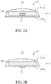
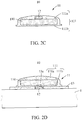
- FIGS. 2A through 2D are cross-sectional views of the capsule-type fire extinguisher 10 according to an example embodiment.
- FIG. 3 is a schematic diagram illustrating a forced exhaust 12 of the capsule-type fire extinguisher 10 according to an example embodiment.
- FIG. 4 is a diagram illustrating an operation of the capsule-type fire extinguisher 10 according to an example embodiment.
- the capsule-type fire extinguisher 10 includes an extinguishing capsule 11 configured to accommodate therein an extinguishing material 110, a fixing member 13 configured to fix the extinguishing capsule 11 to the battery 1, and the forced exhaust 12 configured to destroy the extinguishing capsule 11 and the battery 1.
- the extinguishing material 110 may be a material configured to extinguish a fire by being vaporized when it is heated to a predetermined temperature or higher.
- the extinguishing material 110 may be in a state of liquid or powder.
- the extinguishing capsule 11 is configured to externally discharge the extinguishing material 110 when the extinguishing material 110 is vaporized at the temperature or higher and thus expanded and ruptured.
- a shape of the extinguishing capsule 11 is not limited to the illustrated shape. However, it is possible to change the shape and the size of the extinguishing capsule 11 according to an environment where it is used and installed.
- the fixing member 13 is configured to attach the extinguishing capsule 11 to the battery 1.
- the fixing member 13 may be formed with a metal or polymer material, and a non-flammable or flame-retardant material.
- the fixing member 13 has a shape corresponding to a surface of the extinguishing capsule 11 to which the fixing member 13 is fixed, and has a band shape, for example.
- the shape of the fixing member 13 is not limited to the illustrated shape.
- the forced exhaust 12 is disposed on one side of the extinguishing capsule 11, and configured to destroy at least one of the extinguishing capsule 11 or the battery 1.
- the forced exhaust 12 may destroy the extinguishing capsule 11 or the battery 1, or both the extinguishing capsule 11 and the battery 1.
- the forced exhaust 12 may be disposed inside or outside the extinguishing capsule 11, or disposed between the extinguishing capsule 11 and the battery 1.
- the forced exhaust 12 may be disposed inside the extinguishing capsule 11.
- the forced exhaust 12 may be disposed at a position close to a wall 111 of the extinguishing capsule 11 to destroy the extinguishing capsule 11 by being disposed inside the extinguishing capsule 11.
- the forced exhaust 12 is illustrated as being disposed at a position close to a rear side 111b of the extinguishing capsule 11, it may be disposed at a position close to a surface side 111a or to a side surface.
- the forced exhaust 12 may be disposed on the rear side 111b of the extinguishing capsule 11, for example, a surface on which it is disposed on a side of the battery 1.
- the forced exhaust 12 may be disposed on an outer side of the wall 111 on the rear side 111b of the extinguishing capsule 11, or at least a portion of the forced exhaust 12 may be inserted into an inner side of the wall 111 or pass through the wall 111.
- the forced exhaust 12 may be disposed on the surface side 111a of the extinguishing capsule 11, for example, a surface of the extinguishing capsule 11 that is opposite to the rear side 111b.
- the forced exhaust 12 may be disposed on an outer side of the wall 111 on the surface side 111a of the extinguishing capsule 11, or at least a portion of the forced exhaust 12 may be inserted into an inner side of the wall 111 or pass through the wall 111.
- the forced exhaust 12 may be disposed in the fixing member 13.
- a groove 13a may be formed at a position in the fixing member 13 between the extinguishing capsule 11 and the battery 1, and the forced exhaust 12 may be disposed in the groove 13a, thereby being capable of destroying at least one of the extinguishing capsule 11 or the battery 1.
- the forced exhaust 12 includes a protrusion 121 to destroy the extinguishing capsule 11 or the battery 1, and a support frame 122 configured to press the protrusion 121 selectively toward the extinguishing capsule 11 or the battery 1.
- the forced exhaust 12 may be formed with at least one material of a bimetallic metal, a shape-memory alloy, or a plastic material by which the shape of the support frame 122 is at least deformed by an electrical signal or heat. That is, as the support frame 122 is deformed by an electrical signal or heat, the protrusion 121 may be pressed toward the extinguishing capsule 11 and the battery 1, and thus the forced exhaust 12 may destroy at least one of the extinguishing capsule 11 or the battery 1.
- the forced exhaust 12 may be disposed between the extinguishing capsule 11 and the battery 1, and the protrusion 121 may be disposed in both directions such that the forced exhaust 12 destroys both the extinguishing capsule 11 and the battery 1.
- the forced exhaust 12 may apply an impact to the battery 1 to prevent the battery 1 from being expanded, thereby preventing an explosion.
- the forced exhaust 12 may destroy the extinguishing capsule 11 to discharge the extinguishing material 110, thereby preventing the occurrence of a fire or extinguishing the fire.
- the protrusion 121 may be formed to allow the forced exhaust 12 to destroy the extinguishing capsule 11 or the battery 1.
- the forced exhaust 12 further includes an elastic support 123 configured to apply an elastic force to the support frame 122.
- the capsule-type fire extinguisher 10 may also be applied to the battery 1 which includes a plurality of unit cells 1a.
- the battery 1 includes a plurality of unit cells 1a and a housing 100 configured to accommodate therein the unit cells 1a.
- the battery 1 is simply illustrated with other components omitted, except the unit cells 1a.
- Each of the unit cells 1a includes the capsule-type fire extinguisher 10.
- the capsule-type fire extinguishers 10 respectively provided in the unit cells 1a may be independently provided, or be connected through a feeding pipe 102 configured to supply the extinguishing material 110.
- the battery 1 includes a feeding tank 101 configured to supply the extinguishing material 110 to the feeding pipe 102.
- the capsule-type fire extinguisher 10 may be provided in each of the unit cells 1a and the feeding pipe 102.
- a position and an operation of the capsule-type fire extinguisher 10 provided in each of the unit cells 1a are the same as described above with reference to FIGS. 1 through 4 . That is, the capsule-type fire extinguisher 10 may be provided on one side of each extinguishing capsule 11 and destroy at least one of each extinguishing capsule 11 and/or each unit cell 1a. Thus, a more detailed and repeated description of the capsule-type fire extinguisher 10 will be omitted here for brevity.
- the forced exhaust 12 may also be provided in the feeding pipe 102.
- the forced exhaust 12 provided in the feeding pipe 102 may be formed in the same way as the forced exhaust 12 is formed in each unit cell 1a.
- the forced exhaust 12 may be formed by including the support frame 122 formed with at least one material of a bimetallic metal, a shape-memory alloy, or a plastic material of which a shape is deformed by an electrical signal or heat, and the protrusion 121 formed by protruding from the support frame 122.
- the forced exhaust 12 may be deformed in shape by an electrical signal or heat, thereby destroying the feeding pipe 102.
- the forced exhaust 12 may apply an impact to the unit cell 1a and the extinguishing capsule 11 provided in the unit cell 1a, thereby destroying at least one of the unit cell 1a or the extinguishing capsule 11 to prevent the expansion of the unit cell 1a and prevent an explosion.
- the extinguishing material 110 discharged from the extinguishing capsule 11 may prevent the occurrence of a fire and extinguish the fire.
- by applying an electrical signal it is possible to operate the forced exhaust 12 provided in the unit cell 1a.
- a temperature of the feeding pipe 102 around the unit cell 1a may also increase to the predetermined temperature or higher, and thus the forced exhaust 12 provided in the feeding pipe 102 may operate to destroy the feeding pipe 102 and the extinguishing material 110 may be discharged.
- an electrical signal may be generated to operate simultaneously the forced exhaust 12 provided in the unit cell 1a and the forced exhaust 12 provided in the feeding pipe 102.
- the capsule-type fire extinguisher 10 may include the extinguishing capsule 11 including therein the extinguishing material 110 configured to expand at a predetermined temperature or higher, and may thus be small in size and simple in structure.
- the extinguishing capsule 11 may be destroyed by the extinguishing material 110, and also the forced exhaust 12 may also forcibly destroy the extinguishing capsule 11 and the battery 1 by an electrical signal or heat.
- the battery 1 may be effectively prevent an explosion of the battery 1.
- a capsule-type fire extinguisher may be included in a battery, and prevent an explosion of the battery by destroying at least one of an extinguishing capsule or the battery.
- the capsule-type fire extinguisher may include the extinguishing capsule of a capsule type that is configured to accommodate therein an extinguishing material, and is small in size and simple in structure. Thus, it is easy to change the shape and the size of the capsule-type fire extinguisher according to an environment where it is used and installed.
- the extinguishing capsule may be automatically destroyed by the evaporation of the extinguishing material at a preset temperature or higher, and the extinguishing capsule and the battery may also be forcibly destroyed by an electrical signal or heat.
- the extinguishing capsule and the battery may also be forcibly destroyed by an electrical signal or heat.
Landscapes
- Health & Medical Sciences (AREA)
- Public Health (AREA)
- Business, Economics & Management (AREA)
- Emergency Management (AREA)
- Chemical & Material Sciences (AREA)
- Chemical Kinetics & Catalysis (AREA)
- Electrochemistry (AREA)
- General Chemical & Material Sciences (AREA)
- Engineering & Computer Science (AREA)
- Manufacturing & Machinery (AREA)
- Battery Mounting, Suspending (AREA)
- Secondary Cells (AREA)
Abstract
Description
- One or more example embodiments relate to a capsule-type fire extinguisher for preventing an explosion of a battery, and a battery including the fire extinguisher.
- The recent development of electric vehicles, energy storage batteries, robots, satellites, or the like has spurred the research on high-performance secondary batteries capable of being charged or discharged repeatedly. In addition, there is also ongoing research on battery packs having the capacity and output power increased by connecting a plurality of secondary batteries in parallel or in series.
- In a case of a high-performance and high-capacity battery pack, there is a risk of a fire and an explosion due to an overcharge and an overcurrent. To detect a potential risk of a fire and an explosion, a temperature sensor, a current sensor, a voltage sensor, and the like are used for the battery pack. In addition, to extinguish a fire when the fire is detected, a fire extinguisher is installed separately from the battery pack. However, in such a case where the fire extinguisher is installed separately from the battery pack, it may be complicated to install the fire extinguisher and not be easy to detect such a potential risk and a fire. In addition, once a fire occurs from an explosion of a battery, there may be a great deal of damage. Thus, there is a growing need for a fire extinguisher to prevent a fire and an explosion in an initial state before the fire and the explosion occurs in a battery.
- Thus, there is a desire for a fire extinguisher that is installed in a battery in a simple and easy way and configured to prevent a fire or an explosion occurring when the battery expands by heat.
- The above description has been possessed or acquired by the inventor(s) in the course of conceiving the present disclosure and is not necessarily an art publicly known before the present application is filed.
- An aspect provides a capsule-type fire extinguisher for preventing a battery explosion, and a battery including the fire extinguisher.
- According to an example embodiment, there is provided a capsule-type fire extinguisher for preventing an explosion of a battery.
- The capsule-type fire extinguisher may include an extinguishing capsule including an extinguishing material configured to extinguish a fire by being externally discharged as being expanded and exploded by external heat in an inside thereof, a fixing member configured to fix the extinguishing capsule to the battery, and a forced exhaust provided on one side of the extinguishing capsule and configured to destroy at least one of the extinguishing capsule or the battery.
- The forced exhaust may be formed with at least one material of a bimetallic metal, a shape-memory alloy, or a plastic material of which a shape is deformed by an electrical signal or heat.
- The forced exhaust may include a support frame formed with at least one material of a bimetallic metal, a shape-memory alloy, or a plastic material of which a shape is deformed by an electrical signal or heat, and a protrusion formed by protruding from at least one side of the support frame. As a shape of the support frame is deformed by an electrical signal or heat, the support frame may press toward at least one side of the extinguishing capsule or the battery. The forced exhaust may further include an elastic support configured to elastically support the support frame. The forced exhaust may be disposed inside the extinguishing capsule or outside the extinguishing capsule. Alternatively, the forced exhaust may be disposed between the extinguishing capsule and the battery. The protrusion may be disposed on both directions such that the forced exhaust destroys both the extinguishing capsule and the battery.
- The forced exhaust may be inserted into the fixing member to be disposed between the extinguishing capsule and the battery.
- The fixing member may include a metal or polymer and be formed with a non-flammable and flame-retardant material.
- According to another example embodiment, there is provided a battery including a capsule-type fire extinguisher. The battery may include a plurality of unit cells, and a plurality of capsule-type fire extinguishers respectively provided in the unit cells. Each of the capsule-type fire extinguishers may include an extinguishing capsule including an extinguishing material configured to extinguish a fire by being externally discharged as being expanded and exploded by external heat in an inside thereof, and a forced exhaust provided on one side of the extinguishing capsule and configured to destroy at least one of the extinguishing capsule or a corresponding unit cell.
- The battery may further include a feeding pipe connected to each extinguishing capsule, and the forced exhaust may also be provided in the feeding pipe.
- The forced exhaust may be formed with at least one material of a bimetallic metal, a shape-memory alloy, or a plastic material of which a shape is deformed by an electrical signal or heat. The forced exhaust may include a support frame formed with at least one material of a bimetallic metal, a shape-memory alloy, or a plastic material of which a shape is deformed by an electrical signal or heat, and a protrusion formed by protruding from at least one side of the support frame.
- The forced exhaust may be disposed inside the extinguishing capsule or between the extinguishing capsule and the corresponding unit cell. Each of the capsule-type fire extinguishers may further include a fixing member configured to fix the extinguishing capsule to the corresponding unit cell. The fixing member may include a metal or polymer and be formed with a non-flammable and flame-retardant material. The forced exhaust may be inserted into the fixing member to be disposed between the extinguishing capsule and the unit cell.
- Additional aspects of example embodiments will be set forth in part in the description which follows and, in part, will be apparent from the description, or may be learned by practice of the disclosure.
- These and/or other aspects, features, and advantages of the present disclosure will become apparent and more readily appreciated from the following description of example embodiments, taken in conjunction with the accompanying drawings of which:
-
FIG. 1 is a front view of an example of a battery to which a capsule-type fire extinguisher is attached according to an example embodiment; -
FIGS. 2A through 2D are cross-sectional views of a capsule-type fire extinguisher according to an example embodiment; -
FIG. 3 is a schematic diagram illustrating a forced exhaust of a capsule-type fire extinguisher according to an example embodiment; -
FIG. 4 is a diagram illustrating an operation of a capsule-type fire extinguisher according to an example embodiment; and -
FIG. 5 is a diagram illustrating another example of a battery to which a capsule-type fire extinguisher is applied according to an example embodiment. - Hereinafter, example embodiments will be described in detail with reference to the accompanying drawings. It should be understood, however, that there is no intent to limit this disclosure to the particular example embodiments disclosed. On the contrary, example embodiments are to cover all modifications, equivalents, and alternatives falling within the scope of the example embodiments.
- The terminology used herein is for the purpose of describing particular example embodiments only and is not intended to be limiting. As used herein, the singular forms "a," "an," and "the," are intended to include the plural forms as well, unless the context clearly indicates otherwise. It will be further understood that the terms "comprises," "comprising," "includes," and/or "including," when used herein, specify the presence of stated features, integers, steps, operations, elements, and/or components, but do not preclude the presence or addition of one or more other features, integers, steps, operations, elements, components, and/or groups thereof. In addition, terms such as first, second, A, B, (a), (b), and the like may be used herein to describe components. Each of these terminologies is not used to define an essence, order, or sequence of a corresponding component but used merely to distinguish the corresponding component from other component(s). It should be noted that if it is described in the specification that one component is "connected," "coupled," or "joined" to another component, a third component may be "connected," "coupled," and "joined" between the first and second components, although the first component may be directly connected, coupled or joined to the second component.
- Hereinafter, example embodiments will be described in detail with reference to the accompanying drawings. In the description of example embodiments, detailed description of well-known related structures or functions will be omitted when it is deemed that such description will cause ambiguous interpretation of the present disclosure. Regarding the reference numerals assigned to the elements in the drawings, it should be noted that the same elements will be designated by the same reference numerals, wherever possible, even though they are shown in different drawings.
- Hereinafter, a capsule-
type fire extinguisher 10 according to an example embodiment will be described with reference toFIGS. 1 through 4 . -
FIG. 1 is a front view of abattery 1 to which the capsule-type fire extinguisher 10 is attached according to an example embodiment.FIGS. 2A through 2D are cross-sectional views of the capsule-type fire extinguisher 10 according to an example embodiment.FIG. 3 is a schematic diagram illustrating a forcedexhaust 12 of the capsule-type fire extinguisher 10 according to an example embodiment.FIG. 4 is a diagram illustrating an operation of the capsule-type fire extinguisher 10 according to an example embodiment. - Referring to the accompanying drawings, the capsule-
type fire extinguisher 10 includes an extinguishingcapsule 11 configured to accommodate therein an extinguishingmaterial 110, a fixingmember 13 configured to fix the extinguishingcapsule 11 to thebattery 1, and the forcedexhaust 12 configured to destroy the extinguishingcapsule 11 and thebattery 1. - The extinguishing
material 110 may be a material configured to extinguish a fire by being vaporized when it is heated to a predetermined temperature or higher. The extinguishingmaterial 110 may be in a state of liquid or powder. - The extinguishing
capsule 11 is configured to externally discharge the extinguishingmaterial 110 when the extinguishingmaterial 110 is vaporized at the temperature or higher and thus expanded and ruptured. A shape of the extinguishingcapsule 11 is not limited to the illustrated shape. However, it is possible to change the shape and the size of the extinguishingcapsule 11 according to an environment where it is used and installed. - The fixing
member 13 is configured to attach the extinguishingcapsule 11 to thebattery 1. For example, the fixingmember 13 may be formed with a metal or polymer material, and a non-flammable or flame-retardant material. In addition, the fixingmember 13 has a shape corresponding to a surface of the extinguishingcapsule 11 to which the fixingmember 13 is fixed, and has a band shape, for example. However, the shape of the fixingmember 13 is not limited to the illustrated shape. - The forced
exhaust 12 is disposed on one side of the extinguishingcapsule 11, and configured to destroy at least one of the extinguishingcapsule 11 or thebattery 1. For example, the forcedexhaust 12 may destroy the extinguishingcapsule 11 or thebattery 1, or both the extinguishingcapsule 11 and thebattery 1. To this end, the forcedexhaust 12 may be disposed inside or outside the extinguishingcapsule 11, or disposed between the extinguishingcapsule 11 and thebattery 1. - As illustrated in
FIG. 2A , the forcedexhaust 12 may be disposed inside the extinguishingcapsule 11. In such a case, the forcedexhaust 12 may be disposed at a position close to awall 111 of the extinguishingcapsule 11 to destroy the extinguishingcapsule 11 by being disposed inside the extinguishingcapsule 11. Although the forcedexhaust 12 is illustrated as being disposed at a position close to arear side 111b of the extinguishingcapsule 11, it may be disposed at a position close to asurface side 111a or to a side surface. - As illustrated in
FIG. 2B , the forcedexhaust 12 may be disposed on therear side 111b of the extinguishingcapsule 11, for example, a surface on which it is disposed on a side of thebattery 1. In addition, the forcedexhaust 12 may be disposed on an outer side of thewall 111 on therear side 111b of the extinguishingcapsule 11, or at least a portion of the forcedexhaust 12 may be inserted into an inner side of thewall 111 or pass through thewall 111. - Alternatively, as illustrated in
FIG. 2C , the forcedexhaust 12 may be disposed on thesurface side 111a of the extinguishingcapsule 11, for example, a surface of the extinguishingcapsule 11 that is opposite to therear side 111b. Similarly, the forcedexhaust 12 may be disposed on an outer side of thewall 111 on thesurface side 111a of the extinguishingcapsule 11, or at least a portion of the forcedexhaust 12 may be inserted into an inner side of thewall 111 or pass through thewall 111. - Alternatively, as illustrated in
FIG. 2D , the forcedexhaust 12 may be disposed in the fixingmember 13. Agroove 13a may be formed at a position in the fixingmember 13 between the extinguishingcapsule 11 and thebattery 1, and the forcedexhaust 12 may be disposed in thegroove 13a, thereby being capable of destroying at least one of the extinguishingcapsule 11 or thebattery 1. - The forced
exhaust 12 includes aprotrusion 121 to destroy the extinguishingcapsule 11 or thebattery 1, and asupport frame 122 configured to press theprotrusion 121 selectively toward the extinguishingcapsule 11 or thebattery 1. - The forced
exhaust 12 may be formed with at least one material of a bimetallic metal, a shape-memory alloy, or a plastic material by which the shape of thesupport frame 122 is at least deformed by an electrical signal or heat. That is, as thesupport frame 122 is deformed by an electrical signal or heat, theprotrusion 121 may be pressed toward the extinguishingcapsule 11 and thebattery 1, and thus the forcedexhaust 12 may destroy at least one of the extinguishingcapsule 11 or thebattery 1. - For example, as illustrated in
FIG. 4 , the forcedexhaust 12 may be disposed between the extinguishingcapsule 11 and thebattery 1, and theprotrusion 121 may be disposed in both directions such that the forcedexhaust 12 destroys both the extinguishingcapsule 11 and thebattery 1. In such a case, when thebattery 1 is expanded by heat, the forcedexhaust 12 may apply an impact to thebattery 1 to prevent thebattery 1 from being expanded, thereby preventing an explosion. In addition, by applying an impact to the extinguishingcapsule 11, the forcedexhaust 12 may destroy the extinguishingcapsule 11 to discharge the extinguishingmaterial 110, thereby preventing the occurrence of a fire or extinguishing the fire. - The
protrusion 121 may be formed to allow the forcedexhaust 12 to destroy the extinguishingcapsule 11 or thebattery 1. - The forced
exhaust 12 further includes anelastic support 123 configured to apply an elastic force to thesupport frame 122. - The example of the
battery 1 which is formed as a single cell has been described above. However, the capsule-type fire extinguisher 10 may also be applied to thebattery 1 which includes a plurality of unit cells 1a. - Referring to
FIG. 5 , thebattery 1 includes a plurality of unit cells 1a and ahousing 100 configured to accommodate therein the unit cells 1a. Thebattery 1 is simply illustrated with other components omitted, except the unit cells 1a. - Each of the unit cells 1a includes the capsule-
type fire extinguisher 10. - The capsule-
type fire extinguishers 10 respectively provided in the unit cells 1a may be independently provided, or be connected through afeeding pipe 102 configured to supply the extinguishingmaterial 110. In addition, thebattery 1 includes afeeding tank 101 configured to supply the extinguishingmaterial 110 to thefeeding pipe 102. - The capsule-
type fire extinguisher 10 may be provided in each of the unit cells 1a and thefeeding pipe 102. - A position and an operation of the capsule-
type fire extinguisher 10 provided in each of the unit cells 1a are the same as described above with reference toFIGS. 1 through 4 . That is, the capsule-type fire extinguisher 10 may be provided on one side of each extinguishingcapsule 11 and destroy at least one of each extinguishingcapsule 11 and/or each unit cell 1a. Thus, a more detailed and repeated description of the capsule-type fire extinguisher 10 will be omitted here for brevity. - The forced
exhaust 12 may also be provided in thefeeding pipe 102. The forcedexhaust 12 provided in thefeeding pipe 102 may be formed in the same way as the forcedexhaust 12 is formed in each unit cell 1a. - That is, the forced
exhaust 12 may be formed by including thesupport frame 122 formed with at least one material of a bimetallic metal, a shape-memory alloy, or a plastic material of which a shape is deformed by an electrical signal or heat, and theprotrusion 121 formed by protruding from thesupport frame 122. The forcedexhaust 12 may be deformed in shape by an electrical signal or heat, thereby destroying thefeeding pipe 102. - According to an example embodiment, when a unit cell 1a is heated to be a predetermined temperature or higher to be expanded, the forced
exhaust 12 may apply an impact to the unit cell 1a and the extinguishingcapsule 11 provided in the unit cell 1a, thereby destroying at least one of the unit cell 1a or the extinguishingcapsule 11 to prevent the expansion of the unit cell 1a and prevent an explosion. In addition, the extinguishingmaterial 110 discharged from the extinguishingcapsule 11 may prevent the occurrence of a fire and extinguish the fire. Alternatively, by applying an electrical signal, it is possible to operate the forcedexhaust 12 provided in the unit cell 1a. - In addition, when a unit cell 1a is heated to be a predetermined temperature or higher, a temperature of the
feeding pipe 102 around the unit cell 1a may also increase to the predetermined temperature or higher, and thus the forcedexhaust 12 provided in thefeeding pipe 102 may operate to destroy thefeeding pipe 102 and the extinguishingmaterial 110 may be discharged. - Alternatively, when the unit cell 1a is heated to be the predetermined temperature or higher, an electrical signal may be generated to operate simultaneously the forced
exhaust 12 provided in the unit cell 1a and the forcedexhaust 12 provided in thefeeding pipe 102. - As described above, the capsule-
type fire extinguisher 10 may include the extinguishingcapsule 11 including therein the extinguishingmaterial 110 configured to expand at a predetermined temperature or higher, and may thus be small in size and simple in structure. Thus, it is possible to change the shape and the size of the capsule-type fire extinguisher 10 based on an environment where it is to be used and installed. In addition, the extinguishingcapsule 11 may be destroyed by the extinguishingmaterial 110, and also the forcedexhaust 12 may also forcibly destroy the extinguishingcapsule 11 and thebattery 1 by an electrical signal or heat. Thus, it is possible to effectively prevent an explosion of thebattery 1. - According to example embodiments described herein, a capsule-type fire extinguisher may be included in a battery, and prevent an explosion of the battery by destroying at least one of an extinguishing capsule or the battery.
- The capsule-type fire extinguisher may include the extinguishing capsule of a capsule type that is configured to accommodate therein an extinguishing material, and is small in size and simple in structure. Thus, it is easy to change the shape and the size of the capsule-type fire extinguisher according to an environment where it is used and installed.
- In addition, the extinguishing capsule may be automatically destroyed by the evaporation of the extinguishing material at a preset temperature or higher, and the extinguishing capsule and the battery may also be forcibly destroyed by an electrical signal or heat. Thus, it is possible to effectively prevent an explosion of the battery.
- Advantageous effects of the capsule-type fire extinguisher for preventing a battery explosion and the battery including the capsule-type fire extinguisher are not limited to the foregoing, and other effects not described in the foregoing may be understood by those skilled in the art from the description provided above.
- While this disclosure includes specific examples, it will be apparent to one of ordinary skill in the art that various changes in form and details may be made in these examples without departing from the spirit and scope of the claims and their equivalents. The examples described herein are to be considered in a descriptive sense only, and not for purposes of limitation. Descriptions of features or aspects in each example are to be considered as being applicable to similar features or aspects in other examples. Suitable results may be achieved if the described techniques are performed in a different order, and/or if components in a described system, architecture, device, or circuit are combined in a different manner, and/or replaced or supplemented by other components or their equivalents.
- Therefore, the scope of the disclosure is defined not by the detailed description, but by the claims and their equivalents, and all variations within the scope of the claims and their equivalents are to be construed as being included in the disclosure.
Claims (15)
- A capsule-type fire extinguisher for preventing an explosion of a battery, comprising:an extinguishing capsule comprising an extinguishing material configured to extinguish a fire by being externally discharged as being expanded and exploded by external heat in an inside thereof;a fixing member configured to fix the extinguishing capsule to the battery; anda forced exhaust provided on one side of the extinguishing capsule and configured to destroy at least one of the extinguishing capsule or the battery.
- The capsule-type fire extinguisher of claim 1, wherein the forced exhaust is formed with at least one material of a bimetallic metal, a shape-memory alloy, or a plastic material of which a shape is deformed by an electrical signal or heat.
- The capsule-type fire extinguisher of claim 2, wherein the forced exhaust comprises:a support frame formed with at least one material of a bimetallic metal, a shape-memory alloy, or a plastic material of which a shape is deformed by an electrical signal or heat; anda protrusion formed by protruding from at least one side of the support frame,
wherein, as a shape of the support frame is deformed by an electrical signal or heat, the support frame is configured to press toward at least one side of the extinguishing capsule or the battery. - The capsule-type fire extinguisher of claim 3, wherein the forced exhaust further comprises:
an elastic support configured to elastically support the support frame. - The capsule-type fire extinguisher of claim 3, wherein the forced exhaust is disposed between the extinguishing capsule and the battery.
- The capsule-type fire extinguisher of claim 5, wherein the protrusion is disposed on both directions such that the forced exhaust destroys both the extinguishing capsule and the battery.
- The capsule-type fire extinguisher of claim 3, wherein the forced exhaust is inserted into the fixing member to be disposed between the extinguishing capsule and the battery.
- The capsule-type fire extinguisher of claim 1, wherein the fixing member comprises a metal or polymer and is formed with a non-flammable and flame-retardant material.
- A battery comprising a capsule-type fire extinguisher, comprising:a plurality of unit cells; anda plurality of capsule-type fire extinguishers respectively provided in the unit cells,
wherein each of the capsule-type fire extinguishers comprises:an extinguishing capsule comprising an extinguishing material configured to extinguish a fire by being externally discharged as being expanded and exploded by external heat in an inside thereof; anda forced exhaust provided on one side of the extinguishing capsule and configured to destroy at least one of the extinguishing capsule or a corresponding unit cell. - The battery of claim 9, further comprising:a feeding pipe connected to each extinguishing capsule,wherein the forced exhaust is also provided in the feeding pipe.
- The battery of claim 9, wherein the forced exhaust is formed with at least one material of a bimetallic metal, a shape-memory alloy, or a plastic material of which a shape is deformed by an electrical signal or heat.
- The battery of claim 11, wherein the forced exhaust comprises:a support frame formed with at least one material of a bimetallic metal, a shape-memory alloy, or a plastic material of which a shape is deformed by an electrical signal or heat; anda protrusion formed by protruding from at least one side of the support frame.
- The battery of claim 11, wherein the forced exhaust is disposed inside the extinguishing capsule or between the extinguishing capsule and a corresponding unit cell.
- The battery of claim 11, wherein each of the capsule-type fire extinguishers further comprises:a fixing member configured to fix the extinguishing capsule to a corresponding unit cell,wherein the fixing member comprises a metal or polymer and is formed with a non-flammable and flame-retardant material.
- The battery of claim 14, wherein the forced exhaust is inserted into the fixing member to be disposed between the extinguishing capsule and the unit cell.
Applications Claiming Priority (1)
| Application Number | Priority Date | Filing Date | Title |
|---|---|---|---|
| KR1020190108651A KR102295232B1 (en) | 2019-09-03 | 2019-09-03 | Capsule type fire extinguisher for preventing battery explosion and battery having the fire extinguisher |
Publications (2)
| Publication Number | Publication Date |
|---|---|
| EP3789088A1 true EP3789088A1 (en) | 2021-03-10 |
| EP3789088B1 EP3789088B1 (en) | 2025-11-05 |
Family
ID=72355829
Family Applications (1)
| Application Number | Title | Priority Date | Filing Date |
|---|---|---|---|
| EP20194245.5A Active EP3789088B1 (en) | 2019-09-03 | 2020-09-03 | Capsule type fire extinguisher for preventing battery explosion and battery having the fire extinguisher |
Country Status (5)
| Country | Link |
|---|---|
| US (1) | US20210060369A1 (en) |
| EP (1) | EP3789088B1 (en) |
| JP (1) | JP6999762B2 (en) |
| KR (1) | KR102295232B1 (en) |
| CN (1) | CN112448071A (en) |
Cited By (2)
| Publication number | Priority date | Publication date | Assignee | Title |
|---|---|---|---|---|
| EP4366058A4 (en) * | 2022-07-01 | 2025-09-10 | Lg Energy Solution Ltd | BATTERY MODULE WITH CARTRIDGE FOR FIRE EXTINGUISHING |
| EP4631581A1 (en) * | 2024-04-09 | 2025-10-15 | Samsung Sdi Co., Ltd. | Battery pack fire extinguisher |
Families Citing this family (10)
| Publication number | Priority date | Publication date | Assignee | Title |
|---|---|---|---|---|
| KR102660873B1 (en) * | 2021-10-29 | 2024-04-25 | 주식회사 엘지에너지솔루션 | Battery pack with improved safety |
| CN114069167B (en) * | 2022-01-18 | 2022-06-07 | 江苏时代新能源科技有限公司 | Secondary battery, battery module, battery pack, and electric device |
| CN114788938B (en) * | 2022-03-31 | 2023-01-06 | 江西新威动力能源科技有限公司 | Quick-response power battery fire extinguishing device |
| CN115531770B (en) * | 2022-03-31 | 2023-08-08 | 江西新威动力能源科技有限公司 | A power battery fire extinguishing mechanism |
| CN114796935B (en) * | 2022-03-31 | 2023-02-17 | 江西新威动力能源科技有限公司 | Self-extinguishing power battery |
| KR102480020B1 (en) * | 2022-04-11 | 2022-12-22 | 주식회사 동명기업 | Battery locker for fire protection and initial suppression |
| KR102884322B1 (en) * | 2022-12-23 | 2025-11-11 | 주식회사 성우하이텍 | Self-extinguishing battery case and battery system including the same |
| KR102556108B1 (en) * | 2023-03-08 | 2023-07-18 | 주식회사 루나볼트 | Hard case Battery module system equipped with fire extinguishing films |
| KR102556107B1 (en) * | 2023-03-08 | 2023-07-18 | 주식회사 루나볼트 | Battery modules equipped with fire extinguishing films |
| KR20250071656A (en) | 2023-11-15 | 2025-05-22 | 한국생산기술연구원 | Fire suppression battery pack and manufacturing method thereof |
Citations (4)
| Publication number | Priority date | Publication date | Assignee | Title |
|---|---|---|---|---|
| EP2159894A1 (en) * | 2008-03-11 | 2010-03-03 | Panasonic Corporation | Power apparatus and electronic apparatus using the same |
| JP2010097836A (en) * | 2008-10-17 | 2010-04-30 | Panasonic Corp | Battery pack, electronic equipment using it as power source, and battery pack case |
| WO2013006121A1 (en) * | 2011-07-01 | 2013-01-10 | Autoliv Development Ab | A battery safety arrangement for a motor vehicle |
| CN207474524U (en) * | 2017-09-29 | 2018-06-08 | 郑州宇通客车股份有限公司 | A kind of vehicle and its battery case, battery modules, fire extinguishing component, fire extinguishment container |
Family Cites Families (15)
| Publication number | Priority date | Publication date | Assignee | Title |
|---|---|---|---|---|
| JP2002085577A (en) * | 2000-09-19 | 2002-03-26 | Grand Forum:Kk | Automatic fire extinguishing device |
| JP2004321442A (en) * | 2003-04-24 | 2004-11-18 | Hidenobu Wakamatsu | Fire extinguishing method and its fire extinguishing apparatus |
| KR100853618B1 (en) * | 2006-01-04 | 2008-08-25 | 주식회사 엘지화학 | Medium and large battery packs with safety devices |
| KR101121757B1 (en) * | 2007-11-07 | 2012-03-23 | 에스케이이노베이션 주식회사 | Safety Apparatus and Protection Method of secondary Battery for Electric Vehicle Using Switch |
| KR101097101B1 (en) * | 2009-12-29 | 2011-12-22 | 주식회사 루트제이드 | Secondary battery having exploding prevention device |
| JP5530882B2 (en) * | 2010-09-29 | 2014-06-25 | Necパーソナルコンピュータ株式会社 | Battery pack |
| DE102011075318A1 (en) * | 2011-05-05 | 2012-11-08 | Sb Limotive Company Ltd. | Battery housing for lithium-ion cells |
| KR101605936B1 (en) * | 2013-05-02 | 2016-03-23 | 주식회사 엘지화학 | Battery pack capable of releasing gas inside of pouch type battery cell |
| CN104064692B (en) * | 2014-02-18 | 2016-03-02 | 浙江超威创元实业有限公司 | With the lithium battery of extinguishing device |
| JP6409702B2 (en) * | 2015-07-17 | 2018-10-24 | 株式会社デンソー | Vehicle collision detection device and inspection method thereof |
| CN106159152A (en) * | 2016-08-30 | 2016-11-23 | 南通鼎鑫电池有限公司 | A kind of safety device preventing lithium battery to expand blast |
| JP2018085245A (en) * | 2016-11-24 | 2018-05-31 | 技術研究組合リチウムイオン電池材料評価研究センター | Short circuit test device for battery and short circuit test method for battery |
| KR101984817B1 (en) * | 2017-05-11 | 2019-05-31 | 주식회사 대경산전 | Automatic fire extinguishing systems for energy storage systems |
| JP2018206656A (en) * | 2017-06-07 | 2018-12-27 | アクソンデータマシン株式会社 | Engine start assist device |
| JP3215506U (en) * | 2017-12-22 | 2018-03-29 | 潔 石原 | Fire extinguisher |
-
2019
- 2019-09-03 KR KR1020190108651A patent/KR102295232B1/en active Active
-
2020
- 2020-08-31 US US17/007,685 patent/US20210060369A1/en not_active Abandoned
- 2020-09-01 CN CN202010903471.9A patent/CN112448071A/en active Pending
- 2020-09-03 JP JP2020148116A patent/JP6999762B2/en active Active
- 2020-09-03 EP EP20194245.5A patent/EP3789088B1/en active Active
Patent Citations (4)
| Publication number | Priority date | Publication date | Assignee | Title |
|---|---|---|---|---|
| EP2159894A1 (en) * | 2008-03-11 | 2010-03-03 | Panasonic Corporation | Power apparatus and electronic apparatus using the same |
| JP2010097836A (en) * | 2008-10-17 | 2010-04-30 | Panasonic Corp | Battery pack, electronic equipment using it as power source, and battery pack case |
| WO2013006121A1 (en) * | 2011-07-01 | 2013-01-10 | Autoliv Development Ab | A battery safety arrangement for a motor vehicle |
| CN207474524U (en) * | 2017-09-29 | 2018-06-08 | 郑州宇通客车股份有限公司 | A kind of vehicle and its battery case, battery modules, fire extinguishing component, fire extinguishment container |
Cited By (2)
| Publication number | Priority date | Publication date | Assignee | Title |
|---|---|---|---|---|
| EP4366058A4 (en) * | 2022-07-01 | 2025-09-10 | Lg Energy Solution Ltd | BATTERY MODULE WITH CARTRIDGE FOR FIRE EXTINGUISHING |
| EP4631581A1 (en) * | 2024-04-09 | 2025-10-15 | Samsung Sdi Co., Ltd. | Battery pack fire extinguisher |
Also Published As
| Publication number | Publication date |
|---|---|
| EP3789088B1 (en) | 2025-11-05 |
| KR102295232B1 (en) | 2021-08-31 |
| US20210060369A1 (en) | 2021-03-04 |
| JP2021037289A (en) | 2021-03-11 |
| JP6999762B2 (en) | 2022-01-19 |
| CN112448071A (en) | 2021-03-05 |
| KR20210027786A (en) | 2021-03-11 |
Similar Documents
| Publication | Publication Date | Title |
|---|---|---|
| EP3789088B1 (en) | Capsule type fire extinguisher for preventing battery explosion and battery having the fire extinguisher | |
| JP6804662B2 (en) | Battery module, battery pack including it and automobile | |
| JP7037009B2 (en) | Pouch-type secondary battery including electrode tab cutting device | |
| KR102365631B1 (en) | Battery module | |
| RU2468477C2 (en) | Accumulator battery of middle or large size of increased security | |
| CN210429895U (en) | Battery module with improved safety and battery pack including the same | |
| JP5857254B2 (en) | Battery module | |
| JP7371239B2 (en) | A battery module including an absorbing member, a battery rack including the same, and a power storage system | |
| CN102945942A (en) | Safety apparatus and protection method of secondary battery for electric vehicle using switch | |
| KR102932319B1 (en) | Battery Pack, Battery Rack Comprising The Same, And Power Storage System | |
| KR20170050926A (en) | A secondary battery, secondary battery charging system and secondary battery production method to prevent battery cell swelling by detecting a displacement of gas venting unit | |
| JP6479345B2 (en) | Secondary battery and secondary battery pack including the same | |
| JP7034405B2 (en) | Battery module, battery pack including it and automobile | |
| CN107710458B (en) | Electrode lead and secondary battery having the same | |
| CN114342164A (en) | Battery module, battery pack including the same, and vehicle | |
| CN110073517B (en) | Battery cells with improved safety | |
| JP2020501312A (en) | Battery module, battery pack including the same, and automobile | |
| CN108140762A (en) | Battery pack | |
| KR20150028073A (en) | Battery pack and inter-busbar applied for the same | |
| JP2024543722A (en) | Battery module containing fire extinguishing cartridges | |
| CN107871840A (en) | battery unit | |
| KR20170040629A (en) | Battery module and battery pack including the same | |
| KR102341404B1 (en) | Battery module | |
| KR20230133621A (en) | Battery pack and energy storage system including the same | |
| US9324991B2 (en) | High voltage battery for vehicles |
Legal Events
| Date | Code | Title | Description |
|---|---|---|---|
| PUAI | Public reference made under article 153(3) epc to a published international application that has entered the european phase |
Free format text: ORIGINAL CODE: 0009012 |
|
| STAA | Information on the status of an ep patent application or granted ep patent |
Free format text: STATUS: REQUEST FOR EXAMINATION WAS MADE |
|
| 17P | Request for examination filed |
Effective date: 20200903 |
|
| AK | Designated contracting states |
Kind code of ref document: A1 Designated state(s): AL AT BE BG CH CY CZ DE DK EE ES FI FR GB GR HR HU IE IS IT LI LT LU LV MC MK MT NL NO PL PT RO RS SE SI SK SM TR |
|
| AX | Request for extension of the european patent |
Extension state: BA ME |
|
| STAA | Information on the status of an ep patent application or granted ep patent |
Free format text: STATUS: EXAMINATION IS IN PROGRESS |
|
| 17Q | First examination report despatched |
Effective date: 20220720 |
|
| GRAP | Despatch of communication of intention to grant a patent |
Free format text: ORIGINAL CODE: EPIDOSNIGR1 |
|
| STAA | Information on the status of an ep patent application or granted ep patent |
Free format text: STATUS: GRANT OF PATENT IS INTENDED |
|
| INTG | Intention to grant announced |
Effective date: 20250508 |
|
| GRAS | Grant fee paid |
Free format text: ORIGINAL CODE: EPIDOSNIGR3 |
|
| GRAA | (expected) grant |
Free format text: ORIGINAL CODE: 0009210 |
|
| STAA | Information on the status of an ep patent application or granted ep patent |
Free format text: STATUS: THE PATENT HAS BEEN GRANTED |
|
| AK | Designated contracting states |
Kind code of ref document: B1 Designated state(s): AL AT BE BG CH CY CZ DE DK EE ES FI FR GB GR HR HU IE IS IT LI LT LU LV MC MK MT NL NO PL PT RO RS SE SI SK SM TR |
|
| REG | Reference to a national code |
Ref country code: CH Ref legal event code: F10 Free format text: ST27 STATUS EVENT CODE: U-0-0-F10-F00 (AS PROVIDED BY THE NATIONAL OFFICE) Effective date: 20251105 Ref country code: GB Ref legal event code: FG4D |
|
| REG | Reference to a national code |
Ref country code: DE Ref legal event code: R096 Ref document number: 602020061562 Country of ref document: DE |
|
| REG | Reference to a national code |
Ref country code: IE Ref legal event code: FG4D |
|
| REG | Reference to a national code |
Ref country code: NL Ref legal event code: MP Effective date: 20251105 |
|
| PG25 | Lapsed in a contracting state [announced via postgrant information from national office to epo] |
Ref country code: ES Free format text: LAPSE BECAUSE OF FAILURE TO SUBMIT A TRANSLATION OF THE DESCRIPTION OR TO PAY THE FEE WITHIN THE PRESCRIBED TIME-LIMIT Effective date: 20251105 |
|
| REG | Reference to a national code |
Ref country code: LT Ref legal event code: MG9D |
|
| PG25 | Lapsed in a contracting state [announced via postgrant information from national office to epo] |
Ref country code: NO Free format text: LAPSE BECAUSE OF FAILURE TO SUBMIT A TRANSLATION OF THE DESCRIPTION OR TO PAY THE FEE WITHIN THE PRESCRIBED TIME-LIMIT Effective date: 20260205 |
|
| PG25 | Lapsed in a contracting state [announced via postgrant information from national office to epo] |
Ref country code: AT Free format text: LAPSE BECAUSE OF FAILURE TO SUBMIT A TRANSLATION OF THE DESCRIPTION OR TO PAY THE FEE WITHIN THE PRESCRIBED TIME-LIMIT Effective date: 20251105 Ref country code: FI Free format text: LAPSE BECAUSE OF FAILURE TO SUBMIT A TRANSLATION OF THE DESCRIPTION OR TO PAY THE FEE WITHIN THE PRESCRIBED TIME-LIMIT Effective date: 20251105 Ref country code: HR Free format text: LAPSE BECAUSE OF FAILURE TO SUBMIT A TRANSLATION OF THE DESCRIPTION OR TO PAY THE FEE WITHIN THE PRESCRIBED TIME-LIMIT Effective date: 20251105 |
|
| REG | Reference to a national code |
Ref country code: AT Ref legal event code: MK05 Ref document number: 1853737 Country of ref document: AT Kind code of ref document: T Effective date: 20251105 |
|
| PG25 | Lapsed in a contracting state [announced via postgrant information from national office to epo] |
Ref country code: NL Free format text: LAPSE BECAUSE OF FAILURE TO SUBMIT A TRANSLATION OF THE DESCRIPTION OR TO PAY THE FEE WITHIN THE PRESCRIBED TIME-LIMIT Effective date: 20251105 |
|
| PG25 | Lapsed in a contracting state [announced via postgrant information from national office to epo] |
Ref country code: RS Free format text: LAPSE BECAUSE OF FAILURE TO SUBMIT A TRANSLATION OF THE DESCRIPTION OR TO PAY THE FEE WITHIN THE PRESCRIBED TIME-LIMIT Effective date: 20260205 |
|
| PG25 | Lapsed in a contracting state [announced via postgrant information from national office to epo] |
Ref country code: IS Free format text: LAPSE BECAUSE OF FAILURE TO SUBMIT A TRANSLATION OF THE DESCRIPTION OR TO PAY THE FEE WITHIN THE PRESCRIBED TIME-LIMIT Effective date: 20260305 |
|
| PG25 | Lapsed in a contracting state [announced via postgrant information from national office to epo] |
Ref country code: PT Free format text: LAPSE BECAUSE OF FAILURE TO SUBMIT A TRANSLATION OF THE DESCRIPTION OR TO PAY THE FEE WITHIN THE PRESCRIBED TIME-LIMIT Effective date: 20260305 |
|
| PG25 | Lapsed in a contracting state [announced via postgrant information from national office to epo] |
Ref country code: PL Free format text: LAPSE BECAUSE OF FAILURE TO SUBMIT A TRANSLATION OF THE DESCRIPTION OR TO PAY THE FEE WITHIN THE PRESCRIBED TIME-LIMIT Effective date: 20251105 |
|
| PG25 | Lapsed in a contracting state [announced via postgrant information from national office to epo] |
Ref country code: LV Free format text: LAPSE BECAUSE OF FAILURE TO SUBMIT A TRANSLATION OF THE DESCRIPTION OR TO PAY THE FEE WITHIN THE PRESCRIBED TIME-LIMIT Effective date: 20251105 |