EP3788866A2 - Electric lopper - Google Patents
Electric lopper Download PDFInfo
- Publication number
- EP3788866A2 EP3788866A2 EP20193986.5A EP20193986A EP3788866A2 EP 3788866 A2 EP3788866 A2 EP 3788866A2 EP 20193986 A EP20193986 A EP 20193986A EP 3788866 A2 EP3788866 A2 EP 3788866A2
- Authority
- EP
- European Patent Office
- Prior art keywords
- cutter
- electric
- casing
- drive mechanism
- lopper
- Prior art date
- Legal status (The legal status is an assumption and is not a legal conclusion. Google has not performed a legal analysis and makes no representation as to the accuracy of the status listed.)
- Pending
Links
Images




Classifications
-
- A—HUMAN NECESSITIES
- A01—AGRICULTURE; FORESTRY; ANIMAL HUSBANDRY; HUNTING; TRAPPING; FISHING
- A01G—HORTICULTURE; CULTIVATION OF VEGETABLES, FLOWERS, RICE, FRUIT, VINES, HOPS OR SEAWEED; FORESTRY; WATERING
- A01G3/00—Cutting implements specially adapted for horticultural purposes; Delimbing standing trees
- A01G3/02—Secateurs; Flower or fruit shears
- A01G3/033—Secateurs; Flower or fruit shears having motor-driven blades
- A01G3/037—Secateurs; Flower or fruit shears having motor-driven blades the driving means being an electric motor
-
- A—HUMAN NECESSITIES
- A01—AGRICULTURE; FORESTRY; ANIMAL HUSBANDRY; HUNTING; TRAPPING; FISHING
- A01G—HORTICULTURE; CULTIVATION OF VEGETABLES, FLOWERS, RICE, FRUIT, VINES, HOPS OR SEAWEED; FORESTRY; WATERING
- A01G3/00—Cutting implements specially adapted for horticultural purposes; Delimbing standing trees
- A01G3/02—Secateurs; Flower or fruit shears
- A01G3/025—Secateurs; Flower or fruit shears having elongated or extended handles
- A01G3/0255—Tree pruners, i.e. pruning shears carried at the end of a pole
-
- A—HUMAN NECESSITIES
- A01—AGRICULTURE; FORESTRY; ANIMAL HUSBANDRY; HUNTING; TRAPPING; FISHING
- A01G—HORTICULTURE; CULTIVATION OF VEGETABLES, FLOWERS, RICE, FRUIT, VINES, HOPS OR SEAWEED; FORESTRY; WATERING
- A01G3/00—Cutting implements specially adapted for horticultural purposes; Delimbing standing trees
- A01G3/02—Secateurs; Flower or fruit shears
- A01G3/033—Secateurs; Flower or fruit shears having motor-driven blades
- A01G3/0335—Secateurs; Flower or fruit shears having motor-driven blades having elongated or extended handles
Definitions
- the present invention relates to the technical field of outdoor tools, in particular to an electric lopper.
- a lopper is an outdoor tool that is commonly used for pruning all kinds of bushes and branches, etc., in gardens. Electric loppers are widely used on account of such characteristics as being lightweight, convenient to operate, safe and reliable.
- Existing electric loppers generally comprise a cutter set, wherein a lower cutter is fixed, and an upper cutter reciprocates up and down under the driving action of a drive means, in order to prune bushes and branches, etc.
- the drive means generally employs a bevel gear drive; in the process of transmission, vibration and noise levels are high, and operation is not smooth.
- the object of the present invention is to provide an electric lopper, for the purpose of increasing the smoothness of transmission in the electric lopper and reducing pruning noise from the electric lopper.
- the present invention provides an electric lopper, comprising a handle, a connecting pole and a pruning component which are connected in sequence, wherein the pruning component comprises a casing, a control mechanism and, connected in sequence, a motive power mechanism, a drive mechanism and a cutter set, wherein the motive power mechanism and the drive mechanism are disposed in the casing, the cutter set is disposed at that end of the casing which is remote from the motive power mechanism, a switch connected to the motive power mechanism is provided on the handle, and the control mechanism is connected to the drive mechanism; the drive mechanism is a worm gear/worm drive mechanism or a ball screw drive mechanism.
- a worm in the worm gear/worm drive mechanism is connected to the motive power mechanism, and a small gear is provided on the worm gear, the small gear transmitting motive power concentrically with the worm gear; the small gear is meshed with an upper cutter in the cutter set, and a lower cutter in the cutter set is connected to the upper cutter and fixed to the casing.
- the upper cutter comprises a toothed tail part and an upper cutting head which are connected to each other, wherein the toothed tail part is meshed with the small gear.
- the toothed tail part is of lower hardness than the upper cutting head.
- the toothed tail part, the upper cutting head and the lower cutter are connected together by means of a threaded connecting member.
- the threaded connecting member is a stepped connecting member, comprising a cylindrical threaded end, a cylindrical middle segment, a square prism and a cuboid end which are connected in sequence, wherein the cylindrical threaded end is arranged coaxially with the cylindrical middle segment, and the cylindrical threaded end has a smaller diameter than the cylindrical middle segment; the circle centre of a cross section of the cylindrical middle segment, the centre point of a square cross section of the square prism and the centre point of the cuboid end are all coincident; moreover, the area of the cross section of the cylindrical middle segment is less than the area of the square cross section of the square prism, and the area of the square cross section of the square prism is less than the area of that side of the cuboid end which is connected to the square prism; the toothed tail part and the upper cutting head are provided with round through-holes fitting the cylindrical middle segment, the lower cutter and the casing are provided with square through-holes fitting the square prism, and the cas
- control mechanism comprises a fixed pin disposed on the worm gear and, mounted on the casing, a direction change switch and a stop switch; the fixed pin touches the direction change switch as the worm gear rotates, the worm gear rotates in the opposite direction, the worm gear touches the stop switch while rotating in the opposite direction, and the worm gear stops rotating.
- the ball screw drive mechanism comprises a screw and a screw nut mounted on the screw, the screw being connected to the motive power mechanism, the screw nut being connected to an upper cutter in the cutter set, and a lower cutter in the cutter set being connected to the upper cutter and fixed to the casing.
- the screw nut is connected to the upper cutter by means of a forked connecting member.
- the forked connecting member is an integrally stamped forked connecting member.
- the forked connecting member is connected to the screw nut by means of a countersunk screw.
- two ends of the forked connecting member that are connected to the screw nut are arc-shaped ends.
- a sealing ring is provided between the forked connecting member and the casing.
- control mechanism comprises a Hall sensor connected to the screw nut, movement of the screw nut being controlled by means of the Hall sensor.
- the motive power mechanism comprises a DC motor and a planetary gear speed reducer, with an input end of the planetary gear speed reducer being connected to an output end of the DC motor, and an output end of the planetary gear speed reducer being connected to the drive mechanism.
- a power supply means supplying power to the DC motor is provided in the handle.
- the connecting pole is a telescopic connecting pole.
- the pruning component is connected to the connecting pole rotatably.
- the pruning component is connected to the connecting pole rotatably by means of a rotary button;
- the rotary button is a T-shaped button, a boss is provided along a side face of an upper end of the T-shaped button, and multiple protrusions are provided uniformly on the boss; an inside face, connected to the upper end, of the connecting pole is provided with multiple slots fitting the protrusions; and a mounting platform, provided with a slot fitting a lower end of the T-shaped button, is provided in the casing.
- the T-shaped button further comprises a spring, which passes through the lower end and is mounted between an inside face of the upper end and the mounting platform.
- the cutter set comprises at least one cutter made of at least two different materials.
- the at least one cutter comprises a connecting part made of a first material and a cutting part made of a second material.
- a characteristic thereof is that the first material is of lower hardness than the second material.
- the cutter set comprises a visibility enhancing feature.
- the visibility enhancing feature is selected from at least one of luminous features, highly reflective features, fluorescent features, brightly coloured features and pattern features.
- the visibility enhancing feature is provided on an outside surface of at least one cutter in the cutter set.
- the electric lopper provided in the present invention comprises a handle, a connecting pole and a pruning component which are connected in sequence, wherein the pruning component comprises a casing and, connected in sequence, a control mechanism, a motive power mechanism, a drive mechanism and a cutter set, wherein the motive power mechanism and the drive mechanism are disposed in the casing, the cutter set is disposed at that end of the casing which is remote from the motive power mechanism, a switch connected to the control mechanism is provided on the handle, and the drive mechanism is a worm gear/worm drive mechanism or a ball screw drive mechanism.
- the embodiments of the present invention provide an electric lopper, the electric lopper comprising a handle 1, a connecting pole 2 and a pruning component 3 which are connected in sequence.
- the pruning component 3 comprises a casing 31, a control mechanism 32 and, connected in sequence, a motive power mechanism 33, a drive mechanism and a cutter set, wherein the motive power mechanism 33 and drive mechanism are disposed in the casing 31, the cutter set is disposed at that end of the casing 31 which is remote from the motive power mechanism 33, a switch 4 connected to the motive power mechanism 33 is provided on the handle 1, and the control mechanism is connected to the drive mechanism;
- the drive mechanism is a worm gear/worm drive mechanism 34 or a ball screw drive mechanism 35.
- the switch 4 on the handle 1 is pressed, the motive power mechanism 33 is activated by means of the switch 4, and the motive power mechanism 33 transmits motive power to the worm gear/worm drive mechanism 34 or ball screw drive mechanism 35 connected thereto, thus activating the electric lopper, while travel control is achieved by means of the control mechanism 32 connected to the drive mechanism.
- the drive mechanism is the worm gear/worm drive mechanism 34 or ball screw drive mechanism 35; by using the worm gear/worm drive mechanism 34 or ball screw drive mechanism 35 to replace an existing bevel gear drive mechanism, it is possible not only to reduce noise during transmission but also to effectively increase the smoothness of transmission, thus greatly improving the performance of the electric lopper.
- the cutter set of the electric lopper may comprise at least one cutter made of at least two different materials.
- the at least one cutter may comprise a connecting part made of a first material and a cutting part made of a second material, and furthermore, the first material is of lower hardness than the second material, i.e. a second material of greater hardness is used to make the cutting part; thus, in the process of using the cutter to perform cutting, damage to the cutter due to stress concentration can be prevented while ensuring the cutting performance of the cutter, and also, separate replacement is possible when the cutting part or connecting part breaks, facilitating maintenance and reducing maintenance costs.
- the first material used to make the connecting part is of lower hardness, the wear experienced by a drive structure driving the connecting part to move can be effectively reduced, increasing the lifespan of the drive structure and thus increasing the service life of the electric lopper.
- the electric lopper employs a worm gear/worm drive; specifically, a worm 341 in the worm gear/worm drive mechanism 34 is connected to the motive power mechanism 33, and a small gear 343 is provided on a worm gear 342 in the worm drive mechanism 34, the small gear transmitting motive power concentrically with the worm gear 342; the small gear 343 is meshed with an upper cutter 36 in the cutter set, and a lower cutter 37 in the cutter set is connected to the upper cutter 36 and fixed to the casing 31.
- a worm gear/worm drive specifically, a worm 341 in the worm gear/worm drive mechanism 34 is connected to the motive power mechanism 33, and a small gear 343 is provided on a worm gear 342 in the worm drive mechanism 34, the small gear transmitting motive power concentrically with the worm gear 342; the small gear 343 is meshed with an upper cutter 36 in the cutter set, and a lower cutter 37 in the cutter set is connected to the upper cutter 36 and fixed to the casing 31.
- motive power outputted by the motive power mechanism 33 drives the worm 341 to rotate, and the small gear 343 on the worm gear 342 meshed with the worm 341 rotates with the worm gear 342, driving the upper cutter 36 meshed with the small gear to reciprocate up and down, cooperating with the lower cutter 37 to prune bushes, etc.
- the upper cutter 36 comprises a toothed tail part 361 and an upper cutting head 362 which are connected to each other, wherein the toothed tail part 361 is meshed with the small gear 343.
- motive power outputted by the motive power mechanism 33 drives the worm 341 to rotate, and the small gear 343 on the worm gear 342 meshed with the worm 341 rotates with the worm gear 342, and by means of the toothed tail part 361 meshed with the small gear, drives the upper cutting head 362 connected to the toothed tail part to reciprocate up and down, cooperating with the lower cutter 37 to prune bushes, etc.
- the toothed tail part 361 is of lower hardness than the upper cutting head 362.
- the small gear 343 is generally of lower hardness than the upper cutter 36 used for cutting, and consequently, in the process of using the electric lopper, the small gear 343 experiences severe wear, with the result that the lifespan of the electric lopper is short.
- the upper cutter 36 is divided into two parts: the upper cutting head 362 for pruning bushes and branches, etc., is of greater hardness, while the toothed tail part 361 used for transmission is of lower hardness, making it possible to effectively reduce wear to the small gear 343 due to friction of meshing with the tail part of the upper cutter 36, increasing the lifespan of the small gear 343, and thus increasing the service life of the electric lopper; in addition, by dividing the upper cutter 36 into two parts, it is possible to prevent cutter damage due to stress concentration, and also, separate replacement is possible when the toothed tail part 361 or upper cutting head 362 breaks, facilitating maintenance and reducing maintenance costs.
- the toothed tail part 361, upper cutting head 362 and lower cutter 37 are connected together by means of a threaded connecting member 38.
- the threaded connecting member 38 is a stepped connecting member, comprising a cylindrical threaded end 381, a cylindrical middle segment 382, a square prism 383 and a cuboid end 384 which are connected in sequence.
- the cylindrical threaded end 381 is arranged coaxially with the cylindrical middle segment 382, and the cylindrical threaded end 381 has a smaller diameter than the cylindrical middle segment 382; the circle centre of a cross section of the cylindrical middle segment 382, the centre point of a square cross section of the square prism 383 and the centre point of the cuboid end 384 are all coincident; moreover, the area of the cross section of the cylindrical middle segment 382 is less than the area of the square cross section of the square prism 383, and the area of the square cross section of the square prism 383 is less than the area of that side of the cuboid end 384 which is connected to the square prism 383.
- the toothed tail part 361 and upper cutting head 362 are provided with round through-holes fitting the cylindrical middle segment 382, the lower cutter 37 and casing 31 are provided with square through-holes fitting the square prism 383, and the casing 31 is provided with a rectangular recess fitting the cuboid end 384, the square through-hole in the casing 31 being disposed in the rectangular recess.
- the stepped connecting member passes through the casing 31, lower cutter 37, upper cutting head 362 and toothed tail part 361 in sequence; the cylindrical threaded end 381 passes through the toothed tail part 361 and is connected to a nut.
- the control mechanism 32 comprises a fixed pin 321 disposed on the worm gear 342 and, mounted on the casing 31, a direction change switch 322 and a stop switch 323.
- the fixed pin 321 touches the direction change switch 322 as the worm gear 342 rotates, the worm gear 342 rotates in the opposite direction, the worm gear 342 touches the stop switch 323 while rotating in the opposite direction, and the worm gear 342 stops rotating.
- the electric lopper employs a ball screw drive; specifically, the ball screw drive mechanism 35 comprises a screw 351 and a screw nut 352 mounted on the screw 351, the screw 351 being connected to the motive power mechanism 33, the screw nut 352 being connected to an upper cutter 36 in the cutter set, and a lower cutter 37 in the cutter set being connected to the upper cutter 36 and fixed to the casing 31.
- the ball screw drive mechanism 35 comprises a screw 351 and a screw nut 352 mounted on the screw 351, the screw 351 being connected to the motive power mechanism 33, the screw nut 352 being connected to an upper cutter 36 in the cutter set, and a lower cutter 37 in the cutter set being connected to the upper cutter 36 and fixed to the casing 31.
- motive power outputted by the motive power mechanism 33 is converted from rotational motion to linear motion via the screw 351 and screw nut 352, driving the screw nut 352 to reciprocate, and thus driving the upper cutter 36 connected to the screw nut 352 to reciprocate, cooperating with the lower cutter 37 to prune bushes, etc.
- the screw nut 352 is connected to the upper cutter 36 by means of a forked connecting member 39.
- the forked connecting member 39 provided in embodiments of the present invention is always one component, with strong integrity, and good structural strength, and being simple to fit, and can be made by stamping a sheet, at a low cost.
- the forked connecting member 39 is an integrally stamped forked connecting member, which does not require any welding and has better structural strength and load-bearing ability; where installation space allows, the forked connecting member 39 shown in fig. 10 may preferably be used.
- the forked connecting member 39 is connected to the screw nut 352 by means of countersunk screws 5; thus, the forked connecting member 39 can be effectively prevented from opening outwards when subjected to a force, and furthermore, when the upper cutter 36 completes one action of cutting and return, the countersunk screws 5 can bear the pulling force of the forked connecting member 39, increasing the stability of the electric lopper structure.
- two ends of the forked connecting member 39 that are connected to the screw nut 352 are arc-shaped ends; thus, an arc fit can be realized between the forked connecting member 39 and the screw nut 352, and when the electric lopper is cutting, the screw nut 352 can bear a greater pushing force, preventing the countersunk screws 5 from being pushed to destruction; moreover, relative rotation of the forked connecting member 39 around the centre of the arc is also possible, so the forked connecting member 39 will not be locked up.
- a sealing ring may also be provided between the forked connecting member 39 and the casing 31, to prevent the ingress of impurities and dust, etc., into the casing 31 from the surroundings, and consequent damage to the electric lopper.
- the casing 31 is further provided with a hooked structure 311 facing away from the lower cutter 37; thus, the hooked structure can be used to hook off branches, etc., that have been cut, avoiding a situation where branches that have been cut become hung on other branches.
- control mechanism 32 may comprise a Hall sensor connected to the screw nut 352; movement of the screw nut 352 is controlled by means of the Hall sensor, thereby controlling the travel of the electric lopper.
- a visibility enhancing feature is provided for the cutter set, thus enabling a user to clearly distinguish the relative positions of the cutters and the plant to be pruned during use.
- the visibility enhancing feature comprises various features that make the cutters easier for the user to see, such as luminous features, highly reflective features, fluorescent features, brightly coloured features and pattern features.
- the visibility enhancing feature may be provided to the cutter set in various ways.
- an additional material coating may be applied to the cutter set.
- the material coating is provided on an outside surface of at least one cutter in the cutter set.
- the material coating is provided on an outside surface of the lower cutter 37 in the cutter set.
- an additional visibility enhancing component may be provided for the cutter set, the visibility enhancing component being attached to one of the cutters in the cutter set.
- the visibility enhancing component has the abovementioned visibility enhancing feature.
- the motive power mechanism 33 may in each case comprise a DC motor 331 and a planetary gear speed reducer 332, with an input end of the planetary gear speed reducer 332 being connected to an output end of the DC motor 331, and an output end of the planetary gear speed reducer 332 being connected to the drive mechanism.
- the output end of the planetary gear speed reducer 332 is connected to the worm 341, or the output end of the planetary gear speed reducer 332 is connected to the screw 351, and motive power outputted by the DC motor 331 is transmitted to the worm gear/worm drive mechanism 34 or ball screw drive mechanism 35 after speed reduction by the planetary gear speed reducer 332.
- a power supply means supplying power to the DC motor 331 is provided in the handle 1.
- the DC motor 331 may be a brushless DC motor or a lower-cost brushed DC motor; the embodiments of the present invention do not impose any restriction in this respect.
- the connecting pole 2 may be a telescopic connecting pole.
- the connecting pole 2 may comprise an inner tube 21, an outer tube 22, and a locking means 23 fitted round the outer tube 22.
- the locking means 23 comprises a base 231, a first locking sleeve 232 fitted round the outer tube 22 in a fixed manner, a second locking sleeve 233 fitted round the inner tube 21 in a slideable manner, and a locking lever 234 mounted on the first locking sleeve 232 and second locking sleeve 233.
- the connecting pole 2 may comprise an inner tube, an outer tube, and a sleeve connected to the inner tube and outer tube; an inner surface of the sleeve that is connected to the outer tube, and an end outer surface of the outer tube that is connected to the sleeve, are provided with threads which mate with each other. After releasing the sleeve by turning, the user can freely slide the inner tube in the outer tube, pull out or push in the inner tube by a certain distance as required, and then tighten the sleeve by turning, to realize length adjustment of the connecting pole 2.
- the pruning component 3 is connected to the connecting pole 2 rotatably.
- the pruning component 3 is connected to the connecting pole 2 rotatably by means of a rotary button 6.
- the rotary button is a T-shaped button
- a boss 62 is provided along a side face of an upper end 61 of the T-shaped button, and multiple protrusions 63 are provided uniformly on the boss 62
- an inside face, connected to the upper end 61 of the T-shaped button, of the connecting pole 2 is provided with multiple slots fitting the protrusions 63
- the user presses the rotary button 6, and the protrusions 63 of the upper end 61 of the rotary button 6 will then disengage from the slots of the inside face, connected to the upper end 61 of the T-shaped button, of the connecting pole 2; at the same time, the lower end 64 remains mated with the mounting platform 312, and the rotary button 6 is fixed relative to the pruning component 3 but moveable relative to the connecting pole 2, so the pruning component 3 can be turned.
- the T-shaped button further comprises a spring 65, which passes through the lower end 64 and is mounted between an inside face of the upper end 61 and the mounting platform 312.
- the T-shaped button can be released; the spring 65 will automatically push up the T-shaped button, and the protrusions 63 will engage in the slots in the inside face, connected to the upper end 61 of the T-shaped button, of the connecting pole 2, locking the current angle of the pruning component 3.
Landscapes
- Life Sciences & Earth Sciences (AREA)
- Biodiversity & Conservation Biology (AREA)
- Ecology (AREA)
- Forests & Forestry (AREA)
- Environmental Sciences (AREA)
- Scissors And Nippers (AREA)
Abstract
Description
- The present invention relates to the technical field of outdoor tools, in particular to an electric lopper.
- A lopper is an outdoor tool that is commonly used for pruning all kinds of bushes and branches, etc., in gardens. Electric loppers are widely used on account of such characteristics as being lightweight, convenient to operate, safe and reliable.
- Existing electric loppers generally comprise a cutter set, wherein a lower cutter is fixed, and an upper cutter reciprocates up and down under the driving action of a drive means, in order to prune bushes and branches, etc. However, in existing electric loppers, the drive means generally employs a bevel gear drive; in the process of transmission, vibration and noise levels are high, and operation is not smooth.
- The object of the present invention is to provide an electric lopper, for the purpose of increasing the smoothness of transmission in the electric lopper and reducing pruning noise from the electric lopper.
- To achieve the abovementioned object, the present invention provides an electric lopper, comprising a handle, a connecting pole and a pruning component which are connected in sequence, wherein the pruning component comprises a casing, a control mechanism and, connected in sequence, a motive power mechanism, a drive mechanism and a cutter set, wherein the motive power mechanism and the drive mechanism are disposed in the casing, the cutter set is disposed at that end of the casing which is remote from the motive power mechanism, a switch connected to the motive power mechanism is provided on the handle, and the control mechanism is connected to the drive mechanism; the drive mechanism is a worm gear/worm drive mechanism or a ball screw drive mechanism.
- Optionally, a worm in the worm gear/worm drive mechanism is connected to the motive power mechanism, and a small gear is provided on the worm gear, the small gear transmitting motive power concentrically with the worm gear; the small gear is meshed with an upper cutter in the cutter set, and a lower cutter in the cutter set is connected to the upper cutter and fixed to the casing.
- Further optionally, the upper cutter comprises a toothed tail part and an upper cutting head which are connected to each other, wherein the toothed tail part is meshed with the small gear.
- Further optionally, the toothed tail part is of lower hardness than the upper cutting head.
- Optionally, the toothed tail part, the upper cutting head and the lower cutter are connected together by means of a threaded connecting member.
- Further optionally, the threaded connecting member is a stepped connecting member, comprising a cylindrical threaded end, a cylindrical middle segment, a square prism and a cuboid end which are connected in sequence, wherein the cylindrical threaded end is arranged coaxially with the cylindrical middle segment, and the cylindrical threaded end has a smaller diameter than the cylindrical middle segment; the circle centre of a cross section of the cylindrical middle segment, the centre point of a square cross section of the square prism and the centre point of the cuboid end are all coincident; moreover, the area of the cross section of the cylindrical middle segment is less than the area of the square cross section of the square prism, and the area of the square cross section of the square prism is less than the area of that side of the cuboid end which is connected to the square prism; the toothed tail part and the upper cutting head are provided with round through-holes fitting the cylindrical middle segment, the lower cutter and the casing are provided with square through-holes fitting the square prism, and the casing is provided with a rectangular recess fitting the cuboid end, the square through-hole in the casing being disposed in the rectangular recess;
starting at the cuboid end, the stepped connecting member passes through the casing, the lower cutter, the upper cutting head and the toothed tail part in sequence; the cylindrical threaded end passes through the toothed tail part and is connected to a nut. - Optionally, the control mechanism comprises a fixed pin disposed on the worm gear and, mounted on the casing, a direction change switch and a stop switch; the fixed pin touches the direction change switch as the worm gear rotates, the worm gear rotates in the opposite direction, the worm gear touches the stop switch while rotating in the opposite direction, and the worm gear stops rotating.
- Optionally, the ball screw drive mechanism comprises a screw and a screw nut mounted on the screw, the screw being connected to the motive power mechanism, the screw nut being connected to an upper cutter in the cutter set, and a lower cutter in the cutter set being connected to the upper cutter and fixed to the casing.
- Further optionally, the screw nut is connected to the upper cutter by means of a forked connecting member.
- Further optionally, the forked connecting member is an integrally stamped forked connecting member.
- Further optionally, the forked connecting member is connected to the screw nut by means of a countersunk screw.
- Further optionally, two ends of the forked connecting member that are connected to the screw nut are arc-shaped ends.
- Further optionally, a sealing ring is provided between the forked connecting member and the casing.
- Optionally, the control mechanism comprises a Hall sensor connected to the screw nut, movement of the screw nut being controlled by means of the Hall sensor.
- Optionally, the motive power mechanism comprises a DC motor and a planetary gear speed reducer, with an input end of the planetary gear speed reducer being connected to an output end of the DC motor, and an output end of the planetary gear speed reducer being connected to the drive mechanism.
- Optionally, a power supply means supplying power to the DC motor is provided in the handle.
- Optionally, the connecting pole is a telescopic connecting pole.
- Optionally, the pruning component is connected to the connecting pole rotatably.
- Further optionally, the pruning component is connected to the connecting pole rotatably by means of a rotary button; the rotary button is a T-shaped button, a boss is provided along a side face of an upper end of the T-shaped button, and multiple protrusions are provided uniformly on the boss; an inside face, connected to the upper end, of the connecting pole is provided with multiple slots fitting the protrusions; and a mounting platform, provided with a slot fitting a lower end of the T-shaped button, is provided in the casing.
- Further optionally, the T-shaped button further comprises a spring, which passes through the lower end and is mounted between an inside face of the upper end and the mounting platform.
- Optionally, the cutter set comprises at least one cutter made of at least two different materials.
- Further optionally, the at least one cutter comprises a connecting part made of a first material and a cutting part made of a second material.
- Further optionally, a characteristic thereof is that the first material is of lower hardness than the second material.
- Optionally, the cutter set comprises a visibility enhancing feature.
- Further optionally, the visibility enhancing feature is selected from at least one of luminous features, highly reflective features, fluorescent features, brightly coloured features and pattern features.
- Further optionally, the visibility enhancing feature is provided on an outside surface of at least one cutter in the cutter set.
- Having adopted the solution described above, the present invention has the following beneficial effects:
The electric lopper provided in the present invention comprises a handle, a connecting pole and a pruning component which are connected in sequence, wherein the pruning component comprises a casing and, connected in sequence, a control mechanism, a motive power mechanism, a drive mechanism and a cutter set, wherein the motive power mechanism and the drive mechanism are disposed in the casing, the cutter set is disposed at that end of the casing which is remote from the motive power mechanism, a switch connected to the control mechanism is provided on the handle, and the drive mechanism is a worm gear/worm drive mechanism or a ball screw drive mechanism. By using the worm gear/worm drive mechanism or ball screw drive mechanism to replace an existing bevel gear drive mechanism, it is possible not only to reduce noise during transmission but also to effectively improve the smoothness of transmission, thus greatly improving the performance of the electric lopper. -
-
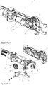
Fig. 1 is a structural schematic drawing of a first electric lopper provided in an embodiment of the present invention. -
Fig. 2 is a structural schematic drawing of a second electric lopper provided in an embodiment of the present invention. -
Fig. 3 is a partial structural schematic drawing of the first electric lopper provided in an embodiment of the present invention. -
Fig. 4 is a first partial exploded drawing of the first electric lopper provided in an embodiment of the present invention. -
Fig. 5 is a second partial exploded drawing of the first electric lopper provided in an embodiment of the present invention. -
Fig. 6 is a third partial exploded drawing of the first electric lopper provided in an embodiment of the present invention. -
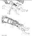
Fig. 7 is a first partial exploded drawing of the second electric lopper provided in an embodiment of the present invention. -
Fig. 8 is a first partial structural schematic drawing of the second electric lopper provided in an embodiment of the present invention. -
Fig. 9 is a structural schematic drawing of a first forked connecting member provided in an embodiment of the present invention. -
Fig. 10 is a structural schematic drawing of a second forked connecting member provided in an embodiment of the present invention. -
Fig. 11 is a second partial structural schematic drawing of the second electric lopper provided in an embodiment of the present invention. -
Fig. 12 is a partial structural schematic drawing of a connecting pole provided in an embodiment of the present invention. -
Fig. 13 is a fourth partial exploded drawing of the first electric lopper provided in an embodiment of the present invention. - The present invention is expounded below in accordance with the embodiments shown in the drawings. The embodiments disclosed on this occasion may be regarded as being non-limiting examples in all respects. The scope of the present invention is not limited by the explanation of the embodiments below, being indicated by the scope of the claims alone, and includes all variants that fall within the scope of the claims and have the same meaning as the scope of the claims.
- The electric lopper provided in the present invention is expounded below in conjunction with particular embodiments.
- As shown in
figs. 1 - 3 , the embodiments of the present invention provide an electric lopper, the electric lopper comprising a handle 1, a connectingpole 2 and apruning component 3 which are connected in sequence. Specifically, thepruning component 3 comprises acasing 31, acontrol mechanism 32 and, connected in sequence, amotive power mechanism 33, a drive mechanism and a cutter set, wherein themotive power mechanism 33 and drive mechanism are disposed in thecasing 31, the cutter set is disposed at that end of thecasing 31 which is remote from themotive power mechanism 33, a switch 4 connected to themotive power mechanism 33 is provided on the handle 1, and the control mechanism is connected to the drive mechanism; the drive mechanism is a worm gear/worm drive mechanism 34 or a ballscrew drive mechanism 35. - In the process of using the electric lopper to prune bushes or branches, etc., the switch 4 on the handle 1 is pressed, the
motive power mechanism 33 is activated by means of the switch 4, and themotive power mechanism 33 transmits motive power to the worm gear/worm drive mechanism 34 or ballscrew drive mechanism 35 connected thereto, thus activating the electric lopper, while travel control is achieved by means of thecontrol mechanism 32 connected to the drive mechanism. - In the electric lopper provided in this embodiment, the drive mechanism is the worm gear/
worm drive mechanism 34 or ballscrew drive mechanism 35; by using the worm gear/worm drive mechanism 34 or ballscrew drive mechanism 35 to replace an existing bevel gear drive mechanism, it is possible not only to reduce noise during transmission but also to effectively increase the smoothness of transmission, thus greatly improving the performance of the electric lopper. - By way of demonstration, as shown in
fig. 4 , the cutter set of the electric lopper may comprise at least one cutter made of at least two different materials. - Specifically, the at least one cutter may comprise a connecting part made of a first material and a cutting part made of a second material, and furthermore, the first material is of lower hardness than the second material, i.e. a second material of greater hardness is used to make the cutting part; thus, in the process of using the cutter to perform cutting, damage to the cutter due to stress concentration can be prevented while ensuring the cutting performance of the cutter, and also, separate replacement is possible when the cutting part or connecting part breaks, facilitating maintenance and reducing maintenance costs. In addition, since the first material used to make the connecting part is of lower hardness, the wear experienced by a drive structure driving the connecting part to move can be effectively reduced, increasing the lifespan of the drive structure and thus increasing the service life of the electric lopper.
- By way of demonstration, as shown in
fig. 4 , in an embodiment of the present invention, the electric lopper employs a worm gear/worm drive; specifically, aworm 341 in the worm gear/worm drive mechanism 34 is connected to themotive power mechanism 33, and asmall gear 343 is provided on aworm gear 342 in theworm drive mechanism 34, the small gear transmitting motive power concentrically with theworm gear 342; thesmall gear 343 is meshed with anupper cutter 36 in the cutter set, and alower cutter 37 in the cutter set is connected to theupper cutter 36 and fixed to thecasing 31. - Specifically, when the electric lopper employs the worm gear/
worm drive mechanism 34, motive power outputted by themotive power mechanism 33 drives theworm 341 to rotate, and thesmall gear 343 on theworm gear 342 meshed with theworm 341 rotates with theworm gear 342, driving theupper cutter 36 meshed with the small gear to reciprocate up and down, cooperating with thelower cutter 37 to prune bushes, etc. - By way of demonstration, the
upper cutter 36 comprises atoothed tail part 361 and an upper cutting head 362 which are connected to each other, wherein thetoothed tail part 361 is meshed with thesmall gear 343. - Specifically, motive power outputted by the
motive power mechanism 33 drives theworm 341 to rotate, and thesmall gear 343 on theworm gear 342 meshed with theworm 341 rotates with theworm gear 342, and by means of thetoothed tail part 361 meshed with the small gear, drives the upper cutting head 362 connected to the toothed tail part to reciprocate up and down, cooperating with thelower cutter 37 to prune bushes, etc. - Specifically, the
toothed tail part 361 is of lower hardness than the upper cutting head 362. - The
small gear 343 is generally of lower hardness than theupper cutter 36 used for cutting, and consequently, in the process of using the electric lopper, thesmall gear 343 experiences severe wear, with the result that the lifespan of the electric lopper is short. In this embodiment, theupper cutter 36 is divided into two parts: the upper cutting head 362 for pruning bushes and branches, etc., is of greater hardness, while thetoothed tail part 361 used for transmission is of lower hardness, making it possible to effectively reduce wear to thesmall gear 343 due to friction of meshing with the tail part of theupper cutter 36, increasing the lifespan of thesmall gear 343, and thus increasing the service life of the electric lopper; in addition, by dividing theupper cutter 36 into two parts, it is possible to prevent cutter damage due to stress concentration, and also, separate replacement is possible when thetoothed tail part 361 or upper cutting head 362 breaks, facilitating maintenance and reducing maintenance costs. - By way of demonstration, as shown in
fig. 4 , thetoothed tail part 361, upper cutting head 362 andlower cutter 37 are connected together by means of a threaded connecting member 38. Specifically, as shown infig. 5 , the threaded connecting member 38 is a stepped connecting member, comprising a cylindrical threaded end 381, a cylindrical middle segment 382, a square prism 383 and a cuboid end 384 which are connected in sequence. The cylindrical threaded end 381 is arranged coaxially with the cylindrical middle segment 382, and the cylindrical threaded end 381 has a smaller diameter than the cylindrical middle segment 382; the circle centre of a cross section of the cylindrical middle segment 382, the centre point of a square cross section of the square prism 383 and the centre point of the cuboid end 384 are all coincident; moreover, the area of the cross section of the cylindrical middle segment 382 is less than the area of the square cross section of the square prism 383, and the area of the square cross section of the square prism 383 is less than the area of that side of the cuboid end 384 which is connected to the square prism 383. - The
toothed tail part 361 and upper cutting head 362 are provided with round through-holes fitting the cylindrical middle segment 382, thelower cutter 37 andcasing 31 are provided with square through-holes fitting the square prism 383, and thecasing 31 is provided with a rectangular recess fitting the cuboid end 384, the square through-hole in thecasing 31 being disposed in the rectangular recess. - Starting at the cuboid end 384, the stepped connecting member passes through the
casing 31,lower cutter 37, upper cutting head 362 andtoothed tail part 361 in sequence; the cylindrical threaded end 381 passes through thetoothed tail part 361 and is connected to a nut. - Optionally, as shown in
fig. 6 , thecontrol mechanism 32 comprises a fixedpin 321 disposed on theworm gear 342 and, mounted on thecasing 31, adirection change switch 322 and a stop switch 323. Specifically, the fixedpin 321 touches thedirection change switch 322 as theworm gear 342 rotates, theworm gear 342 rotates in the opposite direction, theworm gear 342 touches the stop switch 323 while rotating in the opposite direction, and theworm gear 342 stops rotating. - By way of demonstration, as shown in
figs. 2 and7 , in another embodiment of the present invention, the electric lopper employs a ball screw drive; specifically, the ballscrew drive mechanism 35 comprises ascrew 351 and a screw nut 352 mounted on thescrew 351, thescrew 351 being connected to themotive power mechanism 33, the screw nut 352 being connected to anupper cutter 36 in the cutter set, and alower cutter 37 in the cutter set being connected to theupper cutter 36 and fixed to thecasing 31. - Specifically, when the electric lopper employs the ball
screw drive mechanism 35, motive power outputted by themotive power mechanism 33 is converted from rotational motion to linear motion via thescrew 351 and screw nut 352, driving the screw nut 352 to reciprocate, and thus driving theupper cutter 36 connected to the screw nut 352 to reciprocate, cooperating with thelower cutter 37 to prune bushes, etc. - By way of demonstration, as shown in
figs. 7 - 10 , the screw nut 352 is connected to theupper cutter 36 by means of a forked connectingmember 39. The forked connectingmember 39 provided in embodiments of the present invention is always one component, with strong integrity, and good structural strength, and being simple to fit, and can be made by stamping a sheet, at a low cost. - Further optionally, as shown in
fig. 10 , the forked connectingmember 39 is an integrally stamped forked connecting member, which does not require any welding and has better structural strength and load-bearing ability; where installation space allows, the forked connectingmember 39 shown infig. 10 may preferably be used. - In addition, as shown in
fig. 8 , the forked connectingmember 39 is connected to the screw nut 352 by means of countersunk screws 5; thus, the forked connectingmember 39 can be effectively prevented from opening outwards when subjected to a force, and furthermore, when theupper cutter 36 completes one action of cutting and return, the countersunk screws 5 can bear the pulling force of the forked connectingmember 39, increasing the stability of the electric lopper structure. - It should be added that, as shown in
fig. 8 , two ends of the forked connectingmember 39 that are connected to the screw nut 352 are arc-shaped ends; thus, an arc fit can be realized between the forked connectingmember 39 and the screw nut 352, and when the electric lopper is cutting, the screw nut 352 can bear a greater pushing force, preventing the countersunk screws 5 from being pushed to destruction; moreover, relative rotation of the forked connectingmember 39 around the centre of the arc is also possible, so the forked connectingmember 39 will not be locked up. - By way of demonstration, a sealing ring may also be provided between the forked connecting
member 39 and thecasing 31, to prevent the ingress of impurities and dust, etc., into thecasing 31 from the surroundings, and consequent damage to the electric lopper. - In addition, as shown in
fig. 11 , at the position where thelower cutter 37 is connected to thecasing 31, thecasing 31 is further provided with ahooked structure 311 facing away from thelower cutter 37; thus, the hooked structure can be used to hook off branches, etc., that have been cut, avoiding a situation where branches that have been cut become hung on other branches. - Optionally, in this embodiment, the
control mechanism 32 may comprise a Hall sensor connected to the screw nut 352; movement of the screw nut 352 is controlled by means of the Hall sensor, thereby controlling the travel of the electric lopper. - The specific method and process of using the Hall sensor to control movement of the screw nut as described above are the same as the process and method of using a Hall sensor to control travel in the prior art; those skilled in the art may refer to the existing process and method of using a Hall sensor to control travel, and this is not described further in the embodiments of the present invention.
- In addition, as shown in
figs. 1, 2 and3 , in the two embodiments provided in the present invention that are described above, a visibility enhancing feature is provided for the cutter set, thus enabling a user to clearly distinguish the relative positions of the cutters and the plant to be pruned during use. In some embodiments, the visibility enhancing feature comprises various features that make the cutters easier for the user to see, such as luminous features, highly reflective features, fluorescent features, brightly coloured features and pattern features. The visibility enhancing feature may be provided to the cutter set in various ways. By way of demonstration, as shown in the figures, in some embodiments, an additional material coating may be applied to the cutter set. Preferably, the material coating is provided on an outside surface of at least one cutter in the cutter set. Further preferably, the material coating is provided on an outside surface of thelower cutter 37 in the cutter set. In some embodiments, an additional visibility enhancing component may be provided for the cutter set, the visibility enhancing component being attached to one of the cutters in the cutter set. The visibility enhancing component has the abovementioned visibility enhancing feature. - Furthermore, in the two embodiments provided in the present invention that are described above, the
motive power mechanism 33 may in each case comprise a DC motor 331 and a planetarygear speed reducer 332, with an input end of the planetarygear speed reducer 332 being connected to an output end of the DC motor 331, and an output end of the planetarygear speed reducer 332 being connected to the drive mechanism. Specifically, the output end of the planetarygear speed reducer 332 is connected to theworm 341, or the output end of the planetarygear speed reducer 332 is connected to thescrew 351, and motive power outputted by the DC motor 331 is transmitted to the worm gear/worm drive mechanism 34 or ballscrew drive mechanism 35 after speed reduction by the planetarygear speed reducer 332. - Optionally, a power supply means supplying power to the DC motor 331 is provided in the handle 1. The DC motor 331 may be a brushless DC motor or a lower-cost brushed DC motor; the embodiments of the present invention do not impose any restriction in this respect.
- Optionally, as shown in
fig. 12 , the connectingpole 2 may be a telescopic connecting pole. - By way of demonstration, in one embodiment, as shown in
fig. 12 , the connectingpole 2 may comprise an inner tube 21, an outer tube 22, and a locking means 23 fitted round the outer tube 22. The locking means 23 comprises abase 231, a first locking sleeve 232 fitted round the outer tube 22 in a fixed manner, a second locking sleeve 233 fitted round the inner tube 21 in a slideable manner, and a lockinglever 234 mounted on the first locking sleeve 232 and second locking sleeve 233. By way of demonstration, when the user turns the lockinglever 234 to a released position from a locked position in which it is tightly against the first locking sleeve 232 and second locking sleeve 233, the pressure applied to the outer tube 22 by the first locking sleeve 232 is reduced, and the inner tube 21 can slide freely; the user can pull out or push in the inner tube 21 by a certain distance as required, and then turn the lockinglever 234 from the released position to the locked position, to realize length adjustment of the connectingpole 2. - By way of demonstration, in another embodiment, the connecting
pole 2 may comprise an inner tube, an outer tube, and a sleeve connected to the inner tube and outer tube; an inner surface of the sleeve that is connected to the outer tube, and an end outer surface of the outer tube that is connected to the sleeve, are provided with threads which mate with each other. After releasing the sleeve by turning, the user can freely slide the inner tube in the outer tube, pull out or push in the inner tube by a certain distance as required, and then tighten the sleeve by turning, to realize length adjustment of the connectingpole 2. - Of course, those skilled in the art may also carry out design with reference to telescopic poles in the prior art; the embodiments of the present invention do not impose any restriction in this respect.
- Optionally, as shown in
fig. 13 , thepruning component 3 is connected to the connectingpole 2 rotatably. - Further optionally, as shown in
fig. 13 , thepruning component 3 is connected to the connectingpole 2 rotatably by means of a rotary button 6. Specifically, the rotary button is a T-shaped button, a boss 62 is provided along a side face of an upper end 61 of the T-shaped button, and multiple protrusions 63 are provided uniformly on the boss 62; an inside face, connected to the upper end 61 of the T-shaped button, of the connectingpole 2 is provided with multiple slots fitting the protrusions 63; and a mounting platform 312, provided with a slot fitting alower end 64 of the T-shaped button, is provided in thecasing 31. - By way of demonstration, when it is necessary to turn the
pruning component 3, the user presses the rotary button 6, and the protrusions 63 of the upper end 61 of the rotary button 6 will then disengage from the slots of the inside face, connected to the upper end 61 of the T-shaped button, of the connectingpole 2; at the same time, thelower end 64 remains mated with the mounting platform 312, and the rotary button 6 is fixed relative to thepruning component 3 but moveable relative to the connectingpole 2, so thepruning component 3 can be turned. - In addition, as shown in
fig. 13 , the T-shaped button further comprises a spring 65, which passes through thelower end 64 and is mounted between an inside face of the upper end 61 and the mounting platform 312. When thepruning component 3 is turned to the desired angle, the T-shaped button can be released; the spring 65 will automatically push up the T-shaped button, and the protrusions 63 will engage in the slots in the inside face, connected to the upper end 61 of the T-shaped button, of the connectingpole 2, locking the current angle of thepruning component 3. - Those skilled in the art, after considering this description and implementing the invention disclosed herein, will readily think of other embodiments of the present invention. The present application is intended to cover any variants, uses or adaptive modifications of the present invention; these variants, uses or adaptive modifications comply with the general principles of the present invention and include undisclosed common knowledge or customary technical methods in the art. The description and embodiments are regarded as being demonstrative only; the true scope and spirit of the present invention are indicated by the claims.
- It should be understood that the present invention is not limited to the embodiment methods and structures already described above and the precise structures shown in the drawings, and can be amended and changed in various ways without departing from the scope thereof. The scope of the present invention is limited only by the attached claims.
| 1- | handle; | 2- | connecting pole; | 21- | inner tube; |
| 22- | outer tube; | 23- | locking means; | 3- | pruning component; |
| 31- | casing; | 311- | hooked structure; | 312- | mounting platform; |
| 32- | control mechanism; | 321- | fixed pin; | 322- | direction change switch; |
| 323- | stop switch; | 33- | motive power mechanism; | 331- | DC motor; |
| 332- | planetary gear speed reducer; | 4- | switch; | 34- | worm gear/worm drive mechanism; |
| 341- | worm; | 342- | worm gear; | 343- | small gear; |
| 35- | ball screw drive mechanism; | 351- | screw; | 352- | screw nut; |
| 36- | upper cutter; | 361-toothed tail part; | 362- | upper cutting head; | |
| 37- | lower cutter; | 38- | threaded connecting member; | 381- | cylindrical threaded end; |
| 382- | cylindrical middle segment; | 383- | square prism; | 384- | cuboid end; |
| 39- | forked connecting member; | 5- | countersunk screw; | 6- | rotary button; |
| 61- | upper end; | 62- | boss; | 63- | protrusion; |
| 64- | lower end; | 65- | spring. |
Claims (15)
- Electric lopper, characterized by comprising a handle (1), a connecting pole (2) and a pruning component (3) which are connected in sequence, wherein the pruning component (3) comprises a casing (31), a control mechanism (32) and, connected in sequence, a motive power mechanism (33), a drive mechanism and a cutter set, wherein the motive power mechanism (33) and the drive mechanism are disposed in the casing (31), the cutter set is disposed at that end of the casing (31) which is remote from the motive power mechanism (33), a switch (4) connected to the motive power mechanism (33) is provided on the handle (1), and the control mechanism (32) is connected to the drive mechanism;
the drive mechanism is a worm gear/worm drive mechanism (34) or a ball screw drive mechanism (35). - Electric lopper according to Claim 1, characterized in that a worm (341) in the worm gear/worm drive mechanism (34) is connected to the motive power mechanism (33), and a small gear (343) is provided on a worm gear (342) in the worm drive mechanism (34), the small gear transmitting motive power concentrically with the worm gear (342); the small gear (343) is meshed with an upper cutter (36) in the cutter set, and a lower cutter (37) in the cutter set is connected to the upper cutter (36) and fixed to the casing (31).
- Electric lopper according to Claim 2, characterized in that the upper cutter (36) comprises a toothed tail part (361) and an upper cutting head (362) which are connected to each other, wherein the toothed tail part (361) is meshed with the small gear (343), wherein the toothed tail part (361) is preferably of lower hardness than the upper cutting head (362), and wherein preferably the upper cutting head (362) and the lower cutter (37) are connected together by means of a threaded connecting member (38).
- Electric lopper according to Claim 3, characterized in that the threaded connecting member (38) is a stepped connecting member, comprising a cylindrical threaded end (381), a cylindrical middle segment (382), a square prism (383) and a cuboid end (384) which are connected in sequence, wherein the cylindrical threaded end (381) is arranged coaxially with the cylindrical middle segment (382), and the cylindrical threaded end (381) has a smaller diameter than the cylindrical middle segment (382); the circle centre of a cross section of the cylindrical middle segment (382), the centre point of a square cross section of the square prism (383) and the centre point of the cuboid end (384) are all coincident; moreover, the area of the cross section of the cylindrical middle segment (382) is less than the area of the square cross section of the square prism (383), and the area of the square cross section of the square prism (383) is less than the area of that side of the cuboid end (384) which is connected to the square prism (383);
the toothed tail part (361) and the upper cutting head (362) are provided with round through-holes fitting the cylindrical middle segment (382), the lower cutter (37) and the casing (31) are provided with square through-holes fitting the square prism (383), and the casing (31) is provided with a rectangular recess fitting the cuboid end (384), the square through-hole in the casing (31) being disposed in the rectangular recess;
starting at the cuboid end (384), the stepped connecting member passes through the casing (31), the lower cutter (37), the upper cutting head (362) and the toothed tail part (361) in sequence; the cylindrical threaded end (381) passes through the toothed tail part (361) and is connected to a nut. - Electric lopper according to Claim 2, characterized in that the control mechanism (32) comprises a fixed pin (321) disposed on the worm gear (342) and, mounted on the casing, a direction change switch (322) and a stop switch (323); the fixed pin (321) touches the direction change switch (322) as the worm gear (342) rotates, the worm gear (342) rotates in the opposite direction, the worm gear (342) touches the stop switch (323) while rotating in the opposite direction, and the worm gear (342) stops rotating.
- Electric lopper according to Claim 1, characterized in that the ball screw drive mechanism (35) comprises a screw (351) and a screw nut (352) mounted on the screw (351), the screw (351) being connected to the motive power mechanism (33), the screw nut (352) being connected to an upper cutter (36) in the cutter set, and a lower cutter (37) in the cutter set being connected to the upper cutter (36) and fixed to the casing (31).
- Electric lopper according to Claim 6, characterized in that the screw nut (352) is connected to the upper cutter (36) by means of a forked connecting member (39), wherein the forked connecting member (39) is preferably an integrally stamped forked connecting member, wherein the forked connecting member (39) is preferably connected to the screw nut (352) by means of a countersunk screw (5), and wherein preferably two ends of the forked connecting member (39) that are connected to the screw nut (352) are arc-shaped ends.
- Electric lopper according to Claim 7, characterized in that a sealing ring is provided between the forked connecting member (39) and the casing (31).
- Electric lopper according to Claim 6, characterized in that the control mechanism (32) comprises a Hall sensor connected to the screw nut (352), movement of the screw nut (352) being controlled by means of the Hall sensor.
- Electric lopper according to Claim 1, characterized in that the motive power mechanism (33) comprises a DC motor (331) and a planetary gear speed reducer (332), with an input end of the planetary gear speed reducer (332) being connected to an output end of the DC motor (331), and an output end of the planetary gear speed reducer (332) being connected to the drive mechanism, wherein preferably a power supply means supplying power to the DC motor (331) is provided in the handle (1)
- Electric lopper according to Claim 1, characterized in that the connecting pole (2) is a telescopic connecting pole.
- Electric lopper according to Claim 1, characterized in that the pruning component (3) is connected to the connecting pole (2) rotatably.
- Electric lopper according to Claim 12, characterized in that the pruning component (3) is connected to the connecting pole (2) rotatably by means of a rotary button (6); the rotary button (6) is a T-shaped button, a boss (62) is provided along a side face of an upper end (61) of the T-shaped button, and multiple protrusions (63) are provided uniformly on the boss (62); an inside face, connected to the upper end (61), of the connecting pole (2) is provided with multiple slots fitting the protrusions (63); and a mounting platform (312), provided with a slot fitting a lower end (64) of the T-shaped button, is provided in the casing (31), wherein the T-shaped button preferably further comprises a spring (65), which passes through the lower end (64) and is mounted between an inside face of the upper end (61) and the mounting platform (312).
- Electric lopper according to Claim 1, characterized in that the cutter set comprises at least one cutter made of at least two different materials, wherein preferably the at least one cutter comprises a connecting part made of a first material and a cutting part made of a second material, wherein the first material is preferably of lower hardness than the second material.
- Electric lopper according to Claim 1, characterized in that the cutter set comprises a visibility enhancing feature, wherein the visibility enhancing feature is preferably selected from at least one of luminous features, highly reflective features, fluorescent features, brightly coloured features and pattern features, and wherein the visibility enhancing feature is preferably provided on an outside surface of at least one cutter in the cutter set.
Applications Claiming Priority (1)
| Application Number | Priority Date | Filing Date | Title |
|---|---|---|---|
| CN201910837921.6A CN112438132B (en) | 2019-09-05 | 2019-09-05 | Electric pruning shears |
Publications (2)
| Publication Number | Publication Date |
|---|---|
| EP3788866A2 true EP3788866A2 (en) | 2021-03-10 |
| EP3788866A3 EP3788866A3 (en) | 2021-05-05 |
Family
ID=72340212
Family Applications (1)
| Application Number | Title | Priority Date | Filing Date |
|---|---|---|---|
| EP20193986.5A Pending EP3788866A3 (en) | 2019-09-05 | 2020-09-02 | Electric lopper |
Country Status (6)
| Country | Link |
|---|---|
| US (1) | US11533856B2 (en) |
| EP (1) | EP3788866A3 (en) |
| CN (1) | CN112438132B (en) |
| AU (1) | AU2020102112A4 (en) |
| CA (1) | CA3092714C (en) |
| MX (1) | MX2020009113A (en) |
Families Citing this family (17)
| Publication number | Priority date | Publication date | Assignee | Title |
|---|---|---|---|---|
| JP6830558B1 (en) * | 2020-04-21 | 2021-02-17 | アルスコーポレーション株式会社 | Electric pruning shears |
| USD1000243S1 (en) * | 2021-07-09 | 2023-10-03 | Suzhou Ailixi Brushless Motor Co., Ltd. | Electric scissors |
| CN114227792B (en) * | 2021-12-08 | 2024-12-27 | 东莞市嘉航实业有限公司 | A protective mechanism and shearing device using the same |
| AU2023202439A1 (en) * | 2022-04-25 | 2023-11-09 | Techtronic Cordless Gp | Power lopper attachment |
| CN117445100A (en) * | 2022-07-19 | 2024-01-26 | 南京泉峰科技有限公司 | a pole saw |
| US20240066729A1 (en) * | 2022-08-26 | 2024-02-29 | Techtronic Cordless Gp | Tool with selectively engagable tool head |
| CN115280988B (en) * | 2022-09-07 | 2023-04-14 | 临沂博力通化油器有限公司 | Telescopic branch trimming device capable of achieving accurate auxiliary positioning |
| CN115443822B (en) * | 2022-09-30 | 2024-07-16 | 中山庆琏金属制品有限公司 | Steerable overhead shears |
| US12508720B2 (en) * | 2022-10-07 | 2025-12-30 | Kubota Corporation | End effector including cutting blade and pulley assembly |
| CN116114488B (en) * | 2023-01-06 | 2024-03-08 | 宁波创跃园林工具有限公司 | Pruning machine |
| US12342768B2 (en) * | 2023-02-09 | 2025-07-01 | Fiskars Finland Oy Ab | Tree pruner |
| USD1005805S1 (en) * | 2023-07-06 | 2023-11-28 | Jinyun Mailin Tools Co., Ltd | Garden tool |
| USD1005068S1 (en) * | 2023-07-14 | 2023-11-21 | Jinhua Xiaoyi Tools Co., Ltd | High branch pole |
| CN117256339B (en) * | 2023-11-14 | 2024-11-26 | 东莞市嘉航实业有限公司 | A medium and long distance shearing device and control method |
| USD1104671S1 (en) * | 2023-12-19 | 2025-12-09 | Zhejiang Prulde Electric Appliance Co., Ltd. | Garden tool |
| DE102024106744A1 (en) * | 2024-03-08 | 2025-09-11 | Einhell Germany Ag | Wood separator |
| USD1105867S1 (en) * | 2024-07-18 | 2025-12-16 | Longchang Chen | Electric branch pruner |
Family Cites Families (29)
| Publication number | Priority date | Publication date | Assignee | Title |
|---|---|---|---|---|
| FR2585612A1 (en) * | 1985-08-02 | 1987-02-06 | Germain Pierre | ELECTRICAL SECTOR |
| FR2614568B1 (en) | 1987-04-28 | 1989-07-28 | Pellenc & Motte | PORTABLE POWER TOOL WITH POSITION CONTROL |
| US6748663B2 (en) * | 2002-08-15 | 2004-06-15 | Fiskars Consumer Oy Ab | Lopper |
| JP2007195469A (en) | 2006-01-27 | 2007-08-09 | Minami Nasu Seiko Kk | Scissors for cutting branch at high position |
| US20080173138A1 (en) * | 2006-08-15 | 2008-07-24 | Dayton Douglas C | Systems and methods of a vacuum cup bulb changer power tool system with interchangeable functional attachments |
| JP2008048669A (en) | 2006-08-24 | 2008-03-06 | Max Co Ltd | Electric pruning scissors |
| FR2935175B1 (en) | 2008-08-22 | 2011-02-11 | Pellenc Sa | DEVICE FOR DETERMINING THE RELATIVE POSITION BETWEEN TWO OR MORE OF WHICH IS AT LEAST MOVABLE, AND MACHINES AND APPARATUSES BY APPLYING |
| CN201563409U (en) * | 2009-09-15 | 2010-09-01 | 南京德朔实业有限公司 | Electric scissors |
| TWM376132U (en) * | 2009-11-06 | 2010-03-21 | Natura Innovation Ltd | High lopper |
| EP2345749B1 (en) * | 2010-01-14 | 2015-12-02 | Siemens Aktiengesellschaft | Gear assembly and wind turbine |
| FR2955734B1 (en) * | 2010-02-03 | 2012-03-09 | Infaco | SECTOR FOR THE SIZE OF PLANTS |
| FR2957834B1 (en) | 2010-03-24 | 2012-03-09 | Infaco | DEVICE FOR POSITIONALLY CONTROLLING TWO ELEMENTS RELATIVE TO EACH OTHER, SUCH AS BLADES OF CUTTER GENERATOR TOOLS AND CUTTING TOOL COMPRISING SAME |
| US20110258859A1 (en) * | 2010-04-22 | 2011-10-27 | Robert Theodore Schofield | Cutting device and method |
| US8522444B2 (en) * | 2011-01-04 | 2013-09-03 | Jiin Haur Industrial Co., Ltd. | Cable control set for extended reach garden shears |
| CN102884949B (en) * | 2011-07-22 | 2014-07-30 | 南京德朔实业有限公司 | Electric pruning shears |
| CN102907268B (en) | 2011-08-05 | 2016-01-20 | 方培锵 | Electric garden shears |
| KR101157783B1 (en) * | 2012-01-02 | 2012-06-25 | 양승철 | Safety scissors |
| ES2828089T3 (en) * | 2012-05-04 | 2021-05-25 | Felco Sa | Power tool and assembly procedure for said power tool |
| EP2844057B1 (en) * | 2012-05-04 | 2016-04-27 | FELCO Motion SA | Handheld power tool |
| EP2853148B1 (en) | 2013-09-26 | 2017-11-15 | Ningbo Zhenhai Greatwall Automobile Parts Factory | Electrical tree cutting device |
| CN203537937U (en) * | 2013-09-26 | 2014-04-16 | 宁波市镇海长城汽车摩托车部件厂 | Novel electrical fruit tree pruning shears |
| CN203537939U (en) * | 2013-11-18 | 2014-04-16 | 李玉敏 | Electric pruning shears used for pruning upper branches |
| KR101480826B1 (en) | 2014-09-29 | 2015-01-09 | 김재중 | Electric pruning shears |
| CN205755767U (en) * | 2016-05-27 | 2016-12-07 | 新疆农业科学院园艺作物研究所 | A kind of flexible pruning device being applicable to walnut |
| CN205865245U (en) * | 2016-06-28 | 2017-01-11 | 东莞市嘉航实业有限公司 | Swing Tooth Large Opening Scissors |
| CN206808156U (en) * | 2017-05-25 | 2017-12-29 | 东莞市嘉航实业有限公司 | electric scissors |
| US20190357444A1 (en) * | 2018-05-28 | 2019-11-28 | Shang Gu Enterprise Co., Ltd. | Garden Scissors |
| CN209047078U (en) * | 2018-07-09 | 2019-07-02 | 张作文 | Shrub and hedge trimmer |
| CN210610388U (en) * | 2019-09-05 | 2020-05-26 | 创科无线普通合伙 | Electric pruning shears |
-
2019
- 2019-09-05 CN CN201910837921.6A patent/CN112438132B/en active Active
-
2020
- 2020-09-01 US US17/009,357 patent/US11533856B2/en active Active
- 2020-09-02 EP EP20193986.5A patent/EP3788866A3/en active Pending
- 2020-09-02 AU AU2020102112A patent/AU2020102112A4/en active Active
- 2020-09-02 MX MX2020009113A patent/MX2020009113A/en unknown
- 2020-09-03 CA CA3092714A patent/CA3092714C/en active Active
Also Published As
| Publication number | Publication date |
|---|---|
| US20210068349A1 (en) | 2021-03-11 |
| CN112438132B (en) | 2025-09-12 |
| CA3092714A1 (en) | 2021-03-05 |
| CA3092714C (en) | 2023-01-10 |
| MX2020009113A (en) | 2021-03-08 |
| US11533856B2 (en) | 2022-12-27 |
| AU2020102112A4 (en) | 2020-10-08 |
| EP3788866A3 (en) | 2021-05-05 |
| CN112438132A (en) | 2021-03-05 |
Similar Documents
| Publication | Publication Date | Title |
|---|---|---|
| CA3092714C (en) | Electric pole lopper | |
| US8047100B2 (en) | Tool assembly having telescoping fastener support | |
| CA2823758C (en) | Chain saw | |
| EP2213426B1 (en) | Electric Scissors | |
| US20220078978A1 (en) | Hedge Trimmer | |
| CN210610388U (en) | Electric pruning shears | |
| EP3228421A1 (en) | Electric rivet nut gun | |
| US8826546B2 (en) | Cutting assembly for hand-held power tool | |
| WO2021232642A1 (en) | Dual blade transmission mechanism and electric shears having said dual blade transmission mechanism | |
| CN206808156U (en) | electric scissors | |
| ATE410656T1 (en) | DEVICE FOR ELECTRICALLY CONTROLLING A MACHINE WEAPON | |
| CN103851585A (en) | Adjusting structure of lamp irradiating directions and angles | |
| US4284109A (en) | Electric conductor wrapping tool | |
| US9333637B2 (en) | Multi-tool for fasteners | |
| CN102577844B (en) | Electric pruning device | |
| CN216111972U (en) | Speed reducer with controllable output quantity | |
| CN220769208U (en) | Manual-automatic integrated window opener | |
| CN104455639A (en) | Valve control mechanism | |
| CN224250256U (en) | Chassis system and mowing equipment | |
| AU2013100077A4 (en) | A Multi-Tool For Fasteners | |
| JP2006250303A (en) | Manually operated valve | |
| CN102013345B (en) | Automatic switching-on controller with displaceable control handles | |
| CN121097546A (en) | Portable electric cable tie tool | |
| CN120513777A (en) | Power-assisted shears | |
| KR20260027294A (en) | Electric shears |
Legal Events
| Date | Code | Title | Description |
|---|---|---|---|
| PUAI | Public reference made under article 153(3) epc to a published international application that has entered the european phase |
Free format text: ORIGINAL CODE: 0009012 |
|
| STAA | Information on the status of an ep patent application or granted ep patent |
Free format text: STATUS: THE APPLICATION HAS BEEN PUBLISHED |
|
| AK | Designated contracting states |
Kind code of ref document: A2 Designated state(s): AL AT BE BG CH CY CZ DE DK EE ES FI FR GB GR HR HU IE IS IT LI LT LU LV MC MK MT NL NO PL PT RO RS SE SI SK SM TR |
|
| AX | Request for extension of the european patent |
Extension state: BA ME |
|
| PUAL | Search report despatched |
Free format text: ORIGINAL CODE: 0009013 |
|
| AK | Designated contracting states |
Kind code of ref document: A3 Designated state(s): AL AT BE BG CH CY CZ DE DK EE ES FI FR GB GR HR HU IE IS IT LI LT LU LV MC MK MT NL NO PL PT RO RS SE SI SK SM TR |
|
| RIC1 | Information provided on ipc code assigned before grant |
Ipc: A01G 3/033 20060101AFI20210330BHEP Ipc: A01G 3/037 20060101ALI20210330BHEP Ipc: A01G 3/025 20060101ALI20210330BHEP |
|
| STAA | Information on the status of an ep patent application or granted ep patent |
Free format text: STATUS: REQUEST FOR EXAMINATION WAS MADE |
|
| 17P | Request for examination filed |
Effective date: 20211104 |
|
| RBV | Designated contracting states (corrected) |
Designated state(s): AL AT BE BG CH CY CZ DE DK EE ES FI FR GB GR HR HU IE IS IT LI LT LU LV MC MK MT NL NO PL PT RO RS SE SI SK SM TR |
|
| STAA | Information on the status of an ep patent application or granted ep patent |
Free format text: STATUS: EXAMINATION IS IN PROGRESS |
|
| 17Q | First examination report despatched |
Effective date: 20241213 |