EP3788857A1 - Housing and electric mower - Google Patents
Housing and electric mower Download PDFInfo
- Publication number
- EP3788857A1 EP3788857A1 EP20179008.6A EP20179008A EP3788857A1 EP 3788857 A1 EP3788857 A1 EP 3788857A1 EP 20179008 A EP20179008 A EP 20179008A EP 3788857 A1 EP3788857 A1 EP 3788857A1
- Authority
- EP
- European Patent Office
- Prior art keywords
- housing
- holes
- outer circumferential
- gutter member
- inner hole
- Prior art date
- Legal status (The legal status is an assumption and is not a legal conclusion. Google has not performed a legal analysis and makes no representation as to the accuracy of the status listed.)
- Granted
Links
Images



Classifications
-
- A—HUMAN NECESSITIES
- A01—AGRICULTURE; FORESTRY; ANIMAL HUSBANDRY; HUNTING; TRAPPING; FISHING
- A01D—HARVESTING; MOWING
- A01D34/00—Mowers; Mowing apparatus of harvesters
- A01D34/01—Mowers; Mowing apparatus of harvesters characterised by features relating to the type of cutting apparatus
- A01D34/412—Mowers; Mowing apparatus of harvesters characterised by features relating to the type of cutting apparatus having rotating cutters
- A01D34/63—Mowers; Mowing apparatus of harvesters characterised by features relating to the type of cutting apparatus having rotating cutters having cutters rotating about a vertical axis
- A01D34/81—Casings; Housings
-
- A—HUMAN NECESSITIES
- A01—AGRICULTURE; FORESTRY; ANIMAL HUSBANDRY; HUNTING; TRAPPING; FISHING
- A01D—HARVESTING; MOWING
- A01D34/00—Mowers; Mowing apparatus of harvesters
- A01D34/01—Mowers; Mowing apparatus of harvesters characterised by features relating to the type of cutting apparatus
- A01D34/412—Mowers; Mowing apparatus of harvesters characterised by features relating to the type of cutting apparatus having rotating cutters
- A01D34/63—Mowers; Mowing apparatus of harvesters characterised by features relating to the type of cutting apparatus having rotating cutters having cutters rotating about a vertical axis
- A01D34/64—Mowers; Mowing apparatus of harvesters characterised by features relating to the type of cutting apparatus having rotating cutters having cutters rotating about a vertical axis mounted on a vehicle, e.g. a tractor, or drawn by an animal or a vehicle
-
- A—HUMAN NECESSITIES
- A01—AGRICULTURE; FORESTRY; ANIMAL HUSBANDRY; HUNTING; TRAPPING; FISHING
- A01D—HARVESTING; MOWING
- A01D34/00—Mowers; Mowing apparatus of harvesters
- A01D34/01—Mowers; Mowing apparatus of harvesters characterised by features relating to the type of cutting apparatus
- A01D34/412—Mowers; Mowing apparatus of harvesters characterised by features relating to the type of cutting apparatus having rotating cutters
- A01D34/63—Mowers; Mowing apparatus of harvesters characterised by features relating to the type of cutting apparatus having rotating cutters having cutters rotating about a vertical axis
- A01D34/76—Driving mechanisms for the cutters
- A01D34/78—Driving mechanisms for the cutters electric
-
- A—HUMAN NECESSITIES
- A01—AGRICULTURE; FORESTRY; ANIMAL HUSBANDRY; HUNTING; TRAPPING; FISHING
- A01D—HARVESTING; MOWING
- A01D69/00—Driving mechanisms or parts thereof for harvesters or mowers
- A01D69/02—Driving mechanisms or parts thereof for harvesters or mowers electric
-
- H—ELECTRICITY
- H05—ELECTRIC TECHNIQUES NOT OTHERWISE PROVIDED FOR
- H05K—PRINTED CIRCUITS; CASINGS OR CONSTRUCTIONAL DETAILS OF ELECTRIC APPARATUS; MANUFACTURE OF ASSEMBLAGES OF ELECTRICAL COMPONENTS
- H05K5/00—Casings, cabinets or drawers for electric apparatus
- H05K5/02—Details
- H05K5/0213—Venting apertures; Constructional details thereof
- H05K5/0214—Venting apertures; Constructional details thereof with means preventing penetration of rain water or dust
-
- H—ELECTRICITY
- H05—ELECTRIC TECHNIQUES NOT OTHERWISE PROVIDED FOR
- H05K—PRINTED CIRCUITS; CASINGS OR CONSTRUCTIONAL DETAILS OF ELECTRIC APPARATUS; MANUFACTURE OF ASSEMBLAGES OF ELECTRICAL COMPONENTS
- H05K7/00—Constructional details common to different types of electric apparatus
- H05K7/14—Mounting supporting structure in casing or on frame or rack
- H05K7/1422—Printed circuit boards receptacles, e.g. stacked structures, electronic circuit modules or box like frames
- H05K7/1427—Housings
- H05K7/1432—Housings specially adapted for power drive units or power converters
Definitions
- the present invention relates to a housing mounted on a working machine and holding parts, and an electric mower equipped with the housing.
- Working machines such as electric mowers are equipped with a housing holding various parts including electronic components and circuit boards.
- the housing has a space for holding parts therein, and for example has a rectangular parallelepiped shape made of six outer circumferential plates combined.
- ventilation needs to be provided for the housing in consideration of heat dissipation of parts and the like, and openings are formed in the outer circumferential plates.
- Working machine may be exposed to wind and rain, and receive jetted water, for example when it is washed. At such a time, when water enters the housing, parts will get wet, which may result in a failure or malfunction of the working machine. Therefore, the housing is equipped with a mechanism to secure ventilation and to prevent water from entering.
- Patent Literature 1 Japanese Patent Application Publication No. 2000-295721
- the housing needs to secure a space to hold various parts. Therefore, there has been a demand for a mechanism having a simple configuration and a capability to secure ventilation property and waterproof property.
- the housing according to an embodiment of the present invention is a housing for holding parts.
- the housing includes: a plurality of outer circumferential plates connected with each other to form a first enclosed space, one or more of the outer circumferential plates having a total of two or more outer holes formed therein; and a gutter member connected to at least two outer circumferential plates, the gutter member having an inner hole formed therein, wherein the outer circumferential plates and the gutter member form a second enclosed space, the outer holes communicate with the second enclosed space, and the inner hole is provided to be offset from the lines passing through the respective outer holes, the lines being perpendicular to the outer circumferential plate in which the outer holes are formed.
- This configuration secures ventilation property while air is allowed to circulate between the inside and the outside of the housing via the outer holes and the inner hole.
- the outer holes and the inner hole are provided to be offset. Therefore, water which has entered the second enclosed space from the outer holes is easily passed through the enclosed space of the gutter member and discharged from the outer holes to the outside of the housing without entering the inside of the housing from the inner hole. With the above, ventilation property and waterproof property are effectively secured with the simple configuration.
- the outer holes are formed in the outer circumferential plate which serves as a bottom face when the housing is in use.
- the gutter member may be disposed over two adjacent outer circumferential plates.
- the gutter member is simply configured over the two outer circumferential plates, and is disposed at a corner part in the housing. Therefore, the gutter member can be configured with the simple configuration without occupying much space in the housing.
- the outer holes are preferably two holes formed in the outer circumferential plate, and the inner hole is preferably provided near a middle point between the two outer holes when viewed from a plane parallel to the outer circumferential plate in which the outer holes are formed.
- the inner hole may be an elongated hole along a contacting line between the outer circumferential plate and the gutter member.
- a plurality of the gutter members may be provided to form the respective second enclosed spaces, the outer holes may communicate with the respective second enclosed spaces and the inner holes may communicate with the respective second enclosed spaces.
- the number of the gutter members can be adjusted according to a required quantity of airflow, and sufficient ventilation property can be easily secured while waterproof property is secured.
- the electric mower according to an embodiment of the invention is equipped with the housing.
- the electric mower With the housing in which ventilation property and waterproof property are secured, the electric mower can maintain operation accuracy of parts such as electronic components mounted in the housing, and excellent mowing operation can be maintained.
- the term “front” means forward with respect to the front-rear direction of a vehicle body (traveling direction), and “rear” means rearward with respect to the front-rear direction of the vehicle body (traveling direction) herein.
- the left-right direction or the lateral direction means the transverse direction of the vehicle body (vehicle body width direction) orthogonal to the front-rear direction of the vehicle body.
- “Upper” or “lower” is a positional relation with the vertical direction (perpendicular direction) of the vehicle body and means a relation to height above ground level.
- an electric mower is shown as an example of work vehicle.
- the electric mower includes a vehicle body 1, a pair of right and left front wheels 11, 11, a pair of right and left rear wheels 12, 12, a mower unit 2, and a battery storage unit 3.
- the pair of right and left front wheels 11, 11 are disposed in a front part of the vehicle body 1, and the pair of right and left rear wheels 12, 12 are disposed in a rear part of the vehicle body 1.
- the mower unit 2 is supported between the pair of right and left front wheels 11, 11 and the pair of right and left rear wheels 12, 12, in a front-rear direction and a left-right direction in a lower part of the vehicle body 1.
- the battery storage unit 3 is supported between the pair of right and left rear wheels 12, 12 in the rear part of the vehicle body 1.
- the vehicle body 1 includes a frame 10.
- a driver's seat 13, on which a worker sits, a ROPS frame 14, and the like are disposed in the upper part of the vehicle body 1.
- the driver's seat 13 is supported by the frame 10, and the lower part of the ROPS frame 14 is connected to the frame 10.
- a pair of right and left travel motors 16, 16 and a pair of right and left speed-reduction mechanisms 17, 17 are disposed in a rear part of the frame 10. Power of the travel motor 16 on the right side of the machine body (vehicle body 1) is transmitted to the rear wheel 12 on the right side of the machine body via the speed-reduction mechanism 17 on the right side of the machine body. Further, power of the travel motor 16 on the left side of the machine body is transmitted to the rear wheel 12 on the left side of the machine body via the speed-reduction mechanism 17 on the left side of the machine body.
- a pair of right and left steering levers 18, 18 are respectively disposed on both right and left sides of the driver's seat 13. Each steering lever 18 is operated within a range of a predetermined operation path 19.
- the operation path 19 consists of an operation path for traveling 19a and an operation path for stop 19b.
- the operation path for traveling 19a is configured to have a path for operating a speed in moving forward and a path for operating a speed in moving rearward which are arranged in the front-rear direction of the machine body with a neutral position located therebetween at a center.
- the operation path for stop 19b contacts with the operation path for traveling 19a at the neutral position and is oriented in the left-right direction of the machine body.
- the steering lever 18 on the right side of the machine body is operable along the operation path for stop 19b extending from the neutral position to the right side.
- the steering lever 18 on the left side of the machine body is operable along the operation path for stop 19b extending from the neutral position to the left side.
- the travel motor 16 on the right side of the machine body rotates in a direction to move the vehicle rearward.
- a parking brake (corresponding to "brake") of the rear wheel 12 on the right side of the machine body becomes a braking state.
- the travel motor 16 on the left side of the machine body is operated similarly to the above description.
- the travel motor 16 is configured to drive the rear wheel 12 as a traveling wheel. That is to say, the worker operates the right and left steering levers 18, 18 independently, thereby driving the respective right and left rear wheels 12, 12 independently.
- the electric mower is capable of traveling and turning.
- the mower unit 2 includes a housing unit 20, a cutting blade 21, cutting blade motor 22, and a link mechanism 23.
- a lower part of the housing unit 20 is opened downward, and the cutting blade 21 and the cutting motor 22 are held in the housing unit 20. Therefore, the front, rear, left, right and upper sides of the cutting blade 21 are covered with the housing unit 20.
- the cutting blade 21 is rotatable about a vertical axis inside the housing unit 20 by power of the cutting motor 22.
- the housing unit 20 is elevatably suspended from the frame 10 by the link mechanism 23.
- the battery storage unit 3 is disposed in the rear part of the vehicle body 1, and the battery storage unit 3 is configured to hold the battery unit 4.
- the battery unit 4 is capable of supplying an electric power to the travel motor 16 and the cutting motor 22.
- the electric mower is equipped with a housing 5 holding a variety of parts 15 such as electronic components and circuit boards including various control apparatuses. Any number of the housings 5 are mounted at any position in the vehicle body 1, for example below the driver's seat 13 and in the battery storage unit 3, or the like.
- the housing 5 has an enclosed space (corresponding to "first enclosed space") surrounded by outer circumferential plates 6, and for example, the outer shape of the housing 5 is a rectangular parallelepiped composed of the outer circumferential plates 6.
- the outer circumferential plates 6 include four side plates 6a, a bottom plate 6b, and a top plate 6c.
- the side plates 6a are vertically arranged on peripheral parts of an upper face of the bottom plate 6b which is a face on the side of the enclosed space.
- the top plate 6c is arranged on an opposite side to the bottom plate 6b across the side plates 6a, and the peripheral parts of the lower face of the top plate 6c, which is a face on the side of the enclosed space, contact with the side plates 6a.
- the bottom plate 6b serves as the bottom part of the housing 5 when in use.
- the housing 5 has the outer holes 8, thereby securing ventilation property. However, water may enter the enclosed space of the housing 5 from the outer holes 8. Therefore, the housing 5 is equipped with the gutter member 7 surrounding the outer hole 8.
- the gutter member 7 is disposed in the enclosed space of the housing 5 while contacting with the outer circumferential plate 6, forming another enclosed space (corresponding to "second enclosed space") by the gutter member 7 and the outer circumferential plates 6.
- the gutter member 7 is composed of a main body 7a, two cover plates 7b, and an inner hole 9 formed in the main body 7a.
- the main body 7a is disposed over one of the side plates 6a and the bottom plate 6b.
- the cover plates 7b are disposed in contact with the respective side faces of the main body 7a, the bottom plate 6b, and the side plate 6a contacting with the main body 7a.
- the enclosed space is formed by the main body 7a, two cover plates 7b, the bottom plate 6b, and the side plate 6a contacting with the main body 7a.
- the gutter member 7 is disposed in the housing 5 so that the two outer holes 8 commute with the enclosed space formed by the gutter member 7.
- the main body 7a is equipped with two connecting parts 7c which are in surface contact with the bottom plate 6b and the side plates 6a respectively. It is preferable to paint the interior of the enclosed space of the housing 5 in a state of the gutter member 7 being disposed, because, even if there is a minute clearance at the boundary portion between the gutter member 7 and the outer circumferential plate 6, the clearance is filled with a paint and sealability of the enclosed space is improved.
- the inner hole 9 is formed in the main body 7a of the gutter member 7 to penetrate through the main body 7a.
- the inner hole 9 is located on the perpendicular line of the bottom plate 6b which passes near the middle point of the line segment that links the two outer holes 8 (in the drawing, both the distances from the two outer holes 8 to the middle point are expressed with a character "w").
Landscapes
- Life Sciences & Earth Sciences (AREA)
- Environmental Sciences (AREA)
- Engineering & Computer Science (AREA)
- Microelectronics & Electronic Packaging (AREA)
- Harvester Elements (AREA)
Abstract
Description
- The present invention relates to a housing mounted on a working machine and holding parts, and an electric mower equipped with the housing.
- Working machines such as electric mowers are equipped with a housing holding various parts including electronic components and circuit boards. The housing has a space for holding parts therein, and for example has a rectangular parallelepiped shape made of six outer circumferential plates combined. As described in
Patent Literature 1, ventilation needs to be provided for the housing in consideration of heat dissipation of parts and the like, and openings are formed in the outer circumferential plates. - Working machine may be exposed to wind and rain, and receive jetted water, for example when it is washed. At such a time, when water enters the housing, parts will get wet, which may result in a failure or malfunction of the working machine. Therefore, the housing is equipped with a mechanism to secure ventilation and to prevent water from entering.
- [Patent Literature 1] Japanese Patent Application Publication No.
2000-295721 - The housing needs to secure a space to hold various parts. Therefore, there has been a demand for a mechanism having a simple configuration and a capability to secure ventilation property and waterproof property.
- The housing according to an embodiment of the present invention is a housing for holding parts. The housing includes: a plurality of outer circumferential plates connected with each other to form a first enclosed space, one or more of the outer circumferential plates having a total of two or more outer holes formed therein; and a gutter member connected to at least two outer circumferential plates, the gutter member having an inner hole formed therein, wherein the outer circumferential plates and the gutter member form a second enclosed space, the outer holes communicate with the second enclosed space, and the inner hole is provided to be offset from the lines passing through the respective outer holes, the lines being perpendicular to the outer circumferential plate in which the outer holes are formed.
- This configuration secures ventilation property while air is allowed to circulate between the inside and the outside of the housing via the outer holes and the inner hole. The outer holes and the inner hole are provided to be offset. Therefore, water which has entered the second enclosed space from the outer holes is easily passed through the enclosed space of the gutter member and discharged from the outer holes to the outside of the housing without entering the inside of the housing from the inner hole. With the above, ventilation property and waterproof property are effectively secured with the simple configuration.
- It is preferable that the outer holes are formed in the outer circumferential plate which serves as a bottom face when the housing is in use.
- With this configuration, water which has entered the second enclosed space from the outer holes hardly reaches the inner hole and is easily discharged from the outer holes. As a result, ventilation property and waterproof property are effectively secured with the simple configuration.
- Also, the gutter member may be disposed over two adjacent outer circumferential plates.
- With this configuration, the gutter member is simply configured over the two outer circumferential plates, and is disposed at a corner part in the housing. Therefore, the gutter member can be configured with the simple configuration without occupying much space in the housing.
- Also, the outer holes are preferably two holes formed in the outer circumferential plate, and the inner hole is preferably provided near a middle point between the two outer holes when viewed from a plane parallel to the outer circumferential plate in which the outer holes are formed.
- With this configuration, water which has entered the second enclosed space from the outer holes is highly likely to be prevented from further entering the housing via the inner hole, and more accurately secures ventilation property and waterproof property.
- Also, the inner hole may be an elongated hole along a contacting line between the outer circumferential plate and the gutter member.
- With this configuration, passing through of water is easily prevented while securing flowability of air with the inner hole, and ventilation property and waterproof property are more accurately secured.
- Also, a plurality of the gutter members may be provided to form the respective second enclosed spaces, the outer holes may communicate with the respective second enclosed spaces and the inner holes may communicate with the respective second enclosed spaces.
- With this configuration, the number of the gutter members can be adjusted according to a required quantity of airflow, and sufficient ventilation property can be easily secured while waterproof property is secured.
- Further, the electric mower according to an embodiment of the invention is equipped with the housing.
- With the housing in which ventilation property and waterproof property are secured, the electric mower can maintain operation accuracy of parts such as electronic components mounted in the housing, and excellent mowing operation can be maintained.
-
-
Fig. 1 is a left side view of an electric mower. -
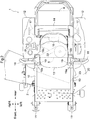
Fig. 2 is a plane view of an electric mower. -
Fig. 3 is a perspective view showing a configuration example of a housing and a gutter member. -
Fig. 4 is an exploded perspective view showing a configuration example of a gutter member. -
Fig. 5 is a perspective view showing a configuration example of a gutter member of another embodiment. - An embodiment of a work vehicle according to the present invention will be described. Unless otherwise specified, the term "front" means forward with respect to the front-rear direction of a vehicle body (traveling direction), and "rear" means rearward with respect to the front-rear direction of the vehicle body (traveling direction) herein. Further, the left-right direction or the lateral direction means the transverse direction of the vehicle body (vehicle body width direction) orthogonal to the front-rear direction of the vehicle body. "Upper" or "lower" is a positional relation with the vertical direction (perpendicular direction) of the vehicle body and means a relation to height above ground level.
- In
Fig.1 andFig.2 , an electric mower is shown as an example of work vehicle. The electric mower includes avehicle body 1, a pair of right and leftfront wheels rear wheels mower unit 2, and abattery storage unit 3. The pair of right and leftfront wheels vehicle body 1, and the pair of right and leftrear wheels vehicle body 1. Themower unit 2 is supported between the pair of right and leftfront wheels rear wheels vehicle body 1. Thebattery storage unit 3 is supported between the pair of right and leftrear wheels vehicle body 1. - The
vehicle body 1 includes aframe 10. A driver'sseat 13, on which a worker sits, aROPS frame 14, and the like are disposed in the upper part of thevehicle body 1. The driver'sseat 13 is supported by theframe 10, and the lower part of theROPS frame 14 is connected to theframe 10. - A pair of right and
left travel motors reduction mechanisms frame 10. Power of thetravel motor 16 on the right side of the machine body (vehicle body 1) is transmitted to therear wheel 12 on the right side of the machine body via the speed-reduction mechanism 17 on the right side of the machine body. Further, power of thetravel motor 16 on the left side of the machine body is transmitted to therear wheel 12 on the left side of the machine body via the speed-reduction mechanism 17 on the left side of the machine body. - A pair of right and
left steering levers seat 13. Eachsteering lever 18 is operated within a range of a predeterminedoperation path 19. Theoperation path 19 consists of an operation path for traveling 19a and an operation path forstop 19b. The operation path for traveling 19a is configured to have a path for operating a speed in moving forward and a path for operating a speed in moving rearward which are arranged in the front-rear direction of the machine body with a neutral position located therebetween at a center. The operation path forstop 19b contacts with the operation path for traveling 19a at the neutral position and is oriented in the left-right direction of the machine body. Regarding the operation path forstop 19b, thesteering lever 18 on the right side of the machine body is operable along the operation path forstop 19b extending from the neutral position to the right side. Thesteering lever 18 on the left side of the machine body is operable along the operation path forstop 19b extending from the neutral position to the left side. When a worker operates thesteering lever 18 on the right side of the machine body to the neutral position, thetravel motor 16 on the right side of the machine body stops. When the worker operates the steeringlever 18 on the right side of the machine body to the moving forward side, thetravel motor 16 on the right side of the machine body rotates in a direction to move the vehicle forward. When the worker operates the steeringlever 18 on the right side of the machine body to the moving rearward side, thetravel motor 16 on the right side of the machine body rotates in a direction to move the vehicle rearward. When the worker shifts the steeringlever 18 on the right side of the machine body from the neutral position to the right side up to the end part of the operation path forstop 19b, a parking brake (corresponding to "brake") of therear wheel 12 on the right side of the machine body becomes a braking state. Also, when the worker operates the steeringlever 18 on the left side of the machine body to the neutral position, the moving forward side, the moving rearward side, and the left end part-side of the operation path forstop 19b, thetravel motor 16 on the left side of the machine body is operated similarly to the above description. With the above, thetravel motor 16 is configured to drive therear wheel 12 as a traveling wheel. That is to say, the worker operates the right and left steering levers 18, 18 independently, thereby driving the respective right and leftrear wheels - The
mower unit 2 includes ahousing unit 20, acutting blade 21, cuttingblade motor 22, and alink mechanism 23. A lower part of thehousing unit 20 is opened downward, and thecutting blade 21 and the cuttingmotor 22 are held in thehousing unit 20. Therefore, the front, rear, left, right and upper sides of thecutting blade 21 are covered with thehousing unit 20. Thecutting blade 21 is rotatable about a vertical axis inside thehousing unit 20 by power of the cuttingmotor 22. Thehousing unit 20 is elevatably suspended from theframe 10 by thelink mechanism 23. - As described above, the
battery storage unit 3 is disposed in the rear part of thevehicle body 1, and thebattery storage unit 3 is configured to hold thebattery unit 4. Thebattery unit 4 is capable of supplying an electric power to thetravel motor 16 and the cuttingmotor 22. Also, the electric mower is equipped with ahousing 5 holding a variety ofparts 15 such as electronic components and circuit boards including various control apparatuses. Any number of thehousings 5 are mounted at any position in thevehicle body 1, for example below the driver'sseat 13 and in thebattery storage unit 3, or the like. - As shown in
Fig. 3 , thehousing 5 has an enclosed space (corresponding to "first enclosed space") surrounded by outercircumferential plates 6, and for example, the outer shape of thehousing 5 is a rectangular parallelepiped composed of the outercircumferential plates 6. The outercircumferential plates 6 include fourside plates 6a, abottom plate 6b, and atop plate 6c. Theside plates 6a are vertically arranged on peripheral parts of an upper face of thebottom plate 6b which is a face on the side of the enclosed space. Thetop plate 6c is arranged on an opposite side to thebottom plate 6b across theside plates 6a, and the peripheral parts of the lower face of thetop plate 6c, which is a face on the side of the enclosed space, contact with theside plates 6a. Thebottom plate 6b serves as the bottom part of thehousing 5 when in use. - A variety of
parts 15 including electronic components such as inverters, relays, and resistances, electric components, harnesses, and others are held in the enclosed space of thehousing 5. - Many of these
parts 15 generate heat, and twoouter holes 8 penetrating through thebottom plate 6b are formed in thebottom plate 6b of thehousing 5 in order to secure ventilation property to theparts 15. - Working machines such as electric mowers are frequently operated outdoors, and occasionally washed with water. The
housing 5 holds a lot ofparts 15 such as electronic components which require waterproof property. Therefore, there is a need to prevent water and the like from entering thehousing 5. As a result, there is a need for thehousing 5 to secure both ventilation property and waterproof property. - The
housing 5 has theouter holes 8, thereby securing ventilation property. However, water may enter the enclosed space of thehousing 5 from theouter holes 8. Therefore, thehousing 5 is equipped with thegutter member 7 surrounding theouter hole 8. - As shown in
Fig. 3 andFig. 4 , thegutter member 7 is disposed in the enclosed space of thehousing 5 while contacting with the outercircumferential plate 6, forming another enclosed space (corresponding to "second enclosed space") by thegutter member 7 and the outercircumferential plates 6. Thegutter member 7 is composed of amain body 7a, twocover plates 7b, and aninner hole 9 formed in themain body 7a. Themain body 7a is disposed over one of theside plates 6a and thebottom plate 6b. Thecover plates 7b are disposed in contact with the respective side faces of themain body 7a, thebottom plate 6b, and theside plate 6a contacting with themain body 7a. With respect to thegutter member 7, the enclosed space is formed by themain body 7a, twocover plates 7b, thebottom plate 6b, and theside plate 6a contacting with themain body 7a. Thegutter member 7 is disposed in thehousing 5 so that the twoouter holes 8 commute with the enclosed space formed by thegutter member 7. Further, themain body 7a is equipped with two connectingparts 7c which are in surface contact with thebottom plate 6b and theside plates 6a respectively. It is preferable to paint the interior of the enclosed space of thehousing 5 in a state of thegutter member 7 being disposed, because, even if there is a minute clearance at the boundary portion between thegutter member 7 and the outercircumferential plate 6, the clearance is filled with a paint and sealability of the enclosed space is improved. - The
inner hole 9 is formed in themain body 7a of thegutter member 7 to penetrate through themain body 7a. In a plane view in which the surface of thebottom plate 6b in the enclosed space is seen from above (on a gutter member 7-side), theinner hole 9 is located on the perpendicular line of thebottom plate 6b which passes near the middle point of the line segment that links the two outer holes 8 (in the drawing, both the distances from the twoouter holes 8 to the middle point are expressed with a character "w"). - With this configuration, ventilation property between the outside of the
housing 5 and the inside of thehousing 5 is secured via theouter holes 8, the enclosed space of thegutter member 7, and theinner hole 9. Also, water entering from theouter holes 8 tends to stay in the enclosed space of thegutter member 7 temporarily without entering the inside of thehousing 5 through theinner hole 9, because theouter holes 8 and theinner hole 9 are provided to be offset. Water in the enclosed space of thegutter member 7 is discharged outside thehousing 5 from at least one of the twoouter holes 8. In particular, since theouter holes 8 are formed in thebottom plate 6b, water hardly enters the inside of thehousing 5 through theinner hole 9 against gravity and tends to be discharged from theouter holes 8 under the influence of gravity. As a result, waterproof property of theparts 15 in thehousing 5 can be effectively secured with the simple configuration. From the above, with the presence of thegutter member 7, ventilation property and waterproof property of thehousing 5 can be secured. -
- (1) The shape of the
inner hole 9 can be a variety of shapes such as round, ellipse, quadrangle, and any polygon forms. For example, as shown inFig. 5 , theinner hole 9 may be a slit (elongated hole) extending along a boundary line between themain body 7a and theside plate 6a. When theinner hole 9 having a constant opening area is supposed, and theinner hole 9 having a round shape and theinner hole 9 having a horizontally long slit are compared, the height of the slit is shorter than the diameter of the round shape, and therefore passing of water through theinner hole 9 is further suppressed and waterproof property can be improved. - (2) In each of the embodiments described above, the
inner hole 9 may be provided at a position offset from all theouter holes 8 in a plane view with respect to the plane parallel to thebottom plate 6b, and may not be near the middle point between theouter holes 8. When theinner hole 9 is provided to be offset from theouter holes 8, water that has entered the enclosed space of thegutter member 7 does not easily enter the inside of thehousing 5 through theinner hole 9, and waterproof property is secured. For example, in a plane view with respect to the plane parallel to thebottom plate 6b, when theouter holes 8 are displaced to one side in the longitudinal direction of thegutter member 7 and theinner hole 9 is displaced to the other side, theinner hole 9 and theouter holes 8 are provided to be offset sufficiently. - (3) In each of the embodiments described above, the number of the provided
outer holes 8 may be three or more, not limited to two. Also, the number of the providedinner holes 9 may be two or more, not limited to one. In such a case, when all theinner holes 9 are provided at positions offset from all theouter holes 8, entering of water into the inside of thehousing 5 is prevented and waterproof property is secured while ventilation property is secured.
Also, by disposing a plurality of theinner holes 9 and making each of theinner holes 9 smaller, passing of water through each of theinner holes 9 becomes difficult and waterproof property is also secured while ventilation property is secured. - (4) In each of the embodiments described above, the
outer holes 8 are provided in thebottom plate 6b, but the positions of theouter holes 8 are not limited to this, and at least one of theouter holes 8 may be provided in theside plates 6a. In such a case, it is preferable that the levels of all theouter holes 8 from thebottom plate 6b are lower than the level of theinner hole 9 from that. By disposing theouter holes 8 at a lower position than theinner hole 9, entering of water into the inside of thehousing 5 is sufficiently prevented and waterproof property is secured. - (5) In each of the embodiments described above, the
gutter member 7 is disposed over one of theside plates 6a and thebottom plate 6b but the plates to which thegutter member 7 is provided are not limited to these, and thegutter member 7 may be disposed over the twoadjacent side plates 6a and thebottom plate 6b. Also, thegutter member 7 may be disposed on only either one of theside plate 6a or thebottom plate 6b. By disposing thegutter member 7 at a desired peripheral part inside thehousing 5, thegutter member 7 can be disposed at an optimal position depending on the arrangement construction of theparts 15, and optimizing the size of thehousing 5 is facilitated. Also, a plurality of thegutter members 7 may be disposed inside thehousing 5. By disposing a plurality ofgutter members 7, ventilation property of thehousing 5 can be improved while waterproof property is secured.
Claims (7)
- A housing for holding parts comprising:a plurality of outer circumferential plates (6) connected with each other to form a first enclosed space, one or more of the outer circumferential plates (6) having a total of two or more outer holes (8) formed therein; anda gutter member (7) connected to at least two outer circumferential plates (6), the gutter member (7) having an inner hole (9) formed therein;wherein the outer circumferential plates (6) and the gutter member (7) form a second enclosed space,the outer holes (8) communicate with the second enclosed space, andthe inner hole (9) is provided to be offset from the lines passing through the respective outer holes (8), the lines being perpendicular to the outer circumferential plate in which the outer holes (8) are formed.
- The housing according to claim 1, wherein the outer holes (8) are formed in the outer circumferential plate which serves as a bottom plate when the housing is in use.
- The housing according to claim 1 or 2, wherein the gutter member (7) is disposed over two adjacent outer circumferential plates (6).
- The housing according to any one of claims 1 to 3, wherein the outer holes (8) are two holes provided in one of the outer circumferential plates (6), and
the inner hole (9) is provided near a middle point between the two outer holes (8) when viewed from a plane parallel to the outer circumferential plate in which the outer holes (8) are formed. - The housing according to any one of claims 1 to 4, wherein the inner hole (9) is an elongated hole along a contacting line between the outer circumferential plate and the gutter member (7).
- The housing according to any one of claims 1 to 5, wherein a plurality of the gutter members (7) are provided to form the respective second enclosed spaces, the outer holes (8) communicate with the respective second enclosed spaces and the inner holes (9) communicate with the respective second enclosed spaces.
- An electric mower comprising the housing according to any one of claims 1 to 6.
Applications Claiming Priority (1)
| Application Number | Priority Date | Filing Date | Title |
|---|---|---|---|
| JP2019163700A JP7264778B2 (en) | 2019-09-09 | 2019-09-09 | Enclosure and electric lawn mower |
Publications (2)
| Publication Number | Publication Date |
|---|---|
| EP3788857A1 true EP3788857A1 (en) | 2021-03-10 |
| EP3788857B1 EP3788857B1 (en) | 2025-06-25 |
Family
ID=71401546
Family Applications (1)
| Application Number | Title | Priority Date | Filing Date |
|---|---|---|---|
| EP20179008.6A Active EP3788857B1 (en) | 2019-09-09 | 2020-06-09 | Housing and electric mower |
Country Status (3)
| Country | Link |
|---|---|
| US (1) | US11589505B2 (en) |
| EP (1) | EP3788857B1 (en) |
| JP (1) | JP7264778B2 (en) |
Families Citing this family (1)
| Publication number | Priority date | Publication date | Assignee | Title |
|---|---|---|---|---|
| EP4454916A4 (en) * | 2021-12-24 | 2026-04-01 | Kubota Kk | ELECTRIC WORK VEHICLE |
Citations (4)
| Publication number | Priority date | Publication date | Assignee | Title |
|---|---|---|---|---|
| JP2000295721A (en) | 1999-04-02 | 2000-10-20 | Hitachi Service & Engineering (East) Ltd | Control panel waterproof structure |
| US20060087210A1 (en) * | 2004-10-25 | 2006-04-27 | Samsung Sdi Co., Ltd. | Plasma display apparatus |
| EP3333934A1 (en) * | 2015-10-28 | 2018-06-13 | Murata Manufacturing Co., Ltd. | Electric device case and battery pack provided with same |
| WO2018116715A1 (en) * | 2016-12-23 | 2018-06-28 | 本田技研工業株式会社 | Battery pack |
Family Cites Families (8)
| Publication number | Priority date | Publication date | Assignee | Title |
|---|---|---|---|---|
| JP5773412B2 (en) * | 2011-03-31 | 2015-09-02 | Necエナジーデバイス株式会社 | Battery pack and electric bicycle |
| JP5921199B2 (en) * | 2012-01-05 | 2016-05-24 | 三菱電機株式会社 | Light source device |
| US9911951B2 (en) * | 2014-09-30 | 2018-03-06 | Johnson Controls Technology Company | Battery module compressed cell assembly |
| JP5973521B2 (en) * | 2014-10-15 | 2016-08-23 | 株式会社クボタ | Optical grain evaluation system |
| JP6506942B2 (en) * | 2014-10-23 | 2019-04-24 | 日東電工株式会社 | Insulation and battery cover |
| JP6662395B2 (en) * | 2016-01-15 | 2020-03-11 | 株式会社村田製作所 | Battery pack |
| EP3509130B1 (en) * | 2016-10-03 | 2022-02-23 | Murata Manufacturing Co., Ltd. | Battery pack, electronic apparatus, electric vehicle, electric tool, and power storage system |
| JP7359527B2 (en) * | 2017-05-31 | 2023-10-11 | トヨタ自動車株式会社 | Battery mounting structure |
-
2019
- 2019-09-09 JP JP2019163700A patent/JP7264778B2/en active Active
-
2020
- 2020-06-08 US US16/895,591 patent/US11589505B2/en active Active
- 2020-06-09 EP EP20179008.6A patent/EP3788857B1/en active Active
Patent Citations (5)
| Publication number | Priority date | Publication date | Assignee | Title |
|---|---|---|---|---|
| JP2000295721A (en) | 1999-04-02 | 2000-10-20 | Hitachi Service & Engineering (East) Ltd | Control panel waterproof structure |
| US20060087210A1 (en) * | 2004-10-25 | 2006-04-27 | Samsung Sdi Co., Ltd. | Plasma display apparatus |
| EP3333934A1 (en) * | 2015-10-28 | 2018-06-13 | Murata Manufacturing Co., Ltd. | Electric device case and battery pack provided with same |
| WO2018116715A1 (en) * | 2016-12-23 | 2018-06-28 | 本田技研工業株式会社 | Battery pack |
| EP3561901A1 (en) * | 2016-12-23 | 2019-10-30 | Honda Motor Co., Ltd. | Battery pack |
Also Published As
| Publication number | Publication date |
|---|---|
| US20210068341A1 (en) | 2021-03-11 |
| US11589505B2 (en) | 2023-02-28 |
| JP7264778B2 (en) | 2023-04-25 |
| EP3788857B1 (en) | 2025-06-25 |
| JP2021040505A (en) | 2021-03-18 |
Similar Documents
| Publication | Publication Date | Title |
|---|---|---|
| EP3078526B1 (en) | Electric work vehicle | |
| DE102020200394B4 (en) | VEHICLE | |
| JP7814140B2 (en) | electric tractor | |
| JP6461683B2 (en) | Electric work vehicle | |
| JP6727861B2 (en) | Riding electric mower | |
| EP3117695B1 (en) | Grass mower | |
| JP5684768B2 (en) | Work vehicle | |
| US10499565B2 (en) | Grass mower machine | |
| EP2765242B1 (en) | Small-sized hydraulic excavator | |
| EP4129730B1 (en) | Electric construction machine | |
| DE112018007195B4 (en) | STRAT-SEAT ELECTRIC VEHICLE | |
| JP6752258B2 (en) | vehicle | |
| JP2013174044A (en) | Cab for work vehicle, and work vehicle | |
| EP3788857B1 (en) | Housing and electric mower | |
| CN110893758A (en) | vehicle | |
| KR102493699B1 (en) | work car | |
| JP2018196355A (en) | Mower unit | |
| JP2007331719A (en) | High piezoelectric equipment installation structure | |
| JP6498975B2 (en) | Working vehicle | |
| JP2005146741A (en) | Cab and work machine | |
| JP5183822B1 (en) | Work vehicle cab and work vehicle | |
| US20240286495A1 (en) | Electric work vehicle | |
| JP2020026219A (en) | Vehicle front structure | |
| US10272760B2 (en) | Work vehicle | |
| US20240423133A1 (en) | Electric mower |
Legal Events
| Date | Code | Title | Description |
|---|---|---|---|
| PUAI | Public reference made under article 153(3) epc to a published international application that has entered the european phase |
Free format text: ORIGINAL CODE: 0009012 |
|
| STAA | Information on the status of an ep patent application or granted ep patent |
Free format text: STATUS: REQUEST FOR EXAMINATION WAS MADE |
|
| 17P | Request for examination filed |
Effective date: 20200609 |
|
| AK | Designated contracting states |
Kind code of ref document: A1 Designated state(s): AL AT BE BG CH CY CZ DE DK EE ES FI FR GB GR HR HU IE IS IT LI LT LU LV MC MK MT NL NO PL PT RO RS SE SI SK SM TR |
|
| AX | Request for extension of the european patent |
Extension state: BA ME |
|
| STAA | Information on the status of an ep patent application or granted ep patent |
Free format text: STATUS: EXAMINATION IS IN PROGRESS |
|
| 17Q | First examination report despatched |
Effective date: 20230202 |
|
| GRAP | Despatch of communication of intention to grant a patent |
Free format text: ORIGINAL CODE: EPIDOSNIGR1 |
|
| STAA | Information on the status of an ep patent application or granted ep patent |
Free format text: STATUS: GRANT OF PATENT IS INTENDED |
|
| RIC1 | Information provided on ipc code assigned before grant |
Ipc: H05K 7/14 20060101ALI20250312BHEP Ipc: H05K 5/02 20060101ALI20250312BHEP Ipc: A01D 69/02 20060101ALI20250312BHEP Ipc: A01D 34/81 20060101AFI20250312BHEP |
|
| INTG | Intention to grant announced |
Effective date: 20250328 |
|
| GRAS | Grant fee paid |
Free format text: ORIGINAL CODE: EPIDOSNIGR3 |
|
| GRAA | (expected) grant |
Free format text: ORIGINAL CODE: 0009210 |
|
| STAA | Information on the status of an ep patent application or granted ep patent |
Free format text: STATUS: THE PATENT HAS BEEN GRANTED |
|
| AK | Designated contracting states |
Kind code of ref document: B1 Designated state(s): AL AT BE BG CH CY CZ DE DK EE ES FI FR GB GR HR HU IE IS IT LI LT LU LV MC MK MT NL NO PL PT RO RS SE SI SK SM TR |
|
| REG | Reference to a national code |
Ref country code: GB Ref legal event code: FG4D |
|
| REG | Reference to a national code |
Ref country code: CH Ref legal event code: EP |
|
| REG | Reference to a national code |
Ref country code: CH Ref legal event code: EP |
|
| REG | Reference to a national code |
Ref country code: IE Ref legal event code: FG4D |
|
| REG | Reference to a national code |
Ref country code: DE Ref legal event code: R096 Ref document number: 602020053186 Country of ref document: DE |
|
| PG25 | Lapsed in a contracting state [announced via postgrant information from national office to epo] |
Ref country code: FI Free format text: LAPSE BECAUSE OF FAILURE TO SUBMIT A TRANSLATION OF THE DESCRIPTION OR TO PAY THE FEE WITHIN THE PRESCRIBED TIME-LIMIT Effective date: 20250625 |
|
| REG | Reference to a national code |
Ref country code: LT Ref legal event code: MG9D |
|
| PG25 | Lapsed in a contracting state [announced via postgrant information from national office to epo] |
Ref country code: NO Free format text: LAPSE BECAUSE OF FAILURE TO SUBMIT A TRANSLATION OF THE DESCRIPTION OR TO PAY THE FEE WITHIN THE PRESCRIBED TIME-LIMIT Effective date: 20250925 Ref country code: GR Free format text: LAPSE BECAUSE OF FAILURE TO SUBMIT A TRANSLATION OF THE DESCRIPTION OR TO PAY THE FEE WITHIN THE PRESCRIBED TIME-LIMIT Effective date: 20250926 |
|
| PG25 | Lapsed in a contracting state [announced via postgrant information from national office to epo] |
Ref country code: BG Free format text: LAPSE BECAUSE OF FAILURE TO SUBMIT A TRANSLATION OF THE DESCRIPTION OR TO PAY THE FEE WITHIN THE PRESCRIBED TIME-LIMIT Effective date: 20250625 |
|
| PG25 | Lapsed in a contracting state [announced via postgrant information from national office to epo] |
Ref country code: HR Free format text: LAPSE BECAUSE OF FAILURE TO SUBMIT A TRANSLATION OF THE DESCRIPTION OR TO PAY THE FEE WITHIN THE PRESCRIBED TIME-LIMIT Effective date: 20250625 |
|
| PG25 | Lapsed in a contracting state [announced via postgrant information from national office to epo] |
Ref country code: RS Free format text: LAPSE BECAUSE OF FAILURE TO SUBMIT A TRANSLATION OF THE DESCRIPTION OR TO PAY THE FEE WITHIN THE PRESCRIBED TIME-LIMIT Effective date: 20250925 |
|
| PG25 | Lapsed in a contracting state [announced via postgrant information from national office to epo] |
Ref country code: LV Free format text: LAPSE BECAUSE OF FAILURE TO SUBMIT A TRANSLATION OF THE DESCRIPTION OR TO PAY THE FEE WITHIN THE PRESCRIBED TIME-LIMIT Effective date: 20250625 |
|
| REG | Reference to a national code |
Ref country code: NL Ref legal event code: MP Effective date: 20250625 |
|
| PG25 | Lapsed in a contracting state [announced via postgrant information from national office to epo] |
Ref country code: NL Free format text: LAPSE BECAUSE OF FAILURE TO SUBMIT A TRANSLATION OF THE DESCRIPTION OR TO PAY THE FEE WITHIN THE PRESCRIBED TIME-LIMIT Effective date: 20250625 |
|
| PG25 | Lapsed in a contracting state [announced via postgrant information from national office to epo] |
Ref country code: PT Free format text: LAPSE BECAUSE OF FAILURE TO SUBMIT A TRANSLATION OF THE DESCRIPTION OR TO PAY THE FEE WITHIN THE PRESCRIBED TIME-LIMIT Effective date: 20251027 |
|
| REG | Reference to a national code |
Ref country code: AT Ref legal event code: MK05 Ref document number: 1805445 Country of ref document: AT Kind code of ref document: T Effective date: 20250625 |
|
| PG25 | Lapsed in a contracting state [announced via postgrant information from national office to epo] |
Ref country code: IS Free format text: LAPSE BECAUSE OF FAILURE TO SUBMIT A TRANSLATION OF THE DESCRIPTION OR TO PAY THE FEE WITHIN THE PRESCRIBED TIME-LIMIT Effective date: 20251025 |
|
| PG25 | Lapsed in a contracting state [announced via postgrant information from national office to epo] |
Ref country code: AT Free format text: LAPSE BECAUSE OF FAILURE TO SUBMIT A TRANSLATION OF THE DESCRIPTION OR TO PAY THE FEE WITHIN THE PRESCRIBED TIME-LIMIT Effective date: 20250625 Ref country code: SM Free format text: LAPSE BECAUSE OF FAILURE TO SUBMIT A TRANSLATION OF THE DESCRIPTION OR TO PAY THE FEE WITHIN THE PRESCRIBED TIME-LIMIT Effective date: 20250625 |
|
| PG25 | Lapsed in a contracting state [announced via postgrant information from national office to epo] |
Ref country code: CZ Free format text: LAPSE BECAUSE OF FAILURE TO SUBMIT A TRANSLATION OF THE DESCRIPTION OR TO PAY THE FEE WITHIN THE PRESCRIBED TIME-LIMIT Effective date: 20250625 |
|
| PG25 | Lapsed in a contracting state [announced via postgrant information from national office to epo] |
Ref country code: PL Free format text: LAPSE BECAUSE OF FAILURE TO SUBMIT A TRANSLATION OF THE DESCRIPTION OR TO PAY THE FEE WITHIN THE PRESCRIBED TIME-LIMIT Effective date: 20250625 |
|
| PG25 | Lapsed in a contracting state [announced via postgrant information from national office to epo] |
Ref country code: EE Free format text: LAPSE BECAUSE OF FAILURE TO SUBMIT A TRANSLATION OF THE DESCRIPTION OR TO PAY THE FEE WITHIN THE PRESCRIBED TIME-LIMIT Effective date: 20250625 |
|
| PG25 | Lapsed in a contracting state [announced via postgrant information from national office to epo] |
Ref country code: SK Free format text: LAPSE BECAUSE OF FAILURE TO SUBMIT A TRANSLATION OF THE DESCRIPTION OR TO PAY THE FEE WITHIN THE PRESCRIBED TIME-LIMIT Effective date: 20250625 |
|
| PG25 | Lapsed in a contracting state [announced via postgrant information from national office to epo] |
Ref country code: ES Free format text: LAPSE BECAUSE OF FAILURE TO SUBMIT A TRANSLATION OF THE DESCRIPTION OR TO PAY THE FEE WITHIN THE PRESCRIBED TIME-LIMIT Effective date: 20250625 |
|
| PG25 | Lapsed in a contracting state [announced via postgrant information from national office to epo] |
Ref country code: DK Free format text: LAPSE BECAUSE OF FAILURE TO SUBMIT A TRANSLATION OF THE DESCRIPTION OR TO PAY THE FEE WITHIN THE PRESCRIBED TIME-LIMIT Effective date: 20250625 |
|
| PG25 | Lapsed in a contracting state [announced via postgrant information from national office to epo] |
Ref country code: IT Free format text: LAPSE BECAUSE OF FAILURE TO SUBMIT A TRANSLATION OF THE DESCRIPTION OR TO PAY THE FEE WITHIN THE PRESCRIBED TIME-LIMIT Effective date: 20250625 |
|
| PLBE | No opposition filed within time limit |
Free format text: ORIGINAL CODE: 0009261 |
|
| STAA | Information on the status of an ep patent application or granted ep patent |
Free format text: STATUS: NO OPPOSITION FILED WITHIN TIME LIMIT |
|
| REG | Reference to a national code |
Ref country code: CH Ref legal event code: L10 Free format text: ST27 STATUS EVENT CODE: U-0-0-L10-L00 (AS PROVIDED BY THE NATIONAL OFFICE) Effective date: 20260507 |