EP3788361B1 - Dual frequency ultrasound transducer - Google Patents
Dual frequency ultrasound transducer Download PDFInfo
- Publication number
- EP3788361B1 EP3788361B1 EP19796200.4A EP19796200A EP3788361B1 EP 3788361 B1 EP3788361 B1 EP 3788361B1 EP 19796200 A EP19796200 A EP 19796200A EP 3788361 B1 EP3788361 B1 EP 3788361B1
- Authority
- EP
- European Patent Office
- Prior art keywords
- frequency transducer
- high frequency
- low frequency
- transducer elements
- dual
- Prior art date
- Legal status (The legal status is an assumption and is not a legal conclusion. Google has not performed a legal analysis and makes no representation as to the accuracy of the status listed.)
- Active
Links
Images




Classifications
-
- G—PHYSICS
- G01—MEASURING; TESTING
- G01S—RADIO DIRECTION-FINDING; RADIO NAVIGATION; DETERMINING DISTANCE OR VELOCITY BY USE OF RADIO WAVES; LOCATING OR PRESENCE-DETECTING BY USE OF THE REFLECTION OR RERADIATION OF RADIO WAVES; ANALOGOUS ARRANGEMENTS USING OTHER WAVES
- G01S7/00—Details of systems according to groups G01S13/00, G01S15/00, G01S17/00
- G01S7/52—Details of systems according to groups G01S13/00, G01S15/00, G01S17/00 of systems according to group G01S15/00
- G01S7/52017—Details of systems according to groups G01S13/00, G01S15/00, G01S17/00 of systems according to group G01S15/00 particularly adapted to short-range imaging
- G01S7/52079—Constructional features
-
- B—PERFORMING OPERATIONS; TRANSPORTING
- B06—GENERATING OR TRANSMITTING MECHANICAL VIBRATIONS IN GENERAL
- B06B—METHODS OR APPARATUS FOR GENERATING OR TRANSMITTING MECHANICAL VIBRATIONS OF INFRASONIC, SONIC, OR ULTRASONIC FREQUENCY, e.g. FOR PERFORMING MECHANICAL WORK IN GENERAL
- B06B1/00—Methods or apparatus for generating mechanical vibrations of infrasonic, sonic, or ultrasonic frequency
- B06B1/02—Methods or apparatus for generating mechanical vibrations of infrasonic, sonic, or ultrasonic frequency making use of electrical energy
- B06B1/06—Methods or apparatus for generating mechanical vibrations of infrasonic, sonic, or ultrasonic frequency making use of electrical energy operating with piezoelectric effect or with electrostriction
- B06B1/0607—Methods or apparatus for generating mechanical vibrations of infrasonic, sonic, or ultrasonic frequency making use of electrical energy operating with piezoelectric effect or with electrostriction using multiple elements
- B06B1/0622—Methods or apparatus for generating mechanical vibrations of infrasonic, sonic, or ultrasonic frequency making use of electrical energy operating with piezoelectric effect or with electrostriction using multiple elements on one surface
-
- G—PHYSICS
- G01—MEASURING; TESTING
- G01S—RADIO DIRECTION-FINDING; RADIO NAVIGATION; DETERMINING DISTANCE OR VELOCITY BY USE OF RADIO WAVES; LOCATING OR PRESENCE-DETECTING BY USE OF THE REFLECTION OR RERADIATION OF RADIO WAVES; ANALOGOUS ARRANGEMENTS USING OTHER WAVES
- G01S15/00—Systems using the reflection or reradiation of acoustic waves, e.g. sonar systems
- G01S15/88—Sonar systems specially adapted for specific applications
- G01S15/89—Sonar systems specially adapted for specific applications for mapping or imaging
- G01S15/8906—Short-range imaging systems; Acoustic microscope systems using pulse-echo techniques
- G01S15/8909—Short-range imaging systems; Acoustic microscope systems using pulse-echo techniques using a static transducer configuration
- G01S15/8915—Short-range imaging systems; Acoustic microscope systems using pulse-echo techniques using a static transducer configuration using a transducer array
-
- G—PHYSICS
- G01—MEASURING; TESTING
- G01S—RADIO DIRECTION-FINDING; RADIO NAVIGATION; DETERMINING DISTANCE OR VELOCITY BY USE OF RADIO WAVES; LOCATING OR PRESENCE-DETECTING BY USE OF THE REFLECTION OR RERADIATION OF RADIO WAVES; ANALOGOUS ARRANGEMENTS USING OTHER WAVES
- G01S15/00—Systems using the reflection or reradiation of acoustic waves, e.g. sonar systems
- G01S15/88—Sonar systems specially adapted for specific applications
- G01S15/89—Sonar systems specially adapted for specific applications for mapping or imaging
- G01S15/8906—Short-range imaging systems; Acoustic microscope systems using pulse-echo techniques
- G01S15/895—Short-range imaging systems; Acoustic microscope systems using pulse-echo techniques characterised by the transmitted frequency spectrum
- G01S15/8952—Short-range imaging systems; Acoustic microscope systems using pulse-echo techniques characterised by the transmitted frequency spectrum using discrete, multiple frequencies
-
- G—PHYSICS
- G01—MEASURING; TESTING
- G01S—RADIO DIRECTION-FINDING; RADIO NAVIGATION; DETERMINING DISTANCE OR VELOCITY BY USE OF RADIO WAVES; LOCATING OR PRESENCE-DETECTING BY USE OF THE REFLECTION OR RERADIATION OF RADIO WAVES; ANALOGOUS ARRANGEMENTS USING OTHER WAVES
- G01S15/00—Systems using the reflection or reradiation of acoustic waves, e.g. sonar systems
- G01S15/88—Sonar systems specially adapted for specific applications
- G01S15/89—Sonar systems specially adapted for specific applications for mapping or imaging
- G01S15/8906—Short-range imaging systems; Acoustic microscope systems using pulse-echo techniques
- G01S15/895—Short-range imaging systems; Acoustic microscope systems using pulse-echo techniques characterised by the transmitted frequency spectrum
- G01S15/8956—Short-range imaging systems; Acoustic microscope systems using pulse-echo techniques characterised by the transmitted frequency spectrum using frequencies at or above 20 MHz
-
- G—PHYSICS
- G01—MEASURING; TESTING
- G01S—RADIO DIRECTION-FINDING; RADIO NAVIGATION; DETERMINING DISTANCE OR VELOCITY BY USE OF RADIO WAVES; LOCATING OR PRESENCE-DETECTING BY USE OF THE REFLECTION OR RERADIATION OF RADIO WAVES; ANALOGOUS ARRANGEMENTS USING OTHER WAVES
- G01S15/00—Systems using the reflection or reradiation of acoustic waves, e.g. sonar systems
- G01S15/88—Sonar systems specially adapted for specific applications
- G01S15/89—Sonar systems specially adapted for specific applications for mapping or imaging
- G01S15/8906—Short-range imaging systems; Acoustic microscope systems using pulse-echo techniques
- G01S15/8979—Combined Doppler and pulse-echo imaging systems
-
- A—HUMAN NECESSITIES
- A61—MEDICAL OR VETERINARY SCIENCE; HYGIENE
- A61B—DIAGNOSIS; SURGERY; IDENTIFICATION
- A61B8/00—Diagnosis using ultrasonic, sonic or infrasonic waves
- A61B8/44—Constructional features of the ultrasonic, sonic or infrasonic diagnostic device
- A61B8/4483—Constructional features of the ultrasonic, sonic or infrasonic diagnostic device characterised by features of the ultrasound transducer
- A61B8/4494—Constructional features of the ultrasonic, sonic or infrasonic diagnostic device characterised by features of the ultrasound transducer characterised by the arrangement of the transducer elements
-
- A—HUMAN NECESSITIES
- A61—MEDICAL OR VETERINARY SCIENCE; HYGIENE
- A61B—DIAGNOSIS; SURGERY; IDENTIFICATION
- A61B8/00—Diagnosis using ultrasonic, sonic or infrasonic waves
- A61B8/48—Diagnostic techniques
- A61B8/481—Diagnostic techniques involving the use of contrast agents, e.g. microbubbles introduced into the bloodstream
-
- B—PERFORMING OPERATIONS; TRANSPORTING
- B06—GENERATING OR TRANSMITTING MECHANICAL VIBRATIONS IN GENERAL
- B06B—METHODS OR APPARATUS FOR GENERATING OR TRANSMITTING MECHANICAL VIBRATIONS OF INFRASONIC, SONIC, OR ULTRASONIC FREQUENCY, e.g. FOR PERFORMING MECHANICAL WORK IN GENERAL
- B06B2201/00—Indexing scheme associated with B06B1/0207 for details covered by B06B1/0207 but not provided for in any of its subgroups
- B06B2201/70—Specific application
- B06B2201/76—Medical, dental
-
- G—PHYSICS
- G01—MEASURING; TESTING
- G01S—RADIO DIRECTION-FINDING; RADIO NAVIGATION; DETERMINING DISTANCE OR VELOCITY BY USE OF RADIO WAVES; LOCATING OR PRESENCE-DETECTING BY USE OF THE REFLECTION OR RERADIATION OF RADIO WAVES; ANALOGOUS ARRANGEMENTS USING OTHER WAVES
- G01S7/00—Details of systems according to groups G01S13/00, G01S15/00, G01S17/00
- G01S7/52—Details of systems according to groups G01S13/00, G01S15/00, G01S17/00 of systems according to group G01S15/00
- G01S7/52017—Details of systems according to groups G01S13/00, G01S15/00, G01S17/00 of systems according to group G01S15/00 particularly adapted to short-range imaging
- G01S7/52023—Details of receivers
- G01S7/52036—Details of receivers using analysis of echo signal for target characterisation
- G01S7/52038—Details of receivers using analysis of echo signal for target characterisation involving non-linear properties of the propagation medium or of the reflective target
Definitions
- the disclosed technology relates to ultrasound transducers and in particular to dual frequency ultrasound transducers.
- ultrasonic acoustic signals are directed towards a region of interest and the corresponding reflected echo signals are detected.
- Characteristics of the echo signals such as their amplitude, phase shift, Doppler shift, power etc. are analyzed and quantified into pixel data that are used to create an image of or representation of flow.
- the received ultrasound echo signals are in the same frequency range as the transmitted ultrasound signals.
- harmonic imaging Another approach to performing ultrasound imaging is to apply ultrasonic acoustic signals to the region of interest at one frequency and to capture and analyze the received echo signals at another frequency such as at one or more harmonics of the transmitted ultrasound signals.
- the harmonics typically have a frequency that is 3-5 times that of the transmitted signals.
- Contrast agents are generally fluid or lipid encapsulated microbubbles that are sized to resonate at a particular transmitted ultrasound frequency. Exposure to ultrasound in the body at the resonant frequency of the microbubbles, causes the bubbles to rupture and produce non-linear ultrasound echoes having a much higher frequency than the applied ultrasound.
- non-linear microbubbles can be designed to resonate at 1-6 MHz but produce echo signals in the range of 10-30 MHz.
- the high frequency echo signals allow detailed images of tissue structures to be produced and studied such as the micro-vasculature surrounding tumors in clinical or pre-clinical settings.
- the most conventional way of performing dual frequency imaging is with a mechanically scanned, single element transducer having confocal low and high frequency transducer elements. While such transducers work well, faster scanning can be performed with transducer arrays that can be electronically steered. Such transducers generally have a low frequency transducer array and a high frequency transducer array that are aligned with each other.
- One problem with dual frequency transducers is aligning the low and high frequency arrays.
- the element size e.g. 1/2 A or less
- the element size is approximately 15 microns.
- a typical human hair is approximately 80 microns in diameter.
- the procedure required to align the arrays often requires making micro-adjustments to the position of the high and low frequency transducers on a wet bench and then adhering them together when the best match is found. This is both time consuming and costly.
- the technology discussed herein relates to an improved dual frequency transducer that is easier and/or less costly to manufacture.
- US 2017/282215 teaches a dual frequency ultrasound transducer having a low frequency ultrasound array positioned behind a high frequency ultrasound array, and a dampening material for attenuating high frequency signals positioned between the high frequency and low frequency arrays.
- US 8674524 teaches a semiconductor device having alignment markings on a layer of the device for use in aligning the layer with other layers of the device.
- US 2013/207519 discloses an ultrasound transducer that includes alignment markers on a bottom surface of a piezoelectric layer for use in correctly orienting the piezoelectric layer with respect to a flex circuit.
- the invention provides a dual frequency transducer comprising: a high frequency (HF) transducer comprising a sheet of PZT material including a number of HF transducer elements, one or more matching layers, a lens positioned in front of the HF transducer elements and a support frame on a back side of the PZT material that supports one or more flex circuits with signal traces that connect to the HF transducer elements; an intermediate layer that is configured to absorb HF ultrasound signals and positioned behind the HF transducer elements; and a low frequency (LF) transducer; characterised in that the dual frequency transducer comprises one or more fiducials placed at known positions with respect to the HF transducer elements; and the LF transducer includes a sheet of PZT material including a number of LF transducer elements, one or more matching layers and a flex circuit with signal traces that connect to the LF transducer elements, wherein the LF transducer includes one or more alignment tabs with an alignment feature
- the support frame may include an alignment post that fits with a cooperating slot or keyway on the intermediate layer to align the intermediate layer with the support frame and the high frequency transducer elements.
- One or more fiducials on the intermediate layer may be positioned at locations referenced to the high frequency transducer elements to align the low frequency transducer to the high frequency transducer elements.
- the invention provides a dual frequency transducer comprising: a high frequency (HF) transducer comprising a sheet of PZT material including a number of HF transducer elements; a backing material that is constructed to absorb HF ultrasound signals and pass low frequency (LF) ultrasound signals; and a low frequency (LF) transducer; characterised in that the dual frequency transducer comprises one or more fiducials placed at known positions with respect to the HF transducer elements; and the LF transducer includes a number of LF transducer elements including one or more alignment tabs that are positioned using the one or more fiducials to align the LF transducer elements with the HF transducer elements.
- HF high frequency
- LF low frequency
- Figure 1 is a top view of a piezoelectric layer 50 for a high frequency ultrasound transducer in accordance with one embodiment of the disclosed technology.
- the layer 50 has an outer frame 52 that surrounds a sheet 54 of PZT, single crystal piezoelectric or other known piezoelectric material.
- the frame 52 is a pre-machined, non-conductive alumina ceramic with a center cut out area that is slightly larger than the outer dimensions of the sheet 54 of piezoelectric material.
- the frame 52 can be made of a conductive material such as molybdenum or graphite.
- the frame 52 preferably has a coefficient of thermal expansion that is similar to that of the piezoelectric material so that the piezoelectric material doesn't crack during manufacture, handling or use.
- An adhesive 56 such as EPO-TEK 301 epoxy fills a gap between the frame and the piezoelectric material.
- the piezoelectric material 54 is diced with a patterning laser or a dicing saw to create a number (e.g. 128, 256 or fewer or a larger number) of piezoelectric elements (not separately shown). By surrounding the sheet 54 of piezoelectric material with the frame 52, the kerf cuts that define the individual transducer elements can extend across the entire width of the sheet of piezoelectric material.
- a cut-out area or notch 60 on one or both sides of the frame is filled with a conductive epoxy or can include a number of conductive vias to provide an electrical path from a front surface of the frame to a rear surface of the frame. More details about the construction of an ultrasound transducer with a surrounding frame can be found in commonly-owned U.S. Patent Publication No. 2019/0200959 filed May 30, 2018 and International Publication No. 2019/133271 .
- Figure 1B shows a piezoelectric layer 70 of a low frequency ultrasound transducer that in one embodiment, is constructed in the same manner as the piezoelectric layer of the high frequency transducer shown in Figure 1A .
- An alumina frame 72 surrounds a sheet 74 of piezoelectric material.
- the frame 72 has a central opening that is sized to form a gap between the edges of the opening and the edges of the piezoelectric sheet 74.
- the gap is filled with a non-conductive epoxy 76.
- the low frequency array has fewer transducer elements than the high frequency transducer. In one embodiment, the low frequency transducer has 32 individually addressable transducer elements but could have fewer or more elements.
- a pair of cut-out areas or notches 80 on either side of the frame 72 can be filled with a conductive epoxy or can include conductive vies through the frame to provide an electrical path from a front surface of the low frequency array to the rear surface of the frame.
- Figure 2 is an isometric view of a conductive support frame 100 that is to be secured to a rear surface of the piezoelectric layer 50 of the high frequency transducer.
- the frame 100 supports one or more flex circuits (not shown) having signal traces therein that are electrically connected to corresponding electrodes on each of the high frequency transducer elements.
- the support frame 100 provides electromagnetic shielding for the rear surface of the transducer elements.
- a common ground electrode on the front surface of the piezoelectric layer 50 is connected to a ground plane in the flex circuits via a conductive path that includes the conductive support frame 100.
- the support frame 100 is secured to the piezoelectric layer 50 with a conductive epoxy.
- Also shown in Figure 2 are one or more matching layers and a lens that are positioned ahead of (e.g. in front of) the piezoelectric layer 50.
- Figure 3 shows one flex circuit 104 attached to the support frame 100.
- the high frequency transducer includes two flex circuits with the signal traces of one flex circuit electrically coupled to the even numbered transducer elements and the signal traces of the other flex circuit electrically connected to the odd numbered transducer elements. Electrical connections are made from the individual transducer elements on the rear surface of the piezoelectric layer to the metal signal traces in the flex circuits. Connections between the transducer elements and the metal signal traces in the flex circuits can be made using the techniques described in U.S. Patent Publication No. 2017/0144192 or U.S. Patent No. 8,316,518 .
- an open back side of the support frame is filled with an epoxy material 110 such as EPO-TEK 301.
- the height of the epoxy 110 in the frame extends above the rim of the support frame 100.
- the epoxy 110 is molded or laser machined to form a pair of alignment posts 112a, 112b and a recess area 114 that is behind the high frequency transducer elements.
- the depth of the recess area 114 is about 4.2 mm.
- the alignment posts 112a, 112b are configured to align an intermediate layer over the high frequency transducer as will be described below.
- a pair of fiducials 120a, 120b are marked with a laser on each alignment post at a known distance from the high frequency transducer elements.
- the fiducials 120a, 120b serve as a reference so that other components of the dual frequency transducer can be placed at known positions with respect to the high frequency transducer elements.
- Figure 4 illustrates one embodiment of an intermediate layer 150 that is placed behind the high frequency transducer.
- the intermediate layer 150 is made of silicone powder-doped EPO-TEK 301 epoxy.
- the size of the silicone powder is in the nanometer range such that it highly attenuates high frequency (HF) ultrasound and passes low frequency (LF) ultrasound.
- the intermediate layer is sized to absorb high frequency ultrasound to a specified level, such as 65 dB, but to pass low frequency signals transmitted from, or to be received by, the low frequency transducer.
- the top of the intermediate layer 150 includes a pair of slots or keyways 152a, 152b that cooperate with the alignment posts 112a, 112b on the back side of the frame 100 to align the intermediate layer 150 at a known position with respect to transducer elements of the high frequency transducer.
- the intermediate layer 150 is secured to the frame 100 using the same epoxy that fills the back side of the frame to avoid acoustic discontinuities at the bond line.
- additional fiducials 154a, 154b can be placed on the intermediate layer as measured from the fiducials 120a, 120b that are marked on the support frame (i.e. on the filler epoxy at the back side of the support frame).
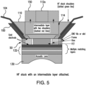
- FIG. 5 shows a cross section of the high frequency transducer with the intermediate layer 150 secured to the back of the support frame 100.
- the high frequency transducer comprises a lens 130 designed to focus the high frequency ultrasound signals at a specific depth.
- Typical lens materials include polymethylpentene (tradename TPX), cross-linked polystyrene (tradename Rexolite) or polybenzimidazone (tradename Celezole).
- TPX polymethylpentene
- Rexolite cross-linked polystyrene
- Celezole polybenzimidazone
- other non-attenuating plastic materials could also be used.
- Behind the lens are one or more quarter wave matching layers 132 that match the impedance of the piezoelectric layer 50 to the impedance of the lens 130.
- the one or more matching layers are generally formed by adding particles to an epoxy to adjust its acoustic impedance.
- a metallic e.g.
- gold or gold+chromium common ground electrode is deposited on the front surface of the piezoelectric layer 50 is electrically coupled to the conductive support frame 100 through the slots or vias in the frame 52 surrounding the PZT material.
- An applied metal coating on the rear or proximal surface of the piezoelectric layer is formed into conductive paths from individual transducer elements to the signal traces in the flex circuit.
- the layer of epoxy 110 covers the proximal side of the transducer elements and fills in the rear side of the support frame.
- the recess 114 formed in the epoxy behind the high frequency transducer array is sized such that the intermediate layer is larger in the elevation and azimuthal dimensions of the transducer than the size of the transducer elements so that the intermediate layer extends over the ends of high frequency transducer elements.
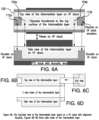
- Figures 6A-6D illustrate a pair fiducials 154a, 154b that are marked on a top surface of the intermediate layer 150.
- the fiducials 154a, 154b are measured with respect the fiducials 112a, 112b that are marked on the epoxy in the support frame.
- the fiducials 154a, 154b are marked on the intermediate layer once the intermediate layer is secured to the support frame behind the high frequency transducer.
- the fiducials 112a, 112b, 154a, 154b are crosses made with a laser.
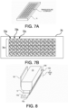
- FIG. 7A shows an embodiment of a piezoelectric layer 70 for the low frequency transducer.
- the piezoelectric layer 70 also includes an alumina frame surrounding a sheet of PZT or other piezoelectric material.
- the sheet of PZT is diced into a number of columns of triangular pillars as a 1-3 composite as best shown in Figure 7B .
- each column 72a, 72b, 72c of triangular elements 74 is treated as a single transducer element.
- the low frequency transducer includes 32 columns of triangular elements.
- the low frequency transducer could include fewer or a greater number of columns as desired.
- each transducer element in the low frequency transducer may have other shapes such a small squares or rectangular-shaped elements.
- FIG 8 is an isometric view of a low frequency transducer in accordance with an embodiment of the disclosed technology.
- the low frequency transducer includes the piezoelectric layer 70, one or more matching layers 160 positioned ahead of (e.g. in front of) the piezoelectric layer 70 and a backing layer 170 positioned behind the transducer elements.
- a flex circuit 180 includes signal traces that are electrically connected to individual low frequency transducer elements.
- the low frequency transducer also includes a pair of alignment tabs 162a, 162b.
- the alignment tabs are Kapton TM sheets inserted into an epoxy matching layer at a position away from the position of the low frequency transducer elements so as not to interfere with the operation of the low frequency transducer.
- Holes 164a, 164b are placed in the alignment tabs at a known distance from the low frequency transducer elements. The holes are placed over a fiducial on the high frequency transducer in order to precisely align the low frequency transducer elements with respect to the high frequency transducer elements.
- the holes 164a, 164b in the alignment tabs 162a, 162b are placed over the fiducials on the intermediate layer. If the alignment tabs are long enough, the holes in the alignment tabs could be placed over the fiducials marked on the support frame in order to align the low frequency transducer with respect to the high frequency transducer.
- FIG. 9A is a cross-sectional view of a low frequency transducer in accordance with one embodiment of the disclosed technology.
- the transducer includes the piezoelectric layer 70 and two matching layers 160 positioned in front of the piezoelectric layer.
- the matching layers match the impedance of the low frequency piezoelectric elements to the impedance of the intermediate layer to which the low frequency transducer is secured.
- a backing layer 170 is positioned behind the low frequency transducer elements.
- the alignment tabs 162a, 162b are part of a matching layer ahead of the low frequency transducer elements.
- the holes 164a, 164b in the alignment tabs are positioned at a known distance from the low transducer elements as can be seen in Figure 9B .
- a flex circuit 180 extends out from under the backing layer where connections are made to the transducer elements.
- Figures 10A and 10B show one way of connecting the signal and ground traces of a flex circuit to the corresponding electrodes in the low frequency array.
- the flex circuit 180 includes a number of signal traces 182 and a ground trace 184.
- the ground trace 184 is electrically connected to the ground electrode on the front of the low frequency array with a conductive epoxy 186 joined to conductive epoxy 188 in the notches 80 in the frame 70 or to vias in the frame.
- the exposed ends of the signal traces 182 can be adhesively secured to the transducer elements with a conductive epoxy. Because the transducer elements of the low frequency transducer are relatively large, they can be easily aligned signal traces 182 in the flex circuit 180.
- FIG 11 is a cross sectional view of the dual frequency transducer in accordance with one embodiment of the disclosed technology.
- the low frequency transducer elements 71 are directly aligned with the high frequency transducer elements 51 by placing the holes on the alignment tabs 162a, 162b over the fiducials on the intermediate layer.
- the holes in the alignment tabs are placed at a known location with respect to the low frequency transducer elements and the fiducials are precisely placed at a known location with respect to the high frequency transducer elements. Therefore, placing the holes over the fiducials on the intermediate layer precisely positions the low frequency transducer elements with respect to the high frequency transducer elements without having to align the transducer on a wet bench.
- FIG 12 shows one embodiment of a transducer housing 200 surrounding the dual frequency transducer array.
- the housing includes separate cables 202, 204 connecting the low and high frequency transducers.
- the low frequency transducer can be used alone to image tissue with low frequency ultrasound (e.g. in a frequency range of 4-10 MHz).
- the high frequency transducer can be used to image tissue with high frequency ultrasound (e.g. in a frequency range of 20-50 MHz).
- both transducers can be used to perform imaging such as harmonic or contrast agent imaging where a region of interest is insonified with signals from the low frequency transducer and ultrasound echo signals at harmonics of the excitation frequency are detected with the high frequency transducer.
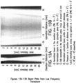
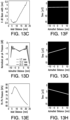
- Figures 13A-13H are some sample beam plots of a low frequency transducer operating in a plane wave imaging mode.
- a 32-element low frequency transducer is positioned behind a 256 element high frequency transducer.
- Electrical matching using 1:3 mini-transformers bring the impedance of the low frequency transducer elements from about 500 ohms to about 47.2 +1- 2.6 ohms with a phase of minus 60.1 +1- 5.5 degrees.
- the single low frequency element peak-peak pressures measured at 1.7 mm. from the lens were increased from 0.77 kPaN without matching to 1.51 kPa/V with matching in the 6-140V range with a variation of about +5°.1.0 across the elements.
Landscapes
- Engineering & Computer Science (AREA)
- Physics & Mathematics (AREA)
- Radar, Positioning & Navigation (AREA)
- Remote Sensing (AREA)
- Acoustics & Sound (AREA)
- Computer Networks & Wireless Communication (AREA)
- General Physics & Mathematics (AREA)
- Mechanical Engineering (AREA)
- Transducers For Ultrasonic Waves (AREA)
- Ultra Sonic Daignosis Equipment (AREA)
Description
- The disclosed technology relates to ultrasound transducers and in particular to dual frequency ultrasound transducers.
- In conventional ultrasound imaging, ultrasonic acoustic signals are directed towards a region of interest and the corresponding reflected echo signals are detected. Characteristics of the echo signals such as their amplitude, phase shift, Doppler shift, power etc. are analyzed and quantified into pixel data that are used to create an image of or representation of flow. With conventional single transducer ultrasound imaging, the received ultrasound echo signals are in the same frequency range as the transmitted ultrasound signals.
- Another approach to performing ultrasound imaging is to apply ultrasonic acoustic signals to the region of interest at one frequency and to capture and analyze the received echo signals at another frequency such as at one or more harmonics of the transmitted ultrasound signals. Typically, the harmonics have a frequency that is 3-5 times that of the transmitted signals. One specific use of harmonic imaging is imaging tissue with contrast agents. Contrast agents are generally fluid or lipid encapsulated microbubbles that are sized to resonate at a particular transmitted ultrasound frequency. Exposure to ultrasound in the body at the resonant frequency of the microbubbles, causes the bubbles to rupture and produce non-linear ultrasound echoes having a much higher frequency than the applied ultrasound. For example, non-linear microbubbles can be designed to resonate at 1-6 MHz but produce echo signals in the range of 10-30 MHz. The high frequency echo signals allow detailed images of tissue structures to be produced and studied such as the micro-vasculature surrounding tumors in clinical or pre-clinical settings.
- The most conventional way of performing dual frequency imaging is with a mechanically scanned, single element transducer having confocal low and high frequency transducer elements. While such transducers work well, faster scanning can be performed with transducer arrays that can be electronically steered. Such transducers generally have a low frequency transducer array and a high frequency transducer array that are aligned with each other. One problem with dual frequency transducers is aligning the low and high frequency arrays. In a 30 MHz high frequency phased array, the element size (e.g. 1/2 A or less) is about 25 microns. At 50 MHz, the element size is approximately 15 microns. For comparison, a typical human hair is approximately 80 microns in diameter. The procedure required to align the arrays often requires making micro-adjustments to the position of the high and low frequency transducers on a wet bench and then adhering them together when the best match is found. This is both time consuming and costly. The technology discussed herein relates to an improved dual frequency transducer that is easier and/or less costly to manufacture.
-
US 2017/282215 teaches a dual frequency ultrasound transducer having a low frequency ultrasound array positioned behind a high frequency ultrasound array, and a dampening material for attenuating high frequency signals positioned between the high frequency and low frequency arrays. -
US 8674524 teaches a semiconductor device having alignment markings on a layer of the device for use in aligning the layer with other layers of the device. -
US 2013/207519 discloses an ultrasound transducer that includes alignment markers on a bottom surface of a piezoelectric layer for use in correctly orienting the piezoelectric layer with respect to a flex circuit. - According to a first aspect, the invention provides a dual frequency transducer comprising: a high frequency (HF) transducer comprising a sheet of PZT material including a number of HF transducer elements, one or more matching layers, a lens positioned in front of the HF transducer elements and a support frame on a back side of the PZT material that supports one or more flex circuits with signal traces that connect to the HF transducer elements; an intermediate layer that is configured to absorb HF ultrasound signals and positioned behind the HF transducer elements; and a low frequency (LF) transducer; characterised in that the dual frequency transducer comprises one or more fiducials placed at known positions with respect to the HF transducer elements; and the LF transducer includes a sheet of PZT material including a number of LF transducer elements, one or more matching layers and a flex circuit with signal traces that connect to the LF transducer elements, wherein the LF transducer includes one or more alignment tabs with an alignment feature that aligns the LF transducer with one of the one or more fiducials.
- The support frame may include an alignment post that fits with a cooperating slot or keyway on the intermediate layer to align the intermediate layer with the support frame and the high frequency transducer elements. One or more fiducials on the intermediate layer may be positioned at locations referenced to the high frequency transducer elements to align the low frequency transducer to the high frequency transducer elements.
- According to a second embodiment, the invention provides a dual frequency transducer comprising: a high frequency (HF) transducer comprising a sheet of PZT material including a number of HF transducer elements; a backing material that is constructed to absorb HF ultrasound signals and pass low frequency (LF) ultrasound signals; and a low frequency (LF) transducer; characterised in that the dual frequency transducer comprises one or more fiducials placed at known positions with respect to the HF transducer elements; and the LF transducer includes a number of LF transducer elements including one or more alignment tabs that are positioned using the one or more fiducials to align the LF transducer elements with the HF transducer elements.
-
-
Figure 1A is a top view of a piezoelectric layer of a high frequency (HF) transducer; -
Figure 1B is a top view of a piezoelectric layer of a low frequency (LF) transducer; -
Figure 2 is a partial isometric view of a conductive frame and piezoelectric layer of a high frequency transducer array; -
Figure 3 is an isometric view of a piezoelectric layer, a flex circuit and a conductive frame with alignment features formed on a rear side of the frame; -
Figure 4 is an isometric view of an intermediate layer to be positioned between the low frequency transducer and the high frequency transducer; -
Figure 5 is a cross-sectional view of a dual frequency transducer with the intermediate layer in place over a high frequency transducer; -
Figures 6A-6D are top, side and end views of an intermediate layer aligned with a high frequency transducer; -
Figure 7A is an isometric view of piezoelectric layer of a low frequency transducer; -
Figure 7B shows an example of a low frequency transducer element dicing pattern; -
Figure 8 is an isometric view of a low frequency transducer; -
Figures 9A-9C are end, top and side views of a low frequency transducer; -
Figures 10A and 10B show how connections are made between ground and signal traces in a flex circuit to the electrodes for the low frequency transducer elements and common transducer ground electrode; -
Figure 11 is a cross-sectional view of a dual frequency transducer showing an alignment of high and low frequency transducer elements; -
Figure 12 shows a housing for a dual frequency transducer; and -
Figures 13A-13H show a number of beam plots from a low frequency transducer. - The technology shown in the figures and described below relates to a dual frequency ultrasound transducer. Components of a dual frequency transducer are shown for the purpose of explaining how to make and use the disclosed technology. It will be appreciated that the illustrations are not necessarily drawn to scale.
-
Figure 1 is a top view of apiezoelectric layer 50 for a high frequency ultrasound transducer in accordance with one embodiment of the disclosed technology. In one embodiment, thelayer 50 has anouter frame 52 that surrounds asheet 54 of PZT, single crystal piezoelectric or other known piezoelectric material. In one embodiment, theframe 52 is a pre-machined, non-conductive alumina ceramic with a center cut out area that is slightly larger than the outer dimensions of thesheet 54 of piezoelectric material. In other embodiments, theframe 52 can be made of a conductive material such as molybdenum or graphite. Theframe 52 preferably has a coefficient of thermal expansion that is similar to that of the piezoelectric material so that the piezoelectric material doesn't crack during manufacture, handling or use. An adhesive 56 such as EPO-TEK 301 epoxy fills a gap between the frame and the piezoelectric material. Thepiezoelectric material 54 is diced with a patterning laser or a dicing saw to create a number (e.g. 128, 256 or fewer or a larger number) of piezoelectric elements (not separately shown). By surrounding thesheet 54 of piezoelectric material with theframe 52, the kerf cuts that define the individual transducer elements can extend across the entire width of the sheet of piezoelectric material. - If the
frame 52 is made of a non-conductive material, a cut-out area ornotch 60 on one or both sides of the frame is filled with a conductive epoxy or can include a number of conductive vias to provide an electrical path from a front surface of the frame to a rear surface of the frame. More details about the construction of an ultrasound transducer with a surrounding frame can be found in commonly-ownedU.S. Patent Publication No. 2019/0200959 filed May 30, 2018 and International Publication No.2019/133271 . -
Figure 1B shows apiezoelectric layer 70 of a low frequency ultrasound transducer that in one embodiment, is constructed in the same manner as the piezoelectric layer of the high frequency transducer shown inFigure 1A . Analumina frame 72 surrounds asheet 74 of piezoelectric material. Theframe 72 has a central opening that is sized to form a gap between the edges of the opening and the edges of thepiezoelectric sheet 74. The gap is filled with anon-conductive epoxy 76. The low frequency array has fewer transducer elements than the high frequency transducer. In one embodiment, the low frequency transducer has 32 individually addressable transducer elements but could have fewer or more elements. A pair of cut-out areas ornotches 80 on either side of theframe 72 can be filled with a conductive epoxy or can include conductive vies through the frame to provide an electrical path from a front surface of the low frequency array to the rear surface of the frame. -
Figure 2 is an isometric view of aconductive support frame 100 that is to be secured to a rear surface of thepiezoelectric layer 50 of the high frequency transducer. Theframe 100 supports one or more flex circuits (not shown) having signal traces therein that are electrically connected to corresponding electrodes on each of the high frequency transducer elements. In addition, thesupport frame 100 provides electromagnetic shielding for the rear surface of the transducer elements. A common ground electrode on the front surface of thepiezoelectric layer 50 is connected to a ground plane in the flex circuits via a conductive path that includes theconductive support frame 100. In one embodiment, thesupport frame 100 is secured to thepiezoelectric layer 50 with a conductive epoxy. Also shown inFigure 2 are one or more matching layers and a lens that are positioned ahead of (e.g. in front of) thepiezoelectric layer 50. -
Figure 3 shows oneflex circuit 104 attached to thesupport frame 100. In some embodiments, the high frequency transducer includes two flex circuits with the signal traces of one flex circuit electrically coupled to the even numbered transducer elements and the signal traces of the other flex circuit electrically connected to the odd numbered transducer elements. Electrical connections are made from the individual transducer elements on the rear surface of the piezoelectric layer to the metal signal traces in the flex circuits. Connections between the transducer elements and the metal
signal traces in the flex circuits can be made using the techniques described inU.S. Patent Publication No. 2017/0144192 orU.S. Patent No. 8,316,518 . After the connections are made, an open back side of the support frame is filled with anepoxy material 110 such as EPO-TEK 301. In one embodiment, the height of the epoxy 110 in the frame extends above the rim of thesupport frame 100. As shown inFigure 3 , the epoxy 110 is molded or laser machined to form a pair ofalignment posts recess area 114 that is behind the high frequency transducer elements. In one embodiment, the depth of therecess area 114 is about 4.2 mm. The alignment posts 112a, 112b are configured to align an intermediate layer over the high frequency transducer as will be described below. A pair of fiducials 120a, 120b are marked with a laser on each alignment post at a known distance from the high frequency transducer elements. Thefiducials -
Figure 4 illustrates one embodiment of anintermediate layer 150 that is placed behind the high frequency transducer. In one embodiment, theintermediate layer 150 is made of silicone powder-doped EPO-TEK 301 epoxy. The size of the silicone powder is in the nanometer range such that it highly attenuates high frequency (HF) ultrasound and passes low frequency (LF) ultrasound. The intermediate layer is sized to absorb high frequency ultrasound to a specified level, such as 65 dB, but to pass low frequency signals transmitted from, or to be received by, the low frequency transducer. The top of theintermediate layer 150 includes a pair of slots orkeyways alignment posts frame 100 to align theintermediate layer 150 at a known position with respect to transducer elements of the high frequency transducer. In one embodiment, theintermediate layer 150 is secured to theframe 100 using the same epoxy that fills the back side of the frame to avoid acoustic discontinuities at the bond line. - Once the intermediate layer is secured to the
frame 100,additional fiducials -
Figure 5 shows a cross section of the high frequency transducer with theintermediate layer 150 secured to the back of thesupport frame 100. As shown, the high frequency transducer comprises alens 130 designed to focus the high frequency ultrasound signals at a specific depth. Typical lens materials include polymethylpentene (tradename TPX), cross-linked polystyrene (tradename Rexolite) or polybenzimidazone (tradename Celezole). However, other non-attenuating plastic materials could also be used. Behind the lens are one or more quarterwave matching layers 132 that match the impedance of thepiezoelectric layer 50 to the impedance of thelens 130. The one or more matching layers are generally formed by adding particles to an epoxy to adjust its acoustic impedance. A metallic (e.g. gold or gold+chromium) common ground electrode is deposited on the front surface of thepiezoelectric layer 50 is electrically coupled to theconductive support frame 100 through the slots or vias in theframe 52 surrounding the PZT material. An applied metal coating on the rear or proximal surface of the piezoelectric layer is formed into conductive paths from individual transducer elements to the signal traces in the flex circuit. The layer ofepoxy 110 covers the proximal side of the transducer elements and fills in the rear side of the support frame. In one embodiment, therecess 114 formed in the epoxy behind the high frequency transducer array is sized such that the intermediate layer is larger in the elevation and azimuthal dimensions of the transducer than the size of the transducer elements so that the intermediate layer extends over the ends of high frequency transducer elements. -
Figures 6A-6D illustrate apair fiducials intermediate layer 150. Thefiducials fiducials -
Figure 7A shows an embodiment of apiezoelectric layer 70 for the low frequency transducer. In the embodiment shown, thepiezoelectric layer 70 also includes an alumina frame surrounding a sheet of PZT or other piezoelectric material. In one embodiment, the sheet of PZT is diced into a number of columns of triangular pillars as a 1-3 composite as best shown inFigure 7B . In the example shown, eachcolumn triangular elements 74 is treated as a single transducer element. InFigure 7B , only 12 columns of transducer elements are shown for purposes of illustration. In one embodiment, the low frequency transducer includes 32 columns of triangular elements. However, the low frequency transducer could include fewer or a greater number of columns as desired. Furthermore, each transducer element in the low frequency transducer may have other shapes such a small squares or rectangular-shaped elements. -
Figure 8 is an isometric view of a low frequency transducer in accordance with an embodiment of the disclosed technology. The low frequency transducer includes thepiezoelectric layer 70, one or more matching layers 160 positioned ahead of (e.g. in front of) thepiezoelectric layer 70 and abacking layer 170 positioned behind the transducer elements. Aflex circuit 180 includes signal traces that are electrically connected to individual low frequency transducer elements. The low frequency transducer also includes a pair ofalignment tabs Holes 164a, 164b are placed in the alignment tabs at a known distance from the low frequency transducer elements. The holes are placed over a fiducial on the high frequency transducer in order to precisely align the low frequency transducer elements with respect to the high frequency transducer elements. - In one embodiment, the
holes 164a, 164b in thealignment tabs -
Figures 9A is a cross-sectional view of a low frequency transducer in accordance with one embodiment of the disclosed technology. The transducer includes thepiezoelectric layer 70 and twomatching layers 160 positioned in front of the piezoelectric layer. The matching layers match the impedance of the low frequency piezoelectric elements to the impedance of the intermediate layer to which the low frequency transducer is secured. Abacking layer 170 is positioned behind the low frequency transducer elements. As shown inFigure 9C , thealignment tabs holes 164a, 164b in the alignment tabs are positioned at a known distance from the low transducer elements as can be seen inFigure 9B . Aflex circuit 180 extends out from under the backing layer where connections are made to the transducer elements. -
Figures 10A and 10B show one way of connecting the signal and ground traces of a flex circuit to the corresponding electrodes in the low frequency array. As shown inFigure 10A , theflex circuit 180 includes a number of signal traces 182 and aground trace 184. Theground trace 184 is electrically connected to the ground electrode on the front of the low frequency array with aconductive epoxy 186 joined toconductive epoxy 188 in thenotches 80 in theframe 70 or to vias in the frame. As shown inFigure 10B , the exposed ends of the signal traces 182 can be adhesively secured to the transducer elements with a conductive epoxy. Because the transducer elements of the low frequency transducer are relatively large, they can be easily aligned signal traces 182 in theflex circuit 180. -
Figure 11 is a cross sectional view of the dual frequency transducer in accordance with one embodiment of the disclosed technology. The low frequency transducer elements 71 are directly aligned with the high frequency transducer elements 51 by placing the holes on thealignment tabs -
Figure 12 shows one embodiment of atransducer housing 200 surrounding the dual frequency transducer array. In the embodiment shown the housing includesseparate cables -
Figures 13A-13H are some sample beam plots of a low frequency transducer operating in a plane wave imaging mode. In one embodiment, a 32-element low frequency transducer is positioned behind a 256 element high frequency transducer. Electrical matching using 1:3 mini-transformers bring the impedance of the low frequency transducer elements from about 500 ohms to about 47.2 +1- 2.6 ohms with a phase of minus 60.1 +1- 5.5 degrees. The single low frequency element peak-peak pressures measured at 1.7 mm. from the lens were increased from 0.77 kPaN without matching to 1.51 kPa/V with matching in the 6-140V range with a variation of about +5°.1.0 across the elements. In plane wave imaging, pressure is 3 times higher than for a single element. Focusing is observed in the elevation plane at 5.5 mm with a 6dB beamwidth of 2.7 mm (Figs 13A ,13C ). Past the focus, the pressure drops as the wavefront diverges (Fig. 13E ). In the azimuth direction, the beam is relatively uniform (without apodization), with a variation of 2dB relative to the maximum on the edges (Figs 13B ,13D ). Beam steering is achieved for +1- 18 degree angles (Figs 13F-13H ) allowing for planewave compounding. - From the foregoing, it will be appreciated that specific embodiments of the invention have been described herein for purposes of illustration, but that various modifications may be made without deviating from the scope of the invention. Accordingly, the invention is not limited except as by the appended claims.
Claims (14)
- A dual frequency transducer comprising:a high frequency transducer comprising a sheet of PZT material (54) including a number of high frequency transducer elements, one or more matching layers (132), a lens (130) positioned in front of the high frequency transducer elements and a support frame (100) on a back side of the PZT material (54) that supports one or more flex circuits (104) with signal traces that connect to the high frequency transducer elements;an intermediate layer (150) that is configured to absorb high frequency ultrasound signals and positioned behind the high frequency transducer elements; anda low frequency transducer;characterised in that the dual frequency transducer comprises one or more fiducials (120a, 120b) placed at known positions with respect to the high frequency transducer elements; andthe low frequency transducer includes a sheet of PZT material including a number of low frequency transducer elements, one or more matching layers (160) and a flex circuit (180) with signal traces that connect to the low frequency transducer elements, wherein the low frequency transducer includes one or more alignment tabs (162a, 162b) with an alignment feature that aligns the low frequency transducer with one of the one or more fiducials (120a, 120b).
- The dual frequency transducer of claim 1, wherein the alignment feature comprises a hole (164a, 164b) on an alignment tab (162a, 162b) that is at a known position with respect to the low frequency transducer elements of the low frequency transducer.
- The dual frequency transducer of claim 2, wherein the alignment feature comprises an alignment tab extending from a matching layer (160) in the low frequency transducer.
- The dual frequency transducer of claim 3, wherein the alignment tab includes a hole (164a, 164b) to place over a fiducial (120a, 120b) on the high frequency transducer.
- The dual frequency transducer of claim 1, wherein the intermediate layer (150) is made of silicone powder-doped epoxy.
- The dual frequency transducer of claim 5, wherein a rear surface of the support frame (100) is filled with an epoxy (110) having a recess (114) into which a portion of the intermediate layer (150) is fitted.
- The dual frequency transducer of claim 6, wherein the intermediate layer (150) is adhered to the recess (114) with the same epoxy in which the recess (114) is formed.
- The dual frequency transducer of claim 5, further comprising:a pair of alignment pillars (112a, 112b) on a back side of the support frame (100); andone or more keyways (152a, 152b) in the intermediate layer (150) that cooperate with the alignment pillars (112a, 112b) so that the intermediate layer (150) is aligned with respect to the high frequency transducer elements.
- The dual frequency transducer of claim 1, wherein the intermediate layer (150) is larger than an area of the high frequency transducer elements in the piezoelectric layer of the high frequency transducer.
- The dual frequency transducer array of claim 1, wherein the intermediate layer (150) includes at least one fiducial (154a, 154b) placed at a known position with respect to the location of the high frequency transducer elements, and wherein the alignment feature on the low frequency transducer is aligned with the at least one fiducial (154a, 154b) on the intermediate layer (150).
- A dual frequency transducer comprising:a high frequency transducer comprising a sheet of PZT material (54) including a number of high frequency transducer elements;a backing material (170) that is constructed to absorb high frequency ultrasound signals and pass low frequency ultrasound signals;
anda low frequency transducer;characterised in that the dual frequency transducer comprises one or more fiducials (120a, 120b) placed at known positions with respect to the high frequency transducer elements; andthe low frequency transducer includes a number of low frequency transducer elements including one or more alignment tabs (162a, 162b) that are positioned using the one or more fiducials (120a, 120b) to align the low frequency transducer elements with the high frequency transducer elements. - The dual frequency transducer of claim 11, wherein the one or more alignment tabs (162a, 162b) in the low frequency transducer are incorporated into a matching layer (160) of the low frequency transducer.
- The dual frequency transducer of claim 12, wherein the one or more alignment tabs (162a, 162b) are secured in an epoxy layer that forms the matching layer (160).
- The dual frequency transducer of claim 13, wherein the one or more alignment tabs (162a, 162b) include a hole (164a, 164b) that is placed over a fiducial (120a, 120b) to align the low frequency transducer elements with respect to the high frequency transducer elements.
Applications Claiming Priority (3)
| Application Number | Priority Date | Filing Date | Title |
|---|---|---|---|
| US201862666519P | 2018-05-03 | 2018-05-03 | |
| US16/051,060 US11169265B2 (en) | 2018-05-03 | 2018-07-31 | Dual frequency ultrasound transducer |
| PCT/US2019/028832 WO2019212813A1 (en) | 2018-05-03 | 2019-04-24 | Dual frequency ultrasound transducer |
Publications (3)
| Publication Number | Publication Date |
|---|---|
| EP3788361A1 EP3788361A1 (en) | 2021-03-10 |
| EP3788361A4 EP3788361A4 (en) | 2022-01-19 |
| EP3788361B1 true EP3788361B1 (en) | 2025-01-29 |
Family
ID=68385113
Family Applications (1)
| Application Number | Title | Priority Date | Filing Date |
|---|---|---|---|
| EP19796200.4A Active EP3788361B1 (en) | 2018-05-03 | 2019-04-24 | Dual frequency ultrasound transducer |
Country Status (4)
| Country | Link |
|---|---|
| US (2) | US11169265B2 (en) |
| EP (1) | EP3788361B1 (en) |
| JP (2) | JP7362659B2 (en) |
| WO (1) | WO2019212813A1 (en) |
Families Citing this family (10)
| Publication number | Priority date | Publication date | Assignee | Title |
|---|---|---|---|---|
| TWI743411B (en) * | 2017-11-08 | 2021-10-21 | 美商富士膠片索諾聲公司 | Ultrasound system with high frequency detail |
| US11169265B2 (en) * | 2018-05-03 | 2021-11-09 | Fujifilm Sonosite, Inc. | Dual frequency ultrasound transducer |
| CN112740026A (en) * | 2018-09-21 | 2021-04-30 | 蝴蝶网络有限公司 | Acoustic damping for ultrasound imaging devices |
| WO2020167992A1 (en) | 2019-02-13 | 2020-08-20 | Craniovation, Inc. | Non-invasive sonodynamic therapy |
| CA3185803A1 (en) | 2020-08-07 | 2022-02-10 | Vijay Agarwal | Ultrasound arrays for enhanced sonodynamic therapy for treating cancer |
| CN112433008A (en) * | 2020-10-28 | 2021-03-02 | 上海船舶工程质量检测有限公司 | Double-frequency phased array ultrasonic probe for industrial detection |
| CN114190976B (en) * | 2021-11-15 | 2023-07-21 | 北京航空航天大学 | A dual-frequency ultrasonic transducer array and its working method |
| US12558708B2 (en) | 2021-12-23 | 2026-02-24 | Fujifilm Sonosite, Inc. | Array architecture and interconnection for transducers |
| CN115356402B (en) * | 2022-07-12 | 2025-03-25 | 重庆大学 | Integrated dual-frequency ultrasonic transducer, working method and application |
| CN119114409B (en) * | 2024-09-20 | 2025-09-05 | 吉林大学 | A stretchable dual-frequency flexible ultrasonic transducer |
Family Cites Families (14)
| Publication number | Priority date | Publication date | Assignee | Title |
|---|---|---|---|---|
| JP2004363746A (en) | 2003-06-03 | 2004-12-24 | Fuji Photo Film Co Ltd | Ultrasonic probe and its manufacturing method |
| US20050108877A1 (en) * | 2003-11-24 | 2005-05-26 | Peterson Eric C. | Apparatus and method for coupling a thermal dissipation device to an electronic substrate |
| EP1699360A4 (en) | 2003-12-30 | 2009-05-06 | Liposonix Inc | Component ultrasound transducer |
| US8316518B2 (en) | 2008-09-18 | 2012-11-27 | Visualsonics Inc. | Methods for manufacturing ultrasound transducers and other components |
| US9173047B2 (en) | 2008-09-18 | 2015-10-27 | Fujifilm Sonosite, Inc. | Methods for manufacturing ultrasound transducers and other components |
| JP2010087965A (en) | 2008-10-01 | 2010-04-15 | Konica Minolta Medical & Graphic Inc | Method of manufacturing array type ultrasonic vibrator |
| US8531089B2 (en) | 2008-10-17 | 2013-09-10 | Konica Minolta Medical & Graphic, Inc. | Array-type ultrasonic vibrator |
| ES2458629T3 (en) | 2009-06-19 | 2014-05-06 | Sonovia Holdings Llc | Dual Frequency Ultrasound Transducer |
| US8674524B1 (en) | 2012-10-12 | 2014-03-18 | Infineon Technologies Ag | Alignment marks and a semiconductor workpiece |
| CA3004354C (en) | 2015-11-25 | 2024-01-09 | Fujifilm Sonosite, Inc. | High frequency ultrasound transducer and method for manufacture |
| US10661309B2 (en) | 2016-04-01 | 2020-05-26 | Fujifilm Sonosite, Inc. | Dual frequency ultrasound transducer including an ultrahigh frequency transducer stack and a low frequency ultrasound transducer stack |
| EP3479721B1 (en) | 2017-11-07 | 2020-05-13 | The Swatch Group Research and Development Ltd | Method for crimping a stone |
| US11678865B2 (en) | 2017-12-29 | 2023-06-20 | Fujifilm Sonosite, Inc. | High frequency ultrasound transducer |
| US11169265B2 (en) * | 2018-05-03 | 2021-11-09 | Fujifilm Sonosite, Inc. | Dual frequency ultrasound transducer |
-
2018
- 2018-07-31 US US16/051,060 patent/US11169265B2/en not_active Expired - Fee Related
-
2019
- 2019-04-24 EP EP19796200.4A patent/EP3788361B1/en active Active
- 2019-04-24 WO PCT/US2019/028832 patent/WO2019212813A1/en not_active Ceased
- 2019-04-24 JP JP2020561888A patent/JP7362659B2/en active Active
-
2021
- 2021-11-09 US US17/522,293 patent/US11774589B2/en active Active
-
2023
- 2023-10-04 JP JP2023173264A patent/JP7666793B2/en active Active
Also Published As
| Publication number | Publication date |
|---|---|
| US11774589B2 (en) | 2023-10-03 |
| EP3788361A4 (en) | 2022-01-19 |
| JP2023179625A (en) | 2023-12-19 |
| US20220066027A1 (en) | 2022-03-03 |
| WO2019212813A1 (en) | 2019-11-07 |
| JP2021526324A (en) | 2021-09-30 |
| JP7666793B2 (en) | 2025-04-22 |
| JP7362659B2 (en) | 2023-10-17 |
| EP3788361A1 (en) | 2021-03-10 |
| US20190339387A1 (en) | 2019-11-07 |
| US11169265B2 (en) | 2021-11-09 |
Similar Documents
| Publication | Publication Date | Title |
|---|---|---|
| US11774589B2 (en) | Dual frequency ultrasound transducer | |
| JP3478874B2 (en) | Ultrasonic phased array converter and method of manufacturing the same | |
| US5651365A (en) | Phased array transducer design and method for manufacture thereof | |
| US8182428B2 (en) | Dual frequency band ultrasound transducer arrays | |
| US6656124B2 (en) | Stack based multidimensional ultrasonic transducer array | |
| EP2243561B1 (en) | Array of electroacoustic transducers and electronic probe for three-dimensional images comprising said transducer array | |
| US7727156B2 (en) | Dual frequency band ultrasound transducer arrays | |
| CN101965232B (en) | Multiple frequency band acoustic transducer arrays | |
| US5706820A (en) | Ultrasonic transducer with reduced elevation sidelobes and method for the manufacture thereof | |
| US5743855A (en) | Broadband phased array transducer design with frequency controlled two dimension capability and methods for manufacture thereof | |
| US11678865B2 (en) | High frequency ultrasound transducer | |
| JP3824315B2 (en) | Multidimensional arrays and their manufacture | |
| US11541423B2 (en) | Ultrasound transducer with curved transducer stack | |
| EP1728563B1 (en) | Ultrasonic probe and ultrasonic probe manufacturing method | |
| WO2023019554A1 (en) | Multi-frequency ultrasonic transducer, ultrasonic imaging system having same, and ultrasonic imaging method | |
| CN113643677B (en) | A multi-frequency ultrasonic transducer and an ultrasonic imaging system and method having the same | |
| CN216212320U (en) | Multi-frequency ultrasonic transducer and ultrasonic imaging system with same |
Legal Events
| Date | Code | Title | Description |
|---|---|---|---|
| STAA | Information on the status of an ep patent application or granted ep patent |
Free format text: STATUS: THE INTERNATIONAL PUBLICATION HAS BEEN MADE |
|
| PUAI | Public reference made under article 153(3) epc to a published international application that has entered the european phase |
Free format text: ORIGINAL CODE: 0009012 |
|
| STAA | Information on the status of an ep patent application or granted ep patent |
Free format text: STATUS: REQUEST FOR EXAMINATION WAS MADE |
|
| 17P | Request for examination filed |
Effective date: 20201123 |
|
| AK | Designated contracting states |
Kind code of ref document: A1 Designated state(s): AL AT BE BG CH CY CZ DE DK EE ES FI FR GB GR HR HU IE IS IT LI LT LU LV MC MK MT NL NO PL PT RO RS SE SI SK SM TR |
|
| AX | Request for extension of the european patent |
Extension state: BA ME |
|
| DAV | Request for validation of the european patent (deleted) | ||
| DAX | Request for extension of the european patent (deleted) | ||
| A4 | Supplementary search report drawn up and despatched |
Effective date: 20211217 |
|
| RIC1 | Information provided on ipc code assigned before grant |
Ipc: B06B 1/06 20060101ALI20211213BHEP Ipc: G01N 29/24 20060101ALI20211213BHEP Ipc: G01N 29/22 20060101ALI20211213BHEP Ipc: G01S 7/52 20060101ALI20211213BHEP Ipc: G01S 15/89 20060101AFI20211213BHEP |
|
| REG | Reference to a national code |
Ref country code: DE Ref legal event code: R079 Free format text: PREVIOUS MAIN CLASS: G01N0029220000 Ipc: G01S0015890000 Ref document number: 602019065431 Country of ref document: DE |
|
| GRAP | Despatch of communication of intention to grant a patent |
Free format text: ORIGINAL CODE: EPIDOSNIGR1 |
|
| STAA | Information on the status of an ep patent application or granted ep patent |
Free format text: STATUS: GRANT OF PATENT IS INTENDED |
|
| RIC1 | Information provided on ipc code assigned before grant |
Ipc: B06B 1/06 20060101ALI20240923BHEP Ipc: G01N 29/24 20060101ALI20240923BHEP Ipc: G01N 29/22 20060101ALI20240923BHEP Ipc: G01S 7/52 20060101ALI20240923BHEP Ipc: G01S 15/89 20060101AFI20240923BHEP |
|
| INTG | Intention to grant announced |
Effective date: 20241004 |
|
| GRAS | Grant fee paid |
Free format text: ORIGINAL CODE: EPIDOSNIGR3 |
|
| GRAA | (expected) grant |
Free format text: ORIGINAL CODE: 0009210 |
|
| STAA | Information on the status of an ep patent application or granted ep patent |
Free format text: STATUS: THE PATENT HAS BEEN GRANTED |
|
| AK | Designated contracting states |
Kind code of ref document: B1 Designated state(s): AL AT BE BG CH CY CZ DE DK EE ES FI FR GB GR HR HU IE IS IT LI LT LU LV MC MK MT NL NO PL PT RO RS SE SI SK SM TR |
|
| REG | Reference to a national code |
Ref country code: GB Ref legal event code: FG4D |
|
| REG | Reference to a national code |
Ref country code: CH Ref legal event code: EP |
|
| REG | Reference to a national code |
Ref country code: DE Ref legal event code: R096 Ref document number: 602019065431 Country of ref document: DE |
|
| REG | Reference to a national code |
Ref country code: IE Ref legal event code: FG4D |
|
| REG | Reference to a national code |
Ref country code: NL Ref legal event code: FP |
|
| PG25 | Lapsed in a contracting state [announced via postgrant information from national office to epo] |
Ref country code: RS Free format text: LAPSE BECAUSE OF FAILURE TO SUBMIT A TRANSLATION OF THE DESCRIPTION OR TO PAY THE FEE WITHIN THE PRESCRIBED TIME-LIMIT Effective date: 20250429 |
|
| PG25 | Lapsed in a contracting state [announced via postgrant information from national office to epo] |
Ref country code: FI Free format text: LAPSE BECAUSE OF FAILURE TO SUBMIT A TRANSLATION OF THE DESCRIPTION OR TO PAY THE FEE WITHIN THE PRESCRIBED TIME-LIMIT Effective date: 20250129 |
|
| PG25 | Lapsed in a contracting state [announced via postgrant information from national office to epo] |
Ref country code: PL Free format text: LAPSE BECAUSE OF FAILURE TO SUBMIT A TRANSLATION OF THE DESCRIPTION OR TO PAY THE FEE WITHIN THE PRESCRIBED TIME-LIMIT Effective date: 20250129 |
|
| PGFP | Annual fee paid to national office [announced via postgrant information from national office to epo] |
Ref country code: DE Payment date: 20250402 Year of fee payment: 7 |
|
| PG25 | Lapsed in a contracting state [announced via postgrant information from national office to epo] |
Ref country code: ES Free format text: LAPSE BECAUSE OF FAILURE TO SUBMIT A TRANSLATION OF THE DESCRIPTION OR TO PAY THE FEE WITHIN THE PRESCRIBED TIME-LIMIT Effective date: 20250129 |
|
| REG | Reference to a national code |
Ref country code: LT Ref legal event code: MG9D |
|
| PG25 | Lapsed in a contracting state [announced via postgrant information from national office to epo] |
Ref country code: NO Free format text: LAPSE BECAUSE OF FAILURE TO SUBMIT A TRANSLATION OF THE DESCRIPTION OR TO PAY THE FEE WITHIN THE PRESCRIBED TIME-LIMIT Effective date: 20250429 Ref country code: IS Free format text: LAPSE BECAUSE OF FAILURE TO SUBMIT A TRANSLATION OF THE DESCRIPTION OR TO PAY THE FEE WITHIN THE PRESCRIBED TIME-LIMIT Effective date: 20250529 |
|
| REG | Reference to a national code |
Ref country code: AT Ref legal event code: MK05 Ref document number: 1763980 Country of ref document: AT Kind code of ref document: T Effective date: 20250129 |
|
| PG25 | Lapsed in a contracting state [announced via postgrant information from national office to epo] |
Ref country code: HR Free format text: LAPSE BECAUSE OF FAILURE TO SUBMIT A TRANSLATION OF THE DESCRIPTION OR TO PAY THE FEE WITHIN THE PRESCRIBED TIME-LIMIT Effective date: 20250129 |
|
| PG25 | Lapsed in a contracting state [announced via postgrant information from national office to epo] |
Ref country code: LV Free format text: LAPSE BECAUSE OF FAILURE TO SUBMIT A TRANSLATION OF THE DESCRIPTION OR TO PAY THE FEE WITHIN THE PRESCRIBED TIME-LIMIT Effective date: 20250129 Ref country code: PT Free format text: LAPSE BECAUSE OF FAILURE TO SUBMIT A TRANSLATION OF THE DESCRIPTION OR TO PAY THE FEE WITHIN THE PRESCRIBED TIME-LIMIT Effective date: 20250529 |
|
| PG25 | Lapsed in a contracting state [announced via postgrant information from national office to epo] |
Ref country code: BG Free format text: LAPSE BECAUSE OF FAILURE TO SUBMIT A TRANSLATION OF THE DESCRIPTION OR TO PAY THE FEE WITHIN THE PRESCRIBED TIME-LIMIT Effective date: 20250129 Ref country code: GR Free format text: LAPSE BECAUSE OF FAILURE TO SUBMIT A TRANSLATION OF THE DESCRIPTION OR TO PAY THE FEE WITHIN THE PRESCRIBED TIME-LIMIT Effective date: 20250430 |
|
| PG25 | Lapsed in a contracting state [announced via postgrant information from national office to epo] |
Ref country code: AT Free format text: LAPSE BECAUSE OF FAILURE TO SUBMIT A TRANSLATION OF THE DESCRIPTION OR TO PAY THE FEE WITHIN THE PRESCRIBED TIME-LIMIT Effective date: 20250129 |
|
| PG25 | Lapsed in a contracting state [announced via postgrant information from national office to epo] |
Ref country code: SE Free format text: LAPSE BECAUSE OF FAILURE TO SUBMIT A TRANSLATION OF THE DESCRIPTION OR TO PAY THE FEE WITHIN THE PRESCRIBED TIME-LIMIT Effective date: 20250129 |
|
| PG25 | Lapsed in a contracting state [announced via postgrant information from national office to epo] |
Ref country code: SM Free format text: LAPSE BECAUSE OF FAILURE TO SUBMIT A TRANSLATION OF THE DESCRIPTION OR TO PAY THE FEE WITHIN THE PRESCRIBED TIME-LIMIT Effective date: 20250129 |
|
| PG25 | Lapsed in a contracting state [announced via postgrant information from national office to epo] |
Ref country code: DK Free format text: LAPSE BECAUSE OF FAILURE TO SUBMIT A TRANSLATION OF THE DESCRIPTION OR TO PAY THE FEE WITHIN THE PRESCRIBED TIME-LIMIT Effective date: 20250129 |
|
| PG25 | Lapsed in a contracting state [announced via postgrant information from national office to epo] |
Ref country code: IT Free format text: LAPSE BECAUSE OF FAILURE TO SUBMIT A TRANSLATION OF THE DESCRIPTION OR TO PAY THE FEE WITHIN THE PRESCRIBED TIME-LIMIT Effective date: 20250129 |
|
| PG25 | Lapsed in a contracting state [announced via postgrant information from national office to epo] |
Ref country code: CZ Free format text: LAPSE BECAUSE OF FAILURE TO SUBMIT A TRANSLATION OF THE DESCRIPTION OR TO PAY THE FEE WITHIN THE PRESCRIBED TIME-LIMIT Effective date: 20250129 Ref country code: EE Free format text: LAPSE BECAUSE OF FAILURE TO SUBMIT A TRANSLATION OF THE DESCRIPTION OR TO PAY THE FEE WITHIN THE PRESCRIBED TIME-LIMIT Effective date: 20250129 |
|
| PG25 | Lapsed in a contracting state [announced via postgrant information from national office to epo] |
Ref country code: RO Free format text: LAPSE BECAUSE OF FAILURE TO SUBMIT A TRANSLATION OF THE DESCRIPTION OR TO PAY THE FEE WITHIN THE PRESCRIBED TIME-LIMIT Effective date: 20250129 |
|
| PG25 | Lapsed in a contracting state [announced via postgrant information from national office to epo] |
Ref country code: SK Free format text: LAPSE BECAUSE OF FAILURE TO SUBMIT A TRANSLATION OF THE DESCRIPTION OR TO PAY THE FEE WITHIN THE PRESCRIBED TIME-LIMIT Effective date: 20250129 |
|
| REG | Reference to a national code |
Ref country code: DE Ref legal event code: R097 Ref document number: 602019065431 Country of ref document: DE |
|
| REG | Reference to a national code |
Ref country code: CH Ref legal event code: H13 Free format text: ST27 STATUS EVENT CODE: U-0-0-H10-H13 (AS PROVIDED BY THE NATIONAL OFFICE) Effective date: 20251125 |
|
| PLBE | No opposition filed within time limit |
Free format text: ORIGINAL CODE: 0009261 |
|
| STAA | Information on the status of an ep patent application or granted ep patent |
Free format text: STATUS: NO OPPOSITION FILED WITHIN TIME LIMIT |
|
| PG25 | Lapsed in a contracting state [announced via postgrant information from national office to epo] |
Ref country code: LU Free format text: LAPSE BECAUSE OF NON-PAYMENT OF DUE FEES Effective date: 20250424 |
|
| PG25 | Lapsed in a contracting state [announced via postgrant information from national office to epo] |
Ref country code: MC Free format text: LAPSE BECAUSE OF FAILURE TO SUBMIT A TRANSLATION OF THE DESCRIPTION OR TO PAY THE FEE WITHIN THE PRESCRIBED TIME-LIMIT Effective date: 20250129 |
|
| REG | Reference to a national code |
Ref country code: BE Ref legal event code: MM Effective date: 20250430 |
|
| 26N | No opposition filed |
Effective date: 20251030 |
|
| PG25 | Lapsed in a contracting state [announced via postgrant information from national office to epo] |
Ref country code: BE Free format text: LAPSE BECAUSE OF NON-PAYMENT OF DUE FEES Effective date: 20250430 |
|
| PG25 | Lapsed in a contracting state [announced via postgrant information from national office to epo] |
Ref country code: CH Free format text: LAPSE BECAUSE OF NON-PAYMENT OF DUE FEES Effective date: 20250430 |
|
| PGFP | Annual fee paid to national office [announced via postgrant information from national office to epo] |
Ref country code: GB Payment date: 20260313 Year of fee payment: 8 |
|
| PG25 | Lapsed in a contracting state [announced via postgrant information from national office to epo] |
Ref country code: IE Free format text: LAPSE BECAUSE OF NON-PAYMENT OF DUE FEES Effective date: 20250424 |
|
| PGFP | Annual fee paid to national office [announced via postgrant information from national office to epo] |
Ref country code: NL Payment date: 20260317 Year of fee payment: 8 |
|
| PGFP | Annual fee paid to national office [announced via postgrant information from national office to epo] |
Ref country code: FR Payment date: 20260309 Year of fee payment: 8 |