EP3788231B1 - Erstellen von frakturen in einer formation mit elektromagnetischen signalen - Google Patents
Erstellen von frakturen in einer formation mit elektromagnetischen signalen Download PDFInfo
- Publication number
- EP3788231B1 EP3788231B1 EP18783133.4A EP18783133A EP3788231B1 EP 3788231 B1 EP3788231 B1 EP 3788231B1 EP 18783133 A EP18783133 A EP 18783133A EP 3788231 B1 EP3788231 B1 EP 3788231B1
- Authority
- EP
- European Patent Office
- Prior art keywords
- formation
- temperature
- signals
- wellbore
- enabler
- Prior art date
- Legal status (The legal status is an assumption and is not a legal conclusion. Google has not performed a legal analysis and makes no representation as to the accuracy of the status listed.)
- Active
Links
Images


Classifications
-
- E—FIXED CONSTRUCTIONS
- E21—EARTH OR ROCK DRILLING; MINING
- E21B—EARTH OR ROCK DRILLING; OBTAINING OIL, GAS, WATER, SOLUBLE OR MELTABLE MATERIALS OR A SLURRY OF MINERALS FROM WELLS
- E21B43/00—Methods or apparatus for obtaining oil, gas, water, soluble or meltable materials or a slurry of minerals from wells
- E21B43/25—Methods for stimulating production
- E21B43/26—Methods for stimulating production by forming crevices or fractures
- E21B43/2605—Methods for stimulating production by forming crevices or fractures using gas or liquefied gas
-
- E—FIXED CONSTRUCTIONS
- E21—EARTH OR ROCK DRILLING; MINING
- E21B—EARTH OR ROCK DRILLING; OBTAINING OIL, GAS, WATER, SOLUBLE OR MELTABLE MATERIALS OR A SLURRY OF MINERALS FROM WELLS
- E21B36/00—Heating, cooling or insulating arrangements for boreholes or wells, e.g. for use in permafrost zones
- E21B36/001—Cooling arrangements
-
- E—FIXED CONSTRUCTIONS
- E21—EARTH OR ROCK DRILLING; MINING
- E21B—EARTH OR ROCK DRILLING; OBTAINING OIL, GAS, WATER, SOLUBLE OR MELTABLE MATERIALS OR A SLURRY OF MINERALS FROM WELLS
- E21B43/00—Methods or apparatus for obtaining oil, gas, water, soluble or meltable materials or a slurry of minerals from wells
- E21B43/16—Enhanced recovery methods for obtaining hydrocarbons
- E21B43/24—Enhanced recovery methods for obtaining hydrocarbons using heat, e.g. steam injection
- E21B43/2401—Enhanced recovery methods for obtaining hydrocarbons using heat, e.g. steam injection by means of electricity
Definitions
- This specification relates generally to creating fractures in a formation using electromagnetic signals.
- a drill bores through earth, rock, and other materials to form a wellbore.
- the resulting wellbore may extend to, or through, a subterranean formation (or simply, "formation") that contains hydrocarbon embedded in the formation.
- Fractures or cracks may be produced in the formation to allow the hydrocarbon to be extracted.
- the fractures or cracks may be generated by subjecting the formation to a sudden temperature change. This sudden temperature change may cause thermal shocks, which occur when a thermal gradient causes different parts of the formation to expand by different amounts. The thermal shocks in the formation produce the fractures or cracks, and allow the hydrocarbon to flow from the formation into the wellbore of the well.
- CA2592491A1 discloses how hydrocarbons are extracted from a target formation, such as oil shale, tar sands, heavy oil and petroleum reservoirs, by apparatus and methods which cause fracturing of the containment rock and liquification or volatization of the hydrocarbons by microwave energy directed by a radiating antenna in the target formation.
- a target formation such as oil shale, tar sands, heavy oil and petroleum reservoirs
- the paper " The Geo-materials Fracture by Thermal Process" by Arabic YASEEN, et all, dated 2014 provides an alternative method for generating thermal fracture of the rock. It is based on the introduction of the thermal contraction deformation. Accordingly tensile stresses potentially superior to tensile strength of the rock will be created. The tensile strength is much lower than that of compression as well known. So this is a hypothesis that supposedly reduces the required energy to fracture the rock.
- the proposed mechanism is a coupling of a local rapid heating followed by rapid local cooling of the treated surface. The rapid variation of the heat flow on the treated surface will suddenly reverse compressive stresses induced during the heating phase to tensile stresses during the cooling phase.
- US3602310A provides a method of increasing the permeability of a subterranean hydrocarbon bearing formation penetrated by a wellbore and includes inducing a primary horizontal fracture in the formation which preferably extends from an injection well to a producing well.
- a system of microfractures is caused to be formed in a direction normal to the major fracture by cooling the formation by the introduction of a cryogenic fluid and by subsequently heating the formation adjacent to the primary fracture.
- WO2015192202A1 provides a hydraulic drilling system and method for drilling a borehole from a wellbore.
- the system comprises a whipstock that is selectively rotatable about the central long axis of the work string, for repositioning the whipstock exit radially, without extracting the whipstock or the workstring from the wellbore.
- the system includes an extendable and contractible second work string for absorbing any axial forces on the work string.
- the system may also include a positional measurement device and the distal end of the drill tubing may be selectively steerable.
- the system may be used to drill a plurality of boreholes from the same wellbore. In one aspect of the method, an earth measurement device and/or an earth manipulation device is placed downhole.
- the system includes a generator to generate electromagnetic (EM) signals and a rotational device having multiple sides.
- the rotational device includes an antenna to direct the EM signals to a formation to increase a temperature of the formation from a first temperature to a second temperature.
- the antenna is on a first side of the multiple sides.
- a purging system is configured to apply a cooling agent to the formation to cause the temperature of the formation to decrease from the second temperature to a third temperature, thereby creating fractures in the formation.
- the purging system is on a second side of the multiple sides. The first side and the second side face in different directions.
- the rotational device is configured to operate within a wellbore.
- the system may include one or more of the following features, either alone or in combination.
- the first side and the second side may face in opposite directions.
- the system may include an enabler that is susceptible to heating by the EM signals to support the temperature of the formation increasing from the first temperature to the second temperature.
- the system may include a detector to detect sounds in the formation, and a recorder to record information representing the sounds.
- the example system may include one or more cleaning nozzles configured to dispense a cleaning agent to release hydrocarbons from the fractures, and to control a flow of the hydrocarbons out of the fractures.
- the example system may include a casing to protect at least the antenna and the enabler from physical damage.
- the detector may include a transducer, or a geophone, or both a transducer and a geophone.
- the transducer may be used to monitor sounds from the created fractures.
- the geophone may be used to monitor ground movement from the created fractures.
- the generator may be a surface unit located on a surface of a wellbore.
- a guided antenna may be used to deliver the EM signals into the wellbore.
- the generator may be a downhole unit located inside a wellbore.
- the enabler may include ceramics, activated carbon, or a combination of ceramics and activated carbon.
- the enabler may be located in proximity to the antenna.
- the enabler and the antenna may be on a first side of the multiple sides of the rotational device.
- the enabler may be outside the rotational device and injected into the formation.
- the enabler may be a powder, or a slurry, or a putty, or a combination of a powder and a slurry, or a combination of a slurry and a putty, or a combination of a powder and a putty, or a combination of a powder, a slurry and a putty.
- a slurry includes a substance that is a semi-liquid mixture containing small particles suspend in water.
- a putty includes a substance that is a soft, malleable paste.
- the rotational device may be configured to rotate and to perform a number of heating and cooling cycles. Heating may occur from the first side of the multiple sides and cooling occurring may occur from the second side of the multiple sides.
- a method of creating fractures in a formation includes generating EM signals and directing, via an antenna, the EM signals through an enabler.
- the enabler is susceptible to heating by the EM signals.
- the EM signals cause a temperature of a formation to increase from a first temperature to a second temperature.
- the antenna is on a first side of multiple sides of a rotational device.
- the method includes rotating the rotational device and applying, via a purging system, a cooling agent to the formation to cause the temperature of the formation to decrease from the second temperature to a third temperature, thereby creating fractures in the formation.
- the purging system is on a second side of multiple sides of the rotational device. The second side is different than the first side.
- the method may include one or more of the following features, either alone or in combination.
- the method may include monitoring sound signals in the formation and recording the sound signals.
- the example may include producing the EM signals using a generator.
- the EM signals may be produced on a surface of a wellbore.
- the EM signals may be produced inside a wellbore.
- the enabler may be injected into the formation in a powder form to fill formation pores.
- the enabler may be filled into a mini-fracture created along the circumference of a wellbore.
- the mini-fracture may be created using a laser.
- the first temperature may be a formation temperature.
- the formation temperature may depend on the type of reservoir.
- the formation temperature of an oil reservoir may be 120 °F (48.8 °C) to 180 °F (82.2 °C).
- the formation temperature of a gas reservoir may be 270 °F (132.2 °C) to 320 °F (160 °C).
- the second temperature may be greater than 1,000 °C.
- the second temperature may be less than 1,000 °C.
- the temperature of the formation may increase from the first temperature to the second temperature in 10 to 30 minutes.
- the systems and processes may use limited water to generate fractures and cracks in the formation of the wellbore. As such, the example systems and processes may provide a relatively clean and environmentally-friendly technology that may not damage the formation significantly. Furthermore, the example systems and processes may reduce the consumption of chemicals associated with fracturing, which may reduce the cost and environmental impact of fracturing.
- At least part of the methods, systems, and apparatus described in this specification may be controlled by executing, on one or more processing devices, instructions that are stored on one or more non-transitory machine-readable storage media.
- non-transitory machine-readable storage media include read-only memory, an optical disk drive, memory disk drive, random access memory, and the like.
- At least part of the methods, systems, and apparatus described in this specification may be controlled using a computing system comprised of one or more processing devices and memory storing instructions that are executable by the one or more processing devices to perform various control operations.
- EM signals that are used include, but are not limited to, microwaves, radio frequency (RF) signals, infrared (IR) signals, ultraviolet (UV) signals, and X-rays.
- the EM signals are applied to a formation to generate heat in the formation, and are applied using a tool, examples of which are described in this specification.
- the EM signals heat the formation to a temperature greater than an ambient temperature of the formation, called the "formation temperature".
- the formation temperature may depend on the type of reservoir. For example, the formation temperature of an oil reservoir may be 120 °F (48.8 °C) to 180 °F (82.2 °C).
- the formation temperature of a gas reservoir may be 270 °F (132.2 °C) to 320 °F (160 °C).
- a cooling agent also applied by the tool.
- the heating, followed by relatively rapid cooling, causes expansion and contraction in the formation that produces the fractures or cracks, which allow hydrocarbons to be extracted from the formation.
- Example components of the tool are described subsequently. The tool, however, is not limited to these components, or to the combination of components.
- the tool is used after drilling the wellbore.
- the tool is lowered into the wellbore proximate to the formation that is to be subjected to fracturing.
- the tool may be lowered from a wellhead into the wellbore using any appropriate technologies.
- the tool is multi-sided and rotatable within the wellbore.
- a first side of the tool contains one or more EM generators and one or more EM antennas, which are configured to produce, and to direct, EM signals to toward the formation.
- the EM signals are applied at an appropriate intensity, and for an appropriate duration, to heat part of the formation to at least a predefined target temperature.
- the predefined target temperature may be at least 1,000 °C, or at least 1,100 °C, or at least 1,200 °C, or at least 1,300 °C, or at least 1,400 °C, or at least 1,500 °C.
- a second side of the tool contains one or more purging nozzles configured to provide a cooling agent to the part of the formation that was heated by the EM signals.
- the one or more EM generators and the one or more EM antennas together constitute an EM source.
- the EM source is arranged to face the part of the formation to be subjected to fracturing.
- the EM source is activated for an appropriate period of time to apply EM signals to the part of the formation to be heated.
- an appropriate period of time may be at least 30 seconds, or at least 1 minute, or at least 2 minutes, or at least 3 minutes, or at least 4 minutes, or at least 5 minutes.
- the EM signals cause the temperature of the formation to rise relatively rapidly from the formation temperature - which is the ambient temperature of the formation as described previously - to a target temperature.
- the magnitude of the target temperature may depend on factors such as the size of the formation, and the type of rock or other materials in the formation.
- the tool may then be rotated so that the purging nozzles face the part of the formation that was heated by the EM signals.
- the purging nozzles output cooling agent to the part of the formation that was heated to the target temperature in order to cause the temperature of the heated part of the formation to decrease relatively rapidly to a third temperature, also known as the cooling temperature.
- the sudden change in temperature causes thermal shocks in the formation that result in fractures or cracks in the part of the formation that was heated and then cooled using the tool. These fractures or cracks facilitate extraction of hydrocarbon from the formation using appropriate technologies.
- the tool is configured to heat the formation, and then to cool the formation, multiple times in succession.
- the heating and cooling may be achieved by repeatedly rotating the tool within the wellbore so that the EM source is first exposed to the part of the formation to be fractured, and then the purging system is exposed to the part of the formation that was exposed to the EM source, and so forth.
- the tool can be used to heat the formation in the wellbore using EM signals and to cool the formation in the wellbore using the cooling agent at least 10 times, or at least 20 times, or at least 30 times, or at least 40 times, or at least 50 times, or at least 60 times, or at least at least 70 times, or at least 80 times, or at least 90 times, or at least 100 times.
- thermal cycling - result in further propagation of fractures or cracks formed in the part of the formation.
- rate of propagation of fractures and cracks in the part of the formation that was heated and cooled using the tool may depend on, but is not limited to, factors such as the size of the formation, the type of rock or other materials in the formation, the magnitude of target temperature, the number of thermal cycles, or the rate of change of temperature.
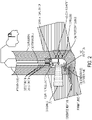
- the tool includes EM generator 1 to generate EM signals 5; EM enabler 2 that is susceptible to heating by the EM signals to cause a temperature of formation 6 to increase from a formation temperature to a target temperature; and rotational motor 3 having multiple sides.
- Rotation of rotational motor 3 having multiple sides is represented by arrow 16.
- the rotational motor may have, two sides, or three sides, or four sides, or five sides.
- the multiple sides can face in different directions.
- the multiple sides can face in opposite directions.
- the rotational motor has two sides.
- the rotational motor includes EM antenna 4 to output EM signals 5 to formation 6 to cause a temperature of the formation to increase from the formation temperature to the target temperature.
- the EM antenna may be on a one side of the multiple sides.
- EM generator 1 feeds power to EM antenna 4 through power cable 9.
- the rotational motor also includes a purging system.
- the purging system includes purging nozzles 7 to apply cooling agent 8 to the formation to cause the temperature of the formation to decrease from the target temperature to a cooling temperature that is closer to a temperature of the cooling agent used in order to create fractures in the formation.
- the purging system may be on a different side of the rotational motor than the EM antenna.
- the purging system and the EM antenna are on opposite sides of the rotational motor; however, this is not a requirement of the tool.
- the tool includes protective casing 10 to encase in whole, or in part, at least the EM generator, the EM antenna, and the EM enabler.
- the casing may be configured, arranged, or configured and arranged to protect the EM generator, the EM antenna, and the EM enabler from physical damage, or chemical damage, or physical and chemical damage, or other environmental or operational dangers.
- the formation temperature may depend on multiple factors including the size of the formation, the type of rock or other materials in the formation, and ambient pressure in the formation.
- the magnitude of the target temperature may depend on factors such as the size of the formation, and the type of rock or other materials in the formation.
- the target temperature may be at least 900 °C, or at least 950 °C, or at least 1,000 °C, or at least 1,050°C, or at least 1,100 °C, or at least 1,200 °C, or at least 1,300 °C, or at least 1,400 °C, or at least 1,500 °C.
- the cooling temperature may depend on various factors, including but not limited to, the type of cooling agent used, and the amount of cooling agent sprayed on the formation.
- the cooling temperature may be the formation temperature.
- the cooling temperature may be at least 50 °C, or at least 100 °C, or at least 150 °C, at least 200 °C, or at least 250 °C, or at least 300 °C, or at least 350 °C, or at least 400 °C, or at least 450 °C, or at least 500 °C, or at least 550 °C, or at least 600 °C.
- the target and cooling temperatures may also be dictated by the size and extent of fractures or cracks to be formed. For example, if the fractures or cracks are to be large and extensive, the temperature differential between the target and cooling temperatures may be larger than in cases where the fractures or cracks are to be less large, less extensive, or both.
- EM generator 1 and EM antenna 4 is located on the rotational tool and are used to generate EM signals 5 downhole in the wellbore.
- EM generator 1 and EM antenna 4 may be fed power by power cable 9 from the surface of wellbore 15 near wellhead 12 to provide electrical energy needed to generate EM signals to heat the formation in the wellbore.
- the EM signals are directed by EM generator 1 and EM antenna 4 to formation 6 in the wellbore that the EM generator and EM antenna faces.
- EM generator 1 is located on the surface of wellbore 15, near to the wellhead.
- the EM signals are delivered through the wellbore using various technologies.
- the EM signals can be delivered to the rotational motor using EM guided antenna 17.
- EM antenna 4 located on one side of rotational motor 3 directs the EM signals through the EM enabler (not shown in Figs. 2 and 3 ) to formation 6 to increase the temperature of the formation from the formation temperature to the target temperature.
- an EM enabler is located alongside EM antenna 4 on rotational motor 3 of the rotational tool.
- the EM enabler is located in close proximity to the EM antenna, and is configured as an EM enabler plate to be placed against the EM antenna.
- EM signals generated by the EM generator are then, for example, directed by the EM antenna through the EM enabler plate, thereby heating the EM enabler and generating high-energy EM signals. These high-energy EM signals contact formation 6 and increase the temperature of the formation from the formation temperature to the target temperature.
- the EM enabler is not located alongside EM antenna 4 on rotational motor 3 of the rotational tool, but is located on formation 6 or in the formation.
- types of EM enabler that may be used with the tool include, but are not limited to, a powder, a slurry, or a putty.
- a slurry includes a substance that is a semi-liquid mixture containing small particles suspend in water.
- a putty includes a substance that is a soft, malleable paste.
- the EM enabler in powdered form may be dispersed in the formation, on the formation, or both in the formation and on the formation to fill pores of the formation around the wellbore.
- the EM signals generated by the generator are then, for example, directed by the EM antenna on or into the formation, causing the EM enabler powder in the pores of the formation to heat-up from the ambient or formation temperature to the target temperature.
- Generated heat 11 shown as arrows in Figs. 2 and 3 ) from the EM enabler at the target temperature contacts the formation and increases the temperature of the formation from the ambient or formation temperature to the target temperature.
- the EM enabler is in the form of a slurry, or a putty.
- a mini-fracture may be created along a circumference of the wellbore using various technologies.
- the width of a mini-fracture is generally in millimeters.
- a mini-fracture may have, but is not limited to, a width of 0.1 millimeter (mm), 0.2 mm, or 0.3 mm.
- regular fractures or cracks are larger.
- regular fractures may have, but is not limited to, a width of greater than 0.5 mm.
- a regular fracture or crack may have a width of 0.5 mm, 0.6 mm, or 1 mm.
- the surface length of an example mini-fracture created along the circumference of the wellbore wall using various technologies may be around a few centimeters.
- Examples of mini-fracture-creating technologies that are usable with the tool may include, but are not limited to, a laser, or a drill.
- the EM enabler is filled into the mini-fracture.
- the EM signals generated by EM generator are then, for example, directed by EM antenna 4 to the formation, causing the EM enabler in the mini-fracture to heat-up from the initial formation temperature to the target temperature or to a temperature that is within an acceptable tolerance of the target temperature.
- the EM enabler can be made from any appropriate materials.
- the EM enabler is a ceramic, an activated carbon, or a combination of a ceramic and an activated carbon.
- these materials can heat-up to relatively high target temperatures, for example around 1000°C, when exposed to EM signals.
- the target temperature as discussed previously, may depend on, but is not limited to, the EM enabler used, the form of the EM enabler, the size of the formation, and the type of rock or other materials in the formation. Examples of target temperature include, but are not limited to, 900°C, 950°C, 1000°C, 1050°C, and 1100°C.
- the rate of change of temperature may depend on multiple factors. For example, the choice of EM enabler material may affect the rate of change of temperature. The rate of change of temperature may also depend on other factors, such as the intensity of the EM signal applied, and the materials in the formation.
- an example purging system includes one or more nozzles on a side of rotational motor 3 that is different from - for example, opposite to - the side of the rotational motor containing the EM antenna 4.
- the purging system may include two, three, four, or any appropriate number of nozzles.
- the nozzles of the purging system can be arranged in different configurations.
- the nozzles may be arranged vertically, horizontally, in a grid, or in any other pattern.
- the nozzles 7 of the purging system are arranged vertically, one on top of the other, parallel to the longitudinal dimension of the tool.
- the nozzles can be arranged horizontally such that they are perpendicular to the longitudinal dimension of the tool.
- the nozzles can be arranged in a grid having a number of rows and columns.
- the purging system is configured to spray, direct, or otherwise output a cooling agent onto the formation that has been heated from the formation temperature to the target temperature.
- Application of the cooling agent decreases the temperature of the heated formation from the target temperature to the cooling temperature, which is a temperature that is closer to the temperature of the cooling agent.
- the one or more nozzles 7 on the other side of the of the rotational motor sprays cooling agent 8 to cool the formation from the target temperature to the cooling temperature closer to temperature of the cooling agent.
- the cooling agent may be in the form of, but is not limited to, a gas, a liquid, and a fluid.
- the cooling temperature may depend on multiple factors, including but not limited to the type of cooling agent used, and the amount of cooling agent sprayed on the formation.
- the type of cooling agent used during the fracturing process may also depend on various parameters, including, but not limited to, the target temperature to be achieved, the rate of temperature decrease desired, and the type of rock or other materials in the formation.
- Examples of cooling agents may include, but are not limited to, one or more of the following: air, nitrogen gas, inert gases, or water.
- the amount of cooling agent used to attain the cooling temperature may depend on a number of factors. These may include, for example, the type of cooling agent used, the cooling temperature desired, the type of rock or other materials in the formation, or the amount of fracturing to be achieved.
- the rotational tool includes detector 13 for monitoring a stimulation of the formation to be fractured.
- the detector may be configured, arranged, or configured and arranged to monitor sounds from generated fractures and cracks in the formation.
- the detector may include, but are not limited to, a detector having acoustic detection capabilities, geophones, or transducers.
- a transducer detects acoustic signals and converts them to electronic signals.
- a geophone detects ground movement and converts it into electronic signals.
- the detector 13 includes at least a transducer that detects acoustic signals and converts the acoustic signals to electronic signals.
- the tool includes multiple transducers.
- the tool may include two, three, four, or more transducers.
- the detector includes at least a geophone that detects ground movement and converts signals representing the ground movement into electronic signals.
- the tool includes multiple geophones.
- the tool may include two, three, four, or more geophones.
- the detector includes at least a transducer and at least a geophone that monitor both acoustic signals and ground movement and convert signals representing sound and ground movement, respectively, into electronic signals.
- the tool includes multiple transducers and multiple geophones.
- the tool may include two, three, four, or more transducers and two, three, four, or more geophones.
- a system including the detector also includes a recorder for recording sounds from generated fractures and cracks in the formation that are detected by the detector.
- the recorder may be configured, arranged, or configured and arranged to record electronic signals that are outputted by the detector.
- the electronic signals may include or be, for example, voltage, current, radio frequency (RF) signals, or acoustic signals.
- the detector and recorder combined may be used, for example, to determine the success and functionality of the fracturing operation.
- Indicators of operational success and functionality may include, for example, but are not limited to, increases in fracture dimensions, and increases in well productivity. Measurement of these indicators may be performed using various technologies.
- the recorder may be located in close proximity to the detector. For example, the recorder may be located on the tool. In some implementations, the recorder may be located on the surface of the wellbore near the wellhead. Then, the recorder may be connected to the detector on the tool through wired or wireless technologies. In an example, the recorder may be connected to the downhole detector via a data cable.
- the recorder for example, may also be connected to a downhole detector located on the tool, through various wireless technologies. For example, the recorder may be connected to the detector located on the tool through Bluetooth, WIFI, or other appropriate technologies.
- the system includes one or more cleaning nozzles to aid in cleaning the fractures generated in the formation.
- the tool may include two, three, four, or more cleaning nozzles 14.
- the cleaning nozzles can be arranged in different configurations.
- the cleaning nozzles may be arranged vertically, horizontally, in a grid pattern, or in any other pattern.
- the cleaning nozzles of the tool are arranged vertically, or one on top of the other, parallel to the longitudinal dimension of the tool.
- cleaning nozzles 14 can be arranged horizontally such that the nozzles are perpendicular to the longitudinal dimension of the tool.
- the nozzles can be arranged in a grid having a finite number of rows and columns.
- the one or more cleaning nozzles may be configured to spray, direct, or otherwise output a cleaning agent onto the fractures in the formation that have been generated from repeated heating and cooling of the formation in the wellbore. Spraying of the cleaning agent onto the fractures in the formation may aid in cleaning the fractures and removing debris from the wellbore.
- Debris in the wellbore may include, for example, fractured rock fragments, mud, and plant roots. Removal of debris from the formation may facilitate, for example, further fracturing of the formation in the wellbore, and extraction of hydrocarbons. Spraying of the cleaning agent on to the fractures in the formation may facilitate removal of hydrocarbons produced from the fractures in the formation of the wellbore, and control of the flow of hydrocarbons out of the fractures. For example, non-removal of debris from the generated fractures may result in the debris such as rock fragments, remaining fracturing fluids, and mud, to plug the generated fractures, thereby preventing the flow of hydrocarbons.
- the one or more cleaning nozzles 14 are located on top of the rotational motor.
- the cleaning nozzles may be located in other locations of the tool.
- the cleaning nozzles may be located downhole, to the side, or elsewhere relative to the rotational motor.
- the cleaning agent may include, but is not limited to, a gas, a liquid, or a fluid.
- the type of cleaning agent used during the fracturing process may depend on various parameters, including but not limited to, the depth of wellbore and the amount of fracturing of the formation the type of rock or other materials in the formation.
- the cleaning agent may include, but is not limited to, one or more of the following: air, nitrogen gas, inert gases, or water.
- the amount of cleaning agent used depends on a number of factors. These factors may include the type of cleaning agent used, the type of rock or other materials in the formation, and the amount of fracturing.
- the tool includes a casing to protect the tool from environmental or operational dangers.
- casing 10 is used to encase, in whole or in part, at least the EM generator, the EM antenna, and the EM enabler.
- the casing may be configured, arranged, or configured and arranged to protect the EM generator, the EM antenna, and the EM enabler from physical or electromagnetic damage.
- the casing can be used to encase and, therefore, to protect additional components of the tool. These additional components may include, but are not limited to, the one or more detectors located on the tool, the one or more recorders located on the tool, and additional wireless or wired technologies located on the tool.
- the threat of physical damage to components of the tool may be due to elements contained in the formation or components that are part of the tool itself.
- elements of the formation that can cause physical damage to the tool include, but are not limited to, debris generated in the formation due to fracturing of the formation in the wellbore, or hydrocarbons in the formation generated from fractures in the formation in the wellbore.
- components of the tool that can cause physical damage to the tool include, but are not limited to, the cooling agent, or the cleaning agent.
- the casing is made of a material that is transparent to EM signals generated and transmitted by the encased EM generator and EM antenna.
- the casing is made of a material that is transparent to both the EM signals and the heat generated and transmitted by the encased EM generator, EM antenna, and EM enabler. Examples of materials used in the casing include, but are not limited to, plastic, glass, or stainless steel.
- the material used to make the casing may be selected for its strength and its ability to handle extreme heat - for example up to the target temperature - and a rapid rate of change in temperature in the wellbore during the operation of the tool.
- the casing may be a pipe.
- the pipe may have a circular cross-section, or a rectangular cross-section, or an ovoid cross-section.
- the dimensions of the pipe may depend on various factors including, but not limited to, the type of wellbore, the depth of the wellbore, or the production capacity of the wellbore.
- a diameter of a circular cross-sectional pipe casing may include, but is not limited to, at least four inches, or at least five inches, or at least six inches, or at least seven inches, or at least eight inches, or at least nine inches, or at least ten inches.
- the time needed to heat and to generate fractures in a formation of a wellbore may vary based on a number of conditions. These may include, but are not limited to, the formation temperature, the target temperature, the cooling agent used, the intensity of the EM signal, the type of rock or other materials in the formation, the electric properties of the formation, and the EM enabler. For example, it may take five minutes, ten minutes, twenty minutes, or thirty minutes, or more, for the tool to stimulate thermal shocks in the formation by rapid heating and cooling of the formation in the wellbore. The tool, however, is not limited to these durations.
- the number of generated fractures in the formation of the wellbore may be different for different formations.
- the rate of fracture generation may depend on various factors. These include, but are not limited to, the type of rock or other materials in the formation, the number of thermal cycles, the cooling agent used, and the intensity of the EM signals applied.
- generating fractures in the formation of a wellbore may include generating smaller superficial fractures on a surface of the formation in the wellbore.
- generating fractures in the formation of a wellbore may include generating large deep fractures in the interior of the formation.
- the depth of a fracture generated by the tool may depend on multiple factors including, but not limited to, the type of rock or other materials in the formation, the number of thermal cycles, the cooling agent used, and the intensity of the EM signals applied.
- a process 30 is shown for heating and stimulating fractures in a formation of a wellbore, and for producing at least part of a well using the techniques described previously.
- Operation 31 includes identifying a reservoir to be fractured.
- Operation 32 includes lowering the rotational motor of the tool into the wellbore. Examples of the tool are described throughout this specification.
- An example of the tool in a wellbore is shown in Figs. 2 and 3 .
- Operation 33 includes using one side of the rotational motor in the wellbore to direct EM signals through an EM enabler to the formation to heat the formation in a wellbore from the formation temperature to the target temperature.
- FIG. 2 shows the rotational motor in a wellbore having a downhole EM generator and antenna.
- Fig. 3 shows the rotational motor in a wellbore with a surface EM generator 1.
- the EM signals generated by the surface or the downhole EM generator unit are directed through an EM enabler to the formation to increase the temperature of the formation in a wellbore from the formation temperature to the target temperature.
- Operation 34 includes rotating the tool so that the purging system faces the part of the formation that was heated using the EM signals, and cooling the heated formation by outputting a cooling agent from the purging system.
- Techniques for applying, via the purging system, a cooling agent to the heated part of the formation are described previously. As shown in Figs. 2 and 3 , the cooling agent is applied to the heated formation to decrease the temperature of the formation in the wellbore from the target temperature to the cooling temperature, resulting in thermal shocking of the formation in the wellbore.
- Operation 35 includes repeating, as necessary or desired, the operations of heating and cooling the formation by rotating the tool in the wellbore to heat and to cool the part of the formation alternately. The heating and cooling cycles or the thermal cycling is repeated to produce repeated thermal shocks in the formation in the wellbore. The repeated thermal shocks to the formation in the wellbore result in fracture formation and propagation along at least part of a circumference of the wellbore.
- Operation 36 includes removing debris from the wellbore using the cleaning nozzles configured to spray a cleaning agent.
- one or more cleaning nozzles may spray a cleaning fluid that aid in removal of debris from the wellbore. This may aid, as mentioned previously, in the operation for implementing continued, uninterrupted fracturing of the formation in the wellbore.
- spraying of the cleaning agent onto the fractures in the formation may also be used to facilitate removal of hydrocarbons from the fractures in the formation, and to control the flow of hydrocarbons out of the fractures in the formation of the wellbore.
- Operation 37 includes determining if thermal cycling and, therefore, the thermal shocking of the formation in the wellbore are to be repeated to achieve a target fracturing of the formation in the wellbore.
- operation 38 includes removing the tool from the wellbore.
- the example tools and processes described previously may be implemented in wellbores that are, in whole or part, non-vertical.
- the example tools and processes may be performed for a fracture that occurs in a deviated wellbore, a horizontal wellbore, or a partially horizontal wellbore, where horizontal is measured relative to the Earth's surface in some examples.
- All or part of the example tools and processes described in this specification and their various modifications may be controlled at least in part, by one or more computers using one or more computer programs tangibly embodied in one or more information carriers, such as in one or more non-transitory machine-readable storage media.
- a computer program can be written in any form of programming language, including compiled or interpreted languages, and it can be deployed in any form, including as a stand-alone program or as a module, part, subroutine, or other unit suitable for use in a computing environment.
- a computer program can be deployed to be executed on one computer or on multiple computers at one site or distributed across multiple sites and interconnected by a network.
- Actions associated with controlling the processes can be performed by one or more programmable processors executing one or more computer programs to control all or some of the well formation operations described previously. All or part of the processes can be controlled by special purpose logic circuitry, such as, an FPGA (field programmable gate array), an ASIC (application-specific integrated circuit), or both an FPGA and an ASIC.
- special purpose logic circuitry such as, an FPGA (field programmable gate array), an ASIC (application-specific integrated circuit), or both an FPGA and an ASIC.
- processors suitable for the execution of a computer program include, by way of example, both general and special purpose microprocessors, and any one or more processors of any kind of digital computer.
- a processor will receive instructions and data from a read-only storage area or a random access storage area or both.
- Elements of a computer include one or more processors for executing instructions and one or more storage area devices for storing instructions and data.
- a computer will also include, or be operatively coupled to receive data from, or transfer data to, or both, one or more machine-readable storage media, such as mass storage devices for storing data, such as magnetic, magneto-optical disks, or optical disks.
- Non-transitory machine-readable storage media suitable for embodying computer program instructions and data include all forms of non-volatile storage area, including by way of example, semiconductor storage area devices, such as EPROM (erasable programmable read-only memory), EEPROM (electrically erasable programmable read-only memory), and flash storage area devices; magnetic disks, such as internal hard disks or removable disks; magneto-optical disks; and CD-ROM (compact disc read-only memory) and DVD-ROM (digital versatile disc read-only memory).
- semiconductor storage area devices such as EPROM (erasable programmable read-only memory), EEPROM (electrically erasable programmable read-only memory), and flash storage area devices
- magnetic disks such as internal hard disks or removable disks
- magneto-optical disks magneto-optical disks
- CD-ROM compact disc read-only memory
- DVD-ROM digital versatile disc read-only memory
Landscapes
- Life Sciences & Earth Sciences (AREA)
- Engineering & Computer Science (AREA)
- Geology (AREA)
- Mining & Mineral Resources (AREA)
- Physics & Mathematics (AREA)
- Environmental & Geological Engineering (AREA)
- Fluid Mechanics (AREA)
- General Life Sciences & Earth Sciences (AREA)
- Geochemistry & Mineralogy (AREA)
- Geophysics And Detection Of Objects (AREA)
- Investigating Or Analyzing Materials By The Use Of Ultrasonic Waves (AREA)
Claims (15)
- System, das Folgendes umfasst:einen Generator (1) zum Erzeugen elektromagnetischer Signale (EM-Signale); undeine Drehvorrichtung, die konfiguriert ist, in einem Bohrloch (15) zu arbeiten, wobei die Drehvorrichtung eine Antenne (4) aufweist, um die EM-Signale in eine Formation (6) zu lenken, um eine Temperatur der Formation von einer ersten Temperatur auf eine zweite Temperatur zu erhöhen, wobei die EM-Signale Mikrowellen und/oder Funkfrequenzsignale (RF-Signale) und/oder Infrarotsignale (IR-Signale) und/oder Ultraviolettsignale (UV-Signale) und/oder Röntgenstrahlen umfassen,dadurch gekennzeichnet, dassdie Drehvorrichtung mehrere Seiten aufweist, wobei sich die Antenne auf einer ersten Seite der mehreren Seiten befindet, unddie Drehvorrichtung ferner ein Spülsystem (7) aufweist, um in die Formation ein Kühlungsmittel einzubringen, um zu bewirken, dass die Temperatur der Formation von der zweiten Temperatur auf eine dritte Temperatur abnimmt, um dadurch Risse in der Formation zu erzeugen, wobei sich das Spülsystem auf einer zweiten Seite der mehreren Seiten befindet, wobei die zweite Seite in eine andere Richtung als die erste Seite weist.
- System nach Anspruch 1, das ferner Folgendes umfasst:
ein Ermöglichungsmittel (2), das durch die EM-Signale erwärmt werden kann, um die Erhöhung der Temperatur der Formation von der ersten Temperatur auf die zweite Temperatur zu unterstützen. - System nach Anspruch 1, das ferner Folgendes umfasst:einen Detektor (13) zum Detektieren von Schall in der Formation; undeine Aufzeichnungseinrichtung, um Informationen, die den Schall repräsentieren, aufzuzeichnen.
- System nach Anspruch 2, das ferner eine oder mehrere Reinigungsdüsen (14) umfasst, die konfiguriert sind, ein Reinigungsmittel auszugeben, um Kohlenwasserstoffe aus den Rissen freizusetzen und um eine Strömung der Kohlenwasserstoffe aus den Rissen zu steuern, und/oder
ferner ein Gehäuse (10) umfasst, um wenigstens die Antenne (4) und das Ermöglichungsmittel (2) vor einer physischen Beschädigung zu schützen. - System nach Anspruch 1, wobei die erste Seite und die zweite Seite in entgegengesetzte Richtungen weisen und/oder
wobei die Drehvorrichtung konfiguriert ist, sich mit einer Drehzahl zu drehen und eine Anzahl von Erwärmungs- und Kühlungszyklen auszuführen, wobei das Erwärmen von der ersten Seite der mehreren Seiten her erfolgt und das Kühlen von der zweiten Seite der mehreren Seiten her erfolgt. - System nach Anspruch 3, wobei der Detektor (13) wenigstens einen Messwandler und/oder wenigstens ein Geophon oder wenigstens einen Messwandler und wenigstens ein Geophon umfasst und wobei optionalder Messwandler konfiguriert ist, den Schall von den erzeugten Rissen zu überwachen und/oderwobei das Geophon konfiguriert ist, Bodenbewegungen von den erzeugten Rissen zu überwachen.
- System nach Anspruch 1, wobei der Generator eine Bohrlocheinheit, die sich in einem Bohrloch befindet, umfasst oder
wobei der Generator (1) eine Oberflächeneinheit, die sich an einer Oberfläche eines Bohrlochs befindet, umfasst, wobei der Generator (1) optional ferner eine geführte Antenne umfasst, um die EM-Signale in das Bohrloch auszugeben. - System nach Anspruch 2, wobei das Ermöglichungsmittel (2) Keramik, Aktivkohle oder eine Kombination aus Keramik und Aktivkohle enthält und/oder
wobei sich das Ermöglichungsmittel (2) in der Nähe der Antenne (4) befindet, wobei sich das Ermöglichungsmittel (2) und die Antenne (4) auf einer ersten Seite der mehreren Seiten der Drehvorrichtung befinden. - System nach Anspruch 2, wobei sich das Ermöglichungsmittel (2) außerhalb der Drehvorrichtung befindet und in die Formation eingebracht wird und wobei optional
das Ermöglichungsmittel (2) ein Pulver oder einen Schlamm oder einen Kitt oder eine Kombination aus einem Pulver und einem Schlamm oder eine Kombination aus einem Schlamm und einem Kitt oder eine Kombination aus einem Pulver und einem Kitt oder eine Kombination aus einem Pulver, einem Schlamm und einem Kitt umfasst. - Verfahren zum Erzeugen von Rissen in einer Formation, wobei das Verfahren Folgendes umfasst:Erzeugen elektromagnetischer Signale (EM-Signale);Lenken über eine Antenne (4) der EM-Signale durch ein Ermöglichungsmittel (2), das durch die EM-Signale erwärmt werden kann, um zu bewirken, dass eine Temperatur einer Formation (6) von einer ersten Temperatur auf eine zweite Temperatur ansteigt, wobei sich die Antenne auf einer ersten Seite einer Drehvorrichtung befindet,dadurch gekennzeichnet, dass die Drehvorrichtung mehrere Seiten einschließlich der ersten Seite aufweist und dass das Verfahren ferner Folgendes umfasst:Drehen der Drehvorrichtung; undEinbringen über ein Spülsystem (7) eines Kühlungsmittel in die Formation, um zu bewirken, dass die Temperatur der Formation (6) von der zweiten Temperatur auf eine dritte Temperatur abnimmt, um dadurch Risse in der Formation (6) zu erzeugen, wobei sich das Spülsystem auf einer zweiten Seite der mehreren Seite der Drehvorrichtung befindet, wobei die zweite Seite von der ersten Seite verschieden ist.
- Verfahren nach Anspruch 10, das ferner Folgendes umfasst:Überwachen von Schallsignalen in der Formation; undAufzeichnen der Schallsignale.
- Verfahren nach Anspruch 10, das ferner das Erzeugen der EM-Signale unter Verwendung eines Generators (1) umfasst, wobei optionaldie EM-Signale an einer Oberfläche eines Bohrlochs (15) erzeugt werden oderdie EM-Signale in einem Bohrloch (15) erzeugt werden.
- Verfahren nach Anspruch 10, wobei das Ermöglichungsmittel (2) in einer Pulverform in die Formation (6) eingeleitet wird, um Formationsporen zu füllen, und/oder
wobei das Ermöglichungsmittel in einen Kleinstriss, der längs des Umfangs eines Bohrlochs erzeugt wird, gefüllt wird, wobei der Kleinstriss optional unter Verwendung eines Lasers erzeugt wird. - Verfahren nach Anspruch 10, wobei die erste Temperatur eine Formationstemperatur ist.
- Verfahren nach Anspruch 10, wobei die zweite Temperatur größer als 1000 °C ist oder
wobei die zweite Temperatur kleiner als 1000 °C ist.
Applications Claiming Priority (2)
| Application Number | Priority Date | Filing Date | Title |
|---|---|---|---|
| US15/970,604 US10920549B2 (en) | 2018-05-03 | 2018-05-03 | Creating fractures in a formation using electromagnetic signals |
| PCT/IB2018/057292 WO2019211656A1 (en) | 2018-05-03 | 2018-09-21 | Creating fractures in a formation using electromagnetic signals |
Publications (2)
| Publication Number | Publication Date |
|---|---|
| EP3788231A1 EP3788231A1 (de) | 2021-03-10 |
| EP3788231B1 true EP3788231B1 (de) | 2022-05-18 |
Family
ID=63794574
Family Applications (1)
| Application Number | Title | Priority Date | Filing Date |
|---|---|---|---|
| EP18783133.4A Active EP3788231B1 (de) | 2018-05-03 | 2018-09-21 | Erstellen von frakturen in einer formation mit elektromagnetischen signalen |
Country Status (6)
| Country | Link |
|---|---|
| US (1) | US10920549B2 (de) |
| EP (1) | EP3788231B1 (de) |
| CA (1) | CA3099027C (de) |
| MA (1) | MA52456A (de) |
| SA (1) | SA520420471B1 (de) |
| WO (1) | WO2019211656A1 (de) |
Families Citing this family (6)
| Publication number | Priority date | Publication date | Assignee | Title |
|---|---|---|---|---|
| US10704371B2 (en) * | 2017-10-13 | 2020-07-07 | Chevron U.S.A. Inc. | Low dielectric zone for hydrocarbon recovery by dielectric heating |
| CN110924916B (zh) * | 2019-12-12 | 2024-11-22 | 上海瑞达峰致能源科技股份有限公司 | 一种提高致密页岩油气储层渗透率的装置 |
| WO2021242673A1 (en) * | 2020-05-26 | 2021-12-02 | Saudi Arabian Oil Company | Using radio waves to fracture rocks in a hydrocarbon reservoir |
| US20220106869A1 (en) * | 2020-10-02 | 2022-04-07 | Saudi Arabian Oil Company | Breakdown pressure reduction based on injection of cooling agents |
| US11603728B1 (en) * | 2021-11-18 | 2023-03-14 | Saudi Arabian Oil Company | Laser and chemical system and methods for well stimulation and scale removal |
| GB2624407B (en) * | 2022-11-16 | 2025-05-21 | Cavitas Energy Ltd | A method of deploying a fluid heater downhole |
Family Cites Families (13)
| Publication number | Priority date | Publication date | Assignee | Title |
|---|---|---|---|---|
| US3638727A (en) * | 1968-09-27 | 1972-02-01 | Texaco Inc | Method of treating a subterranean hydrocarbon-bearing formation |
| US3759329A (en) * | 1969-05-09 | 1973-09-18 | Shuffman O | Cryo-thermal process for fracturing rock formations |
| US3602310A (en) | 1970-01-15 | 1971-08-31 | Tenneco Oil Co | Method of increasing the permeability of a subterranean hydrocarbon bearing formation |
| US5003144A (en) | 1990-04-09 | 1991-03-26 | The United States Of America As Represented By The Secretary Of The Interior | Microwave assisted hard rock cutting |
| US5539853A (en) | 1994-08-01 | 1996-07-23 | Noranda, Inc. | Downhole heating system with separate wiring cooling and heating chambers and gas flow therethrough |
| CA2592491C (en) | 2006-05-30 | 2016-06-07 | Peter M. Kearl | Microwave process for intrinsic permeability enhancement and hydrocarbon extraction from subsurface deposits |
| EP2324193B1 (de) * | 2008-05-19 | 2017-01-11 | Halliburton Energy Services, Inc. | Elektromagnetische strahlung verwendende formationsbehandlung |
| US10073184B2 (en) * | 2012-02-06 | 2018-09-11 | Ion Geophysical Corporation | Sensor system of buried seismic array |
| US9644464B2 (en) * | 2013-07-18 | 2017-05-09 | Saudi Arabian Oil Company | Electromagnetic assisted ceramic materials for heavy oil recovery and in-situ steam generation |
| CA2958718C (en) | 2014-06-17 | 2022-06-14 | Daniel Robert MCCORMACK | Hydraulic drilling systems and methods |
| US9896619B2 (en) * | 2015-12-08 | 2018-02-20 | Halliburton Energy Services, Inc. | Enhancing conductivity of microfractures |
| US9896919B1 (en) * | 2016-08-22 | 2018-02-20 | Saudi Arabian Oil Company | Using radio waves to fracture rocks in a hydrocarbon reservoir |
| US10253608B2 (en) * | 2017-03-14 | 2019-04-09 | Saudi Arabian Oil Company | Downhole heat orientation and controlled fracture initiation using electromagnetic assisted ceramic materials |
-
2018
- 2018-05-03 US US15/970,604 patent/US10920549B2/en active Active
- 2018-09-21 WO PCT/IB2018/057292 patent/WO2019211656A1/en not_active Ceased
- 2018-09-21 MA MA052456A patent/MA52456A/fr unknown
- 2018-09-21 EP EP18783133.4A patent/EP3788231B1/de active Active
- 2018-09-21 CA CA3099027A patent/CA3099027C/en active Active
-
2020
- 2020-11-03 SA SA520420471A patent/SA520420471B1/ar unknown
Also Published As
| Publication number | Publication date |
|---|---|
| US20190338625A1 (en) | 2019-11-07 |
| CA3099027C (en) | 2025-06-10 |
| EP3788231A1 (de) | 2021-03-10 |
| MA52456A (fr) | 2021-03-10 |
| SA520420471B1 (ar) | 2024-05-21 |
| WO2019211656A1 (en) | 2019-11-07 |
| US10920549B2 (en) | 2021-02-16 |
| CA3099027A1 (en) | 2019-11-07 |
Similar Documents
| Publication | Publication Date | Title |
|---|---|---|
| EP3788231B1 (de) | Erstellen von frakturen in einer formation mit elektromagnetischen signalen | |
| US10253608B2 (en) | Downhole heat orientation and controlled fracture initiation using electromagnetic assisted ceramic materials | |
| US10746006B2 (en) | Plasma sources, systems, and methods for stimulating wells, deposits and boreholes | |
| EP2235321B1 (de) | Stimulation durch spaltenbildung beim bohren | |
| US10760396B2 (en) | Using radio waves to fracture rocks in a hydrocarbon reservoir | |
| CN105392954B (zh) | 使用高功率激光束的井下深层隧道掘进工具和方法 | |
| US6227293B1 (en) | Process and apparatus for coupled electromagnetic and acoustic stimulation of crude oil reservoirs using pulsed power electrohydraulic and electromagnetic discharge | |
| EP2935754A1 (de) | Repetitive gepulste stromentladungsvorrichtungen und verfahren zur verwendung | |
| CN110036179A (zh) | 井下井筒高功率激光加热压裂增产处理和方法 | |
| US11739616B1 (en) | Forming perforation tunnels in a subterranean formation | |
| US20240401445A1 (en) | Interventions to Boost Well Performance in Geothermal Systems | |
| US20260028968A1 (en) | Intervention combinations to boost well performance in geothermal systems | |
| US10920556B2 (en) | Using radio waves to fracture rocks in a hydrocarbon reservoir | |
| WO2024249643A1 (en) | Interventions to boost well performance in geothermal systems | |
| Batarseh et al. | Applying High Power Laser Technology in Well Completion |
Legal Events
| Date | Code | Title | Description |
|---|---|---|---|
| STAA | Information on the status of an ep patent application or granted ep patent |
Free format text: STATUS: UNKNOWN |
|
| STAA | Information on the status of an ep patent application or granted ep patent |
Free format text: STATUS: THE INTERNATIONAL PUBLICATION HAS BEEN MADE |
|
| PUAI | Public reference made under article 153(3) epc to a published international application that has entered the european phase |
Free format text: ORIGINAL CODE: 0009012 |
|
| STAA | Information on the status of an ep patent application or granted ep patent |
Free format text: STATUS: REQUEST FOR EXAMINATION WAS MADE |
|
| 17P | Request for examination filed |
Effective date: 20201201 |
|
| AK | Designated contracting states |
Kind code of ref document: A1 Designated state(s): AL AT BE BG CH CY CZ DE DK EE ES FI FR GB GR HR HU IE IS IT LI LT LU LV MC MK MT NL NO PL PT RO RS SE SI SK SM TR |
|
| AX | Request for extension of the european patent |
Extension state: BA ME |
|
| RAV | Requested validation state of the european patent: fee paid |
Extension state: MA Effective date: 20201201 Extension state: MD Effective date: 20201201 |
|
| GRAP | Despatch of communication of intention to grant a patent |
Free format text: ORIGINAL CODE: EPIDOSNIGR1 |
|
| STAA | Information on the status of an ep patent application or granted ep patent |
Free format text: STATUS: GRANT OF PATENT IS INTENDED |
|
| INTG | Intention to grant announced |
Effective date: 20211201 |
|
| GRAS | Grant fee paid |
Free format text: ORIGINAL CODE: EPIDOSNIGR3 |
|
| GRAA | (expected) grant |
Free format text: ORIGINAL CODE: 0009210 |
|
| STAA | Information on the status of an ep patent application or granted ep patent |
Free format text: STATUS: THE PATENT HAS BEEN GRANTED |
|
| AK | Designated contracting states |
Kind code of ref document: B1 Designated state(s): AL AT BE BG CH CY CZ DE DK EE ES FI FR GB GR HR HU IE IS IT LI LT LU LV MC MK MT NL NO PL PT RO RS SE SI SK SM TR |
|
| REG | Reference to a national code |
Ref country code: GB Ref legal event code: FG4D |
|
| REG | Reference to a national code |
Ref country code: CH Ref legal event code: EP |
|
| REG | Reference to a national code |
Ref country code: IE Ref legal event code: FG4D |
|
| REG | Reference to a national code |
Ref country code: DE Ref legal event code: R096 Ref document number: 602018035808 Country of ref document: DE |
|
| REG | Reference to a national code |
Ref country code: AT Ref legal event code: REF Ref document number: 1493259 Country of ref document: AT Kind code of ref document: T Effective date: 20220615 |
|
| REG | Reference to a national code |
Ref country code: NO Ref legal event code: T2 Effective date: 20220518 |
|
| REG | Reference to a national code |
Ref country code: LT Ref legal event code: MG9D |
|
| REG | Reference to a national code |
Ref country code: NL Ref legal event code: MP Effective date: 20220518 |
|
| REG | Reference to a national code |
Ref country code: AT Ref legal event code: MK05 Ref document number: 1493259 Country of ref document: AT Kind code of ref document: T Effective date: 20220518 |
|
| PG25 | Lapsed in a contracting state [announced via postgrant information from national office to epo] |
Ref country code: SE Free format text: LAPSE BECAUSE OF FAILURE TO SUBMIT A TRANSLATION OF THE DESCRIPTION OR TO PAY THE FEE WITHIN THE PRESCRIBED TIME-LIMIT Effective date: 20220518 Ref country code: PT Free format text: LAPSE BECAUSE OF FAILURE TO SUBMIT A TRANSLATION OF THE DESCRIPTION OR TO PAY THE FEE WITHIN THE PRESCRIBED TIME-LIMIT Effective date: 20220919 Ref country code: NL Free format text: LAPSE BECAUSE OF FAILURE TO SUBMIT A TRANSLATION OF THE DESCRIPTION OR TO PAY THE FEE WITHIN THE PRESCRIBED TIME-LIMIT Effective date: 20220518 Ref country code: LT Free format text: LAPSE BECAUSE OF FAILURE TO SUBMIT A TRANSLATION OF THE DESCRIPTION OR TO PAY THE FEE WITHIN THE PRESCRIBED TIME-LIMIT Effective date: 20220518 Ref country code: HR Free format text: LAPSE BECAUSE OF FAILURE TO SUBMIT A TRANSLATION OF THE DESCRIPTION OR TO PAY THE FEE WITHIN THE PRESCRIBED TIME-LIMIT Effective date: 20220518 Ref country code: GR Free format text: LAPSE BECAUSE OF FAILURE TO SUBMIT A TRANSLATION OF THE DESCRIPTION OR TO PAY THE FEE WITHIN THE PRESCRIBED TIME-LIMIT Effective date: 20220819 Ref country code: FI Free format text: LAPSE BECAUSE OF FAILURE TO SUBMIT A TRANSLATION OF THE DESCRIPTION OR TO PAY THE FEE WITHIN THE PRESCRIBED TIME-LIMIT Effective date: 20220518 Ref country code: BG Free format text: LAPSE BECAUSE OF FAILURE TO SUBMIT A TRANSLATION OF THE DESCRIPTION OR TO PAY THE FEE WITHIN THE PRESCRIBED TIME-LIMIT Effective date: 20220818 Ref country code: AT Free format text: LAPSE BECAUSE OF FAILURE TO SUBMIT A TRANSLATION OF THE DESCRIPTION OR TO PAY THE FEE WITHIN THE PRESCRIBED TIME-LIMIT Effective date: 20220518 |
|
| PG25 | Lapsed in a contracting state [announced via postgrant information from national office to epo] |
Ref country code: RS Free format text: LAPSE BECAUSE OF FAILURE TO SUBMIT A TRANSLATION OF THE DESCRIPTION OR TO PAY THE FEE WITHIN THE PRESCRIBED TIME-LIMIT Effective date: 20220518 Ref country code: PL Free format text: LAPSE BECAUSE OF FAILURE TO SUBMIT A TRANSLATION OF THE DESCRIPTION OR TO PAY THE FEE WITHIN THE PRESCRIBED TIME-LIMIT Effective date: 20220518 Ref country code: LV Free format text: LAPSE BECAUSE OF FAILURE TO SUBMIT A TRANSLATION OF THE DESCRIPTION OR TO PAY THE FEE WITHIN THE PRESCRIBED TIME-LIMIT Effective date: 20220518 Ref country code: IS Free format text: LAPSE BECAUSE OF FAILURE TO SUBMIT A TRANSLATION OF THE DESCRIPTION OR TO PAY THE FEE WITHIN THE PRESCRIBED TIME-LIMIT Effective date: 20220918 |
|
| PG25 | Lapsed in a contracting state [announced via postgrant information from national office to epo] |
Ref country code: SM Free format text: LAPSE BECAUSE OF FAILURE TO SUBMIT A TRANSLATION OF THE DESCRIPTION OR TO PAY THE FEE WITHIN THE PRESCRIBED TIME-LIMIT Effective date: 20220518 Ref country code: SK Free format text: LAPSE BECAUSE OF FAILURE TO SUBMIT A TRANSLATION OF THE DESCRIPTION OR TO PAY THE FEE WITHIN THE PRESCRIBED TIME-LIMIT Effective date: 20220518 Ref country code: RO Free format text: LAPSE BECAUSE OF FAILURE TO SUBMIT A TRANSLATION OF THE DESCRIPTION OR TO PAY THE FEE WITHIN THE PRESCRIBED TIME-LIMIT Effective date: 20220518 Ref country code: ES Free format text: LAPSE BECAUSE OF FAILURE TO SUBMIT A TRANSLATION OF THE DESCRIPTION OR TO PAY THE FEE WITHIN THE PRESCRIBED TIME-LIMIT Effective date: 20220518 Ref country code: EE Free format text: LAPSE BECAUSE OF FAILURE TO SUBMIT A TRANSLATION OF THE DESCRIPTION OR TO PAY THE FEE WITHIN THE PRESCRIBED TIME-LIMIT Effective date: 20220518 Ref country code: DK Free format text: LAPSE BECAUSE OF FAILURE TO SUBMIT A TRANSLATION OF THE DESCRIPTION OR TO PAY THE FEE WITHIN THE PRESCRIBED TIME-LIMIT Effective date: 20220518 Ref country code: CZ Free format text: LAPSE BECAUSE OF FAILURE TO SUBMIT A TRANSLATION OF THE DESCRIPTION OR TO PAY THE FEE WITHIN THE PRESCRIBED TIME-LIMIT Effective date: 20220518 |
|
| VS25 | Lapsed in a validation state [announced via postgrant information from nat. office to epo] |
Ref country code: MD Free format text: LAPSE BECAUSE OF FAILURE TO SUBMIT A TRANSLATION OF THE DESCRIPTION OR TO PAY THE FEE WITHIN THE PRESCRIBED TIME-LIMIT Effective date: 20220518 |
|
| REG | Reference to a national code |
Ref country code: DE Ref legal event code: R097 Ref document number: 602018035808 Country of ref document: DE |
|
| PLBE | No opposition filed within time limit |
Free format text: ORIGINAL CODE: 0009261 |
|
| STAA | Information on the status of an ep patent application or granted ep patent |
Free format text: STATUS: NO OPPOSITION FILED WITHIN TIME LIMIT |
|
| PG25 | Lapsed in a contracting state [announced via postgrant information from national office to epo] |
Ref country code: AL Free format text: LAPSE BECAUSE OF FAILURE TO SUBMIT A TRANSLATION OF THE DESCRIPTION OR TO PAY THE FEE WITHIN THE PRESCRIBED TIME-LIMIT Effective date: 20220518 |
|
| REG | Reference to a national code |
Ref country code: DE Ref legal event code: R119 Ref document number: 602018035808 Country of ref document: DE |
|
| 26N | No opposition filed |
Effective date: 20230221 |
|
| PG25 | Lapsed in a contracting state [announced via postgrant information from national office to epo] |
Ref country code: MC Free format text: LAPSE BECAUSE OF FAILURE TO SUBMIT A TRANSLATION OF THE DESCRIPTION OR TO PAY THE FEE WITHIN THE PRESCRIBED TIME-LIMIT Effective date: 20220518 |
|
| REG | Reference to a national code |
Ref country code: CH Ref legal event code: PL |
|
| REG | Reference to a national code |
Ref country code: BE Ref legal event code: MM Effective date: 20220930 |
|
| PG25 | Lapsed in a contracting state [announced via postgrant information from national office to epo] |
Ref country code: SI Free format text: LAPSE BECAUSE OF FAILURE TO SUBMIT A TRANSLATION OF THE DESCRIPTION OR TO PAY THE FEE WITHIN THE PRESCRIBED TIME-LIMIT Effective date: 20220518 |
|
| PG25 | Lapsed in a contracting state [announced via postgrant information from national office to epo] |
Ref country code: LU Free format text: LAPSE BECAUSE OF NON-PAYMENT OF DUE FEES Effective date: 20220921 |
|
| P01 | Opt-out of the competence of the unified patent court (upc) registered |
Effective date: 20230526 |
|
| PG25 | Lapsed in a contracting state [announced via postgrant information from national office to epo] |
Ref country code: LI Free format text: LAPSE BECAUSE OF NON-PAYMENT OF DUE FEES Effective date: 20220930 Ref country code: IE Free format text: LAPSE BECAUSE OF NON-PAYMENT OF DUE FEES Effective date: 20220921 Ref country code: FR Free format text: LAPSE BECAUSE OF NON-PAYMENT OF DUE FEES Effective date: 20220930 Ref country code: DE Free format text: LAPSE BECAUSE OF NON-PAYMENT OF DUE FEES Effective date: 20230401 Ref country code: CH Free format text: LAPSE BECAUSE OF NON-PAYMENT OF DUE FEES Effective date: 20220930 |
|
| PG25 | Lapsed in a contracting state [announced via postgrant information from national office to epo] |
Ref country code: BE Free format text: LAPSE BECAUSE OF NON-PAYMENT OF DUE FEES Effective date: 20220930 |
|
| PG25 | Lapsed in a contracting state [announced via postgrant information from national office to epo] |
Ref country code: IT Free format text: LAPSE BECAUSE OF FAILURE TO SUBMIT A TRANSLATION OF THE DESCRIPTION OR TO PAY THE FEE WITHIN THE PRESCRIBED TIME-LIMIT Effective date: 20220518 |
|
| PG25 | Lapsed in a contracting state [announced via postgrant information from national office to epo] |
Ref country code: CY Free format text: LAPSE BECAUSE OF FAILURE TO SUBMIT A TRANSLATION OF THE DESCRIPTION OR TO PAY THE FEE WITHIN THE PRESCRIBED TIME-LIMIT Effective date: 20220511 |
|
| PG25 | Lapsed in a contracting state [announced via postgrant information from national office to epo] |
Ref country code: MK Free format text: LAPSE BECAUSE OF FAILURE TO SUBMIT A TRANSLATION OF THE DESCRIPTION OR TO PAY THE FEE WITHIN THE PRESCRIBED TIME-LIMIT Effective date: 20220511 Ref country code: HU Free format text: LAPSE BECAUSE OF FAILURE TO SUBMIT A TRANSLATION OF THE DESCRIPTION OR TO PAY THE FEE WITHIN THE PRESCRIBED TIME-LIMIT; INVALID AB INITIO Effective date: 20180921 |
|
| PG25 | Lapsed in a contracting state [announced via postgrant information from national office to epo] |
Ref country code: MT Free format text: LAPSE BECAUSE OF FAILURE TO SUBMIT A TRANSLATION OF THE DESCRIPTION OR TO PAY THE FEE WITHIN THE PRESCRIBED TIME-LIMIT Effective date: 20220511 |
|
| PG25 | Lapsed in a contracting state [announced via postgrant information from national office to epo] |
Ref country code: BG Free format text: LAPSE BECAUSE OF FAILURE TO SUBMIT A TRANSLATION OF THE DESCRIPTION OR TO PAY THE FEE WITHIN THE PRESCRIBED TIME-LIMIT Effective date: 20220518 |
|
| PG25 | Lapsed in a contracting state [announced via postgrant information from national office to epo] |
Ref country code: BG Free format text: LAPSE BECAUSE OF FAILURE TO SUBMIT A TRANSLATION OF THE DESCRIPTION OR TO PAY THE FEE WITHIN THE PRESCRIBED TIME-LIMIT Effective date: 20220518 |
|
| PGFP | Annual fee paid to national office [announced via postgrant information from national office to epo] |
Ref country code: NO Payment date: 20250929 Year of fee payment: 8 |
|
| PGFP | Annual fee paid to national office [announced via postgrant information from national office to epo] |
Ref country code: GB Payment date: 20250929 Year of fee payment: 8 |
|
| VS25 | Lapsed in a validation state [announced via postgrant information from nat. office to epo] |
Ref country code: MA Free format text: FAILURE TO ELECT DOMICILE IN THE NATIONAL COUNTRY Effective date: 20220819 |
|
| PG25 | Lapsed in a contracting state [announced via postgrant information from national office to epo] |
Ref country code: TR Free format text: LAPSE BECAUSE OF FAILURE TO SUBMIT A TRANSLATION OF THE DESCRIPTION OR TO PAY THE FEE WITHIN THE PRESCRIBED TIME-LIMIT Effective date: 20220518 |