EP3787902B1 - Dispersing concentrated printing fluids - Google Patents
Dispersing concentrated printing fluids Download PDFInfo
- Publication number
- EP3787902B1 EP3787902B1 EP18916101.1A EP18916101A EP3787902B1 EP 3787902 B1 EP3787902 B1 EP 3787902B1 EP 18916101 A EP18916101 A EP 18916101A EP 3787902 B1 EP3787902 B1 EP 3787902B1
- Authority
- EP
- European Patent Office
- Prior art keywords
- nozzle
- pump
- unclogging
- printing
- fluid
- Prior art date
- Legal status (The legal status is an assumption and is not a legal conclusion. Google has not performed a legal analysis and makes no representation as to the accuracy of the status listed.)
- Active
Links
Images




Classifications
-
- B—PERFORMING OPERATIONS; TRANSPORTING
- B41—PRINTING; LINING MACHINES; TYPEWRITERS; STAMPS
- B41J—TYPEWRITERS; SELECTIVE PRINTING MECHANISMS, i.e. MECHANISMS PRINTING OTHERWISE THAN FROM A FORME; CORRECTION OF TYPOGRAPHICAL ERRORS
- B41J2/00—Typewriters or selective printing mechanisms characterised by the printing or marking process for which they are designed
- B41J2/005—Typewriters or selective printing mechanisms characterised by the printing or marking process for which they are designed characterised by bringing liquid or particles selectively into contact with a printing material
- B41J2/01—Ink jet
- B41J2/135—Nozzles
- B41J2/165—Prevention or detection of nozzle clogging, e.g. cleaning, capping or moistening for nozzles
- B41J2/16579—Detection means therefor, e.g. for nozzle clogging
-
- G—PHYSICS
- G03—PHOTOGRAPHY; CINEMATOGRAPHY; ANALOGOUS TECHNIQUES USING WAVES OTHER THAN OPTICAL WAVES; ELECTROGRAPHY; HOLOGRAPHY
- G03G—ELECTROGRAPHY; ELECTROPHOTOGRAPHY; MAGNETOGRAPHY
- G03G15/00—Apparatus for electrographic processes using a charge pattern
- G03G15/06—Apparatus for electrographic processes using a charge pattern for developing
- G03G15/10—Apparatus for electrographic processes using a charge pattern for developing using a liquid developer
- G03G15/104—Preparing, mixing, transporting or dispensing developer
-
- B—PERFORMING OPERATIONS; TRANSPORTING
- B41—PRINTING; LINING MACHINES; TYPEWRITERS; STAMPS
- B41J—TYPEWRITERS; SELECTIVE PRINTING MECHANISMS, i.e. MECHANISMS PRINTING OTHERWISE THAN FROM A FORME; CORRECTION OF TYPOGRAPHICAL ERRORS
- B41J2/00—Typewriters or selective printing mechanisms characterised by the printing or marking process for which they are designed
- B41J2/005—Typewriters or selective printing mechanisms characterised by the printing or marking process for which they are designed characterised by bringing liquid or particles selectively into contact with a printing material
- B41J2/01—Ink jet
- B41J2/135—Nozzles
- B41J2/165—Prevention or detection of nozzle clogging, e.g. cleaning, capping or moistening for nozzles
- B41J2/16517—Cleaning of print head nozzles
- B41J2/1652—Cleaning of print head nozzles by driving a fluid through the nozzles to the outside thereof, e.g. by applying pressure to the inside or vacuum at the outside of the print head
- B41J2/16526—Cleaning of print head nozzles by driving a fluid through the nozzles to the outside thereof, e.g. by applying pressure to the inside or vacuum at the outside of the print head by applying pressure only
-
- B—PERFORMING OPERATIONS; TRANSPORTING
- B41—PRINTING; LINING MACHINES; TYPEWRITERS; STAMPS
- B41J—TYPEWRITERS; SELECTIVE PRINTING MECHANISMS, i.e. MECHANISMS PRINTING OTHERWISE THAN FROM A FORME; CORRECTION OF TYPOGRAPHICAL ERRORS
- B41J2/00—Typewriters or selective printing mechanisms characterised by the printing or marking process for which they are designed
- B41J2/005—Typewriters or selective printing mechanisms characterised by the printing or marking process for which they are designed characterised by bringing liquid or particles selectively into contact with a printing material
- B41J2/01—Ink jet
- B41J2/17—Ink jet characterised by ink handling
- B41J2/1707—Conditioning of the inside of ink supply circuits, e.g. flushing during start-up or shut-down
-
- B—PERFORMING OPERATIONS; TRANSPORTING
- B41—PRINTING; LINING MACHINES; TYPEWRITERS; STAMPS
- B41J—TYPEWRITERS; SELECTIVE PRINTING MECHANISMS, i.e. MECHANISMS PRINTING OTHERWISE THAN FROM A FORME; CORRECTION OF TYPOGRAPHICAL ERRORS
- B41J2/00—Typewriters or selective printing mechanisms characterised by the printing or marking process for which they are designed
- B41J2/005—Typewriters or selective printing mechanisms characterised by the printing or marking process for which they are designed characterised by bringing liquid or particles selectively into contact with a printing material
- B41J2/01—Ink jet
- B41J2/17—Ink jet characterised by ink handling
- B41J2/175—Ink supply systems ; Circuit parts therefor
-
- B—PERFORMING OPERATIONS; TRANSPORTING
- B41—PRINTING; LINING MACHINES; TYPEWRITERS; STAMPS
- B41J—TYPEWRITERS; SELECTIVE PRINTING MECHANISMS, i.e. MECHANISMS PRINTING OTHERWISE THAN FROM A FORME; CORRECTION OF TYPOGRAPHICAL ERRORS
- B41J2/00—Typewriters or selective printing mechanisms characterised by the printing or marking process for which they are designed
- B41J2/005—Typewriters or selective printing mechanisms characterised by the printing or marking process for which they are designed characterised by bringing liquid or particles selectively into contact with a printing material
- B41J2/01—Ink jet
- B41J2/17—Ink jet characterised by ink handling
- B41J2/175—Ink supply systems ; Circuit parts therefor
- B41J2/17596—Ink pumps, ink valves
-
- G—PHYSICS
- G03—PHOTOGRAPHY; CINEMATOGRAPHY; ANALOGOUS TECHNIQUES USING WAVES OTHER THAN OPTICAL WAVES; ELECTROGRAPHY; HOLOGRAPHY
- G03G—ELECTROGRAPHY; ELECTROPHOTOGRAPHY; MAGNETOGRAPHY
- G03G15/00—Apparatus for electrographic processes using a charge pattern
- G03G15/06—Apparatus for electrographic processes using a charge pattern for developing
- G03G15/10—Apparatus for electrographic processes using a charge pattern for developing using a liquid developer
- G03G15/104—Preparing, mixing, transporting or dispensing developer
- G03G15/105—Detection or control means for the toner concentration
Definitions
- Inkjet printers are, in general terms, controllable fluid ejection devices that propel droplets of printing fluid from a nozzle to form an image on a substrate wherein such propelling can be achieved by different technologies such as, e.g., thermal injection or piezo injection.
- electrostatic printers create an image on a photoconductive surface, apply a printing fluid having charged particles to the photoconductive surface, such that they selectively bind to the image, and then transferring the charged particles in the form of the image to a print substrate.
- US2009/0239170A1 discloses a toner and a method for producing the toner
- the productivity of printing systems e.g., inkjet printers or electrostatic printers is measured by the cost-per-page (CPP) of such systems.
- CPP cost-per-page
- printing fluids that are more concentrated reduces the CPP of the printing systems but, also, having higher concentrations on the printing fluids implies having systems that allow for more shear to be able to disperse such printing fluids.
- the concentration of the printing fluids may be increased to have a higher productivity and, therefore, the printing fluid may comprise a high-content on solids, in particular, non-volatile solids (NVS) that are to be dispersed in order to be able to use them in a printing system and/or prevent clogging of parts within the printing system.
- NVS non-volatile solids
- the solids concentration of the printing fluid may be over 20% and, in a further example, the solids concentration may be over 30%.
- the dispersing of the printing fluid may be performed by batches and subsequently feeding the batches to the printer, which implies that an off-line dispersing apparatus performs such operation and wherein batches are prepared and then fed to the printing system to perform a printer operation which is a laborsome method that takes more time and is to be performed by an operator.
- the dispersing may also be performed on-line wherein the printing system comprises a concentrated printing fluid inlet and dispersing mechanism that continuously disperses the printing fluid as feeds the dispersed printing fluid to the printer.
- the dispersing may also comprise mixing the printing fluid with a solvent.
- a printing fluid dispersing method for a printing system comprises transferring printing fluid from a supply to an element within the printing system by a pump, wherein, between the supply and the element, a nozzle is provided comprising a plurality holes so that the transferring of printing fluid comprises forcing the printing fluid through the plurality of holes of the nozzle.
- the element is an intermediate tank of the printing system. In a further example, the element is a printhead.
- the method comprises determining a clogging state of the nozzle, wherein determining the clogging state of the nozzle comprises measuring a pressure between the pump and the nozzle so that if the pressure exceeds a predetermined threshold, the clogging state is determined.
- the pump may be a positive displacement pump and the pressure between the pump and the nozzle may be measured indirectly by determining a stroke period of the pump which is proportional to the pressure between the pump and the nozzle.
- the method may, upon receipt of an unclogging trigger signal, performing an unclogging operation, wherein the unclogging operation comprises injecting a burst of air between the pump and the nozzle, i.e., upstream the nozzle.
- the unclogging trigger signal may be, e.g., a periodic signal or a signal issued by a user.
- the unclogging trigger signal is issued by a controller upon determining a clogging state.
- a printing system to be fluidly connected to a printing fluid supply
- the printing apparatus comprising a fluid interconnect mechanism to be fluidly connected, on a first side to a pump associated to the printing fluid supply and, on a second side, to an element within the printing system wherein the fluid interconnect mechanism comprises a nozzle intermediate to the pump and the element, the nozzle comprising a plurality of holes with a diameter between 300 microns ( ⁇ m) and 700 microns ( ⁇ m).
- a clogging detector is used wherein the detector is to determine if the nozzle is clogged in view of the pressure of fluid within the fluid interconnect mechanism.
- the nozzle clogging detector may be to determine if the nozzle is clogged in view of a stroke period of the pump.
- the fluid interconnect mechanism may comprise an unclogging port coupled to the fluid interconnect mechanism and wherein the unclogging mechanism comprises an air supply to inject an air burst through the unclogging port.
- the unclogging mechanism may inject the air burst upon receipt of an unclogging trigger signal from a controller.
- the printing system may further comprise an outlet coupling to be connected to an element of a printing system.
- Figure 1 shows a schematic example wherein a printing fluid source 50, e.g., an ink tank is provided with concentrated printing fluid (Pc) that needs to be dispersed.
- the printing fluid source 50 is connected by means of a printing fluid inlet 4 to the printing fluid dispersing system 1.
- the printing fluid (Pc) is pumped by means of a pump 5 thereby forcing the concentrated printing fluid (Pc) through a nozzle 8 thereby obtaining dispersed printing fluid (Pd) that can be transferred, e.g., to an element 70 of the printing system that may be, for example, a printhead or an intermediate storage.
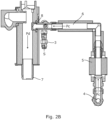
- Figures 2A and 2B show a printing fluid dispersing mechanism 1 to be used in an electrostatic printer.
- the mechanism of figures 1A and 1B comprises a printing fluid inlet 4 adapted to receive a concentrated printing fluid (Pc), e.g., an electrostatic ink from a printing fluid source and a printing fluid outlet 7 through which a dispersed printing fluid (Pd) is output.
- Pc concentrated printing fluid
- Pd dispersed printing fluid
- the mechanism 1 may be an on-line mechanism wherein a printing fluid supply is connected to the printing fluid inlet 4 and an element within a printing system is connected to the printing fluid outlet 7 thereby avoiding the use of batches and other laborious operations to be performed by the user.
- the mechanism 1 comprise a pump 5 which may be, e.g., a positive displacement pump that pumps the printing fluid though an interconnect duct 6 towards a nozzle 8, the nozzle has holes through which the concentrated printing fluid (Pc) passes and is dispersed by the holes, so that downstream the nozzle 8, a dispersed printing fluid (Pd) is obtained.
- Pumping the fluid through the nozzle 8 may generate several effects that are beneficial for the dispersing of the printing fluid. Such as increase of fluid speed or generating a shear on the printing fluid as will be explained with reference to figures 3A and 3B .
- Figures 3A and 3B show an example of a nozzle 8 that may be used in a dispersing mechanism 1 of the type of figures 2A and 2B .
- the nozzle 8 comprises a nozzle inlet 80, a nozzle outlet 81 and a plurality of holes 82 that generate a fluid passage between the nozzle inlet 80 and the nozzle outlet 81.
- the holes 82 of the nozzle 8 are dimensioned to allow the printing fluid to pass but, given that the holes have a smaller diameter than the interconnect duct 6, the speed increases as if flows via the holes due to mass conservation, therefore, the smaller the holes 82, the greater the speed.
- This effect may help, e.g., for mixing the concentrated printing fluid (Pc) with a solvent (S) that may be fed through a solvent inlet 3 to the interconnect duct 6.
- holes 82 with a diameter of around 700 microns ( ⁇ m) may be adequate to achieve this increased speed.
- the holes 82 of the nozzle 8 are dimensioned to directly break a compound, e.g., agglomerants within the concentrated printing fluid (Pc), by using a high-pressure pump and a nozzle with holes 82 of a diameter of around 300 microns ( ⁇ m) or 400 microns ( ⁇ m).
- the concentrated printing fluid (Pc) is pushed through a tight passage of a few hundred microns ( ⁇ m) in diameter, i.e., the holes 82.
- the concentrated printing fluid (Pc) is subjected to extremely high planar shear and elongation shear causing the breakdown of the agglomerants so that, downstream the nozzle 8, a dispersed printing fluid (Pd) is obtained.
- the nozzle may comprise holes 82 of different diameters or holes 82 with the same diameter in a range between 300 microns ( ⁇ m) and 700 microns ( ⁇ m).
- dispersion parameters are measured for a nozzle having eight holes with a diameter of 300 microns ( ⁇ m). The dispersion parameters obtained are shown in the table below Dispersion parameters 8 * 300 ⁇ diameter holes Tail 20 6 D(0.5) 7.6
- the dispersion obtained by forcing the fluid through holes e.g., in the range between 300-700 microns ( ⁇ m) achieves a proper dispersion while achieving a lower effect on the temperature the ink when compared, e.g., with dispersion methods including a mixer.
- the dispersing mechanism 1 may comprise an air inlet 2 downstream the nozzle 8, as shown in figures 2A , 2B , wherein the air inlet 2 is to be connected to a pressurized air source, e.g., an air pump that may be configured to issue an air burst downstream the nozzle 8 to perform an unclogging operation.
- a pressurized air source e.g., an air pump that may be configured to issue an air burst downstream the nozzle 8 to perform an unclogging operation.
- An example of manufacturing method for a nozzle 8 with a configuration as explained above is to avoid the presence of burr because it may affect the nozzle 8 and may increase the probabilities of the nozzle 8 getting clogged by the printing fluid.
- Figure 3C shows an example of nozzle 8 wherein a nozzle is manufactured by boring a through hole defining an internal passage 821 of a first diameter (d) that substantially defines the hole diameter, e.g., a 300 microns ( ⁇ m) to 700 microns ( ⁇ m) passage. Further, a couple of non-through complimentary borings 820, 822 are performed with a second diameter (D) at both ends of the passage 821 to at least, partly remove, some of the burr that may be left over from boring the passage 821.
- a first diameter e.g., a 300 microns ( ⁇ m) to 700 microns ( ⁇ m) passage.
- D second diameter
- Figure 4 shows an example of a method for performing a printing fluid dispersion that may be used on-line in a printing system.
- the dispersing of the printing fluid 40 may be performed by forcing printing fluid 41 through a hole, e.g., a hole within a nozzle and, subsequently, transferring the printing fluid from the nozzle to another element within the printing system 42 such as, for example, an intermediate tank in the case of electrostatic printing or to a printhead, in the case of inkjet printing.
- a feature that may be implemented in a dispersion method or apparatus according to the present disclosure is having the capability to implement an unclogging mechanism using the means normally present in a printing environment.
- such unclogging mechanism may be automatic or, at least, partially automatic.
- An example of unclogging mechanism is by injecting a burst of air through an air inlet 2 upstream the nozzle 8 as shown in figure 2A .
- An issue that arises is the detection of a clogging condition of the nozzle that may be used as unclogging trigger signal for the unclogging mechanism.
- a pressure detector may be coupled to the interconnect duct 6 between the pump 5 and the nozzle 8. If pressure exceeds a determined threshold, an unclogging trigger signal may be used to a controller to inject a burst of air, e.g., a 6 bar air burst that may, at least, partly unclog the nozzle 8.
- a burst of air e.g., a 6 bar air burst that may, at least, partly unclog the nozzle 8.
- a positive pressure pump may be used as pump 5 and the stroke period of the pump may be used as an indirect measurement of the pressure upstream the nozzle, i.e., between the nozzle and the pump 5 being the stroke period defined as the time to complete a full stroke.
- an unclogging trigger signal is issued to a controller that is to control the air burst injection upstream the nozzle. This operation may be performed several times until the stroke period is below the threshold.
- the air bursts are injected between stroke periods of the pump 5 so that the air burst do not interfere with the operation of the pump.
- FIG 5 several scenarios are simulated wherein: in a first scenario 31, one hole within the nozzle is unclogged; in a second scenario 31, five nozzles are unclogged; in a third scenario 33, thirteen holes within the nozzle are unclogged; and in a fourth scenario 34, thirty-two holes within the nozzle are unclogged. Also, the simulations were made on a master unit comprising master pump a printing fluid dispersing mechanism and a slave unit comprising a slave pump and a fluid dispersing mechanism for each scenario.
- the stroke periods are within a first master range M 1 for the master unit and within a first slave rage S 1 for the slave unit, in this case, the mean M 1m for the first master range M 1 is of around 1.85 sec (s) and the mean S 1m for the first slave range S 1 is of around 1.7 sec (s).
- the stroke periods are within a second master range M 2 for the master unit and within a second slave rage S 2 for the slave unit, in this case, the mean M 2m for the second master range M 2 is of around 1.45 sec (s) and the mean S 2m for the second slave range S 2 is of around 1.35 sec (s).
- the stroke periods are within a third master range M 3 for the master unit and within a third slave rage S 3 for the slave unit, in this case, the mean M 3m for the third master range M 3 is of around 1.45 sec (s) and the mean S 1m for the third slave range S 3 is of around 1.25 sec (s).
- the stroke periods are within a fourth master range M 4 for the master unit and within a fourth slave rage S 4 for the slave unit, in this case, the mean M 4m for the fourth master range M 4 is of around 1.45 sec (s) and the mean S 1m for the fourth slave range S 4 is of around 1.3 sec (s).
- the threshold measured in reference to the mean stroke period of the pump may be set to be of around 1.6 sec (s).
- the threshold may be set as a percentage of the stroke period in view of a stroke period wherein all nozzles are unclogged, e.g., a threshold may be set to determine if the stroke period of the pump have been increased by over 10% from the non-clogged condition.
- the threshold may be set as approximately 15% stroke period increase with a tolerance of ⁇ 3%.
- Figure 6 shows an example of method that may be performed by a controller to execute a dispersing operation with automatic unclogging detection and unclog operation.
- a dispersing of printing fluid is performed, e.g., by forcing the printing fluid through a hole as discussed with reference to figure 3 .
- a measuring of the pressure 51 upstream the hole (or the nozzle comprising a hole) may be performed to establish a possible clogging condition.
- a determination 52 is made of whether the measured pressure (P M ) is below a determined threshold (P TH ). If it is, the dispersing is continued and no unclogging operation is performed.
- an unclogging signal may be issued 53, e.g., by a controller associated to the pressure measurement and an unclogging operation is performed 54, e.g., a burst of air is injected upstream the nozzle.
- the pressure measurement may be performed indirectly, e.g., by measuring the stroke period of a pump thereby avoiding the incorporation of further sensors, such as a pressure sensor.
- the controller may be a combination of circuitry and executable instructions representing a control program to: receive signals such as, e.g., a signal indicative of the pressure between the nozzle and the pump; to perform operations e.g., to determine if the pressure is above a determined threshold; and to issue signals such as, e.g., the unclogging trigger signal.
- the controller may be a non-transitory machine-readable storage medium encoded with instructions executable by a processing resource of a computing device to perform methods such as those described herein.
Landscapes
- Physics & Mathematics (AREA)
- General Physics & Mathematics (AREA)
- Ink Jet (AREA)
Description
- Inkjet printers are, in general terms, controllable fluid ejection devices that propel droplets of printing fluid from a nozzle to form an image on a substrate wherein such propelling can be achieved by different technologies such as, e.g., thermal injection or piezo injection.
- On the other hand, electrostatic printers create an image on a photoconductive surface, apply a printing fluid having charged particles to the photoconductive surface, such that they selectively bind to the image, and then transferring the charged particles in the form of the image to a print substrate.
US2009/0239170A1 discloses a toner and a method for producing the toner, - Examples will now be described, by way of non-limiting example only, with reference to the accompanying drawings, in which:
-
Figure 1 shows a schematic diagram of a fluid dispersing system according to an example. -
Figures 2A and2B show a printing fluid dispersing system applied a printing fluid, e.g., an ink from an ink pale being transferred to an ink supply tank of a printing system. -
Figures 3A-3C show an example of a nozzle for dispersing a printing fluid. -
Figure 4 shows a flow diagram with an example of a printing fluid dispersing method. -
Figure 5 shows examples of stroke periods of a positive displacement pump for a nozzle in different clogging conditions. -
Figure 6 shows an example of a clogging detection and unclogging operation method. - The productivity of printing systems, e.g., inkjet printers or electrostatic printers is measured by the cost-per-page (CPP) of such systems.
- Having printing fluids that are more concentrated reduces the CPP of the printing systems but, also, having higher concentrations on the printing fluids implies having systems that allow for more shear to be able to disperse such printing fluids.
- In both inkjet and electrostatic printing fluids, the concentration of the printing fluids may be increased to have a higher productivity and, therefore, the printing fluid may comprise a high-content on solids, in particular, non-volatile solids (NVS) that are to be dispersed in order to be able to use them in a printing system and/or prevent clogging of parts within the printing system. In an example, the solids concentration of the printing fluid may be over 20% and, in a further example, the solids concentration may be over 30%.
- In an example, the dispersing of the printing fluid may be performed by batches and subsequently feeding the batches to the printer, which implies that an off-line dispersing apparatus performs such operation and wherein batches are prepared and then fed to the printing system to perform a printer operation which is a laborsome method that takes more time and is to be performed by an operator. On the other hand, the dispersing may also be performed on-line wherein the printing system comprises a concentrated printing fluid inlet and dispersing mechanism that continuously disperses the printing fluid as feeds the dispersed printing fluid to the printer.
- In a further example, the dispersing may also comprise mixing the printing fluid with a solvent.
- In essence, a printing fluid dispersing method for a printing system is described, wherein the method comprises transferring printing fluid from a supply to an element within the printing system by a pump, wherein, between the supply and the element, a nozzle is provided comprising a plurality holes so that the transferring of printing fluid comprises forcing the printing fluid through the plurality of holes of the nozzle.
- In an example, the element is an intermediate tank of the printing system. In a further example, the element is a printhead.
- Also, the method comprises determining a clogging state of the nozzle, wherein determining the clogging state of the nozzle comprises measuring a pressure between the pump and the nozzle so that if the pressure exceeds a predetermined threshold, the clogging state is determined. In an example, the pump may be a positive displacement pump and the pressure between the pump and the nozzle may be measured indirectly by determining a stroke period of the pump which is proportional to the pressure between the pump and the nozzle.
- The method may, upon receipt of an unclogging trigger signal, performing an unclogging operation, wherein the unclogging operation comprises injecting a burst of air between the pump and the nozzle, i.e., upstream the nozzle. In an example, the unclogging trigger signal may be, e.g., a periodic signal or a signal issued by a user. In a further example, the unclogging trigger signal is issued by a controller upon determining a clogging state.
- The method of
claim 1 wherein the holes have a diameter between 300 microns (µm) and 700 microns (µm). - Further, it is disclosed a printing system to be fluidly connected to a printing fluid supply, the printing apparatus comprising a fluid interconnect mechanism to be fluidly connected, on a first side to a pump associated to the printing fluid supply and, on a second side, to an element within the printing system wherein the fluid interconnect mechanism comprises a nozzle intermediate to the pump and the element, the nozzle comprising a plurality of holes with a diameter between 300 microns (µm) and 700 microns (µm).
- A clogging detector is used wherein the detector is to determine if the nozzle is clogged in view of the pressure of fluid within the fluid interconnect mechanism. The nozzle clogging detector may be to determine if the nozzle is clogged in view of a stroke period of the pump.
- Also, the fluid interconnect mechanism may comprise an unclogging port coupled to the fluid interconnect mechanism and wherein the unclogging mechanism comprises an air supply to inject an air burst through the unclogging port. For example, the unclogging mechanism may inject the air burst upon receipt of an unclogging trigger signal from a controller.
- The printing system may further comprise an outlet coupling to be connected to an element of a printing system.
-
Figure 1 shows a schematic example wherein aprinting fluid source 50, e.g., an ink tank is provided with concentrated printing fluid (Pc) that needs to be dispersed. Theprinting fluid source 50 is connected by means of aprinting fluid inlet 4 to the printingfluid dispersing system 1. - The printing fluid (Pc) is pumped by means of a
pump 5 thereby forcing the concentrated printing fluid (Pc) through anozzle 8 thereby obtaining dispersed printing fluid (Pd) that can be transferred, e.g., to anelement 70 of the printing system that may be, for example, a printhead or an intermediate storage. -
Figures 2A and2B show a printingfluid dispersing mechanism 1 to be used in an electrostatic printer. In particular, the mechanism of figures 1A and 1B comprises aprinting fluid inlet 4 adapted to receive a concentrated printing fluid (Pc), e.g., an electrostatic ink from a printing fluid source and aprinting fluid outlet 7 through which a dispersed printing fluid (Pd) is output. - The
mechanism 1 may be an on-line mechanism wherein a printing fluid supply is connected to theprinting fluid inlet 4 and an element within a printing system is connected to theprinting fluid outlet 7 thereby avoiding the use of batches and other laborious operations to be performed by the user. Themechanism 1 comprise apump 5 which may be, e.g., a positive displacement pump that pumps the printing fluid though aninterconnect duct 6 towards anozzle 8, the nozzle has holes through which the concentrated printing fluid (Pc) passes and is dispersed by the holes, so that downstream thenozzle 8, a dispersed printing fluid (Pd) is obtained. - Pumping the fluid through the
nozzle 8 may generate several effects that are beneficial for the dispersing of the printing fluid. Such as increase of fluid speed or generating a shear on the printing fluid as will be explained with reference tofigures 3A and 3B . -
Figures 3A and 3B show an example of anozzle 8 that may be used in adispersing mechanism 1 of the type offigures 2A and2B . Thenozzle 8 comprises anozzle inlet 80, anozzle outlet 81 and a plurality ofholes 82 that generate a fluid passage between thenozzle inlet 80 and thenozzle outlet 81. - In an example, the
holes 82 of thenozzle 8 are dimensioned to allow the printing fluid to pass but, given that the holes have a smaller diameter than theinterconnect duct 6, the speed increases as if flows via the holes due to mass conservation, therefore, the smaller theholes 82, the greater the speed. This effect may help, e.g., for mixing the concentrated printing fluid (Pc) with a solvent (S) that may be fed through asolvent inlet 3 to theinterconnect duct 6. In this case,holes 82 with a diameter of around 700 microns (µm) may be adequate to achieve this increased speed. - Furthermore, the increased speed of the fluid inside the
holes 82 result in shear forces that allow the dispersion effect to take place. Also, a turbulent flow may be generated upstream the nozzle and, by its very irregular structure, such turbulent flow is highly favorable to mixing. - In another example, the
holes 82 of thenozzle 8 are dimensioned to directly break a compound, e.g., agglomerants within the concentrated printing fluid (Pc), by using a high-pressure pump and a nozzle withholes 82 of a diameter of around 300 microns (µm) or 400 microns (µm). In this approach, the concentrated printing fluid (Pc) is pushed through a tight passage of a few hundred microns (µm) in diameter, i.e., theholes 82. The concentrated printing fluid (Pc) is subjected to extremely high planar shear and elongation shear causing the breakdown of the agglomerants so that, downstream thenozzle 8, a dispersed printing fluid (Pd) is obtained. - Also, the nozzle may comprise
holes 82 of different diameters orholes 82 with the same diameter in a range between 300 microns (µm) and 700 microns (µm). - In an example, dispersion parameters are measured for a nozzle having eight holes with a diameter of 300 microns (µm). The dispersion parameters obtained are shown in the table below
Dispersion parameters 8 * 300 µ diameter holes Tail 20 6 D(0.5) 7.6 - Therefore, it is considered that the dispersion obtained by forcing the fluid through holes, e.g., in the range between 300-700 microns (µm) achieves a proper dispersion while achieving a lower effect on the temperature the ink when compared, e.g., with dispersion methods including a mixer.
- Given the nature of the method wherein a fluid with some solid content is forced through a nozzle with holes of a determined diameter to achieve a dispersion, the nozzle may be susceptible to clogging. Therefore, the
dispersing mechanism 1 may comprise anair inlet 2 downstream thenozzle 8, as shown infigures 2A ,2B , wherein theair inlet 2 is to be connected to a pressurized air source, e.g., an air pump that may be configured to issue an air burst downstream thenozzle 8 to perform an unclogging operation. Such unclogging operation and clog detection will be explained in more detail with reference tofigures 5 and6 . - An example of manufacturing method for a
nozzle 8 with a configuration as explained above is to avoid the presence of burr because it may affect thenozzle 8 and may increase the probabilities of thenozzle 8 getting clogged by the printing fluid. -
Figure 3C shows an example ofnozzle 8 wherein a nozzle is manufactured by boring a through hole defining aninternal passage 821 of a first diameter (d) that substantially defines the hole diameter, e.g., a 300 microns (µm) to 700 microns (µm) passage. Further, a couple of non-throughcomplimentary borings passage 821 to at least, partly remove, some of the burr that may be left over from boring thepassage 821. -
Figure 4 shows an example of a method for performing a printing fluid dispersion that may be used on-line in a printing system. The dispersing of theprinting fluid 40 may be performed by forcingprinting fluid 41 through a hole, e.g., a hole within a nozzle and, subsequently, transferring the printing fluid from the nozzle to another element within theprinting system 42 such as, for example, an intermediate tank in the case of electrostatic printing or to a printhead, in the case of inkjet printing. - As mentioned above, a feature that may be implemented in a dispersion method or apparatus according to the present disclosure is having the capability to implement an unclogging mechanism using the means normally present in a printing environment. In particular, such unclogging mechanism may be automatic or, at least, partially automatic.
- An example of unclogging mechanism is by injecting a burst of air through an
air inlet 2 upstream thenozzle 8 as shown infigure 2A . An issue that arises is the detection of a clogging condition of the nozzle that may be used as unclogging trigger signal for the unclogging mechanism. - In an example, a pressure detector may be coupled to the
interconnect duct 6 between thepump 5 and thenozzle 8. If pressure exceeds a determined threshold, an unclogging trigger signal may be used to a controller to inject a burst of air, e.g., a 6 bar air burst that may, at least, partly unclog thenozzle 8. - In a further example, a positive pressure pump may be used as
pump 5 and the stroke period of the pump may be used as an indirect measurement of the pressure upstream the nozzle, i.e., between the nozzle and thepump 5 being the stroke period defined as the time to complete a full stroke. In this example, if the stroke period of thepump 5 is above a determined threshold, an unclogging trigger signal is issued to a controller that is to control the air burst injection upstream the nozzle. This operation may be performed several times until the stroke period is below the threshold. - In an example, the air bursts are injected between stroke periods of the
pump 5 so that the air burst do not interfere with the operation of the pump. - In
figure 5 , several scenarios are simulated wherein: in afirst scenario 31, one hole within the nozzle is unclogged; in asecond scenario 31, five nozzles are unclogged; in athird scenario 33, thirteen holes within the nozzle are unclogged; and in afourth scenario 34, thirty-two holes within the nozzle are unclogged. Also, the simulations were made on a master unit comprising master pump a printing fluid dispersing mechanism and a slave unit comprising a slave pump and a fluid dispersing mechanism for each scenario. - In the
first scenario 31, the stroke periods are within a first master range M1 for the master unit and within a first slave rage S1 for the slave unit, in this case, the mean M1m for the first master range M1 is of around 1.85 sec (s) and the mean S1m for the first slave range S1 is of around 1.7 sec (s). In thesecond scenario 32, the stroke periods are within a second master range M2 for the master unit and within a second slave rage S2 for the slave unit, in this case, the mean M2m for the second master range M2 is of around 1.45 sec (s) and the mean S2m for the second slave range S2 is of around 1.35 sec (s). In thethird scenario 33, the stroke periods are within a third master range M3 for the master unit and within a third slave rage S3 for the slave unit, in this case, the mean M3m for the third master range M3 is of around 1.45 sec (s) and the mean S1m for the third slave range S3 is of around 1.25 sec (s). In thefourth scenario 34, the stroke periods are within a fourth master range M4 for the master unit and within a fourth slave rage S4 for the slave unit, in this case, the mean M4m for the fourth master range M4 is of around 1.45 sec (s) and the mean S1m for the fourth slave range S4 is of around 1.3 sec (s). - Therefore, in the example of
figure 5 , the threshold measured in reference to the mean stroke period of the pump may be set to be of around 1.6 sec (s). In a further example, the threshold may be set as a percentage of the stroke period in view of a stroke period wherein all nozzles are unclogged, e.g., a threshold may be set to determine if the stroke period of the pump have been increased by over 10% from the non-clogged condition. In a further example, the threshold may be set as approximately 15% stroke period increase with a tolerance of ±3%. -
Figure 6 shows an example of method that may be performed by a controller to execute a dispersing operation with automatic unclogging detection and unclog operation. In the example offigure 6 , a dispersing of printing fluid is performed, e.g., by forcing the printing fluid through a hole as discussed with reference tofigure 3 . Subsequently, a measuring of thepressure 51 upstream the hole (or the nozzle comprising a hole) may be performed to establish a possible clogging condition. Adetermination 52 is made of whether the measured pressure (PM) is below a determined threshold (PTH). If it is, the dispersing is continued and no unclogging operation is performed. - If the measured pressure (PM) is above the threshold (PTH), this means that the nozzle may be, at least, partially clogged so an unclogging operation may be desirable. Therefore, an unclogging signal may be issued 53, e.g., by a controller associated to the pressure measurement and an unclogging operation is performed 54, e.g., a burst of air is injected upstream the nozzle.
- In an example, the pressure measurement may be performed indirectly, e.g., by measuring the stroke period of a pump thereby avoiding the incorporation of further sensors, such as a pressure sensor.
- Furthermore, the controller may be a combination of circuitry and executable instructions representing a control program to: receive signals such as, e.g., a signal indicative of the pressure between the nozzle and the pump; to perform operations e.g., to determine if the pressure is above a determined threshold; and to issue signals such as, e.g., the unclogging trigger signal. In general, the controller may be a non-transitory machine-readable storage medium encoded with instructions executable by a processing resource of a computing device to perform methods such as those described herein.
Claims (13)
- A printing fluid dispersing method for a printing system, the method comprising transferring (41) printing fluid from a supply to an element within the printing system by a pump (5), wherein, between the supply and the element, a nozzle (8) is provided comprising a plurality holes (82) so that the transferring of printing fluid comprises forcing (41), by the pump, the printing fluid through the plurality of holes of the nozzle, characterized by the method further comprising determining a clogging state of the nozzle, wherein determining the clogging state of the nozzle comprises measuring (51) a pressure between the pump and the nozzle so that if the pressure exceeds (52) a predetermined threshold, the clogging state is determined.
- The method of claim 1, wherein the element is an intermediate tank of the printing system.
- The method of claim 1, wherein the element is a printhead.
- The method of claim 1 wherein the pump is a positive displacement pump and the pressure between the pump and the nozzle is measured indirectly by determining a stroke period of the pump which is proportional to the pressure between the pump and the nozzle.
- The method of claim 1 further comprising: upon receipt of an unclogging trigger signal (53), performing an unclogging operation (54), wherein the unclogging operation comprises injecting a burst of air between the pump and the nozzle.
- The method of claim 5 wherein the unclogging trigger signal is a periodic signal or a signal issued by a user.
- The method of claim 5 wherein the unclogging trigger signal is issued by a controller upon determining a clogging state.
- The method of claim 1 wherein the holes have a diameter between 300 microns (µm) and 700 microns (µm).
- A printing system configured to be fluidly connected to a printing fluid supply, the printing system comprising a fluid interconnect mechanism configured to be fluidly connected, on a first side to a pump (5) associated to the printing fluid supply and, on a second side, to an element within the printing system wherein the fluid interconnect mechanism comprises a nozzle (8) intermediate to the pump and the element, the nozzle comprising a plurality of holes with a diameter between 300 microns (µm) and 700 microns (µm),
characterized by the system comprising a nozzle clogging detector wherein the detector is configured to determine if the nozzle is clogged in view of the pressure of fluid within the fluid interconnect mechanism, the printing system further comprising a controller configured to execute a dispersing operation according to any of the above method claims. - The system of claim 9, wherein the detector is configured to determine if the nozzle is clogged in view of a stroke period of the pump.
- The system of claim 9 further comprising an unclogging mechanism wherein the fluid interconnect mechanism comprises an unclogging port coupled to the fluid interconnect mechanism and wherein the unclogging mechanism comprises an air supply configured to inject an air burst through the unclogging port.
- The system of claim 11 wherein the unclogging mechanism is configured to inject the air burst upon receipt of an unclogging trigger signal from a controller.
- The system of claim 9 further comprising:
an outlet coupling configured to be connected to the element of the printing system
Applications Claiming Priority (1)
| Application Number | Priority Date | Filing Date | Title |
|---|---|---|---|
| PCT/US2018/030054 WO2019209350A1 (en) | 2018-04-28 | 2018-04-28 | Dispersing concentrated printing fluids |
Publications (3)
| Publication Number | Publication Date |
|---|---|
| EP3787902A1 EP3787902A1 (en) | 2021-03-10 |
| EP3787902A4 EP3787902A4 (en) | 2021-12-01 |
| EP3787902B1 true EP3787902B1 (en) | 2023-07-05 |
Family
ID=68294217
Family Applications (1)
| Application Number | Title | Priority Date | Filing Date |
|---|---|---|---|
| EP18916101.1A Active EP3787902B1 (en) | 2018-04-28 | 2018-04-28 | Dispersing concentrated printing fluids |
Country Status (3)
| Country | Link |
|---|---|
| US (1) | US11872819B2 (en) |
| EP (1) | EP3787902B1 (en) |
| WO (1) | WO2019209350A1 (en) |
Family Cites Families (18)
| Publication number | Priority date | Publication date | Assignee | Title |
|---|---|---|---|---|
| US2904267A (en) * | 1957-09-16 | 1959-09-15 | Georgia Kaolin Co | Method of treating kaolinitic clay |
| JPH01176475A (en) | 1987-12-28 | 1989-07-12 | Tamura Seisakusho Co Ltd | Nozzle clogging detection |
| US5296137A (en) * | 1992-03-12 | 1994-03-22 | Oil-Dri Corporation Of America | Filtration system with axial flow cartridge |
| KR0132809B1 (en) | 1995-03-14 | 1998-04-14 | 김광호 | How to Adjust Ink Suction Volume in Ink-Jet Printers |
| US5942095A (en) * | 1996-10-07 | 1999-08-24 | Phoenix Precision Graphics, Inc. | Method of continuous purification of liquid toner in an electrostatic printing system |
| KR100234433B1 (en) | 1997-11-04 | 1999-12-15 | 윤종용 | Nozzle blockage detection device and method |
| JP2000255056A (en) | 1999-03-10 | 2000-09-19 | Seiko Epson Corp | Control method of inkjet recording apparatus |
| US7135265B2 (en) * | 2002-06-10 | 2006-11-14 | Seiko Epson Corporation | Production method of toner, toner, and toner producing apparatus |
| EP1737332B2 (en) * | 2004-03-16 | 2020-06-10 | Arçelik Anonim Sirketi | A dishwasher and control method thereof |
| JP5365904B2 (en) | 2008-03-17 | 2013-12-11 | 株式会社リコー | Toner production method |
| JP2010228149A (en) * | 2009-03-26 | 2010-10-14 | Seiko Epson Corp | Fluid supply device, fluid ejection device, and fluid supply method |
| SG182339A1 (en) * | 2010-01-08 | 2012-08-30 | Parkson Corp | Apparatus for treating liquid containing impurities |
| US8797373B2 (en) * | 2010-03-18 | 2014-08-05 | Ricoh Company, Ltd. | Liquid droplet ejecting method, liquid droplet ejection apparatus, inkjet recording apparatus, production method of fine particles, fine particle production apparatus, and toner |
| US8474930B2 (en) | 2010-08-30 | 2013-07-02 | Donald O. Rasmussen | Inkjet printer ink delivery system |
| JP2014115611A (en) * | 2012-11-15 | 2014-06-26 | Ricoh Co Ltd | Developer conveyance apparatus and image forming apparatus |
| JP6421573B2 (en) * | 2014-12-11 | 2018-11-14 | セイコーエプソン株式会社 | Droplet discharge device |
| ITUB20153006A1 (en) | 2015-08-07 | 2017-02-07 | System Spa | Control method for detecting the operating status of the nozzles of an ink jet printhead. |
| EP3479956A1 (en) * | 2017-11-07 | 2019-05-08 | Satisloh AG | Method for manufacturing optical elements according to a prescription |
-
2018
- 2018-04-28 WO PCT/US2018/030054 patent/WO2019209350A1/en not_active Ceased
- 2018-04-28 EP EP18916101.1A patent/EP3787902B1/en active Active
- 2018-04-28 US US16/605,934 patent/US11872819B2/en active Active
Also Published As
| Publication number | Publication date |
|---|---|
| EP3787902A1 (en) | 2021-03-10 |
| EP3787902A4 (en) | 2021-12-01 |
| US20210362504A1 (en) | 2021-11-25 |
| US11872819B2 (en) | 2024-01-16 |
| WO2019209350A1 (en) | 2019-10-31 |
Similar Documents
| Publication | Publication Date | Title |
|---|---|---|
| US8500256B2 (en) | Inkjet head device and method of controlling inkjet head | |
| EP2769847A2 (en) | Ink supply system for ink jet printers | |
| US11351789B2 (en) | Fluid ejection device with nozzle column data groups including drive bubble detect data | |
| US20190105897A1 (en) | Print head having ink pressure sensor | |
| CN102642402A (en) | Liquid ejecting apparatus | |
| EP1744895B2 (en) | Imaging apparatus and methods for homogenizing ink | |
| US9649848B1 (en) | Ink recirculation for Drop-On-Demand ink jet systems | |
| US11872819B2 (en) | Dispersing concentrated printing fluids | |
| DE102013110771A1 (en) | Arrangement for supplying a print head unit having at least one print head with ink in an ink printing device | |
| CA2669574C (en) | Constant flow high pressure printing system | |
| US10518551B1 (en) | System and method for attenuating the drying of ink from a printhead | |
| US20210107279A1 (en) | Zonal actuator fault detection | |
| DE102013110799A1 (en) | Arrangement for supplying a print head unit having at least one print head with ink in an ink printing device | |
| US8899733B2 (en) | Method for supplying at least one print head with ink in an inkjet printer | |
| US9573381B2 (en) | Printing apparatus and bubble exhaust method therefor | |
| US8517504B2 (en) | Print head hydration system | |
| US9475305B2 (en) | Liquid supply apparatus and liquid ejection apparatus with contactless detection of liquid remaining amount | |
| JP7335141B2 (en) | Systems and methods for reducing drying of ink from printheads during idle periods | |
| EP3756894B1 (en) | Method for operating an ink printing machine | |
| DE102015104584B4 (en) | Arrangement and method for degassing ink for a print head unit in an ink printing device | |
| US12491720B2 (en) | Monitoring printing fluids | |
| KR102019833B1 (en) | Identifying primed printheads | |
| US20260109152A1 (en) | Printhead system with nozzle rejuvenation system | |
| US11590762B2 (en) | Recirculations using two pumps | |
| US11292250B2 (en) | Non-nucleation fluid actuator measurements |
Legal Events
| Date | Code | Title | Description |
|---|---|---|---|
| STAA | Information on the status of an ep patent application or granted ep patent |
Free format text: STATUS: THE INTERNATIONAL PUBLICATION HAS BEEN MADE |
|
| PUAI | Public reference made under article 153(3) epc to a published international application that has entered the european phase |
Free format text: ORIGINAL CODE: 0009012 |
|
| STAA | Information on the status of an ep patent application or granted ep patent |
Free format text: STATUS: REQUEST FOR EXAMINATION WAS MADE |
|
| 17P | Request for examination filed |
Effective date: 20201016 |
|
| AK | Designated contracting states |
Kind code of ref document: A1 Designated state(s): AL AT BE BG CH CY CZ DE DK EE ES FI FR GB GR HR HU IE IS IT LI LT LU LV MC MK MT NL NO PL PT RO RS SE SI SK SM TR |
|
| AX | Request for extension of the european patent |
Extension state: BA ME |
|
| DAV | Request for validation of the european patent (deleted) | ||
| DAX | Request for extension of the european patent (deleted) | ||
| A4 | Supplementary search report drawn up and despatched |
Effective date: 20211102 |
|
| RIC1 | Information provided on ipc code assigned before grant |
Ipc: G03G 15/10 20060101ALI20211026BHEP Ipc: B41J 2/165 20060101ALI20211026BHEP Ipc: B41J 2/175 20060101AFI20211026BHEP |
|
| STAA | Information on the status of an ep patent application or granted ep patent |
Free format text: STATUS: EXAMINATION IS IN PROGRESS |
|
| 17Q | First examination report despatched |
Effective date: 20221004 |
|
| GRAP | Despatch of communication of intention to grant a patent |
Free format text: ORIGINAL CODE: EPIDOSNIGR1 |
|
| STAA | Information on the status of an ep patent application or granted ep patent |
Free format text: STATUS: GRANT OF PATENT IS INTENDED |
|
| INTG | Intention to grant announced |
Effective date: 20230412 |
|
| GRAS | Grant fee paid |
Free format text: ORIGINAL CODE: EPIDOSNIGR3 |
|
| GRAA | (expected) grant |
Free format text: ORIGINAL CODE: 0009210 |
|
| STAA | Information on the status of an ep patent application or granted ep patent |
Free format text: STATUS: THE PATENT HAS BEEN GRANTED |
|
| AK | Designated contracting states |
Kind code of ref document: B1 Designated state(s): AL AT BE BG CH CY CZ DE DK EE ES FI FR GB GR HR HU IE IS IT LI LT LU LV MC MK MT NL NO PL PT RO RS SE SI SK SM TR |
|
| REG | Reference to a national code |
Ref country code: CH Ref legal event code: EP |
|
| REG | Reference to a national code |
Ref country code: AT Ref legal event code: REF Ref document number: 1584506 Country of ref document: AT Kind code of ref document: T Effective date: 20230715 |
|
| REG | Reference to a national code |
Ref country code: DE Ref legal event code: R096 Ref document number: 602018053049 Country of ref document: DE |
|
| REG | Reference to a national code |
Ref country code: IE Ref legal event code: FG4D |
|
| REG | Reference to a national code |
Ref country code: LT Ref legal event code: MG9D |
|
| REG | Reference to a national code |
Ref country code: NL Ref legal event code: MP Effective date: 20230705 |
|
| REG | Reference to a national code |
Ref country code: AT Ref legal event code: MK05 Ref document number: 1584506 Country of ref document: AT Kind code of ref document: T Effective date: 20230705 |
|
| PG25 | Lapsed in a contracting state [announced via postgrant information from national office to epo] |
Ref country code: NL Free format text: LAPSE BECAUSE OF FAILURE TO SUBMIT A TRANSLATION OF THE DESCRIPTION OR TO PAY THE FEE WITHIN THE PRESCRIBED TIME-LIMIT Effective date: 20230705 |
|
| PG25 | Lapsed in a contracting state [announced via postgrant information from national office to epo] |
Ref country code: GR Free format text: LAPSE BECAUSE OF FAILURE TO SUBMIT A TRANSLATION OF THE DESCRIPTION OR TO PAY THE FEE WITHIN THE PRESCRIBED TIME-LIMIT Effective date: 20231006 |
|
| PG25 | Lapsed in a contracting state [announced via postgrant information from national office to epo] |
Ref country code: ES Free format text: LAPSE BECAUSE OF FAILURE TO SUBMIT A TRANSLATION OF THE DESCRIPTION OR TO PAY THE FEE WITHIN THE PRESCRIBED TIME-LIMIT Effective date: 20230705 |
|
| PG25 | Lapsed in a contracting state [announced via postgrant information from national office to epo] |
Ref country code: IS Free format text: LAPSE BECAUSE OF FAILURE TO SUBMIT A TRANSLATION OF THE DESCRIPTION OR TO PAY THE FEE WITHIN THE PRESCRIBED TIME-LIMIT Effective date: 20231105 |
|
| PG25 | Lapsed in a contracting state [announced via postgrant information from national office to epo] |
Ref country code: SE Free format text: LAPSE BECAUSE OF FAILURE TO SUBMIT A TRANSLATION OF THE DESCRIPTION OR TO PAY THE FEE WITHIN THE PRESCRIBED TIME-LIMIT Effective date: 20230705 Ref country code: RS Free format text: LAPSE BECAUSE OF FAILURE TO SUBMIT A TRANSLATION OF THE DESCRIPTION OR TO PAY THE FEE WITHIN THE PRESCRIBED TIME-LIMIT Effective date: 20230705 Ref country code: PT Free format text: LAPSE BECAUSE OF FAILURE TO SUBMIT A TRANSLATION OF THE DESCRIPTION OR TO PAY THE FEE WITHIN THE PRESCRIBED TIME-LIMIT Effective date: 20231106 Ref country code: NO Free format text: LAPSE BECAUSE OF FAILURE TO SUBMIT A TRANSLATION OF THE DESCRIPTION OR TO PAY THE FEE WITHIN THE PRESCRIBED TIME-LIMIT Effective date: 20231005 Ref country code: LV Free format text: LAPSE BECAUSE OF FAILURE TO SUBMIT A TRANSLATION OF THE DESCRIPTION OR TO PAY THE FEE WITHIN THE PRESCRIBED TIME-LIMIT Effective date: 20230705 Ref country code: LT Free format text: LAPSE BECAUSE OF FAILURE TO SUBMIT A TRANSLATION OF THE DESCRIPTION OR TO PAY THE FEE WITHIN THE PRESCRIBED TIME-LIMIT Effective date: 20230705 Ref country code: IS Free format text: LAPSE BECAUSE OF FAILURE TO SUBMIT A TRANSLATION OF THE DESCRIPTION OR TO PAY THE FEE WITHIN THE PRESCRIBED TIME-LIMIT Effective date: 20231105 Ref country code: HR Free format text: LAPSE BECAUSE OF FAILURE TO SUBMIT A TRANSLATION OF THE DESCRIPTION OR TO PAY THE FEE WITHIN THE PRESCRIBED TIME-LIMIT Effective date: 20230705 Ref country code: GR Free format text: LAPSE BECAUSE OF FAILURE TO SUBMIT A TRANSLATION OF THE DESCRIPTION OR TO PAY THE FEE WITHIN THE PRESCRIBED TIME-LIMIT Effective date: 20231006 Ref country code: FI Free format text: LAPSE BECAUSE OF FAILURE TO SUBMIT A TRANSLATION OF THE DESCRIPTION OR TO PAY THE FEE WITHIN THE PRESCRIBED TIME-LIMIT Effective date: 20230705 Ref country code: ES Free format text: LAPSE BECAUSE OF FAILURE TO SUBMIT A TRANSLATION OF THE DESCRIPTION OR TO PAY THE FEE WITHIN THE PRESCRIBED TIME-LIMIT Effective date: 20230705 Ref country code: AT Free format text: LAPSE BECAUSE OF FAILURE TO SUBMIT A TRANSLATION OF THE DESCRIPTION OR TO PAY THE FEE WITHIN THE PRESCRIBED TIME-LIMIT Effective date: 20230705 |
|
| PG25 | Lapsed in a contracting state [announced via postgrant information from national office to epo] |
Ref country code: PL Free format text: LAPSE BECAUSE OF FAILURE TO SUBMIT A TRANSLATION OF THE DESCRIPTION OR TO PAY THE FEE WITHIN THE PRESCRIBED TIME-LIMIT Effective date: 20230705 |
|
| REG | Reference to a national code |
Ref country code: DE Ref legal event code: R097 Ref document number: 602018053049 Country of ref document: DE |
|
| PG25 | Lapsed in a contracting state [announced via postgrant information from national office to epo] |
Ref country code: SM Free format text: LAPSE BECAUSE OF FAILURE TO SUBMIT A TRANSLATION OF THE DESCRIPTION OR TO PAY THE FEE WITHIN THE PRESCRIBED TIME-LIMIT Effective date: 20230705 Ref country code: RO Free format text: LAPSE BECAUSE OF FAILURE TO SUBMIT A TRANSLATION OF THE DESCRIPTION OR TO PAY THE FEE WITHIN THE PRESCRIBED TIME-LIMIT Effective date: 20230705 Ref country code: EE Free format text: LAPSE BECAUSE OF FAILURE TO SUBMIT A TRANSLATION OF THE DESCRIPTION OR TO PAY THE FEE WITHIN THE PRESCRIBED TIME-LIMIT Effective date: 20230705 Ref country code: DK Free format text: LAPSE BECAUSE OF FAILURE TO SUBMIT A TRANSLATION OF THE DESCRIPTION OR TO PAY THE FEE WITHIN THE PRESCRIBED TIME-LIMIT Effective date: 20230705 Ref country code: CZ Free format text: LAPSE BECAUSE OF FAILURE TO SUBMIT A TRANSLATION OF THE DESCRIPTION OR TO PAY THE FEE WITHIN THE PRESCRIBED TIME-LIMIT Effective date: 20230705 Ref country code: SK Free format text: LAPSE BECAUSE OF FAILURE TO SUBMIT A TRANSLATION OF THE DESCRIPTION OR TO PAY THE FEE WITHIN THE PRESCRIBED TIME-LIMIT Effective date: 20230705 |
|
| PLBE | No opposition filed within time limit |
Free format text: ORIGINAL CODE: 0009261 |
|
| STAA | Information on the status of an ep patent application or granted ep patent |
Free format text: STATUS: NO OPPOSITION FILED WITHIN TIME LIMIT |
|
| PG25 | Lapsed in a contracting state [announced via postgrant information from national office to epo] |
Ref country code: IT Free format text: LAPSE BECAUSE OF FAILURE TO SUBMIT A TRANSLATION OF THE DESCRIPTION OR TO PAY THE FEE WITHIN THE PRESCRIBED TIME-LIMIT Effective date: 20230705 |
|
| 26N | No opposition filed |
Effective date: 20240408 |
|
| PG25 | Lapsed in a contracting state [announced via postgrant information from national office to epo] |
Ref country code: SI Free format text: LAPSE BECAUSE OF FAILURE TO SUBMIT A TRANSLATION OF THE DESCRIPTION OR TO PAY THE FEE WITHIN THE PRESCRIBED TIME-LIMIT Effective date: 20230705 |
|
| PG25 | Lapsed in a contracting state [announced via postgrant information from national office to epo] |
Ref country code: BG Free format text: LAPSE BECAUSE OF FAILURE TO SUBMIT A TRANSLATION OF THE DESCRIPTION OR TO PAY THE FEE WITHIN THE PRESCRIBED TIME-LIMIT Effective date: 20230705 |
|
| PG25 | Lapsed in a contracting state [announced via postgrant information from national office to epo] |
Ref country code: MC Free format text: LAPSE BECAUSE OF FAILURE TO SUBMIT A TRANSLATION OF THE DESCRIPTION OR TO PAY THE FEE WITHIN THE PRESCRIBED TIME-LIMIT Effective date: 20230705 |
|
| PG25 | Lapsed in a contracting state [announced via postgrant information from national office to epo] |
Ref country code: MC Free format text: LAPSE BECAUSE OF FAILURE TO SUBMIT A TRANSLATION OF THE DESCRIPTION OR TO PAY THE FEE WITHIN THE PRESCRIBED TIME-LIMIT Effective date: 20230705 Ref country code: BG Free format text: LAPSE BECAUSE OF FAILURE TO SUBMIT A TRANSLATION OF THE DESCRIPTION OR TO PAY THE FEE WITHIN THE PRESCRIBED TIME-LIMIT Effective date: 20230705 |
|
| REG | Reference to a national code |
Ref country code: CH Ref legal event code: PL |
|
| PG25 | Lapsed in a contracting state [announced via postgrant information from national office to epo] |
Ref country code: LU Free format text: LAPSE BECAUSE OF NON-PAYMENT OF DUE FEES Effective date: 20240428 |
|
| GBPC | Gb: european patent ceased through non-payment of renewal fee |
Effective date: 20240428 |
|
| REG | Reference to a national code |
Ref country code: BE Ref legal event code: MM Effective date: 20240430 |
|
| PG25 | Lapsed in a contracting state [announced via postgrant information from national office to epo] |
Ref country code: LU Free format text: LAPSE BECAUSE OF NON-PAYMENT OF DUE FEES Effective date: 20240428 |
|
| PG25 | Lapsed in a contracting state [announced via postgrant information from national office to epo] |
Ref country code: BE Free format text: LAPSE BECAUSE OF NON-PAYMENT OF DUE FEES Effective date: 20240430 |
|
| PG25 | Lapsed in a contracting state [announced via postgrant information from national office to epo] |
Ref country code: GB Free format text: LAPSE BECAUSE OF NON-PAYMENT OF DUE FEES Effective date: 20240428 |
|
| PG25 | Lapsed in a contracting state [announced via postgrant information from national office to epo] |
Ref country code: FR Free format text: LAPSE BECAUSE OF NON-PAYMENT OF DUE FEES Effective date: 20240430 |
|
| PG25 | Lapsed in a contracting state [announced via postgrant information from national office to epo] |
Ref country code: GB Free format text: LAPSE BECAUSE OF NON-PAYMENT OF DUE FEES Effective date: 20240428 Ref country code: FR Free format text: LAPSE BECAUSE OF NON-PAYMENT OF DUE FEES Effective date: 20240430 Ref country code: BE Free format text: LAPSE BECAUSE OF NON-PAYMENT OF DUE FEES Effective date: 20240430 Ref country code: CH Free format text: LAPSE BECAUSE OF NON-PAYMENT OF DUE FEES Effective date: 20240430 |
|
| PG25 | Lapsed in a contracting state [announced via postgrant information from national office to epo] |
Ref country code: IE Free format text: LAPSE BECAUSE OF NON-PAYMENT OF DUE FEES Effective date: 20240428 |
|
| PGFP | Annual fee paid to national office [announced via postgrant information from national office to epo] |
Ref country code: DE Payment date: 20250319 Year of fee payment: 8 |
|
| PG25 | Lapsed in a contracting state [announced via postgrant information from national office to epo] |
Ref country code: CY Free format text: LAPSE BECAUSE OF FAILURE TO SUBMIT A TRANSLATION OF THE DESCRIPTION OR TO PAY THE FEE WITHIN THE PRESCRIBED TIME-LIMIT; INVALID AB INITIO Effective date: 20180428 |
|
| PG25 | Lapsed in a contracting state [announced via postgrant information from national office to epo] |
Ref country code: HU Free format text: LAPSE BECAUSE OF FAILURE TO SUBMIT A TRANSLATION OF THE DESCRIPTION OR TO PAY THE FEE WITHIN THE PRESCRIBED TIME-LIMIT; INVALID AB INITIO Effective date: 20180428 |