EP3787375B1 - Adapter zum elektrischen verbinden einer beleuchtungsvorrichtung mit einer elektrischen schiene - Google Patents
Adapter zum elektrischen verbinden einer beleuchtungsvorrichtung mit einer elektrischen schiene Download PDFInfo
- Publication number
- EP3787375B1 EP3787375B1 EP19194588.0A EP19194588A EP3787375B1 EP 3787375 B1 EP3787375 B1 EP 3787375B1 EP 19194588 A EP19194588 A EP 19194588A EP 3787375 B1 EP3787375 B1 EP 3787375B1
- Authority
- EP
- European Patent Office
- Prior art keywords
- adaptor
- electrified track
- control unit
- track
- interface
- Prior art date
- Legal status (The legal status is an assumption and is not a legal conclusion. Google has not performed a legal analysis and makes no representation as to the accuracy of the status listed.)
- Active
Links
Images


Classifications
-
- F—MECHANICAL ENGINEERING; LIGHTING; HEATING; WEAPONS; BLASTING
- F21—LIGHTING
- F21V—FUNCTIONAL FEATURES OR DETAILS OF LIGHTING DEVICES OR SYSTEMS THEREOF; STRUCTURAL COMBINATIONS OF LIGHTING DEVICES WITH OTHER ARTICLES, NOT OTHERWISE PROVIDED FOR
- F21V23/00—Arrangement of electric circuit elements in or on lighting devices
- F21V23/06—Arrangement of electric circuit elements in or on lighting devices the elements being coupling devices, e.g. connectors
-
- H—ELECTRICITY
- H02—GENERATION; CONVERSION OR DISTRIBUTION OF ELECTRIC POWER
- H02J—CIRCUIT ARRANGEMENTS OR SYSTEMS FOR SUPPLYING OR DISTRIBUTING ELECTRIC POWER; SYSTEMS FOR STORING ELECTRIC ENERGY
- H02J3/00—Circuit arrangements for AC mains or AC distribution networks
- H02J3/007—Arrangements for selectively connecting the load or loads to one or several among a plurality of power lines or power sources
-
- F—MECHANICAL ENGINEERING; LIGHTING; HEATING; WEAPONS; BLASTING
- F21—LIGHTING
- F21V—FUNCTIONAL FEATURES OR DETAILS OF LIGHTING DEVICES OR SYSTEMS THEREOF; STRUCTURAL COMBINATIONS OF LIGHTING DEVICES WITH OTHER ARTICLES, NOT OTHERWISE PROVIDED FOR
- F21V23/00—Arrangement of electric circuit elements in or on lighting devices
-
- H—ELECTRICITY
- H01—ELECTRIC ELEMENTS
- H01R—ELECTRICALLY-CONDUCTIVE CONNECTIONS; STRUCTURAL ASSOCIATIONS OF A PLURALITY OF MUTUALLY-INSULATED ELECTRICAL CONNECTING ELEMENTS; COUPLING DEVICES; CURRENT COLLECTORS
- H01R13/00—Details of coupling devices of the kinds covered by groups H01R12/70 or H01R24/00 - H01R33/00
- H01R13/66—Structural association with built-in electrical component
- H01R13/665—Structural association with built-in electrical component with built-in electronic circuit
-
- H—ELECTRICITY
- H02—GENERATION; CONVERSION OR DISTRIBUTION OF ELECTRIC POWER
- H02J—CIRCUIT ARRANGEMENTS OR SYSTEMS FOR SUPPLYING OR DISTRIBUTING ELECTRIC POWER; SYSTEMS FOR STORING ELECTRIC ENERGY
- H02J9/00—Circuit arrangements for emergency or stand-by power supply, e.g. for emergency lighting
- H02J9/04—Circuit arrangements for emergency or stand-by power supply, e.g. for emergency lighting in which the distribution system is disconnected from the normal source and connected to a standby source
- H02J9/06—Circuit arrangements for emergency or stand-by power supply, e.g. for emergency lighting in which the distribution system is disconnected from the normal source and connected to a standby source with automatic change-over, e.g. UPS systems
- H02J9/062—Circuit arrangements for emergency or stand-by power supply, e.g. for emergency lighting in which the distribution system is disconnected from the normal source and connected to a standby source with automatic change-over, e.g. UPS systems for AC powered loads
- H02J9/065—Circuit arrangements for emergency or stand-by power supply, e.g. for emergency lighting in which the distribution system is disconnected from the normal source and connected to a standby source with automatic change-over, e.g. UPS systems for AC powered loads for lighting purposes
-
- H—ELECTRICITY
- H05—ELECTRIC TECHNIQUES NOT OTHERWISE PROVIDED FOR
- H05B—ELECTRIC HEATING; ELECTRIC LIGHT SOURCES NOT OTHERWISE PROVIDED FOR; CIRCUIT ARRANGEMENTS FOR ELECTRIC LIGHT SOURCES, IN GENERAL
- H05B47/00—Circuit arrangements for operating light sources in general, i.e. where the type of light source is not relevant
Definitions
- the invention relates to an adaptor for electrically connecting a lighting apparatus to an electrified track.
- the invention further relates to a system comprising an electrified track and an adaptor.
- EP3217090A1 proposes a lighting system comprising an electrical track having three mains phases and an adapter for electrically connecting a lighting device to the electrical track, such that the lighting device may receive power from the mains.
- the adapter supports the lighting device, for example a spotlight.
- the electrical track may hold several adapters, hence several lighting devices, which are for example arranged in a row.
- the adapter includes a mechanism configured for extracting contacts automatically when the adapter is fitted in the electrical track, such that the contacts are electrically connected to the three mains phases.
- the known adapter presents some drawbacks and limitations.
- the automatic connection of the contacts to the three mains phases limits the flexibility in the electrical connection possibilities.
- EP 0 486 714 A1 discloses a light band, wherein for an easy and fast assembly of light bands the required feed-through wiring on the side of the carrier rail can be designed as a conductor rail.
- DE 10 2012 208 297 A1 discloses a current supply arrangement with phase selection for a luminaire.
- an adaptor for electrically connecting a lighting apparatus to an electrified track comprises AC main phases L1, L2 and L3 and a neutral wire N
- the adaptor has a housing designed to be inserted into a U-shaped profile of the electrified track
- the adaptor has contacts for contacting the AC main phases L1, L2 and L3 and the neutral wire N of the electrified track
- the adaptor comprises an electronic control unit in the housing, and the control unit is configured to select a combination of one of the all contacted AC main phases L1, L2, L3 with the neutral wire N for supplying the lighting apparatus.
- the control unit is configured to detect an insertion orientation of the adaptor by sensing an AC-voltage present at the different phases L1, L2, L3 and N.
- the adaptor comprises terminals in order to supply the lighting apparatus, such as an LED module.
- control unit is configured to contact one of the possible combinations L1/N, L2/N and L3/N.
- the electrical phase selection switch can respond to a power failure of one phase and automatically switch to another phase non-affected by power failure.
- the adaptor is configured to be inserted into the electrified track in two different orientations.
- the two different orientations are rotated by 180 degrees.
- the electrified track has a cross-sectional shape of U.
- the adaptor comprises LED-driver electronics and is configured to be inserted preferably flush with the U-shaped profile of the electrified track.
- control unit is configured to selectively contact a combination of one of L1, L2, L3 with N electronically inside the adaptor to output terminals, wherein the output terminals are fed to an AC input of the LED-driver electronics.
- the adaptor further comprises a selection network for selecting the L1, L2, L2 and N wire, wherein the selection network comprises a plurality of controllable high voltage semi-conductor switches, such as triacs or high voltage transistors.
- control unit is further configured to select L1, L2, L2 and N wire based on a rectifying diode network.
- the adaptor further comprises mechanical measures integrated in the housing such that the adaptor can only be inserted in one predetermined orientation in the electrified track.
- control unit is connected with an interface.
- the interface is a wireless interface such as an NFC interface or a wired interface such as a DALI bus interface.
- phase has no longer to be set manually, but can also be adjusted, for example via DALI bus interface.
- the interface comprises mechanical means on the adaptor itself.
- the invention also relates to a system comprising an electrified track comprising AC main phases L1, L2 and L3 and a neutral wire N, and an adaptor according to the first aspect or any one of the implementation forms thereof.
- the aspect of the present invention might contain integrated circuits that are readily manufacturable using conventional semiconductor technologies, such as complementary metal-oxide semiconductor technology, short "CMOS".
- CMOS complementary metal-oxide semiconductor technology
- the aspects of the present invention may be implemented with other manufacturing processes for making optical as well as electrical devices.
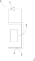
- Fig. 1 shows a system 100 comprising an adaptor 103 for electrically connecting a lighting apparatus 101 to an electrified track 102 according to an embodiment.
- the electrified track 102 comprises AC main phases L1, L2 and L3 and a neutral wire N.
- the adaptor 103 has a housing designed to be inserted into a U-shaped profile of the electrified track 102, wherein the adaptor 103 has contacts for contacting the AC main phases L1, L2 and L3 and the neutral wire N of the electrified track 102.
- the adaptor 103 comprises an electronic control unit 103a in the housing, wherein the control unit 103a is configured to select a combination of one of the all connected AC main phases L1, L2, L3 with the neutral wire N for supplying the lighting apparatus 101.
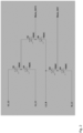
- Fig. 2 shows a selection network for an adaptor 103 for electrically connecting a lighting apparatus 101 to the electrified track 102 according to an embodiment.
- a situation is shown in which the adapter 103 can be inserted into the electrified track 102 in two different orientations (rotated by 180 degree), such that, depending on the insertion orientation of the adapter 103, different contacts can actually be contacted to the contacts of the adapter 103.
- a low-power voltage supply is provided such that already in this state (in which no phase is connected to the output), a control circuitry or electronic control unit 103a, such as for example a micro-controller of the driver is powered.
- the control circuitry 103a detects the insertion orientation of the adapter by sensing at which contacts actually voltage is present.
- control circuitry 103a is supplied in a wireless or in a wired manner with the instructions as which of the L1, L2 and L3 shall be switched active in combination with the N wire.
- a selection network which comprises a plurality of controllable high voltage semi-conductor switches, such as triacs U1, U2, U3, U4, U5 and U6 or high voltage transistors.
- control circuitry or electronic control unit 103a controls the semi-conductor switches such that the desired phase L1, L2, L3 is switched active in combination with the N wire.
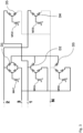
- Fig. 3 shows a selection network for the adaptor 103 for electrically connecting the lighting apparatus 101 to the electrified track 102 according to an embodiment.
- the selection of the phases L1, L2, L3 and N wire is integrated in a rectifying diode network D1, D2, D3, D4 and D5.
- Semi-conductors which are M47, M42, M40, M31 and M50 are provided, which can selectively connect a mid-point of the rectifier network with the ground potential of the driver.
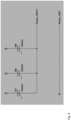
- Fig. 4 shows a selection network for the adaptor 103 for electrically connecting the lighting apparatus 101 to the electrified track 102 according to an embodiment.
- Fig. 3 The embodiment shown in Fig. 3 is a simplified selection network with 3 semiconductor switches U7, U8, U9 which may be triacs, provided upfront the converter electronics.
- the selection network can be simplified.
- Fig. 5 shows electronics in the adaptor 103 for electrically connecting a lighting apparatus 101 to an electrified track 102 according to an embodiment.
- Fig. 5 shows generally the electronics in the adapter according to an embodiment together with the terminals T1, T2 for feeding an LED-load 101 starting from the AC/DC converter.
- the supply micro-controller block 500 is the low-voltage power supply for the micro-controller 103a.
- the switching network 502 is controlled by a digital logic. This can e.g. be executed as ⁇ C 103a. The supply for the ⁇ C 103a can be done directly from the grid.
- the micro-controller 103a can be in functional connection with an interface 501, such that for example phase selection instructions can be provided wirelessly (NFC), in a wired manner (DALI-bus, etc.) or also by mechanical means on the adapter 103 itself.
- NFC wirelessly
- DALI-bus wired manner
- the micro-controller 103a senses the AC-voltage present at the different phases L1, L2, L3 and N (in order to detect the orientation). This AC voltage detection can also be used for an in-rush limiting switching on, which means that the micro-controller ⁇ C 103 switches active (conducting) the semi-conductor switch at a point in time, which is close to the zero-crossing of the AC sign wave.
- temporal sequences are stored, in which the electrical phase selection switch automatically changes the phase (working day / weekday).
- the electrical phase selection switch completely turns off the AC / DC part to minimize the standby losses.
- Fig. 6 shows a cross sectional view of an electrified track 102 according to an embodiment.
- the tracks typically have essentially the cross-sectional shape of a "U".
- the adapter 103 with integrated LED-driver electronics is inserted to be essentially flush with the U-shaped profile of the electrified track 102.
- the electrified track 102 carries four conductors, which are the AC main phases L1, L2, L3 as well as the neutral wire N.
- the adapter 103 is designed to selectively contact a combination of one of L1, L2, L3 with N.
- a simple addressing is possible when only a subset, preferably one of the phases L1, L2, L3 is switched in order to modify the electrical power sent to the adapter 103, which is actively connected to the corresponding phase L1, L2 or L3.
- the selection of the combinations of L and N wires for supplying a connected LED-load 101 is no longer done mechanically, but electronically inside the adaptor.
- the adapter mechanically contacts all electrical connections, L1, L2, L3 and N provided in the electrified track 102. These mechanical connections are then internally selectively connected.
- control unit 103a in the adapter 103 selectively connecting N and L1, L2, L3 contacts to the output terminals OUT, OUT 1 (see Fig. 2 ), which are then fed to the AC input of the driver electronics which is preferably also provided within the adapter 103.
- the electrical track 102 may be made of an electrically insulating material.
- the electrical track 102 holds three electrically conducting wires or lines, which are independently connected to the respective mains phases L1, L2 and L3.
- the electrical track 102 further holds an electrically conducting wire N, which is connected to the neutral or ground and which is symbolized in FIG. 6 .
- the electrical track 102 may define a chamber 104 for receiving the adapter 103.
- the adapter 103 may be completely inserted into the chamber 104 as visible in FIG. 6 .
Landscapes
- Engineering & Computer Science (AREA)
- General Engineering & Computer Science (AREA)
- Microelectronics & Electronic Packaging (AREA)
- Power Engineering (AREA)
- Business, Economics & Management (AREA)
- Emergency Management (AREA)
- Circuit Arrangement For Electric Light Sources In General (AREA)
- Arrangement Of Elements, Cooling, Sealing, Or The Like Of Lighting Devices (AREA)
Claims (12)
- Adapter (103) zum elektrischen Verbinden einer Beleuchtungseinrichtung (101) mit einer elektrifizierten Strecke (102), wobeidie elektrifizierte Strecke (102) Wechselstrom-Hauptphasen L1, L2 und L3 und einen Neutralleiter N umfasst, wobei der Adapter (103) ein Gehäuse aufweist, das gestaltet ist, um in ein U-förmiges Profil der elektrifizierten Strecke (102) eingefügt zu werden, wobei die elektrifizierte Strecke (102) eine U-förmige Querschnittsform aufweist, wobeider Adapter (103) Kontakte zum Kontaktieren der Wechselstrom-Hauptphasen L1, L2 und L3 und des Neutralleiters N der elektrifizierten Strecke (102) aufweist, wobeider Adapter (103) eine elektronische Steuereinheit (103a) in dem Gehäuse umfasst,wobei, wenn der Adapter (103) eingefügt wird, sämtliche Phasen L1, L2 und L3 und der Neutralleiter N der elektrifizierten Strecke (102) kontaktiert werden,wobei die Steuereinheit (103a) konfiguriert ist, um vorzugsweise unter Verwendung elektronischer Schalter eine Kombination einer der sämtlichen kontaktierten Wechselstrom-Hauptphasen L1, L2, L3 mit dem Neutralleiter N zum Versorgen der Beleuchtungseinrichtung (101) auszuwählen,gekennzeichnet dadurch:dass der Adapter (103) konfiguriert ist, um in zwei verschiedenen Ausrichtungen in die elektrifizierte Strecke (102) eingefügt zu werden,dass die zwei unterschiedlichen Ausrichtungen um 180 Grad gedreht sind,dass die Steuereinheit (103a) konfiguriert ist, um eine Einfügeausrichtung des Adapters (103) durch Erfassen einer Wechselspannung, die an den verschiedenen Phasen L1, L2, L3 und N vorhanden ist, zu erkennen.
- Adapter (103) nach Anspruch 1, wobei der Adapter (103) Anschlüsse umfasst, um die Beleuchtungseinrichtung (101), wie ein LED-Modul, zu versorgen.
- Adapter (103) nach Anspruch 1 oder 2, wobei die Steuereinheit (103a) konfiguriert ist, um eine der möglichen Kombinationen L1/N, L2/N und L3/N zu kontaktieren.
- Adapter (103) nach einem der vorstehenden Ansprüche, wobei der Adapter (103) LED-Treiberelektronik umfasst und konfiguriert ist, um vorzugsweise bündig mit dem U-förmigen Profil der elektrifizierten Strecke (102) eingefügt zu werden.
- Adapter (103) nach Anspruch 4, wobei die Steuereinheit (103a) konfiguriert ist, um selektiv eine Kombination aus einer von L1, L2, L3 mit N elektronisch innerhalb des Adapters (103) mit Ausgangsanschlüssen zu kontaktieren, wobei die Ausgangsanschlüsse einem Wechselstromeingang der LED-Treiberelektronik zugeführt sind.
- Adapter (103) nach einem der vorstehenden Ansprüche, wobei der Adapter (103) ferner ein Auswahlnetzwerk zum Auswählen der L1, L2, L2 und des Leiters N umfasst, wobei das Auswahlnetzwerk eine Vielzahl steuerbarer elektronischer Schalter wie etwa Symistoren oder Hochspannungstransistoren umfasst.
- Adapter (103) nach einem der vorstehenden Ansprüche 1 bis 5, wobei die Steuereinheit (103a) ferner konfiguriert ist, um L1, L2, L2 und den Leiter N basierend auf einem Gleichrichterdiodennetzwerk auszuwählen.
- Adapter (103) nach einem der vorstehenden Ansprüche, ferner umfassend mechanische Maßnahmen, die in das Gehäuse des Adapters (103) derart integriert sind, dass der Adapter (103) konfiguriert ist, um nur in einer vorbestimmten Ausrichtung in die elektrifizierte Strecke (102) eingefügt zu werden.
- Adapter (103) nach einem der vorstehenden Ansprüche, wobei die Steuereinheit (103a) mit einer Schnittstelle (501) verbunden ist.
- Adapter (103) nach Anspruch 9, wobei die Schnittstelle (501) eine drahtlose Schnittstelle, wie eine NFC-Schnittstelle, oder eine drahtgebundene Schnittstelle, wie eine DALI-Busschnittstelle, ist.
- Adapter (103) nach Anspruch 9, wobei die Schnittstelle (501) mechanische Mittel an dem Adapter (103) selbst umfasst.
- System (100), umfassend eine elektrifizierte Strecke (102), umfassend Wechselstrom-Hauptphasen L1, L2 und L3 und einen Neutralleiter N und einen Adapter (103) nach einem der vorstehenden Ansprüche 1 bis 11.
Priority Applications (4)
| Application Number | Priority Date | Filing Date | Title |
|---|---|---|---|
| EP19194588.0A EP3787375B1 (de) | 2019-08-30 | 2019-08-30 | Adapter zum elektrischen verbinden einer beleuchtungsvorrichtung mit einer elektrischen schiene |
| PCT/EP2020/072962 WO2021037595A1 (en) | 2019-08-30 | 2020-08-17 | Adapter for electrically connecting a lighting device to an electrical track |
| CN202080054958.2A CN114174719B (zh) | 2019-08-30 | 2020-08-17 | 用于将照明设备电连接到电气轨道的适配器 |
| US17/633,674 US12062872B2 (en) | 2019-08-30 | 2020-08-17 | Adapter for electrically connecting a lighting device to an electrical track |
Applications Claiming Priority (1)
| Application Number | Priority Date | Filing Date | Title |
|---|---|---|---|
| EP19194588.0A EP3787375B1 (de) | 2019-08-30 | 2019-08-30 | Adapter zum elektrischen verbinden einer beleuchtungsvorrichtung mit einer elektrischen schiene |
Publications (2)
| Publication Number | Publication Date |
|---|---|
| EP3787375A1 EP3787375A1 (de) | 2021-03-03 |
| EP3787375B1 true EP3787375B1 (de) | 2024-10-02 |
Family
ID=67875228
Family Applications (1)
| Application Number | Title | Priority Date | Filing Date |
|---|---|---|---|
| EP19194588.0A Active EP3787375B1 (de) | 2019-08-30 | 2019-08-30 | Adapter zum elektrischen verbinden einer beleuchtungsvorrichtung mit einer elektrischen schiene |
Country Status (4)
| Country | Link |
|---|---|
| US (1) | US12062872B2 (de) |
| EP (1) | EP3787375B1 (de) |
| CN (1) | CN114174719B (de) |
| WO (1) | WO2021037595A1 (de) |
Citations (2)
| Publication number | Priority date | Publication date | Assignee | Title |
|---|---|---|---|---|
| DE3818078A1 (de) * | 1988-05-25 | 1989-12-07 | Wago Verwaltungs Gmbh | Elektrische steckvorrichtung mit phasenwahl |
| DE102012208297A1 (de) * | 2012-05-16 | 2013-11-21 | Trilux Gmbh & Co. Kg | Stromversorgungsanordnung mit Phasenwahl für eine Leuchte |
Family Cites Families (16)
| Publication number | Priority date | Publication date | Assignee | Title |
|---|---|---|---|---|
| ATE104041T1 (de) * | 1990-11-19 | 1994-04-15 | Siemens Ag | Lichtband. |
| DE4127899C2 (de) * | 1991-08-22 | 2000-04-06 | Wago Verwaltungs Gmbh | Elektrische Steckvorrichtung mit Phasenwahl |
| FI101756B (fi) * | 1996-03-13 | 1998-08-14 | Nordic Aluminium Oyj | Virranottolaite kosketinkiskoa varten |
| EP1016821B2 (de) * | 1998-12-30 | 2014-01-08 | Zumtobel Lighting GmbH | Lichtband-System mit einer an einer Wand oder Decke zu befestigenden Tragschiene |
| US8931667B2 (en) * | 2008-09-24 | 2015-01-13 | The Procter & Gamble Company | Methods and apparatuses for dispensing fluids |
| KR100929818B1 (ko) * | 2009-10-17 | 2009-12-07 | 주식회사 중원파워컨트롤스 | 화재 방지용 절전 지능 매입 콘센트 |
| AT12652U1 (de) * | 2011-04-08 | 2012-09-15 | Tridonic Connection Technology Gmbh & Co Kg | Vorrichtung zum befestigen und kontaktieren eines leuchtmittels und/oder eines leuchtmoduls, sowie leuchte |
| DE102012007084B4 (de) * | 2012-04-11 | 2014-04-24 | Hoffmeister Leuchten Gmbh | Adapter |
| DE202013102943U1 (de) * | 2013-07-04 | 2014-07-07 | studio dinnebier Dinnebier Blieske GbR (vertretungsberechtigte Gesellschafter: Johannes Dinnebier, 13008 Berlin und Jan Blieske, 14195 Berlin) | Stromschienenadapter und Anordnung mit Stromschienenadapter und Stromschiene |
| KR102117639B1 (ko) * | 2013-09-04 | 2020-06-02 | 삼성디스플레이 주식회사 | 표시장치용 윈도우, 이의 제조 방법 및 이를 포함하는 표시 장치 |
| US9467006B2 (en) * | 2013-09-23 | 2016-10-11 | Trippe Manufacturing Company | Automatic transfer switch for three-phase applications |
| CN203827549U (zh) * | 2014-05-04 | 2014-09-10 | 中国医药集团重庆医药设计院 | 集中应急电源供电的火灾应急照明配电及控制电路 |
| ITUA20161482A1 (it) | 2016-03-09 | 2017-09-09 | A A G Stucchi S R L | Adattatore perfezionato di supporto e collegamento di apparecchi di illuminazione a binari elettrificati e gruppo di illuminazione impiegante lo stesso |
| KR102170996B1 (ko) * | 2016-05-05 | 2020-10-28 | 권익수 | 팬텀 전압 검출기가 있는 정전 감지 시스템 |
| US10116108B1 (en) * | 2016-11-01 | 2018-10-30 | Green Creative Ltd. | Track-lighting adapter with universal housing |
| CN107124033A (zh) * | 2017-05-22 | 2017-09-01 | 合肥联信电源有限公司 | 一种输出无间断切换的应急电源系统 |
-
2019
- 2019-08-30 EP EP19194588.0A patent/EP3787375B1/de active Active
-
2020
- 2020-08-17 WO PCT/EP2020/072962 patent/WO2021037595A1/en not_active Ceased
- 2020-08-17 CN CN202080054958.2A patent/CN114174719B/zh active Active
- 2020-08-17 US US17/633,674 patent/US12062872B2/en active Active
Patent Citations (2)
| Publication number | Priority date | Publication date | Assignee | Title |
|---|---|---|---|---|
| DE3818078A1 (de) * | 1988-05-25 | 1989-12-07 | Wago Verwaltungs Gmbh | Elektrische steckvorrichtung mit phasenwahl |
| DE102012208297A1 (de) * | 2012-05-16 | 2013-11-21 | Trilux Gmbh & Co. Kg | Stromversorgungsanordnung mit Phasenwahl für eine Leuchte |
Also Published As
| Publication number | Publication date |
|---|---|
| US20220316670A1 (en) | 2022-10-06 |
| US12062872B2 (en) | 2024-08-13 |
| WO2021037595A1 (en) | 2021-03-04 |
| CN114174719A (zh) | 2022-03-11 |
| CN114174719B (zh) | 2025-04-01 |
| EP3787375A1 (de) | 2021-03-03 |
Similar Documents
| Publication | Publication Date | Title |
|---|---|---|
| US10492260B2 (en) | LED lighting system | |
| US7928663B1 (en) | Lighting dimmer adaptable to four wiring configurations | |
| CN102246376B (zh) | 用于配电单元的通用电力入口系统 | |
| US20100289415A1 (en) | Energy efficient decorative lighting | |
| US20120242234A1 (en) | Low Voltage Coupling Design | |
| CN101779523A (zh) | 自供电led旁路开关配置 | |
| US20220052619A1 (en) | Apparatus and method for persistent dc power panel conversion | |
| RU2663827C1 (ru) | Устройство для преобразования питания | |
| EP3787375B1 (de) | Adapter zum elektrischen verbinden einer beleuchtungsvorrichtung mit einer elektrischen schiene | |
| CN106488605A (zh) | 光输出控制装置、照明系统和设施设备 | |
| US9763333B2 (en) | Shared resistor pad bypass | |
| EP3755123B1 (de) | Kommunikationsschnittstelle für beleuchtungsmittel | |
| US12247726B2 (en) | Support rails for luminaires or electrical units | |
| US20070268634A1 (en) | Power supply system | |
| CN110291845A (zh) | 可反转极性的布线系统 | |
| US20170059142A1 (en) | Led light fixtures | |
| CN109275222A (zh) | 三路全向led灯驱动器电路 | |
| US6417580B1 (en) | Power supply booster | |
| KR102696178B1 (ko) | 배터리 시스템에서 배터리 팩의 채널번호 자동 지정방법 | |
| CN215498559U (zh) | 适应多种电源供电的窗帘电控结构 | |
| CN111010777A (zh) | 控制电路和设备控制系统 | |
| KR19990047167A (ko) | 다출력 교류 어댑터 | |
| US7465179B1 (en) | Base for installation of energy-efficient light bulbs | |
| EP4573849A1 (de) | Beleuchtungssteuerungsvorrichtung mit luftspaltschaltergesteuertem ausgang | |
| CN210898994U (zh) | 一种电机驱动装置及电机运行系统 |
Legal Events
| Date | Code | Title | Description |
|---|---|---|---|
| PUAI | Public reference made under article 153(3) epc to a published international application that has entered the european phase |
Free format text: ORIGINAL CODE: 0009012 |
|
| STAA | Information on the status of an ep patent application or granted ep patent |
Free format text: STATUS: THE APPLICATION HAS BEEN PUBLISHED |
|
| AK | Designated contracting states |
Kind code of ref document: A1 Designated state(s): AL AT BE BG CH CY CZ DE DK EE ES FI FR GB GR HR HU IE IS IT LI LT LU LV MC MK MT NL NO PL PT RO RS SE SI SK SM TR |
|
| AX | Request for extension of the european patent |
Extension state: BA ME |
|
| STAA | Information on the status of an ep patent application or granted ep patent |
Free format text: STATUS: REQUEST FOR EXAMINATION WAS MADE |
|
| 17P | Request for examination filed |
Effective date: 20210813 |
|
| RBV | Designated contracting states (corrected) |
Designated state(s): AL AT BE BG CH CY CZ DE DK EE ES FI FR GB GR HR HU IE IS IT LI LT LU LV MC MK MT NL NO PL PT RO RS SE SI SK SM TR |
|
| STAA | Information on the status of an ep patent application or granted ep patent |
Free format text: STATUS: EXAMINATION IS IN PROGRESS |
|
| 17Q | First examination report despatched |
Effective date: 20220621 |
|
| REG | Reference to a national code |
Ref legal event code: R079 Free format text: PREVIOUS MAIN CLASS: H05B0045000000 Ref country code: DE Ref legal event code: R079 Ref document number: 602019059671 Country of ref document: DE Free format text: PREVIOUS MAIN CLASS: H05B0045000000 Ipc: H02J0009060000 |
|
| GRAP | Despatch of communication of intention to grant a patent |
Free format text: ORIGINAL CODE: EPIDOSNIGR1 |
|
| STAA | Information on the status of an ep patent application or granted ep patent |
Free format text: STATUS: GRANT OF PATENT IS INTENDED |
|
| RIC1 | Information provided on ipc code assigned before grant |
Ipc: H05B 47/00 20200101ALI20240320BHEP Ipc: H02J 9/06 20060101AFI20240320BHEP |
|
| INTG | Intention to grant announced |
Effective date: 20240409 |
|
| GRAS | Grant fee paid |
Free format text: ORIGINAL CODE: EPIDOSNIGR3 |
|
| GRAA | (expected) grant |
Free format text: ORIGINAL CODE: 0009210 |
|
| STAA | Information on the status of an ep patent application or granted ep patent |
Free format text: STATUS: THE PATENT HAS BEEN GRANTED |
|
| P01 | Opt-out of the competence of the unified patent court (upc) registered |
Free format text: CASE NUMBER: APP_44204/2024 Effective date: 20240730 |
|
| AK | Designated contracting states |
Kind code of ref document: B1 Designated state(s): AL AT BE BG CH CY CZ DE DK EE ES FI FR GB GR HR HU IE IS IT LI LT LU LV MC MK MT NL NO PL PT RO RS SE SI SK SM TR |
|
| REG | Reference to a national code |
Ref country code: GB Ref legal event code: FG4D |
|
| REG | Reference to a national code |
Ref country code: CH Ref legal event code: EP |
|
| REG | Reference to a national code |
Ref country code: IE Ref legal event code: FG4D |
|
| REG | Reference to a national code |
Ref country code: DE Ref legal event code: R096 Ref document number: 602019059671 Country of ref document: DE |
|
| REG | Reference to a national code |
Ref country code: DE Ref legal event code: R084 Ref document number: 602019059671 Country of ref document: DE |
|
| REG | Reference to a national code |
Ref country code: LT Ref legal event code: MG9D |
|
| REG | Reference to a national code |
Ref country code: NL Ref legal event code: MP Effective date: 20241002 |
|
| REG | Reference to a national code |
Ref country code: AT Ref legal event code: MK05 Ref document number: 1729163 Country of ref document: AT Kind code of ref document: T Effective date: 20241002 |
|
| PG25 | Lapsed in a contracting state [announced via postgrant information from national office to epo] |
Ref country code: NL Free format text: LAPSE BECAUSE OF FAILURE TO SUBMIT A TRANSLATION OF THE DESCRIPTION OR TO PAY THE FEE WITHIN THE PRESCRIBED TIME-LIMIT Effective date: 20241002 |
|
| PG25 | Lapsed in a contracting state [announced via postgrant information from national office to epo] |
Ref country code: NL Free format text: LAPSE BECAUSE OF FAILURE TO SUBMIT A TRANSLATION OF THE DESCRIPTION OR TO PAY THE FEE WITHIN THE PRESCRIBED TIME-LIMIT Effective date: 20241002 |
|
| PG25 | Lapsed in a contracting state [announced via postgrant information from national office to epo] |
Ref country code: HR Free format text: LAPSE BECAUSE OF FAILURE TO SUBMIT A TRANSLATION OF THE DESCRIPTION OR TO PAY THE FEE WITHIN THE PRESCRIBED TIME-LIMIT Effective date: 20241002 Ref country code: PT Free format text: LAPSE BECAUSE OF FAILURE TO SUBMIT A TRANSLATION OF THE DESCRIPTION OR TO PAY THE FEE WITHIN THE PRESCRIBED TIME-LIMIT Effective date: 20250203 Ref country code: IS Free format text: LAPSE BECAUSE OF FAILURE TO SUBMIT A TRANSLATION OF THE DESCRIPTION OR TO PAY THE FEE WITHIN THE PRESCRIBED TIME-LIMIT Effective date: 20250202 |
|
| PG25 | Lapsed in a contracting state [announced via postgrant information from national office to epo] |
Ref country code: FI Free format text: LAPSE BECAUSE OF FAILURE TO SUBMIT A TRANSLATION OF THE DESCRIPTION OR TO PAY THE FEE WITHIN THE PRESCRIBED TIME-LIMIT Effective date: 20241002 |
|
| PG25 | Lapsed in a contracting state [announced via postgrant information from national office to epo] |
Ref country code: BG Free format text: LAPSE BECAUSE OF FAILURE TO SUBMIT A TRANSLATION OF THE DESCRIPTION OR TO PAY THE FEE WITHIN THE PRESCRIBED TIME-LIMIT Effective date: 20241002 |
|
| PG25 | Lapsed in a contracting state [announced via postgrant information from national office to epo] |
Ref country code: ES Free format text: LAPSE BECAUSE OF FAILURE TO SUBMIT A TRANSLATION OF THE DESCRIPTION OR TO PAY THE FEE WITHIN THE PRESCRIBED TIME-LIMIT Effective date: 20241002 |
|
| PG25 | Lapsed in a contracting state [announced via postgrant information from national office to epo] |
Ref country code: NO Free format text: LAPSE BECAUSE OF FAILURE TO SUBMIT A TRANSLATION OF THE DESCRIPTION OR TO PAY THE FEE WITHIN THE PRESCRIBED TIME-LIMIT Effective date: 20250102 |
|
| PG25 | Lapsed in a contracting state [announced via postgrant information from national office to epo] |
Ref country code: AT Free format text: LAPSE BECAUSE OF FAILURE TO SUBMIT A TRANSLATION OF THE DESCRIPTION OR TO PAY THE FEE WITHIN THE PRESCRIBED TIME-LIMIT Effective date: 20241002 Ref country code: GR Free format text: LAPSE BECAUSE OF FAILURE TO SUBMIT A TRANSLATION OF THE DESCRIPTION OR TO PAY THE FEE WITHIN THE PRESCRIBED TIME-LIMIT Effective date: 20250103 Ref country code: LV Free format text: LAPSE BECAUSE OF FAILURE TO SUBMIT A TRANSLATION OF THE DESCRIPTION OR TO PAY THE FEE WITHIN THE PRESCRIBED TIME-LIMIT Effective date: 20241002 |
|
| PG25 | Lapsed in a contracting state [announced via postgrant information from national office to epo] |
Ref country code: CZ Free format text: LAPSE BECAUSE OF FAILURE TO SUBMIT A TRANSLATION OF THE DESCRIPTION OR TO PAY THE FEE WITHIN THE PRESCRIBED TIME-LIMIT Effective date: 20241002 Ref country code: PL Free format text: LAPSE BECAUSE OF FAILURE TO SUBMIT A TRANSLATION OF THE DESCRIPTION OR TO PAY THE FEE WITHIN THE PRESCRIBED TIME-LIMIT Effective date: 20241002 |
|
| PG25 | Lapsed in a contracting state [announced via postgrant information from national office to epo] |
Ref country code: RS Free format text: LAPSE BECAUSE OF FAILURE TO SUBMIT A TRANSLATION OF THE DESCRIPTION OR TO PAY THE FEE WITHIN THE PRESCRIBED TIME-LIMIT Effective date: 20250102 |
|
| PG25 | Lapsed in a contracting state [announced via postgrant information from national office to epo] |
Ref country code: SM Free format text: LAPSE BECAUSE OF FAILURE TO SUBMIT A TRANSLATION OF THE DESCRIPTION OR TO PAY THE FEE WITHIN THE PRESCRIBED TIME-LIMIT Effective date: 20241002 |
|
| REG | Reference to a national code |
Ref country code: DE Ref legal event code: R097 Ref document number: 602019059671 Country of ref document: DE |
|
| PG25 | Lapsed in a contracting state [announced via postgrant information from national office to epo] |
Ref country code: DK Free format text: LAPSE BECAUSE OF FAILURE TO SUBMIT A TRANSLATION OF THE DESCRIPTION OR TO PAY THE FEE WITHIN THE PRESCRIBED TIME-LIMIT Effective date: 20241002 |
|
| PG25 | Lapsed in a contracting state [announced via postgrant information from national office to epo] |
Ref country code: EE Free format text: LAPSE BECAUSE OF FAILURE TO SUBMIT A TRANSLATION OF THE DESCRIPTION OR TO PAY THE FEE WITHIN THE PRESCRIBED TIME-LIMIT Effective date: 20241002 |
|
| PG25 | Lapsed in a contracting state [announced via postgrant information from national office to epo] |
Ref country code: RO Free format text: LAPSE BECAUSE OF FAILURE TO SUBMIT A TRANSLATION OF THE DESCRIPTION OR TO PAY THE FEE WITHIN THE PRESCRIBED TIME-LIMIT Effective date: 20241002 |
|
| PG25 | Lapsed in a contracting state [announced via postgrant information from national office to epo] |
Ref country code: SK Free format text: LAPSE BECAUSE OF FAILURE TO SUBMIT A TRANSLATION OF THE DESCRIPTION OR TO PAY THE FEE WITHIN THE PRESCRIBED TIME-LIMIT Effective date: 20241002 |
|
| PG25 | Lapsed in a contracting state [announced via postgrant information from national office to epo] |
Ref country code: IT Free format text: LAPSE BECAUSE OF FAILURE TO SUBMIT A TRANSLATION OF THE DESCRIPTION OR TO PAY THE FEE WITHIN THE PRESCRIBED TIME-LIMIT Effective date: 20241002 |
|
| PLBE | No opposition filed within time limit |
Free format text: ORIGINAL CODE: 0009261 |
|
| STAA | Information on the status of an ep patent application or granted ep patent |
Free format text: STATUS: NO OPPOSITION FILED WITHIN TIME LIMIT |
|
| PG25 | Lapsed in a contracting state [announced via postgrant information from national office to epo] |
Ref country code: SE Free format text: LAPSE BECAUSE OF FAILURE TO SUBMIT A TRANSLATION OF THE DESCRIPTION OR TO PAY THE FEE WITHIN THE PRESCRIBED TIME-LIMIT Effective date: 20241002 |
|
| 26N | No opposition filed |
Effective date: 20250703 |
|
| PGFP | Annual fee paid to national office [announced via postgrant information from national office to epo] |
Ref country code: DE Payment date: 20250827 Year of fee payment: 7 |
|
| PGFP | Annual fee paid to national office [announced via postgrant information from national office to epo] |
Ref country code: GB Payment date: 20250826 Year of fee payment: 7 |
|
| PGFP | Annual fee paid to national office [announced via postgrant information from national office to epo] |
Ref country code: FR Payment date: 20250825 Year of fee payment: 7 |