EP3787375B1 - Adapter for electrically connecting a lighting device to an electrical track - Google Patents
Adapter for electrically connecting a lighting device to an electrical track Download PDFInfo
- Publication number
- EP3787375B1 EP3787375B1 EP19194588.0A EP19194588A EP3787375B1 EP 3787375 B1 EP3787375 B1 EP 3787375B1 EP 19194588 A EP19194588 A EP 19194588A EP 3787375 B1 EP3787375 B1 EP 3787375B1
- Authority
- EP
- European Patent Office
- Prior art keywords
- adaptor
- electrified track
- control unit
- track
- interface
- Prior art date
- Legal status (The legal status is an assumption and is not a legal conclusion. Google has not performed a legal analysis and makes no representation as to the accuracy of the status listed.)
- Active
Links
Images


Classifications
-
- F—MECHANICAL ENGINEERING; LIGHTING; HEATING; WEAPONS; BLASTING
- F21—LIGHTING
- F21V—FUNCTIONAL FEATURES OR DETAILS OF LIGHTING DEVICES OR SYSTEMS THEREOF; STRUCTURAL COMBINATIONS OF LIGHTING DEVICES WITH OTHER ARTICLES, NOT OTHERWISE PROVIDED FOR
- F21V23/00—Arrangement of electric circuit elements in or on lighting devices
- F21V23/06—Arrangement of electric circuit elements in or on lighting devices the elements being coupling devices, e.g. connectors
-
- H—ELECTRICITY
- H02—GENERATION; CONVERSION OR DISTRIBUTION OF ELECTRIC POWER
- H02J—ELECTRIC POWER NETWORKS; CIRCUIT ARRANGEMENTS OR SYSTEMS FOR SUPPLYING OR DISTRIBUTING ELECTRIC POWER; SYSTEMS FOR STORING ELECTRIC ENERGY
- H02J3/00—Circuit arrangements for AC mains or AC distribution networks
- H02J3/007—Arrangements for selectively connecting one or more loads to one or more power sources or power lines
-
- F—MECHANICAL ENGINEERING; LIGHTING; HEATING; WEAPONS; BLASTING
- F21—LIGHTING
- F21V—FUNCTIONAL FEATURES OR DETAILS OF LIGHTING DEVICES OR SYSTEMS THEREOF; STRUCTURAL COMBINATIONS OF LIGHTING DEVICES WITH OTHER ARTICLES, NOT OTHERWISE PROVIDED FOR
- F21V23/00—Arrangement of electric circuit elements in or on lighting devices
-
- H—ELECTRICITY
- H01—ELECTRIC ELEMENTS
- H01R—ELECTRICALLY-CONDUCTIVE CONNECTIONS; STRUCTURAL ASSOCIATIONS OF A PLURALITY OF MUTUALLY-INSULATED ELECTRICAL CONNECTING ELEMENTS; COUPLING DEVICES; CURRENT COLLECTORS
- H01R13/00—Details of coupling devices of the kinds covered by groups H01R12/70 or H01R24/00 - H01R33/00
- H01R13/66—Structural association with built-in electrical component
- H01R13/665—Structural association with built-in electrical component with built-in electronic circuit
-
- H—ELECTRICITY
- H02—GENERATION; CONVERSION OR DISTRIBUTION OF ELECTRIC POWER
- H02J—ELECTRIC POWER NETWORKS; CIRCUIT ARRANGEMENTS OR SYSTEMS FOR SUPPLYING OR DISTRIBUTING ELECTRIC POWER; SYSTEMS FOR STORING ELECTRIC ENERGY
- H02J9/00—Circuit arrangements for emergency or stand-by power supply, e.g. for emergency lighting
- H02J9/04—Circuit arrangements for emergency or stand-by power supply, e.g. for emergency lighting in which the distribution system is disconnected from the normal source and connected to a standby source
- H02J9/06—Circuit arrangements for emergency or stand-by power supply, e.g. for emergency lighting in which the distribution system is disconnected from the normal source and connected to a standby source with automatic change-over, e.g. UPS systems
- H02J9/062—Circuit arrangements for emergency or stand-by power supply, e.g. for emergency lighting in which the distribution system is disconnected from the normal source and connected to a standby source with automatic change-over, e.g. UPS systems for AC powered loads
- H02J9/065—Circuit arrangements for emergency or stand-by power supply, e.g. for emergency lighting in which the distribution system is disconnected from the normal source and connected to a standby source with automatic change-over, e.g. UPS systems for AC powered loads for lighting purposes
-
- H—ELECTRICITY
- H05—ELECTRIC TECHNIQUES NOT OTHERWISE PROVIDED FOR
- H05B—ELECTRIC HEATING; ELECTRIC LIGHT SOURCES NOT OTHERWISE PROVIDED FOR; CIRCUIT ARRANGEMENTS FOR ELECTRIC LIGHT SOURCES, IN GENERAL
- H05B47/00—Circuit arrangements for operating light sources in general, i.e. where the type of light source is not relevant
Definitions
- the invention relates to an adaptor for electrically connecting a lighting apparatus to an electrified track.
- the invention further relates to a system comprising an electrified track and an adaptor.
- EP3217090A1 proposes a lighting system comprising an electrical track having three mains phases and an adapter for electrically connecting a lighting device to the electrical track, such that the lighting device may receive power from the mains.
- the adapter supports the lighting device, for example a spotlight.
- the electrical track may hold several adapters, hence several lighting devices, which are for example arranged in a row.
- the adapter includes a mechanism configured for extracting contacts automatically when the adapter is fitted in the electrical track, such that the contacts are electrically connected to the three mains phases.
- the known adapter presents some drawbacks and limitations.
- the automatic connection of the contacts to the three mains phases limits the flexibility in the electrical connection possibilities.
- EP 0 486 714 A1 discloses a light band, wherein for an easy and fast assembly of light bands the required feed-through wiring on the side of the carrier rail can be designed as a conductor rail.
- DE 10 2012 208 297 A1 discloses a current supply arrangement with phase selection for a luminaire.
- an adaptor for electrically connecting a lighting apparatus to an electrified track comprises AC main phases L1, L2 and L3 and a neutral wire N
- the adaptor has a housing designed to be inserted into a U-shaped profile of the electrified track
- the adaptor has contacts for contacting the AC main phases L1, L2 and L3 and the neutral wire N of the electrified track
- the adaptor comprises an electronic control unit in the housing, and the control unit is configured to select a combination of one of the all contacted AC main phases L1, L2, L3 with the neutral wire N for supplying the lighting apparatus.
- the control unit is configured to detect an insertion orientation of the adaptor by sensing an AC-voltage present at the different phases L1, L2, L3 and N.
- the adaptor comprises terminals in order to supply the lighting apparatus, such as an LED module.
- control unit is configured to contact one of the possible combinations L1/N, L2/N and L3/N.
- the electrical phase selection switch can respond to a power failure of one phase and automatically switch to another phase non-affected by power failure.
- the adaptor is configured to be inserted into the electrified track in two different orientations.
- the two different orientations are rotated by 180 degrees.
- the electrified track has a cross-sectional shape of U.
- the adaptor comprises LED-driver electronics and is configured to be inserted preferably flush with the U-shaped profile of the electrified track.
- control unit is configured to selectively contact a combination of one of L1, L2, L3 with N electronically inside the adaptor to output terminals, wherein the output terminals are fed to an AC input of the LED-driver electronics.
- the adaptor further comprises a selection network for selecting the L1, L2, L2 and N wire, wherein the selection network comprises a plurality of controllable high voltage semi-conductor switches, such as triacs or high voltage transistors.
- control unit is further configured to select L1, L2, L2 and N wire based on a rectifying diode network.
- the adaptor further comprises mechanical measures integrated in the housing such that the adaptor can only be inserted in one predetermined orientation in the electrified track.
- control unit is connected with an interface.
- the interface is a wireless interface such as an NFC interface or a wired interface such as a DALI bus interface.
- phase has no longer to be set manually, but can also be adjusted, for example via DALI bus interface.
- the interface comprises mechanical means on the adaptor itself.
- the invention also relates to a system comprising an electrified track comprising AC main phases L1, L2 and L3 and a neutral wire N, and an adaptor according to the first aspect or any one of the implementation forms thereof.
- the aspect of the present invention might contain integrated circuits that are readily manufacturable using conventional semiconductor technologies, such as complementary metal-oxide semiconductor technology, short "CMOS".
- CMOS complementary metal-oxide semiconductor technology
- the aspects of the present invention may be implemented with other manufacturing processes for making optical as well as electrical devices.
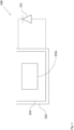
- Fig. 1 shows a system 100 comprising an adaptor 103 for electrically connecting a lighting apparatus 101 to an electrified track 102 according to an embodiment.
- the electrified track 102 comprises AC main phases L1, L2 and L3 and a neutral wire N.
- the adaptor 103 has a housing designed to be inserted into a U-shaped profile of the electrified track 102, wherein the adaptor 103 has contacts for contacting the AC main phases L1, L2 and L3 and the neutral wire N of the electrified track 102.
- the adaptor 103 comprises an electronic control unit 103a in the housing, wherein the control unit 103a is configured to select a combination of one of the all connected AC main phases L1, L2, L3 with the neutral wire N for supplying the lighting apparatus 101.
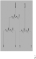
- Fig. 2 shows a selection network for an adaptor 103 for electrically connecting a lighting apparatus 101 to the electrified track 102 according to an embodiment.
- a situation is shown in which the adapter 103 can be inserted into the electrified track 102 in two different orientations (rotated by 180 degree), such that, depending on the insertion orientation of the adapter 103, different contacts can actually be contacted to the contacts of the adapter 103.
- a low-power voltage supply is provided such that already in this state (in which no phase is connected to the output), a control circuitry or electronic control unit 103a, such as for example a micro-controller of the driver is powered.
- the control circuitry 103a detects the insertion orientation of the adapter by sensing at which contacts actually voltage is present.
- control circuitry 103a is supplied in a wireless or in a wired manner with the instructions as which of the L1, L2 and L3 shall be switched active in combination with the N wire.
- a selection network which comprises a plurality of controllable high voltage semi-conductor switches, such as triacs U1, U2, U3, U4, U5 and U6 or high voltage transistors.
- control circuitry or electronic control unit 103a controls the semi-conductor switches such that the desired phase L1, L2, L3 is switched active in combination with the N wire.
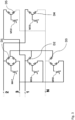
- Fig. 3 shows a selection network for the adaptor 103 for electrically connecting the lighting apparatus 101 to the electrified track 102 according to an embodiment.
- the selection of the phases L1, L2, L3 and N wire is integrated in a rectifying diode network D1, D2, D3, D4 and D5.
- Semi-conductors which are M47, M42, M40, M31 and M50 are provided, which can selectively connect a mid-point of the rectifier network with the ground potential of the driver.
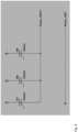
- Fig. 4 shows a selection network for the adaptor 103 for electrically connecting the lighting apparatus 101 to the electrified track 102 according to an embodiment.
- Fig. 3 The embodiment shown in Fig. 3 is a simplified selection network with 3 semiconductor switches U7, U8, U9 which may be triacs, provided upfront the converter electronics.
- the selection network can be simplified.
- Fig. 5 shows electronics in the adaptor 103 for electrically connecting a lighting apparatus 101 to an electrified track 102 according to an embodiment.
- Fig. 5 shows generally the electronics in the adapter according to an embodiment together with the terminals T1, T2 for feeding an LED-load 101 starting from the AC/DC converter.
- the supply micro-controller block 500 is the low-voltage power supply for the micro-controller 103a.
- the switching network 502 is controlled by a digital logic. This can e.g. be executed as ⁇ C 103a. The supply for the ⁇ C 103a can be done directly from the grid.
- the micro-controller 103a can be in functional connection with an interface 501, such that for example phase selection instructions can be provided wirelessly (NFC), in a wired manner (DALI-bus, etc.) or also by mechanical means on the adapter 103 itself.
- NFC wirelessly
- DALI-bus wired manner
- the micro-controller 103a senses the AC-voltage present at the different phases L1, L2, L3 and N (in order to detect the orientation). This AC voltage detection can also be used for an in-rush limiting switching on, which means that the micro-controller ⁇ C 103 switches active (conducting) the semi-conductor switch at a point in time, which is close to the zero-crossing of the AC sign wave.
- temporal sequences are stored, in which the electrical phase selection switch automatically changes the phase (working day / weekday).
- the electrical phase selection switch completely turns off the AC / DC part to minimize the standby losses.
- Fig. 6 shows a cross sectional view of an electrified track 102 according to an embodiment.
- the tracks typically have essentially the cross-sectional shape of a "U".
- the adapter 103 with integrated LED-driver electronics is inserted to be essentially flush with the U-shaped profile of the electrified track 102.
- the electrified track 102 carries four conductors, which are the AC main phases L1, L2, L3 as well as the neutral wire N.
- the adapter 103 is designed to selectively contact a combination of one of L1, L2, L3 with N.
- a simple addressing is possible when only a subset, preferably one of the phases L1, L2, L3 is switched in order to modify the electrical power sent to the adapter 103, which is actively connected to the corresponding phase L1, L2 or L3.
- the selection of the combinations of L and N wires for supplying a connected LED-load 101 is no longer done mechanically, but electronically inside the adaptor.
- the adapter mechanically contacts all electrical connections, L1, L2, L3 and N provided in the electrified track 102. These mechanical connections are then internally selectively connected.
- control unit 103a in the adapter 103 selectively connecting N and L1, L2, L3 contacts to the output terminals OUT, OUT 1 (see Fig. 2 ), which are then fed to the AC input of the driver electronics which is preferably also provided within the adapter 103.
- the electrical track 102 may be made of an electrically insulating material.
- the electrical track 102 holds three electrically conducting wires or lines, which are independently connected to the respective mains phases L1, L2 and L3.
- the electrical track 102 further holds an electrically conducting wire N, which is connected to the neutral or ground and which is symbolized in FIG. 6 .
- the electrical track 102 may define a chamber 104 for receiving the adapter 103.
- the adapter 103 may be completely inserted into the chamber 104 as visible in FIG. 6 .
Landscapes
- Engineering & Computer Science (AREA)
- General Engineering & Computer Science (AREA)
- Microelectronics & Electronic Packaging (AREA)
- Power Engineering (AREA)
- Business, Economics & Management (AREA)
- Emergency Management (AREA)
- Circuit Arrangement For Electric Light Sources In General (AREA)
- Arrangement Of Elements, Cooling, Sealing, Or The Like Of Lighting Devices (AREA)
Description
- The invention relates to an adaptor for electrically connecting a lighting apparatus to an electrified track. The invention further relates to a system comprising an electrified track and an adaptor.
-
EP3217090A1 proposes a lighting system comprising an electrical track having three mains phases and an adapter for electrically connecting a lighting device to the electrical track, such that the lighting device may receive power from the mains. The adapter supports the lighting device, for example a spotlight. The electrical track may hold several adapters, hence several lighting devices, which are for example arranged in a row. In order to enable an operator to adjust the number and locations of the adapters on the electrical track, the adapter includes a mechanism configured for extracting contacts automatically when the adapter is fitted in the electrical track, such that the contacts are electrically connected to the three mains phases. - However, the known adapter presents some drawbacks and limitations. First, it has a relatively complex structure and it requires numerous components, thus increasing the cost and footprint of the lighting system. Also, the automatic connection of the contacts to the three mains phases limits the flexibility in the electrical connection possibilities.
-
EP 0 486 714 A1 discloses a light band, wherein for an easy and fast assembly of light bands the required feed-through wiring on the side of the carrier rail can be designed as a conductor rail.DE 10 2012 208 297 A1 discloses a current supply arrangement with phase selection for a luminaire. - Thus, it is an objective to provide for an improved adaptor for electrically connecting a lighting apparatus to an electrified track.
- The object of the present invention is achieved by the solution provided in the enclosed independent claims. Advantageous implementations of the present invention are further defined in the dependent claims.
- According to a first aspect of the invention, an adaptor for electrically connecting a lighting apparatus to an electrified track is provided. The electrified track comprises AC main phases L1, L2 and L3 and a neutral wire N, the adaptor has a housing designed to be inserted into a U-shaped profile of the electrified track, the adaptor has contacts for contacting the AC main phases L1, L2 and L3 and the neutral wire N of the electrified track, the adaptor comprises an electronic control unit in the housing, and the control unit is configured to select a combination of one of the all contacted AC main phases L1, L2, L3 with the neutral wire N for supplying the lighting apparatus.
- This provides the advantage that the selection of combination of L and N wires for supplying for example a connected LED-load is no longer done mechanically, but electronically inside the adapter. The control unit is configured to detect an insertion orientation of the adaptor by sensing an AC-voltage present at the different phases L1, L2, L3 and N.
- In an embodiment, the adaptor comprises terminals in order to supply the lighting apparatus, such as an LED module.
- This provides the advantage that the LED module can efficiently be supplied with power, due to the fact that the selection of combination of L and N wires for supplying for example a connected LED-load is no longer done mechanically, but electronically inside the adapter.
- According to the invention, the control unit is configured to contact one of the possible combinations L1/N, L2/N and L3/N.
- This provides the advantage that, the electrical phase selection switch can respond to a power failure of one phase and automatically switch to another phase non-affected by power failure.
- The adaptor is configured to be inserted into the electrified track in two different orientations.
- This provides the advantage that the insertion of the adaptor into the electrified track can be performed in a more flexible and easy way.
- The two different orientations are rotated by 180 degrees.
- When inserting the adaptor, all phases L1, L2 and L3 and the neutral wire N of the electrified track are contacted.
- This provides the advantage that in case of power failure of one of the phases another one can be used.
- The electrified track has a cross-sectional shape of U.
- In a further embodiment, the adaptor comprises LED-driver electronics and is configured to be inserted preferably flush with the U-shaped profile of the electrified track.
- According to the invention, the control unit is configured to selectively contact a combination of one of L1, L2, L3 with N electronically inside the adaptor to output terminals, wherein the output terminals are fed to an AC input of the LED-driver electronics.
- In a further embodiment, the adaptor further comprises a selection network for selecting the L1, L2, L2 and N wire, wherein the selection network comprises a plurality of controllable high voltage semi-conductor switches, such as triacs or high voltage transistors.
- This provides the advantage that the selection of the wires can be done in an easy way by using well known electrical components, such as triacs or transistors.
- In a further embodiment, the control unit is further configured to select L1, L2, L2 and N wire based on a rectifying diode network.
- This provides the advantage that the selection of the wires can be done in an easy way by using well known electrical components, such as diodes.
- In a further embodiment, the adaptor further comprises mechanical measures integrated in the housing such that the adaptor can only be inserted in one predetermined orientation in the electrified track.
- In a further embodiment, the control unit is connected with an interface.
- This provides the advantage that the phase has no longer to be set manually.
- In a further embodiment, the interface is a wireless interface such as an NFC interface or a wired interface such as a DALI bus interface.
- This provides the advantage that the phase has no longer to be set manually, but can also be adjusted, for example via DALI bus interface.
- In a further embodiment, the interface comprises mechanical means on the adaptor itself.
- The invention also relates to a system comprising an electrified track comprising AC main phases L1, L2 and L3 and a neutral wire N, and an adaptor according to the first aspect or any one of the implementation forms thereof.
- The invention will be explained in the followings together with the figures:
- Fig. 1
- shows a system comprising an adaptor for electrically connecting a lighting apparatus to an electrified track according to an embodiment;
- Fig. 2
- shows a selection network for an adaptor for electrically connecting a lighting apparatus to an electrified track according to an embodiment;
- Fig. 3
- shows a selection network for an adaptor for electrically connecting a lighting apparatus to an electrified track according to an embodiment;
- Fig. 4
- shows a selection network for an adaptor for electrically connecting a lighting apparatus to an electrified track according to an embodiment;
- Fig. 5
- shows electronics in an adaptor for electrically connecting a lighting apparatus to an electrified track according to an embodiment; and
- Fig. 6
- shows a cross sectional view of an electrified track according to an embodiment.
- Aspects of the present invention are described herein in the context of an adaptor for electrically connecting a lighting apparatus to an electrified track.
- The present invention is described more fully hereinafter with reference to the accompanying drawings, in which various aspects of the present invention are shown. This invention however may be embodied in many different forms and should not be construed as limited to the various aspects of the present invention presented through this disclosure. Rather, these aspects are provided so that this disclosure will be thorough and complete, and will fully convey the scope of the present invention to those skilled in the art. The various aspects of the present invention illustrated in the drawings may not be drawn to scale. Rather, the dimensions of the various features may be expanded or reduced for clarity. In addition, some of the drawings may be simplified for clarity. Thus, the drawings may not depict all of the components of a given apparatus.
- Various aspects of an adaptor for electrically connecting a lighting apparatus to an electrified track will be presented.
- However, as those skilled in the art will readily appreciate, these aspects may be extended to aspects of adaptors for electrically connecting a lighting apparatus to an electrified track without departing from the invention.
- It is further understood that the aspect of the present invention might contain integrated circuits that are readily manufacturable using conventional semiconductor technologies, such as complementary metal-oxide semiconductor technology, short "CMOS". In addition, the aspects of the present invention may be implemented with other manufacturing processes for making optical as well as electrical devices. Reference will now be made in detail to implementations of the exemplary aspects as illustrated in the accompanying drawings. The same references signs will be used throughout the drawings and the following detailed descriptions to refer to the same or like parts.
- Now referring to
Fig. 1, Fig. 1 shows asystem 100 comprising anadaptor 103 for electrically connecting alighting apparatus 101 to an electrifiedtrack 102 according to an embodiment. - The electrified
track 102 comprises AC main phases L1, L2 and L3 and a neutral wire N. Theadaptor 103 has a housing designed to be inserted into a U-shaped profile of the electrifiedtrack 102, wherein theadaptor 103 has contacts for contacting the AC main phases L1, L2 and L3 and the neutral wire N of the electrifiedtrack 102. - Moreover, the
adaptor 103 comprises anelectronic control unit 103a in the housing, wherein thecontrol unit 103a is configured to select a combination of one of the all connected AC main phases L1, L2, L3 with the neutral wire N for supplying thelighting apparatus 101. -
Fig. 2 shows a selection network for anadaptor 103 for electrically connecting alighting apparatus 101 to the electrifiedtrack 102 according to an embodiment. - In the circuitry shown in
Fig. 2 , a situation is shown in which theadapter 103 can be inserted into the electrifiedtrack 102 in two different orientations (rotated by 180 degree), such that, depending on the insertion orientation of theadapter 103, different contacts can actually be contacted to the contacts of theadapter 103. - According to the invention, when inserting the
adapter 103, all phases L1, L2, L3 and N of the electrifiedtrack 102 are contacted. - A low-power voltage supply is provided such that already in this state (in which no phase is connected to the output), a control circuitry or
electronic control unit 103a, such as for example a micro-controller of the driver is powered. Thecontrol circuitry 103a then detects the insertion orientation of the adapter by sensing at which contacts actually voltage is present. - Furthermore, the
control circuitry 103a is supplied in a wireless or in a wired manner with the instructions as which of the L1, L2 and L3 shall be switched active in combination with the N wire. - To this regard, a selection network is provided which comprises a plurality of controllable high voltage semi-conductor switches, such as triacs U1, U2, U3, U4, U5 and U6 or high voltage transistors.
- Depending on the selection, information is supplied to the controlled circuitry or
electronic control unit 103a, and correspondingly the control circuitry orelectronic control unit 103a controls the semi-conductor switches such that the desired phase L1, L2, L3 is switched active in combination with the N wire. -
Fig. 3 shows a selection network for theadaptor 103 for electrically connecting thelighting apparatus 101 to the electrifiedtrack 102 according to an embodiment. - In the embodiment shown in
Fig. 3 , the selection of the phases L1, L2, L3 and N wire is integrated in a rectifying diode network D1, D2, D3, D4 and D5. Semi-conductors which are M47, M42, M40, M31 and M50 are provided, which can selectively connect a mid-point of the rectifier network with the ground potential of the driver. - Only the phases L1, L2, L3 or N are switched active where the semi-conductor switch is made to provide for a conducting contact between the mid-point of the rectifier network with the ground potential.
-
Fig. 4 shows a selection network for theadaptor 103 for electrically connecting thelighting apparatus 101 to the electrifiedtrack 102 according to an embodiment. - The embodiment shown in
Fig. 3 is a simplified selection network with 3 semiconductor switches U7, U8, U9 which may be triacs, provided upfront the converter electronics. - According to this implementation, it is foreseen that mechanical measures are integrated in the housing of the
adapter 103 such that theadapter 103 can only be inserted in one defined orientation in the electrifiedtrack 102, the selection network can be simplified. -
Fig. 5 shows electronics in theadaptor 103 for electrically connecting alighting apparatus 101 to an electrifiedtrack 102 according to an embodiment. -
Fig. 5 shows generally the electronics in the adapter according to an embodiment together with the terminals T1, T2 for feeding an LED-load 101 starting from the AC/DC converter. - The
supply micro-controller block 500 is the low-voltage power supply for themicro-controller 103a. - The
switching network 502 is controlled by a digital logic. This can e.g. be executed asµC 103a. The supply for theµC 103a can be done directly from the grid. - As it can be taken from
Fig. 5 , themicro-controller 103a can be in functional connection with aninterface 501, such that for example phase selection instructions can be provided wirelessly (NFC), in a wired manner (DALI-bus, etc.) or also by mechanical means on theadapter 103 itself. - According to an embodiment, the
micro-controller 103a senses the AC-voltage present at the different phases L1, L2, L3 and N (in order to detect the orientation). This AC voltage detection can also be used for an in-rush limiting switching on, which means that themicro-controller µC 103 switches active (conducting) the semi-conductor switch at a point in time, which is close to the zero-crossing of the AC sign wave. - According to an embodiment, in
µC 103a, temporal sequences are stored, in which the electrical phase selection switch automatically changes the phase (working day / weekday). - According to another embodiment, the electrical phase selection switch completely turns off the AC / DC part to minimize the standby losses.
-
Fig. 6 shows a cross sectional view of an electrifiedtrack 102 according to an embodiment. - The tracks typically have essentially the cross-sectional shape of a "U".
- In one embodiment, the
adapter 103 with integrated LED-driver electronics is inserted to be essentially flush with the U-shaped profile of the electrifiedtrack 102. The electrifiedtrack 102 carries four conductors, which are the AC main phases L1, L2, L3 as well as the neutral wire N. - The
adapter 103 is designed to selectively contact a combination of one of L1, L2, L3 with N. Thus, a simple addressing is possible when only a subset, preferably one of the phases L1, L2, L3 is switched in order to modify the electrical power sent to theadapter 103, which is actively connected to the corresponding phase L1, L2 or L3. - In one embodiment, the selection of the combinations of L and N wires for supplying a connected LED-
load 101 is no longer done mechanically, but electronically inside the adaptor. - The adapter mechanically contacts all electrical connections, L1, L2, L3 and N provided in the electrified
track 102. These mechanical connections are then internally selectively connected. - This selection is made internally by the
control unit 103a in theadapter 103 selectively connecting N and L1, L2, L3 contacts to the output terminals OUT, OUT 1 (seeFig. 2 ), which are then fed to the AC input of the driver electronics which is preferably also provided within theadapter 103. - The
electrical track 102 may be made of an electrically insulating material. Theelectrical track 102 holds three electrically conducting wires or lines, which are independently connected to the respective mains phases L1, L2 and L3. Theelectrical track 102 further holds an electrically conducting wire N, which is connected to the neutral or ground and which is symbolized inFIG. 6 . Besides, theelectrical track 102 may define achamber 104 for receiving theadapter 103. Theadapter 103 may be completely inserted into thechamber 104 as visible inFIG. 6 . - All features of all embodiments described, shown and/or claimed herein can be combined with each other.
- While various embodiments of the present invention have been described above, it should be understood that they have been presented by way of example only and not limitation. The scope of the invention should be defined in accordance with the following claims and their equivalence.
- Although the invention has been illustrated and described with respect to one or more implementations, equivalent alternations and modifications will occur to those skilled in the art upon the reading of the understanding of the specification and the annexed drawings. In addition, while a particular feature of the invention may have been disclosed with respect to only of the several implementations, such features may be combined with one or more other features of the other implementations as may be desired and advantage for any given or particular application.
Claims (12)
- An adaptor (103) for electrically connecting a lighting apparatus (101) to an electrified track (102), whereinthe electrified track (102) comprises AC main phases L1, L2 and L3 and a neutral wire N, wherein the adaptor (103) has a housing designed to be inserted into a U-shaped profile of the electrified track (102), wherein the electrified track (102) has a cross-sectional shape of U, whereinthe adaptor (103) has contacts for contacting the AC main phases L1, L2 and L3 and the neutral wire N of the electrified track (102), whereinthe adaptor (103) comprises an electronic control unit (103a) in the housing, wherein, when inserting the adaptor (103), all phases L1, L2 and L3 and the neutral wire N of the electrified track (102) are contacted,wherein the control unit (103a) is configured to select, preferably using electronic switches, a combination of one of the all contacted AC main phases L1, L2, L3 with the neutral wire N for supplying the lighting apparatus (101), characterized by:wherein the adaptor (103) is configured to be inserted into the electrified track (102) in two different orientations,wherein the two different orientations are rotated by 180 degrees,wherein the control unit (103a) is configured to detect an insertion orientation of the adaptor (103) by sensing an AC-voltage present at the different phases L1, L2, L3 and N.
- The adaptor (103) of claim 1, wherein the adaptor (103) comprises terminals in order to supply the lighting apparatus (101), such as an LED module.
- The adaptor (103) of claim 1 or 2, wherein the control unit (103a) is configured to contact one of the possible combinations L1/N, L2/N and L3/N.
- The adaptor (103) of any one of the preceding claims, wherein the adaptor (103) comprises LED-driver electronics and is configured to be inserted preferably flush with the U-shaped profile of the electrified track (102).
- The adaptor (103) of claim 4, wherein the control unit (103a) is configured to selectively contact a combination of one of L1, L2, L3 with N electronically inside the adaptor (103) to output terminals, wherein the output terminals are fed to an AC input of the LED-driver electronics.
- The adaptor (103) of any one of the preceding claims, wherein the adaptor (103) further comprises a selection network for selecting the L1, L2, L2 and N wire, wherein the selection network comprises a plurality of controllable electronic switches, such as triacs or high voltage transistors.
- The adaptor (103) of any one of the preceding claims 1 to 5, wherein the control unit (103a) is further configured to select L1, L2, L2 and N wire based on a rectifying diode network.
- The adaptor (103) of any one of the preceding claims, further comprising mechanical measures integrated in the housing of the adaptor (103), such that the adaptor (103) is configured to only be inserted in one predetermined orientation in the electrified track (102).
- The adaptor (103) of any one of the preceding claims, wherein the control unit (103a) is connected with an interface (501).
- The adaptor (103) of claim 9, wherein the interface (501) is a wireless interface such as an NFC interface or a wired interface such as a DALI bus interface.
- The adaptor (103) of claim 9, wherein the interface (501) comprises mechanical means on the adaptor (103) itself.
- A system (100) comprising an electrified track (102) comprising AC main phases L1, L2 and L3 and a neutral wire N, and an adaptor (103) according to any one of the preceding claims 1 to 11.
Priority Applications (4)
| Application Number | Priority Date | Filing Date | Title |
|---|---|---|---|
| EP19194588.0A EP3787375B1 (en) | 2019-08-30 | 2019-08-30 | Adapter for electrically connecting a lighting device to an electrical track |
| US17/633,674 US12062872B2 (en) | 2019-08-30 | 2020-08-17 | Adapter for electrically connecting a lighting device to an electrical track |
| CN202080054958.2A CN114174719B (en) | 2019-08-30 | 2020-08-17 | Adapter for electrically connecting lighting equipment to electrical tracks |
| PCT/EP2020/072962 WO2021037595A1 (en) | 2019-08-30 | 2020-08-17 | Adapter for electrically connecting a lighting device to an electrical track |
Applications Claiming Priority (1)
| Application Number | Priority Date | Filing Date | Title |
|---|---|---|---|
| EP19194588.0A EP3787375B1 (en) | 2019-08-30 | 2019-08-30 | Adapter for electrically connecting a lighting device to an electrical track |
Publications (2)
| Publication Number | Publication Date |
|---|---|
| EP3787375A1 EP3787375A1 (en) | 2021-03-03 |
| EP3787375B1 true EP3787375B1 (en) | 2024-10-02 |
Family
ID=67875228
Family Applications (1)
| Application Number | Title | Priority Date | Filing Date |
|---|---|---|---|
| EP19194588.0A Active EP3787375B1 (en) | 2019-08-30 | 2019-08-30 | Adapter for electrically connecting a lighting device to an electrical track |
Country Status (4)
| Country | Link |
|---|---|
| US (1) | US12062872B2 (en) |
| EP (1) | EP3787375B1 (en) |
| CN (1) | CN114174719B (en) |
| WO (1) | WO2021037595A1 (en) |
Citations (2)
| Publication number | Priority date | Publication date | Assignee | Title |
|---|---|---|---|---|
| DE3818078A1 (en) * | 1988-05-25 | 1989-12-07 | Wago Verwaltungs Gmbh | ELECTRICAL PLUG WITH PHASE CHOICE |
| DE102012208297A1 (en) * | 2012-05-16 | 2013-11-21 | Trilux Gmbh & Co. Kg | Power supply arrangement with phase selection for a light |
Family Cites Families (16)
| Publication number | Priority date | Publication date | Assignee | Title |
|---|---|---|---|---|
| DE59005289D1 (en) * | 1990-11-19 | 1994-05-11 | Siemens Ag | Light band. |
| DE4127899C2 (en) * | 1991-08-22 | 2000-04-06 | Wago Verwaltungs Gmbh | Electrical connector with phase selection |
| FI101756B (en) * | 1996-03-13 | 1998-08-14 | Nordic Aluminium Oyj | Current collector for contact rail |
| NZ511684A (en) * | 1998-12-30 | 2003-06-30 | Zumtobel Staff Gmbh | Electrical connecting device for contacting conductor strands |
| US8931667B2 (en) * | 2008-09-24 | 2015-01-13 | The Procter & Gamble Company | Methods and apparatuses for dispensing fluids |
| KR100929818B1 (en) * | 2009-10-17 | 2009-12-07 | 주식회사 중원파워컨트롤스 | Power-saving intelligent purchase outlet for fire prevention |
| AT12652U1 (en) * | 2011-04-08 | 2012-09-15 | Tridonic Connection Technology Gmbh & Co Kg | DEVICE FOR MOUNTING AND CONTACTING A LIGHTING MEANS AND / OR A LIGHTING MODULE, AND LIGHT |
| DE102012007084B4 (en) * | 2012-04-11 | 2014-04-24 | Hoffmeister Leuchten Gmbh | adapter |
| DE202013102943U1 (en) * | 2013-07-04 | 2014-07-07 | studio dinnebier Dinnebier Blieske GbR (vertretungsberechtigte Gesellschafter: Johannes Dinnebier, 13008 Berlin und Jan Blieske, 14195 Berlin) | Busbar adapter and arrangement with busbar adapter and busbar |
| KR102117639B1 (en) * | 2013-09-04 | 2020-06-02 | 삼성디스플레이 주식회사 | Window for display device, method of manufacturing the same and display device including the window panel |
| US9467006B2 (en) * | 2013-09-23 | 2016-10-11 | Trippe Manufacturing Company | Automatic transfer switch for three-phase applications |
| CN203827549U (en) * | 2014-05-04 | 2014-09-10 | 中国医药集团重庆医药设计院 | A fire hazard emergency illumination power distribution and control circuit in a concentrated emergency power source power supplying mode |
| ITUA20161482A1 (en) | 2016-03-09 | 2017-09-09 | A A G Stucchi S R L | ADAPTER ADAPTED OF SUPPORT AND CONNECTION OF LIGHTING EQUIPMENT WITH ELECTRIFIED TRACKS AND LIGHTING GROUP EMPLOYING THE SAME |
| KR102170996B1 (en) * | 2016-05-05 | 2020-10-28 | 권익수 | Power blackout sensing system with a phantom voltage detector |
| US10116108B1 (en) * | 2016-11-01 | 2018-10-30 | Green Creative Ltd. | Track-lighting adapter with universal housing |
| CN107124033A (en) * | 2017-05-22 | 2017-09-01 | 合肥联信电源有限公司 | A kind of emergency power system for exporting switching free of discontinuities |
-
2019
- 2019-08-30 EP EP19194588.0A patent/EP3787375B1/en active Active
-
2020
- 2020-08-17 US US17/633,674 patent/US12062872B2/en active Active
- 2020-08-17 WO PCT/EP2020/072962 patent/WO2021037595A1/en not_active Ceased
- 2020-08-17 CN CN202080054958.2A patent/CN114174719B/en active Active
Patent Citations (2)
| Publication number | Priority date | Publication date | Assignee | Title |
|---|---|---|---|---|
| DE3818078A1 (en) * | 1988-05-25 | 1989-12-07 | Wago Verwaltungs Gmbh | ELECTRICAL PLUG WITH PHASE CHOICE |
| DE102012208297A1 (en) * | 2012-05-16 | 2013-11-21 | Trilux Gmbh & Co. Kg | Power supply arrangement with phase selection for a light |
Also Published As
| Publication number | Publication date |
|---|---|
| US12062872B2 (en) | 2024-08-13 |
| WO2021037595A1 (en) | 2021-03-04 |
| US20220316670A1 (en) | 2022-10-06 |
| CN114174719A (en) | 2022-03-11 |
| EP3787375A1 (en) | 2021-03-03 |
| CN114174719B (en) | 2025-04-01 |
Similar Documents
| Publication | Publication Date | Title |
|---|---|---|
| US10652979B2 (en) | LED lighting system | |
| CN102246376B (en) | Universal power inlet system for power distribution units | |
| US20100289415A1 (en) | Energy efficient decorative lighting | |
| US20120242234A1 (en) | Low Voltage Coupling Design | |
| CN115706408A (en) | Apparatus and method for permanent DC power panel conversion | |
| US11713010B2 (en) | Recreational vehicle control apparatus and recreational vehicle | |
| EP3787375B1 (en) | Adapter for electrically connecting a lighting device to an electrical track | |
| CN106488605A (en) | Light output control device, illuminator and facilities and equipment | |
| CN106099561B (en) | Universal electrical mounting system | |
| US9763333B2 (en) | Shared resistor pad bypass | |
| EP3755123B1 (en) | Communication interface for lighting means | |
| US12247726B2 (en) | Support rails for luminaires or electrical units | |
| US20070268634A1 (en) | Power supply system | |
| CN116816703A (en) | Fan lamp and fan lamp controller | |
| CN111010777B (en) | Control circuits and equipment control systems | |
| US20170059142A1 (en) | Led light fixtures | |
| US20260052617A1 (en) | Lighting control device with air gap switch controlled output | |
| CN219716075U (en) | Power supply control circuit and terminal equipment | |
| CN215498559U (en) | Curtain electric control structure suitable for multiple power supplies | |
| US7465179B1 (en) | Base for installation of energy-efficient light bulbs | |
| CN210898994U (en) | Motor driving device and motor operation system | |
| CN109819543A (en) | LED illumination component and its driving circuit | |
| SU1021027A1 (en) | Illumination device | |
| AU2009100664B4 (en) | Electrical loom system | |
| KR20200133164A (en) | Tape Form Electric Wire |
Legal Events
| Date | Code | Title | Description |
|---|---|---|---|
| PUAI | Public reference made under article 153(3) epc to a published international application that has entered the european phase |
Free format text: ORIGINAL CODE: 0009012 |
|
| STAA | Information on the status of an ep patent application or granted ep patent |
Free format text: STATUS: THE APPLICATION HAS BEEN PUBLISHED |
|
| AK | Designated contracting states |
Kind code of ref document: A1 Designated state(s): AL AT BE BG CH CY CZ DE DK EE ES FI FR GB GR HR HU IE IS IT LI LT LU LV MC MK MT NL NO PL PT RO RS SE SI SK SM TR |
|
| AX | Request for extension of the european patent |
Extension state: BA ME |
|
| STAA | Information on the status of an ep patent application or granted ep patent |
Free format text: STATUS: REQUEST FOR EXAMINATION WAS MADE |
|
| 17P | Request for examination filed |
Effective date: 20210813 |
|
| RBV | Designated contracting states (corrected) |
Designated state(s): AL AT BE BG CH CY CZ DE DK EE ES FI FR GB GR HR HU IE IS IT LI LT LU LV MC MK MT NL NO PL PT RO RS SE SI SK SM TR |
|
| STAA | Information on the status of an ep patent application or granted ep patent |
Free format text: STATUS: EXAMINATION IS IN PROGRESS |
|
| 17Q | First examination report despatched |
Effective date: 20220621 |
|
| REG | Reference to a national code |
Ref country code: DE Free format text: PREVIOUS MAIN CLASS: H05B0045000000 Ipc: H02J0009060000 Ref country code: DE Ref legal event code: R079 Ref document number: 602019059671 Country of ref document: DE Free format text: PREVIOUS MAIN CLASS: H05B0045000000 Ipc: H02J0009060000 |
|
| GRAP | Despatch of communication of intention to grant a patent |
Free format text: ORIGINAL CODE: EPIDOSNIGR1 |
|
| STAA | Information on the status of an ep patent application or granted ep patent |
Free format text: STATUS: GRANT OF PATENT IS INTENDED |
|
| RIC1 | Information provided on ipc code assigned before grant |
Ipc: H05B 47/00 20200101ALI20240320BHEP Ipc: H02J 9/06 20060101AFI20240320BHEP |
|
| INTG | Intention to grant announced |
Effective date: 20240409 |
|
| GRAS | Grant fee paid |
Free format text: ORIGINAL CODE: EPIDOSNIGR3 |
|
| GRAA | (expected) grant |
Free format text: ORIGINAL CODE: 0009210 |
|
| STAA | Information on the status of an ep patent application or granted ep patent |
Free format text: STATUS: THE PATENT HAS BEEN GRANTED |
|
| P01 | Opt-out of the competence of the unified patent court (upc) registered |
Free format text: CASE NUMBER: APP_44204/2024 Effective date: 20240730 |
|
| AK | Designated contracting states |
Kind code of ref document: B1 Designated state(s): AL AT BE BG CH CY CZ DE DK EE ES FI FR GB GR HR HU IE IS IT LI LT LU LV MC MK MT NL NO PL PT RO RS SE SI SK SM TR |
|
| REG | Reference to a national code |
Ref country code: GB Ref legal event code: FG4D |
|
| REG | Reference to a national code |
Ref country code: CH Ref legal event code: EP |
|
| REG | Reference to a national code |
Ref country code: IE Ref legal event code: FG4D |
|
| REG | Reference to a national code |
Ref country code: DE Ref legal event code: R096 Ref document number: 602019059671 Country of ref document: DE |
|
| REG | Reference to a national code |
Ref country code: DE Ref legal event code: R084 Ref document number: 602019059671 Country of ref document: DE |
|
| REG | Reference to a national code |
Ref country code: LT Ref legal event code: MG9D |
|
| REG | Reference to a national code |
Ref country code: NL Ref legal event code: MP Effective date: 20241002 |
|
| REG | Reference to a national code |
Ref country code: AT Ref legal event code: MK05 Ref document number: 1729163 Country of ref document: AT Kind code of ref document: T Effective date: 20241002 |
|
| PG25 | Lapsed in a contracting state [announced via postgrant information from national office to epo] |
Ref country code: NL Free format text: LAPSE BECAUSE OF FAILURE TO SUBMIT A TRANSLATION OF THE DESCRIPTION OR TO PAY THE FEE WITHIN THE PRESCRIBED TIME-LIMIT Effective date: 20241002 |
|
| PG25 | Lapsed in a contracting state [announced via postgrant information from national office to epo] |
Ref country code: NL Free format text: LAPSE BECAUSE OF FAILURE TO SUBMIT A TRANSLATION OF THE DESCRIPTION OR TO PAY THE FEE WITHIN THE PRESCRIBED TIME-LIMIT Effective date: 20241002 |
|
| PG25 | Lapsed in a contracting state [announced via postgrant information from national office to epo] |
Ref country code: HR Free format text: LAPSE BECAUSE OF FAILURE TO SUBMIT A TRANSLATION OF THE DESCRIPTION OR TO PAY THE FEE WITHIN THE PRESCRIBED TIME-LIMIT Effective date: 20241002 Ref country code: PT Free format text: LAPSE BECAUSE OF FAILURE TO SUBMIT A TRANSLATION OF THE DESCRIPTION OR TO PAY THE FEE WITHIN THE PRESCRIBED TIME-LIMIT Effective date: 20250203 Ref country code: IS Free format text: LAPSE BECAUSE OF FAILURE TO SUBMIT A TRANSLATION OF THE DESCRIPTION OR TO PAY THE FEE WITHIN THE PRESCRIBED TIME-LIMIT Effective date: 20250202 |
|
| PG25 | Lapsed in a contracting state [announced via postgrant information from national office to epo] |
Ref country code: FI Free format text: LAPSE BECAUSE OF FAILURE TO SUBMIT A TRANSLATION OF THE DESCRIPTION OR TO PAY THE FEE WITHIN THE PRESCRIBED TIME-LIMIT Effective date: 20241002 |
|
| PG25 | Lapsed in a contracting state [announced via postgrant information from national office to epo] |
Ref country code: BG Free format text: LAPSE BECAUSE OF FAILURE TO SUBMIT A TRANSLATION OF THE DESCRIPTION OR TO PAY THE FEE WITHIN THE PRESCRIBED TIME-LIMIT Effective date: 20241002 |
|
| PG25 | Lapsed in a contracting state [announced via postgrant information from national office to epo] |
Ref country code: ES Free format text: LAPSE BECAUSE OF FAILURE TO SUBMIT A TRANSLATION OF THE DESCRIPTION OR TO PAY THE FEE WITHIN THE PRESCRIBED TIME-LIMIT Effective date: 20241002 |
|
| PG25 | Lapsed in a contracting state [announced via postgrant information from national office to epo] |
Ref country code: NO Free format text: LAPSE BECAUSE OF FAILURE TO SUBMIT A TRANSLATION OF THE DESCRIPTION OR TO PAY THE FEE WITHIN THE PRESCRIBED TIME-LIMIT Effective date: 20250102 |
|
| PG25 | Lapsed in a contracting state [announced via postgrant information from national office to epo] |
Ref country code: AT Free format text: LAPSE BECAUSE OF FAILURE TO SUBMIT A TRANSLATION OF THE DESCRIPTION OR TO PAY THE FEE WITHIN THE PRESCRIBED TIME-LIMIT Effective date: 20241002 Ref country code: GR Free format text: LAPSE BECAUSE OF FAILURE TO SUBMIT A TRANSLATION OF THE DESCRIPTION OR TO PAY THE FEE WITHIN THE PRESCRIBED TIME-LIMIT Effective date: 20250103 Ref country code: LV Free format text: LAPSE BECAUSE OF FAILURE TO SUBMIT A TRANSLATION OF THE DESCRIPTION OR TO PAY THE FEE WITHIN THE PRESCRIBED TIME-LIMIT Effective date: 20241002 |
|
| PG25 | Lapsed in a contracting state [announced via postgrant information from national office to epo] |
Ref country code: CZ Free format text: LAPSE BECAUSE OF FAILURE TO SUBMIT A TRANSLATION OF THE DESCRIPTION OR TO PAY THE FEE WITHIN THE PRESCRIBED TIME-LIMIT Effective date: 20241002 Ref country code: PL Free format text: LAPSE BECAUSE OF FAILURE TO SUBMIT A TRANSLATION OF THE DESCRIPTION OR TO PAY THE FEE WITHIN THE PRESCRIBED TIME-LIMIT Effective date: 20241002 |
|
| PG25 | Lapsed in a contracting state [announced via postgrant information from national office to epo] |
Ref country code: RS Free format text: LAPSE BECAUSE OF FAILURE TO SUBMIT A TRANSLATION OF THE DESCRIPTION OR TO PAY THE FEE WITHIN THE PRESCRIBED TIME-LIMIT Effective date: 20250102 |
|
| PG25 | Lapsed in a contracting state [announced via postgrant information from national office to epo] |
Ref country code: SM Free format text: LAPSE BECAUSE OF FAILURE TO SUBMIT A TRANSLATION OF THE DESCRIPTION OR TO PAY THE FEE WITHIN THE PRESCRIBED TIME-LIMIT Effective date: 20241002 |
|
| REG | Reference to a national code |
Ref country code: DE Ref legal event code: R097 Ref document number: 602019059671 Country of ref document: DE |
|
| PG25 | Lapsed in a contracting state [announced via postgrant information from national office to epo] |
Ref country code: DK Free format text: LAPSE BECAUSE OF FAILURE TO SUBMIT A TRANSLATION OF THE DESCRIPTION OR TO PAY THE FEE WITHIN THE PRESCRIBED TIME-LIMIT Effective date: 20241002 |
|
| PG25 | Lapsed in a contracting state [announced via postgrant information from national office to epo] |
Ref country code: EE Free format text: LAPSE BECAUSE OF FAILURE TO SUBMIT A TRANSLATION OF THE DESCRIPTION OR TO PAY THE FEE WITHIN THE PRESCRIBED TIME-LIMIT Effective date: 20241002 |
|
| PG25 | Lapsed in a contracting state [announced via postgrant information from national office to epo] |
Ref country code: RO Free format text: LAPSE BECAUSE OF FAILURE TO SUBMIT A TRANSLATION OF THE DESCRIPTION OR TO PAY THE FEE WITHIN THE PRESCRIBED TIME-LIMIT Effective date: 20241002 |
|
| PG25 | Lapsed in a contracting state [announced via postgrant information from national office to epo] |
Ref country code: SK Free format text: LAPSE BECAUSE OF FAILURE TO SUBMIT A TRANSLATION OF THE DESCRIPTION OR TO PAY THE FEE WITHIN THE PRESCRIBED TIME-LIMIT Effective date: 20241002 |
|
| PG25 | Lapsed in a contracting state [announced via postgrant information from national office to epo] |
Ref country code: IT Free format text: LAPSE BECAUSE OF FAILURE TO SUBMIT A TRANSLATION OF THE DESCRIPTION OR TO PAY THE FEE WITHIN THE PRESCRIBED TIME-LIMIT Effective date: 20241002 |
|
| PLBE | No opposition filed within time limit |
Free format text: ORIGINAL CODE: 0009261 |
|
| STAA | Information on the status of an ep patent application or granted ep patent |
Free format text: STATUS: NO OPPOSITION FILED WITHIN TIME LIMIT |
|
| PG25 | Lapsed in a contracting state [announced via postgrant information from national office to epo] |
Ref country code: SE Free format text: LAPSE BECAUSE OF FAILURE TO SUBMIT A TRANSLATION OF THE DESCRIPTION OR TO PAY THE FEE WITHIN THE PRESCRIBED TIME-LIMIT Effective date: 20241002 |
|
| 26N | No opposition filed |
Effective date: 20250703 |
|
| PGFP | Annual fee paid to national office [announced via postgrant information from national office to epo] |
Ref country code: DE Payment date: 20250827 Year of fee payment: 7 |
|
| PGFP | Annual fee paid to national office [announced via postgrant information from national office to epo] |
Ref country code: GB Payment date: 20250826 Year of fee payment: 7 |
|
| PGFP | Annual fee paid to national office [announced via postgrant information from national office to epo] |
Ref country code: FR Payment date: 20250825 Year of fee payment: 7 |
|
| REG | Reference to a national code |
Ref country code: CH Ref legal event code: H13 Free format text: ST27 STATUS EVENT CODE: U-0-0-H10-H13 (AS PROVIDED BY THE NATIONAL OFFICE) Effective date: 20260324 |
|
| PG25 | Lapsed in a contracting state [announced via postgrant information from national office to epo] |
Ref country code: MC Free format text: LAPSE BECAUSE OF FAILURE TO SUBMIT A TRANSLATION OF THE DESCRIPTION OR TO PAY THE FEE WITHIN THE PRESCRIBED TIME-LIMIT Effective date: 20241002 |
|
| PG25 | Lapsed in a contracting state [announced via postgrant information from national office to epo] |
Ref country code: LU Free format text: LAPSE BECAUSE OF NON-PAYMENT OF DUE FEES Effective date: 20250830 |
|
| PG25 | Lapsed in a contracting state [announced via postgrant information from national office to epo] |
Ref country code: CH Free format text: LAPSE BECAUSE OF NON-PAYMENT OF DUE FEES Effective date: 20250831 |