EP3787130A1 - Connector shielding with a guiding protrusion - Google Patents
Connector shielding with a guiding protrusion Download PDFInfo
- Publication number
- EP3787130A1 EP3787130A1 EP19193936.2A EP19193936A EP3787130A1 EP 3787130 A1 EP3787130 A1 EP 3787130A1 EP 19193936 A EP19193936 A EP 19193936A EP 3787130 A1 EP3787130 A1 EP 3787130A1
- Authority
- EP
- European Patent Office
- Prior art keywords
- shielding
- connector
- receptacle
- guiding protrusion
- insertion direction
- Prior art date
- Legal status (The legal status is an assumption and is not a legal conclusion. Google has not performed a legal analysis and makes no representation as to the accuracy of the status listed.)
- Pending
Links
Images


Classifications
-
- H—ELECTRICITY
- H01—ELECTRIC ELEMENTS
- H01R—ELECTRICALLY-CONDUCTIVE CONNECTIONS; STRUCTURAL ASSOCIATIONS OF A PLURALITY OF MUTUALLY-INSULATED ELECTRICAL CONNECTING ELEMENTS; COUPLING DEVICES; CURRENT COLLECTORS
- H01R13/00—Details of coupling devices of the kinds covered by groups H01R12/70 or H01R24/00 - H01R33/00
- H01R13/648—Protective earth or shield arrangements on coupling devices, e.g. anti-static shielding
- H01R13/658—High frequency shielding arrangements, e.g. against EMI [Electro-Magnetic Interference] or EMP [Electro-Magnetic Pulse]
- H01R13/6581—Shield structure
- H01R13/6582—Shield structure with resilient means for engaging mating connector
- H01R13/6583—Shield structure with resilient means for engaging mating connector with separate conductive resilient members between mating shield members
-
- H—ELECTRICITY
- H01—ELECTRIC ELEMENTS
- H01R—ELECTRICALLY-CONDUCTIVE CONNECTIONS; STRUCTURAL ASSOCIATIONS OF A PLURALITY OF MUTUALLY-INSULATED ELECTRICAL CONNECTING ELEMENTS; COUPLING DEVICES; CURRENT COLLECTORS
- H01R13/00—Details of coupling devices of the kinds covered by groups H01R12/70 or H01R24/00 - H01R33/00
- H01R13/648—Protective earth or shield arrangements on coupling devices, e.g. anti-static shielding
- H01R13/658—High frequency shielding arrangements, e.g. against EMI [Electro-Magnetic Interference] or EMP [Electro-Magnetic Pulse]
- H01R13/6581—Shield structure
-
- H—ELECTRICITY
- H01—ELECTRIC ELEMENTS
- H01R—ELECTRICALLY-CONDUCTIVE CONNECTIONS; STRUCTURAL ASSOCIATIONS OF A PLURALITY OF MUTUALLY-INSULATED ELECTRICAL CONNECTING ELEMENTS; COUPLING DEVICES; CURRENT COLLECTORS
- H01R13/00—Details of coupling devices of the kinds covered by groups H01R12/70 or H01R24/00 - H01R33/00
- H01R13/62—Means for facilitating engagement or disengagement of coupling parts or for holding them in engagement
- H01R13/629—Additional means for facilitating engagement or disengagement of coupling parts, e.g. aligning or guiding means, levers, gas pressure electrical locking indicators, manufacturing tolerances
- H01R13/631—Additional means for facilitating engagement or disengagement of coupling parts, e.g. aligning or guiding means, levers, gas pressure electrical locking indicators, manufacturing tolerances for engagement only
-
- H—ELECTRICITY
- H01—ELECTRIC ELEMENTS
- H01R—ELECTRICALLY-CONDUCTIVE CONNECTIONS; STRUCTURAL ASSOCIATIONS OF A PLURALITY OF MUTUALLY-INSULATED ELECTRICAL CONNECTING ELEMENTS; COUPLING DEVICES; CURRENT COLLECTORS
- H01R13/00—Details of coupling devices of the kinds covered by groups H01R12/70 or H01R24/00 - H01R33/00
- H01R13/648—Protective earth or shield arrangements on coupling devices, e.g. anti-static shielding
- H01R13/658—High frequency shielding arrangements, e.g. against EMI [Electro-Magnetic Interference] or EMP [Electro-Magnetic Pulse]
- H01R13/6581—Shield structure
- H01R13/6582—Shield structure with resilient means for engaging mating connector
-
- H—ELECTRICITY
- H01—ELECTRIC ELEMENTS
- H01R—ELECTRICALLY-CONDUCTIVE CONNECTIONS; STRUCTURAL ASSOCIATIONS OF A PLURALITY OF MUTUALLY-INSULATED ELECTRICAL CONNECTING ELEMENTS; COUPLING DEVICES; CURRENT COLLECTORS
- H01R13/00—Details of coupling devices of the kinds covered by groups H01R12/70 or H01R24/00 - H01R33/00
- H01R13/648—Protective earth or shield arrangements on coupling devices, e.g. anti-static shielding
- H01R13/658—High frequency shielding arrangements, e.g. against EMI [Electro-Magnetic Interference] or EMP [Electro-Magnetic Pulse]
- H01R13/6591—Specific features or arrangements of connection of shield to conductive members
-
- H—ELECTRICITY
- H01—ELECTRIC ELEMENTS
- H01R—ELECTRICALLY-CONDUCTIVE CONNECTIONS; STRUCTURAL ASSOCIATIONS OF A PLURALITY OF MUTUALLY-INSULATED ELECTRICAL CONNECTING ELEMENTS; COUPLING DEVICES; CURRENT COLLECTORS
- H01R24/00—Two-part coupling devices, or either of their cooperating parts, characterised by their overall structure
- H01R24/60—Contacts spaced along planar side wall transverse to longitudinal axis of engagement
Definitions
- the invention relates to a connector shielding for a connector for transmitting signals, the connector shielding comprising a plurality of shielding walls, wherein the shielding walls form a receptacle for receiving a mating connector, the receptacle being open against an insertion direction at a forward end of the shielding for insertion of the mating connector, and wherein at least two shielding walls are parallel with each other at least in sections in a cross-section perpendicular to the insertion direction.
- the invention further relates to a signal connector and a pair of mating signal connectors.
- a connector shielding is used for electromagnetically shielding signal contact elements in a connector from influences from outside the connector and also in order to control the impedance of the signal lines to which the signal contact elements belong.
- a connector shielding is used for electromagnetically shielding signal contact elements in a connector from influences from outside the connector and also in order to control the impedance of the signal lines to which the signal contact elements belong.
- miniaturized signal connectors for example connectors that have diameters below 10 mm or even below 5 mm, it is important that the shieldings and other parts of the connectors do not get damaged during mating of the connectors.
- this object is achieved for the connector shielding mentioned above, in that at least one shielding wall is provided with at least one guiding protrusion protruding from the shielding wall towards the receptacle.
- the object is achieved in that the connector is provided with a connector shielding according to the invention.
- the object is achieved in that at least one connector is a connector according to the invention.
- the at least one guiding protrusion may guide the mating connector, in particular a shielding thereof, during mating the two connectors. It may further protect the shielding wall from which the at least one protrusion protrudes during mating of the connectors, in particular during mating of the two shieldings. Finally, the at least one guiding protrusion may define the position of the two connectors with respect to each other in the mated state, in particular in a direction perpendicular to the insertion direction. The at least one guiding protrusion provides a synergetic effect since the shielding itself may guide a mating connector. Additional guiding means, for example on a connector housing, can be omitted.
- the at least one guiding protrusion may be in contact with the connector shielding or a contact carrier of the mating connector during mating of the connectors and in the fully mated state.
- the connector shielding preferably has, at least in the region of the receptacle, a polygonal cross section, for example a rectangular or trapezoidal cross section.
- the trapezoidal shape may be used for preventing the insertion of the connector into a housing in a wrong orientation.
- the at least one shielding wall has, at a forward end of the connector shielding, at least one run-on slope for guiding the two connectors during mating, wherein the at least one guiding protrusion is located behind the at least run on slope.
- the run-on slope may facilitate guiding the two connectors into a mating position.
- the at least one guiding protrusion may continue guiding of the two connectors with respect to each other. In other words, a mating connector is first guided by the run-on slope and afterwards by the at least one guiding protrusion until it reaches the mated position.
- the term "behind” refers to a position farther away from a run-on slope, seen along the insertion direction.
- the at least one guiding protrusion may be recessed from the forward end along the insertion direction.
- the at least one run-on slope may be formed by a chamfered edge of the shielding wall at the forward end.
- several shielding walls are provided with run-on slopes and thereby form a funnel for receiving the shielding of the mating connector or another part of said mating connector.
- At least a portion of the mating connector may be formed as a wedge in order to interact with the at least one run-on slope and thereby to facilitate the insertion of one connector into the other.
- At least one guiding protrusion may have a rim-shape or rail-shape in order to facilitate the guiding along the insertion direction.
- two guiding protrusions are arranged adjacent and parallel with each other. The two guiding protrusions preferably extend parallel to the insertion direction.
- the connector shielding may be provided with at least one, in particular elastically deflectable, shield contact spring for generating a contact force in a direction towards the receptacle, wherein the at least one guiding protrusion is arranged between the at least one shield contact spring and a forward end of the connector shielding.
- the at least one shield contact spring may fixate both connectors in a force-fitting manner.
- the at least one shield contact spring may at least partially protrude towards or into the receptacle for the mating connector. When the mating connector, or a part of the same, is inserted into the receptacle, the at least one shield contact spring may get deflected out of the receptacle and may apply a spring force onto the mating connector.
- the at least one guiding protrusion and the at least one shield contact spring may at least partially overlap along the insertion direction.
- the at least one guiding protrusion and the at least one shield contact spring at least partially overlap each other when seen along the insertion direction.
- the at least one guiding protrusion covers the at least one shield contact spring at least in parts along the insertion direction. The at least one guiding protrusion may thereby protect the at least one shield contact spring, in particular during mating of the two connectors.
- the at least one shield contact spring is preferably formed as a leaf spring that basically extends parallel with the insertion direction.
- the at least one shield contact spring is preferably deflectable perpendicular to the insertion direction. More preferably, the at least one shield contact spring extends into the receptacle for a mating connector in a non-deflected state and deflects out of the receptacle in the fully mated state. A free end of the leaf spring may point towards the at least one guiding protrusion.
- the at least one guiding protrusion preferably has a recessed portion that is recessed from a plane of the remaining shielding wall into the receptacle.
- the recessed portion may be formed by a straight section between two bends that space said straight section apart from the plane of the remaining shielding wall.
- the straight section may be parallel with the remaining shielding wall.
- the at least one recessed portion is, along the insertion direction, arranged between the forward end of the shielding and an opening in the shielding wall that opens up a moving space for the at least one shield contact spring.
- the at least one recessed portion may have the overall shape of a web that extends perpendicular to the insertion direction.
- the at least one guiding protrusion preferably has the overall shape of a bow, wherein a rear of the bow extends into the receptacle.
- the rear may form a recessed portion.
- the bow may bridge the at least two shielding walls that are parallel with each other.
- the connector shielding is preferably provided with at least one further guiding protrusion, in particular at a shielding wall that is different from the shielding wall that has the aforementioned guiding protrusion.
- the connector shielding may be provided with at least two guiding protrusions that are arranged on two sides of the connector shielding which are opposite each other across a receptacle for a mating connector.
- the at least two guiding protrusions are arranged opposite each other across the receptacle.
- the connector shielding is provided with at least one shield contact spring on each side of receptacle, wherein each shield contact spring is arranged behind one guiding protrusion as described above.
- At least one side of the connector shielding may be provided with at least two shield contact springs, wherein the shield contact springs are arranged side-by-side in a circumferential direction of the connector shielding, and wherein both shield contact springs basically extend parallel with the insertion direction.
- the connector shielding may have at least two openings in a shielding wall for allowing signal contact elements to reach into said openings, in particular during deflection of the contacts, the at least two openings being arranged side by side perpendicular to the insertion direction, wherein at least one guiding protrusion is formed on a web between the at least two openings.
- the at least two openings can be helpful in order to provide a space into which the signal contact elements or the forward ends of the same can be deflected without contacting any of the shielding walls during mating of the two connectors.
- the web preferably extends parallel with the insertion direction.
- the at least one guiding protrusion may for example be formed as a protrusion that protrudes from the web.
- the web may form a deflectable spring that is provided with the protrusion on its free end.
- the connector shielding is preferably provided with at least one neck section extending in the peripheral surface of the shielding perpendicular to the insertion direction for retaining the connector shielding in the connector housing, wherein the at least one guiding protrusion is arranged between a forward end of the connector shielding and the at least one neck section.
- the at least one neck section may form a reduction of the cross section of the shielding.
- the neck section may be formed by a circumferential retention groove.
- the connector shielding may be a stamp-bent part, wherein the at least one guiding protrusion is formed monolithically with at least one of the shielding walls.
- the at least one shield contact spring is also formed monolithically with the at least one guiding protrusion and at least one of the shielding walls.
- the groove is preferably also formed monolithically with the aforementioned elements.
- the shielding walls are preferably electrically interconnected with each other, more preferably, the shielding walls are formed monolithically with each other and the remaining shielding.
- the connector preferably comprises at least one neck section and at least one contact carrier for the at least one signal contact element, the at least one contact carrier extending into the receptacle through the at least one neck section, wherein at least the portion of the contact carrier that extends into the receptacle has a diameter or a cross-section that is equal or smaller than an inner diameter or a cross-section of the neck section.
- the at least one signal contact element is preferably enclosed or embedded in the at least one contact carrier.
- the contact carrier may thereby be spaced apart from the shielding wall adjacent to the groove. In other words, a clearing may be formed between the contact carrier and the shielding wall that is larger than the shielding wall of the mating connector that is to be inserted into this clearing.
- the at least one guiding protrusion may in particular in this case form a spacer for spacing the corresponding shielding wall apart from the inserted shielding wall of the mating connector.
- the at least one shielding wall of the mating connector is arranged between the at least one guiding protrusion and the at least one contact carrier. Tilting of the connector shielding with respect to the mating connector may thereby be prevented.
- a connector shielding of the mating connector is preferably inserted into the connector shielding of the signal connector or vice versa.
- both shieldings may be formed by shieldings according to the invention if both shielding shall be provided with at least one guiding protrusion.
- the at least one signal contact element of the connector is preferably electrically connected to a corresponding signal contact element of the mating connector.
- Figs. 6 to 8 show further embodiments of the connector shown in Fig. 5 .
- a first advantageous embodiment of a connector shielding 1 according to the invention is described with respect to Figs. 1 and 2 .
- Fig. 1 shows the shielding 1 used in a signal connector 3
- Fig. 2 shows the connector shielding 1 without any other part of the connector 3.
- the signal connector 3 comprises a pair of signal contact elements 5 that are embedded in a contact carrier 7.
- the contact carrier 7 may be made from a dielectric material.
- the contact carrier 7 carries the signal contact elements 5.
- the signal contact elements 5 are surrounded by the shielding 1 along a circumferential direction C.
- the circumferential direction C extends around a longitudinal axis L of the shielding 1 and the connector 3.
- Said longitudinal direction L extends parallel to an insertion direction I along which a mating connector (not shown yet) is insertable into the shielding 1.
- the shielding 1 opens up a receptacle 9 for receiving a mating connector.
- the receptacle 9 is open towards a forward end 11 of the shielding 1.
- the forward end 11 also forms the forward end 11 of the connector 3.
- the shielding 1 is provided with a crimp barrel 15 for the connection with a cable 17.
- the shielding 1 extends longitudinally from the rearward end 13 to the forward end 11 along the longitudinal axis L.
- the shielding 1, at least in the region of the receptacle 9, preferably has a rectangular or trapezoidal cross section. Also other polygonal shapes are possible. In the embodiment shown in Figs 1 and 2 , the cross section has an overall trapezoidal shape. The trapezoidal shape may be used for preventing the insertion of the connector 3 into a housing in a wrong orientation.
- the shielding 1 is composed of a plurality of shielding walls 19 which are preferably formed monolithically with each other from sheet material 27 by stamp bending. In other words, the shielding 1 is preferably a stamp bent part 21.
- Each shielding wall 19 is basically flat and defines a plane 20.
- the shielding 1 is provided with a neck section 23 that extends through the peripheral surface 25 of the shielding 1 along the circumferential direction C.
- the neck section 23 is preferably formed by bending the sheet material 27 before forming the shielding walls 19 and closing the receptacle 9.
- the two signal contact elements 5 are arranged side by side and thereby define a signal contact element plane 29 that is indicated in Fig. 1 .
- Two of the side walls 19 are parallel with each other and also parallel with the signal contact plane 29.
- the signal contact plane 29 defines a horizontal direction H that is parallel with the plane 29 and perpendicular to the insertion direction I stop the signal contact plane 29 further defines a vertical direction V that is perpendicular to the signal contact plane 29.
- the terms "horizontal” and" vertical" are chosen only for descriptive reasons. They do not relate to the orientation of the connector in space, but refer to the features of the shielding and the connector and the aforementioned directions.
- the two shielding walls 19 that are not parallel with the signal contact plane 29 are inclined with respect to each other in order to form the overall trapezoidal shape.
- One shielding wall 19 that is parallel with the signal contact plane 29 is provided with two guiding protrusions 31.
- the shielding wall 19 with the guiding protrusions 31 is the shielding wall 19 in Figs. 1 and 2 that is on the lower side of the shielding 1.
- the guiding protrusions 31 extend longitudinally parallel with the insertion direction I and protrude perpendicular to the signal contact plane 29 into the receptacle 9.
- the guiding protrusions 31 have an overall rim-shape or rail-shape.
- the guiding protrusions 31 can be regarded as "vertical" guiding protrusion 31 since they may guide a mating connector along the vertical direction V during mating of the connectors.
- the guiding protrusion 31 may be formed by punching or pressing the material 27 in order to form the elongated shape that protrudes out of the shielding wall 19.
- the guiding protrusions 31 are arranged between the forward end 11 and the neck section 23 along the insertion direction I.
- the material 27 of the shielding is chamfered or inclined to form an overall funnel-shape in order to facilitate the insertion of a mating connector into the receptacle 9.
- the material 27 is therefore provided with a chamfered edge 30 at the forward end 11.
- the shielding 1 is provided with two more guiding protrusions 33.
- the guiding protrusions 33 are located at the shielding walls 19 that are inclined with respect to each other in order to form the trapezoidal shape.
- the guiding protrusion 33 protrude towards each other and into the receptacle 9.
- the guiding protrusions 33 basically protrude in a direction perpendicular to the insertion direction I and perpendicular to the vertical direction V.
- the guiding protrusions 33 may be regarded as "horizontal" guiding protrusions 33 because they may guide a mating connector along the horizontal direction H.
- the "horizontal" guiding protrusion 33 may be formed by bending a strip-like portion of material 27 such that for each protrusion 33 a straight section 35 and two bent sections 37 are formed.
- the straight section 35 form recess portions 36 of the guiding protrusion 33.
- the bent sections 37 connect the straight section 35 with the remaining shielding wall 19.
- each guiding protrusion 33 is provided with the chamfered edge 30.
- Each guiding protrusion 33 has the overall shape of a bow 43, wherein the rear 45 of the bow 43 extends into the receptacle 9.
- the guiding protrusions 33 are made from a strip like portions of the material 27.
- the strip-like portions are formed by openings 41 in the material 27 of the shielding walls 19 which are arranged behind the protrusions 33 along the insertion direction I.
- the shielding 1 is provided with shield contact springs 39 that are elastically deflectable out of the receptacle 9.
- each shield contact spring 39 is formed as a leaf spring 40. In a not-mated state as shown in Figs. 1 and 2 , the shield contact springs 39 extend into the receptacle 9 and the springs 39 may get deflected out of the receptacle 9 when a mating contact is inserted into the receptacle 9.
- Each shield contact spring 39 has a base 49 at which it is connected with the corresponding shielding wall 19 and a free end 47 that extends from the base 49.
- Each shield contact spring 39 has an overall elongated shape that extends parallel with the insertion direction I, wherein the base 49 is located closer to the rearward end 13 and the free end 47 is located closer to the forward end 11.
- each opening 41 two shield contact springs 39 extends.
- the two shield contact springs 39 that are arranged on the same shielding wall 19 are arranged parallel with each other and adjacent to each other in the vertical direction V.
- a total height 51 of both shield contact springs 39 on the same shielding wall 19 is preferably larger than a height 53 of the straight section 35 of the guiding protrusion 33.
- the guiding protrusions 33 at least partially overlap the shield contact springs 39 in order to protect the same when mating the connectors.
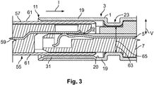
- Fig. 3 in which the signal connector 3 shown in Figs. 1 and 2 is shown in a partially mated state.
- a mating connector 55 is arranged in the receptacle 9.
- Fig. 3 shows the connectors 3 and 55 along a cross sectional cut that extends through a signal contact element 5 parallel with the insertion direction I and the vertical direction V.
- the mating connector 55 is provided with a shielding 57 for electromagnetically shielding signal contact elements 59 of the mating connector 55.
- the mating connector 55 may be formed as a connector 3, in particular the shielding 57 may be formed as a shielding 1 according to the invention. However, in the embodiment shown in Fig. 3 , the shielding 57 of the mating connector 55 is not provided with a guiding protrusion. In the mated state, each signal contact element 5 is electrically connected to a corresponding signal contact element 59 of the mating connector 55.
- the shielding 57 is, as also the shielding 1, formed by shielding walls 61.
- the shielding 57 is preferably formed with a cross-sectional shape (not shown) that corresponds to the trapezoidal shape of the shielding 1.
- the outer side of the shielding 57 abuts the inner side of the shielding 1.
- the shield contact springs 39 apply a contact force F against the shielding 57, thereby holding the same in place.
- the guiding protrusions 31 may abut the shielding 57 and prevent the shielding 57 from movement, in particular from tilting movement along the vertical direction V.
- the guiding protrusion 31 may be necessary for compensating a cross section reduction of the contact carrier 7.
- the whole contact carrier 7 may have a diameter 63 that is smaller than the inner diameter 65 of the shielding 1 in the region of the neck section 23.
- the contact carrier 7 is spaced apart from the shielding wall 19 in the receptacle 9.
- the guiding protrusion 31 may compensate this and may abut the shielding 57 in the mated state. In the mated state, a shielding wall 61 of the mating connector 55 is arranged between the contact carrier 7 and the guiding protrusion 31 without play.
- the shielding wall 61 of the mating connector 55 may directly abut the shielding wall 19 of the shielding 1. However, it may also be possible to provide said shielding wall 19 with at least one further guiding protrusion 31.
- Fig. 4 shows a signal connector 3 with a connector shielding 1.
- the shielding 1 is provided with an overall rectangular shape instead of a trapezoidal shape.
- “vertical" guiding protrusions 31 are omitted.
- the shielding 1 is provided with a nose 67 that protrudes from a plane 20 of the shielding wall 19 along the vertical direction V.
- the nose 67 is intended for preventing a wrongly orientated insertion of the shielding 1 into a connector housing.
- a connector housing (not shown) is preferably provided with a complementary groove into which the nose 67 may be inserted.
- the contact carrier 7 is provided with through-holes 69 that allow the signal contact elements 5 to extend through the through-holes 69 towards a side of the receptacle 9 that is opposite to the nose 67.
- the through-holes 69 allow a movement of the signal contact elements 5 in particular when the connector 3 is mated with a mating connector 55.
- the signal contact elements 5 may then be elastically deflected and dive into the through-holes 69.
- the shielding wall 61 is provided with openings 71 that may receive at least the free ends of the signal contact elements 5 in a mated position.
- the openings 71 are preferably arranged side-by-side along the horizontal direction H and are separated by a web 73 that extends parallel with an insertion direction I of the shielding 57.
- the shielding 57 of the second embodiment may be formed as a shielding 1 according to the invention since it is provided with a receptacle 75 into which the contact carrier 7 of the signal connector 3 may be inserted. Furthermore, the shielding 57 is provided with a guiding protrusion 31.
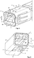
- a first embodiment of the guiding protrusion 31 that is shown in Figs. 5 and 6 is arranged between the web 73 and the forward end 11. In the mated state, as shown in Fig. 6 , the guiding protrusion 31 abuts the contact carrier 7 of the connector 3.
- the guiding protrusion 31 is formed as an elastically deflectable leaf spring 77 that is formed by the web 73.
- the web 73 is only connected to the remaining shielding 57 with one of its ends such that it is movable along the vertical direction V.
- the leaf spring 77 may be pre-bent towards the receptacle 75 such that it is elastically deflected out of said receptacle 75 when the contact carrier 7 is arranged inside the receptacle 75.
- a third embodiment of the guiding protrusion 31 is shown in Fig. 8 .
- the guiding protrusion 31 is formed on the web 73 by a curved section 79 in which the web 73 protrudes into the receptacle 75, thereby forming the guiding protrusion 31.
Landscapes
- Details Of Connecting Devices For Male And Female Coupling (AREA)
- Coupling Device And Connection With Printed Circuit (AREA)
Abstract
Description
- The invention relates to a connector shielding for a connector for transmitting signals, the connector shielding comprising a plurality of shielding walls, wherein the shielding walls form a receptacle for receiving a mating connector, the receptacle being open against an insertion direction at a forward end of the shielding for insertion of the mating connector, and wherein at least two shielding walls are parallel with each other at least in sections in a cross-section perpendicular to the insertion direction. The invention further relates to a signal connector and a pair of mating signal connectors.
- Signal connectors and connector shielding are known in the art. A connector shielding is used for electromagnetically shielding signal contact elements in a connector from influences from outside the connector and also in order to control the impedance of the signal lines to which the signal contact elements belong. In particular in miniaturized signal connectors, for example connectors that have diameters below 10 mm or even below 5 mm, it is important that the shieldings and other parts of the connectors do not get damaged during mating of the connectors. Furthermore, it is important that, in a mated state, the position of the shieldings with respect to each other is well defined.
- It is therefore an object of the invention to provide a connector shielding, a connector and a pair of connectors as mentioned above which facilitate the mating of the connectors, in particular the mating of the shieldings thereof and which allow for a well-defined relative position of two connector shieldings with respect to each other in a mated state.
- According to the invention, this object is achieved for the connector shielding mentioned above, in that at least one shielding wall is provided with at least one guiding protrusion protruding from the shielding wall towards the receptacle. For the signal connector mentioned above, the object is achieved in that the connector is provided with a connector shielding according to the invention. For the pair of connectors, the object is achieved in that at least one connector is a connector according to the invention.
- The at least one guiding protrusion may guide the mating connector, in particular a shielding thereof, during mating the two connectors. It may further protect the shielding wall from which the at least one protrusion protrudes during mating of the connectors, in particular during mating of the two shieldings. Finally, the at least one guiding protrusion may define the position of the two connectors with respect to each other in the mated state, in particular in a direction perpendicular to the insertion direction. The at least one guiding protrusion provides a synergetic effect since the shielding itself may guide a mating connector. Additional guiding means, for example on a connector housing, can be omitted.
- The at least one guiding protrusion may be in contact with the connector shielding or a contact carrier of the mating connector during mating of the connectors and in the fully mated state.
- In the following, further improvements of the invention are described. The additional improvements may be combined independently of each other, depending on whether a particular advantage of a particular improvement is needed in a specific application.
- According to a first advantageous improvement, the connector shielding preferably has, at least in the region of the receptacle, a polygonal cross section, for example a rectangular or trapezoidal cross section. The trapezoidal shape may be used for preventing the insertion of the connector into a housing in a wrong orientation.
- Preferably, the at least one shielding wall has, at a forward end of the connector shielding, at least one run-on slope for guiding the two connectors during mating, wherein the at least one guiding protrusion is located behind the at least run on slope. The run-on slope may facilitate guiding the two connectors into a mating position. Once the forward end of both connectors or of one connector shielding and a part of the other connector has passed at least one of the run-on slopes, the at least one guiding protrusion may continue guiding of the two connectors with respect to each other. In other words, a mating connector is first guided by the run-on slope and afterwards by the at least one guiding protrusion until it reaches the mated position.
- The term "behind" refers to a position farther away from a run-on slope, seen along the insertion direction. Or, in other words, the at least one guiding protrusion may be recessed from the forward end along the insertion direction. The at least one run-on slope may be formed by a chamfered edge of the shielding wall at the forward end. Preferably, several shielding walls are provided with run-on slopes and thereby form a funnel for receiving the shielding of the mating connector or another part of said mating connector. At least a portion of the mating connector may be formed as a wedge in order to interact with the at least one run-on slope and thereby to facilitate the insertion of one connector into the other.
- At least one guiding protrusion may have a rim-shape or rail-shape in order to facilitate the guiding along the insertion direction. Preferably, two guiding protrusions are arranged adjacent and parallel with each other. The two guiding protrusions preferably extend parallel to the insertion direction.
- In order to securely fixate two mated connectors with respect to each other, the connector shielding may be provided with at least one, in particular elastically deflectable, shield contact spring for generating a contact force in a direction towards the receptacle, wherein the at least one guiding protrusion is arranged between the at least one shield contact spring and a forward end of the connector shielding. The at least one shield contact spring may fixate both connectors in a force-fitting manner. The at least one shield contact spring may at least partially protrude towards or into the receptacle for the mating connector. When the mating connector, or a part of the same, is inserted into the receptacle, the at least one shield contact spring may get deflected out of the receptacle and may apply a spring force onto the mating connector.
- The at least one guiding protrusion and the at least one shield contact spring may at least partially overlap along the insertion direction. In other words, the at least one guiding protrusion and the at least one shield contact spring at least partially overlap each other when seen along the insertion direction. The at least one guiding protrusion covers the at least one shield contact spring at least in parts along the insertion direction. The at least one guiding protrusion may thereby protect the at least one shield contact spring, in particular during mating of the two connectors.
- In order to provide a simple but reliable shield contact spring, the at least one shield contact spring is preferably formed as a leaf spring that basically extends parallel with the insertion direction. The at least one shield contact spring is preferably deflectable perpendicular to the insertion direction. More preferably, the at least one shield contact spring extends into the receptacle for a mating connector in a non-deflected state and deflects out of the receptacle in the fully mated state. A free end of the leaf spring may point towards the at least one guiding protrusion.
- In order to overlap with the at least one shield contact spring also when said shield contact spring extends into the receptacle for a mating connector, the at least one guiding protrusion preferably has a recessed portion that is recessed from a plane of the remaining shielding wall into the receptacle.
- The recessed portion may be formed by a straight section between two bends that space said straight section apart from the plane of the remaining shielding wall. The straight section may be parallel with the remaining shielding wall. Preferably, the at least one recessed portion is, along the insertion direction, arranged between the forward end of the shielding and an opening in the shielding wall that opens up a moving space for the at least one shield contact spring. In other words, the at least one recessed portion may have the overall shape of a web that extends perpendicular to the insertion direction.
- The at least one guiding protrusion preferably has the overall shape of a bow, wherein a rear of the bow extends into the receptacle. The rear may form a recessed portion. The bow may bridge the at least two shielding walls that are parallel with each other.
- The connector shielding is preferably provided with at least one further guiding protrusion, in particular at a shielding wall that is different from the shielding wall that has the aforementioned guiding protrusion.
- In order to further facilitate the mating of the two connectors, the connector shielding may be provided with at least two guiding protrusions that are arranged on two sides of the connector shielding which are opposite each other across a receptacle for a mating connector. Preferably, the at least two guiding protrusions are arranged opposite each other across the receptacle. More preferably, the connector shielding is provided with at least one shield contact spring on each side of receptacle, wherein each shield contact spring is arranged behind one guiding protrusion as described above. At least one side of the connector shielding may be provided with at least two shield contact springs, wherein the shield contact springs are arranged side-by-side in a circumferential direction of the connector shielding, and wherein both shield contact springs basically extend parallel with the insertion direction.
- The connector shielding may have at least two openings in a shielding wall for allowing signal contact elements to reach into said openings, in particular during deflection of the contacts, the at least two openings being arranged side by side perpendicular to the insertion direction, wherein at least one guiding protrusion is formed on a web between the at least two openings.
- The at least two openings can be helpful in order to provide a space into which the signal contact elements or the forward ends of the same can be deflected without contacting any of the shielding walls during mating of the two connectors. The web preferably extends parallel with the insertion direction. The at least one guiding protrusion may for example be formed as a protrusion that protrudes from the web. In another preferred embodiment, the web may form a deflectable spring that is provided with the protrusion on its free end.
- In order to securely fixate the connector shielding in a connector housing, the connector shielding is preferably provided with at least one neck section extending in the peripheral surface of the shielding perpendicular to the insertion direction for retaining the connector shielding in the connector housing, wherein the at least one guiding protrusion is arranged between a forward end of the connector shielding and the at least one neck section. The at least one neck section may form a reduction of the cross section of the shielding. The neck section may be formed by a circumferential retention groove.
- The connector shielding may be a stamp-bent part, wherein the at least one guiding protrusion is formed monolithically with at least one of the shielding walls. Preferably, the at least one shield contact spring is also formed monolithically with the at least one guiding protrusion and at least one of the shielding walls. If the connector shielding is provided with a neck section, the groove is preferably also formed monolithically with the aforementioned elements. The shielding walls are preferably electrically interconnected with each other, more preferably, the shielding walls are formed monolithically with each other and the remaining shielding.
- The connector preferably comprises at least one neck section and at least one contact carrier for the at least one signal contact element, the at least one contact carrier extending into the receptacle through the at least one neck section, wherein at least the portion of the contact carrier that extends into the receptacle has a diameter or a cross-section that is equal or smaller than an inner diameter or a cross-section of the neck section. The at least one signal contact element is preferably enclosed or embedded in the at least one contact carrier. The contact carrier may thereby be spaced apart from the shielding wall adjacent to the groove. In other words, a clearing may be formed between the contact carrier and the shielding wall that is larger than the shielding wall of the mating connector that is to be inserted into this clearing.
- The at least one guiding protrusion may in particular in this case form a spacer for spacing the corresponding shielding wall apart from the inserted shielding wall of the mating connector. In the fully mated state, the at least one shielding wall of the mating connector is arranged between the at least one guiding protrusion and the at least one contact carrier. Tilting of the connector shielding with respect to the mating connector may thereby be prevented.
- In a fully mated state, a connector shielding of the mating connector is preferably inserted into the connector shielding of the signal connector or vice versa. From the pair of connectors, both shieldings may be formed by shieldings according to the invention if both shielding shall be provided with at least one guiding protrusion. In the fully mated state, the at least one signal contact element of the connector is preferably electrically connected to a corresponding signal contact element of the mating connector.
- In the following, the invention and its improvements are described in greater detail using exemplary embodiments and with reference to the drawings. As described above, the various features shown in the embodiments may be used independently of each other in specific applications.
- In the following figures, elements having the same function and/or the same structure will be referenced by the same reference signs.
- In the drawings:
- Fig. 1
- shows a first embodiment of a connector with a connector shielding according to the invention in a perspective view;
- Fig. 2
- shows the connector shielding of
Fig. 1 without other part of the connector in a perspective view; - Fig. 3
- shows a cross-sectional view of the connector of
Fig. 1 with an inserted mating connector; - Fig. 4
- shows a second embodiment of a connector with a shielding according to the invention;
- Fig. 5
- shows a connector with a shielding according to the invention that is insertable into the connector of
Fig. 4 ; and -
Figs. 6 to 8 show further embodiments of the connector shown inFig. 5 . - In the following, a first advantageous embodiment of a connector shielding 1 according to the invention is described with respect to
Figs. 1 and 2 . Thereby,Fig. 1 shows the shielding 1 used in asignal connector 3 andFig. 2 shows the connector shielding 1 without any other part of theconnector 3. - The
signal connector 3 comprises a pair ofsignal contact elements 5 that are embedded in acontact carrier 7. Thecontact carrier 7 may be made from a dielectric material. Thecontact carrier 7 carries thesignal contact elements 5. - The
signal contact elements 5 are surrounded by the shielding 1 along a circumferential direction C. The circumferential direction C extends around a longitudinal axis L of the shielding 1 and theconnector 3. Said longitudinal direction L extends parallel to an insertion direction I along which a mating connector (not shown yet) is insertable into theshielding 1. - The shielding 1 opens up a
receptacle 9 for receiving a mating connector. Thereceptacle 9 is open towards aforward end 11 of theshielding 1. Theforward end 11 also forms theforward end 11 of theconnector 3. At arearward end 13, the shielding 1 is provided with acrimp barrel 15 for the connection with acable 17. Preferably, the shielding 1 extends longitudinally from therearward end 13 to theforward end 11 along the longitudinal axis L. - The shielding 1, at least in the region of the
receptacle 9, preferably has a rectangular or trapezoidal cross section. Also other polygonal shapes are possible. In the embodiment shown inFigs 1 and 2 , the cross section has an overall trapezoidal shape. The trapezoidal shape may be used for preventing the insertion of theconnector 3 into a housing in a wrong orientation. - The shielding 1 is composed of a plurality of shielding
walls 19 which are preferably formed monolithically with each other fromsheet material 27 by stamp bending. In other words, the shielding 1 is preferably a stampbent part 21. Each shieldingwall 19 is basically flat and defines aplane 20. - In order to retain the connector shielding 1 in a housing, the shielding 1 is provided with a
neck section 23 that extends through theperipheral surface 25 of the shielding 1 along the circumferential direction C. Theneck section 23 is preferably formed by bending thesheet material 27 before forming the shieldingwalls 19 and closing thereceptacle 9. - The two
signal contact elements 5 are arranged side by side and thereby define a signalcontact element plane 29 that is indicated inFig. 1 . Two of theside walls 19 are parallel with each other and also parallel with thesignal contact plane 29. Thesignal contact plane 29 defines a horizontal direction H that is parallel with theplane 29 and perpendicular to the insertion direction I stop thesignal contact plane 29 further defines a vertical direction V that is perpendicular to thesignal contact plane 29. It should be noted that the terms "horizontal" and" vertical" are chosen only for descriptive reasons. They do not relate to the orientation of the connector in space, but refer to the features of the shielding and the connector and the aforementioned directions. - The two
shielding walls 19 that are not parallel with thesignal contact plane 29 are inclined with respect to each other in order to form the overall trapezoidal shape. - One
shielding wall 19 that is parallel with thesignal contact plane 29 is provided with two guidingprotrusions 31. The shieldingwall 19 with the guidingprotrusions 31 is the shieldingwall 19 inFigs. 1 and 2 that is on the lower side of theshielding 1. The guidingprotrusions 31 extend longitudinally parallel with the insertion direction I and protrude perpendicular to thesignal contact plane 29 into thereceptacle 9. The guidingprotrusions 31 have an overall rim-shape or rail-shape. - The guiding
protrusions 31 can be regarded as "vertical" guidingprotrusion 31 since they may guide a mating connector along the vertical direction V during mating of the connectors. The guidingprotrusion 31 may be formed by punching or pressing the material 27 in order to form the elongated shape that protrudes out of the shieldingwall 19. - The guiding
protrusions 31 are arranged between theforward end 11 and theneck section 23 along the insertion direction I. At theforward end 11, thematerial 27 of the shielding is chamfered or inclined to form an overall funnel-shape in order to facilitate the insertion of a mating connector into thereceptacle 9. Thematerial 27 is therefore provided with a chamfered edge 30 at theforward end 11. - In addition to the "vertical" guiding
protrusions 31, the shielding 1 is provided with two more guidingprotrusions 33. The guidingprotrusions 33 are located at the shieldingwalls 19 that are inclined with respect to each other in order to form the trapezoidal shape. The guidingprotrusion 33 protrude towards each other and into thereceptacle 9. The guidingprotrusions 33 basically protrude in a direction perpendicular to the insertion direction I and perpendicular to the vertical direction V. The guidingprotrusions 33 may be regarded as "horizontal" guidingprotrusions 33 because they may guide a mating connector along the horizontal direction H. - The "horizontal" guiding
protrusion 33 may be formed by bending a strip-like portion ofmaterial 27 such that for each protrusion 33 astraight section 35 and twobent sections 37 are formed. Thestraight section 35 form recess portions 36 of the guidingprotrusion 33. Thebent sections 37 connect thestraight section 35 with the remaining shieldingwall 19. At theforward end 11, each guidingprotrusion 33 is provided with the chamfered edge 30. Each guidingprotrusion 33 has the overall shape of a bow 43, wherein the rear 45 of the bow 43 extends into thereceptacle 9. - As mentioned above, the guiding
protrusions 33 are made from a strip like portions of thematerial 27. The strip-like portions are formed byopenings 41 in thematerial 27 of the shieldingwalls 19 which are arranged behind theprotrusions 33 along the insertion direction I. - The shielding 1 is provided with shield contact springs 39 that are elastically deflectable out of the
receptacle 9. Preferably, eachshield contact spring 39 is formed as a leaf spring 40. In a not-mated state as shown inFigs. 1 and 2 , the shield contact springs 39 extend into thereceptacle 9 and thesprings 39 may get deflected out of thereceptacle 9 when a mating contact is inserted into thereceptacle 9. - The
openings 41 allow the shield contact springs 39 to move freely along the horizontal direction H at least with their free ends 47. Eachshield contact spring 39 has a base 49 at which it is connected with the corresponding shieldingwall 19 and afree end 47 that extends from thebase 49. Eachshield contact spring 39 has an overall elongated shape that extends parallel with the insertion direction I, wherein thebase 49 is located closer to therearward end 13 and thefree end 47 is located closer to theforward end 11. - Into each
opening 41, two shield contact springs 39 extends. The two shield contact springs 39 that are arranged on thesame shielding wall 19 are arranged parallel with each other and adjacent to each other in the vertical direction V. Atotal height 51 of both shield contact springs 39 on thesame shielding wall 19 is preferably larger than aheight 53 of thestraight section 35 of the guidingprotrusion 33. - Along the insertion direction I, the guiding
protrusions 33 at least partially overlap the shield contact springs 39 in order to protect the same when mating the connectors. - Reference is now made to
Fig. 3 , in which thesignal connector 3 shown inFigs. 1 and 2 is shown in a partially mated state. In the partially mated state, amating connector 55 is arranged in thereceptacle 9.Fig. 3 shows theconnectors signal contact element 5 parallel with the insertion direction I and the vertical direction V. - The
mating connector 55 is provided with a shielding 57 for electromagnetically shieldingsignal contact elements 59 of themating connector 55. Themating connector 55 may be formed as aconnector 3, in particular the shielding 57 may be formed as a shielding 1 according to the invention. However, in the embodiment shown inFig. 3 , the shielding 57 of themating connector 55 is not provided with a guiding protrusion. In the mated state, eachsignal contact element 5 is electrically connected to a correspondingsignal contact element 59 of themating connector 55. - The shielding 57 is, as also the shielding 1, formed by shielding
walls 61. The shielding 57 is preferably formed with a cross-sectional shape (not shown) that corresponds to the trapezoidal shape of theshielding 1. In the mated state, the outer side of the shielding 57 abuts the inner side of theshielding 1. Furthermore, the shield contact springs 39 apply a contact force F against the shielding 57, thereby holding the same in place. The guidingprotrusions 31 may abut the shielding 57 and prevent the shielding 57 from movement, in particular from tilting movement along the vertical direction V. - In particular in the case that the shielding 1 is provided with a
neck section 23, the guidingprotrusion 31 may be necessary for compensating a cross section reduction of thecontact carrier 7. In other words, in order to insert thecontact carrier 7 into the shielding 1 during manufacturing of thesignal connector 3, thewhole contact carrier 7 may have adiameter 63 that is smaller than theinner diameter 65 of the shielding 1 in the region of theneck section 23. However, due to this requirement, thecontact carrier 7 is spaced apart from the shieldingwall 19 in thereceptacle 9. The guidingprotrusion 31 may compensate this and may abut the shielding 57 in the mated state. In the mated state, a shieldingwall 61 of themating connector 55 is arranged between thecontact carrier 7 and the guidingprotrusion 31 without play. - On the opposite side of the
receptacle 9, the shieldingwall 61 of themating connector 55 may directly abut the shieldingwall 19 of theshielding 1. However, it may also be possible to provide said shieldingwall 19 with at least one further guidingprotrusion 31. - In the following, additional embodiments of the
connector 3 and themating connector 55 are described with respect toFigs. 4 to 8 . For the sake of brevity, only the differences to the aforementioned embodiment are described in detail. -
Fig. 4 shows asignal connector 3 with aconnector shielding 1. In contrast to the aforementioned embodiment, the shielding 1 is provided with an overall rectangular shape instead of a trapezoidal shape. Furthermore, "vertical" guidingprotrusions 31 are omitted. Finally, at theforward end 11, the shielding 1 is provided with anose 67 that protrudes from aplane 20 of the shieldingwall 19 along the vertical direction V. Thenose 67 is intended for preventing a wrongly orientated insertion of the shielding 1 into a connector housing. Such a connector housing (not shown) is preferably provided with a complementary groove into which thenose 67 may be inserted. - The
contact carrier 7 is provided with through-holes 69 that allow thesignal contact elements 5 to extend through the through-holes 69 towards a side of thereceptacle 9 that is opposite to thenose 67. The through-holes 69 allow a movement of thesignal contact elements 5 in particular when theconnector 3 is mated with amating connector 55. Thesignal contact elements 5 may then be elastically deflected and dive into the through-holes 69. - In order to prevent the
signal contact elements 5 from getting into contact with the shieldingwall 61 of the shielding 57, the shieldingwall 61 is provided withopenings 71 that may receive at least the free ends of thesignal contact elements 5 in a mated position. - The
openings 71 are preferably arranged side-by-side along the horizontal direction H and are separated by aweb 73 that extends parallel with an insertion direction I of the shielding 57. It should be noted that the shielding 57 of the second embodiment may be formed as a shielding 1 according to the invention since it is provided with areceptacle 75 into which thecontact carrier 7 of thesignal connector 3 may be inserted. Furthermore, the shielding 57 is provided with a guidingprotrusion 31. - A first embodiment of the guiding
protrusion 31 that is shown inFigs. 5 and6 is arranged between theweb 73 and theforward end 11. In the mated state, as shown inFig. 6 , the guidingprotrusion 31 abuts thecontact carrier 7 of theconnector 3. - In a further embodiment of the guiding
protrusion 31 of the second embodiment of themating connector 55, the guidingprotrusion 31 is formed as an elasticallydeflectable leaf spring 77 that is formed by theweb 73. In other words, theweb 73 is only connected to the remaining shielding 57 with one of its ends such that it is movable along the vertical direction V. Theleaf spring 77 may be pre-bent towards thereceptacle 75 such that it is elastically deflected out of saidreceptacle 75 when thecontact carrier 7 is arranged inside thereceptacle 75. - Finally, a third embodiment of the guiding
protrusion 31 is shown inFig. 8 . The guidingprotrusion 31 is formed on theweb 73 by acurved section 79 in which theweb 73 protrudes into thereceptacle 75, thereby forming the guidingprotrusion 31. -
- 1
- Connector shielding
- 3
- Signal connector
- 5
- Signal contact element
- 7
- Contact carrier
- 9
- Receptacle
- 11
- Forward end
- 13
- Rearward end
- 15
- Crimp barrel
- 17
- Cable
- 19
- Shielding wall
- 20
- Plane
- 21
- Stamp bent part
- 23
- Neck section
- 25
- Peripheral surface
- 27
- Sheet material
- 29
- Signal contact plane
- 30
- Chamfered edge
- 31
- Guiding protrusion
- 33
- Guiding protrusion
- 35
- Straight section
- 36
- Recessed portion
- 37
- Bent section
- 39
- Shield contact spring
- 40
- Leaf spring
- 41
- Opening
- 43
- Bow
- 45
- Rear
- 47
- Free end
- 49
- Base
- 51
- Height
- 53
- Height
- 55
- Mating Connector
- 57
- Shielding
- 59
- Signal contact element
- 61
- Shielding wall
- 63
- Diameter
- 65
- Inner diameter
- 67
- Nose
- 69
- Through-hole
- 71
- Opening
- 73
- Web
- 75
- Receptacle
- 77
- Leaf spring
- 79
- Curved section
- C
- Circumferential direction
- F
- Contact force
- H
- Horizontal direction
- I
- Insertion direction
- L
- Longitudinal axis
- V
- Vertical direction
Claims (15)
- Connector shielding (1, 57) for a connector (3, 55) for transmitting signals, the connector shielding (1, 57) comprising a plurality of shielding walls (19, 61), wherein the shielding walls (19, 61) form a receptacle (9) for receiving a mating connector (3, 55), the receptacle (9) being open against an insertion direction (I) at a forward end (11) of the shielding (1, 57) for insertion of the mating connector (3, 55), and wherein at least two shielding walls (19, 61) are parallel with each other at least in sections in a cross-section perpendicular to the insertion direction (I), characterized in that at least one shielding wall (19, 61) is provided with at least one guiding protrusion (31, 33) protruding from the shielding wall (19, 61) towards the receptacle (9).
- Connector shielding (1, 57) according to claim 1, characterized in that the connector shielding (1, 57) is provided with at least one shield contact spring (39) for generating contact force (F) in a direction towards the receptacle (9), wherein the at least one guiding protrusion (31, 33) is arranged between the at least one shield contact spring (39) and a forward end (11) of the connector shielding (1, 57).
- Connector shielding (1, 57) according to claim 2, characterized in that the at least one guiding protrusion (31, 33) and the at least one shield contact spring (39) at least partially overlap along the insertion direction (I).
- Connector shielding (1, 57) according to claim 2 or 3, characterized in that the at least one shield contact spring (39) is formed as a leaf spring (40) that basically extends parallel with the insertion direction (I).
- Connector shielding (1, 57) according to any of claims 2 to 4, characterized in that the at least one guiding protrusion (31, 33) has a recessed portion (36) that is recessed from a plane (20) of the remaining shielding wall (19, 61) towards the receptacle (9).
- Connector shielding (1, 57) according to claim 5, characterized in that the at least one guiding protrusion (31, 33) has the overall shape of a bow (43), wherein a rear (45) of the bow (43) extends towards the receptacle (9).
- Connector shielding (1, 57) according to any of claims 2 to 6, characterized in that the connector shielding (1, 57) is provided with at least one further guiding protrusion (31, 33).
- Connector shielding (1, 57) according to claim 7, characterized in that at least two guiding protrusions (31 ,33) are arranged on two sides of the connector shielding (1, 57) which are opposite each other across the receptacle (9).
- Connector shielding (1, 57) according to any of claims 1 to 8, characterized in that the connector shielding (1, 57) has at least two openings (71) in a shielding wall (19, 61) for allowing signal contact elements (5, 59) to reach into said openings (71), the at least two openings (71) being arranged side by side perpendicular to the insertion direction (I), wherein at least one guiding protrusion (31, 33) is formed on a web (73) between the at least two openings (71).
- Connector shielding (1, 57) according to any of claims 1 to 9, characterized in that the connector shielding (1, 57) is provided with at least one neck section (23) extending in the peripheral surface (25) of the shielding (1, 57) perpendicular to the insertion direction (I) for retaining the connector shielding (1, 57) in a connector housing, wherein the at least one guiding protrusion (31, 33) is arranged between a forward end (11) of the connector shielding (1, 57) and the at least one neck section (23).
- Connector shielding (1, 57) according to any of claims 1 to 10, characterized in that the connector shielding (1, 57) is a stamp-bent part (21), wherein the at least one guiding protrusion (31, 33) is formed monolithically with at least one of the shielding walls (19, 61).
- Connector (3, 55) comprising a connector shielding (1, 57) and at least one signal contact element (5, 59) that is at least partially surrounded by the connector shielding (1, 57), characterized in that the connector shielding (1, 57) is formed according to any of claims 1 to 11.
- Connector (3, 55) according to claim 12, characterized in that the connector (3, 55) comprises at least one neck section (23) and at least one contact carrier (7) for the at least one signal contact element (5, 59), the at least one contact carrier (7) extending into the receptacle (9) through the at least one neck section (23), wherein at least the portion of the contact carrier (7) that extends into the receptacle (9) has a diameter (63) that is equal or smaller than an inner diameter (65) of the neck section (23).
- Connector assembly comprising a pair of mating connectors (3, 55), characterized in that at least one connector (3, 55) is formed according to claim 12 or 13.
- Connector assembly according to claim 14, characterized in that the at least one shielding wall (19, 61) of the mating connector (3, 55) is arranged between the at least one guiding protrusion (31, 33) and the at least one contact carrier (7) in the fully mated state.
Priority Applications (5)
| Application Number | Priority Date | Filing Date | Title |
|---|---|---|---|
| EP19193936.2A EP3787130A1 (en) | 2019-08-27 | 2019-08-27 | Connector shielding with a guiding protrusion |
| JP2020139034A JP7626528B2 (en) | 2019-08-27 | 2020-08-20 | Connector shield with guide projection |
| KR1020200106967A KR102763337B1 (en) | 2019-08-27 | 2020-08-25 | Connector shielding with a guiding protrusion |
| CN202010869837.5A CN112448239B (en) | 2019-08-27 | 2020-08-26 | Connector shield with guide projections |
| US17/004,647 US11888266B2 (en) | 2019-08-27 | 2020-08-27 | Connector shielding with a guiding protrusion |
Applications Claiming Priority (1)
| Application Number | Priority Date | Filing Date | Title |
|---|---|---|---|
| EP19193936.2A EP3787130A1 (en) | 2019-08-27 | 2019-08-27 | Connector shielding with a guiding protrusion |
Publications (1)
| Publication Number | Publication Date |
|---|---|
| EP3787130A1 true EP3787130A1 (en) | 2021-03-03 |
Family
ID=67777107
Family Applications (1)
| Application Number | Title | Priority Date | Filing Date |
|---|---|---|---|
| EP19193936.2A Pending EP3787130A1 (en) | 2019-08-27 | 2019-08-27 | Connector shielding with a guiding protrusion |
Country Status (5)
| Country | Link |
|---|---|
| US (1) | US11888266B2 (en) |
| EP (1) | EP3787130A1 (en) |
| JP (1) | JP7626528B2 (en) |
| KR (1) | KR102763337B1 (en) |
| CN (1) | CN112448239B (en) |
Families Citing this family (2)
| Publication number | Priority date | Publication date | Assignee | Title |
|---|---|---|---|---|
| JP7670579B2 (en) | 2021-08-20 | 2025-04-30 | 日本航空電子工業株式会社 | Connector Assembly |
| US20250266648A1 (en) * | 2024-02-21 | 2025-08-21 | Te Connectivity Solutions Gmbh | Shield Contact System |
Citations (4)
| Publication number | Priority date | Publication date | Assignee | Title |
|---|---|---|---|---|
| US20060189211A1 (en) * | 2005-02-23 | 2006-08-24 | Molex Incorporated | Connector and guide placement member |
| EP2613410A1 (en) * | 2010-09-03 | 2013-07-10 | Yazaki Corporation | Structure for preventing improper insertion of connector |
| US9667000B1 (en) * | 2016-06-09 | 2017-05-30 | Delphi Technologies, Inc. | Radio frequency coaxial connector assembly and method of manufacturing same |
| US20180212376A1 (en) * | 2017-01-25 | 2018-07-26 | Lotes Co., Ltd | Electrical connector |
Family Cites Families (12)
| Publication number | Priority date | Publication date | Assignee | Title |
|---|---|---|---|---|
| CN201238121Y (en) * | 2008-07-30 | 2009-05-13 | 实盈电子(东莞)有限公司 | Network communication connector |
| CN102341970B (en) * | 2009-01-20 | 2014-04-30 | 莫列斯公司 | Plug connectors with external EMI shielding |
| US7695319B1 (en) * | 2009-06-16 | 2010-04-13 | Cheng Uei Precision Industry Co., Ltd. | Electrical connector having a shield case with elastic locking pieces |
| TW201214884A (en) * | 2010-09-27 | 2012-04-01 | Chou-Hsien Tsai | Electrical receptacle |
| DE102011056715A1 (en) * | 2011-12-20 | 2013-06-20 | Telegärtner Karl Gärtner GmbH | Cable connecting device |
| CN204809558U (en) * | 2015-05-29 | 2015-11-25 | 富士康(昆山)电脑接插件有限公司 | Electric connector |
| US9722362B2 (en) * | 2015-10-23 | 2017-08-01 | T-Conn Precision Corporation | Electrical connector with improved shielding shell |
| DE102016104992A1 (en) * | 2016-03-17 | 2017-09-21 | Te Connectivity Germany Gmbh | Connector for a watertight connector, waterproof connector and pre-assembled cable |
| EP3306756B1 (en) * | 2016-10-07 | 2020-04-15 | TE Connectivity Germany GmbH | Plug connector |
| CN206532925U (en) | 2016-11-22 | 2017-09-29 | 番禺得意精密电子工业有限公司 | Electric connector |
| JP2019040690A (en) * | 2017-08-23 | 2019-03-14 | タイコエレクトロニクスジャパン合同会社 | Shield connector |
| US10797449B2 (en) * | 2019-03-05 | 2020-10-06 | Niceconn Technology Co., Ltd. | Connector having one-piece housing |
-
2019
- 2019-08-27 EP EP19193936.2A patent/EP3787130A1/en active Pending
-
2020
- 2020-08-20 JP JP2020139034A patent/JP7626528B2/en active Active
- 2020-08-25 KR KR1020200106967A patent/KR102763337B1/en active Active
- 2020-08-26 CN CN202010869837.5A patent/CN112448239B/en active Active
- 2020-08-27 US US17/004,647 patent/US11888266B2/en active Active
Patent Citations (4)
| Publication number | Priority date | Publication date | Assignee | Title |
|---|---|---|---|---|
| US20060189211A1 (en) * | 2005-02-23 | 2006-08-24 | Molex Incorporated | Connector and guide placement member |
| EP2613410A1 (en) * | 2010-09-03 | 2013-07-10 | Yazaki Corporation | Structure for preventing improper insertion of connector |
| US9667000B1 (en) * | 2016-06-09 | 2017-05-30 | Delphi Technologies, Inc. | Radio frequency coaxial connector assembly and method of manufacturing same |
| US20180212376A1 (en) * | 2017-01-25 | 2018-07-26 | Lotes Co., Ltd | Electrical connector |
Also Published As
| Publication number | Publication date |
|---|---|
| US20210098942A1 (en) | 2021-04-01 |
| CN112448239B (en) | 2025-10-21 |
| KR102763337B1 (en) | 2025-02-04 |
| CN112448239A (en) | 2021-03-05 |
| KR20210025496A (en) | 2021-03-09 |
| US11888266B2 (en) | 2024-01-30 |
| JP7626528B2 (en) | 2025-02-04 |
| JP2021034380A (en) | 2021-03-01 |
Similar Documents
| Publication | Publication Date | Title |
|---|---|---|
| US11450979B2 (en) | Receptacle connector with alignment features | |
| CA2727981C (en) | Electrical connector with a compliant cable strain relief element | |
| US10320102B2 (en) | Receptacle connector with contact assembly | |
| US10283913B2 (en) | Electrical connector with a shielding plate | |
| US8152566B1 (en) | Electrical connector with resilient arm configured in fixed ended beam manner formed on metal shell | |
| US6386928B2 (en) | Electrical contact | |
| US7621772B1 (en) | Electrical connector with a compliant cable strain relief element | |
| US7229329B2 (en) | Female terminal fitting | |
| US10608383B2 (en) | Electrical connector shield with gap shielding | |
| US6709298B2 (en) | Insulator coring and contact configuration to prevent pin stubbing in the throat of tuning fork socket connector contacts | |
| US11888266B2 (en) | Connector shielding with a guiding protrusion | |
| KR20030044875A (en) | Connector having a shielding shell provided with a locking portion | |
| KR20230024355A (en) | modular plug connector | |
| EP0806813B1 (en) | Electrical connector having terminals with improved retention means | |
| US7556530B2 (en) | Connector in which defective electrical connection between a plurality of shell components is suppressed | |
| US11183797B2 (en) | Plug connector system | |
| US20040147146A1 (en) | Receptacle connector with separable ground fingers | |
| KR101520927B1 (en) | Terminal | |
| US12166309B2 (en) | Connector capable of preventing damage to a seal member | |
| HK1153574B (en) | Electrical connector with a compliant cable strain relief element |
Legal Events
| Date | Code | Title | Description |
|---|---|---|---|
| PUAI | Public reference made under article 153(3) epc to a published international application that has entered the european phase |
Free format text: ORIGINAL CODE: 0009012 |
|
| STAA | Information on the status of an ep patent application or granted ep patent |
Free format text: STATUS: THE APPLICATION HAS BEEN PUBLISHED |
|
| AK | Designated contracting states |
Kind code of ref document: A1 Designated state(s): AL AT BE BG CH CY CZ DE DK EE ES FI FR GB GR HR HU IE IS IT LI LT LU LV MC MK MT NL NO PL PT RO RS SE SI SK SM TR |
|
| AX | Request for extension of the european patent |
Extension state: BA ME |
|
| STAA | Information on the status of an ep patent application or granted ep patent |
Free format text: STATUS: REQUEST FOR EXAMINATION WAS MADE |
|
| 17P | Request for examination filed |
Effective date: 20210830 |
|
| RBV | Designated contracting states (corrected) |
Designated state(s): AL AT BE BG CH CY CZ DE DK EE ES FI FR GB GR HR HU IE IS IT LI LT LU LV MC MK MT NL NO PL PT RO RS SE SI SK SM TR |
|
| STAA | Information on the status of an ep patent application or granted ep patent |
Free format text: STATUS: EXAMINATION IS IN PROGRESS |
|
| 17Q | First examination report despatched |
Effective date: 20220920 |