EP3786772B1 - Electronic device and operation method thereof - Google Patents
Electronic device and operation method thereof Download PDFInfo
- Publication number
- EP3786772B1 EP3786772B1 EP20188959.9A EP20188959A EP3786772B1 EP 3786772 B1 EP3786772 B1 EP 3786772B1 EP 20188959 A EP20188959 A EP 20188959A EP 3786772 B1 EP3786772 B1 EP 3786772B1
- Authority
- EP
- European Patent Office
- Prior art keywords
- area
- touch input
- writing
- predefined
- electronic device
- Prior art date
- Legal status (The legal status is an assumption and is not a legal conclusion. Google has not performed a legal analysis and makes no representation as to the accuracy of the status listed.)
- Active
Links
Images











Classifications
-
- G—PHYSICS
- G06—COMPUTING OR CALCULATING; COUNTING
- G06F—ELECTRIC DIGITAL DATA PROCESSING
- G06F3/00—Input arrangements for transferring data to be processed into a form capable of being handled by the computer; Output arrangements for transferring data from processing unit to output unit, e.g. interface arrangements
- G06F3/01—Input arrangements or combined input and output arrangements for interaction between user and computer
- G06F3/048—Interaction techniques based on graphical user interfaces [GUI]
- G06F3/0487—Interaction techniques based on graphical user interfaces [GUI] using specific features provided by the input device, e.g. functions controlled by the rotation of a mouse with dual sensing arrangements, or of the nature of the input device, e.g. tap gestures based on pressure sensed by a digitiser
- G06F3/0488—Interaction techniques based on graphical user interfaces [GUI] using specific features provided by the input device, e.g. functions controlled by the rotation of a mouse with dual sensing arrangements, or of the nature of the input device, e.g. tap gestures based on pressure sensed by a digitiser using a touch-screen or digitiser, e.g. input of commands through traced gestures
- G06F3/04883—Interaction techniques based on graphical user interfaces [GUI] using specific features provided by the input device, e.g. functions controlled by the rotation of a mouse with dual sensing arrangements, or of the nature of the input device, e.g. tap gestures based on pressure sensed by a digitiser using a touch-screen or digitiser, e.g. input of commands through traced gestures for inputting data by handwriting, e.g. gesture or text
-
- G—PHYSICS
- G06—COMPUTING OR CALCULATING; COUNTING
- G06F—ELECTRIC DIGITAL DATA PROCESSING
- G06F3/00—Input arrangements for transferring data to be processed into a form capable of being handled by the computer; Output arrangements for transferring data from processing unit to output unit, e.g. interface arrangements
- G06F3/01—Input arrangements or combined input and output arrangements for interaction between user and computer
- G06F3/048—Interaction techniques based on graphical user interfaces [GUI]
- G06F3/0487—Interaction techniques based on graphical user interfaces [GUI] using specific features provided by the input device, e.g. functions controlled by the rotation of a mouse with dual sensing arrangements, or of the nature of the input device, e.g. tap gestures based on pressure sensed by a digitiser
- G06F3/0488—Interaction techniques based on graphical user interfaces [GUI] using specific features provided by the input device, e.g. functions controlled by the rotation of a mouse with dual sensing arrangements, or of the nature of the input device, e.g. tap gestures based on pressure sensed by a digitiser using a touch-screen or digitiser, e.g. input of commands through traced gestures
-
- G—PHYSICS
- G06—COMPUTING OR CALCULATING; COUNTING
- G06F—ELECTRIC DIGITAL DATA PROCESSING
- G06F3/00—Input arrangements for transferring data to be processed into a form capable of being handled by the computer; Output arrangements for transferring data from processing unit to output unit, e.g. interface arrangements
- G06F3/01—Input arrangements or combined input and output arrangements for interaction between user and computer
- G06F3/03—Arrangements for converting the position or the displacement of a member into a coded form
- G06F3/041—Digitisers, e.g. for touch screens or touch pads, characterised by the transducing means
- G06F3/0416—Control or interface arrangements specially adapted for digitisers
-
- G—PHYSICS
- G06—COMPUTING OR CALCULATING; COUNTING
- G06F—ELECTRIC DIGITAL DATA PROCESSING
- G06F3/00—Input arrangements for transferring data to be processed into a form capable of being handled by the computer; Output arrangements for transferring data from processing unit to output unit, e.g. interface arrangements
- G06F3/01—Input arrangements or combined input and output arrangements for interaction between user and computer
- G06F3/048—Interaction techniques based on graphical user interfaces [GUI]
- G06F3/0481—Interaction techniques based on graphical user interfaces [GUI] based on specific properties of the displayed interaction object or a metaphor-based environment, e.g. interaction with desktop elements like windows or icons, or assisted by a cursor's changing behaviour or appearance
- G06F3/0483—Interaction with page-structured environments, e.g. book metaphor
-
- G—PHYSICS
- G06—COMPUTING OR CALCULATING; COUNTING
- G06F—ELECTRIC DIGITAL DATA PROCESSING
- G06F3/00—Input arrangements for transferring data to be processed into a form capable of being handled by the computer; Output arrangements for transferring data from processing unit to output unit, e.g. interface arrangements
- G06F3/01—Input arrangements or combined input and output arrangements for interaction between user and computer
- G06F3/048—Interaction techniques based on graphical user interfaces [GUI]
- G06F3/0484—Interaction techniques based on graphical user interfaces [GUI] for the control of specific functions or operations, e.g. selecting or manipulating an object, an image or a displayed text element, setting a parameter value or selecting a range
-
- G—PHYSICS
- G06—COMPUTING OR CALCULATING; COUNTING
- G06F—ELECTRIC DIGITAL DATA PROCESSING
- G06F3/00—Input arrangements for transferring data to be processed into a form capable of being handled by the computer; Output arrangements for transferring data from processing unit to output unit, e.g. interface arrangements
- G06F3/01—Input arrangements or combined input and output arrangements for interaction between user and computer
- G06F3/048—Interaction techniques based on graphical user interfaces [GUI]
- G06F3/0484—Interaction techniques based on graphical user interfaces [GUI] for the control of specific functions or operations, e.g. selecting or manipulating an object, an image or a displayed text element, setting a parameter value or selecting a range
- G06F3/04842—Selection of displayed objects or displayed text elements
-
- G—PHYSICS
- G06—COMPUTING OR CALCULATING; COUNTING
- G06F—ELECTRIC DIGITAL DATA PROCESSING
- G06F3/00—Input arrangements for transferring data to be processed into a form capable of being handled by the computer; Output arrangements for transferring data from processing unit to output unit, e.g. interface arrangements
- G06F3/01—Input arrangements or combined input and output arrangements for interaction between user and computer
- G06F3/048—Interaction techniques based on graphical user interfaces [GUI]
- G06F3/0484—Interaction techniques based on graphical user interfaces [GUI] for the control of specific functions or operations, e.g. selecting or manipulating an object, an image or a displayed text element, setting a parameter value or selecting a range
- G06F3/04845—Interaction techniques based on graphical user interfaces [GUI] for the control of specific functions or operations, e.g. selecting or manipulating an object, an image or a displayed text element, setting a parameter value or selecting a range for image manipulation, e.g. dragging, rotation, expansion or change of colour
-
- G—PHYSICS
- G06—COMPUTING OR CALCULATING; COUNTING
- G06F—ELECTRIC DIGITAL DATA PROCESSING
- G06F3/00—Input arrangements for transferring data to be processed into a form capable of being handled by the computer; Output arrangements for transferring data from processing unit to output unit, e.g. interface arrangements
- G06F3/01—Input arrangements or combined input and output arrangements for interaction between user and computer
- G06F3/048—Interaction techniques based on graphical user interfaces [GUI]
- G06F3/0487—Interaction techniques based on graphical user interfaces [GUI] using specific features provided by the input device, e.g. functions controlled by the rotation of a mouse with dual sensing arrangements, or of the nature of the input device, e.g. tap gestures based on pressure sensed by a digitiser
- G06F3/0488—Interaction techniques based on graphical user interfaces [GUI] using specific features provided by the input device, e.g. functions controlled by the rotation of a mouse with dual sensing arrangements, or of the nature of the input device, e.g. tap gestures based on pressure sensed by a digitiser using a touch-screen or digitiser, e.g. input of commands through traced gestures
- G06F3/04886—Interaction techniques based on graphical user interfaces [GUI] using specific features provided by the input device, e.g. functions controlled by the rotation of a mouse with dual sensing arrangements, or of the nature of the input device, e.g. tap gestures based on pressure sensed by a digitiser using a touch-screen or digitiser, e.g. input of commands through traced gestures by partitioning the display area of the touch-screen or the surface of the digitising tablet into independently controllable areas, e.g. virtual keyboards or menus
-
- G—PHYSICS
- G06—COMPUTING OR CALCULATING; COUNTING
- G06F—ELECTRIC DIGITAL DATA PROCESSING
- G06F40/00—Handling natural language data
- G06F40/10—Text processing
- G06F40/103—Formatting, i.e. changing of presentation of documents
- G06F40/114—Pagination
-
- G—PHYSICS
- G06—COMPUTING OR CALCULATING; COUNTING
- G06F—ELECTRIC DIGITAL DATA PROCESSING
- G06F40/00—Handling natural language data
- G06F40/10—Text processing
- G06F40/12—Use of codes for handling textual entities
- G06F40/163—Handling of whitespace
-
- G—PHYSICS
- G06—COMPUTING OR CALCULATING; COUNTING
- G06F—ELECTRIC DIGITAL DATA PROCESSING
- G06F40/00—Handling natural language data
- G06F40/10—Text processing
- G06F40/166—Editing, e.g. inserting or deleting
- G06F40/171—Editing, e.g. inserting or deleting by use of digital ink
-
- G—PHYSICS
- G06—COMPUTING OR CALCULATING; COUNTING
- G06F—ELECTRIC DIGITAL DATA PROCESSING
- G06F2203/00—Indexing scheme relating to G06F3/00 - G06F3/048
- G06F2203/048—Indexing scheme relating to G06F3/048
- G06F2203/04806—Zoom, i.e. interaction techniques or interactors for controlling the zooming operation
Definitions
- Embodiments of the disclosure relate to an electronic device and an operation method thereof, and more particularly, to an electronic device having an electronic board function and an operation method thereof.
- EP 2 685 365 A2 , US 2019/220133 A1 , CN 102 446 055 A , and US 2019/114022 A1 describe examples of the related art.
- an electronic board device having a handwriting input function in addition to a content display function in the display devices, is widely used.
- the electronic board device is generally shared by many people. For example, a user may give a presentation to other users by using the electronic board device. Also, due to properties of the electronic board device, a size of a document (for example, a page), which is a target of a writing input, may be fixed. However, when the space of a page becomes insufficient as the user writes using the electronic board device, the user cannot expand the fixed size of the page due to the properties of the electronic board device and may be inconvenient for the user.
- a document for example, a page
- Various embodiments of the disclosure provide an electronic device having an electronic board function and facilitate expansion of a writing input interface (area), and an operation method of the electronic device.
- an electronic device including: a display; a touch input interface; a memory storing at least one instruction; and a processor configured to execute the at least one instruction stored in the memory to: display a writing area in a display area of the display; detect a predefined touch input in the writing area; and based on detecting the predefined touch input, reduce the writing area, display the reduced writing area in at least first part of the display area and provide an extended area in at least second part of the display area, the extended area being configured to receive a writing input continuing from the reduced writing area.
- the processor may be further configured to execute the at least one instruction to: provide a user interface for confirming whether the extended area is to be provided in the display area in response to the detection of the predefined touch input; and based on receiving a user input in the user interface, provide the extended area.
- the processor may be further configured to execute the at least one instruction to: based on the detection of the predefined touch input, reduce the writing area included in a current page among a plurality of pages in a document, the current page being an execution target of a current touch input, and provide the extended area by applying the extended area to the current page.
- an operation method of an electronic device including: displaying a writing area in a display area of a display of the electronic device; detecting a predefined touch input in the writing area; and based on detecting the predefined touch input, reducing the writing area, displaying the reduced writing area in at least first part of the display area and providing an extended area in at least second part of the display area, the extended area being configured to receive a writing input continuing from the reduced writing area.
- the operation method may further include: based on the detection of the predefined touch input, reducing the writing area in each page among a plurality of pages included in a document, wherein a first page among the plurality of pages is an execution target of a current touch input, and providing the extended area by applying the extended area to the plurality of pages in the document.
- FIG. 1 is a reference view illustrating an electronic device having an electronic board function according to an embodiment.
- a document file which is a target of a writing input in the electronic device 100 may be referred to as a roll.
- the roll may be a file including a plurality of connected pages.
- a roll may include, for example, 1 to 20 pages. The number of pages of a roll may depend on a system status.
- a roll may be used in two modes, such as a horizontal mode and a vertical mode.
- a roll may be used in the vertical mode.
- pages are connected vertically in a direction of their longer sides. Accordingly, a user may use new pages by scrolling pages down.
- the user may want to continuously write in the horizontal direction. In this case, the user may not be able to continue writing in the horizontal direction because horizontal and vertical lengths of each page have fixed sizes.
- a roll When the electronic device 100 is positioned to show a horizontal screen, a roll may be used in the horizontal mode.
- pages are connected horizontally in such a way to follow one after another at their shorter sides. Accordingly, a user may use new pages by scrolling pages to the left or right.
- the user may want to continuously write in the vertical direction. In this case, the user may not be able to continue writing in the vertical direction because horizontal and vertical lengths of each page have fixed sizes.
- the user may not find a space to make a writing input on a screen of the electronic device 100.
- the user may make a predefined touch input 60 in an edge area 50.
- the electronic device 100 may determine the predefined touch input 60 as the user's intention for extending an area for a writing input, reduce the writing area 40, and provide an extended area 70.
- writing context included in the writing area 40 is "SAMSUNG FliP”
- the electronic device 100 may reduce the writing area 40 including the writing content "SAMSUNG Flip,” and provide the extended area 70 in a space generated when the writing area 40 is reduced.
- the user may make an additional writing input following the writing input by using the extended area 70.
- the electronic device 100 may easily provide the user with an additional space for a writing input without requiring the user's menu control or button control, and provide the user with an experience of making a writing input without interruption regardless of a space of a writing area.
- the electronic device 100 may recognize the predefined touch input as a trigger for providing the extended area 70.
- the predefined touch input may be one of various types of touch inputs. For example, when a touch input continues for a predefined time or more within the edge area 50, when a touch input is made two times in a predefined time within the edge area 50, or when pressure of a touch input exceeds a threshold value within the edge area 50, the electronic device 100 may detect the touch input as the predefined touch input.
- the above-mentioned touch inputs are only examples, and the electronic device 100 may use other types of touch inputs.
- the edge area 50 as a location in the writing area 40 from which the predefined touch input is detected may be an example, and the predefined touch input may be detected from any other location in the writing area 40.
- the electronic device 100 may automatically provide a user interface for confirming the user's intention with respect to the extended area 70 before providing the extended area 70, and then provide the extended area 70 in response to the user's input to the user interface. For example, when the electronic device 100 detects the predefined touch input, the electronic device 100 may output a pop-up window for inquiring the user about whether he/she wants the extended area 70, and provide the extended area 70 after receiving the user's confirmation to the pop-up window. As such, by inquiring the user's intention before providing an extended area, the electronic device 100 may be prevented from providing an extended area unintended by the user.
- the electronic device 100 may reduce a writing area in response to a detection of the predefined touch input, and provide an extended area by using a space generated when the writing area is reduced.
- a range of the reduced writing area may be determined according to a setting of the electronic device 100 or a user's setting.
- the reduced writing area may be a writing area corresponding to the entirety of a document which is an execution target of a current touch input, and in this case, the extended area may be applied to the entire document and provided.
- the reduced writing area may be a writing area included in a current page displayed on a display in a document which is an execution target of a current touch input, and in this case, the extended area may be applied to the current page and provided.
- the reduced writing area may be an object area related to a location of a touch input, and in this case, the extended area may be applied to the object area and provided.
- the electronic device 100 is configured to determine a size of the extended area according to a parameter value corresponding to the detected touch input.
- the parameter value corresponding to the touch input may include at least one of a duration time of the touch input, pressure corresponding to the touch input, or the number of touch input.
- the electronic device 100 may determine the size of the extended area in proportion to the duration time of the touch input.
- the electronic device 100 may increase the size of the extended area based on the number of touch inputs being received within a predetermined time frame.
- the electronic device 100 may determine the size of the extended area in proportion to pressure of the touch input.
- the electronic device 100 may enable a user to conveniently adjust the size of the extended area without having to navigate through a control menu or press additional buttons.
- the electronic device 100 may identify a location of a detected touch input, define a reference point that is relative to the determined location of the touch input, reduce a writing area based on the reference point, and provide an extended area in a space generated in a display area when the writing area is reduced.
- the predefined touch input 60 may be made on a right edge area (e.g., edge area 50 of FIG. 1 ), and a reference point that is relative to the predefined touch input 60 may be at a location corresponding to a left edge area. Because the writing area 40 is reduced based on the reference point, the writing area 40 may move to the left, and thus a space may be generated to the right of the writing area 40.
- the extended area 70 may be provided to the right of the writing area 40 as shown in FIG. 1 .
- the edge area 50 may be positioned on at least one of a right edge, a left edge, an upper edge, or a lower edge of the writing area 40.
- FIG. 3 is a block diagram of an electronic device according to an embodiment.
- the electronic device 100 may include a display 110, a memory 120, a processor 130, and a user input interface 190.
- the electronic device 100 is not limited thereto, and may be implemented with more or less components than the components shown in FIG. 3 .
- the display 110 may display data that is processed in the electronic device 100.
- the display 110 may be used as an input device, as well as an output device.
- the display 110 may include at least one of a liquid crystal display (LCD), a thin film transistor-liquid crystal display (TFT-LCD), an organic light-emitting diode (OLED) display, a flexible display, a 3Dimensional (3D) display, or an electrophoretic display.
- LCD liquid crystal display
- TFT-LCD thin film transistor-liquid crystal display
- OLED organic light-emitting diode
- flexible display a flexible display
- 3Dimensional (3D) display or an electrophoretic display.
- the user input interface 190 which is an interface for receiving a user input, may receive a touch input by using a touch sensitive device.
- the user input may include a touch input made by a user's finger, a touch input made by a user's palm, an input made by an electronic pen, etc.
- the user input may include an input made by a general brush. In this case, the user may have an experience as though he/she draws a picture with a brush on a canvas.
- the user input interface 190 may include a touch sensitive device for measuring pressure of a detected touch input.
- the memory 120 may store programs for processing and controlling of the processor 130.
- the memory 120 may store data input to the electronic device 100 and data that is to be output from the electronic device 100.
- the memory 120 may include at least one type of storage medium of a flash memory type, a hard disk type, a multimedia card micro type, card type memory (for example, secure digital (SD) memory or extreme digital (XD) memory), random access memory (RAM), static random access memory (SRAM), read-only memory (ROM), electrically erasable programmable read-only memory (EEPROM), programmable read-only memory (PROM), magnetic memory, a magnetic disk, or an optical disk.
- SD secure digital
- XD extreme digital
- RAM random access memory
- SRAM static random access memory
- ROM read-only memory
- EEPROM electrically erasable programmable read-only memory
- PROM programmable read-only memory
- magnetic memory a magnetic disk, or an optical disk.
- the memory 120 may include at least one instruction for performing an extended area providing at least one function disclosed herein.
- the processor 130 may control overall operations of the electronic device 100.
- the processor 130 may execute at least one instruction stored in the memory 120 to control the display 110 and perform functions of the electronic device 100 shown in FIGS. 1 to 16 .
- the processor 130 may execute at least one instruction stored in the memory 120 to detect a predefined touch input in a writing area displayed on a pre-defined display area, reduce the writing area in response to the detection of the predefined touch input, and provide an extended area for a writing input.
- the predefined touch input may include at least one of a touch input maintained for a predefined time or more within the writing area, a touch input corresponding to a double tap made within the writing area, or a touch input of which pressure exceeds a threshold value in the writing area.
- the processor 130 may execute at least one instruction stored in the memory 120 to provide a user interface for confirming a user's intention with respect to an extended area in response to a detection of a predefined touch input, and provide the extended area in response to the user's input reacting to the user interface.
- the processor 130 may execute at least one instruction stored in the memory 120 to reduce the entirety of a document which is an execution target of a current touch input in response to a detection of a predefined touch input, apply an extended area to the entire document, and provide the extended area.
- the processor 130 may execute at least one instruction stored in the memory 120 to reduce a writing area included in a current page displayed on the display 110 in a document which is an execution target of a current touch input, in response to a detection of a predefined touch input, apply an extended area to the current page, and provide the extended area.
- the processor 130 may execute at least one instruction stored in the memory 120 to reduce an object area related to a location of a touch input, in response to a detection of a predefined touch input, apply an extended area to the object area, and provide the extended area.
Landscapes
- Engineering & Computer Science (AREA)
- Theoretical Computer Science (AREA)
- General Engineering & Computer Science (AREA)
- Physics & Mathematics (AREA)
- General Physics & Mathematics (AREA)
- Human Computer Interaction (AREA)
- Health & Medical Sciences (AREA)
- Artificial Intelligence (AREA)
- Audiology, Speech & Language Pathology (AREA)
- Computational Linguistics (AREA)
- General Health & Medical Sciences (AREA)
- User Interface Of Digital Computer (AREA)
Description
- Embodiments of the disclosure relate to an electronic device and an operation method thereof, and more particularly, to an electronic device having an electronic board function and an operation method thereof.
EP 2 685 365 A2US 2019/220133 A1 ,CN 102 446 055 A , andUS 2019/114022 A1 describe examples of the related art. - With the development of electronic technologies, various kinds of electronic products have been developed and distributed. In particular, various display devices, such as TVs, mobile phones, personal computers (PCs), laptop computers, personal digital assistants (PDAs), and the like, are widely used in homes.
- Also, an electronic board device having a handwriting input function, in addition to a content display function in the display devices, is widely used.
- The electronic board device is generally shared by many people. For example, a user may give a presentation to other users by using the electronic board device. Also, due to properties of the electronic board device, a size of a document (for example, a page), which is a target of a writing input, may be fixed. However, when the space of a page becomes insufficient as the user writes using the electronic board device, the user cannot expand the fixed size of the page due to the properties of the electronic board device and may be inconvenient for the user.
- Various embodiments of the disclosure provide an electronic device having an electronic board function and facilitate expansion of a writing input interface (area), and an operation method of the electronic device.
- Additional aspects, features, and advantages will be set forth in part in the description which follows and, in part, will be apparent from the description, or may be learned by practice of the embodiments of the disclosure.
- According to an embodiment, there is provided an electronic device including: a display; a touch input interface; a memory storing at least one instruction; and a processor configured to execute the at least one instruction stored in the memory to: display a writing area in a display area of the display; detect a predefined touch input in the writing area; and based on detecting the predefined touch input, reduce the writing area, display the reduced writing area in at least first part of the display area and provide an extended area in at least second part of the display area, the extended area being configured to receive a writing input continuing from the reduced writing area.
- The predefined touch input includes at least one of a touch input for a first predefined time or more in the writing area, a touch input made repeatedly for a second predefined time in the writing area, or a touch input of which pressure exceeds a threshold value in the writing area. The processor is further configured to execute the at least one instruction to: identify a parameter value corresponding to the predefined touch input, the parameter value including at least one of a duration time of the predefined touch input, pressure corresponding to the predefined touch input, or a number of times of the predefined touch input; and determine a size of the extended area according to the parameter value.
- The processor may be further configured to execute the at least one instruction to: provide a user interface for confirming whether the extended area is to be provided in the display area in response to the detection of the predefined touch input; and based on receiving a user input in the user interface, provide the extended area.
- The processor may be further configured to execute the at least one instruction to: based on the detection of the predefined touch input, reduce the writing area in each page among a plurality of pages included in a document, wherein a first page among the plurality of pages is an execution target of a current touch input, and provide the extended area by applying the extended area to the plurality of pages in the document.
- The processor may be further configured to execute the at least one instruction to: based on the detection of the predefined touch input, reduce the writing area included in a current page among a plurality of pages in a document, the current page being an execution target of a current touch input, and provide the extended area by applying the extended area to the current page.
- The processor may be further configured to execute the at least one instruction to, based on the detection of the predefined touch input, reduce an object area related to a location of the predefined touch input in the writing area, and provide the extended area by applying the extended area to the object area, where the object area is one of an area including an object related to the predefined touch input, connected to the predefined touch input by handwriting, or being within a certain distance from the predefined touch input.
- The processor may be further configured to execute the at least one instruction to: identify a location of the predefined touch input; determine a reference point with respect to the location of the predefined touch input; and reduce the writing area based on the reference point and provide the extended area at a location where a space is generated in the display area.
- The processor may be further configured to execute the at least one instruction to detect the predefined touch input in an edge area of the writing area, where the edge area is positioned on at least one of a right edge, a left edge, an upper edge, or a lower edge of the writing area.
- According to an embodiment, there is provided an operation method of an electronic device, the operation method including: displaying a writing area in a display area of a display of the electronic device; detecting a predefined touch input in the writing area; and based on detecting the predefined touch input, reducing the writing area, displaying the reduced writing area in at least first part of the display area and providing an extended area in at least second part of the display area, the extended area being configured to receive a writing input continuing from the reduced writing area.
- The predefined touch input includes at least one of a touch input for a first predefined time or more in the writing area, a touch input made repeatedly for a second predefined time in the writing area, or a touch input of which pressure exceeds a threshold value in the writing area. The operation method further includes: identifying a parameter value corresponding to the predefined touch input, the parameter value including at least one of a duration time of the predefined touch input, a pressure corresponding to the predefined touch input, or a number of times of the predefined touch input; and determining a size of the extended area according to the parameter value.
- The operation method may further include: providing a user interface for confirming whether the extended area is to be provided in the display area in response to the detection of the predefined touch input; and based on receiving a user input in the user interface, providing the extended area.
- The operation method may further include: based on the detection of the predefined touch input, reducing the writing area in each page among a plurality of pages included in a document, wherein a first page among the plurality of pages is an execution target of a current touch input, and providing the extended area by applying the extended area to the plurality of pages in the document.
- The operation method may further include: based on the detection of the predefined touch input, reducing the writing area included in a current page among a plurality of pages in a document, the current page being an execution target of a current touch input, and providing the extended area by applying the extended area to the current page.
- The operation method may further include, based on the detection of the predefined touch input, reducing an object area related to a location of the predefined touch input in the writing area, and providing the extended area by applying the extended area to the object area.
- The operation method may further include: identifying a location of the detected predefined touch input; determining a reference point with respect to the location of the predefined touch input; and reducing the writing area based on the reference point and providing the extended area at a location where a space is generated in the display area.
- The operation method may further include detecting the predefined touch input in an edge area of the writing area, where the edge area is positioned on at least one of a right edge, a left edge, an upper edge, or a lower edge of the writing area.
- According to an embodiment, there is provided a non-transitory computer-readable recording medium storing a program for performing an operation method of an electronic device, by a processor, the operation method including: displaying a writing area in a display area of a display of the electronic device; detecting a predefined touch input in the writing area; and based on detecting the predefined touch input, reducing the writing area, displaying the reduced writing area in at least first part of the display area and providing an extended area in at least second part of the display area, the extended area being configured to receive a writing input continuing from the reduced writing area. The operation method further includes: identifying a parameter value corresponding to the predefined touch input, the parameter value including at least one of a duration time of the predefined touch input, a pressure corresponding to the predefined touch input, or a number of times of the predefined touch input; and determining a size of the extended area according to the parameter value.
- The above and other aspects, features, and advantages of certain embodiments of the disclosure will be more apparent from the following description taken in conjunction with the accompanying drawings, in which:
-
FIG. 1 is a reference view illustrating an electronic device having an electronic board function according to an embodiment; -
FIG. 2 is a schematic diagram illustrating examples of rolls that are used in a vertical mode and a horizontal mode according to an embodiment; -
FIG. 3 is a block diagram of an electronic device according to an embodiment; -
FIG. 4 is a block diagram illustrating a configuration of an electronic device according to an embodiment; -
FIG. 5 is a flowchart of an operation method of an electronic device according to an embodiment; -
FIG. 6 is a schematic diagram illustrating an edge area for receiving a predefined touch input according to an embodiment; -
FIG. 7 is a schematic diagram illustrating an example of a method for providing an extended area according to an embodiment; -
FIG. 8 is a schematic diagram illustrating an example of a method of confirming a user's intention when an extended area is provided according to an embodiment; -
FIG. 9A is a reference view illustrating a method of providing an extended area according to an embodiment; -
FIG. 9B is a reference view illustrating a method of providing an extended area according to an embodiment; -
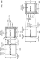
FIG. 10A is a reference view illustrating a method of reducing a writing area and positioning the reduced writing area according to an embodiment; -
FIG. 10B is a reference view illustrating a method of reducing a writing area and positioning the reduced writing area according to an embodiment; -
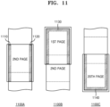
FIG. 11 is a reference view illustrating locations to which an extended area may be provided according to an embodiment; -
FIG. 12 is a reference view illustrating an example of reducing a writing area in units of rolls according to an embodiment; -
FIG. 13 is a reference view illustrating an example of reducing a writing area in units of pages according to an embodiment; -
FIG. 14 is a reference view illustrating an example of reducing a writing area in units of objects according to an embodiment; -
FIG. 15 is a reference view illustrating an extended area in an example of writing using a brush according to an embodiment of; and -
FIG. 16 is a reference view illustrating a scenario for providing an extended area according to an embodiment. - Terms used herein will be briefly described, and the disclosure will be described in detail.
- Although widely used terms were selected as terminology used in the disclosure, they may vary according to intentions of one of ordinary skill in the art, judicial precedents, the advent of new technologies, and the like. Terms arbitrarily selected in the disclosure may also be used in a specific case.
- Throughout the disclosure, the expression "at least one of a, b or c" indicates only a, only b, only c, both a and b, both a and c, both b and c, all of a, b, and c, or variations thereof.
- It will be understood that when a certain part "includes" a certain component, the part does not exclude another component but can further include another component, unless the context clearly indicates otherwise. As used herein, the terms "portion", "module", etc. refers to a unit that can perform at least one function or operation, and may be implemented as hardware, software, or a combination of hardware and software.
- Hereinafter, embodiments will be described in detail with reference to the accompanying drawings so that the disclosure may be readily implemented by one of ordinary skill in the technical field to which the disclosure pertains. However, the disclosure can be implemented in various different forms, and is not limited to the embodiments described herein. Also, in the drawings, portions irrelevant to the description are not shown in order to more clearly describe the embodiments, and throughout the disclosure, similar components are assigned like reference numerals.
- The term "user" means a person who controls the functions or operations of an image display device using a controller, and may include a viewer, a manager, or an installation engineer.
-
FIG. 1 is a reference view illustrating an electronic device having an electronic board function according to an embodiment. - Referring to
FIG. 1 , anelectronic device 100 having an electronic board function may perform various operations. For example, a user may make a handwriting input on theelectronic device 100 with his/her finger or apen 10, connect theelectronic device 100 toexternal devices external devices external devices - A document file which is a target of a writing input in the
electronic device 100 may be referred to as a roll. The roll may be a file including a plurality of connected pages. A roll may include, for example, 1 to 20 pages. The number of pages of a roll may depend on a system status. A roll may be used in two modes, such as a horizontal mode and a vertical mode. -
FIG. 2 is a schematic diagram illustrating examples of rolls that are used in a vertical mode and a horizontal mode according to an embodiment. - Referring to
FIG. 2 , when theelectronic device 100 is positioned to show a vertical screen, a roll may be used in the vertical mode. When the roll is used in the vertical mode, pages are connected vertically in a direction of their longer sides. Accordingly, a user may use new pages by scrolling pages down. However, there may be a case in which, when a user uses a roll in the vertical mode and writes in a horizontal direction of a page until arriving at anend 210 of a screen, the user may want to continuously write in the horizontal direction. In this case, the user may not be able to continue writing in the horizontal direction because horizontal and vertical lengths of each page have fixed sizes. - When the
electronic device 100 is positioned to show a horizontal screen, a roll may be used in the horizontal mode. When the roll is used in the horizontal mode, pages are connected horizontally in such a way to follow one after another at their shorter sides. Accordingly, a user may use new pages by scrolling pages to the left or right. However, there may be a case in which, when a user uses a roll in the horizontal mode and writes in a vertical direction of a page until arriving at anend 220 of a screen, the user may want to continuously write in the vertical direction. In this case, the user may not be able to continue writing in the vertical direction because horizontal and vertical lengths of each page have fixed sizes. - Accordingly, embodiments of the disclosure provide the
electronic device 100 capable of contextually recognizing, when a user makes a writing input on theelectronic device 100, that an area extension is required to provide an extended area, thereby enabling the user to extend a size-fixed page. - Referring back to
FIG. 1 , when the user makes a writing input on awriting area 40 by using theelectronic device 100, the user may not find a space to make a writing input on a screen of theelectronic device 100. In this case, the user may make apredefined touch input 60 in anedge area 50. Then, theelectronic device 100 may determine thepredefined touch input 60 as the user's intention for extending an area for a writing input, reduce thewriting area 40, and provide anextended area 70. InFIG. 1 , because writing context included in thewriting area 40 is "SAMSUNG FliP," theelectronic device 100 may reduce thewriting area 40 including the writing content "SAMSUNG Flip," and provide the extendedarea 70 in a space generated when thewriting area 40 is reduced. When theextended area 70 is provided, the user may make an additional writing input following the writing input by using the extendedarea 70. In this way, by providing an extended area by a user's simple touch input, theelectronic device 100 may easily provide the user with an additional space for a writing input without requiring the user's menu control or button control, and provide the user with an experience of making a writing input without interruption regardless of a space of a writing area. - According to an embodiment, when the
electronic device 100 detects the predefined touch input within theedge area 50, theelectronic device 100 may recognize the predefined touch input as a trigger for providing theextended area 70. The predefined touch input may be one of various types of touch inputs. For example, when a touch input continues for a predefined time or more within theedge area 50, when a touch input is made two times in a predefined time within theedge area 50, or when pressure of a touch input exceeds a threshold value within theedge area 50, theelectronic device 100 may detect the touch input as the predefined touch input. However, the above-mentioned touch inputs are only examples, and theelectronic device 100 may use other types of touch inputs. - Also, the
edge area 50 as a location in thewriting area 40 from which the predefined touch input is detected may be an example, and the predefined touch input may be detected from any other location in thewriting area 40. - According to an embodiment, after the
electronic device 100 detects the predefined touch input, theelectronic device 100 may automatically provide a user interface for confirming the user's intention with respect to the extendedarea 70 before providing theextended area 70, and then provide the extendedarea 70 in response to the user's input to the user interface. For example, when theelectronic device 100 detects the predefined touch input, theelectronic device 100 may output a pop-up window for inquiring the user about whether he/she wants the extendedarea 70, and provide the extendedarea 70 after receiving the user's confirmation to the pop-up window. As such, by inquiring the user's intention before providing an extended area, theelectronic device 100 may be prevented from providing an extended area unintended by the user. - According to an embodiment, the
electronic device 100 may reduce a writing area in response to a detection of the predefined touch input, and provide an extended area by using a space generated when the writing area is reduced. A range of the reduced writing area may be determined according to a setting of theelectronic device 100 or a user's setting. For example, the reduced writing area may be a writing area corresponding to the entirety of a document which is an execution target of a current touch input, and in this case, the extended area may be applied to the entire document and provided. For example, the reduced writing area may be a writing area included in a current page displayed on a display in a document which is an execution target of a current touch input, and in this case, the extended area may be applied to the current page and provided. For example, the reduced writing area may be an object area related to a location of a touch input, and in this case, the extended area may be applied to the object area and provided. - According to an embodiment, the
electronic device 100 is configured to determine a size of the extended area according to a parameter value corresponding to the detected touch input. For example, the parameter value corresponding to the touch input may include at least one of a duration time of the touch input, pressure corresponding to the touch input, or the number of touch input. For example, theelectronic device 100 may determine the size of the extended area in proportion to the duration time of the touch input. As another example, theelectronic device 100 may increase the size of the extended area based on the number of touch inputs being received within a predetermined time frame. As yet another example, theelectronic device 100 may determine the size of the extended area in proportion to pressure of the touch input. As such, by adjusting a size of an extended area according to a parameter value corresponding to a touch input, theelectronic device 100 may enable a user to conveniently adjust the size of the extended area without having to navigate through a control menu or press additional buttons. - According to an embodiment, the
electronic device 100 may identify a location of a detected touch input, define a reference point that is relative to the determined location of the touch input, reduce a writing area based on the reference point, and provide an extended area in a space generated in a display area when the writing area is reduced. For example, referring toFIG. 1 , thepredefined touch input 60 may be made on a right edge area (e.g.,edge area 50 ofFIG. 1 ), and a reference point that is relative to thepredefined touch input 60 may be at a location corresponding to a left edge area. Because thewriting area 40 is reduced based on the reference point, the writingarea 40 may move to the left, and thus a space may be generated to the right of thewriting area 40. Accordingly, theextended area 70 may be provided to the right of thewriting area 40 as shown inFIG. 1 . According to various embodiments, theedge area 50 may be positioned on at least one of a right edge, a left edge, an upper edge, or a lower edge of thewriting area 40. -
FIG. 3 is a block diagram of an electronic device according to an embodiment. - Referring to
FIG. 3 , theelectronic device 100 may include adisplay 110, amemory 120, aprocessor 130, and auser input interface 190. However, theelectronic device 100 is not limited thereto, and may be implemented with more or less components than the components shown inFIG. 3 . - The
display 110 may display data that is processed in theelectronic device 100. When thedisplay 110 is implemented as a touch screen, thedisplay 110 may be used as an input device, as well as an output device. For example, thedisplay 110 may include at least one of a liquid crystal display (LCD), a thin film transistor-liquid crystal display (TFT-LCD), an organic light-emitting diode (OLED) display, a flexible display, a 3Dimensional (3D) display, or an electrophoretic display. - The
user input interface 190, which is an interface for receiving a user input, may receive a touch input by using a touch sensitive device. The user input may include a touch input made by a user's finger, a touch input made by a user's palm, an input made by an electronic pen, etc. Also, the user input may include an input made by a general brush. In this case, the user may have an experience as though he/she draws a picture with a brush on a canvas. In addition, theuser input interface 190 may include a touch sensitive device for measuring pressure of a detected touch input. - The
memory 120 may store programs for processing and controlling of theprocessor 130. Thememory 120 may store data input to theelectronic device 100 and data that is to be output from theelectronic device 100. - The
memory 120 may include at least one type of storage medium of a flash memory type, a hard disk type, a multimedia card micro type, card type memory (for example, secure digital (SD) memory or extreme digital (XD) memory), random access memory (RAM), static random access memory (SRAM), read-only memory (ROM), electrically erasable programmable read-only memory (EEPROM), programmable read-only memory (PROM), magnetic memory, a magnetic disk, or an optical disk. - The
memory 120 may include at least one instruction for performing an extended area providing at least one function disclosed herein. - The
processor 130 may control overall operations of theelectronic device 100. For example, theprocessor 130 may execute at least one instruction stored in thememory 120 to control thedisplay 110 and perform functions of theelectronic device 100 shown inFIGS. 1 to 16 . - According to an embodiment, the
processor 130 may execute at least one instruction stored in thememory 120 to detect a predefined touch input in a writing area displayed on a pre-defined display area, reduce the writing area in response to the detection of the predefined touch input, and provide an extended area for a writing input. - The predefined touch input may include at least one of a touch input maintained for a predefined time or more within the writing area, a touch input corresponding to a double tap made within the writing area, or a touch input of which pressure exceeds a threshold value in the writing area.
- According to an embodiment, the
processor 130 may execute at least one instruction stored in thememory 120 to provide a user interface for confirming a user's intention with respect to an extended area in response to a detection of a predefined touch input, and provide the extended area in response to the user's input reacting to the user interface. - According to an embodiment, the
processor 130 may execute at least one instruction stored in thememory 120 to reduce the entirety of a document which is an execution target of a current touch input in response to a detection of a predefined touch input, apply an extended area to the entire document, and provide the extended area. - According to an embodiment, the
processor 130 may execute at least one instruction stored in thememory 120 to reduce a writing area included in a current page displayed on thedisplay 110 in a document which is an execution target of a current touch input, in response to a detection of a predefined touch input, apply an extended area to the current page, and provide the extended area. - The
processor 130 may execute at least one instruction stored in thememory 120 to reduce an object area related to a location of a touch input, in response to a detection of a predefined touch input, apply an extended area to the object area, and provide the extended area. - According to an embodiment, the
processor 130 is configured to execute at least one instruction stored in thememory 120 to identify a parameter value corresponding to a detected touch input and determine a size of an extended area according to the parameter value. The parameter value corresponding to the touch input includes at least one of a duration time of the touch input, pressure corresponding to the touch input, or the number of times which the touch input is made. - Furthermore, the
processor 130 may execute at least one instruction stored in thememory 120 to identify a location of a detected touch input, define a reference point that is relative to the determined location of the touch input, reduce a writing area based on the reference point, and provide an extended area at a location where a space is generated in the writing area when the writing area is reduced. An edge area may be positioned on at least one of a right edge, a left edge, an upper edge, or a lower edge of the writing area. -
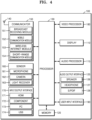
FIG. 4 is a block diagram showing a configuration of an electronic device according to an embodiment. - As shown in
FIG. 4 , theelectronic device 100 may further include avideo processor 180, anaudio processor 115, anaudio output interface 125, atuner 140, acommunicator 150, asensor 160, and an input/output interface 170, in addition to thedisplay 110, thememory 120, theprocessor 130, and theuser input interface 190. - Descriptions overlapping with those given above about the
display 110, thememory 120, theprocessor 130, and theuser input interface 190 with reference toFIG. 3 will be omitted in the following descriptions with reference toFIG. 4 . - The
tuner 140 may amplify, mix, or resonate a broadcasting signal received in a wired or wireless manner to tune and select a frequency of a channel at which theelectronic device 100 is to receive the broadcasting signal from among a plurality of radio wave components. The broadcasting signal may include audio, video, and additional information (for example, electronic program guide (EPG)). - The
communicator 150 may connect theelectronic device 100 to an external device (for example, an audio device, a mobile device, etc.) by a control of theprocessor 130. Theprocessor 130 may transmit/receive content to/from an external device connected through thecommunicator 150, download an application from the external device, or perform web browsing. - The
communicator 150 may include at least one module to enable wireless communications between theelectronic device 100 and a wireless communication system or between theelectronic device 100 and a network on which another electronic device is located. For example, thecommunicator 150 may include abroadcast receiving module 151, amobile communication module 152, awireless internet module 153, and a short-range communication module 154. Thecommunicator 150 is also referred to as a transmitter/receiver. - The
broadcast receiving module 151 may receive a broadcast signal and/or broadcast-related information from an external broadcast management server through a broadcast channel. The broadcast signal may include a TV broadcast signal, a radio broadcast signal, a data broadcast signal, and a broadcast signal resulting from combining a TV broadcast signal or a radio broadcast signal with a data broadcast signal. - The
mobile communication module 152 may transmit/receive wireless signals to/from at least one of a base station, an external terminal, or a server on a mobile communication network. The wireless signal may include a voice call signal, a video call signal or various formats of data according to transmission/reception of text/multimedia messages. - The
wireless internet module 153 may be a module for wireless internet connections, and installed inside or outside theelectronic device 100. As wireless internet technology, wireless LAN (WLAN), Wireless-Fidelity (Wi-Fi), World Interoperability for Microwave Access (Wimax), High Speed Downlink Packet Access (HSDPA), etc. may be used. Through thewireless internet module 153, theelectronic device 100 may establish a Wi-Fi connection to another device. For example, theprocessor 130 may communicate with at least one AP 300 through thewireless internet module 153. - The short-
range communication module 154 may be a module for short-range communication. As short-range communication technology, Bluetooth, Radio Frequency Identification (RFID), Infrared Data Association (IrDA), Ultra Wideband (UWB), Zigbee, etc. may be used. - The
sensor 160 may sense a user's voice, a user's image, or a user's interaction, and may include amicrophone 161, acamera 162, and alight receiver 163. - The
microphone 161 may receive a voice uttered by a user. Themicrophone 161 may convert the received voice into an electrical signal and output the electrical signal to thecontroller 130. - The
camera 162 may receive an image (for example, successive frames) corresponding to a user's motion including a gesture in a camera recognition range. - The
light receiver 163 may receive an optical signal (including a control signal) transmitted from a remote controller. Thelight receiver 163 may receive an optical signal corresponding to a user input (for example, a touch, pressing, a touch gesture, a voice, or a motion) from the remote controller. A control signal may be extracted from the received optical signal by a control of theprocessor 130. - The input/
output interface 170 may receive video (for example, a moving image, etc.), audio (for example, a voice, music, etc.), and additional information (for example, EPG, etc.) from an outside of theelectronic device 100 by a control of theprocessor 130. The input/output interface 170 may include one or a combination of a high-definition multimedia interface (HDMI)port 171, acomponent jack 172, aPC port 173, and aUSB port 174. - The
video processor 180 may process image data that is to be displayed on thedisplay 110, and perform various image processing operations on the image data, such as decoding, rendering, scaling, noise filtering, frame-rate conversion, and resolution conversion. - The
display 110 may display video included in a broadcasting signal received through thetuner 140 on a screen by a control of theprocessor 130. Also, thedisplay 110 may display content (for example, a moving image) received through thecommunicator 150 or the input/output interface 170. Thedisplay 110 may output an image stored in thememory 120 by a control of theprocessor 130. - When the
display 110 and a touch pad form a layer structure to be configured as a touch screen, thedisplay 110 may be used as an input device, as well as an output device. Thedisplay 110 may include at least one of a liquid crystal display (LCD), a thin film transistor-liquid crystal display (TFT-LCD), an organic light-emitting diode (OLED) display, a flexible display, a 3dimensional (3D) display, or an electrophoretic display. - The
audio processor 115 may process audio data. Theaudio processor 115 may perform various processing on the audio data, such as decoding, amplification, noise filtering, etc. - The
audio output interface 125 may output audio included in a broadcasting signal received through thetuner 140, audio input through thecommunicator 150 or the inputter/outputter 170, and audio stored in thememory 120, by the control of theprocessor 130. Theaudio output interface 125 may include at least one of aspeaker 126, aheadphone output terminal 127, or a Sony/Philips Digital Interface (S/PDIF)output terminal 128. - The
user input interface 190 may enable a user to input data for controlling theelectronic device 100. Theuser input interface 190 may include a touch inputter for receiving touch inputs. For example, theuser input interface 190 may be a key pad, a dome switch, a touch pad (a capacitive type, a resistive type, an infrared beam type, a surface acoustic wave type, an integral strain gauge type, a piezo effect type, etc.), a jog wheel, a jog switch, etc.. However, theuser input interface 190 is not limited thereto. - The
memory 120 may store programs for processing and control of theprocessor 130, and store data input to theelectronic device 100 and data to be output from theelectronic device 100. - The
processor 130 may perform functions of controlling overall operations of theelectronic device 100 and signal flow between the internal components of theelectronic device 100 to process data. When a user's input is received or a condition set in advance and stored is satisfied, theprocessor 130 may execute Operating System (OS) and various applications stored in thememory 120. Also, theprocessor 130 may execute at least one instruction to implement a function for providing an extended area in a display area, stored in thememory 120. - The block diagrams of the
electronic device 100 shown inFIGS. 3 and4 are example embodiments of the disclosure. Some of the components of the block diagrams may be integrated or omitted, or other components may be removed or added, according to an actual implementation of theelectronic device 100. For example, two or more of the components may be integrated into one component, or one component may be subdivided into two or more components, as necessary. Also, a function that is performed in each block is only provided to describe the embodiments, and detailed operations or devices therefor should not be considered as limiting the scope of the disclosure. -
FIG. 5 is a flowchart of an operation method of an electronic device according to an embodiment. - Referring to
FIG. 5 , in operation 510, theelectronic device 100 may detect a predefined touch input made in an edge area of a writing area displayed on a display through a touch inputter. - The edge area may include a right edge area, a left edge area, a upper edge area, and a lower edge area corresponding to edges of the writing area displayed on the display, However, the predefined touch input is not limited to an input made in the edge area of the writing area, and the
electronic device 100 may detect the predefined touch input made at any other location of the writing area. - The predefined touch input may be a touch input maintained without interruption for a predefined time or more in the edge area, a touch input made repeatedly for a short time, a touch input of which pressure exceeds a threshold value, etc.
- In
operation 520, theelectronic device 100 may reduce a size of the writing area in response to the detection of the predefined touch input, and provide an extended area extended from the writing area to allow a writing input. - When the
electronic device 100 detects the predefined touch input in the edge area, theelectronic device 100 may recognize the predefined touch input as a user's intention for adding an extended area, and perform an operation for providing an extended area. - The
electronic device 100 may determine a range of the reduced writing area to be one of various ranges. For example, theelectronic device 100 may reduce the entire of the corresponding roll, a writing area included in a current page, or an object area related to a touch input. - The
electronic device 100 is configured to determine a size of the extended area according to a parameter value of the predefined touch input, for example, in proportion to a magnitude of the parameter value. For example, theelectronic device 100 may determine a size of the extended area based on parameter values, such as a duration of a touch input, a number of touch inputs made repeatedly, or pressure of a touch input. Specifically, for example, the longer the period of the user's touch input, the larger the extended area. As another example, the greater the number of touch inputs, the larger the extended area. As yet another example, the greater the pressure of the user's touch input, the larger the extended area. - According to an embodiment, the
electronic device 100 may identify a location of a detected touch input, define a reference point that is relative to the determined location of the touch input, reduce a writing area based on the reference point, and provide an extended area at a location where a space is generated in a display area when the writing area is reduced. -
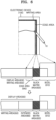
FIG. 6 is a reference view illustrating an edge area for receiving a predefined touch input according to an embodiment. - Referring to
FIG. 6 , abezel 610 may be positioned along edges of a display panel of theelectronic device 100, and ablack matrix area 620 may be provided close to thebezel 610. The remaining area of the display panel except for theblack matrix area 620 may be adisplay area 630 that may be used as a writing area. - That is, the display panel may define the
display area 630 as the writing area. In thedisplay area 630 defined in the display panel, a writing area for a writing input may be displayed. For example, when the writing area is initially used, awriting area 650 may be displayed in theentire display area 630. - When a predefined touch input is detected, the
electronic device 100 may provide an extended area 660. That is, when theelectronic device 100 receives a predefined touch input, theelectronic device 100 may reduce thewriting area 650, and provide the extended area 660 that continues from the reducedwriting area 650, thereby enabling additional writing input in an area of thedisplay 630 excluding the reducedwriting area 650. - In an edge of the
writing area 650, anedge area 640 may be provided to receive the predefined touch input. - A size of the
edge area 640 may be determined appropriately according to a system configuration. When theelectronic device 100 receives the predefined touch input made in theedge area 640, theelectronic device 100 may use the predefined touch input as a trigger signal for providing the extended area 660. - The
edge area 640 may be provided at any location of thewriting area 630. However, when theedge area 640 is positioned at an edge of thewriting area 630, it may be possible to prevent the extended area 660 from being provided against the user's intention. For example, when the predefined touch input is a long press, the user may unintentionally input a long press in a center part of thewriting area 650 while making a writing input in the center part of the writing area. In this case, when theelectronic device 100 provides the extended area 660, the user may be experience inconvenience due to an abrupt reduction in size of writing content or a provision of the extended area 660 against the user's intention. Accordingly, by providing an edge area for receiving a predefined touch input in a portion of edges of a writing area and providing an extended area when a user makes the predefined touch input in the edge area provided in an edge of the writing area, an extended area providing function may be more stably implemented. However, providing an edge area in a portion of edges of a writing area is only an example, and the edge area may be provided at any other location of the writing area according to implementation. - The
electronic device 100 may provide an extended area in response to a detection of a predefined touch input in an edge area of a writing area displayed on a display of the electronic device. The predefined touch input as a trigger signal for providing an extended area may be one of various types of inputs, designated by theelectronic device 100. - For example, the predefined touch input may include a long press which is a touch input maintained for a predefined time at a certain location of the edge area. For example, when a touch input signal is maintained without interruption for a predefined time or more at a certain location of the edge area, the
electronic device 100 may detect the touch input signal as the predefined touch input. - For example, the predefined touch input may include a touch input that is continuously sensed in a predefined short time. For example, the predefined touch input may include a double tap corresponding to two touch inputs made successively for a short time in the edge area. However, the two touch inputs may be an example, and the number of touch inputs made successively may be three or four. That is, the number of touch inputs made successively may be appropriately determined.
- For example, the predefined touch input may include a case in which pressure of a touch input sensed at a certain location in the edge area exceeds a threshold value. For example, when the touch sensitive display is capable of sensing pressure, a touch input which is made in the edge area and of which pressure exceeds a threshold value may be used as the predefined touch input.
- Also, the predefined touch input may be an input corresponding to a predefined symbol that is detected in the edge area. For example, when a user makes an input of drawing a predefined figure in the edge area, the
electronic device 100 may use the input of drawing the predefined figure that is detected in the edge area as the predefined touch input. The predefined figure may be one of various shapes including a circle, a quadrangle, a star shape, etc. - Also, the
electronic device 100 may use a parameter value for the predefined touch input to determine a size of an extended area. That is, theelectronic device 100 may provide an extended area having a large size when a parameter value related to the predefined touch input is greater, and when the parameter value related to the predefined touch input is smaller, theelectronic device 100 may provide an extended area having a smaller size. - For example, when the predefined touch input is a long press which is a touch input maintained for a predefined time or more, the
electronic device 100 may determine a size of an extended area according to a duration time of the touch input. When the duration time of the touch input, that is, a duration time of the press is long, theelectronic device 100 may provide an extended area having a large size, and when the duration time of the press is short, theelectronic device 100 may provide an extended area having a small size. - For example, when the number of touch inputs sensed successively within a predefined short time is used as the predefined touch input, the
electronic device 100 may determine a size of an extended area according to the number of touch inputs. For example, when the number of touch inputs is small, theelectronic device 100 may provide an extended area having a small size, and when the number of touch inputs is great, theelectronic device 100 may provide an extended area having a large size. - For example, when a touch input of which pressure exceeds predefined pressure is used as the predefined touch input, the
electronic device 100 may determine a size of an extended area according to pressure of a touch input. For example, when pressure of a touch input is low, theelectronic device 100 may provide an extended area having a small size, and when pressure of a touch input is high, theelectronic device 100 may provide an extended area having a large size. -
FIG. 7 is a schematic diagram illustrating an example of a method for providing an extended area according to an embodiment. - Referring to
FIG. 7 , when a user makes a writing input in awriting area 710 displayed on the display of theelectronic device 100 until arriving at a right edge of thewriting area 710 and determines that a space for the writing input is insufficient at the right edge of thewriting area 710, the user may make a predefined touch input in anedge area 720. For example, when the predefined touch input is a long press and the user maintains a touch input of touching theedge area 720 with thepen 10 for a predefined time or more, theelectronic device 100 may detect the touch input maintained for the predefined time or more in theedge area 720, recognize the touch input as the user's intention to extend thewriting area 710. According to an embodiment, theelectronic device 100 may reduce thewriting area 710, and provide anextended area 730 in a space generated when thewriting area 710 is reduced. - When the
extended area 730 is provided, the user may make anadditional writing input 740 through theextended area 730. -
FIG. 8 is a schematic diagram illustrating an example of a method for confirming a user's intention when an extended area is provided according to an embodiment. -
FIG. 8 shows an example of inquiring about a user's intention when a predefined touch input is detected in an edge area, instead of directly providing an extended area when the predefined touch input is detected in the edge area, to reliably prevent the extended area from being provided against the user's intention. - Referring to
FIG. 8 , when a user makes a writing input in thewriting area 710 displayed on the display of theelectronic device 100 until arriving at a right edge of thewriting area 710 and determines that a space for the writing input is insufficient at the right edge of thewriting area 710, the user may make a predefined touch input in theedge area 720. For example, when the predefined touch input is a long press and the user maintains a touch input of touching theedge area 720 with thepen 10 for a predefined time, theelectronic device 100 may detect the touch input maintained for the predefined time in theedge area 720, and display amessage 800 for confirming the user's intention in response to the touch input to confirm the user's intention for generating an extended area. For example, themessage 800 may be <Do You Want Extended Area? Yes or No>. When theelectronic device 100 receives an input corresponding to <Yes> from the user in response to themessage 800, theelectronic device 100 may provide anextended area 730, and when theelectronic device 100 receives an input corresponding to <No> from the user, theelectronic device 100 may ignore the previously received predefined touch input and take no action. -
FIG. 9A is a reference view illustrating a method for providing an extended area according to an embodiment. - Referring to 900A of
FIG. 9A , awriting area 920 may be displayed in adisplay area 910. Thewriting area 920 may be a target area of a current writing input. A size of a page may be generally determined to correspond to a size of a display, and a page displayed on the display may be provided as a writing area. Therefore, when a page that is used in theelectronic device 100 has a height of H and a width of W, thewriting area 920 may also have a height of H and a width of W. - The
electronic device 100 may define an edge area (also, referred to as a right edge area) 930 for detecting a predefined touch input made by a user in a portion of thewriting area 920. When theelectronic device 100 detects the predefined touch input in the definededge area 930, theelectronic device 100 may recognize the predefined touch input as a trigger for providing an extended area. - The user may make a writing input in the
writing area 920, and when the user determines that a space for the writing input is insufficient while making the writing input, the user may make the predefined touch input in theedge area 930. - Then, the
electronic device 100 may detect the predefined touch input in theedge area 930, and theelectronic device 100 may determine that the user requires an extended area and provide an extended area. - According to a method for providing an extended area, as shown in 900B, the
electronic device 100 may reduce the size W*H of thewriting area 920 to W1*H1 and display a reduced writing area 920' while providing the remaining area (that is, an area based on H1', H1", and W1') of thedisplay area 910 as anextended area 940. - According to a method for reducing the size of the
writing area 920, theelectronic device 100 may define a reference point that is relative to a location of the predefined touch input, and reduce thewriting area 920 based on the reference point. The reference point may be determined to be at various relative locations with respect to the predefined touch input, which will be described with reference toFIGS. 10A and10B . - As shown in 900A, when a user makes a writing input until arriving at a right end of the
display area 910 and determines that a space for the writing input is insufficient, anextended area 940a (also, referred to as a firstextended area 940a) may need to be provided to the right of thewriting area 920. However, to reduce thewriting area 920 while maintaining horizontal and vertical portions of writing content input by the user without distorting the writing content, both the width and height of thewriting area 910 may need to be reduced. Accordingly,extended areas extended areas - As such, the
electronic device 100 may reduce the size of thewriting area 920 and provide the firstextended areas extended areas - Referring to FIG. 900B, after the first
extended areas display area 910 may be configured with the reduced writing area 920' and the firstextended areas - According to an embodiment, an operation of adding an extended area may be performed two times or more.
- For example, referring to 900C, when an operation of adding an extended area, as shown in 900B, is performed to display a
writing area 950, theelectronic device 100 may detect the predefined touch input in anedge area 960. In this case, theelectronic device 100 may provide a second extended area. - Referring to 900D, the
electronic device 100 may reduce a size W*H of thewriting area 950 to W2*H2 to display a reduced writing area 950', while providing areas (that is, areas based on H2', H2", and W2') generated by reducing the size W*H of thewriting area 950 as secondextended areas -
FIG. 9B is a reference view illustrating a method for providing an extended area according to an embodiment. - In an example shown in
FIG. 9B , first extended areas may be provided at the same locations as the firstextended areas FIG. 9A , whereas second extended areas may be provided at different locations from the secondextended areas FIG. 9A . - 900A and 900B of
FIG. 9B are the same as 900A and 900B ofFIG. 9A , and therefore, descriptions thereof will be omitted. - Referring to 900E, when an operation of adding an extended area, as shown in 900B, is performed to display the
writing area 950, theelectronic device 100 may detect the predefined touch input in an edge area 980 (that is, a left edge area 980) located at a left side of thewriting area 950. In this case, theelectronic device 100 may provide a second extended area. - Because the predefined touch input is detected in the
left edge area 980, theelectronic device 100 may define a reference point that is relative to a location of the predefined touch input, and reduce thewriting area 950 based on the reference point. - Referring to 900F, the
electronic device 100 may reduce the size W*H of thewriting area 950 to W2*H2 to display a reduced writing area 950', while providing areas (that is, areas based on H2', H2", and W2') generated by reducing the size of thewriting area 950 as secondextended areas - In the example shown in
FIG. 9A , because all the predefined touch inputs are detected in theright edge area 930, all the firstextended areas extended areas FIG. 9B , the predefined touch input may be detected in theright edge area 930 so that the firstextended areas left edge area 980 so that the secondextended areas - The embodiments of the disclosure provide an extended area in response to a detection of a predefined touch input in an edge area of a writing area displayed on a display of an electronic device, and prepare a space for the extended area by reducing the writing area. The reduced writing area may be positioned at one of various locations of a display area. Also, the writing area that is to be reduced may be a page or a roll being a group of pages.
FIGS. 10A and10B show an example of reducing a writing area in unit of a page for convenience of description. -
FIG. 10A is a reference view illustrating a method for reducing a writing area and positioning the reduced writing area according to an embodiment. - Referring to 1000A of
FIG. 10A , when apredefined touch input 1020 is detected in a right edge portion of a writing area 1000, the writing area 1000 may be reduced to awriting area 1010 based on areference point 1030 of a left edge portion that is symmetrical to a location of thepredefined touch input 1020. For example, a y-axis coordinate of thereference point 1030 may be equal to a y-axis coordinate of the location of thepredefined touch input 1020, and an x-axis coordinate of thereference point 1030 may be a coordinate value located in the left edge portion of thewriting area 1010. As such, by reducing thewriting area 1010 based on thereference point 1030, the reducedwriting area 1010 may be located with respect to thereference point 1030, as shown in 1000B, so that anextended area 1040 may be provided to upper, right, and lower sides of the reducedwriting area 1010. - Referring to 1000C of
FIG. 10A , when thepredefined touch input 1020 is detected in a right, upper edge portion of thewriting area 1010, thewriting area 1010 may be reduced based on areference point 1030 of a left, lower edge portion which is symmetrical to a location of thepredefined touch input 1020. Here, thewriting area 1010 is reduced based on thereference point 1030 that is diagonally symmetrical to the location of thepredefined touch input 1020 because a detection of thepredefined touch input 1020 in the right, upper edge portion provides that there is a high probability that a user's additional writing input will be made in an upper-right direction, instead of a right direction or an upper direction. Accordingly, by reducing thewriting area 1010 based on thereference point 1030 to provide extended areas to the right and upper sides of thewriting area 1010, extended areas may be provided to the upper and right sides of the reducedwriting area 1010, as shown in 1000D. An upperextended area 1050 shown in 1000D may be larger than an upper extended area shown in 1000B. -
FIG. 10B is a reference view illustrating a method for reducing a writing area and positioning the reduced writing area, according to an embodiment. - Referring to 1000E of
FIG. 10B , when apredefined touch input 1020 is detected in an upper edge portion of awriting area 1010, thewriting area 1010 may be reduced based on areference point 1030 of a lower edge portion that is relative to a location of thepredefined touch input 1020. For example, coordinates of thereference point 1030 may be coordinate values of a center of a lower edge of a page corresponding to thewriting area 1010. As such, by reducing thewriting area 1010 based on thereference point 1030, the reducedwriting area 1010 may be positioned based on thereference point 1030, as shown in 1000F, so that anextended area 1050 may be provided above the reducedwriting area 1010. Defining thereference point 1030 as the coordinate values of the center of the lower edge of the page, as shown in 1000E, may be an example, and because thepredefined touch input 1020 is detected in the upper edge portion of thewriting area 1010, thereference point 1030 may have any coordinates on the lower edge of the page as long as theextended area 1050 is provided above thewriting area 1010. - Referring to 1000G of
FIG. 10B , when thepredefined touch input 1020 is detected in a lower edge portion of thewriting area 1010, thewriting area 1010 may be reduced based on areference point 1030 of a upper edge portion that is relative to a location of thepredefined touch input 1020. For example, coordinates of thereference point 1030 may be coordinate values of a center of an upper edge of a page corresponding to thewriting area 1010. Here, thewriting area 1010 may be reduced based on thereference point 1030 located on the upper edge of the page corresponding to thewriting area 1010 because a detection of thepredefined touch input 1020 in the lower edge portion provides that there is a high probability that a user's additional writing input will be made in a downward direction. Accordingly, as shown in 1000H, by reducing thewriting area 1010 based on thereference point 1030 to provide an extended area below thewriting area 1010, anextended area 1060 may be provided below the reducedwriting area 1010 as shown in 1000D. - The embodiments provide an extended area in response to a detection of a predefined touch input in an edge area of a writing area displayed on a display of an electronic device, and prepare a space for the extended area by reducing the writing area. The writing area that is to be reduced may be a roll, a page, or an object. Hereinafter, cases in which areas that are to be reduced are a roll, a page, and an object will be described respectively. Whether to determine an area to be reduced as a roll, a page, or an object may have been set in advance in the
electronic device 100 or may be set according to a user input. -
FIG. 11 is a reference view illustrating locations to which an extended area may be provided according to an embodiment. - Referring to 1100A of
FIG. 11 , an extended area may be provided at aleft edge 1110 or aright edge 1120 of a writing area. For example, when a user wants to make an additional writing input at theleft edge 1110 of the writing area, the user may make a predefined touch input at theleft edge 1110 of the writing area, and then, theelectronic device 100 may provide an extended area at theleft edge 1110. Likewise, for example, when the user wants to make an additional writing input at theright edge 1120 of the writing area, the user may make the predefined touch input at theright edge 1120 of the writing area, and theelectronic device 100 may provide an extended area at theright edge 1120. When a page currently displayed on a display of theelectronic device 100 is a middle portion (for example, a 2nd page) of a roll, the page may be connected to other pages at its upper and lower ends so that the other pages connected to the page may be used although no extended area is provided. In this case, a need for a provision of an extended area may be reduced. - Referring to 1100B of
FIG. 11 , when a page currently displayed on the display of theelectronic device 100 is a 1st page of a roll, a user may want to make a writing input at anupper edge 1130 of the 1st page. In this case, theelectronic device 100 may provide an extended area at theupper edge 1130 of the 1st page. - Referring to 1100C of
FIG. 11 , when a page currently displayed on the display of theelectronic device 100 is a final page (for example, a 20th page of a roll configured with 20 pages) of a roll, a user may want to make a writing input downward at alower edge 1140 of the 20th page. In this case, theelectronic device 100 may provide an extended area at thelower edge 1140 of the 20th page. - According to the embodiments, when a writing area is reduced according to a detection of a predefined touch input in an edge area of the writing area, a range of the reduced writing area may be determined to be one of various ranges. For example, a range of the reduced writing area may be a roll, a page, or an object.
-
FIG. 12 is a reference view illustrating an example of reducing a writing area in unit of a roll according to an embodiment. - Referring to 1200A of
FIG. 12 , a roll may be configured with 20 pages, and a writing area of a display may display a 1st page and an upper portion of a 2nd page. When theelectronic device 100 detects a predefined touch input (for example, a long press) made by a user in an edge area, theelectronic device 100 may reduce a writing area of the entire roll based on a reference point which is symmetrical to a location of the long press. - Referring to 1200B of
FIG. 12 , a case in which the writing area of the entire roll is reduced and an extended area is provided in an area generated by reducing the writing area is shown. The operation of reducing the writing area of the entire roll and providing the extended area may be applied to the entire roll. Because the entire roll is reduced, writing content of the writing area may be reduced in size and shown without interruption in the display of theelectronic device 100. -
FIG. 13 is a reference view illustrating an example of reducing a writing area in unit of a page according to an embodiment. - Referring to 1300A of
FIG. 13 , a roll may be configured with 20 pages, and a writing area of a display may display a 1st page and an upper portion of a 2nd page. When theelectronic device 100 detects a predefined touch input (for example, a long press) made by a user in an edge area, theelectronic device 100 may reduce a writing area of the corresponding page based on a reference point which is symmetrical to a location of the long press. - Referring to 1300B of
FIG. 13 , a case in which a writing area of a current page is reduced and an extended area is provided in the remaining area of the page generated by reducing the writing area is shown. Because the current page, not the entire roll, is reduced, the writing area of the current page, that is, the 1st page may be reduced, an extended area may also be provided for the 1st page, and the 2nd page may not change in the display of theelectronic device 100. In view of the roll, the writing area of the 1st page of the roll may be reduced, the extended area may be provided for the 1st page, and the 2nd to 20th pages may be maintained at their original states without a reduction of their writing areas or a provision of extended areas. - For example, when a user executes a function (for example, a canvas mode) of drawing a picture by using the
electronic device 100, an extended area may be provided in unit of a page, instead of in unit of a roll. -
FIG. 14 is a reference view illustrating an example of reducing a writing area in unit of an object according to an embodiment. - Referring to 1400A of
FIG. 14 , a roll may be configured to 20 pages, and a writing area of a display may display a 1st page and an upper portion of a 2nd page. When a user makes a writing input in the writing area and determines that a space for the writing input is insufficient, the user may make a predefined touch input in an edge area. When theelectronic device 100 detects the predefined touch input in the edge area, theelectronic device 100 may detect anobject area 1400 related to the predefined touch input. - The
object area 1400 may be, for example, an area including an object related to the predefined touch input, as shown in 1400A ofFIG. 14 . Alternatively, theobject area 1400 may be, for example, an area including an object connected to the predefined touch input by handwriting, or an area including an object being within a certain distance from the predefined touch input. - The
electronic device 100 may reduce the detectedobject area 1400 in the roll, and provide an extended area in a space generated by reducing theobject area 1400. - Referring to 1400B of
FIG. 14 , writing content corresponding to theobject area 1400 in the writing area included in a current page may be reduced, the extended area may be provided around the reduced writing content, and the remaining area not corresponding to theobject area 1400 although being included in the current page may not change. Because the writing content included in the object area, neither the entire roll nor the entire page, is reduced, the writing content of theobject area 1400 included in the current page (that is, the 1st page) may be reduced, the extended area may also be provided for theobject area 1400, and the 2nd page may not change in the display of theelectronic device 100. In view of the roll, the writing content of theobject area 1400 included in the 1st page of the roll may be reduced, the extended area may be provided for theobject area 1400 of the 1st page, and the 2nd to 20th pages may be maintained at their original states without a reduction of their writing contents or a provision of extended areas. -
FIG. 15 is a reference view illustrating a provision of an extended area in an example of writing using a brush according to an embodiment. - The
electronic device 100 may provide an interface in which a user draws a picture with an actual brush as input means, instead of a finger or pen. - Referring to
FIG. 15 , when a user draws a picture with an actual brush in a canvas mode, determines that a space for the drawing is insufficient at an upper edge of awriting area 1510, the user may make apredefined touch input 1520 at the upper portion of thewriting area 1510. Based on thepredefined touch input 1520, theelectronic device 100 may determine areference point 1530 that is relative to a location of thepredefined touch input 1520. Thereference point 1530 may be located at a left portion of a lower edge, which is diagonally symmetrical to the location of thepredefined touch input 1520. The reason for determining thereference point 1530 may be to reduce thewriting area 1510 based on thereference point 1530 located at the left portion of the lower edge to provide an extended area to the right of the reducedwriting area 1510, as well as in the upward direction of the reducedwriting area 1510, because, when the location of thepredefined touch input 1520 is biased to the right portion of the upper edge, there is a high probability that an expected moving direction of the brush will be an upper-right direction. -
FIG. 16 is a reference view illustrating a scenario for providing an extended area according to an embodiment. - Referring to
FIG. 16 , writing content showing bar graphs A, B, C, and D may be included in awriting area 1600 of a display of the electronic device 100 (1600A). - When a user wants to make an additional writing input in a right side of the bar graph D and determines that a space for the additional writing input is insufficient in the right side of the bar graph D, the user may make a
predefined touch input 1610 in an edge area of thewriting area 1600 by using thepen 10 to create additional space for the additional writing input according to the embodiments described above (1600B). - When the
electronic device 100 detects thepredefined touch input 1610, theelectronic device 100 may reduce thewriting area 1600 to pull the reducedwriting area 1600 to the left and display the reducedwriting area 1600, and provide anextended area 1620 to the right of the reduced writing area 1600 (1600C). - Accordingly, the user may additionally write a bar graph E next to the bar graph D in the extended area 1620 (1600D).
- Also, when the user makes an
additional writing input 1630 in a right side of the bar graph E and again determines that a space for theadditional writing input 1630 is insufficient, the user may make apredefined touch input 1640 in an edge area of a writing area 1650 (1600E). - When the
electronic device 100 detects thepredefined touch input 1640, theelectronic device 100 may reduce thewriting area 1650 to pull the reducedwriting area 1650 to the left and display the reducedwriting area 1650, and provide a secondextended area 1660 to the right of the reducedwriting area 1650. The user may make his/her desiredadditional writing input 1670 in the second extended area 1660 (1600F). - The embodiments of the disclosure relate to a method by which the
electronic device 100 reduces, when detecting a predefined touch input in an edge area of a writing area, the writing area to provide an extended area. However, according to an embodiment, a method of adding an extended area without reducing a writing area may also be provided. In the method of adding an extended area without reducing a writing area, a writing input space may be expanded without reducing existing writing content, although the entire page is not displayed on a screen of a display area because the size of the page is substantially enlarged. - The electronic device and the operation method thereof, according to the embodiments of the disclosure, may be implemented in a program command form that can be executed by various computer means, such as one or more processors, and may be recorded on computer-readable media. The computer-readable media may also include, alone or in combination with program commands, data files, data structures, and the like. The program commands recorded in the media may be specifically designed and constructed for the purposes of implementing the embodiments of the disclosure or may include generally well-known and available to those of ordinary skill in the art. Examples of the computer-readable media include magnetic media, such as hard disks, floppy disks, and magnetic tapes, optical media, such as CD-ROM and DVD, magneto-optical media such as floptical disks, and hardware devices, such as ROM, RAM, flash memory, and the like, specifically configured to store and execute program commands. Examples of the program commands include high-level language codes that can be executed on a computer through an interpreter or the like, as well as machine language codes produced by a compiler.
- According to the embodiments of the disclosure, a user of the electronic device may easily expand a writing input interface through a simple control.
- Although the embodiments of the disclosure have been described in detail, the scope of the disclosure is not limited to these embodiments of the disclosure. It will be understood that various modifications and variations may be made by those skilled in the art based on the concept of the disclosure as defined by the appended claims.
Claims (12)
- An electronic device (100) comprising:a display (110);a touch input interface;a memory (120) storing instructions; anda processor (130) configured to execute the instructions stored in the memory to:display a writing area (40) in a display area (630) of the display (110);detect a predefined touch input in the writing area (40); andbased on detecting the predefined touch input, reduce the writing area (40), display the reduced writing area (40) in at least first part of the display area (630) and provide an extended area (70) in at least second part of the display area (630), the extended area (70) being configured to receive a writing input continuing from the reduced writing area (40);wherein:the predefined touch input comprises at least one of a touch input for a first predefined time or more in the writing area (40), a touch input made repeatedly for a second predefined time in the writing area (40), or a touch input of which pressure exceeds a threshold value in the writing area (40), andwherein the processor (130) is further configured to execute the instructions to:identify a parameter value corresponding to the predefined touch input, the parameter value including at least one of a duration time of the predefined touch input, pressure corresponding to the predefined touch input, or a number of times of the predefined touch input; anddetermine a size of the extended area (70) according to the parameter value.
- The electronic device (100) of claim 1, wherein the processor (130) is further configured to execute the instructions to:provide a user interface for confirming whether the extended area (70) is to be provided in the display area (630) in response to the detection of the predefined touch input; andbased on receiving a user input in the user interface, provide the extended area (70).
- The electronic device (100) of claim 1, wherein the processor (130) is further configured to execute the instructions to:based on the detection of the predefined touch input, reduce the writing area (40) in each page among a plurality of pages included in a document, wherein a first page among the plurality of pages is an execution target of a current touch input, andprovide the extended area (70) by applying the extended area (70) to the plurality of pages in the document.
- The electronic device (100) of claim 1, wherein the processor (130) is further configured to execute the instructions to:based on the detection of the predefined touch input, reduce the writing area (40) included in a current page among a plurality of pages in a document, the current page being an execution target of a current touch input, andprovide the extended area (70) by applying the extended area (70) to the current page.
- The electronic device (100) of claim 1, wherein the processor (130) is further configured to execute the instructions to, based on the detection of the predefined touch input, reduce an object area related to a location of the predefined touch input in the writing area, and provide the extended area (70) by applying the extended area (70) to the object area (1400),
wherein the object area (1400) is one of an area including an object related to the predefined touch input, connected to the predefined touch input by handwriting, or being within a certain distance from the predefined touch input. - The electronic device (100) of claim 1, wherein the processor (130) is further configured to execute the instructions to:identify a location of the predefined touch input;determine a reference point (1030) with respect to the location of the predefined touch input; andreduce the writing area (40) based on the reference point (1030) and provide the extended area (70) at a location where a space is generated in the display area (630).
- The electronic device (100) of claim 1, wherein the processor (130) is further configured to execute the instructions to detect the predefined touch input in an edge area (50) of the writing area (40),
wherein the edge area (50) is positioned on at least one of a right edge, a left edge, an upper edge, or a lower edge of the writing area (40). - An operation method of an electronic device (100), the operation method comprising:displaying a writing area (40) in a display area (630) of a display (110) of the electronic device (100);detecting a predefined touch input in the writing area (40); andbased on detecting the predefined touch input, reducing the writing area (40), displaying the reduced writing area (40) in at least first part of the display area (630) and providing an extended area (70) in at least second part of the display area (630), the extended area (70) being configured to receive a writing input continuing from the reduced writing area (40);wherein:the predefined touch input comprises at least one of a touch input for a first predefined time or more in the writing area (40), a touch input made repeatedly for a second predefined time in the writing area (40), or a touch input of which pressure exceeds a threshold value in the writing area (40). andwherein the operation method further comprises:identifying a parameter value corresponding to the predefined touch input, the parameter value including at least one of a duration time of the predefined touch input, a pressure corresponding to the predefined touch input, or a number of times of the predefined touch input; anddetermining a size of the extended area (70) according to the parameter value.
- The operation method of claim 8, further comprising:providing a user interface for confirming whether the extended area (70) is to be provided in the display area (630) in response to the detection of the predefined touch input; andbased on receiving a user input in the user interface, providing the extended area (70).
- The operation method of claim 8, further comprising:based on the detection of the predefined touch input, reducing the writing area (40) in each page among a plurality of pages included in a document, wherein a first page among the plurality of pages is an execution target of a current touch input, andproviding the extended area (70) by applying the extended area (70) to the plurality of pages in the document.
- The operation method of claim 8, further comprising:based on the detection of the predefined touch input, reducing the writing area (40) included in a current page among a plurality of pages in a document, the current page being an execution target of a current touch input, andproviding the extended area (70) by applying the extended area (70) to the current page.
- A non-transitory computer-readable recording medium storing a program, the program comprising instructions which, when executed by the processor (130) of the electronic device (100) of claim 1, perform an operation method comprising:displaying a writing area (40) in a display area (630) of a display (110) of the electronic device (100);detecting a predefined touch input in the writing area (40); andbased on detecting the predefined touch input, reducing the writing area (40), displaying the reduced writing area (40) in at least first part of the display area (630) and providing an extended area (70) in at least second part of the display area (630), the extended area (70) being configured to receive a writing input continuing from the reduced writing area (40)wherein the operation method further comprises:identifying a parameter value corresponding to the predefined touch input, the parameter value including at least one of a duration time of the predefined touch input, a pressure corresponding to the predefined touch input, or a number of times of the predefined touch input; anddetermining a size of the extended area (70) according to the parameter value.
Applications Claiming Priority (1)
| Application Number | Priority Date | Filing Date | Title |
|---|---|---|---|
| KR1020190106646A KR102729029B1 (en) | 2019-08-29 | 2019-08-29 | An electronic apparatus and a method therefore |
Publications (2)
| Publication Number | Publication Date |
|---|---|
| EP3786772A1 EP3786772A1 (en) | 2021-03-03 |
| EP3786772B1 true EP3786772B1 (en) | 2025-04-02 |
Family
ID=71899618
Family Applications (1)
| Application Number | Title | Priority Date | Filing Date |
|---|---|---|---|
| EP20188959.9A Active EP3786772B1 (en) | 2019-08-29 | 2020-07-31 | Electronic device and operation method thereof |
Country Status (3)
| Country | Link |
|---|---|
| US (1) | US11360665B2 (en) |
| EP (1) | EP3786772B1 (en) |
| KR (1) | KR102729029B1 (en) |
Families Citing this family (7)
| Publication number | Priority date | Publication date | Assignee | Title |
|---|---|---|---|---|
| CN116348840B (en) * | 2021-10-26 | 2026-01-09 | 京东方科技集团股份有限公司 | Content display method, content display device, storage medium and electronic device |
| WO2023182685A1 (en) | 2022-03-22 | 2023-09-28 | 삼성전자 주식회사 | Electronic device comprising expandable display, and user interface provision method |
| TWI817666B (en) * | 2022-08-19 | 2023-10-01 | 大陸商北京集創北方科技股份有限公司 | Noise filtering method for sensing data, sensing driver chip and information processing device |
| KR102525273B1 (en) * | 2023-02-02 | 2023-04-25 | 주식회사 와이드테크 | Internet tv with electronic whiteboard function |
| KR102639472B1 (en) * | 2023-09-21 | 2024-02-22 | (주) 아하 | Interactive Flat Panel Display that establishes output policy in real time using Chat GPT and its control method |
| KR102745320B1 (en) * | 2024-07-11 | 2024-12-23 | 이솔정보통신(주) | Interactive Whiteboard that provides streaming servicewith minimized streaming data |
| KR20260059137A (en) * | 2024-10-23 | 2026-04-30 | 삼성전자주식회사 | Electronic board and control method thereof |
Citations (1)
| Publication number | Priority date | Publication date | Assignee | Title |
|---|---|---|---|---|
| US20190114022A1 (en) * | 2016-03-24 | 2019-04-18 | Hideep Inc. | Mobile terminal capable of easily capturing image and image capturing method |
Family Cites Families (10)
| Publication number | Priority date | Publication date | Assignee | Title |
|---|---|---|---|---|
| KR101719268B1 (en) * | 2010-09-02 | 2017-03-23 | 삼성전자주식회사 | Method for providing search service interconvertable search window and image display window and display apparatus applying the same |
| CN102446055B (en) * | 2010-09-30 | 2016-05-04 | 阿尔派株式会社 | Hand-written character input method and device |
| JP2012146017A (en) | 2011-01-07 | 2012-08-02 | Sharp Corp | Electronic blackboard system, electronic blackboard system control method, program and recording medium therefor |
| JP5301593B2 (en) | 2011-03-09 | 2013-09-25 | レノボ・シンガポール・プライベート・リミテッド | Information processing apparatus and computer executable program |
| KR101710547B1 (en) * | 2012-01-10 | 2017-02-27 | 엘지전자 주식회사 | Mobile termianl and method for controlling of the same |
| KR101976177B1 (en) * | 2012-07-09 | 2019-05-08 | 엘지전자 주식회사 | Mobile terminal and method for controlling of the same |
| KR20160083723A (en) * | 2015-01-02 | 2016-07-12 | 삼성전자주식회사 | Dispaly apparatus and displaying method thereof |
| KR20190035341A (en) | 2017-09-26 | 2019-04-03 | 삼성전자주식회사 | Electronic board and the control method thereof |
| KR20170130331A (en) * | 2017-11-20 | 2017-11-28 | 주식회사 하이딥 | Mobile terminal capable of easily capturing screen image and screen image capturing method |
| KR102464527B1 (en) * | 2018-01-15 | 2022-11-09 | 삼성전자주식회사 | Display Device and the Method for Touch Interface |
-
2019
- 2019-08-29 KR KR1020190106646A patent/KR102729029B1/en active Active
-
2020
- 2020-07-31 EP EP20188959.9A patent/EP3786772B1/en active Active
- 2020-08-14 US US16/993,649 patent/US11360665B2/en active Active
Patent Citations (1)
| Publication number | Priority date | Publication date | Assignee | Title |
|---|---|---|---|---|
| US20190114022A1 (en) * | 2016-03-24 | 2019-04-18 | Hideep Inc. | Mobile terminal capable of easily capturing image and image capturing method |
Also Published As
| Publication number | Publication date |
|---|---|
| US11360665B2 (en) | 2022-06-14 |
| KR20210026194A (en) | 2021-03-10 |
| EP3786772A1 (en) | 2021-03-03 |
| KR102729029B1 (en) | 2024-11-13 |
| US20210064233A1 (en) | 2021-03-04 |
Similar Documents
| Publication | Publication Date | Title |
|---|---|---|
| EP3786772A1 (en) | Electronic device and operation method thereof | |
| US10379698B2 (en) | Image display device and method of operating the same | |
| CN105872683B (en) | Image display device and method | |
| EP3416053B1 (en) | Image display apparatus and method of operating the same | |
| KR102414806B1 (en) | Image display apparatus and method for displaying image | |
| US10534509B2 (en) | Electronic device having touchscreen and input processing method thereof | |
| KR102329124B1 (en) | Image display apparatus and method for displaying image | |
| KR20150014119A (en) | Method and apparatus for operating the window of the electronic device with a touch screen | |
| CN108028960B (en) | Electronic device and control method thereof | |
| KR20210074877A (en) | Display device and operating method for the same | |
| KR102185367B1 (en) | Image display apparatus and method for displaying image | |
| EP2871572A1 (en) | Contents display method and electronic device implementing the same | |
| EP3680767A1 (en) | Electronic device and operation method thereof | |
| KR20160098842A (en) | A display apparatus and a display method | |
| KR102157078B1 (en) | Method and apparatus for creating electronic documents in the mobile terminal | |
| KR20160097868A (en) | A display apparatus and a display method | |
| KR102906631B1 (en) | An electronic apparatus and a method therefore | |
| US20260006278A1 (en) | Electronic device and control method therefor |
Legal Events
| Date | Code | Title | Description |
|---|---|---|---|
| PUAI | Public reference made under article 153(3) epc to a published international application that has entered the european phase |
Free format text: ORIGINAL CODE: 0009012 |
|
| STAA | Information on the status of an ep patent application or granted ep patent |
Free format text: STATUS: THE APPLICATION HAS BEEN PUBLISHED |
|
| AK | Designated contracting states |
Kind code of ref document: A1 Designated state(s): AL AT BE BG CH CY CZ DE DK EE ES FI FR GB GR HR HU IE IS IT LI LT LU LV MC MK MT NL NO PL PT RO RS SE SI SK SM TR |
|
| AX | Request for extension of the european patent |
Extension state: BA ME |
|
| STAA | Information on the status of an ep patent application or granted ep patent |
Free format text: STATUS: REQUEST FOR EXAMINATION WAS MADE |
|
| 17P | Request for examination filed |
Effective date: 20210528 |
|
| RBV | Designated contracting states (corrected) |
Designated state(s): AL AT BE BG CH CY CZ DE DK EE ES FI FR GB GR HR HU IE IS IT LI LT LU LV MC MK MT NL NO PL PT RO RS SE SI SK SM TR |
|
| STAA | Information on the status of an ep patent application or granted ep patent |
Free format text: STATUS: EXAMINATION IS IN PROGRESS |
|
| 17Q | First examination report despatched |
Effective date: 20221025 |
|
| GRAP | Despatch of communication of intention to grant a patent |
Free format text: ORIGINAL CODE: EPIDOSNIGR1 |
|
| STAA | Information on the status of an ep patent application or granted ep patent |
Free format text: STATUS: GRANT OF PATENT IS INTENDED |
|
| INTG | Intention to grant announced |
Effective date: 20241108 |
|
| GRAS | Grant fee paid |
Free format text: ORIGINAL CODE: EPIDOSNIGR3 |
|
| GRAA | (expected) grant |
Free format text: ORIGINAL CODE: 0009210 |
|
| STAA | Information on the status of an ep patent application or granted ep patent |
Free format text: STATUS: THE PATENT HAS BEEN GRANTED |
|
| AK | Designated contracting states |
Kind code of ref document: B1 Designated state(s): AL AT BE BG CH CY CZ DE DK EE ES FI FR GB GR HR HU IE IS IT LI LT LU LV MC MK MT NL NO PL PT RO RS SE SI SK SM TR |
|
| REG | Reference to a national code |
Ref country code: GB Ref legal event code: FG4D |
|
| REG | Reference to a national code |
Ref country code: CH Ref legal event code: EP |
|
| REG | Reference to a national code |
Ref country code: IE Ref legal event code: FG4D |
|
| REG | Reference to a national code |
Ref country code: DE Ref legal event code: R096 Ref document number: 602020048619 Country of ref document: DE |
|
| REG | Reference to a national code |
Ref country code: NL Ref legal event code: MP Effective date: 20250402 |
|
| PG25 | Lapsed in a contracting state [announced via postgrant information from national office to epo] |
Ref country code: NL Free format text: LAPSE BECAUSE OF FAILURE TO SUBMIT A TRANSLATION OF THE DESCRIPTION OR TO PAY THE FEE WITHIN THE PRESCRIBED TIME-LIMIT Effective date: 20250402 |
|
| REG | Reference to a national code |
Ref country code: AT Ref legal event code: MK05 Ref document number: 1781906 Country of ref document: AT Kind code of ref document: T Effective date: 20250402 |
|
| PG25 | Lapsed in a contracting state [announced via postgrant information from national office to epo] |
Ref country code: FI Free format text: LAPSE BECAUSE OF FAILURE TO SUBMIT A TRANSLATION OF THE DESCRIPTION OR TO PAY THE FEE WITHIN THE PRESCRIBED TIME-LIMIT Effective date: 20250402 Ref country code: PT Free format text: LAPSE BECAUSE OF FAILURE TO SUBMIT A TRANSLATION OF THE DESCRIPTION OR TO PAY THE FEE WITHIN THE PRESCRIBED TIME-LIMIT Effective date: 20250804 Ref country code: ES Free format text: LAPSE BECAUSE OF FAILURE TO SUBMIT A TRANSLATION OF THE DESCRIPTION OR TO PAY THE FEE WITHIN THE PRESCRIBED TIME-LIMIT Effective date: 20250402 |
|
| PGFP | Annual fee paid to national office [announced via postgrant information from national office to epo] |
Ref country code: DE Payment date: 20250624 Year of fee payment: 6 |
|
| REG | Reference to a national code |
Ref country code: LT Ref legal event code: MG9D |
|
| PG25 | Lapsed in a contracting state [announced via postgrant information from national office to epo] |
Ref country code: GR Free format text: LAPSE BECAUSE OF FAILURE TO SUBMIT A TRANSLATION OF THE DESCRIPTION OR TO PAY THE FEE WITHIN THE PRESCRIBED TIME-LIMIT Effective date: 20250703 Ref country code: NO Free format text: LAPSE BECAUSE OF FAILURE TO SUBMIT A TRANSLATION OF THE DESCRIPTION OR TO PAY THE FEE WITHIN THE PRESCRIBED TIME-LIMIT Effective date: 20250702 |
|
| PG25 | Lapsed in a contracting state [announced via postgrant information from national office to epo] |
Ref country code: PL Free format text: LAPSE BECAUSE OF FAILURE TO SUBMIT A TRANSLATION OF THE DESCRIPTION OR TO PAY THE FEE WITHIN THE PRESCRIBED TIME-LIMIT Effective date: 20250402 |
|
| PG25 | Lapsed in a contracting state [announced via postgrant information from national office to epo] |
Ref country code: BG Free format text: LAPSE BECAUSE OF FAILURE TO SUBMIT A TRANSLATION OF THE DESCRIPTION OR TO PAY THE FEE WITHIN THE PRESCRIBED TIME-LIMIT Effective date: 20250402 |
|
| PG25 | Lapsed in a contracting state [announced via postgrant information from national office to epo] |
Ref country code: HR Free format text: LAPSE BECAUSE OF FAILURE TO SUBMIT A TRANSLATION OF THE DESCRIPTION OR TO PAY THE FEE WITHIN THE PRESCRIBED TIME-LIMIT Effective date: 20250402 |
|
| PG25 | Lapsed in a contracting state [announced via postgrant information from national office to epo] |
Ref country code: AT Free format text: LAPSE BECAUSE OF FAILURE TO SUBMIT A TRANSLATION OF THE DESCRIPTION OR TO PAY THE FEE WITHIN THE PRESCRIBED TIME-LIMIT Effective date: 20250402 |
|
| PG25 | Lapsed in a contracting state [announced via postgrant information from national office to epo] |
Ref country code: RS Free format text: LAPSE BECAUSE OF FAILURE TO SUBMIT A TRANSLATION OF THE DESCRIPTION OR TO PAY THE FEE WITHIN THE PRESCRIBED TIME-LIMIT Effective date: 20250702 |
|
| PG25 | Lapsed in a contracting state [announced via postgrant information from national office to epo] |
Ref country code: IS Free format text: LAPSE BECAUSE OF FAILURE TO SUBMIT A TRANSLATION OF THE DESCRIPTION OR TO PAY THE FEE WITHIN THE PRESCRIBED TIME-LIMIT Effective date: 20250802 |
|
| PG25 | Lapsed in a contracting state [announced via postgrant information from national office to epo] |
Ref country code: LV Free format text: LAPSE BECAUSE OF FAILURE TO SUBMIT A TRANSLATION OF THE DESCRIPTION OR TO PAY THE FEE WITHIN THE PRESCRIBED TIME-LIMIT Effective date: 20250402 |
|
| REG | Reference to a national code |
Ref country code: DE Ref legal event code: R097 Ref document number: 602020048619 Country of ref document: DE |
|
| PG25 | Lapsed in a contracting state [announced via postgrant information from national office to epo] |
Ref country code: DK Free format text: LAPSE BECAUSE OF FAILURE TO SUBMIT A TRANSLATION OF THE DESCRIPTION OR TO PAY THE FEE WITHIN THE PRESCRIBED TIME-LIMIT Effective date: 20250402 Ref country code: SM Free format text: LAPSE BECAUSE OF FAILURE TO SUBMIT A TRANSLATION OF THE DESCRIPTION OR TO PAY THE FEE WITHIN THE PRESCRIBED TIME-LIMIT Effective date: 20250402 |
|
| PG25 | Lapsed in a contracting state [announced via postgrant information from national office to epo] |
Ref country code: CZ Free format text: LAPSE BECAUSE OF FAILURE TO SUBMIT A TRANSLATION OF THE DESCRIPTION OR TO PAY THE FEE WITHIN THE PRESCRIBED TIME-LIMIT Effective date: 20250402 |
|
| PG25 | Lapsed in a contracting state [announced via postgrant information from national office to epo] |
Ref country code: EE Free format text: LAPSE BECAUSE OF FAILURE TO SUBMIT A TRANSLATION OF THE DESCRIPTION OR TO PAY THE FEE WITHIN THE PRESCRIBED TIME-LIMIT Effective date: 20250402 |
|
| PG25 | Lapsed in a contracting state [announced via postgrant information from national office to epo] |
Ref country code: RO Free format text: LAPSE BECAUSE OF FAILURE TO SUBMIT A TRANSLATION OF THE DESCRIPTION OR TO PAY THE FEE WITHIN THE PRESCRIBED TIME-LIMIT Effective date: 20250402 Ref country code: SK Free format text: LAPSE BECAUSE OF FAILURE TO SUBMIT A TRANSLATION OF THE DESCRIPTION OR TO PAY THE FEE WITHIN THE PRESCRIBED TIME-LIMIT Effective date: 20250402 |
|
| PG25 | Lapsed in a contracting state [announced via postgrant information from national office to epo] |
Ref country code: IT Free format text: LAPSE BECAUSE OF FAILURE TO SUBMIT A TRANSLATION OF THE DESCRIPTION OR TO PAY THE FEE WITHIN THE PRESCRIBED TIME-LIMIT Effective date: 20250402 |
|
| PLBE | No opposition filed within time limit |
Free format text: ORIGINAL CODE: 0009261 |
|
| STAA | Information on the status of an ep patent application or granted ep patent |
Free format text: STATUS: NO OPPOSITION FILED WITHIN TIME LIMIT |
|
| REG | Reference to a national code |
Ref country code: CH Ref legal event code: L10 Free format text: ST27 STATUS EVENT CODE: U-0-0-L10-L00 (AS PROVIDED BY THE NATIONAL OFFICE) Effective date: 20260211 |
|
| REG | Reference to a national code |
Ref country code: CH Ref legal event code: H13 Free format text: ST27 STATUS EVENT CODE: U-0-0-H10-H13 (AS PROVIDED BY THE NATIONAL OFFICE) Effective date: 20260224 |
|
| 26N | No opposition filed |
Effective date: 20260105 |
|
| PG25 | Lapsed in a contracting state [announced via postgrant information from national office to epo] |
Ref country code: LU Free format text: LAPSE BECAUSE OF NON-PAYMENT OF DUE FEES Effective date: 20250731 |
|
| GBPC | Gb: european patent ceased through non-payment of renewal fee |
Effective date: 20250731 |
|
| REG | Reference to a national code |
Ref country code: BE Ref legal event code: MM Effective date: 20250731 |
|
| PG25 | Lapsed in a contracting state [announced via postgrant information from national office to epo] |
Ref country code: GB Free format text: LAPSE BECAUSE OF NON-PAYMENT OF DUE FEES Effective date: 20250731 |
|
| PG25 | Lapsed in a contracting state [announced via postgrant information from national office to epo] |
Ref country code: BE Free format text: LAPSE BECAUSE OF NON-PAYMENT OF DUE FEES Effective date: 20250731 |
|
| PG25 | Lapsed in a contracting state [announced via postgrant information from national office to epo] |
Ref country code: FR Free format text: LAPSE BECAUSE OF NON-PAYMENT OF DUE FEES Effective date: 20250731 |
|
| PG25 | Lapsed in a contracting state [announced via postgrant information from national office to epo] |
Ref country code: CH Free format text: LAPSE BECAUSE OF NON-PAYMENT OF DUE FEES Effective date: 20250731 |