EP3786587B1 - Wegplanung für autonome und halbautonome fahrzeuge - Google Patents
Wegplanung für autonome und halbautonome fahrzeuge Download PDFInfo
- Publication number
- EP3786587B1 EP3786587B1 EP20186619.1A EP20186619A EP3786587B1 EP 3786587 B1 EP3786587 B1 EP 3786587B1 EP 20186619 A EP20186619 A EP 20186619A EP 3786587 B1 EP3786587 B1 EP 3786587B1
- Authority
- EP
- European Patent Office
- Prior art keywords
- vehicle
- target path
- path
- time step
- predefined set
- Prior art date
- Legal status (The legal status is an assumption and is not a legal conclusion. Google has not performed a legal analysis and makes no representation as to the accuracy of the status listed.)
- Active
Links
Images




Classifications
-
- G—PHYSICS
- G05—CONTROLLING; REGULATING
- G05D—SYSTEMS FOR CONTROLLING OR REGULATING NON-ELECTRIC VARIABLES
- G05D1/00—Control of position, course, altitude or attitude of land, water, air or space vehicles, e.g. using automatic pilots
- G05D1/02—Control of position or course in two dimensions
- G05D1/021—Control of position or course in two dimensions specially adapted to land vehicles
- G05D1/0212—Control of position or course in two dimensions specially adapted to land vehicles with means for defining a desired trajectory
- G05D1/0214—Control of position or course in two dimensions specially adapted to land vehicles with means for defining a desired trajectory in accordance with safety or protection criteria, e.g. avoiding hazardous areas
-
- G—PHYSICS
- G01—MEASURING; TESTING
- G01C—MEASURING DISTANCES, LEVELS OR BEARINGS; SURVEYING; NAVIGATION; GYROSCOPIC INSTRUMENTS; PHOTOGRAMMETRY OR VIDEOGRAMMETRY
- G01C21/00—Navigation; Navigational instruments not provided for in groups G01C1/00 - G01C19/00
- G01C21/26—Navigation; Navigational instruments not provided for in groups G01C1/00 - G01C19/00 specially adapted for navigation in a road network
- G01C21/34—Route searching; Route guidance
- G01C21/3446—Details of route searching algorithms, e.g. Dijkstra, A*, arc-flags or using precalculated routes
-
- B—PERFORMING OPERATIONS; TRANSPORTING
- B60—VEHICLES IN GENERAL
- B60W—CONJOINT CONTROL OF VEHICLE SUB-UNITS OF DIFFERENT TYPE OR DIFFERENT FUNCTION; CONTROL SYSTEMS SPECIALLY ADAPTED FOR HYBRID VEHICLES; ROAD VEHICLE DRIVE CONTROL SYSTEMS FOR PURPOSES NOT RELATED TO THE CONTROL OF A PARTICULAR SUB-UNIT
- B60W30/00—Purposes of road vehicle drive control systems not related to the control of a particular sub-unit, e.g. of systems using conjoint control of vehicle sub-units
- B60W30/08—Active safety systems predicting or avoiding probable or impending collision or attempting to minimise its consequences
- B60W30/095—Predicting travel path or likelihood of collision
-
- B—PERFORMING OPERATIONS; TRANSPORTING
- B60—VEHICLES IN GENERAL
- B60W—CONJOINT CONTROL OF VEHICLE SUB-UNITS OF DIFFERENT TYPE OR DIFFERENT FUNCTION; CONTROL SYSTEMS SPECIALLY ADAPTED FOR HYBRID VEHICLES; ROAD VEHICLE DRIVE CONTROL SYSTEMS FOR PURPOSES NOT RELATED TO THE CONTROL OF A PARTICULAR SUB-UNIT
- B60W30/00—Purposes of road vehicle drive control systems not related to the control of a particular sub-unit, e.g. of systems using conjoint control of vehicle sub-units
- B60W30/18—Propelling the vehicle
- B60W30/18009—Propelling the vehicle related to particular drive situations
-
- B—PERFORMING OPERATIONS; TRANSPORTING
- B60—VEHICLES IN GENERAL
- B60W—CONJOINT CONTROL OF VEHICLE SUB-UNITS OF DIFFERENT TYPE OR DIFFERENT FUNCTION; CONTROL SYSTEMS SPECIALLY ADAPTED FOR HYBRID VEHICLES; ROAD VEHICLE DRIVE CONTROL SYSTEMS FOR PURPOSES NOT RELATED TO THE CONTROL OF A PARTICULAR SUB-UNIT
- B60W40/00—Estimation or calculation of non-directly measurable driving parameters for road vehicle drive control systems not related to the control of a particular sub unit, e.g. by using mathematical models
- B60W40/02—Estimation or calculation of non-directly measurable driving parameters for road vehicle drive control systems not related to the control of a particular sub unit, e.g. by using mathematical models related to ambient conditions
-
- B—PERFORMING OPERATIONS; TRANSPORTING
- B60—VEHICLES IN GENERAL
- B60W—CONJOINT CONTROL OF VEHICLE SUB-UNITS OF DIFFERENT TYPE OR DIFFERENT FUNCTION; CONTROL SYSTEMS SPECIALLY ADAPTED FOR HYBRID VEHICLES; ROAD VEHICLE DRIVE CONTROL SYSTEMS FOR PURPOSES NOT RELATED TO THE CONTROL OF A PARTICULAR SUB-UNIT
- B60W40/00—Estimation or calculation of non-directly measurable driving parameters for road vehicle drive control systems not related to the control of a particular sub unit, e.g. by using mathematical models
- B60W40/12—Estimation or calculation of non-directly measurable driving parameters for road vehicle drive control systems not related to the control of a particular sub unit, e.g. by using mathematical models related to parameters of the vehicle itself, e.g. tyre models
-
- B—PERFORMING OPERATIONS; TRANSPORTING
- B60—VEHICLES IN GENERAL
- B60W—CONJOINT CONTROL OF VEHICLE SUB-UNITS OF DIFFERENT TYPE OR DIFFERENT FUNCTION; CONTROL SYSTEMS SPECIALLY ADAPTED FOR HYBRID VEHICLES; ROAD VEHICLE DRIVE CONTROL SYSTEMS FOR PURPOSES NOT RELATED TO THE CONTROL OF A PARTICULAR SUB-UNIT
- B60W60/00—Drive control systems specially adapted for autonomous road vehicles
-
- B—PERFORMING OPERATIONS; TRANSPORTING
- B62—LAND VEHICLES FOR TRAVELLING OTHERWISE THAN ON RAILS
- B62D—MOTOR VEHICLES; TRAILERS
- B62D15/00—Steering not otherwise provided for
- B62D15/02—Steering position indicators ; Steering position determination; Steering aids
- B62D15/025—Active steering aids, e.g. helping the driver by actively influencing the steering system after environment evaluation
-
- G—PHYSICS
- G01—MEASURING; TESTING
- G01C—MEASURING DISTANCES, LEVELS OR BEARINGS; SURVEYING; NAVIGATION; GYROSCOPIC INSTRUMENTS; PHOTOGRAMMETRY OR VIDEOGRAMMETRY
- G01C21/00—Navigation; Navigational instruments not provided for in groups G01C1/00 - G01C19/00
- G01C21/26—Navigation; Navigational instruments not provided for in groups G01C1/00 - G01C19/00 specially adapted for navigation in a road network
- G01C21/34—Route searching; Route guidance
- G01C21/3407—Route searching; Route guidance specially adapted for specific applications
-
- G—PHYSICS
- G01—MEASURING; TESTING
- G01C—MEASURING DISTANCES, LEVELS OR BEARINGS; SURVEYING; NAVIGATION; GYROSCOPIC INSTRUMENTS; PHOTOGRAMMETRY OR VIDEOGRAMMETRY
- G01C21/00—Navigation; Navigational instruments not provided for in groups G01C1/00 - G01C19/00
- G01C21/26—Navigation; Navigational instruments not provided for in groups G01C1/00 - G01C19/00 specially adapted for navigation in a road network
- G01C21/34—Route searching; Route guidance
- G01C21/36—Input/output arrangements for on-board computers
- G01C21/3602—Input other than that of destination using image analysis, e.g. detection of road signs, lanes, buildings, real preceding vehicles using a camera
-
- G—PHYSICS
- G05—CONTROLLING; REGULATING
- G05D—SYSTEMS FOR CONTROLLING OR REGULATING NON-ELECTRIC VARIABLES
- G05D1/00—Control of position, course, altitude or attitude of land, water, air or space vehicles, e.g. using automatic pilots
- G05D1/0088—Control of position, course, altitude or attitude of land, water, air or space vehicles, e.g. using automatic pilots characterized by the autonomous decision making process, e.g. artificial intelligence, predefined behaviours
-
- G—PHYSICS
- G05—CONTROLLING; REGULATING
- G05D—SYSTEMS FOR CONTROLLING OR REGULATING NON-ELECTRIC VARIABLES
- G05D1/00—Control of position, course, altitude or attitude of land, water, air or space vehicles, e.g. using automatic pilots
- G05D1/02—Control of position or course in two dimensions
- G05D1/021—Control of position or course in two dimensions specially adapted to land vehicles
- G05D1/0212—Control of position or course in two dimensions specially adapted to land vehicles with means for defining a desired trajectory
Definitions
- the present disclosure relates to autonomous driving (AD) and advanced driver-assistance systems (ADAS). More specifically, the present disclosure relates to path planning for a vehicle within a drivable area.
- AD autonomous driving
- ADAS advanced driver-assistance systems
- ADAS advanced driver assistance systems
- AD autonomous drive
- ADAS features or functions include lane departure warning systems, lane centring, lane keeping aid, pilot assist, lane change assistance, parking sensors, pedestrian protection systems, blind spot monitors, adaptive cruise control (ACC), anti-lock braking systems, and so forth.
- ACC adaptive cruise control
- AD autonomous driving
- ADAS advanced driver-assistance systems
- path planning i.e. how to plan a path for the vehicle so that the vehicle can be manoeuvred safely with accuracy and consistency in a comfortable manner for the vehicle occupants.
- conventional path planning system generates a target path for an autonomous vehicle from a given drivable area that is typically provided by a perception system or module.
- the target path is assumed to be sent to a vehicle control device that computes steering angles and such that the vehicle follows the path.
- a schematic illustration of a conventional path planning solution is illustrated in Fig. 1 .
- An autonomous or semi-autonomous vehicle 1' is traveling (as indicated by arrow 5') on a road segment 4' along a first path 2'.
- a path planning system responsible for generating and updating the vehicle's target path generates an updated path 3' which is laterally displaced from the previous path 2' (as indicated by arrow 6').
- the updated path 3' has a different shape from the path 2' at the previous time step which can cause erratic vehicle motion when an autonomous or semi-autonomous vehicle attempts to follow the updated path 3'.
- US 2018/0356819 A1 discloses a method for autonomously operating a vehicle.
- the method includes receiving vehicle state data and vehicle object environment data, and generating an optimal path for the vehicle with a cost function based on the received data. Furthermore, the method includes identifying at least one critical condition constraint and modifying at least a portion of the optimal path based on the at least one critical condition constraint to result in a short-range trajectory portion.
- US 2019/011910 A1 discloses a system for assisting with operating a driverless vehicle according to a path within virtual boundaries of a driving corridor.
- This object is achieved by means of a method for path planning for an autonomous or semi-autonomous vehicle, a computer-readable storage medium, a control device, and a vehicle comprising such a control device as defined in the appended claims.
- a method for path planning for an autonomous or semi-autonomous vehicle comprises obtaining a drivable area of a surrounding environment of the vehicle, and generating a path within the drivable area for a time step t based on a predefined set of characteristics for the path and a predefined set of constraints.
- the predefined set of constraints comprise at least one constraint based on a path generated for a previous time step.
- the presented method enables for smoother and more stable path planning modules for autonomous and semi-autonomous vehicles as compared to conventional solutions. More specifically, the proposed method mitigates the risk of generating a target path that strongly deviates (at least within an area close to the vehicle) from a previous target path and thereby cause uncomfortable manoeuvres.
- the present inventor realized that by forming a constraint dependent the previous target path while updating the path, the risk of causing uncomfortable manoeuvres can be reduced as the possible lateral displacement of the updated path in the immediate proximity of the vehicle is effectively reduced.
- the step of generating a path within the drivable area for the time step t comprises the following:
- the path planning is formed as a quadratic programming problem. Accordingly, by using this formulation it is possible to derive the globally optimal solution in real time with efficient but conventional optimization algorithms.
- the at least one constraint based on the path generated for the previous time step comprises two lateral boundaries extending from the path generated for the previous time step towards a traveling direction of the vehicle.
- the lateral boundaries can be understood as a left boundary and a right boundary and together they define an area between each other within which the updated path is allowed to be formed. In other words, the generated path for time t is not allowed to be formed outside of the lateral boundaries.
- the two lateral boundaries have a first portion having longitudinal extension parallel to the path generated from the previous time step, and wherein the two lateral boundaries have a second portion having a shape based on a predefined function along a heading direction of the vehicle within the drivable area.
- the function may for example be quadratic or constantly expanding with the distance away from the vehicle.
- the function may be dependent on at least one of a current vehicle speed, a current traffic scenario, a current geographical location of the vehicle, current weather conditions, and other vehicle characteristics (e.g. type of vehicle, user settings, and so forth).
- the user settings may for example be switching between driving styles such as “comfort”, “sport”, and “race”, where different settings allow for different magnitudes of "jerk” or lateral acceleration.
- the predefined function being dependent on speed, one may consider a scenario where the vehicle is traveling for instance in 10 km/h and a different scenario when the vehicle is traveling in 30 km/h. In the latter scenario (30 km/h), the lateral boundaries may be closer together and thereby form a stricter requirement on the updated path in order to reduce the risk of uncomfortable manoeuvres (elevated lateral accelerations) being executed by the vehicle control system.
- the predefined set of constraints further comprise at least one of a minimum turning radius of the vehicle, a (longitudinal) length of the vehicle, a (lateral) width of the vehicle, a (vertical) height of the vehicle, a ground clearance of the vehicle, and at least one lane boundary.
- a (non-tranistory) computer-readable storage medium storing one or more programs configured to be executed by one or more processors of a vehicle control system, the one or more programs comprising instructions for performing the method according to any one of the embodiments disclosed herein.
- non-transitory is intended to describe a computer-readable storage medium (or “memory”) excluding propagating electromagnetic signals, but are not intended to otherwise limit the type of physical computer-readable storage device that is encompassed by the phrase computer-readable medium or memory.
- the terms “non-transitory computer readable medium” or “tangible memory” are intended to encompass types of storage devices that do not necessarily store information permanently, including for example, random access memory (RAM).
- Program instructions and data stored on a tangible computer-accessible storage medium in non-transitory form may further be transmitted by transmission media or signals such as electrical, electromagnetic, or digital signals, which may be conveyed via a communication medium such as a network and/or a wireless link.
- the term “non-transitory”, as used herein is a limitation of the medium itself (i.e., tangible, not a signal) as opposed to a limitation on data storage persistency (e.g., RAM vs. ROM).
- a control device for path planning for an autonomous or semi-autonomous vehicle comprises control circuitry (may also be referred to as one or more processors) and associated memory devices.
- the control circuitry is configured to obtain a drivable area of a surrounding environment of the vehicle, and generate a path within the drivable area for a time step t based on a predefined set of characteristics for the path, and a predefined set of constraints.
- the predefined set of constraints comprises at least one constraint based on a path generated for a previous time step.
- a vehicle comprising a perception system comprising at least one sensor for monitoring a surrounding environment of the vehicle.
- the vehicle further comprises a control device according to any one of the embodiments disclosed herein.
- a vehicle is in the present context to be understood as a road vehicle such as a car, a bus, a truck, construction vehicles, and the like.
- the first being a sample based approach where drivable area is discretized into a number of cells or nodes.
- Target path is found by conducting a type of graph-based search from start to end regions.
- the other approach is to solve an optimization problem with a cost function and a set of constraints.
- the cost function represents the characteristics that users desire for the path, and the constraints include the limitation of drivable area within which the path is allowed to exist. Accordingly, the optimal path is found as the one that minimizes the cost function.
- the present disclosure is particularly related to the latter approach.
- Fig. 2 is a schematic top view illustration of a vehicle 1 traveling on a road segment 4 in accordance with an exemplary embodiment of the present disclosure.
- Fig. 2 serves to at least generally elucidate a method or process for path planning for an autonomous or semi-autonomous vehicle according to an exemplary embodiment of the present disclosure.
- the illustrated vehicle 1 is to be interpreted as an autonomous vehicle or a semi-autonomous vehicle (i.e. a vehicle equipped with suitable advanced driver-assistance systems) having a control device for path planning according to an exemplary embodiment of the present disclosure.
- a path may in the present context to be a sequence of vehicle configurations beginning and ending with boundary configurations. These boundary configurations can also be referred to as initial and terminating.
- a planned path can be understood as a series of positions or configurations that are planned to be assumed by the vehicle 1 within a drivable area.
- the vehicle 1 is considered to be traveling on a road segment 4 (as indicated by the arrow 5 extending along the vehicle).
- the vehicle 1 is configured to follow a target path within the drivable area.
- the drivable area is typically provided by a perception system or perception module of the vehicle 1.
- a perception system is in the present context to be understood as a system responsible for acquiring raw sensor data from on sensors such as cameras, LIDARs and RADARs, ultrasonic sensors, and converting this raw data into scene understanding.
- the drivable area may be determined by additional means such as high definition (HD) map data, location data acquired from a localization system (e.g. a GNSS), and so forth.
- HD high definition
- the path planning module (i.e. control device) of the vehicle 1 obtains a drivable area of the surrounding environment.
- the drivable area may for example be one or more lanes of the road.
- a path is generated within the drivable area with a predefined sample rate. If the sample rate is for example 10 Hz, then the path generating module updates the target path every 0.1 seconds as the vehicle 1 is traveling.
- a path is generated for a time step t based on a predefined set of characteristics for the path and further based on a predefined set of constraints, where the predefined set of constraints comprise at least one constraint based (dependent) on a path generated from a previous time step t-1.
- the predefined set of characteristics can be construed as control parameters imposed in order to generate a smooth path without unnecessary hard accelerations or jerk, i.e. criteria that are more related to user experience than physical vehicle constraints.
- the predefined set of characteristics may for example comprise at least one of a path smoothness level, a distance to lane center, and a length of the path.
- the predefined set of constraints may on the other hand further comprise at least one of a minimum turning radius of the vehicle 1, a (longitudinal) length of the vehicle 1, a (lateral) width of the vehicle 1, a (vertical) height of the vehicle 1, a ground clearance of the vehicle 1, and at least one lane boundary.
- the updated path may in some scenarios not be allowed to run outside of a specific lane of the road segment 4 that the vehicle 1 is traveling on, even if it would be "allowed” by the lateral boundaries 7, 8 (i.e. 7a, 7b, 8a, 8b) that are formed based on the previous path 2.
- the lateral boundaries 7, 8 will be further described in the following.
- the presently disclosed path updating process can be understood as a causal process, where the updated path 3 depends on the path 2 generated for one or more preceding time steps.
- the updated path 3 generated at time step t is dependent on the location of the path generated for one or more previous time steps t-N, N being a positive integer larger than zero.
- the at least one constraint based on the path 2 generated for the previous time step comprises two (virtual) lateral boundaries 7, 8 (i.e. 7a, 7b, 8a, 8b) extending from the path 2 generated for the previous time step towards a traveling direction 5 of the vehicle 1.
- the at least one constraint based (dependent) on a path generated for a previous time step is based on a path generated for a directly preceding time step t-1.
- the updated path is only allowed to exist in an area between the two lateral boundaries 7, 8 which will cause the updated path 3 to retain at least some of the shape of the previous path 2, thus enhancing the stability.
- an area between the two lateral boundaries 7, 8 define an allowable area within which at least a portion of the path for time step t is allowed to be formed.
- an alternative path 15 that violates the above-mentioned constraint is illustrated.
- the constraint enforced by the lateral boundaries 7, 8, the updated path 3 is more likely to result in a smoother and more stable ride as compared to if no constraints dependent on the path 2 generated for the previous time step were imposed (as indicated by alternative path 15).
- a lateral distance between the path 2 generated for the previous time step and the lateral boundaries 7, 8 may be dynamic, i.e. the distance between the lateral boundaries 7, 8 may be dynamic. More specifically, if the portion of the path 3 for time step t cannot be formed within the allowable area between the two lateral boundaries 7, 8, the distance between them can be increased up until a predefined maximum distance or until the portion of the path can be formed within the allowable area. In particular, the distance between the second portions 7b, 8b of the lateral boundaries can be increased.
- the two lateral boundaries 7, 8 may furthermore have a first portion 7a, 8a having longitudinal extension parallel to the path 2 generated from the previous time step, and wherein the two lateral boundaries have a second portion 7b, 8b having a shape based on a predefined function along a heading direction 5 of the vehicle 1 within the drivable area 4.
- the second portion 7b, 8b of the lateral boundaries have a funnel shaped extension along the heading direction 5 of the vehicle 1. More specifically, the funnel-shaped extension is arranged so to expand (extend away from each other) with an increasing distance away from the vehicle 1.
- the lateral boundaries can be said to further depend on a distance relative to the vehicle 1.
- first and second portions of the lateral boundaries meet at the rear axle of the vehicle 1 in the illustrated examples, the skilled reader readily understands that this is merely an alternative and that the second portion 7b, 8b may instead originate from the front axle, a centre of mass of the vehicle 1, the front of the vehicle 1, or any other suitable point of origin.
- the set of constraints, upon which the updated path is based may further comprise at least one of a minimum turning radius of the vehicle, a (longitudinal) length of the vehicle, a (lateral) width of the vehicle, a (vertical) height of the vehicle, and a ground clearance of the vehicle.
- the updated path is preferably such that it does not violate the physical capabilities of the vehicle 1.
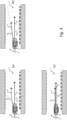
- Figs. 3a - 3c show three different exemplary embodiments of a vehicle 1 having a control device for path planning.
- the figures 3a, 3b, 3c serve to exemplify various realizations of the constraint for generating an updating path 3 which is imposed by the lateral boundaries 7b, 8b, 9a, 9b. More specifically, the figures 3a, 3b, 3c show various alternative shapes of the second portion 7b, 8b of the lateral boundaries, i.e. alternative functions defining the shape of the lateral boundaries 7, 8.
- the second portion 7b, 8b of the lateral boundaries have a parabolic shape.
- the at least one constraint based on the path generated for a previous time step is further based on a quadratic function.
- Fig. 3b illustrates an example embodiment in which the second portion 7b, 8b of the lateral boundaries have a funnel shape (as in Fig. 2 ).
- the at least one constraint based on the path 2 generated for a previous time step is further based on a linear function.
- Fig. 3c illustrates an example embodiment in which the second portion 7b, 8b of the lateral boundaries are parallel to each other along a longitudinal axis of the vehicle 1. More specifically, the second portion 7b, 8b of the lateral boundaries run in parallel with the path 2 generated for the previous time step and are spaced laterally from the path 2 generated for the previous time step with a predefined distance.
- a constraint is formed around the previous path 2 that is a path 2 generated at the previous computation time. Width of the constraint is selected such that the updated path 3 is allowed to exist only in the proximity of the previous path 2.
- the width of the constraint is expanded like a funnel (e.g. Fig. 2 and Fig. 3b ), so to allow the updated path 3 to be optimized based on e.g. a cost function and other constraints.
- this constraint can be allowed to be violated only when the optimized path 3 cannot be found without the violation.
- the rate of the funnel expansion may be a constant value with respect to distance from the ego vehicle 1 (e.g. Fig. 2 and Fig. 3b . If the rate is smaller, the updated path 3 tends to retain the shape of the previous path 2, thus enhancing the stability. In a special case, one can set the rate to be zero (e.g. Fig. 3c ), meaning the funnel does not expand, instead, the lateral boundaries are formed around the previous path 2 even for the region to the front of the vehicle 1.
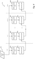
- Fig. 4 is a schematic block diagram 400 representation of a method for path planning for an autonomous or semi-autonomous vehicle according to an exemplary embodiment of the present disclosure.
- the method comprises obtaining 402a-d a drivable area of a surrounding environment of the vehicle.
- the term obtaining is herein to be interpreted broadly and encompasses receiving, retrieving, collecting, acquiring, and so forth.
- the drivable area is determined based on sensor data 401 retrieved from one or more sensor devices arranged to monitor a surrounding environment of the vehicle.
- the drivable area may comprise one or more lanes of a road segment, such as e.g. a highway stretch.
- the predefined characteristics for the path are more related to comfort aspects (lane smoothness, distance to other objects, distance to boundaries, distance to lane centre, etc.), i.e. the characteristics can be understood as optimization parameters.
- the characteristics may be dynamic (i.e.
- constraints are one the other hand more related to limitations such as physical limitations of the vehicle (e.g. turning radius), safety (e.g. traffic monitoring for collision avoidance), and in particular to the limitations imposed by the path generated for a previous time step as described in the foregoing.
- constraints may to some extent be construed as static limitations which should not be violated (e.g. the vehicle cannot turn harder than its minimum turning radius, or the vehicle cannot pass through an area more narrow than the width of the vehicle).
- the constraint based on the path generated for a previous time step is a soft constraint, i.e. it may be violated if one or more other predefined criteria are fulfilled (e.g. to avoid collision).
- the updated path for time step t may in some predefined scenarios be allowed to be formed outside of the lateral boundaries (ref. 7, 8 in Fig. 2 ).
- Fig. 5 is a schematic flow chart representation of a method 500 for path planning for an autonomous or semi-autonomous vehicle in accordance with an embodiment of the present disclosure.
- the following description will focus on the path generation step 502, however, as already exemplified in the foregoing the path can be said to be generated at least partly based on sensor data 501 that for example can be provided by a perception system of the vehicle.
- the method may further comprise controlling the vehicle to execute the generated 502 path.
- the path generation 502 is approached as an optimization problem with a cost function and a set of constraints.
- the cost function represents the characteristics that users desire for the path, and the constraints include the limitation of drivable area within which the path is allowed to exist.
- the optimal path is then found as the one that minimizes the cost function.
- the problem is formulated as a quadratic programming problem:
- the parameter vector determines the shape of the target path. For example, when the path is modeled by polynomial, the vector is polynomial coefficients.
- An advantage of this type of approach is that the optimal solution can be found in real time with efficient algorithms.
- An example of a specific implementation of a quadratic programming problem will be discussed in reference to Fig. 5 in the following.
- the method 500 comprises computing the cost function matrix and cost function vector are computed 503.
- the cost function can be understood as a mathematical representation of desired characteristics of a target path. Such characteristics may for example be a specific "smoothness" of the path, closeness to lane centre, overall length of the path, and so forth.
- the cost function values are numerically computed in a discrete space (or time) in order to compute a matrix Q and a vector c for the above mentioned Quadratic Programming problem.
- the step of computing 503 the cost function matrix and vector comprises computing 504 the "base” matrix and vector (Q, c) and then forming the augmented matrix and vector (Q a , c a ).
- the method comprises computing 506 the set of constraints, where the set of constraints further comprise at least one constraint based on a boundary of the drivable area and at least one constraint based on vehicle characteristics. More specifically, a constraints matrix and constraints vector are computed 506. Some constraints are derived from drivable area boundaries in order to ensure that optimized path exists within the drivable area (e.g. within one or more lanes on a road segment). Additionally, one may require the curvature of the path to be below a certain threshold (e.g. minimum turning radius of vehicle).
- a certain threshold e.g. minimum turning radius of vehicle.
- the step of computing 506 the constraints matrix and vector further comprises deriving 507 the at least one constraint based on a path generated for a previous time step and a predefined function.
- This constraint may also be referred to as the lateral boundaries (see e.g. ref. 7, 8 in Fig. 2 ).
- the method 500 further comprises obtaining 508 lateral boundaries based on the path from the previous time step and shaping 509 the lateral boundaries based on a predefined function (see examples in Fig. 3a, 3b, and 3c ) for a region in front of the vehicle. For example, if the lateral boundaries are to be funnel shaped for the region in front of the vehicle, the expansion of the distance between the lateral boundaries is increased proportional to the distance from the vehicle.
- an augmented constraints matrix and constraints vector (A a , b a ) is formed 510.
- the optimization problem is solved 511. This may be understood as minimizing the cost function given the predefined set of characteristics and the predefined set of constraints. In more detail, this step 511 solves the quadratic programming problem discussed in the foregoing. For this task conventional algorithms that are efficient and numerically stable may be used.
- a target path is constructed 512 from the solution 511.
- the output of the optimization 511 may be a set of coefficients of polynomial, a sequence of control inputs to the ego vehicle motion model, or some weights to form a shape of the path.
- MPC Model Predictive Control
- Model Predictive Control gives control inputs that minimizes this cost function.
- First term is a performance index that requires the resulting motion to be close the target motion (e.g. reference trajectory).
- Second term is a stabilization index that has a role to suppress the change of control inputs over time, i.e. it tries to maintain the current level of control input, which leads to stabilize the motion.
- the cost function has an inherent trade-off between the performance index and stabilization index.
- the performance index when priority is placed on the stability with a greater weighting factor, the performance is degraded, leading to the situation where the change of the updated target path from previous path is suppressed successfully, but the path fails to retain desired characteristics.
- the constraint based on the path generated at a previous time step i.e. lateral boundaries
- the conventional trade-off between performance and stability can be overcome.
- Executable instructions for performing these functions are, optionally, included in a non-transitory computer-readable storage medium or other computer program product configured for execution by one or more processors.
- Fig. 6 is a schematic side view of a vehicle having a control device 10 for path planning for an autonomous or semi-autonomous vehicle 1.
- the vehicle 1 further comprises a perception system 66 and a localization system 65 in communicative connection with the control device.
- a perception system 66 is in the present context to be understood as a system responsible for acquiring raw sensor data from on sensors 67a, 67b, 67c such as cameras, LIDARs and RADARs, ultrasonic sensors, and converting this raw data into scene understanding.
- the localization system 65 is configured to monitor a geographical position and heading of the vehicle, and may in the form of a Global Navigation Satellite System (GNSS), such as a GPS. However, the localization system may alternatively be realized as a Real Time Kinematics (RTK) GPS in order to improve accuracy.
- GNSS Global Navigation Satellite System
- RTK Real Time Kinematics
- the control device 10 comprises one or more processors 11, a memory 12, a sensor interface 13 and a communication interface 14.
- the processor(s) 11 may also be referred to as a control circuit 11 or control circuitry 11.
- the control circuit 11 is configured to execute instructions stored in the memory 12 to perform a method for path planning for an autonomous or semi-autonomous vehicle according to any one of the embodiments disclosed herein.
- the memory 12 of the control device 10 can include one or more (non-transitory) computer-readable storage mediums, for storing computer-executable instructions, which, when executed by one or more computer processors 11, for example, can cause the computer processors 11 to perform the techniques described herein.
- the memory 12 optionally includes high-speed random access memory, such as DRAM, SRAM, DDR RAM, or other random access solid-state memory devices; and optionally includes non-volatile memory, such as one or more magnetic disk storage devices, optical disk storage devices, flash memory devices, or other non-volatile solid-state storage devices.
- high-speed random access memory such as DRAM, SRAM, DDR RAM, or other random access solid-state memory devices
- non-volatile memory such as one or more magnetic disk storage devices, optical disk storage devices, flash memory devices, or other non-volatile solid-state storage devices.
- control circuitry 11 is configured to obtain (via the sensor interface 13 or communication interface 14) a drivable area of a surrounding environment of the vehicle 1.
- the drivable area may for example be defined by road boundaries or lane boundaries as detected and determined by the perception system 66 and the associated sensor devices 67a-c.
- the control device 10 may receive raw data directly from one or more sensor devices 67a-c, and the determination of a drivable area may be performed by a dedicated module of the control device 10 based on the received sensor data.
- the control circuitry 11 is further configured to generate a path within the drivable area for a time step t based on a predefined set of characteristics for the path and a predefined set of constraints.
- the set of constraints comprise at least one constraint based on a path generated for a previous time step.
- the vehicle 1 may be connected to external network(s) 62 via for instance a wireless link (e.g. for retrieving map data).
- a wireless link e.g. for retrieving map data
- the same or some other wireless link may be used to communicate with other vehicles in the vicinity of the vehicle or with local infrastructure elements.
- Cellular communication technologies may be used for long range communication such as to external networks and if the cellular communication technology used have low latency it may also be used for communication between vehicles, vehicle to vehicle (V2V), and/or vehicle to infrastructure, V2X.
- Examples of cellular radio technologies are GSM, GPRS, EDGE, LTE, 5G, 5G NR, and so on, also including future cellular solutions.
- LAN Wireless Local Area
- ETSI is working on cellular standards for vehicle communication and for instance 5G is considered as a suitable solution due to the low latency and efficient handling of high bandwidths and communication channels.
- the present disclosure introduces an additional constraint that has the following attributes.
- constraint is formed around the previous path that is a path generated at the previous computation time. Width of the constraint (lateral boundaries) is predefined and narrow such that the updated path is allowed to exist only in the proximity of the previous path.
- the width of the constraint (lateral boundaries) is expanded like a funnel (or according any other suitable function), so to allow the updated path to be optimized based on cost function and other constraints. Moreover, as an option this constraint is allowed to be violated only when the optimized path cannot be found without the violation.
- a non-transitory computer-readable storage medium storing one or more programs configured to be executed by one or more processors of a vehicle control system, the one or more programs comprising instructions for performing the method according to any one of the above-discussed embodiments.
- a cloud computing system can be configured to perform any of the methods presented herein.
- the cloud computing system may comprise distributed cloud computing resources that jointly perform the methods presented herein under control of one or more computer program products.
- a computer-accessible medium may include any tangible or non-transitory storage media or memory media such as electronic, magnetic, or optical media-e.g., disk or CD/DVD-ROM coupled to computer system via bus.
- tangible and non-transitory are intended to describe a computer-readable storage medium (or “memory”) excluding propagating electromagnetic signals, but are not intended to otherwise limit the type of physical computer-readable storage device that is encompassed by the phrase computer-readable medium or memory.
- the terms “non-transitory computer-readable medium” or “tangible memory” are intended to encompass types of storage devices that do not necessarily store information permanently, including for example, random access memory (RAM).
- Program instructions and data stored on a tangible computer-accessible storage medium in non-transitory form may further be transmitted by transmission media or signals such as electrical, electromagnetic, or digital signals, which may be conveyed via a communication medium such as a network and/or a wireless link.
- transmission media or signals such as electrical, electromagnetic, or digital signals, which may be conveyed via a communication medium such as a network and/or a wireless link.
- the communication interface 14 may be arranged to communicate with other control functions of the vehicle and may thus be seen as control interface also; however, a separate control interface (not shown) may be provided.
- Local communication within the vehicle may also be of a wireless type with protocols such as WiFi, LoRa, Zigbee, Bluetooth, or similar mid/short range technologies.
- parts of the described solution may be implemented either in the vehicle, in a system located external the vehicle, or in a combination of internal and external the vehicle; for instance in a server in communication with the vehicle, a so called cloud solution.
- sensor data may be sent to an external system and that system performs the steps to determine a drivable area of a surrounding environment of the vehicle 1.
- the different features and steps of the embodiments may be combined in other combinations than those described.
Landscapes
- Engineering & Computer Science (AREA)
- Radar, Positioning & Navigation (AREA)
- Remote Sensing (AREA)
- Automation & Control Theory (AREA)
- Physics & Mathematics (AREA)
- General Physics & Mathematics (AREA)
- Mechanical Engineering (AREA)
- Transportation (AREA)
- Aviation & Aerospace Engineering (AREA)
- Mathematical Physics (AREA)
- Business, Economics & Management (AREA)
- Medical Informatics (AREA)
- Game Theory and Decision Science (AREA)
- Health & Medical Sciences (AREA)
- Evolutionary Computation (AREA)
- Artificial Intelligence (AREA)
- Chemical & Material Sciences (AREA)
- Combustion & Propulsion (AREA)
- Computer Vision & Pattern Recognition (AREA)
- Human Computer Interaction (AREA)
- Traffic Control Systems (AREA)
Claims (7)
- Verfahren (400, 500) zur Wegplanung für ein autonomes oder halbautonomes Fahrzeug, wobei das Verfahren Folgendes umfasst:Erlangen (402a-d) einer befahrbaren Fläche einer Umgebung des Fahrzeugs;Erzeugen (403a-d, 502) eines Zielwegs innerhalb der befahrbaren Fläche zu einem Zeitschritt t basierend auf einem vordefinierten Satz von Eigenschaften für den Zielweg und einem vordefinierten Satz von Einschränkungen, wobei der vordefinierte Satz von Eigenschaften mit Komfortaspekten des Zielwegs verbunden ist und wobei der vordefinierte Satz von Eigenschaften mindestens eines von einem Ebenheitsgrad des Zielwegs, einem Abstand zur Mitte des Fahrstreifens und einer Länge des Zielwegs umfasst;wobei der Schritt des Erzeugens (403a-d, 502) des Zielwegs innerhalb der befahrbaren Fläche zu dem Zeitschritt t Folgendes umfasst:Berechnen (503) einer Kostenfunktion, wobei die Kostenfunktion eine mathematische Darstellung des vordefinierten Satzes von Eigenschaften für den Zielweg ist;Berechnen (506) des vordefinierten Satzes von Einschränkungen, wobei der vordefinierte Satz von Einschränkungen ferner mindestens eine Einschränkung, die auf einer Begrenzung der befahrbaren Fläche basiert, und mindestens eine Einschränkung, die auf Fahrzeugeigenschaften basiert, umfasst;Lösen (511) eines Optimierungsproblems basierend auf der berechneten Kostenfunktion und dem berechneten vordefinierten Satz von Einschränkungen; undBilden (512) des Zielwegs basierend auf dem gelösten Optimierungsproblem;dadurch gekennzeichnet, dass der vordefinierte Satz von Einschränkungen mindestens eine Einschränkung, die auf einem Zielweg (2) basiert, der zu einem vorhergehenden Zeitschritt erzeugt wurde, umfasst; wobei die mindestens eine Einschränkung, die auf dem Zielweg basiert, der zu dem vorhergehenden Zeitschritt erzeugt wurde, zwei seitliche Begrenzungen (7a, 7b, 8a, 8b) umfasst, die sich von dem Zielweg, der zu dem vorhergehenden Zeitschritt erzeugt wurde, in eine Fahrtrichtung des Fahrzeugs erstrecken;wobei eine Fläche zwischen den zwei seitlichen Begrenzungen (7a, 7b, 8a, 8b) eine zulässige Fläche definiert, innerhalb der zugelassen ist, dass mindestens ein Abschnitt des Zielwegs zu dem Zeitschritt t gebildet wird;wobei die zwei seitlichen Begrenzungen (7a, 7b, 8a, 8b) einen ersten Abschnitt (7a, 8a) aufweisen, der eine Längserstreckung parallel zu dem Zielweg aufweist, der zu dem vorhergehenden Zeitschritt erzeugt wurde, und wobei die zwei seitlichen Begrenzungen einen zweiten Abschnitt (8a, 8b) aufweisen, der eine Form aufweist, die auf einer vordefinierten Funktion entlang einer Kursrichtung des Fahrzeugs innerhalb der befahrbaren Fläche basiert, wobei der zweite Abschnitt (8a, 8b) der zwei seitlichen Begrenzungen (7a, 7b, 8a, 8b) eine trichterförmige Ausdehnung entlang der Kursrichtung des Fahrzeugs innerhalb der befahrbaren Fläche aufweist, wobei die trichterförmige Ausdehnung so angeordnet ist, dass sie sich mit zunehmendem Abstand vom Fahrzeug erweitert.
- Verfahren (400, 500) nach Anspruch 1, das ferner Folgendes umfasst:
wenn der Abschnitt des Zielwegs zu Zeitschritt t nicht innerhalb der zulässigen Fläche zwischen den zwei seitlichen Begrenzungen (7a, 7b, 8a, 8b) gebildet werden kann, Erhöhen eines Abstands zwischen den seitlichen Begrenzungen, bis der Abschnitt des Zielwegs innerhalb der zulässigen Fläche gebildet werden kann. - Verfahren (400, 500) nach einem der vorhergehenden Ansprüche, wobei die mindestens eine Einschränkung, die auf einem Zielweg basiert, der zu einem vorhergehenden Zeitschritt erzeugt wurde, auf einem Zielweg basiert, der zu einem unmittelbar vorhergehenden Zeitschritt t-1 erzeugt wurde.
- Verfahren (400, 500) nach einem der vorhergehenden Ansprüche, wobei der vordefinierte Satz von Einschränkungen ferner mindestens eines von einem minimalen Wenderadius des Fahrzeugs, einer Länge des Fahrzeugs, einer Breite des Fahrzeugs, einer Höhe des Fahrzeugs, einer Bodenfreiheit des Fahrzeugs und mindestens einer Fahrstreifenbegrenzung umfasst.
- Computerlesbares Speichermedium, das ein oder mehrere Programme speichert, die dazu konfiguriert sind, durch einen oder mehrere Prozessoren eines Fahrzeugsteuerungssystems ausgeführt zu werden, wobei das eine oder die mehreren Programme Anweisungen zum Durchführen des Verfahrens (400, 500) nach einem der vorhergehenden Ansprüche umfassen.
- Steuervorrichtung (10) zur Wegplanung für ein autonomes oder halbautonomes Fahrzeug (1), wobei die Steuervorrichtung (10) Steuerschaltungen (11) umfasst, die zu Folgendem konfiguriert sind:Erlangen einer befahrbaren Fläche einer Umgebung des Fahrzeugs (1) ;Erzeugen eines Zielwegs (3) innerhalb der befahrbaren Fläche zu einem Zeitschritt t basierend auf einem vordefinierten Satz von Eigenschaften für den Zielweg und einem vordefinierten Satz von Einschränkungen, wobei der vordefinierte Satz von Eigenschaften mit Komfortaspekten des Zielwegs verbunden ist und wobei der vordefinierte Satz von Eigenschaften mindestens eines von einem Ebenheitsgrad des Zielwegs, einem Abstand zur Mitte des Fahrstreifens und einer Länge des Zielwegs umfasst;wobei die Steuerschaltungen (11) ferner dazu konfiguriert sind, den Zielweg (2) innerhalb der befahrbaren Fläche zu dem Zeitschritt t durch Folgendes zu erzeugen:Berechnen einer Kostenfunktion, die den vordefinierten Satz von Eigenschaften für den Zielweg (3) umfasst;Berechnen des vordefinierten Satzes von Einschränkungen, wobei der vordefinierte Satz von Einschränkungen ferner mindestens eine Einschränkung, die auf einer Begrenzung der befahrbaren Fläche basiert, und mindestens eine Einschränkung, die auf Fahrzeugeigenschaften basiert, umfasst;Lösen eines Optimierungsproblems basierend auf der berechneten Kostenfunktion und dem berechneten vordefinierten Satz von Einschränkungen; undBilden des Zielwegs (3) basierend auf dem gelösten Optimierungsproblem;dadurch gekennzeichnet, dass der vordefinierte Satz von Einschränkungen mindestens eine Einschränkung, die auf einem Zielweg (2) basiert, der zu einem vorhergehenden Zeitschritt erzeugt wurde, umfasst; wobei die mindestens eine Einschränkung, die auf dem Zielweg basiert, der zu dem vorhergehenden Zeitschritt erzeugt wurde, zwei seitliche Begrenzungen (7a, 7b, 8a, 8b) umfasst, die sich von dem Zielweg, der zu dem vorhergehenden Zeitschritt erzeugt wurde, in eine Fahrtrichtung des Fahrzeugs erstrecken;wobei eine Fläche zwischen den zwei seitlichen Begrenzungen (7a, 7b, 8a, 8b) eine zulässige Fläche definiert, innerhalb der zugelassen ist, dass mindestens ein Abschnitt des Zielwegs zu dem Zeitschritt t gebildet wird;wobei die zwei seitlichen Begrenzungen (7a, 7b, 8a, 8b) einen ersten Abschnitt (7a, 8a) aufweisen, der eine Längserstreckung parallel zu dem Zielweg, der zu dem vorhergehenden Zeitschritt erzeugt wurde, aufweist, und wobei die zwei seitlichen Begrenzungen einen zweiten Abschnitt (8a, 8b) aufweisen, der eine Form aufweist, die auf einer vordefinierten Funktion entlang einer Kursrichtung des Fahrzeugs innerhalb der befahrbaren Fläche basiert, wobei der zweite Abschnitt (8a, 8b) der zwei seitlichen Begrenzungen (7a, 7b, 8a, 8b) eine trichterförmige Ausdehnung entlang der Kursrichtung des Fahrzeugs innerhalb der befahrbaren Fläche aufweist, wobei die trichterförmige Ausdehnung so angeordnet ist, dass sie sich mit zunehmendem Abstand vom Fahrzeug erweitert.
- Fahrzeug (1), das Folgendes umfasst:
ein Wahrnehmungssystem (66), das mindestens einen Sensor (67a-c) zur Überwachung einer Umgebung des Fahrzeugs umfasst; eine Steuervorrichtung (10) nach Anspruch 6.
Applications Claiming Priority (1)
| Application Number | Priority Date | Filing Date | Title |
|---|---|---|---|
| US16/553,874 US20210064042A1 (en) | 2019-08-28 | 2019-08-28 | Path planning for autonomous and semi-autonomous vehicles |
Publications (2)
| Publication Number | Publication Date |
|---|---|
| EP3786587A1 EP3786587A1 (de) | 2021-03-03 |
| EP3786587B1 true EP3786587B1 (de) | 2023-12-13 |
Family
ID=71737990
Family Applications (1)
| Application Number | Title | Priority Date | Filing Date |
|---|---|---|---|
| EP20186619.1A Active EP3786587B1 (de) | 2019-08-28 | 2020-07-20 | Wegplanung für autonome und halbautonome fahrzeuge |
Country Status (3)
| Country | Link |
|---|---|
| US (1) | US20210064042A1 (de) |
| EP (1) | EP3786587B1 (de) |
| CN (1) | CN112519770B (de) |
Cited By (1)
| Publication number | Priority date | Publication date | Assignee | Title |
|---|---|---|---|---|
| US12417706B1 (en) * | 2016-06-27 | 2025-09-16 | Amazon Technologies, Inc. | Annotated virtual track to inform autonomous vehicle control |
Families Citing this family (7)
| Publication number | Priority date | Publication date | Assignee | Title |
|---|---|---|---|---|
| US12291233B2 (en) * | 2019-09-27 | 2025-05-06 | Honda Motor Co., Ltd. | System and method for providing accurate trajectory following for automated vehicles in dynamic environments |
| US12187313B2 (en) * | 2020-03-13 | 2025-01-07 | Zenuity Ab | Methods and systems for vehicle path planning |
| EP4083871B1 (de) * | 2021-04-29 | 2023-11-15 | Zenseact AB | Verfahren zur automatischen entwicklung eines pfadplanungssystems für ein automatisiertes fahrsystem |
| CN113799797B (zh) * | 2021-07-27 | 2022-07-12 | 北京三快在线科技有限公司 | 轨迹规划方法、装置、存储介质及电子设备 |
| US12162514B2 (en) | 2022-01-07 | 2024-12-10 | Constructor Technology Ag | Multi-layered approach for path planning and its execution for autonomous cars |
| CN114701521B (zh) * | 2022-04-27 | 2025-07-25 | 阿波罗智能技术(北京)有限公司 | 自动驾驶方法、装置、自动驾驶车辆和电子设备 |
| CN116539057B (zh) * | 2023-04-28 | 2024-01-16 | 北京大数据先进技术研究院 | 一种最优路径确定方法、装置和电子设备 |
Citations (1)
| Publication number | Priority date | Publication date | Assignee | Title |
|---|---|---|---|---|
| US20190011910A1 (en) * | 2017-07-07 | 2019-01-10 | Zoox, Inc. | Interactions between vehicle and teleoperations system |
Family Cites Families (9)
| Publication number | Priority date | Publication date | Assignee | Title |
|---|---|---|---|---|
| US9216745B2 (en) * | 2013-09-16 | 2015-12-22 | Disney Enterprises, Inc. | Shared control of semi-autonomous vehicles including collision avoidance in multi-agent scenarios |
| US9969386B1 (en) * | 2017-01-10 | 2018-05-15 | Mitsubishi Electric Research Laboratories, Inc. | Vehicle automated parking system and method |
| US10942525B2 (en) * | 2017-05-09 | 2021-03-09 | Uatc, Llc | Navigational constraints for autonomous vehicles |
| US10725470B2 (en) * | 2017-06-13 | 2020-07-28 | GM Global Technology Operations LLC | Autonomous vehicle driving systems and methods for critical conditions |
| US10988139B2 (en) * | 2017-08-30 | 2021-04-27 | Nissan Motor Co., Ltd. | Vehicle position control method and device vehicle position control device for correcting position in drive-assisted vehicle |
| US10606277B2 (en) * | 2017-09-18 | 2020-03-31 | Baidu Usa Llc | Speed optimization based on constrained smoothing spline for autonomous driving vehicles |
| US10571921B2 (en) * | 2017-09-18 | 2020-02-25 | Baidu Usa Llc | Path optimization based on constrained smoothing spline for autonomous driving vehicles |
| DE102017220486B4 (de) * | 2017-11-16 | 2023-05-11 | Volkswagen Aktiengesellschaft | Verfahren zur Adaption einer vorbestimmten Referenzlinie für ein Kraftfahrzeug und Vorrichtung |
| US20210064031A1 (en) * | 2019-08-28 | 2021-03-04 | Zenuity Ab | Path planning for autonomous and semi-autonomous vehicles |
-
2019
- 2019-08-28 US US16/553,874 patent/US20210064042A1/en not_active Abandoned
-
2020
- 2020-07-20 EP EP20186619.1A patent/EP3786587B1/de active Active
- 2020-08-18 CN CN202010831015.8A patent/CN112519770B/zh active Active
Patent Citations (1)
| Publication number | Priority date | Publication date | Assignee | Title |
|---|---|---|---|---|
| US20190011910A1 (en) * | 2017-07-07 | 2019-01-10 | Zoox, Inc. | Interactions between vehicle and teleoperations system |
Cited By (1)
| Publication number | Priority date | Publication date | Assignee | Title |
|---|---|---|---|---|
| US12417706B1 (en) * | 2016-06-27 | 2025-09-16 | Amazon Technologies, Inc. | Annotated virtual track to inform autonomous vehicle control |
Also Published As
| Publication number | Publication date |
|---|---|
| CN112519770A (zh) | 2021-03-19 |
| US20210064042A1 (en) | 2021-03-04 |
| EP3786587A1 (de) | 2021-03-03 |
| CN112519770B (zh) | 2026-01-09 |
Similar Documents
| Publication | Publication Date | Title |
|---|---|---|
| EP3786587B1 (de) | Wegplanung für autonome und halbautonome fahrzeuge | |
| EP3786586B1 (de) | Wegplanung für autonome und halbautonome fahrzeuge | |
| CN110877610B (zh) | 碰撞回避装置 | |
| EP4118504B1 (de) | Verfahren und systeme zur fahrzeugwegplanung | |
| EP4119412B1 (de) | Verfahren zur fahrzeugbasierten datenverarbeitung, computervorrichtung und speichermedium | |
| CN110877611B (zh) | 障碍物回避装置及障碍物回避路径生成装置 | |
| GB2570887A (en) | A system for a vehicle | |
| EP3792125B1 (de) | Sichere trajektorienverfolgung in unbestimmten umgebungen | |
| US12097862B2 (en) | System and method for automated merging | |
| JP7430214B2 (ja) | 制御演算装置 | |
| EP3975137B1 (de) | System zur strassenwahrnehmung, das zum abschätzen der glaubwürdigkeit und plausibilität von fahrspuren in einem strassenmodell konfiguriert ist | |
| US20240116506A1 (en) | Control calculation apparatus and control calculation method | |
| US20250136100A1 (en) | Method and computing device for preventing collision of autonomous vehicle and recording medium having program for the same recorded thereon | |
| JP2020124994A (ja) | 車両運動制御方法及び車両運動制御装置 | |
| Shin et al. | Effects of wireless communication on integrated risk management based automated vehicle | |
| EP4624292A1 (de) | Lenkeingriffe für fahrzeuge | |
| EP4620768A1 (de) | Lenkeingriffe für fahrzeuge | |
| JP7414646B2 (ja) | 走行支援方法及び走行支援装置 | |
| JP7414647B2 (ja) | 走行支援方法及び走行支援装置 |
Legal Events
| Date | Code | Title | Description |
|---|---|---|---|
| PUAI | Public reference made under article 153(3) epc to a published international application that has entered the european phase |
Free format text: ORIGINAL CODE: 0009012 |
|
| STAA | Information on the status of an ep patent application or granted ep patent |
Free format text: STATUS: THE APPLICATION HAS BEEN PUBLISHED |
|
| AK | Designated contracting states |
Kind code of ref document: A1 Designated state(s): AL AT BE BG CH CY CZ DE DK EE ES FI FR GB GR HR HU IE IS IT LI LT LU LV MC MK MT NL NO PL PT RO RS SE SI SK SM TR |
|
| AX | Request for extension of the european patent |
Extension state: BA ME |
|
| STAA | Information on the status of an ep patent application or granted ep patent |
Free format text: STATUS: REQUEST FOR EXAMINATION WAS MADE |
|
| 17P | Request for examination filed |
Effective date: 20210830 |
|
| RBV | Designated contracting states (corrected) |
Designated state(s): AL AT BE BG CH CY CZ DE DK EE ES FI FR GB GR HR HU IE IS IT LI LT LU LV MC MK MT NL NO PL PT RO RS SE SI SK SM TR |
|
| RIN1 | Information on inventor provided before grant (corrected) |
Inventor name: MATSUDA, TAKURO |
|
| STAA | Information on the status of an ep patent application or granted ep patent |
Free format text: STATUS: EXAMINATION IS IN PROGRESS |
|
| 17Q | First examination report despatched |
Effective date: 20220228 |
|
| GRAP | Despatch of communication of intention to grant a patent |
Free format text: ORIGINAL CODE: EPIDOSNIGR1 |
|
| STAA | Information on the status of an ep patent application or granted ep patent |
Free format text: STATUS: GRANT OF PATENT IS INTENDED |
|
| INTG | Intention to grant announced |
Effective date: 20230714 |
|
| GRAS | Grant fee paid |
Free format text: ORIGINAL CODE: EPIDOSNIGR3 |
|
| GRAA | (expected) grant |
Free format text: ORIGINAL CODE: 0009210 |
|
| STAA | Information on the status of an ep patent application or granted ep patent |
Free format text: STATUS: THE PATENT HAS BEEN GRANTED |
|
| AK | Designated contracting states |
Kind code of ref document: B1 Designated state(s): AL AT BE BG CH CY CZ DE DK EE ES FI FR GB GR HR HU IE IS IT LI LT LU LV MC MK MT NL NO PL PT RO RS SE SI SK SM TR |
|
| RAP3 | Party data changed (applicant data changed or rights of an application transferred) |
Owner name: ZENUITY AB |
|
| REG | Reference to a national code |
Ref country code: GB Ref legal event code: FG4D |
|
| REG | Reference to a national code |
Ref country code: CH Ref legal event code: EP |
|
| P01 | Opt-out of the competence of the unified patent court (upc) registered |
Effective date: 20231120 |
|
| REG | Reference to a national code |
Ref country code: DE Ref legal event code: R096 Ref document number: 602020022585 Country of ref document: DE |
|
| REG | Reference to a national code |
Ref country code: IE Ref legal event code: FG4D |
|
| PG25 | Lapsed in a contracting state [announced via postgrant information from national office to epo] |
Ref country code: GR Free format text: LAPSE BECAUSE OF FAILURE TO SUBMIT A TRANSLATION OF THE DESCRIPTION OR TO PAY THE FEE WITHIN THE PRESCRIBED TIME-LIMIT Effective date: 20240314 |
|
| REG | Reference to a national code |
Ref country code: LT Ref legal event code: MG9D |
|
| PG25 | Lapsed in a contracting state [announced via postgrant information from national office to epo] |
Ref country code: LT Free format text: LAPSE BECAUSE OF FAILURE TO SUBMIT A TRANSLATION OF THE DESCRIPTION OR TO PAY THE FEE WITHIN THE PRESCRIBED TIME-LIMIT Effective date: 20231213 |
|
| REG | Reference to a national code |
Ref country code: NL Ref legal event code: MP Effective date: 20231213 |
|
| PG25 | Lapsed in a contracting state [announced via postgrant information from national office to epo] |
Ref country code: ES Free format text: LAPSE BECAUSE OF FAILURE TO SUBMIT A TRANSLATION OF THE DESCRIPTION OR TO PAY THE FEE WITHIN THE PRESCRIBED TIME-LIMIT Effective date: 20231213 |
|
| PG25 | Lapsed in a contracting state [announced via postgrant information from national office to epo] |
Ref country code: LT Free format text: LAPSE BECAUSE OF FAILURE TO SUBMIT A TRANSLATION OF THE DESCRIPTION OR TO PAY THE FEE WITHIN THE PRESCRIBED TIME-LIMIT Effective date: 20231213 Ref country code: GR Free format text: LAPSE BECAUSE OF FAILURE TO SUBMIT A TRANSLATION OF THE DESCRIPTION OR TO PAY THE FEE WITHIN THE PRESCRIBED TIME-LIMIT Effective date: 20240314 Ref country code: ES Free format text: LAPSE BECAUSE OF FAILURE TO SUBMIT A TRANSLATION OF THE DESCRIPTION OR TO PAY THE FEE WITHIN THE PRESCRIBED TIME-LIMIT Effective date: 20231213 Ref country code: BG Free format text: LAPSE BECAUSE OF FAILURE TO SUBMIT A TRANSLATION OF THE DESCRIPTION OR TO PAY THE FEE WITHIN THE PRESCRIBED TIME-LIMIT Effective date: 20240313 |
|
| REG | Reference to a national code |
Ref country code: AT Ref legal event code: MK05 Ref document number: 1640783 Country of ref document: AT Kind code of ref document: T Effective date: 20231213 |
|
| PG25 | Lapsed in a contracting state [announced via postgrant information from national office to epo] |
Ref country code: NL Free format text: LAPSE BECAUSE OF FAILURE TO SUBMIT A TRANSLATION OF THE DESCRIPTION OR TO PAY THE FEE WITHIN THE PRESCRIBED TIME-LIMIT Effective date: 20231213 |
|
| PG25 | Lapsed in a contracting state [announced via postgrant information from national office to epo] |
Ref country code: SE Free format text: LAPSE BECAUSE OF FAILURE TO SUBMIT A TRANSLATION OF THE DESCRIPTION OR TO PAY THE FEE WITHIN THE PRESCRIBED TIME-LIMIT Effective date: 20231213 Ref country code: RS Free format text: LAPSE BECAUSE OF FAILURE TO SUBMIT A TRANSLATION OF THE DESCRIPTION OR TO PAY THE FEE WITHIN THE PRESCRIBED TIME-LIMIT Effective date: 20231213 Ref country code: NO Free format text: LAPSE BECAUSE OF FAILURE TO SUBMIT A TRANSLATION OF THE DESCRIPTION OR TO PAY THE FEE WITHIN THE PRESCRIBED TIME-LIMIT Effective date: 20240313 Ref country code: NL Free format text: LAPSE BECAUSE OF FAILURE TO SUBMIT A TRANSLATION OF THE DESCRIPTION OR TO PAY THE FEE WITHIN THE PRESCRIBED TIME-LIMIT Effective date: 20231213 Ref country code: LV Free format text: LAPSE BECAUSE OF FAILURE TO SUBMIT A TRANSLATION OF THE DESCRIPTION OR TO PAY THE FEE WITHIN THE PRESCRIBED TIME-LIMIT Effective date: 20231213 Ref country code: HR Free format text: LAPSE BECAUSE OF FAILURE TO SUBMIT A TRANSLATION OF THE DESCRIPTION OR TO PAY THE FEE WITHIN THE PRESCRIBED TIME-LIMIT Effective date: 20231213 |
|
| PG25 | Lapsed in a contracting state [announced via postgrant information from national office to epo] |
Ref country code: IS Free format text: LAPSE BECAUSE OF FAILURE TO SUBMIT A TRANSLATION OF THE DESCRIPTION OR TO PAY THE FEE WITHIN THE PRESCRIBED TIME-LIMIT Effective date: 20240413 |
|
| PG25 | Lapsed in a contracting state [announced via postgrant information from national office to epo] |
Ref country code: CZ Free format text: LAPSE BECAUSE OF FAILURE TO SUBMIT A TRANSLATION OF THE DESCRIPTION OR TO PAY THE FEE WITHIN THE PRESCRIBED TIME-LIMIT Effective date: 20231213 Ref country code: AT Free format text: LAPSE BECAUSE OF FAILURE TO SUBMIT A TRANSLATION OF THE DESCRIPTION OR TO PAY THE FEE WITHIN THE PRESCRIBED TIME-LIMIT Effective date: 20231213 |
|
| PG25 | Lapsed in a contracting state [announced via postgrant information from national office to epo] |
Ref country code: SK Free format text: LAPSE BECAUSE OF FAILURE TO SUBMIT A TRANSLATION OF THE DESCRIPTION OR TO PAY THE FEE WITHIN THE PRESCRIBED TIME-LIMIT Effective date: 20231213 |
|
| PG25 | Lapsed in a contracting state [announced via postgrant information from national office to epo] |
Ref country code: SM Free format text: LAPSE BECAUSE OF FAILURE TO SUBMIT A TRANSLATION OF THE DESCRIPTION OR TO PAY THE FEE WITHIN THE PRESCRIBED TIME-LIMIT Effective date: 20231213 Ref country code: SK Free format text: LAPSE BECAUSE OF FAILURE TO SUBMIT A TRANSLATION OF THE DESCRIPTION OR TO PAY THE FEE WITHIN THE PRESCRIBED TIME-LIMIT Effective date: 20231213 Ref country code: RO Free format text: LAPSE BECAUSE OF FAILURE TO SUBMIT A TRANSLATION OF THE DESCRIPTION OR TO PAY THE FEE WITHIN THE PRESCRIBED TIME-LIMIT Effective date: 20231213 Ref country code: IT Free format text: LAPSE BECAUSE OF FAILURE TO SUBMIT A TRANSLATION OF THE DESCRIPTION OR TO PAY THE FEE WITHIN THE PRESCRIBED TIME-LIMIT Effective date: 20231213 Ref country code: IS Free format text: LAPSE BECAUSE OF FAILURE TO SUBMIT A TRANSLATION OF THE DESCRIPTION OR TO PAY THE FEE WITHIN THE PRESCRIBED TIME-LIMIT Effective date: 20240413 Ref country code: EE Free format text: LAPSE BECAUSE OF FAILURE TO SUBMIT A TRANSLATION OF THE DESCRIPTION OR TO PAY THE FEE WITHIN THE PRESCRIBED TIME-LIMIT Effective date: 20231213 Ref country code: CZ Free format text: LAPSE BECAUSE OF FAILURE TO SUBMIT A TRANSLATION OF THE DESCRIPTION OR TO PAY THE FEE WITHIN THE PRESCRIBED TIME-LIMIT Effective date: 20231213 Ref country code: AT Free format text: LAPSE BECAUSE OF FAILURE TO SUBMIT A TRANSLATION OF THE DESCRIPTION OR TO PAY THE FEE WITHIN THE PRESCRIBED TIME-LIMIT Effective date: 20231213 |
|
| PG25 | Lapsed in a contracting state [announced via postgrant information from national office to epo] |
Ref country code: PT Free format text: LAPSE BECAUSE OF FAILURE TO SUBMIT A TRANSLATION OF THE DESCRIPTION OR TO PAY THE FEE WITHIN THE PRESCRIBED TIME-LIMIT Effective date: 20240415 Ref country code: PL Free format text: LAPSE BECAUSE OF FAILURE TO SUBMIT A TRANSLATION OF THE DESCRIPTION OR TO PAY THE FEE WITHIN THE PRESCRIBED TIME-LIMIT Effective date: 20231213 |
|
| PG25 | Lapsed in a contracting state [announced via postgrant information from national office to epo] |
Ref country code: PT Free format text: LAPSE BECAUSE OF FAILURE TO SUBMIT A TRANSLATION OF THE DESCRIPTION OR TO PAY THE FEE WITHIN THE PRESCRIBED TIME-LIMIT Effective date: 20240415 Ref country code: PL Free format text: LAPSE BECAUSE OF FAILURE TO SUBMIT A TRANSLATION OF THE DESCRIPTION OR TO PAY THE FEE WITHIN THE PRESCRIBED TIME-LIMIT Effective date: 20231213 |
|
| REG | Reference to a national code |
Ref country code: DE Ref legal event code: R097 Ref document number: 602020022585 Country of ref document: DE |
|
| PG25 | Lapsed in a contracting state [announced via postgrant information from national office to epo] |
Ref country code: DK Free format text: LAPSE BECAUSE OF FAILURE TO SUBMIT A TRANSLATION OF THE DESCRIPTION OR TO PAY THE FEE WITHIN THE PRESCRIBED TIME-LIMIT Effective date: 20231213 |
|
| PLBE | No opposition filed within time limit |
Free format text: ORIGINAL CODE: 0009261 |
|
| STAA | Information on the status of an ep patent application or granted ep patent |
Free format text: STATUS: NO OPPOSITION FILED WITHIN TIME LIMIT |
|
| PG25 | Lapsed in a contracting state [announced via postgrant information from national office to epo] |
Ref country code: SI Free format text: LAPSE BECAUSE OF FAILURE TO SUBMIT A TRANSLATION OF THE DESCRIPTION OR TO PAY THE FEE WITHIN THE PRESCRIBED TIME-LIMIT Effective date: 20231213 |
|
| PG25 | Lapsed in a contracting state [announced via postgrant information from national office to epo] |
Ref country code: SI Free format text: LAPSE BECAUSE OF FAILURE TO SUBMIT A TRANSLATION OF THE DESCRIPTION OR TO PAY THE FEE WITHIN THE PRESCRIBED TIME-LIMIT Effective date: 20231213 Ref country code: DK Free format text: LAPSE BECAUSE OF FAILURE TO SUBMIT A TRANSLATION OF THE DESCRIPTION OR TO PAY THE FEE WITHIN THE PRESCRIBED TIME-LIMIT Effective date: 20231213 |
|
| 26N | No opposition filed |
Effective date: 20240916 |
|
| PG25 | Lapsed in a contracting state [announced via postgrant information from national office to epo] |
Ref country code: MC Free format text: LAPSE BECAUSE OF FAILURE TO SUBMIT A TRANSLATION OF THE DESCRIPTION OR TO PAY THE FEE WITHIN THE PRESCRIBED TIME-LIMIT Effective date: 20231213 |
|
| REG | Reference to a national code |
Ref country code: CH Ref legal event code: PL |
|
| PG25 | Lapsed in a contracting state [announced via postgrant information from national office to epo] |
Ref country code: LU Free format text: LAPSE BECAUSE OF NON-PAYMENT OF DUE FEES Effective date: 20240720 |
|
| PG25 | Lapsed in a contracting state [announced via postgrant information from national office to epo] |
Ref country code: LU Free format text: LAPSE BECAUSE OF NON-PAYMENT OF DUE FEES Effective date: 20240720 |
|
| PG25 | Lapsed in a contracting state [announced via postgrant information from national office to epo] |
Ref country code: CH Free format text: LAPSE BECAUSE OF NON-PAYMENT OF DUE FEES Effective date: 20240731 Ref country code: BE Free format text: LAPSE BECAUSE OF NON-PAYMENT OF DUE FEES Effective date: 20240731 |
|
| REG | Reference to a national code |
Ref country code: BE Ref legal event code: MM Effective date: 20240731 |
|
| PGFP | Annual fee paid to national office [announced via postgrant information from national office to epo] |
Ref country code: GB Payment date: 20250516 Year of fee payment: 6 |
|
| PGFP | Annual fee paid to national office [announced via postgrant information from national office to epo] |
Ref country code: FR Payment date: 20250516 Year of fee payment: 6 |
|
| PG25 | Lapsed in a contracting state [announced via postgrant information from national office to epo] |
Ref country code: IE Free format text: LAPSE BECAUSE OF NON-PAYMENT OF DUE FEES Effective date: 20240720 |
|
| PG25 | Lapsed in a contracting state [announced via postgrant information from national office to epo] |
Ref country code: FI Free format text: LAPSE BECAUSE OF FAILURE TO SUBMIT A TRANSLATION OF THE DESCRIPTION OR TO PAY THE FEE WITHIN THE PRESCRIBED TIME-LIMIT Effective date: 20231213 |
|
| PGFP | Annual fee paid to national office [announced via postgrant information from national office to epo] |
Ref country code: DE Payment date: 20250617 Year of fee payment: 6 |
|
| PG25 | Lapsed in a contracting state [announced via postgrant information from national office to epo] |
Ref country code: CY Free format text: LAPSE BECAUSE OF FAILURE TO SUBMIT A TRANSLATION OF THE DESCRIPTION OR TO PAY THE FEE WITHIN THE PRESCRIBED TIME-LIMIT; INVALID AB INITIO Effective date: 20200720 |
|
| PG25 | Lapsed in a contracting state [announced via postgrant information from national office to epo] |
Ref country code: HU Free format text: LAPSE BECAUSE OF FAILURE TO SUBMIT A TRANSLATION OF THE DESCRIPTION OR TO PAY THE FEE WITHIN THE PRESCRIBED TIME-LIMIT; INVALID AB INITIO Effective date: 20200720 |