EP3786504B1 - Extensible flexible hose, and method for manufacturing thereof - Google Patents
Extensible flexible hose, and method for manufacturing thereof Download PDFInfo
- Publication number
- EP3786504B1 EP3786504B1 EP19207851.7A EP19207851A EP3786504B1 EP 3786504 B1 EP3786504 B1 EP 3786504B1 EP 19207851 A EP19207851 A EP 19207851A EP 3786504 B1 EP3786504 B1 EP 3786504B1
- Authority
- EP
- European Patent Office
- Prior art keywords
- elastic
- layer
- textile reinforcement
- inner layer
- reinforcement layer
- Prior art date
- Legal status (The legal status is an assumption and is not a legal conclusion. Google has not performed a legal analysis and makes no representation as to the accuracy of the status listed.)
- Active
Links
- 238000004519 manufacturing process Methods 0.000 title claims description 57
- 238000000034 method Methods 0.000 title claims description 25
- 239000004753 textile Substances 0.000 claims description 315
- 230000002787 reinforcement Effects 0.000 claims description 256
- 239000000463 material Substances 0.000 claims description 56
- 238000000576 coating method Methods 0.000 claims description 55
- 239000011248 coating agent Substances 0.000 claims description 52
- 238000009941 weaving Methods 0.000 claims description 26
- 238000009954 braiding Methods 0.000 claims description 19
- 229920001971 elastomer Polymers 0.000 claims description 19
- 239000005060 rubber Substances 0.000 claims description 19
- 229920002725 thermoplastic elastomer Polymers 0.000 claims description 18
- 230000008878 coupling Effects 0.000 claims description 15
- 238000010168 coupling process Methods 0.000 claims description 15
- 238000005859 coupling reaction Methods 0.000 claims description 15
- 239000004677 Nylon Substances 0.000 claims description 6
- 239000004743 Polypropylene Substances 0.000 claims description 6
- 229920001778 nylon Polymers 0.000 claims description 6
- -1 polypropylene Polymers 0.000 claims description 6
- 229920001155 polypropylene Polymers 0.000 claims description 6
- 229920002972 Acrylic fiber Polymers 0.000 claims description 4
- 229920000728 polyester Polymers 0.000 claims description 4
- XLYOFNOQVPJJNP-UHFFFAOYSA-N water Substances O XLYOFNOQVPJJNP-UHFFFAOYSA-N 0.000 description 27
- 239000007788 liquid Substances 0.000 description 18
- 235000017166 Bambusa arundinacea Nutrition 0.000 description 4
- 235000017491 Bambusa tulda Nutrition 0.000 description 4
- 241001330002 Bambuseae Species 0.000 description 4
- 235000015334 Phyllostachys viridis Nutrition 0.000 description 4
- 239000011425 bamboo Substances 0.000 description 4
- 239000002985 plastic film Substances 0.000 description 3
- 229920006255 plastic film Polymers 0.000 description 3
- 230000001360 synchronised effect Effects 0.000 description 3
- 238000005299 abrasion Methods 0.000 description 2
- 238000004140 cleaning Methods 0.000 description 2
- 230000002301 combined effect Effects 0.000 description 2
- 239000013013 elastic material Substances 0.000 description 2
- 238000001125 extrusion Methods 0.000 description 2
- 239000012530 fluid Substances 0.000 description 2
- 239000004576 sand Substances 0.000 description 2
- 102000000591 Tight Junction Proteins Human genes 0.000 description 1
- 108010002321 Tight Junction Proteins Proteins 0.000 description 1
- 230000007423 decrease Effects 0.000 description 1
- 230000007547 defect Effects 0.000 description 1
- 230000000694 effects Effects 0.000 description 1
- 239000002657 fibrous material Substances 0.000 description 1
- 229920000126 latex Polymers 0.000 description 1
- 239000004816 latex Substances 0.000 description 1
- 239000002245 particle Substances 0.000 description 1
- 230000001681 protective effect Effects 0.000 description 1
- 239000002994 raw material Substances 0.000 description 1
- 238000011084 recovery Methods 0.000 description 1
- 230000000452 restraining effect Effects 0.000 description 1
- 210000001578 tight junction Anatomy 0.000 description 1
Images


Classifications
-
- F—MECHANICAL ENGINEERING; LIGHTING; HEATING; WEAPONS; BLASTING
- F16—ENGINEERING ELEMENTS AND UNITS; GENERAL MEASURES FOR PRODUCING AND MAINTAINING EFFECTIVE FUNCTIONING OF MACHINES OR INSTALLATIONS; THERMAL INSULATION IN GENERAL
- F16L—PIPES; JOINTS OR FITTINGS FOR PIPES; SUPPORTS FOR PIPES, CABLES OR PROTECTIVE TUBING; MEANS FOR THERMAL INSULATION IN GENERAL
- F16L11/00—Hoses, i.e. flexible pipes
- F16L11/04—Hoses, i.e. flexible pipes made of rubber or flexible plastics
- F16L11/08—Hoses, i.e. flexible pipes made of rubber or flexible plastics with reinforcements embedded in the wall
- F16L11/085—Hoses, i.e. flexible pipes made of rubber or flexible plastics with reinforcements embedded in the wall comprising one or more braided layers
-
- F—MECHANICAL ENGINEERING; LIGHTING; HEATING; WEAPONS; BLASTING
- F16—ENGINEERING ELEMENTS AND UNITS; GENERAL MEASURES FOR PRODUCING AND MAINTAINING EFFECTIVE FUNCTIONING OF MACHINES OR INSTALLATIONS; THERMAL INSULATION IN GENERAL
- F16L—PIPES; JOINTS OR FITTINGS FOR PIPES; SUPPORTS FOR PIPES, CABLES OR PROTECTIVE TUBING; MEANS FOR THERMAL INSULATION IN GENERAL
- F16L11/00—Hoses, i.e. flexible pipes
- F16L11/02—Hoses, i.e. flexible pipes made of fibres or threads, e.g. of textile which may or may not be impregnated, or provided with an impermeable layer, e.g. fire-hoses
-
- B—PERFORMING OPERATIONS; TRANSPORTING
- B29—WORKING OF PLASTICS; WORKING OF SUBSTANCES IN A PLASTIC STATE IN GENERAL
- B29C—SHAPING OR JOINING OF PLASTICS; SHAPING OF MATERIAL IN A PLASTIC STATE, NOT OTHERWISE PROVIDED FOR; AFTER-TREATMENT OF THE SHAPED PRODUCTS, e.g. REPAIRING
- B29C48/00—Extrusion moulding, i.e. expressing the moulding material through a die or nozzle which imparts the desired form; Apparatus therefor
- B29C48/022—Extrusion moulding, i.e. expressing the moulding material through a die or nozzle which imparts the desired form; Apparatus therefor characterised by the choice of material
-
- B—PERFORMING OPERATIONS; TRANSPORTING
- B29—WORKING OF PLASTICS; WORKING OF SUBSTANCES IN A PLASTIC STATE IN GENERAL
- B29C—SHAPING OR JOINING OF PLASTICS; SHAPING OF MATERIAL IN A PLASTIC STATE, NOT OTHERWISE PROVIDED FOR; AFTER-TREATMENT OF THE SHAPED PRODUCTS, e.g. REPAIRING
- B29C48/00—Extrusion moulding, i.e. expressing the moulding material through a die or nozzle which imparts the desired form; Apparatus therefor
- B29C48/03—Extrusion moulding, i.e. expressing the moulding material through a die or nozzle which imparts the desired form; Apparatus therefor characterised by the shape of the extruded material at extrusion
- B29C48/09—Articles with cross-sections having partially or fully enclosed cavities, e.g. pipes or channels
-
- B—PERFORMING OPERATIONS; TRANSPORTING
- B29—WORKING OF PLASTICS; WORKING OF SUBSTANCES IN A PLASTIC STATE IN GENERAL
- B29C—SHAPING OR JOINING OF PLASTICS; SHAPING OF MATERIAL IN A PLASTIC STATE, NOT OTHERWISE PROVIDED FOR; AFTER-TREATMENT OF THE SHAPED PRODUCTS, e.g. REPAIRING
- B29C48/00—Extrusion moulding, i.e. expressing the moulding material through a die or nozzle which imparts the desired form; Apparatus therefor
- B29C48/15—Extrusion moulding, i.e. expressing the moulding material through a die or nozzle which imparts the desired form; Apparatus therefor incorporating preformed parts or layers, e.g. extrusion moulding around inserts
- B29C48/151—Coating hollow articles
-
- F—MECHANICAL ENGINEERING; LIGHTING; HEATING; WEAPONS; BLASTING
- F16—ENGINEERING ELEMENTS AND UNITS; GENERAL MEASURES FOR PRODUCING AND MAINTAINING EFFECTIVE FUNCTIONING OF MACHINES OR INSTALLATIONS; THERMAL INSULATION IN GENERAL
- F16L—PIPES; JOINTS OR FITTINGS FOR PIPES; SUPPORTS FOR PIPES, CABLES OR PROTECTIVE TUBING; MEANS FOR THERMAL INSULATION IN GENERAL
- F16L11/00—Hoses, i.e. flexible pipes
- F16L11/04—Hoses, i.e. flexible pipes made of rubber or flexible plastics
- F16L11/12—Hoses, i.e. flexible pipes made of rubber or flexible plastics with arrangements for particular purposes, e.g. specially profiled, with protecting layer, heated, electrically conducting
-
- B—PERFORMING OPERATIONS; TRANSPORTING
- B29—WORKING OF PLASTICS; WORKING OF SUBSTANCES IN A PLASTIC STATE IN GENERAL
- B29K—INDEXING SCHEME ASSOCIATED WITH SUBCLASSES B29B, B29C OR B29D, RELATING TO MOULDING MATERIALS OR TO MATERIALS FOR MOULDS, REINFORCEMENTS, FILLERS OR PREFORMED PARTS, e.g. INSERTS
- B29K2105/00—Condition, form or state of moulded material or of the material to be shaped
- B29K2105/06—Condition, form or state of moulded material or of the material to be shaped containing reinforcements, fillers or inserts
- B29K2105/08—Condition, form or state of moulded material or of the material to be shaped containing reinforcements, fillers or inserts of continuous length, e.g. cords, rovings, mats, fabrics, strands or yarns
- B29K2105/0809—Fabrics
- B29K2105/0827—Braided fabrics
-
- B—PERFORMING OPERATIONS; TRANSPORTING
- B29—WORKING OF PLASTICS; WORKING OF SUBSTANCES IN A PLASTIC STATE IN GENERAL
- B29K—INDEXING SCHEME ASSOCIATED WITH SUBCLASSES B29B, B29C OR B29D, RELATING TO MOULDING MATERIALS OR TO MATERIALS FOR MOULDS, REINFORCEMENTS, FILLERS OR PREFORMED PARTS, e.g. INSERTS
- B29K2995/00—Properties of moulding materials, reinforcements, fillers, preformed parts or moulds
- B29K2995/0037—Other properties
- B29K2995/0046—Elastic
-
- B—PERFORMING OPERATIONS; TRANSPORTING
- B29—WORKING OF PLASTICS; WORKING OF SUBSTANCES IN A PLASTIC STATE IN GENERAL
- B29L—INDEXING SCHEME ASSOCIATED WITH SUBCLASS B29C, RELATING TO PARTICULAR ARTICLES
- B29L2023/00—Tubular articles
- B29L2023/005—Hoses, i.e. flexible
Definitions
- the present invention relates to the technical field of telescopic water pipes, and in particular to an extensible flexible hose, and method for manufacturing thereof.
- WO 2016/098063 A1 describes a hose comprising at least one inner layer and one outer layer made of elastic polymeric material, and at least one textile reinforcement layer interposed between said at least one inner and outer layers.
- the inner layer and the outer layer are reciprocally coupled to form a unitary tubular member internally to which the textile reinforcement layer is embedded.
- the unitary tubular member has an elasticity such to automatically elongate upon the working pressure given by the liquid flowing therethrough to increase its original length and such to automatically recover once the working pressure stops.
- the textile reinforcement layer is susceptible to move from a rest configuration that has when the working pressure stops to a working configuration that has when said unitary tubular member elongates upon the working pressure and vice-versa.
- WO 2017/187233 A1 describes a flexible hose for transporting fluid.
- the hose comprises at least one inner layer made of a first elastic polymeric material, at least one outer layer made of a second elastic polymeric material, at least one textile reinforcement layer interposed between said at least one inner layer and at least one outer layer.
- the at least one inner layer and the at least one outer layer are reciprocally coupled to form a unitary tubular member internally to which the at least one textile reinforcement layer is embedded.
- the unitary tubular member has an elasticity such to automatically enlarge upon the working pressure given by the liquid flowing therethrough to increase its original diameter and such to automatically recovery once the working pressure stops for assuming again the original diameter.
- the at least one textile reinforcement layer is susceptible to move from a rest configuration that has when the working pressure stops to a working configuration that has when said unitary tubular member enlarges upon the working pressure and vice-versa.
- US 2016/0245430 A1 describes a flexible hose for transporting a fluid, including an outer sheath and an inner tube.
- the inner tube has an inner layer made of a first elastic polymeric material and an outer layer made of a second elastic polymeric material with a textile reinforcement layer embedded within the inner tube to form a unitary tubular member.
- the elasticity of the unitary tubular member is such that it automatically elongates under the working pressure provided by a liquid flowing therethrough and automatically recovers its original length when the working pressure stops.
- the textile reinforcement layer is adapted to move from a rest configuration when there is no working pressure, to a working configuration when the unitary tubular member elongates under the working pressure.
- the existing telescopic water pipe on the market mostly consist of inner core elastic tube and outer sheath, is an elastic tube, made of latex, rubber or a TPR thermoplastic elastomer as a raw material. Due to the high elasticity of the telescopic water pipe, when the telescopic water pipe is connected with 3-10 kg of pressurized water, under the protection by the outer sheath, the radial water-passing area and longitudinal length of the telescopic water pipe can be expanded to extend by 2-4 times; and when the pressurized water source is turned off, under the resilience force of the inner core elastic tube, the telescopic water pipe quickly discharges the residual water in the pipe and retracts to the original product size.
- the telescopic water pipe is easy to use and is very popular among customers at home and abroad.
- the service life of the telescopic water pipe on the market is too low to meet people's expectations, also not convenient to store and easily stain the outer sheath.
- US patent US20180299038A1 discloses a telescopic water pipe with two-layer woven structure, including an inner layer and an outer layer made of an elastic polymeric material, and a first and second textile reinforcement layers which could stretch axially and radially interposed between the inner and the outer layers.
- the radial expansion the extensible flexible hose can be controlled and the longitudinal length of the telescopic water pipe can have a maximum 2.5 times elongation with respect to its original length, which could prolong the longitudinal length of the telescopic water pipe effectively.
- the textile reinforcement layers mainly contribute to the restriction of the expansion and determines the elongation of the hose as well, which decreases the elasticity of the flexible hose, and the manufacturing process of the hose is intricate. Also, the two textile reinforcement layers likely could break the connection within the hose, causing local overexpansion, that could break the unity of the flexible hose and lower its service life.
- An objective of the present invention is to provide an extensible flexible hose and method for manufacturing thereof, so as to solve the above problems existed in the prior art, to improve the phenomenon that the telescopic water pipe is liable to be damaged due to strong friction between inner core and outer sheath, to prolong the service life of the extensible flexible hose.
- the whole hose body is made of elastic materials, which changed the structure of traditional hose, having advantages as great elasticity, easy to carry, simple to clean, and convenient to store.
- An extensible flexible hose comprises one elastic inner layer, one elastic textile reinforcement layer and one elastic outer layer, where the elastic textile reinforcement layer placed on the outer surface of the elastic inner layer, the elastic outer layer disposed on the elastic textile reinforcement layer, while the elastic inner layer and the elastic textile reinforcement layer are reciprocally coupled, the elastic outer layer and the uncovered surface area of the elastic inner layer are reciprocally joined to form a unitary tubular member.
- the one elastic outer layer and the one elastic inner layer may be reciprocally joined except at the regions occupied by the elastic textile reinforcement layer.
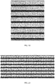
- the elastic textile reinforcement layer comprising a twill weave textile layer, with stretch yarns longitudinally distributed among, wherein said twill weave textile layer is prepared by twilled weaving, while said stretch yarns being parallelly woven in between.
- the integrated combination of elastic inner layer, elastic textile reinforcement layer and elastic outer layer, providing a tubular member features with minimum bulkiness and compact structure, which changes the traditional flexible hose with the structure of the inner core and the outer sheath being separated.
- elastic inner layer With the elasticity of the whole hoes body, it guarantees the hose could increasing its length of at maximum 5 times with respect to its original length under working pressure and retracting fast once the working pressure stops, which increases the working efficiency significantly.
- the elastic textile reinforcement layer has an axial elasticity and a radial constraint force, that allows the elastic textile reinforcement layer automatically elongating and restricts the elastic textile reinforcement layer from automatically enlarging under working pressure given by a liquid flowing therethrough.
- the elastic textile reinforcement layer increases its length of at maximum 7 times with respect to its original length under working pressure, and the elastic textile reinforcement layer also can withstand a working pressure of 8 to 30 bar, which has a relatively high burst pressure.
- the number of the stretch yarns among the elastic textile reinforcement layer ranges from 8 to 96, the diameter of the stretch yarn ranges from 0.25mm to 2mm.
- the twill weave textile layer being made of in a material selected among the group consisting of polyester, polypropylene, nylon and acrylic fibres, while the yarn counts of the material using in the twill weave textile layer ranges from 10D to 5000D.
- the twill weave textile layer is made of elastic materials and fiber materials, being prepared by twilled weaving, could restraining the radial enlargement but to yield in axial direction with the combined effect of the stretch yarns, further restricting the motion of both elastic inner layer and elastic outer layer to increase the utilization rate and to prolong the service life the extensible flexible hose.
- the elastic inner layer is made of thermoplastic elastomer material or rubber material, and the inner diameter of the elastic inner layer ranges from 3mm to 95mm, and the external diameter of the elastic inner layer ranges from 3.2mm to 100mm, and the thickness of the elastic inner layer ranges from 0.2mm to 10mm.
- the elastic outer layer is made of thermoplastic elastomer material or rubber material, and the thickness of the elastic outer layer ranges from 0.2mm to 10mm.
- the elastic outer layer is processed by extrusion or coating process that could guarantee the tight junction between the elastic outer layer and the other two layers.
- the elastic outer layer can effectively prevent small hard objects (e.g., grains of sand) entering the elastic textile reinforcement layer which could cause burst of elastic inner layer during the friction between the elastic textile reinforcement layer and the elastic inner layer to reduce its service life.
- the elastic inner layer and elastic textile reinforcement layer can be further joined due to existence of the elastic outer layer, which can guarantee the synchronous telescoping of the unitary tubular member and reduce the friction between the elastic textile reinforcement layer and elastic inner layer, can prolong the service life of stretch yarns.
- the elastic outer layer also gives the hose a minimum bulkiness and compact structure that can contribute to a higher elongation and better elasticity, can further increase the working efficiency of the hose.
- the elastic outer layer is simple to clean and practical to be stored.
- twill weave textile layer is meant a layer consisting of at least two yarns or groups of yarns laying on a supporting layer with opposite inclinations and connected to one another alternately to form a weave. In a weaving process, one yarn is interlaced with another yarn once above and then below the latter.
- the elastic textile reinforcement layer of the extensible hose of the present invention may be susceptible to move between a rest configuration that has at rest, i.e. when the liquid does not flow through the unitary tubular member, and a working configuration that has when the unitary tubular member is actuated by the working pressure of the liquid flowing therethrough.
- the elastic textile reinforcement layer only extends axially to accompany the elongation of the unitary tubular member.
- the maximum axial elongation of the elastic textile reinforcement layer is the same as the maximum axial elongation of the unitary tubular member.
- two ends of the unitary tubular member are respectively provided with a joint, the joint comprises a convex connector, a pawl type snap joint, and a locking piece.
- the convex connector inserted into the end of the unitary tubular member, the pawl type snap joint connected to the exterior of the unitary tubular member, the locking piece fastened on the exterior of the pawl type snap joint.
- the convex connector being a hollow structural connector, comprises a body part, a convex part, a spacing part, a screw thread part.
- the body part connected with the convex part, the end of the convex part connected with the spacing part, the screw thread part set on the exterior of the body part, the screw thread part also connected with the locking piece.
- the joint designed to be removably connected with the unitary tubular member, while the spacing part can prevent the elastic inner layer from moving away. With the combined effect of locking piece and convex connector, the elastic inner layer could be connected tightly on the exterior of the convex part, making sure the tubular member stay within the joint under working pressure.
- the joint provided with one of the following connector structures at an end away from the unitary tubular member: a quick-connect connection structure, an internally threaded joint structure or an externally threaded joint structure.
- the hose can be manufactured by a method which may include in sequence the following steps: a)providing an elastic inner layer formed by extruding or coating; b) elongating between 2 to 7 times of the elastic inner layer with respect to its original length, and placing an elastic textile reinforcement layer on the elongated elastic inner layer to obtain a semifinished hose; c) extruding or coating an elastic outer layer on the semifinished hose.
- the step b) of placing an elastic textile reinforcement layer includes a step of the elastic textile reinforcement layer reciprocally coupling to the outer surface of elongated elastic inner layer to obtain a semifinished hose.
- the step c) of extruding or coating an elastic outer layer includes a step of the one elastic outer layer and the uncovered surface area of the one elastic inner layer being reciprocally joined to form a unitary tubular member.
- the manufacturing method includes a production line, the production line set up by the combination of a selected group consisting of extruding station, braiding station, coating station.
- the hose comprises one elastic inner layer, one elastic textile reinforcement layer and one elastic outer layer, where the elastic textile reinforcement layer placed on the outer surface of the elastic inner layer, the elastic outer layer disposed on the elastic textile reinforcement layer, while the elastic inner layer and the elastic textile reinforcement layer are reciprocally coupled, the elastic outer layer and the uncovered surface area of the elastic inner layer are reciprocally joined to form a unitary tubular member.
- the elastic textile reinforcement layer is formed by a twill weave textile layer.
- the hose can be manufactured by a method which may include in sequence the following steps: a)providing an elastic inner layer formed by extruding or coating; b) elongating between 2 to 7 times of the stretch yarns with respect to its original length, then twilled weaving with the elongated stretch yarns to form an elastic textile reinforcement layer, and placing the elastic textile reinforcement layer on the elastic inner layer at the same time to obtain a semifinished hose; c) extruding or coating an elastic outer layer on the semifinished hose.
- the step b) of placing an elastic textile reinforcement layer includes a step of the one elastic inner layer reciprocally coupling to the inner surface of elongated elastic textile reinforcement layer to obtain a semifinished hose.
- the step c) of extruding or coating an elastic outer layer includes a step of the one elastic outer layer and the uncovered surface area of the one elastic inner layer being reciprocally joined to form a unitary tubular member.
- the manufacturing method includes a production line, the production line set up by the combination of a selected group consisting of extruding station, braiding station, coating station.
- the above extendable hose can be manufactured in a simple and fast manner.
- the extensible hose can be manufactured automatically in line, without the aid of human operators.
- the present invention provides an extensible flexible hose with an integrated tubular member form, which changes the traditional flexible hose with structure of the inner core and the outer sheath being separated, had overcome the disadvantage of short service life due to strong friction between the inner core and outer sheath of the traditional hose.
- the elastic outer layer is made of thermoplastic elastomer material or rubber material, which makes it simple to clean.
- the present invention also provides a production line set up by the combination of a selected group consisting of extruding station, braiding station, coating station, which can adjust to various manufacturing conditions, has advantages as low operation cost, simple process, etc.
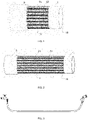
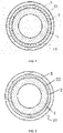
- An extensible flexible hose comprises one elastic inner layer 1, one elastic textile reinforcement layer 2 and one elastic outer layer 3, where the elastic textile reinforcement layer placed on the outer surface of the elastic inner layer, the elastic outer layer disposed on the elastic textile reinforcement layer, while the elastic inner layer and the elastic textile reinforcement layer are reciprocally coupled, the elastic outer layer and the uncovered surface area of the elastic inner layer are reciprocally joined to form a unitary tubular member 10.
- the one elastic outer layer and the one elastic inner layer may be reciprocally joined except at the regions occupied by the elastic textile reinforcement layer.
- the elastic textile reinforcement layer comprising a twill weave textile layer 21, with stretch yarns 22 longitudinally distributed among, as shown in FIG. 1-2 and FIG. 19-20 .
- the twill weave textile layer is prepared by twilled weaving, while said stretch yarns being parallelly woven in between.
- the elastic textile reinforcement layer has an axial elasticity and a radial constraint force, that allows the elastic textile reinforcement layer automatically elongating and restricts the elastic textile reinforcement layer from automatically enlarging under working pressure given by a liquid flowing therethrough.
- the elastic textile reinforcement layer increases its length of 4.6 times with respect to its original length under working pressure of 6 bar.
- the elastic textile reinforcement layer increases its length of at maximum 7 times with respect to its original length under working pressure, and the elastic textile reinforcement layer also can withstand a working pressure of 8 bar, which has a relatively high burst pressure.
- the number of the stretch yarns among the elastic textile reinforcement layer is 8, the diameter of the stretch yarn is 1.2mm.
- the twill weave textile layer is made of polypropylene, while the yarn counts of the material using in the twill weave textile layer is 800D.
- the stretchable outer diameter of the elastic textile reinforcement layer is 10mm.
- the elastic inner layer is made of thermoplastic elastomer material, and the inner diameter of the elastic inner layer is 6mm, and the external diameter of the elastic inner layer is 9mm, and the thickness of the elastic inner layer is 1.5mm.
- the elastic outer layer is made of thermoplastic elastomer material, and the thickness of the elastic outer layer is 1mm.
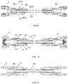
- two ends of the unitary tubular member are respectively provided with a joint 4, the joint comprises a convex connector 41, a pawl type snap joint 42, and a locking piece 43.
- the convex connector inserted into the end of the unitary tubular member, the pawl type snap joint connected to the exterior of the unitary tubular member, the locking piece fastened on the exterior of the pawl type snap joint.
- the joint also has a through-hole 44 within, which can connect to the inner space of elastic inner layer.
- the convex connector being a hollow structural connector, comprises a body part 411, a convex part 412, a spacing part 413, a screw thread part 414.
- the body part connected with the convex part, the end of the convex part connected with the spacing part, the screw thread part set on the exterior of the body part, the screw thread part also connected with the locking piece.
- the joint designed to be removably connected with the unitary tubular member, while the spacing part can prevent the elastic inner layer from moving away.
- the joint provided with one of the following connector structures at an end away from the unitary tubular member: a quick-connect connection structure 5, an internally threaded joint structure 6 or an externally threaded joint structure 7.
- An extensible flexible hose comprises one elastic inner layer 1, one elastic textile reinforcement layer 2 and one elastic outer layer 3, where the elastic textile reinforcement layer placed on the outer surface of the elastic inner layer, the elastic outer layer disposed on the elastic textile reinforcement layer, while the elastic inner layer and the elastic textile reinforcement layer are reciprocally coupled, the elastic outer layer and the uncovered surface area of the elastic inner layer are reciprocally joined to form a unitary tubular member 10.
- the one elastic outer layer and the one elastic inner layer may be reciprocally joined except at the regions occupied by the elastic textile reinforcement layer.
- the elastic textile reinforcement layer comprising a twill weave textile layer 21, with stretch yarns 22 longitudinally distributed among, as shown in FIG. 1-2 and FIG. 19-20 .
- the twill weave textile layer is prepared by twilled weaving, while said stretch yarns being parallelly woven in between.
- the elastic textile reinforcement layer has an axial elasticity and a radial constraint force, that allows the elastic textile reinforcement layer automatically elongating and restricts the elastic textile reinforcement layer from automatically enlarging under working pressure given by a liquid flowing therethrough.
- the elastic textile reinforcement layer increases its length of 3 times with respect to its original length under working pressure of 8 bar.
- the elastic textile reinforcement layer increases its length of at maximum 4.5 times with respect to its original length under working pressure, and the elastic textile reinforcement layer also can withstand a working pressure of 10 bar, which has a relatively high burst pressure.
- the number of the stretch yarns among the elastic textile reinforcement layer is 16, the diameter of the stretch yarn is 0.7mm.
- the stretchable outer diameter of the elastic textile reinforcement layer is 13mm.
- the twill weave textile layer being made of polyester, while the yarn counts of the material using in the twill weave textile layer is 600D.
- the elastic inner layer is made of thermoplastic elastomer material, and the inner diameter of the elastic inner layer is 9mm, and the external diameter of the elastic inner layer is 12mm, and the thickness of the elastic inner layer is 1.5mm.
- the elastic outer layer is made of thermoplastic elastomer material, and the thickness of the elastic outer layer is 2mm.
- two ends of the unitary tubular member are respectively provided with a joint 4, the joint comprises a convex connector 41, a pawl type snap joint 42, and a locking piece 43.
- the convex connector inserted into the end of the unitary tubular member, the pawl type snap joint connected to the exterior of the unitary tubular member, the locking piece fastened on the exterior of the pawl type snap joint.
- the joint also has a through-hole 44 within, which can connect to the inner space of elastic inner layer.
- the convex connector being a hollow structural connector, comprises a body part 411, a convex part 412, a spacing part 413, a screw thread part 414.
- the body part connected with the convex part, the end of the convex part connected with the spacing part, the screw thread part set on the exterior of the body part, the screw thread part also connected with the locking piece.
- the joint designed to be removably connected with the unitary tubular member, while the spacing part can prevent the elastic inner layer from moving away.
- the joint provided with one of the following connector structures at an end away from the unitary tubular member: a quick-connect connection structure 5, an internally threaded joint structure 6 or an externally threaded joint structure 7.
- An extensible flexible hose comprises one elastic inner layer 1, one elastic textile reinforcement layer 2 and one elastic outer layer 3, where the elastic textile reinforcement layer placed on the outer surface of the elastic inner layer, the elastic outer layer disposed on the elastic textile reinforcement layer, while the elastic inner layer and the elastic textile reinforcement layer are reciprocally coupled, the elastic outer layer and the uncovered surface area of the elastic inner layer are reciprocally joined to form a unitary tubular member 10.
- the one elastic outer layer and the one elastic inner layer may be reciprocally joined except at the regions occupied by the elastic textile reinforcement layer.
- the elastic textile reinforcement layer comprising a twill weave textile layer 21, with stretch yarns 22 longitudinally distributed among, as shown in FIG. 1-2 and FIG. 19-20 .
- the twill weave textile layer is prepared by twilled weaving, while said stretch yarns being parallelly woven in between.
- the elastic textile reinforcement layer has an axial elasticity and a radial constraint force, that allows the elastic textile reinforcement layer automatically elongating and restricts the elastic textile reinforcement layer from automatically enlarging under working pressure given by a liquid flowing therethrough.
- the elastic textile reinforcement layer increases its length of 1.8 times with respect to its original length under working pressure of 15 bar.
- the elastic textile reinforcement layer increases its length of at maximum 3 times with respect to its original length under working pressure, and the elastic textile reinforcement layer also can withstand a working pressure of 30 bar, which has a relatively high burst pressure.
- the number of the stretch yarns among the elastic textile reinforcement layer is 48, the diameter of the stretch yarn is 2mm.
- the stretchable outer diameter of the elastic textile reinforcement layer is 34mm.
- the twill weave textile layer being made of nylon, while the yarn counts of the material using in the twill weave textile layer is 3000D.
- the elastic inner layer is made of rubber material, and the inner diameter of the elastic inner layer is 20mm, and the external diameter of the elastic inner layer is 30mm, and the thickness of the elastic inner layer is 5mm.
- the elastic outer layer is made of rubber material, and the thickness of the elastic outer layer is 4mm.
- two ends of the unitary tubular member are respectively provided with a joint 4, the joint comprises a convex connector 41, a pawl type snap joint 42, and a locking piece 43.
- the convex connector inserted into the end of the unitary tubular member, the pawl type snap joint connected to the exterior of the unitary tubular member, the locking piece fastened on the exterior of the pawl type snap joint.
- the joint also has a through-hole 44 within, which can connect to the inner space of elastic inner layer.
- the convex connector being a hollow structural connector, comprises a body part 411, a convex part 412, a spacing part 413, a screw thread part 414.
- the body part connected with the convex part, the end of the convex part connected with the spacing part, the screw thread part set on the exterior of the body part, the screw thread part also connected with the locking piece.
- the joint designed to be removably connected with the unitary tubular member, while the spacing part can prevent the elastic inner layer from moving away.
- the joint provided with one of the following connector structures at an end away from the unitary tubular member: a quick-connect connection structure 5, an internally threaded joint structure 6 or an externally threaded joint structure 7.
- An extensible flexible hose comprises one elastic inner layer 1, one elastic textile reinforcement layer 2 and one elastic outer layer 3, where the elastic textile reinforcement layer placed on the outer surface of the elastic inner layer, the elastic outer layer disposed on the elastic textile reinforcement layer, while the elastic inner layer and the elastic textile reinforcement layer are reciprocally coupled, the elastic outer layer and the uncovered surface area of the elastic inner layer are reciprocally joined to form a unitary tubular member 10.
- the one elastic outer layer and the one elastic inner layer may be reciprocally joined except at the regions occupied by the elastic textile reinforcement layer.
- the elastic textile reinforcement layer comprising a twill weave textile layer 21, with stretch yarns 22 longitudinally distributed among, as shown in FIG. 1-2 and FIG. 19-20 .
- the twill weave textile layer is prepared by twilled weaving, while said stretch yarns being parallelly woven in between.
- the elastic textile reinforcement layer has an axial elasticity and a radial constraint force, that allows the elastic textile reinforcement layer automatically elongating and restricts the elastic textile reinforcement layer from automatically enlarging under working pressure given by a liquid flowing therethrough.
- the elastic textile reinforcement layer increases its length of 2.5 times with respect to its original length under working pressure of 10 bar.
- the elastic textile reinforcement layer increases its length of at maximum 4 times with respect to its original length under working pressure, and the elastic textile reinforcement layer also can withstand a working pressure of 20 bar, which has a relatively high burst pressure.
- the number of the stretch yarns among the elastic textile reinforcement layer is 24, the diameter of the stretch yarn is 1mm.
- the stretchable outer diameter of the elastic textile reinforcement layer is 18mm.
- the twill weave textile layer being made of acrylic fibres, while the yarn counts of the material using in the twill weave textile layer is 1000D.
- the elastic inner layer is made of rubber material, and the inner diameter of the elastic inner layer is 12mm, and the external diameter of the elastic inner layer is 16mm, and the thickness of the elastic inner layer is 2mm.
- the elastic outer layer is made of rubber material, and the thickness of the elastic outer layer is 2mm.
- two ends of the unitary tubular member are respectively provided with a joint 4, the joint comprises a convex connector 41, a pawl type snap joint 42, and a locking piece 43.
- the convex connector inserted into the end of the unitary tubular member, the pawl type snap joint connected to the exterior of the unitary tubular member, the locking piece fastened on the exterior of the pawl type snap joint.
- the joint also has a through-hole 44 within, which can connect to the inner space of elastic inner layer.
- the convex connector being a hollow structural connector, comprises a body part 411, a convex part 412, a spacing part 413, a screw thread part 414.
- the body part connected with the convex part, the end of the convex part connected with the spacing part, the screw thread part set on the exterior of the body part, the screw thread part also connected with the locking piece.
- the joint designed to be removably connected with the unitary tubular member, while the spacing part can prevent the elastic inner layer from moving away.
- the joint provided with one of the following connector structures at an end away from the unitary tubular member: a quick-connect connection structure 5, an internally threaded joint structure 6 or an externally threaded joint structure 7.
- An extensible flexible hose comprises one elastic inner layer 1, one elastic textile reinforcement layer 2 and one elastic outer layer 3, where the elastic textile reinforcement layer placed on the outer surface of the elastic inner layer, the elastic outer layer disposed on the elastic textile reinforcement layer, while the elastic inner layer and the elastic textile reinforcement layer are reciprocally coupled, the elastic outer layer and the uncovered surface area of the elastic inner layer are reciprocally joined to form a unitary tubular member 10.
- the one elastic outer layer and the one elastic inner layer may be reciprocally joined except at the regions occupied by the elastic textile reinforcement layer.
- the elastic textile reinforcement layer comprising a twill weave textile layer 21, with stretch yarns 22 longitudinally distributed among, as shown in FIG. 1-2 and FIG. 19-20 .
- the twill weave textile layer is prepared by twilled weaving, while the stretch yarns being parallelly woven in between.
- the elastic textile reinforcement layer has an axial elasticity and a radial constraint force, that allows the elastic textile reinforcement layer automatically elongating and restricts the elastic textile reinforcement layer from automatically enlarging under working pressure given by a liquid flowing therethrough.
- the elastic textile reinforcement layer increases its length of 1.5 times with respect to its original length under working pressure of 7 bar.
- the elastic textile reinforcement layer increases its length of at maximum 2.5 times with respect to its original length under working pressure, and the elastic textile reinforcement layer also can withstand a working pressure of 15 bar, which has a relatively high burst pressure.
- the number of the stretch yarns among the elastic textile reinforcement layer is 96, the diameter of the stretch yarn is 1.5mm.
- the twill weave textile layer being made of polypropylene, while the yarn counts of the material using in the twill weave textile layer is 5000D.
- the elastic inner layer is made of thermoplastic elastomer material, and the inner diameter of the elastic inner layer is 72mm, and the external diameter of the elastic inner layer is 86mm, and the thickness of the elastic inner layer is 8mm.
- the elastic outer layer is made of rubber material, and the thickness of the elastic outer layer is 5mm.
- two ends of the unitary tubular member are respectively provided with a joint 4, the joint comprises a convex connector 41, a pawl type snap joint 42, and a locking piece 43.
- the convex connector inserted into the end of the unitary tubular member, the pawl type snap joint connected to the exterior of the unitary tubular member, the locking piece fastened on the exterior of the pawl type snap joint.
- the joint also has a through-hole 44 within, which can connect to the inner space of elastic inner layer.
- the convex connector being a hollow structural connector, comprises a body part 411, a convex part 412, a spacing part 413, a screw thread part 414.
- the body part connected with the convex part, the end of the convex part connected with the spacing part, the screw thread part set on the exterior of the body part, the screw thread part also connected with the locking piece.
- the joint designed to be removably connected with the unitary tubular member, while the spacing part can prevent the elastic inner layer from moving away.
- the joint provided with one of the following connector structures at an end away from the unitary tubular member: a quick-connect connection structure 5, an internally threaded joint structure 6 or an externally threaded joint structure 7.
- An extensible flexible hose comprises one elastic inner layer 1, one elastic textile reinforcement layer 2 and one elastic outer layer 3, where the elastic textile reinforcement layer placed on the outer surface of the elastic inner layer, the elastic outer layer disposed on the elastic textile reinforcement layer, while the elastic inner layer and the elastic textile reinforcement layer are reciprocally coupled, the elastic outer layer and the uncovered surface area of the elastic inner layer are reciprocally joined to form a unitary tubular member 10.
- the one elastic outer layer and the one elastic inner layer may be reciprocally joined except at the regions occupied by the elastic textile reinforcement layer.
- the elastic textile reinforcement layer comprising a twill weave textile layer 21, with stretch yarns 22 longitudinally distributed among, as shown in FIG. 1-2 and FIG. 19-20 .
- the twill weave textile layer is prepared by twilled weaving, while said stretch yarns being parallelly woven in between.
- the elastic textile reinforcement layer has an axial elasticity and a radial constraint force, that allows the elastic textile reinforcement layer automatically elongating and restricts the elastic textile reinforcement layer from automatically enlarging under working pressure given by a liquid flowing therethrough.
- the elastic textile reinforcement layer increases its length of 3.5 times with respect to its original length under working pressure of 15 bar.
- the elastic textile reinforcement layer increases its length of at maximum 5.5times with respect to its original length under working pressure, and the elastic textile reinforcement layer also can withstand a working pressure of 25 bar, which has a relatively high burst pressure.
- the number of the stretch yarns among the elastic textile reinforcement layer is 48, the diameter of the stretch yarn is 1.2mm.
- the twill weave textile layer being made of nylon, while the yarn counts of the material using in the twill weave textile layer is 500D.
- the elastic inner layer is made of rubber material, and the inner diameter of the elastic inner layer is 40mm, and the external diameter of the elastic inner layer is 52mm, and the thickness of the elastic inner layer is 6mm.
- the elastic outer layer is made of thermoplastic elastomer material, and the thickness of the elastic outer layer is 5mm.
- two ends of the unitary tubular member are respectively provided with a joint 4, the joint comprises a convex connector 41, a pawl type snap joint 42, and a locking piece 43.
- the convex connector inserted into the end of the unitary tubular member, the pawl type snap joint connected to the exterior of the unitary tubular member, the locking piece fastened on the exterior of the pawl type snap joint.
- the joint also has a through-hole 44 within, which can connect to the inner space of elastic inner layer.
- the convex connector being a hollow structural connector, comprises a body part 411, a convex part 412, a spacing part 413, a screw thread part 414.
- the body part connected with the convex part, the end of the convex part connected with the spacing part, the screw thread part set on the exterior of the body part, the screw thread part also connected with the locking piece.
- the joint designed to be removably connected with the unitary tubular member, while the spacing part can prevent the elastic inner layer from moving away.
- the joint provided with one of the following connector structures at an end away from the unitary tubular member: a quick-connect connection structure 5, an internally threaded joint structure 6 or an externally threaded joint structure 7.
- the hose mentioned in embodiment 1-6 can be manufactured by a method which may include in sequence the following steps: a)providing an elastic inner layer formed by extruding; b) elongating 6 times of the stretch yarns with respect to its original length, then twilled weaving with the elongated stretch yarns to form an elastic textile reinforcement layer, and placing the elastic textile reinforcement layer on the elastic inner layer at the same time to obtain a semifinished hose; c) extruding an elastic outer layer on the semifinished hose.
- the step b) of placing an elastic textile reinforcement layer includes a step of the one elastic inner layer reciprocally coupling to the inner surface of elongated elastic textile reinforcement layer to obtain a semifinished hose.
- the step c) of extruding an elastic outer layer includes a step of the one elastic outer layer and the uncovered surface area of the one elastic inner layer being reciprocally joined to form a unitary tubular member.
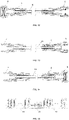
- the manufacturing method includes a production line, the production line set up by the combination of a selected group consisting of extruding station 20, braiding station 30, coating station 40, as shown in FIG. 18 .
- the hose mentioned in embodiment 1-6 can be manufactured by a method which may include in sequence the following steps: a)providing an elastic inner layer formed by extruding; b) elongating 2 times of the stretch yarns with respect to its original length, then twilled weaving with the elongated stretch yarns to form an elastic textile reinforcement layer, and placing the elastic textile reinforcement layer on the elastic inner layer at the same time to obtain a semifinished hose; c) coating an elastic outer layer on the semifinished hose.
- the step b) of placing an elastic textile reinforcement layer includes a step of the one elastic inner layer reciprocally coupling to the inner surface of elongated elastic textile reinforcement layer to obtain a semifinished hose.
- the step c) of coating an elastic outer layer includes a step of the one elastic outer layer and the uncovered surface area of the one elastic inner layer being reciprocally joined to form a unitary tubular member.
- the manufacturing method includes a production line, the production line set up by the combination of a selected group consisting of extruding station 20, braiding station 30, coating station 40, as shown in FIG. 16 .
- the hose mentioned in embodiment 1-6 can be manufactured by a method which may include in sequence the following steps: a)providing an elastic inner layer formed by coating; b) elongating 4 times of the stretch yarns with respect to its original length, then twilled weaving with the elongated stretch yarns to form an elastic textile reinforcement layer, and placing the elastic textile reinforcement layer on the elastic inner layer at the same time to obtain a semifinished hose; c) coating an elastic outer layer on the semifinished hose.
- the step b) of placing an elastic textile reinforcement layer includes a step of the one elastic inner layer reciprocally coupling to the inner surface of elongated elastic textile reinforcement layer to obtain a semifinished hose.
- the step c) of coating an elastic outer layer includes a step of the one elastic outer layer and the uncovered surface area of the one elastic inner layer being reciprocally joined to form a unitary tubular member.
- the manufacturing method includes a production line, the production line set up by the combination of a selected group consisting of extruding station 20, braiding station 30, coating station 40, as shown in FIG. 15 .
- the hose mentioned in embodiment 1-6 can be manufactured by a method which may include in sequence the following steps: a)providing an elastic inner layer formed by coating; b) elongating 7 times of the stretch yarns with respect to its original length, then twilled weaving with the elongated stretch yarns to form an elastic textile reinforcement layer, and placing the elastic textile reinforcement layer on the elastic inner layer at the same time to obtain a semifinished hose; c) extruding an elastic outer layer on the semifinished hose.
- the step b) of placing an elastic textile reinforcement layer includes a step of the one elastic inner layer reciprocally coupling to the inner surface of elongated elastic textile reinforcement layer to obtain a semifinished hose.
- the step c) of extruding an elastic outer layer includes a step of the one elastic outer layer and the uncovered surface area of the one elastic inner layer being reciprocally joined to form a unitary tubular member.
- the manufacturing method includes a production line, the production line set up by the combination of a selected group consisting of extruding station 20, braiding station 30, coating station 40, as shown in FIG. 17 .
- the hose mentioned in embodiment 1-6 can be manufactured by a method which may include in sequence the following steps: a)providing an elastic inner layer formed by extruding; b) elongating 6 times of the stretch yarns with respect to its original length and twilled weaving with the elongated stretch yarns to form an elastic textile reinforcement layer, elongating 6 times of the elastic inner layer with respect to its original length simultaneously, then placing the elongated elastic textile reinforcement layer on the elongated elastic inner layer to obtain a semifinished hose; c) extruding an elastic outer layer on the semifinished hose.
- the step b) of placing an elastic textile reinforcement layer includes a step of the elastic textile reinforcement layer reciprocally coupling to the outer surface of elongated elastic inner layer to obtain a semifinished hose.
- the step c) of extruding an elastic outer layer includes a step of the one elastic outer layer and the uncovered surface area of the one elastic inner layer being reciprocally joined to form a unitary tubular member.
- the manufacturing method includes a production line, the production line set up by the combination of a selected group consisting of extruding station 20, braiding station 30, coating station 40, as shown in FIG. 18 .
- the hose mentioned in embodiment 1-6 can be manufactured by a method which may include in sequence the following steps: a)providing an elastic inner layer formed by extruding; b) elongating 2 times of the stretch yarns with respect to its original length and twilled weaving with the elongated stretch yarns to form an elastic textile reinforcement layer, elongating 2 times of the elastic inner layer with respect to its original length simultaneously, then placing the elongated elastic textile reinforcement layer on the elongated elastic inner layer to obtain a semifinished hose; c) coating an elastic outer layer on the semifinished hose.
- the step b) of placing an elastic textile reinforcement layer includes a step of the elastic textile reinforcement layer reciprocally coupling to the outer surface of elongated elastic inner layer to obtain a semifinished hose.
- the step c) of coating an elastic outer layer includes a step of the one elastic outer layer and the uncovered surface area of the one elastic inner layer being reciprocally joined to form a unitary tubular member.
- the manufacturing method includes a production line, the production line set up by the combination of a selected group consisting of extruding station 20, braiding station 30, coating station 40, as shown in FIG. 16 .
- the hose mentioned in embodiment 1-6 can be manufactured by a method which may include in sequence the following steps: a)providing an elastic inner layer formed by coating; b) elongating 4 times of the stretch yarns with respect to its original length and twilled weaving with the elongated stretch yarns to form an elastic textile reinforcement layer, elongating 4 times of the elastic inner layer with respect to its original length simultaneously, then placing the elongated elastic textile reinforcement layer on the elongated elastic inner layer to obtain a semifinished hose; c) coating an elastic outer layer on the semifinished hose.
- the step b) of placing an elastic textile reinforcement layer includes a step of the elastic textile reinforcement layer reciprocally coupling to the outer surface of elongated elastic inner layer to obtain a semifinished hose.
- the step c) of coating an elastic outer layer includes a step of the one elastic outer layer and the uncovered surface area of the one elastic inner layer being reciprocally joined to form a unitary tubular member.
- the manufacturing method includes a production line, the production line set up by the combination of a selected group consisting of extruding station 20, braiding station 30, coating station 40, as shown in FIG. 15 .
- the hose mentioned in embodiment 1-6 can be manufactured by a method which may include in sequence the following steps: a)providing an elastic inner layer formed by coating; b) elongating 7 times of the stretch yarns with respect to its original length and twilled weaving with the elongated stretch yarns to form an elastic textile reinforcement layer, elongating 7 times of the elastic inner layer with respect to its original length simultaneously, then placing the elongated elastic textile reinforcement layer on the elongated elastic inner layer to obtain a semifinished hose; c) extruding an elastic outer layer on the semifinished hose.
- the step b) of placing an elastic textile reinforcement layer includes a step of the elastic textile reinforcement layer reciprocally coupling to the outer surface of elongated elastic inner layer to obtain a semifinished hose.
- the step c) of extruding an elastic outer layer includes a step of the one elastic outer layer and the uncovered surface area of the one elastic inner layer being reciprocally joined to form a unitary tubular member.
- the manufacturing method includes a production line, the production line set up by the combination of a selected group consisting of extruding station 20, braiding station 30, coating station 40, as shown in FIG. 17 .
- An extensible flexible hose comprises one elastic inner layer 1, one elastic textile reinforcement layer 2 and one elastic outer layer 3, where the elastic textile reinforcement layer placed on the outer surface of the elastic inner layer, the elastic outer layer disposed on the elastic textile reinforcement layer, while the elastic inner layer and the elastic textile reinforcement layer are reciprocally coupled, the elastic outer layer and the uncovered surface area of the elastic inner layer are reciprocally joined to form a unitary tubular member 10.
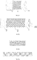
- the elastic textile reinforcement layer is formed by a twill weave textile layer 21, as shown in FIG. 21-24 .
- the twill weave textile layer is prepared by twilled weaving, while said stretch yarns being parallelly woven in between.
- the elastic textile reinforcement layer has an axial elasticity and a radial constraint force, that allows the elastic textile reinforcement layer automatically elongating and restricts the elastic textile reinforcement layer from automatically enlarging under working pressure given by a liquid flowing therethrough.
- the elastic textile reinforcement layer increases its length of 4.6 times with respect to its original length under working pressure of 6 bar.
- the elastic textile reinforcement layer increases its length of at maximum 7 times with respect to its original length under working pressure, and the elastic textile reinforcement layer also can withstand a working pressure of 8 bar, which has a relatively high burst pressure.
- the twill weave textile layer being made of polypropylene, while the yarn counts of the material using in the twill weave textile layer is 800D.
- the elastic inner layer is made of thermoplastic elastomer material, and the inner diameter of the elastic inner layer is 6mm, and the external diameter of the elastic inner layer is 9mm, and the thickness of the elastic inner layer is 1.5mm.
- the elastic outer layer is made of thermoplastic elastomer material, and the thickness of the elastic outer layer is 1mm.
- two ends of the unitary tubular member are respectively provided with a joint 4, the joint comprises a convex connector 41, a pawl type snap joint 42, and a locking piece 43.
- the convex connector inserted into the end of the unitary tubular member, the pawl type snap joint connected to the exterior of the unitary tubular member, the locking piece fastened on the exterior of the pawl type snap joint.
- the joint also has a through-hole 44 within, which can connect to the inner space of elastic inner layer.
- the convex connector being a hollow structural connector, comprises a body part 411, a convex part 412, a spacing part 413, a screw thread part 414.
- the body part connected with the convex part, the end of the convex part connected with the spacing part, the screw thread part set on the exterior of the body part, the screw thread part also connected with the locking piece.
- the joint designed to be removably connected with the unitary tubular member, while the spacing part can prevent the elastic inner layer from moving away.
- the joint provided with one of the following connector structures at an end away from the unitary tubular member: a quick-connect connection structure 5, an internally threaded joint structure 6 or an externally threaded joint structure 7.
- An extensible flexible hose comprises one elastic inner layer 1, one elastic textile reinforcement layer 2 and one elastic outer layer 3, where the elastic textile reinforcement layer placed on the outer surface of the elastic inner layer, the elastic outer layer disposed on the elastic textile reinforcement layer, while the elastic inner layer and the elastic textile reinforcement layer are reciprocally coupled, the elastic outer layer and the uncovered surface area of the elastic inner layer are reciprocally joined to form a unitary tubular member 10.
- the elastic textile reinforcement layer is formed by a twill weave textile layer 21, as shown in FIG. 21-24 .
- the twill weave textile layer is prepared by twilled weaving, while said stretch yarns being parallelly woven in between.
- the elastic textile reinforcement layer has an axial elasticity and a radial constraint force, that allows the elastic textile reinforcement layer automatically elongating and restricts the elastic textile reinforcement layer from automatically enlarging under working pressure given by a liquid flowing therethrough.
- the elastic textile reinforcement layer increases its length of 3 times with respect to its original length under working pressure of 8 bar.
- the elastic textile reinforcement layer increases its length of at maximum 4.5 times with respect to its original length under working pressure, and the elastic textile reinforcement layer also can withstand a working pressure of 10 bar, which has a relatively high burst pressure.
- the twill weave textile layer being made of polyester, while the yarn counts of the material using in the twill weave textile layer is 600D.
- the elastic inner layer is made of thermoplastic elastomer material, and the inner diameter of the elastic inner layer is 9mm, and the external diameter of the elastic inner layer is 12mm, and the thickness of the elastic inner layer is 1.5mm.
- the elastic outer layer is made of thermoplastic elastomer material, and the thickness of the elastic outer layer is 2mm.
- two ends of the unitary tubular member are respectively provided with a joint 4, the joint comprises a convex connector 41, a pawl type snap joint 42, and a locking piece 43.
- the convex connector inserted into the end of the unitary tubular member, the pawl type snap joint connected to the exterior of the unitary tubular member, the locking piece fastened on the exterior of the pawl type snap joint.
- the joint also has a through-hole 44 within, which can connect to the inner space of elastic inner layer.
- the convex connector being a hollow structural connector, comprises a body part 411, a convex part 412, a spacing part 413, a screw thread part 414.
- the body part connected with the convex part, the end of the convex part connected with the spacing part, the screw thread part set on the exterior of the body part, the screw thread part also connected with the locking piece.
- the joint designed to be removably connected with the unitary tubular member, while the spacing part can prevent the elastic inner layer from moving away.
- the joint provided with one of the following connector structures at an end away from the unitary tubular member: a quick-connect connection structure 5, an internally threaded joint structure 6 or an externally threaded joint structure 7.
- An extensible flexible hose comprises one elastic inner layer 1, one elastic textile reinforcement layer 2 and one elastic outer layer 3, where the elastic textile reinforcement layer placed on the outer surface of the elastic inner layer, the elastic outer layer disposed on the elastic textile reinforcement layer, while the elastic inner layer and the elastic textile reinforcement layer are reciprocally coupled, the elastic outer layer and the uncovered surface area of the elastic inner layer are reciprocally joined to form a unitary tubular member 10.
- the elastic textile reinforcement layer is formed by a twill weave textile layer 21, as shown in FIG. 21-24 .
- the twill weave textile layer is prepared by twilled weaving, while said stretch yarns being parallelly woven in between.
- the elastic textile reinforcement layer has an axial elasticity and a radial constraint force, that allows the elastic textile reinforcement layer automatically elongating and restricts the elastic textile reinforcement layer from automatically enlarging under working pressure given by a liquid flowing therethrough.
- the elastic textile reinforcement layer increases its length of 1.8 times with respect to its original length under working pressure of 15 bar.
- the elastic textile reinforcement layer increases its length of at maximum 3 times with respect to its original length under working pressure, and the elastic textile reinforcement layer also can withstand a working pressure of 30 bar, which has a relatively high burst pressure.
- the twill weave textile layer being made of nylon, while the yarn counts of the material using in the twill weave textile layer is 3000D.
- the elastic inner layer is made of rubber material, and the inner diameter of the elastic inner layer is 20mm, and the external diameter of the elastic inner layer is 30mm, and the thickness of the elastic inner layer is 5mm.
- the elastic outer layer is made of rubber material, and the thickness of the elastic outer layer is 4mm.
- two ends of the unitary tubular member are respectively provided with a joint 4, the joint comprises a convex connector 41, a pawl type snap joint 42, and a locking piece 43.
- the convex connector inserted into the end of the unitary tubular member, the pawl type snap joint connected to the exterior of the unitary tubular member, the locking piece fastened on the exterior of the pawl type snap joint.
- the joint also has a through-hole 44 within, which can connect to the inner space of elastic inner layer.
- the convex connector being a hollow structural connector, comprises a body part 411, a convex part 412, a spacing part 413, a screw thread part 414.
- the body part connected with the convex part, the end of the convex part connected with the spacing part, the screw thread part set on the exterior of the body part, the screw thread part also connected with the locking piece.
- the joint designed to be removably connected with the unitary tubular member, while the spacing part can prevent the elastic inner layer from moving away.
- the joint provided with one of the following connector structures at an end away from the unitary tubular member: a quick-connect connection structure 5, an internally threaded joint structure 6 or an externally threaded joint structure 7.
- An extensible flexible hose comprises one elastic inner layer 1, one elastic textile reinforcement layer 2 and one elastic outer layer 3, where the elastic textile reinforcement layer placed on the outer surface of the elastic inner layer, the elastic outer layer disposed on the elastic textile reinforcement layer, while the elastic inner layer and the elastic textile reinforcement layer are reciprocally coupled, the elastic outer layer and the uncovered surface area of the elastic inner layer are reciprocally joined to form a unitary tubular member 10.
- the elastic textile reinforcement layer is formed by a twill weave textile layer 21, as shown in FIG. 21-24 .
- the twill weave textile layer is prepared by twilled weaving, while said stretch yarns being parallelly woven in between.
- the elastic textile reinforcement layer has an axial elasticity and a radial constraint force, that allows the elastic textile reinforcement layer automatically elongating and restricts the elastic textile reinforcement layer from automatically enlarging under working pressure given by a liquid flowing therethrough.
- the elastic textile reinforcement layer increases its length of 2.5 times with respect to its original length under working pressure of 10 bar.
- the elastic textile reinforcement layer increases its length of at maximum 4 times with respect to its original length under working pressure, and the elastic textile reinforcement layer also can withstand a working pressure of 20 bar, which has a relatively high burst pressure.
- the twill weave textile layer being made of acrylic fibres, while the yarn counts of the material using in the twill weave textile layer is 1000D.
- the elastic inner layer is made of rubber material, and the inner diameter of the elastic inner layer is 12mm, and the external diameter of the elastic inner layer is 16mm, and the thickness of the elastic inner layer is 2mm.
- the elastic outer layer is made of rubber material, and the thickness of the elastic outer layer is 2mm.
- two ends of the unitary tubular member are respectively provided with a joint 4, the joint comprises a convex connector 41, a pawl type snap joint 42, and a locking piece 43.
- the convex connector inserted into the end of the unitary tubular member, the pawl type snap joint connected to the exterior of the unitary tubular member, the locking piece fastened on the exterior of the pawl type snap joint.
- the joint also has a through-hole 44 within, which can connect to the inner space of elastic inner layer.
- the convex connector being a hollow structural connector, comprises a body part 411, a convex part 412, a spacing part 413, a screw thread part 414.
- the body part connected with the convex part, the end of the convex part connected with the spacing part, the screw thread part set on the exterior of the body part, the screw thread part also connected with the locking piece.
- the joint designed to be removably connected with the unitary tubular member, while the spacing part can prevent the elastic inner layer from moving away.
- the joint provided with one of the following connector structures at an end away from the unitary tubular member: a quick-connect connection structure 5, an internally threaded joint structure 6 or an externally threaded joint structure 7.
- An extensible flexible hose comprises one elastic inner layer 1, one elastic textile reinforcement layer 2 and one elastic outer layer 3, where the elastic textile reinforcement layer placed on the outer surface of the elastic inner layer, the elastic outer layer disposed on the elastic textile reinforcement layer, while the elastic inner layer and the elastic textile reinforcement layer are reciprocally coupled, the elastic outer layer and the uncovered surface area of the elastic inner layer are reciprocally joined to form a unitary tubular member 10.
- the elastic textile reinforcement layer is formed by a twill weave textile layer 21, as shown in FIG. 21-24 .
- the twill weave textile layer is prepared by twilled weaving, while said stretch yarns being parallelly woven in between.
- the elastic textile reinforcement layer has an axial elasticity and a radial constraint force, that allows the elastic textile reinforcement layer automatically elongating and restricts the elastic textile reinforcement layer from automatically enlarging under working pressure given by a liquid flowing therethrough.
- the elastic textile reinforcement layer increases its length of 1.5 times with respect to its original length under working pressure of 7 bar.
- the elastic textile reinforcement layer increases its length of at maximum 2.5 times with respect to its original length under working pressure, and the elastic textile reinforcement layer also can withstand a working pressure of 15 bar, which has a relatively high burst pressure.
- the twill weave textile layer being made of polypropylene, while the yarn counts of the material using in the twill weave textile layer is 5000D.
- the elastic inner layer is made of thermoplastic elastomer material, and the inner diameter of the elastic inner layer is 72mm, and the external diameter of the elastic inner layer is 86mm, and the thickness of the elastic inner layer is 8mm.
- the elastic outer layer is made of rubber material, and the thickness of the elastic outer layer is 5mm.
- two ends of the unitary tubular member are respectively provided with a joint 4, the joint comprises a convex connector 41, a pawl type snap joint 42, and a locking piece 43.
- the convex connector inserted into the end of the unitary tubular member, the pawl type snap joint connected to the exterior of the unitary tubular member, the locking piece fastened on the exterior of the pawl type snap joint.
- the joint also has a through-hole 44 within, which can connect to the inner space of elastic inner layer.
- the convex connector being a hollow structural connector, comprises a body part 411, a convex part 412, a spacing part 413, a screw thread part 414.
- the body part connected with the convex part, the end of the convex part connected with the spacing part, the screw thread part set on the exterior of the body part, the screw thread part also connected with the locking piece.
- the joint designed to be removably connected with the unitary tubular member, while the spacing part can prevent the elastic inner layer from moving away.
- the joint provided with one of the following connector structures at an end away from the unitary tubular member: a quick-connect connection structure 5, an internally threaded joint structure 6 or an externally threaded joint structure 7.
- An extensible flexible hose comprises one elastic inner layer 1, one elastic textile reinforcement layer 2 and one elastic outer layer 3, where the elastic textile reinforcement layer placed on the outer surface of the elastic inner layer, the elastic outer layer disposed on the elastic textile reinforcement layer, while the elastic inner layer and the elastic textile reinforcement layer are reciprocally coupled, the elastic outer layer and the uncovered surface area of the elastic inner layer are reciprocally joined to form a unitary tubular member 10.
- the elastic textile reinforcement layer is formed by a twill weave textile layer 21, as shown in FIG. 21-24 .
- the twill weave textile layer is prepared by twilled weaving, and the elastic textile reinforcement layer has an axial elasticity and a radial constraint force, that allows the elastic textile reinforcement layer automatically elongating and restricts the elastic textile reinforcement layer from automatically enlarging under working pressure given by a liquid flowing therethrough.
- the elastic textile reinforcement layer increases its length of 3.5 times with respect to its original length under working pressure of 15 bar.
- the elastic textile reinforcement layer increases its length of at maximum 5.5times with respect to its original length under working pressure, and the elastic textile reinforcement layer also can withstand a working pressure of 25 bar, which has a relatively high burst pressure.
- the twill weave textile layer being made of nylon, while the yarn counts of the material using in the twill weave textile layer is 500D.
- the elastic inner layer is made of rubber material, and the inner diameter of the elastic inner layer is 40mm, and the external diameter of the elastic inner layer is 52mm, and the thickness of the elastic inner layer is 6mm.
- the elastic outer layer is made of thermoplastic elastomer material, and the thickness of the elastic outer layer is 5mm.
- two ends of the unitary tubular member are respectively provided with a joint 4, the joint comprises a convex connector 41, a pawl type snap joint 42, and a locking piece 43.
- the convex connector inserted into the end of the unitary tubular member, the pawl type snap joint connected to the exterior of the unitary tubular member, the locking piece fastened on the exterior of the pawl type snap joint.
- the joint also has a through-hole 44 within, which can connect to the inner space of elastic inner layer.
- the convex connector being a hollow structural connector, comprises a body part 411, a convex part 412, a spacing part 413, a screw thread part 414.
- the body part connected with the convex part, the end of the convex part connected with the spacing part, the screw thread part set on the exterior of the body part, the screw thread part also connected with the locking piece.
- the joint designed to be removably connected with the unitary tubular member, while the spacing part can prevent the elastic inner layer from moving away.
- the joint provided with one of the following connector structures at an end away from the unitary tubular member: a quick-connect connection structure 5, an internally threaded joint structure 6 or an externally threaded joint structure 7.
- the hose mentioned in embodiment 15-20 can be manufactured by a method which may include in sequence the following steps: a)providing an elastic inner layer formed by extruding; b) elongating 6 times of the elastic inner layer with respect to its original length, and placing an elastic textile reinforcement layer on the elongated elastic inner layer to obtain a semifinished hose; c) extruding an elastic outer layer on the semifinished hose.
- the step b) of placing an elastic textile reinforcement layer includes a step of the elastic textile reinforcement layer reciprocally coupling to the outer surface of elongated elastic inner layer to obtain a semifinished hose.
- the step c) of extruding an elastic outer layer includes a step of the one elastic outer layer and the uncovered surface area of the one elastic inner layer being reciprocally joined to form a unitary tubular member.
- the manufacturing method includes a production line, the production line set up by the combination of a selected group consisting of extruding station 20, braiding station 30, coating station 40, as shown in FIG. 18 .
- the hose mentioned in embodiment 15-20 can be manufactured by a method which may include in sequence the following steps: a)providing an elastic inner layer formed by extruding; b) elongating 2 times of the elastic inner layer with respect to its original length, and placing an elastic textile reinforcement layer on the elongated elastic inner layer to obtain a semifinished hose; c) coating an elastic outer layer on the semifinished hose.
- the step b) of placing an elastic textile reinforcement layer includes a step of the elastic textile reinforcement layer reciprocally coupling to the outer surface of elongated elastic inner layer to obtain a semifinished hose.
- the step c) of coating an elastic outer layer includes a step of the one elastic outer layer and the uncovered surface area of the one elastic inner layer being reciprocally joined to form a unitary tubular member.
- the manufacturing method includes a production line, the production line set up by the combination of a selected group consisting of extruding station 20, braiding station 30, coating station 40, as shown in FIG. 16 .
- the hose mentioned in embodiment 15-20 can be manufactured by a method which may include in sequence the following steps: a)providing an elastic inner layer formed by coating; b) elongating 4 times of the elastic inner layer with respect to its original length, and placing an elastic textile reinforcement layer on the elongated elastic inner layer to obtain a semifinished hose; c) coating an elastic outer layer on the semifinished hose.
- the step b) of placing an elastic textile reinforcement layer includes a step of the elastic textile reinforcement layer reciprocally coupling to the outer surface of elongated elastic inner layer to obtain a semifinished hose.
- the step c) of coating an elastic outer layer includes a step of the one elastic outer layer and the uncovered surface area of the one elastic inner layer being reciprocally joined to form a unitary tubular member.
- the manufacturing method includes a production line, the production line set up by the combination of a selected group consisting of extruding station 20, braiding station 30, coating station 40, as shown in FIG. 15 .
- the hose mentioned in embodiment 15-20 can be manufactured by a method which may include in sequence the following steps: a)providing an elastic inner layer formed by coating; b) elongating 7 times of the elastic inner layer with respect to its original length, and placing an elastic textile reinforcement layer on the elongated elastic inner layer to obtain a semifinished hose; c) extruding an elastic outer layer on the semifinished hose.
- the step b) of placing an elastic textile reinforcement layer includes a step of the elastic textile reinforcement layer reciprocally coupling to the outer surface of elongated elastic inner layer to obtain a semifinished hose.
- the step c) of extruding an elastic outer layer includes a step of the one elastic outer layer and the uncovered surface area of the one elastic inner layer being reciprocally joined to form a unitary tubular member.
- the manufacturing method includes a production line, the production line set up by the combination of a selected group consisting of extruding station 20, braiding station 30, coating station 40, as shown in FIG. 17 .
Description
- The present invention relates to the technical field of telescopic water pipes, and in particular to an extensible flexible hose, and method for manufacturing thereof.
-
WO 2016/098063 A1 describes a hose comprising at least one inner layer and one outer layer made of elastic polymeric material, and at least one textile reinforcement layer interposed between said at least one inner and outer layers. The inner layer and the outer layer are reciprocally coupled to form a unitary tubular member internally to which the textile reinforcement layer is embedded. The unitary tubular member has an elasticity such to automatically elongate upon the working pressure given by the liquid flowing therethrough to increase its original length and such to automatically recover once the working pressure stops. The textile reinforcement layer is susceptible to move from a rest configuration that has when the working pressure stops to a working configuration that has when said unitary tubular member elongates upon the working pressure and vice-versa. -
WO 2017/187233 A1 describes a flexible hose for transporting fluid. The hose comprises at least one inner layer made of a first elastic polymeric material, at least one outer layer made of a second elastic polymeric material, at least one textile reinforcement layer interposed between said at least one inner layer and at least one outer layer. The at least one inner layer and the at least one outer layer are reciprocally coupled to form a unitary tubular member internally to which the at least one textile reinforcement layer is embedded. The unitary tubular member has an elasticity such to automatically enlarge upon the working pressure given by the liquid flowing therethrough to increase its original diameter and such to automatically recovery once the working pressure stops for assuming again the original diameter. The at least one textile reinforcement layer is susceptible to move from a rest configuration that has when the working pressure stops to a working configuration that has when said unitary tubular member enlarges upon the working pressure and vice-versa. -
US 2016/0245430 A1 describes a flexible hose for transporting a fluid, including an outer sheath and an inner tube. The inner tube has an inner layer made of a first elastic polymeric material and an outer layer made of a second elastic polymeric material with a textile reinforcement layer embedded within the inner tube to form a unitary tubular member. The elasticity of the unitary tubular member is such that it automatically elongates under the working pressure provided by a liquid flowing therethrough and automatically recovers its original length when the working pressure stops. The textile reinforcement layer is adapted to move from a rest configuration when there is no working pressure, to a working configuration when the unitary tubular member elongates under the working pressure. - Currently, the existing telescopic water pipe on the market, mostly consist of inner core elastic tube and outer sheath, is an elastic tube, made of latex, rubber or a TPR thermoplastic elastomer as a raw material. Due to the high elasticity of the telescopic water pipe, when the telescopic water pipe is connected with 3-10 kg of pressurized water, under the protection by the outer sheath, the radial water-passing area and longitudinal length of the telescopic water pipe can be expanded to extend by 2-4 times; and when the pressurized water source is turned off, under the resilience force of the inner core elastic tube, the telescopic water pipe quickly discharges the residual water in the pipe and retracts to the original product size. Therefore, the telescopic water pipe is easy to use and is very popular among customers at home and abroad. However, the service life of the telescopic water pipe on the market is too low to meet people's expectations, also not convenient to store and easily stain the outer sheath.
- Through detailed market research, it shows that 70% of the damage of the telescopic water pipe in use caused by strong friction between the inner tube and the outer sheath. To be specific, with the rapid expansion of the elastic tube after the telescopic water pipe connected with pressurized water, strong friction occurred between the inner tube and the outer sheath, and it caused another strong friction between the inner tube and the outer sheath when the pressurized water source disconnected. It also caused critical damage to the elastic tube in the process of use, while foreign particles such as sand grains enter the inner tube after passing through the outer sheath during stretch and retraction.
- To solve the above defects, engineering technicians have made a lot of explorations, for example,
Chinese patent No. 201320166720.6 - To counter the problems above,
Chinese patent No. 201520897299.5 - To further solve the above problems,
Chinese patent No. 201720093703.2 US20180299038A1 discloses a telescopic water pipe with two-layer woven structure, including an inner layer and an outer layer made of an elastic polymeric material, and a first and second textile reinforcement layers which could stretch axially and radially interposed between the inner and the outer layers. To do so, the radial expansion the extensible flexible hose can be controlled and the longitudinal length of the telescopic water pipe can have a maximum 2.5 times elongation with respect to its original length, which could prolong the longitudinal length of the telescopic water pipe effectively. However, the textile reinforcement layers mainly contribute to the restriction of the expansion and determines the elongation of the hose as well, which decreases the elasticity of the flexible hose, and the manufacturing process of the hose is intricate. Also, the two textile reinforcement layers likely could break the connection within the hose, causing local overexpansion, that could break the unity of the flexible hose and lower its service life. - Therefore, it is an urgent problem to be solved by those skilled in the art how to change the current situation in which the telescopic water pipe is liable to be broken due to abrasion, stress, and the like in the prior art, and to prolong the service life of the telescopic water pipe, to make it simple and practical to be stored.
- An objective of the present invention is to provide an extensible flexible hose and method for manufacturing thereof, so as to solve the above problems existed in the prior art, to improve the phenomenon that the telescopic water pipe is liable to be damaged due to strong friction between inner core and outer sheath, to prolong the service life of the extensible flexible hose. The whole hose body is made of elastic materials, which changed the structure of traditional hose, having advantages as great elasticity, easy to carry, simple to clean, and convenient to store.
- To achieve the above objective, the present invention provides the following solution, wherein the scope of protection is defined by the appended claims:
An extensible flexible hose comprises one elastic inner layer, one elastic textile reinforcement layer and one elastic outer layer, where the elastic textile reinforcement layer placed on the outer surface of the elastic inner layer, the elastic outer layer disposed on the elastic textile reinforcement layer, while the elastic inner layer and the elastic textile reinforcement layer are reciprocally coupled, the elastic outer layer and the uncovered surface area of the elastic inner layer are reciprocally joined to form a unitary tubular member. In other words, the one elastic outer layer and the one elastic inner layer may be reciprocally joined except at the regions occupied by the elastic textile reinforcement layer. The elastic textile reinforcement layer comprising a twill weave textile layer, with stretch yarns longitudinally distributed among, wherein said twill weave textile layer is prepared by twilled weaving, while said stretch yarns being parallelly woven in between. - The integrated combination of elastic inner layer, elastic textile reinforcement layer and elastic outer layer, providing a tubular member features with minimum bulkiness and compact structure, which changes the traditional flexible hose with the structure of the inner core and the outer sheath being separated. With the elasticity of the whole hoes body, it guarantees the hose could increasing its length of at maximum 5 times with respect to its original length under working pressure and retracting fast once the working pressure stops, which increases the working efficiency significantly.
- Preferably, the elastic textile reinforcement layer has an axial elasticity and a radial constraint force, that allows the elastic textile reinforcement layer automatically elongating and restricts the elastic textile reinforcement layer from automatically enlarging under working pressure given by a liquid flowing therethrough.
- Preferably, the elastic textile reinforcement layer increases its length of at maximum 7 times with respect to its original length under working pressure, and the elastic textile reinforcement layer also can withstand a working pressure of 8 to 30 bar, which has a relatively high burst pressure.
- Preferably, the number of the stretch yarns among the elastic textile reinforcement layer ranges from 8 to 96, the diameter of the stretch yarn ranges from 0.25mm to 2mm.
- Preferably, the twill weave textile layer being made of in a material selected among the group consisting of polyester, polypropylene, nylon and acrylic fibres, while the yarn counts of the material using in the twill weave textile layer ranges from 10D to 5000D.
- The twill weave textile layer is made of elastic materials and fiber materials, being prepared by twilled weaving, could restraining the radial enlargement but to yield in axial direction with the combined effect of the stretch yarns, further restricting the motion of both elastic inner layer and elastic outer layer to increase the utilization rate and to prolong the service life the extensible flexible hose.
- Preferably, the elastic inner layer is made of thermoplastic elastomer material or rubber material, and the inner diameter of the elastic inner layer ranges from 3mm to 95mm, and the external diameter of the elastic inner layer ranges from 3.2mm to 100mm, and the thickness of the elastic inner layer ranges from 0.2mm to 10mm.
- Preferably, the elastic outer layer is made of thermoplastic elastomer material or rubber material, and the thickness of the elastic outer layer ranges from 0.2mm to 10mm.
- The elastic outer layer is processed by extrusion or coating process that could guarantee the tight junction between the elastic outer layer and the other two layers. On one hand, the elastic outer layer can effectively prevent small hard objects (e.g., grains of sand) entering the elastic textile reinforcement layer which could cause burst of elastic inner layer during the friction between the elastic textile reinforcement layer and the elastic inner layer to reduce its service life. On the other hand, the elastic inner layer and elastic textile reinforcement layer can be further joined due to existence of the elastic outer layer, which can guarantee the synchronous telescoping of the unitary tubular member and reduce the friction between the elastic textile reinforcement layer and elastic inner layer, can prolong the service life of stretch yarns. Meanwhile, the elastic outer layer also gives the hose a minimum bulkiness and compact structure that can contribute to a higher elongation and better elasticity, can further increase the working efficiency of the hose. Besides, the elastic outer layer is simple to clean and practical to be stored.
- As used herein, with the expression "twill weave textile layer" is meant a layer consisting of at least two yarns or groups of yarns laying on a supporting layer with opposite inclinations and connected to one another alternately to form a weave. In a weaving process, one yarn is interlaced with another yarn once above and then below the latter.
- Advantageously, the elastic textile reinforcement layer of the extensible hose of the present invention may be susceptible to move between a rest configuration that has at rest, i.e. when the liquid does not flow through the unitary tubular member, and a working configuration that has when the unitary tubular member is actuated by the working pressure of the liquid flowing therethrough.
- In the working configuration the elastic textile reinforcement layer only extends axially to accompany the elongation of the unitary tubular member.
- In other words, for a given inner hose pressure the maximum axial elongation of the elastic textile reinforcement layer is the same as the maximum axial elongation of the unitary tubular member.
- Preferably, two ends of the unitary tubular member are respectively provided with a joint, the joint comprises a convex connector, a pawl type snap joint, and a locking piece. The convex connector inserted into the end of the unitary tubular member, the pawl type snap joint connected to the exterior of the unitary tubular member, the locking piece fastened on the exterior of the pawl type snap joint.
- The convex connector being a hollow structural connector, comprises a body part, a convex part, a spacing part, a screw thread part. The body part connected with the convex part, the end of the convex part connected with the spacing part, the screw thread part set on the exterior of the body part, the screw thread part also connected with the locking piece. The joint designed to be removably connected with the unitary tubular member, while the spacing part can prevent the elastic inner layer from moving away. With the combined effect of locking piece and convex connector, the elastic inner layer could be connected tightly on the exterior of the convex part, making sure the tubular member stay within the joint under working pressure.
- Preferably, the joint provided with one of the following connector structures at an end away from the unitary tubular member: a quick-connect connection structure, an internally threaded joint structure or an externally threaded joint structure.
- The hose can be manufactured by a method which may include in sequence the following steps: a)providing an elastic inner layer formed by extruding or coating; b) elongating between 2 to 7 times of the elastic inner layer with respect to its original length, and placing an elastic textile reinforcement layer on the elongated elastic inner layer to obtain a semifinished hose; c) extruding or coating an elastic outer layer on the semifinished hose.
- Preferably, the step b) of placing an elastic textile reinforcement layer includes a step of the elastic textile reinforcement layer reciprocally coupling to the outer surface of elongated elastic inner layer to obtain a semifinished hose.
- Preferably, the step c) of extruding or coating an elastic outer layer includes a step of the one elastic outer layer and the uncovered surface area of the one elastic inner layer being reciprocally joined to form a unitary tubular member.
- Preferably, the manufacturing method includes a production line, the production line set up by the combination of a selected group consisting of extruding station, braiding station, coating station.
- Advantageously, the elastic inner layer formed by an extruding station or a coating station, and the elastic textile reinforcement layer placed on the outer surface of the elongated elastic inner layer by braiding station to obtain a semifinished hose, then the elastic outer layer extruding or coating on the semifinished hose by extruding station or coating station respectively to form a unitary tubular member.
- Must be noted that, methods and equipment of manufacturing in the prior art can be used to produce the hose in this invention. For instance, an example of coating process is known from document
CN Pat. No. 2016107644189 CN Pat. No. 2011104581255 CN Pat. No. 2018201633039 CN Pat. No. 2016201292321 CN Pat. No. 2017203694193 CN Pat. No. 2006100134459 - In a preferred embodiment of the invention, the hose comprises one elastic inner layer, one elastic textile reinforcement layer and one elastic outer layer, where the elastic textile reinforcement layer placed on the outer surface of the elastic inner layer, the elastic outer layer disposed on the elastic textile reinforcement layer, while the elastic inner layer and the elastic textile reinforcement layer are reciprocally coupled, the elastic outer layer and the uncovered surface area of the elastic inner layer are reciprocally joined to form a unitary tubular member. The elastic textile reinforcement layer is formed by a twill weave textile layer.
- In a preferred embodiment of the invention, the hose can be manufactured by a method which may include in sequence the following steps: a)providing an elastic inner layer formed by extruding or coating; b) elongating between 2 to 7 times of the stretch yarns with respect to its original length, then twilled weaving with the elongated stretch yarns to form an elastic textile reinforcement layer, and placing the elastic textile reinforcement layer on the elastic inner layer at the same time to obtain a semifinished hose; c) extruding or coating an elastic outer layer on the semifinished hose.
- Preferably, the step b) of placing an elastic textile reinforcement layer includes a step of the one elastic inner layer reciprocally coupling to the inner surface of elongated elastic textile reinforcement layer to obtain a semifinished hose.
- Preferably, the step c) of extruding or coating an elastic outer layer includes a step of the one elastic outer layer and the uncovered surface area of the one elastic inner layer being reciprocally joined to form a unitary tubular member.
- Preferably, the manufacturing method includes a production line, the production line set up by the combination of a selected group consisting of extruding station, braiding station, coating station.
- Advantageously, the elastic inner layer formed by an extruding station or a coating station, and the elastic textile reinforcement layer disposed on the elastic inner layer by braiding station to obtain a semifinished hose, then the elastic outer layer extruding or coating on the semifinished hose by extruding station or coating station respectively to form a unitary tubular member.
- Thanks to one or more of the above features, the above extendable hose can be manufactured in a simple and fast manner. In fact, the extensible hose can be manufactured automatically in line, without the aid of human operators.
- The present invention provides an extensible flexible hose with an integrated tubular member form, which changes the traditional flexible hose with structure of the inner core and the outer sheath being separated, had overcome the disadvantage of short service life due to strong friction between the inner core and outer sheath of the traditional hose. Besides, with the elasticity of the whole hoes body and the disposition of elastic textile reinforcement layer, it guarantees the hose could increase its length of at
maximum 5 times with respect to its original length under working pressure and retracting fast once the working pressure stops, which increases the working efficiency significantly and makes it convenient to store. Moreover, the elastic outer layer is made of thermoplastic elastomer material or rubber material, which makes it simple to clean. - The present invention also provides a production line set up by the combination of a selected group consisting of extruding station, braiding station, coating station, which can adjust to various manufacturing conditions, has advantages as low operation cost, simple process, etc.
-
-
FIGS. 1 is a schematic view of an embodiment of the hose at rest; -
FIGS. 2 is a schematic view of an embodiment of the hose under pressure; -
FIGS. 3 is a schematic view of an embodiment of the hose during use; -
FIGS. 4 is a schematic view of an embodiment of the hose during use; -
FIGS. 5 is a schematic view of an embodiment of the hose during use; -
FIG. 6 is a radial sectional view of the embodiment of the hose; -
FIG. 7 is a radial sectional view of the embodiment of the hose; -
FIG. 8 is a radial sectional view of the embodiment of the hose; -
FIGS. 9 is a schematic view of an embodiment of the hose connected with connector structures; -
FIGS. 10 is a schematic view of an embodiment of the hose connected with connector structures; -
FIGS. 11 is a schematic view of an embodiment of the hose connected with connector structures; -
FIGS. 12 is a schematic view of an embodiment of the hose connected with connector structures; -
FIGS. 13 is a schematic view of an embodiment of the hose connected with connector structures; -
FIGS. 14 is a schematic view of an embodiment of the hose connected with connector structures; -
FIGS. 15 is a schematic side view of an embodiment of the production line; -
FIGS. 16 is a schematic side view of an embodiment of the production line; -
FIGS. 17 is a schematic side view of an embodiment of the production line; -
FIGS. 18 is a schematic side view of an embodiment of the production line; -
FIGS. 19 is a schematic side view of an embodiment of elastic textile reinforcement layer at rest; -
FIGS. 20 is a schematic side view of an embodiment of elastic textile reinforcement layer under pressure; -
FIGS. 21 is a schematic view of an embodiment of the hose at rest; -
FIGS. 22 is a schematic view of an embodiment of the hose under pressure; -
FIGS. 23 is a schematic side view of an embodiment of elastic textile reinforcement layer at rest; -
FIGS. 24 is a schematic side view of an embodiment of elastic textile reinforcement layer under pressure. - The present invention will be described hereinafter with reference to the embodiments, from which the technical solutions will be clear and complete. Obviously, the described embodiments constitute only a part of the embodiments of the present invention, but not all of the embodiments.
- An extensible flexible hose comprises one elastic
inner layer 1, one elastictextile reinforcement layer 2 and one elasticouter layer 3, where the elastic textile reinforcement layer placed on the outer surface of the elastic inner layer, the elastic outer layer disposed on the elastic textile reinforcement layer, while the elastic inner layer and the elastic textile reinforcement layer are reciprocally coupled, the elastic outer layer and the uncovered surface area of the elastic inner layer are reciprocally joined to form aunitary tubular member 10. In other words, the one elastic outer layer and the one elastic inner layer may be reciprocally joined except at the regions occupied by the elastic textile reinforcement layer. The elastic textile reinforcement layer comprising a twillweave textile layer 21, withstretch yarns 22 longitudinally distributed among, as shown inFIG. 1-2 andFIG. 19-20 . - The twill weave textile layer is prepared by twilled weaving, while said stretch yarns being parallelly woven in between.
- Preferably, the elastic textile reinforcement layer has an axial elasticity and a radial constraint force, that allows the elastic textile reinforcement layer automatically elongating and restricts the elastic textile reinforcement layer from automatically enlarging under working pressure given by a liquid flowing therethrough.
- Preferably, the elastic textile reinforcement layer increases its length of 4.6 times with respect to its original length under working pressure of 6 bar. The elastic textile reinforcement layer increases its length of at
maximum 7 times with respect to its original length under working pressure, and the elastic textile reinforcement layer also can withstand a working pressure of 8 bar, which has a relatively high burst pressure. Preferably, the number of the stretch yarns among the elastic textile reinforcement layer is 8, the diameter of the stretch yarn is 1.2mm. - Preferably, the twill weave textile layer is made of polypropylene, while the yarn counts of the material using in the twill weave textile layer is 800D. The stretchable outer diameter of the elastic textile reinforcement layer is 10mm.
- Preferably, the elastic inner layer is made of thermoplastic elastomer material, and the inner diameter of the elastic inner layer is 6mm, and the external diameter of the elastic inner layer is 9mm, and the thickness of the elastic inner layer is 1.5mm.
- Preferably, the elastic outer layer is made of thermoplastic elastomer material, and the thickness of the elastic outer layer is 1mm.
- Preferably, two ends of the unitary tubular member are respectively provided with a joint 4, the joint comprises a
convex connector 41, a pawl type snap joint 42, and alocking piece 43. The convex connector inserted into the end of the unitary tubular member, the pawl type snap joint connected to the exterior of the unitary tubular member, the locking piece fastened on the exterior of the pawl type snap joint. The joint also has a through-hole 44 within, which can connect to the inner space of elastic inner layer. - The convex connector being a hollow structural connector, comprises a
body part 411, aconvex part 412, aspacing part 413, ascrew thread part 414. The body part connected with the convex part, the end of the convex part connected with the spacing part, the screw thread part set on the exterior of the body part, the screw thread part also connected with the locking piece. The joint designed to be removably connected with the unitary tubular member, while the spacing part can prevent the elastic inner layer from moving away. - Preferably, the joint provided with one of the following connector structures at an end away from the unitary tubular member: a quick-
connect connection structure 5, an internally threadedjoint structure 6 or an externally threadedjoint structure 7. - An extensible flexible hose comprises one elastic
inner layer 1, one elastictextile reinforcement layer 2 and one elasticouter layer 3, where the elastic textile reinforcement layer placed on the outer surface of the elastic inner layer, the elastic outer layer disposed on the elastic textile reinforcement layer, while the elastic inner layer and the elastic textile reinforcement layer are reciprocally coupled, the elastic outer layer and the uncovered surface area of the elastic inner layer are reciprocally joined to form aunitary tubular member 10. In other words, the one elastic outer layer and the one elastic inner layer may be reciprocally joined except at the regions occupied by the elastic textile reinforcement layer. The elastic textile reinforcement layer comprising a twillweave textile layer 21, withstretch yarns 22 longitudinally distributed among, as shown inFIG. 1-2 andFIG. 19-20 . - The twill weave textile layer is prepared by twilled weaving, while said stretch yarns being parallelly woven in between.
- Preferably, the elastic textile reinforcement layer has an axial elasticity and a radial constraint force, that allows the elastic textile reinforcement layer automatically elongating and restricts the elastic textile reinforcement layer from automatically enlarging under working pressure given by a liquid flowing therethrough.
- Preferably, the elastic textile reinforcement layer increases its length of 3 times with respect to its original length under working pressure of 8 bar. The elastic textile reinforcement layer increases its length of at maximum 4.5 times with respect to its original length under working pressure, and the elastic textile reinforcement layer also can withstand a working pressure of 10 bar, which has a relatively high burst pressure. Preferably, the number of the stretch yarns among the elastic textile reinforcement layer is 16, the diameter of the stretch yarn is 0.7mm. The stretchable outer diameter of the elastic textile reinforcement layer is 13mm.
- Preferably, the twill weave textile layer being made of polyester, while the yarn counts of the material using in the twill weave textile layer is 600D.
- Preferably, the elastic inner layer is made of thermoplastic elastomer material, and the inner diameter of the elastic inner layer is 9mm, and the external diameter of the elastic inner layer is 12mm, and the thickness of the elastic inner layer is 1.5mm. Preferably, the elastic outer layer is made of thermoplastic elastomer material, and the thickness of the elastic outer layer is 2mm.
- Preferably, two ends of the unitary tubular member are respectively provided with a joint 4, the joint comprises a
convex connector 41, a pawl type snap joint 42, and alocking piece 43. The convex connector inserted into the end of the unitary tubular member, the pawl type snap joint connected to the exterior of the unitary tubular member, the locking piece fastened on the exterior of the pawl type snap joint. The joint also has a through-hole 44 within, which can connect to the inner space of elastic inner layer. - The convex connector being a hollow structural connector, comprises a
body part 411, aconvex part 412, aspacing part 413, ascrew thread part 414. The body part connected with the convex part, the end of the convex part connected with the spacing part, the screw thread part set on the exterior of the body part, the screw thread part also connected with the locking piece. The joint designed to be removably connected with the unitary tubular member, while the spacing part can prevent the elastic inner layer from moving away. - Preferably, the joint provided with one of the following connector structures at an end away from the unitary tubular member: a quick-
connect connection structure 5, an internally threadedjoint structure 6 or an externally threadedjoint structure 7. - An extensible flexible hose comprises one elastic
inner layer 1, one elastictextile reinforcement layer 2 and one elasticouter layer 3, where the elastic textile reinforcement layer placed on the outer surface of the elastic inner layer, the elastic outer layer disposed on the elastic textile reinforcement layer, while the elastic inner layer and the elastic textile reinforcement layer are reciprocally coupled, the elastic outer layer and the uncovered surface area of the elastic inner layer are reciprocally joined to form aunitary tubular member 10. In other words, the one elastic outer layer and the one elastic inner layer may be reciprocally joined except at the regions occupied by the elastic textile reinforcement layer. The elastic textile reinforcement layer comprising a twillweave textile layer 21, withstretch yarns 22 longitudinally distributed among, as shown inFIG. 1-2 andFIG. 19-20 . - The twill weave textile layer is prepared by twilled weaving, while said stretch yarns being parallelly woven in between.
- Preferably, the elastic textile reinforcement layer has an axial elasticity and a radial constraint force, that allows the elastic textile reinforcement layer automatically elongating and restricts the elastic textile reinforcement layer from automatically enlarging under working pressure given by a liquid flowing therethrough.
- Preferably, the elastic textile reinforcement layer increases its length of 1.8 times with respect to its original length under working pressure of 15 bar. The elastic textile reinforcement layer increases its length of at
maximum 3 times with respect to its original length under working pressure, and the elastic textile reinforcement layer also can withstand a working pressure of 30 bar, which has a relatively high burst pressure. Preferably, the number of the stretch yarns among the elastic textile reinforcement layer is 48, the diameter of the stretch yarn is 2mm. The stretchable outer diameter of the elastic textile reinforcement layer is 34mm. - Preferably, the twill weave textile layer being made of nylon, while the yarn counts of the material using in the twill weave textile layer is 3000D.
- Preferably, the elastic inner layer is made of rubber material, and the inner diameter of the elastic inner layer is 20mm, and the external diameter of the elastic inner layer is 30mm, and the thickness of the elastic inner layer is 5mm.
- Preferably, the elastic outer layer is made of rubber material, and the thickness of the elastic outer layer is 4mm.
- Preferably, two ends of the unitary tubular member are respectively provided with a joint 4, the joint comprises a
convex connector 41, a pawl type snap joint 42, and alocking piece 43. The convex connector inserted into the end of the unitary tubular member, the pawl type snap joint connected to the exterior of the unitary tubular member, the locking piece fastened on the exterior of the pawl type snap joint. The joint also has a through-hole 44 within, which can connect to the inner space of elastic inner layer. - The convex connector being a hollow structural connector, comprises a
body part 411, aconvex part 412, aspacing part 413, ascrew thread part 414. The body part connected with the convex part, the end of the convex part connected with the spacing part, the screw thread part set on the exterior of the body part, the screw thread part also connected with the locking piece. The joint designed to be removably connected with the unitary tubular member, while the spacing part can prevent the elastic inner layer from moving away. - Preferably, the joint provided with one of the following connector structures at an end away from the unitary tubular member: a quick-
connect connection structure 5, an internally threadedjoint structure 6 or an externally threadedjoint structure 7. - An extensible flexible hose comprises one elastic
inner layer 1, one elastictextile reinforcement layer 2 and one elasticouter layer 3, where the elastic textile reinforcement layer placed on the outer surface of the elastic inner layer, the elastic outer layer disposed on the elastic textile reinforcement layer, while the elastic inner layer and the elastic textile reinforcement layer are reciprocally coupled, the elastic outer layer and the uncovered surface area of the elastic inner layer are reciprocally joined to form aunitary tubular member 10. In other words, the one elastic outer layer and the one elastic inner layer may be reciprocally joined except at the regions occupied by the elastic textile reinforcement layer. The elastic textile reinforcement layer comprising a twillweave textile layer 21, withstretch yarns 22 longitudinally distributed among, as shown inFIG. 1-2 andFIG. 19-20 . - The twill weave textile layer is prepared by twilled weaving, while said stretch yarns being parallelly woven in between.
- Preferably, the elastic textile reinforcement layer has an axial elasticity and a radial constraint force, that allows the elastic textile reinforcement layer automatically elongating and restricts the elastic textile reinforcement layer from automatically enlarging under working pressure given by a liquid flowing therethrough.
- Preferably, the elastic textile reinforcement layer increases its length of 2.5 times with respect to its original length under working pressure of 10 bar. The elastic textile reinforcement layer increases its length of at
maximum 4 times with respect to its original length under working pressure, and the elastic textile reinforcement layer also can withstand a working pressure of 20 bar, which has a relatively high burst pressure. - Preferably, the number of the stretch yarns among the elastic textile reinforcement layer is 24, the diameter of the stretch yarn is 1mm. The stretchable outer diameter of the elastic textile reinforcement layer is 18mm.
- Preferably, the twill weave textile layer being made of acrylic fibres, while the yarn counts of the material using in the twill weave textile layer is 1000D.
- Preferably, the elastic inner layer is made of rubber material, and the inner diameter of the elastic inner layer is 12mm, and the external diameter of the elastic inner layer is 16mm, and the thickness of the elastic inner layer is 2mm.
- Preferably, the elastic outer layer is made of rubber material, and the thickness of the elastic outer layer is 2mm.
- Preferably, two ends of the unitary tubular member are respectively provided with a joint 4, the joint comprises a
convex connector 41, a pawl type snap joint 42, and alocking piece 43. The convex connector inserted into the end of the unitary tubular member, the pawl type snap joint connected to the exterior of the unitary tubular member, the locking piece fastened on the exterior of the pawl type snap joint. The joint also has a through-hole 44 within, which can connect to the inner space of elastic inner layer. - The convex connector being a hollow structural connector, comprises a
body part 411, aconvex part 412, aspacing part 413, ascrew thread part 414. The body part connected with the convex part, the end of the convex part connected with the spacing part, the screw thread part set on the exterior of the body part, the screw thread part also connected with the locking piece. The joint designed to be removably connected with the unitary tubular member, while the spacing part can prevent the elastic inner layer from moving away. - Preferably, the joint provided with one of the following connector structures at an end away from the unitary tubular member: a quick-
connect connection structure 5, an internally threadedjoint structure 6 or an externally threadedjoint structure 7. - An extensible flexible hose comprises one elastic
inner layer 1, one elastictextile reinforcement layer 2 and one elasticouter layer 3, where the elastic textile reinforcement layer placed on the outer surface of the elastic inner layer, the elastic outer layer disposed on the elastic textile reinforcement layer, while the elastic inner layer and the elastic textile reinforcement layer are reciprocally coupled, the elastic outer layer and the uncovered surface area of the elastic inner layer are reciprocally joined to form aunitary tubular member 10. In other words, the one elastic outer layer and the one elastic inner layer may be reciprocally joined except at the regions occupied by the elastic textile reinforcement layer. The elastic textile reinforcement layer comprising a twillweave textile layer 21, withstretch yarns 22 longitudinally distributed among, as shown inFIG. 1-2 andFIG. 19-20 . - Preferably, the twill weave textile layer is prepared by twilled weaving, while the stretch yarns being parallelly woven in between. And the elastic textile reinforcement layer has an axial elasticity and a radial constraint force, that allows the elastic textile reinforcement layer automatically elongating and restricts the elastic textile reinforcement layer from automatically enlarging under working pressure given by a liquid flowing therethrough.
- Preferably, the elastic textile reinforcement layer increases its length of 1.5 times with respect to its original length under working pressure of 7 bar. The elastic textile reinforcement layer increases its length of at maximum 2.5 times with respect to its original length under working pressure, and the elastic textile reinforcement layer also can withstand a working pressure of 15 bar, which has a relatively high burst pressure.
- Preferably, the number of the stretch yarns among the elastic textile reinforcement layer is 96, the diameter of the stretch yarn is 1.5mm.
- Preferably, the twill weave textile layer being made of polypropylene, while the yarn counts of the material using in the twill weave textile layer is 5000D.
- Preferably, the elastic inner layer is made of thermoplastic elastomer material, and the inner diameter of the elastic inner layer is 72mm, and the external diameter of the elastic inner layer is 86mm, and the thickness of the elastic inner layer is 8mm.
- Preferably, the elastic outer layer is made of rubber material, and the thickness of the elastic outer layer is 5mm.
- Preferably, two ends of the unitary tubular member are respectively provided with a joint 4, the joint comprises a
convex connector 41, a pawl type snap joint 42, and alocking piece 43. The convex connector inserted into the end of the unitary tubular member, the pawl type snap joint connected to the exterior of the unitary tubular member, the locking piece fastened on the exterior of the pawl type snap joint. The joint also has a through-hole 44 within, which can connect to the inner space of elastic inner layer. - The convex connector being a hollow structural connector, comprises a
body part 411, aconvex part 412, aspacing part 413, ascrew thread part 414. The body part connected with the convex part, the end of the convex part connected with the spacing part, the screw thread part set on the exterior of the body part, the screw thread part also connected with the locking piece. The joint designed to be removably connected with the unitary tubular member, while the spacing part can prevent the elastic inner layer from moving away. - Preferably, the joint provided with one of the following connector structures at an end away from the unitary tubular member: a quick-
connect connection structure 5, an internally threadedjoint structure 6 or an externally threadedjoint structure 7. - An extensible flexible hose comprises one elastic
inner layer 1, one elastictextile reinforcement layer 2 and one elasticouter layer 3, where the elastic textile reinforcement layer placed on the outer surface of the elastic inner layer, the elastic outer layer disposed on the elastic textile reinforcement layer, while the elastic inner layer and the elastic textile reinforcement layer are reciprocally coupled, the elastic outer layer and the uncovered surface area of the elastic inner layer are reciprocally joined to form aunitary tubular member 10. In other words, the one elastic outer layer and the one elastic inner layer may be reciprocally joined except at the regions occupied by the elastic textile reinforcement layer. The elastic textile reinforcement layer comprising a twillweave textile layer 21, withstretch yarns 22 longitudinally distributed among, as shown inFIG. 1-2 andFIG. 19-20 . - The twill weave textile layer is prepared by twilled weaving, while said stretch yarns being parallelly woven in between.
- Preferably the elastic textile reinforcement layer has an axial elasticity and a radial constraint force, that allows the elastic textile reinforcement layer automatically elongating and restricts the elastic textile reinforcement layer from automatically enlarging under working pressure given by a liquid flowing therethrough.
- Preferably, the elastic textile reinforcement layer increases its length of 3.5 times with respect to its original length under working pressure of 15 bar. The elastic textile reinforcement layer increases its length of at maximum 5.5times with respect to its original length under working pressure, and the elastic textile reinforcement layer also can withstand a working pressure of 25 bar, which has a relatively high burst pressure. Preferably, the number of the stretch yarns among the elastic textile reinforcement layer is 48, the diameter of the stretch yarn is 1.2mm.
- Preferably, the twill weave textile layer being made of nylon, while the yarn counts of the material using in the twill weave textile layer is 500D.
- Preferably, the elastic inner layer is made of rubber material, and the inner diameter of the elastic inner layer is 40mm, and the external diameter of the elastic inner layer is 52mm, and the thickness of the elastic inner layer is 6mm.
- Preferably, the elastic outer layer is made of thermoplastic elastomer material, and the thickness of the elastic outer layer is 5mm.
- Preferably, two ends of the unitary tubular member are respectively provided with a joint 4, the joint comprises a
convex connector 41, a pawl type snap joint 42, and alocking piece 43. The convex connector inserted into the end of the unitary tubular member, the pawl type snap joint connected to the exterior of the unitary tubular member, the locking piece fastened on the exterior of the pawl type snap joint. The joint also has a through-hole 44 within, which can connect to the inner space of elastic inner layer. - The convex connector being a hollow structural connector, comprises a
body part 411, aconvex part 412, aspacing part 413, ascrew thread part 414. The body part connected with the convex part, the end of the convex part connected with the spacing part, the screw thread part set on the exterior of the body part, the screw thread part also connected with the locking piece. The joint designed to be removably connected with the unitary tubular member, while the spacing part can prevent the elastic inner layer from moving away. - Preferably, the joint provided with one of the following connector structures at an end away from the unitary tubular member: a quick-
connect connection structure 5, an internally threadedjoint structure 6 or an externally threadedjoint structure 7. - The hose mentioned in embodiment 1-6 can be manufactured by a method which may include in sequence the following steps: a)providing an elastic inner layer formed by extruding; b) elongating 6 times of the stretch yarns with respect to its original length, then twilled weaving with the elongated stretch yarns to form an elastic textile reinforcement layer, and placing the elastic textile reinforcement layer on the elastic inner layer at the same time to obtain a semifinished hose; c) extruding an elastic outer layer on the semifinished hose.
- Preferably, the step b) of placing an elastic textile reinforcement layer includes a step of the one elastic inner layer reciprocally coupling to the inner surface of elongated elastic textile reinforcement layer to obtain a semifinished hose.
- Preferably, the step c) of extruding an elastic outer layer includes a step of the one elastic outer layer and the uncovered surface area of the one elastic inner layer being reciprocally joined to form a unitary tubular member.
- Preferably, the manufacturing method includes a production line, the production line set up by the combination of a selected group consisting of extruding
station 20,braiding station 30,coating station 40, as shown inFIG. 18 . - The hose mentioned in embodiment 1-6 can be manufactured by a method which may include in sequence the following steps: a)providing an elastic inner layer formed by extruding; b) elongating 2 times of the stretch yarns with respect to its original length, then twilled weaving with the elongated stretch yarns to form an elastic textile reinforcement layer, and placing the elastic textile reinforcement layer on the elastic inner layer at the same time to obtain a semifinished hose; c) coating an elastic outer layer on the semifinished hose.
- Preferably, the step b) of placing an elastic textile reinforcement layer includes a step of the one elastic inner layer reciprocally coupling to the inner surface of elongated elastic textile reinforcement layer to obtain a semifinished hose.
- Preferably, the step c) of coating an elastic outer layer includes a step of the one elastic outer layer and the uncovered surface area of the one elastic inner layer being reciprocally joined to form a unitary tubular member.
- Preferably, the manufacturing method includes a production line, the production line set up by the combination of a selected group consisting of extruding
station 20,braiding station 30,coating station 40, as shown inFIG. 16 . - The hose mentioned in embodiment 1-6 can be manufactured by a method which may include in sequence the following steps: a)providing an elastic inner layer formed by coating; b) elongating 4 times of the stretch yarns with respect to its original length, then twilled weaving with the elongated stretch yarns to form an elastic textile reinforcement layer, and placing the elastic textile reinforcement layer on the elastic inner layer at the same time to obtain a semifinished hose; c) coating an elastic outer layer on the semifinished hose.
- Preferably, the step b) of placing an elastic textile reinforcement layer includes a step of the one elastic inner layer reciprocally coupling to the inner surface of elongated elastic textile reinforcement layer to obtain a semifinished hose.
- Preferably, the step c) of coating an elastic outer layer includes a step of the one elastic outer layer and the uncovered surface area of the one elastic inner layer being reciprocally joined to form a unitary tubular member.
- Preferably, the manufacturing method includes a production line, the production line set up by the combination of a selected group consisting of extruding
station 20,braiding station 30,coating station 40, as shown inFIG. 15 . - The hose mentioned in embodiment 1-6 can be manufactured by a method which may include in sequence the following steps: a)providing an elastic inner layer formed by coating; b) elongating 7 times of the stretch yarns with respect to its original length, then twilled weaving with the elongated stretch yarns to form an elastic textile reinforcement layer, and placing the elastic textile reinforcement layer on the elastic inner layer at the same time to obtain a semifinished hose; c) extruding an elastic outer layer on the semifinished hose.
- Preferably, the step b) of placing an elastic textile reinforcement layer includes a step of the one elastic inner layer reciprocally coupling to the inner surface of elongated elastic textile reinforcement layer to obtain a semifinished hose.
- Preferably, the step c) of extruding an elastic outer layer includes a step of the one elastic outer layer and the uncovered surface area of the one elastic inner layer being reciprocally joined to form a unitary tubular member.
- Preferably, the manufacturing method includes a production line, the production line set up by the combination of a selected group consisting of extruding
station 20,braiding station 30,coating station 40, as shown inFIG. 17 . - The hose mentioned in embodiment 1-6 can be manufactured by a method which may include in sequence the following steps: a)providing an elastic inner layer formed by extruding; b) elongating 6 times of the stretch yarns with respect to its original length and twilled weaving with the elongated stretch yarns to form an elastic textile reinforcement layer, elongating 6 times of the elastic inner layer with respect to its original length simultaneously, then placing the elongated elastic textile reinforcement layer on the elongated elastic inner layer to obtain a semifinished hose; c) extruding an elastic outer layer on the semifinished hose.
- Preferably, the step b) of placing an elastic textile reinforcement layer includes a step of the elastic textile reinforcement layer reciprocally coupling to the outer surface of elongated elastic inner layer to obtain a semifinished hose.
- Preferably, the step c) of extruding an elastic outer layer includes a step of the one elastic outer layer and the uncovered surface area of the one elastic inner layer being reciprocally joined to form a unitary tubular member.
- Preferably, the manufacturing method includes a production line, the production line set up by the combination of a selected group consisting of extruding
station 20,braiding station 30,coating station 40, as shown inFIG. 18 . - The hose mentioned in embodiment 1-6 can be manufactured by a method which may include in sequence the following steps: a)providing an elastic inner layer formed by extruding; b) elongating 2 times of the stretch yarns with respect to its original length and twilled weaving with the elongated stretch yarns to form an elastic textile reinforcement layer, elongating 2 times of the elastic inner layer with respect to its original length simultaneously, then placing the elongated elastic textile reinforcement layer on the elongated elastic inner layer to obtain a semifinished hose; c) coating an elastic outer layer on the semifinished hose.
- Preferably, the step b) of placing an elastic textile reinforcement layer includes a step of the elastic textile reinforcement layer reciprocally coupling to the outer surface of elongated elastic inner layer to obtain a semifinished hose.
- Preferably, the step c) of coating an elastic outer layer includes a step of the one elastic outer layer and the uncovered surface area of the one elastic inner layer being reciprocally joined to form a unitary tubular member.
- Preferably, the manufacturing method includes a production line, the production line set up by the combination of a selected group consisting of extruding
station 20,braiding station 30,coating station 40, as shown inFIG. 16 . - The hose mentioned in embodiment 1-6 can be manufactured by a method which may include in sequence the following steps: a)providing an elastic inner layer formed by coating; b) elongating 4 times of the stretch yarns with respect to its original length and twilled weaving with the elongated stretch yarns to form an elastic textile reinforcement layer, elongating 4 times of the elastic inner layer with respect to its original length simultaneously, then placing the elongated elastic textile reinforcement layer on the elongated elastic inner layer to obtain a semifinished hose; c) coating an elastic outer layer on the semifinished hose.
- Preferably, the step b) of placing an elastic textile reinforcement layer includes a step of the elastic textile reinforcement layer reciprocally coupling to the outer surface of elongated elastic inner layer to obtain a semifinished hose.
- Preferably, the step c) of coating an elastic outer layer includes a step of the one elastic outer layer and the uncovered surface area of the one elastic inner layer being reciprocally joined to form a unitary tubular member.
- Preferably, the manufacturing method includes a production line, the production line set up by the combination of a selected group consisting of extruding
station 20,braiding station 30,coating station 40, as shown inFIG. 15 . - The hose mentioned in embodiment 1-6 can be manufactured by a method which may include in sequence the following steps: a)providing an elastic inner layer formed by coating; b) elongating 7 times of the stretch yarns with respect to its original length and twilled weaving with the elongated stretch yarns to form an elastic textile reinforcement layer, elongating 7 times of the elastic inner layer with respect to its original length simultaneously, then placing the elongated elastic textile reinforcement layer on the elongated elastic inner layer to obtain a semifinished hose; c) extruding an elastic outer layer on the semifinished hose.
- Preferably, the step b) of placing an elastic textile reinforcement layer includes a step of the elastic textile reinforcement layer reciprocally coupling to the outer surface of elongated elastic inner layer to obtain a semifinished hose.
- Preferably, the step c) of extruding an elastic outer layer includes a step of the one elastic outer layer and the uncovered surface area of the one elastic inner layer being reciprocally joined to form a unitary tubular member.
- Preferably, the manufacturing method includes a production line, the production line set up by the combination of a selected group consisting of extruding
station 20,braiding station 30,coating station 40, as shown inFIG. 17 . - An extensible flexible hose comprises one elastic
inner layer 1, one elastictextile reinforcement layer 2 and one elasticouter layer 3, where the elastic textile reinforcement layer placed on the outer surface of the elastic inner layer, the elastic outer layer disposed on the elastic textile reinforcement layer, while the elastic inner layer and the elastic textile reinforcement layer are reciprocally coupled, the elastic outer layer and the uncovered surface area of the elastic inner layer are reciprocally joined to form aunitary tubular member 10. The elastic textile reinforcement layer is formed by a twillweave textile layer 21, as shown inFIG. 21-24 . - The twill weave textile layer is prepared by twilled weaving, while said stretch yarns being parallelly woven in between.
- Preferably the elastic textile reinforcement layer has an axial elasticity and a radial constraint force, that allows the elastic textile reinforcement layer automatically elongating and restricts the elastic textile reinforcement layer from automatically enlarging under working pressure given by a liquid flowing therethrough.
- Preferably, the elastic textile reinforcement layer increases its length of 4.6 times with respect to its original length under working pressure of 6 bar. The elastic textile reinforcement layer increases its length of at
maximum 7 times with respect to its original length under working pressure, and the elastic textile reinforcement layer also can withstand a working pressure of 8 bar, which has a relatively high burst pressure. Preferably, the twill weave textile layer being made of polypropylene, while the yarn counts of the material using in the twill weave textile layer is 800D. - Preferably, the elastic inner layer is made of thermoplastic elastomer material, and the inner diameter of the elastic inner layer is 6mm, and the external diameter of the elastic inner layer is 9mm, and the thickness of the elastic inner layer is 1.5mm.
- Preferably, the elastic outer layer is made of thermoplastic elastomer material, and the thickness of the elastic outer layer is 1mm.
- Preferably, two ends of the unitary tubular member are respectively provided with a joint 4, the joint comprises a
convex connector 41, a pawl type snap joint 42, and alocking piece 43. The convex connector inserted into the end of the unitary tubular member, the pawl type snap joint connected to the exterior of the unitary tubular member, the locking piece fastened on the exterior of the pawl type snap joint. The joint also has a through-hole 44 within, which can connect to the inner space of elastic inner layer. - The convex connector being a hollow structural connector, comprises a
body part 411, aconvex part 412, aspacing part 413, ascrew thread part 414. The body part connected with the convex part, the end of the convex part connected with the spacing part, the screw thread part set on the exterior of the body part, the screw thread part also connected with the locking piece. The joint designed to be removably connected with the unitary tubular member, while the spacing part can prevent the elastic inner layer from moving away. - Preferably, the joint provided with one of the following connector structures at an end away from the unitary tubular member: a quick-
connect connection structure 5, an internally threadedjoint structure 6 or an externally threadedjoint structure 7. - An extensible flexible hose comprises one elastic
inner layer 1, one elastictextile reinforcement layer 2 and one elasticouter layer 3, where the elastic textile reinforcement layer placed on the outer surface of the elastic inner layer, the elastic outer layer disposed on the elastic textile reinforcement layer, while the elastic inner layer and the elastic textile reinforcement layer are reciprocally coupled, the elastic outer layer and the uncovered surface area of the elastic inner layer are reciprocally joined to form aunitary tubular member 10. The elastic textile reinforcement layer is formed by a twillweave textile layer 21, as shown inFIG. 21-24 . - The twill weave textile layer is prepared by twilled weaving, while said stretch yarns being parallelly woven in between.
- Preferably the elastic textile reinforcement layer has an axial elasticity and a radial constraint force, that allows the elastic textile reinforcement layer automatically elongating and restricts the elastic textile reinforcement layer from automatically enlarging under working pressure given by a liquid flowing therethrough.
- Preferably, the elastic textile reinforcement layer increases its length of 3 times with respect to its original length under working pressure of 8 bar. The elastic textile reinforcement layer increases its length of at maximum 4.5 times with respect to its original length under working pressure, and the elastic textile reinforcement layer also can withstand a working pressure of 10 bar, which has a relatively high burst pressure.
- Preferably, the twill weave textile layer being made of polyester, while the yarn counts of the material using in the twill weave textile layer is 600D.
- Preferably, the elastic inner layer is made of thermoplastic elastomer material, and the inner diameter of the elastic inner layer is 9mm, and the external diameter of the elastic inner layer is 12mm, and the thickness of the elastic inner layer is 1.5mm.
- Preferably, the elastic outer layer is made of thermoplastic elastomer material, and the thickness of the elastic outer layer is 2mm.
- Preferably, two ends of the unitary tubular member are respectively provided with a joint 4, the joint comprises a
convex connector 41, a pawl type snap joint 42, and alocking piece 43. The convex connector inserted into the end of the unitary tubular member, the pawl type snap joint connected to the exterior of the unitary tubular member, the locking piece fastened on the exterior of the pawl type snap joint. The joint also has a through-hole 44 within, which can connect to the inner space of elastic inner layer. - The convex connector being a hollow structural connector, comprises a
body part 411, aconvex part 412, aspacing part 413, ascrew thread part 414. The body part connected with the convex part, the end of the convex part connected with the spacing part, the screw thread part set on the exterior of the body part, the screw thread part also connected with the locking piece. The joint designed to be removably connected with the unitary tubular member, while the spacing part can prevent the elastic inner layer from moving away. - Preferably, the joint provided with one of the following connector structures at an end away from the unitary tubular member: a quick-
connect connection structure 5, an internally threadedjoint structure 6 or an externally threadedjoint structure 7. - An extensible flexible hose comprises one elastic
inner layer 1, one elastictextile reinforcement layer 2 and one elasticouter layer 3, where the elastic textile reinforcement layer placed on the outer surface of the elastic inner layer, the elastic outer layer disposed on the elastic textile reinforcement layer, while the elastic inner layer and the elastic textile reinforcement layer are reciprocally coupled, the elastic outer layer and the uncovered surface area of the elastic inner layer are reciprocally joined to form aunitary tubular member 10. The elastic textile reinforcement layer is formed by a twillweave textile layer 21, as shown inFIG. 21-24 . - The twill weave textile layer is prepared by twilled weaving, while said stretch yarns being parallelly woven in between.
- Preferably the elastic textile reinforcement layer has an axial elasticity and a radial constraint force, that allows the elastic textile reinforcement layer automatically elongating and restricts the elastic textile reinforcement layer from automatically enlarging under working pressure given by a liquid flowing therethrough.
- Preferably, the elastic textile reinforcement layer increases its length of 1.8 times with respect to its original length under working pressure of 15 bar. The elastic textile reinforcement layer increases its length of at
maximum 3 times with respect to its original length under working pressure, and the elastic textile reinforcement layer also can withstand a working pressure of 30 bar, which has a relatively high burst pressure. Preferably, the twill weave textile layer being made of nylon, while the yarn counts of the material using in the twill weave textile layer is 3000D. - Preferably, the elastic inner layer is made of rubber material, and the inner diameter of the elastic inner layer is 20mm, and the external diameter of the elastic inner layer is 30mm, and the thickness of the elastic inner layer is 5mm.
- Preferably, the elastic outer layer is made of rubber material, and the thickness of the elastic outer layer is 4mm.
- Preferably, two ends of the unitary tubular member are respectively provided with a joint 4, the joint comprises a
convex connector 41, a pawl type snap joint 42, and alocking piece 43. The convex connector inserted into the end of the unitary tubular member, the pawl type snap joint connected to the exterior of the unitary tubular member, the locking piece fastened on the exterior of the pawl type snap joint. The joint also has a through-hole 44 within, which can connect to the inner space of elastic inner layer. - The convex connector being a hollow structural connector, comprises a
body part 411, aconvex part 412, aspacing part 413, ascrew thread part 414. The body part connected with the convex part, the end of the convex part connected with the spacing part, the screw thread part set on the exterior of the body part, the screw thread part also connected with the locking piece. The joint designed to be removably connected with the unitary tubular member, while the spacing part can prevent the elastic inner layer from moving away. - Preferably, the joint provided with one of the following connector structures at an end away from the unitary tubular member: a quick-
connect connection structure 5, an internally threadedjoint structure 6 or an externally threadedjoint structure 7. - An extensible flexible hose comprises one elastic
inner layer 1, one elastictextile reinforcement layer 2 and one elasticouter layer 3, where the elastic textile reinforcement layer placed on the outer surface of the elastic inner layer, the elastic outer layer disposed on the elastic textile reinforcement layer, while the elastic inner layer and the elastic textile reinforcement layer are reciprocally coupled, the elastic outer layer and the uncovered surface area of the elastic inner layer are reciprocally joined to form aunitary tubular member 10. The elastic textile reinforcement layer is formed by a twillweave textile layer 21, as shown inFIG. 21-24 . - The twill weave textile layer is prepared by twilled weaving, while said stretch yarns being parallelly woven in between.
- Preferably the elastic textile reinforcement layer has an axial elasticity and a radial constraint force, that allows the elastic textile reinforcement layer automatically elongating and restricts the elastic textile reinforcement layer from automatically enlarging under working pressure given by a liquid flowing therethrough.
- Preferably, the elastic textile reinforcement layer increases its length of 2.5 times with respect to its original length under working pressure of 10 bar. The elastic textile reinforcement layer increases its length of at
maximum 4 times with respect to its original length under working pressure, and the elastic textile reinforcement layer also can withstand a working pressure of 20 bar, which has a relatively high burst pressure. - Preferably, the twill weave textile layer being made of acrylic fibres, while the yarn counts of the material using in the twill weave textile layer is 1000D.
- Preferably, the elastic inner layer is made of rubber material, and the inner diameter of the elastic inner layer is 12mm, and the external diameter of the elastic inner layer is 16mm, and the thickness of the elastic inner layer is 2mm.
- Preferably, the elastic outer layer is made of rubber material, and the thickness of the elastic outer layer is 2mm.
- Preferably, two ends of the unitary tubular member are respectively provided with a joint 4, the joint comprises a
convex connector 41, a pawl type snap joint 42, and alocking piece 43. The convex connector inserted into the end of the unitary tubular member, the pawl type snap joint connected to the exterior of the unitary tubular member, the locking piece fastened on the exterior of the pawl type snap joint. The joint also has a through-hole 44 within, which can connect to the inner space of elastic inner layer. - The convex connector being a hollow structural connector, comprises a
body part 411, aconvex part 412, aspacing part 413, ascrew thread part 414. The body part connected with the convex part, the end of the convex part connected with the spacing part, the screw thread part set on the exterior of the body part, the screw thread part also connected with the locking piece. The joint designed to be removably connected with the unitary tubular member, while the spacing part can prevent the elastic inner layer from moving away. - Preferably, the joint provided with one of the following connector structures at an end away from the unitary tubular member: a quick-
connect connection structure 5, an internally threadedjoint structure 6 or an externally threadedjoint structure 7. - An extensible flexible hose comprises one elastic
inner layer 1, one elastictextile reinforcement layer 2 and one elasticouter layer 3, where the elastic textile reinforcement layer placed on the outer surface of the elastic inner layer, the elastic outer layer disposed on the elastic textile reinforcement layer, while the elastic inner layer and the elastic textile reinforcement layer are reciprocally coupled, the elastic outer layer and the uncovered surface area of the elastic inner layer are reciprocally joined to form aunitary tubular member 10. The elastic textile reinforcement layer is formed by a twillweave textile layer 21, as shown inFIG. 21-24 . - The twill weave textile layer is prepared by twilled weaving, while said stretch yarns being parallelly woven in between.
- Preferably the elastic textile reinforcement layer has an axial elasticity and a radial constraint force, that allows the elastic textile reinforcement layer automatically elongating and restricts the elastic textile reinforcement layer from automatically enlarging under working pressure given by a liquid flowing therethrough.
- Preferably, the elastic textile reinforcement layer increases its length of 1.5 times with respect to its original length under working pressure of 7 bar. The elastic textile reinforcement layer increases its length of at maximum 2.5 times with respect to its original length under working pressure, and the elastic textile reinforcement layer also can withstand a working pressure of 15 bar, which has a relatively high burst pressure. Preferably, the twill weave textile layer being made of polypropylene, while the yarn counts of the material using in the twill weave textile layer is 5000D.
- Preferably, the elastic inner layer is made of thermoplastic elastomer material, and the inner diameter of the elastic inner layer is 72mm, and the external diameter of the elastic inner layer is 86mm, and the thickness of the elastic inner layer is 8mm.
- Preferably, the elastic outer layer is made of rubber material, and the thickness of the elastic outer layer is 5mm.
- Preferably, two ends of the unitary tubular member are respectively provided with a joint 4, the joint comprises a
convex connector 41, a pawl type snap joint 42, and alocking piece 43. The convex connector inserted into the end of the unitary tubular member, the pawl type snap joint connected to the exterior of the unitary tubular member, the locking piece fastened on the exterior of the pawl type snap joint. The joint also has a through-hole 44 within, which can connect to the inner space of elastic inner layer. - The convex connector being a hollow structural connector, comprises a
body part 411, aconvex part 412, aspacing part 413, ascrew thread part 414. The body part connected with the convex part, the end of the convex part connected with the spacing part, the screw thread part set on the exterior of the body part, the screw thread part also connected with the locking piece. The joint designed to be removably connected with the unitary tubular member, while the spacing part can prevent the elastic inner layer from moving away. - Preferably, the joint provided with one of the following connector structures at an end away from the unitary tubular member: a quick-
connect connection structure 5, an internally threadedjoint structure 6 or an externally threadedjoint structure 7. - An extensible flexible hose comprises one elastic
inner layer 1, one elastictextile reinforcement layer 2 and one elasticouter layer 3, where the elastic textile reinforcement layer placed on the outer surface of the elastic inner layer, the elastic outer layer disposed on the elastic textile reinforcement layer, while the elastic inner layer and the elastic textile reinforcement layer are reciprocally coupled, the elastic outer layer and the uncovered surface area of the elastic inner layer are reciprocally joined to form aunitary tubular member 10. The elastic textile reinforcement layer is formed by a twillweave textile layer 21, as shown inFIG. 21-24 . - Preferably, the twill weave textile layer is prepared by twilled weaving, and the elastic textile reinforcement layer has an axial elasticity and a radial constraint force, that allows the elastic textile reinforcement layer automatically elongating and restricts the elastic textile reinforcement layer from automatically enlarging under working pressure given by a liquid flowing therethrough.
- Preferably, the elastic textile reinforcement layer increases its length of 3.5 times with respect to its original length under working pressure of 15 bar. The elastic textile reinforcement layer increases its length of at maximum 5.5times with respect to its original length under working pressure, and the elastic textile reinforcement layer also can withstand a working pressure of 25 bar, which has a relatively high burst pressure.
- Preferably, the twill weave textile layer being made of nylon, while the yarn counts of the material using in the twill weave textile layer is 500D.
- Preferably, the elastic inner layer is made of rubber material, and the inner diameter of the elastic inner layer is 40mm, and the external diameter of the elastic inner layer is 52mm, and the thickness of the elastic inner layer is 6mm.
- Preferably, the elastic outer layer is made of thermoplastic elastomer material, and the thickness of the elastic outer layer is 5mm.
- Preferably, two ends of the unitary tubular member are respectively provided with a joint 4, the joint comprises a
convex connector 41, a pawl type snap joint 42, and alocking piece 43. The convex connector inserted into the end of the unitary tubular member, the pawl type snap joint connected to the exterior of the unitary tubular member, the locking piece fastened on the exterior of the pawl type snap joint. The joint also has a through-hole 44 within, which can connect to the inner space of elastic inner layer. - The convex connector being a hollow structural connector, comprises a
body part 411, aconvex part 412, aspacing part 413, ascrew thread part 414. The body part connected with the convex part, the end of the convex part connected with the spacing part, the screw thread part set on the exterior of the body part, the screw thread part also connected with the locking piece. The joint designed to be removably connected with the unitary tubular member, while the spacing part can prevent the elastic inner layer from moving away. - Preferably, the joint provided with one of the following connector structures at an end away from the unitary tubular member: a quick-
connect connection structure 5, an internally threadedjoint structure 6 or an externally threadedjoint structure 7. - The hose mentioned in embodiment 15-20 can be manufactured by a method which may include in sequence the following steps: a)providing an elastic inner layer formed by extruding; b) elongating 6 times of the elastic inner layer with respect to its original length, and placing an elastic textile reinforcement layer on the elongated elastic inner layer to obtain a semifinished hose; c) extruding an elastic outer layer on the semifinished hose.
- Preferably, the step b) of placing an elastic textile reinforcement layer includes a step of the elastic textile reinforcement layer reciprocally coupling to the outer surface of elongated elastic inner layer to obtain a semifinished hose.
- Preferably, the step c) of extruding an elastic outer layer includes a step of the one elastic outer layer and the uncovered surface area of the one elastic inner layer being reciprocally joined to form a unitary tubular member.
- Preferably, the manufacturing method includes a production line, the production line set up by the combination of a selected group consisting of extruding
station 20,braiding station 30,coating station 40, as shown inFIG. 18 . - The hose mentioned in embodiment 15-20 can be manufactured by a method which may include in sequence the following steps: a)providing an elastic inner layer formed by extruding; b) elongating 2 times of the elastic inner layer with respect to its original length, and placing an elastic textile reinforcement layer on the elongated elastic inner layer to obtain a semifinished hose; c) coating an elastic outer layer on the semifinished hose.
- Preferably, the step b) of placing an elastic textile reinforcement layer includes a step of the elastic textile reinforcement layer reciprocally coupling to the outer surface of elongated elastic inner layer to obtain a semifinished hose.
- Preferably, the step c) of coating an elastic outer layer includes a step of the one elastic outer layer and the uncovered surface area of the one elastic inner layer being reciprocally joined to form a unitary tubular member.
- Preferably, the manufacturing method includes a production line, the production line set up by the combination of a selected group consisting of extruding
station 20,braiding station 30,coating station 40, as shown inFIG. 16 . - The hose mentioned in embodiment 15-20 can be manufactured by a method which may include in sequence the following steps: a)providing an elastic inner layer formed by coating; b) elongating 4 times of the elastic inner layer with respect to its original length, and placing an elastic textile reinforcement layer on the elongated elastic inner layer to obtain a semifinished hose; c) coating an elastic outer layer on the semifinished hose.
- Preferably, the step b) of placing an elastic textile reinforcement layer includes a step of the elastic textile reinforcement layer reciprocally coupling to the outer surface of elongated elastic inner layer to obtain a semifinished hose.
- Preferably, the step c) of coating an elastic outer layer includes a step of the one elastic outer layer and the uncovered surface area of the one elastic inner layer being reciprocally joined to form a unitary tubular member.
- Preferably, the manufacturing method includes a production line, the production line set up by the combination of a selected group consisting of extruding
station 20,braiding station 30,coating station 40, as shown inFIG. 15 . - The hose mentioned in embodiment 15-20 can be manufactured by a method which may include in sequence the following steps: a)providing an elastic inner layer formed by coating; b) elongating 7 times of the elastic inner layer with respect to its original length, and placing an elastic textile reinforcement layer on the elongated elastic inner layer to obtain a semifinished hose; c) extruding an elastic outer layer on the semifinished hose.
- Preferably, the step b) of placing an elastic textile reinforcement layer includes a step of the elastic textile reinforcement layer reciprocally coupling to the outer surface of elongated elastic inner layer to obtain a semifinished hose.
- Preferably, the step c) of extruding an elastic outer layer includes a step of the one elastic outer layer and the uncovered surface area of the one elastic inner layer being reciprocally joined to form a unitary tubular member.
- Preferably, the manufacturing method includes a production line, the production line set up by the combination of a selected group consisting of extruding
station 20,braiding station 30,coating station 40, as shown inFIG. 17 . - Moreover, it should be understood that although the description has described in terms of embodiments, it doesn't mean that each embodiment only includes one separated technical solution, and the description way of the present invention is merely for the sake of clarity. The specification shall be considered as a whole by those skilled in the prior art, and the technical solutions in different embodiments can be properly combined to form other embodiments which can be understood by those skilled in the prior art within the scope of the appended claims.
Claims (10)
- An extensible flexible hose, comprising:one elastic inner layer (1), one elastic textile reinforcement layer (2), one elastic outer layer (3);the elastic textile reinforcement layer placed on the outer surface of said the elastic inner layer, the elastic outer layer disposed on said elastic textile reinforcement layer;wherein said one elastic inner layer and said one elastic textile reinforcement layer are reciprocally coupled, said one elastic outer layer and the uncovered surface area of said one elastic inner layer are reciprocally joined to form a unitary tubular member (10);characterized in that
said elastic textile reinforcement layer comprises a twill weave textile layer, with stretch yarns longitudinally distributed among, wherein said twill weave textile layer is prepared by twilled weaving, while said stretch yarns being parallelly woven in between. - The hose according to claim 1, wherein said elastic textile reinforcement layer has an axial elasticity and a radial constraint force, that allows said elastic textile reinforcement layer automatically elongating and restricts said elastic textile reinforcement layer from automatically enlarging under working pressure.
- The hose according to claim 2, wherein said elastic textile reinforcement layer increases its length of at maximum 7 times with respect to its original length under working pressure.
- The hose according to claim 1, wherein the number of said stretch yarns among said elastic textile reinforcement layer ranges from 8 to 96, the diameter of said stretch yarn ranges from 0.25 mm to 2 mm.
- The hose according to claim 1, wherein said twill weave textile layer being made of in a material selected among the group consisting of polyester, polypropylene, nylon and acrylic fibres;
wherein the yarn counts of said material using in said twill weave textile layer ranges from 10 D to 5000 D. - The hose according to claim 1,wherein said elastic inner layer is made of thermoplastic elastomer material or rubber material, and the inner diameter of said elastic inner layer ranges from 3 mm to 95 mm, and the external diameter of said elastic inner layer ranges from 3.2 mm to 100 mm, and the thickness of said elastic inner layer ranges from 0.2 mm to 10 mm;wherein said elastic outer layer is made of thermoplastic elastomer material or rubber material, and the thickness of said elastic outer layer ranges from 0.2 mm to 10 mm.
- The hose according to claim 1, wherein two ends of said unitary tubular member are respectively provided with a joint (4), said joint comprising:a convex connector (41), a pawl type snap joint (42), a locking piece (43);wherein said convex connector inserted into the end of said unitary tubular member, said pawl type snap joint connected to the exterior of said unitary tubular member, said locking piece fastened on the exterior of said pawl type snap joint;wherein said convex connector being a hollow structural connector, comprising:a body part (411), a convex part (412), a spacing part (413), a screw thread part (414);said body part connected with said convex part, the end of said convex part connected with said spacing part, said screw thread part set on the exterior of said body part, said screw thread part also connected with said locking piece; wherein said joint designed to be removably connected with said unitary tubular member.
- The hose according to claim 7, herein said joint provided with one of the following connector structures at an end away from the said unitary tubular member: a quick-connect connection structure (5), an internally threaded joint structure (6), or an externally threaded joint structure (7).
- A method for manufacturing an extensible flexible hose according to any one of the claims 1 to 8, comprising the following steps:1) providing an elastic inner layer formed by extruding or coating;2) elongating between 2 to 7 times of said elastic inner layer with respect to its original length, and placing an elastic textile reinforcement layer on said elongated elastic inner layer to obtain a semifinished hose;3) extruding or coating an elastic outer layer on said semifinished hose;wherein said step 2) of placing an elastic textile reinforcement layer includes a step of the elastic textile reinforcement layer reciprocally coupling to the outer surface of elongated elastic inner layer to obtain a semifinished hose;wherein said step 3) of extruding or coating an elastic outer layer includes a step of said one elastic outer layer and the uncovered surface area of the one elastic inner layer being reciprocally joined to form a unitary tubular member.
- The method according to claim 9, wherein said manufacturing method including a production line, said production line set up by the combination of a selected group consisting of extruding station (20), braiding station (30), coating station (40);
wherein said elastic inner layer formed by an extruding station or a coating station, and said elastic textile reinforcement layer disposed on said elongated elastic inner layer by braiding station to obtain a semifinished hose, then said elastic outer layer extruding or coating on said semifinished hose by extruding station or coating station respectively to form a unitary tubular member.
Applications Claiming Priority (1)
| Application Number | Priority Date | Filing Date | Title |
|---|---|---|---|
| CN201910791261.2A CN110553103A (en) | 2019-08-26 | 2019-08-26 | novel telescopic water pipe and manufacturing method thereof |
Publications (2)
| Publication Number | Publication Date |
|---|---|
| EP3786504A1 EP3786504A1 (en) | 2021-03-03 |
| EP3786504B1 true EP3786504B1 (en) | 2022-09-07 |
Family
ID=68501346
Family Applications (1)
| Application Number | Title | Priority Date | Filing Date |
|---|---|---|---|
| EP19207851.7A Active EP3786504B1 (en) | 2019-08-26 | 2019-11-08 | Extensible flexible hose, and method for manufacturing thereof |
Country Status (3)
| Country | Link |
|---|---|
| US (1) | US11519526B2 (en) |
| EP (1) | EP3786504B1 (en) |
| CN (1) | CN110553103A (en) |
Families Citing this family (6)
| Publication number | Priority date | Publication date | Assignee | Title |
|---|---|---|---|---|
| EA031710B1 (en) * | 2014-12-18 | 2019-02-28 | Фитт С.П.А. | Extensible flexible hose and method for continuously manufacturing the same |
| US20220082193A1 (en) * | 2019-05-07 | 2022-03-17 | Aiqi Zheng | System for a Self-Recoiling Hose |
| CN112197084A (en) * | 2020-09-22 | 2021-01-08 | 上海平高天灵开关有限公司 | Scalable crooked gas monitoring table meter connection structure |
| WO2022134101A1 (en) * | 2020-12-25 | 2022-06-30 | 陈小云 | Rubber tube having function of releasing negative ions and manufacturing method therefor |
| WO2022134093A1 (en) * | 2020-12-25 | 2022-06-30 | 陈小云 | Aging-resistant rubber tubing for physical training, and preparation method therefor |
| CN116066635B (en) * | 2023-03-06 | 2023-06-20 | 永华(安徽)科技有限公司 | Flexible heat preservation air pipe system |
Citations (9)
| Publication number | Priority date | Publication date | Assignee | Title |
|---|---|---|---|---|
| CN102529130A (en) | 2011-12-31 | 2012-07-04 | 中国热带农业科学院农产品加工研究所 | New process for producing multi-layer composite high-elasticity rubber hoses |
| US20150061281A1 (en) | 2013-08-28 | 2015-03-05 | Huang Fu Huang | Axially expansible pipe assembly |
| WO2016098063A1 (en) | 2014-12-18 | 2016-06-23 | Fitt S.P.A. | Extensible flexible hose, and method and production line for continuously manufacturing thereof |
| CN106166813A (en) | 2016-08-30 | 2016-11-30 | 阳江市新特体育科技用品有限公司 | A kind of Novel latex pipe making apparatus |
| WO2017187233A1 (en) | 2016-04-29 | 2017-11-02 | Fitt S.P.A. | Enlargeable flexible hose |
| CN206608631U (en) | 2017-01-03 | 2017-11-03 | 浙江海伦塑胶有限公司 | A kind of telescoping tube |
| WO2017216750A1 (en) | 2016-06-15 | 2017-12-21 | Fitt S.P.A. | A connector for the reciprocal connection of an end member of a water supply or a sprayer and a flexible hose |
| WO2018178778A1 (en) | 2017-03-31 | 2018-10-04 | G.F. S.R.L. | Extendible pipe for irrigation |
| WO2019025347A1 (en) | 2017-07-31 | 2019-02-07 | Exel Industries | Layer and tube comprising such a layer |
Family Cites Families (24)
| Publication number | Priority date | Publication date | Assignee | Title |
|---|---|---|---|---|
| US3934064A (en) * | 1971-11-24 | 1976-01-20 | E. I. Du Pont De Nemours And Company | Composite structures of knitted glass fabric and thermoplastic polyfluoroethylene resin sheet |
| IT1270777B (en) * | 1993-05-13 | 1997-05-07 | Fitt Spa | FLEXIBLE HOSE WITH CHAIN LINK |
| DE69420830T2 (en) * | 1993-05-24 | 2000-03-09 | Ashimori Ind Co Ltd | REPAIR PIPE, LINE REPAIR METHOD USING THIS TUBE AND REPAIR PIPE REMOVAL METHOD |
| DE19941669C2 (en) * | 1999-09-01 | 2001-10-25 | Raedlinger Maschinen Und Anlag | Fabric hose for high pressure fluid lines and method for increasing the nominal pressure level of old fluid lines |
| DE10203123C1 (en) * | 2002-01-25 | 2003-02-06 | Sgl Acotec Gmbh | Compound pipe, to carry liquids and gases in chemical and other industries. has an outer layer of fiber reinforced plastics and an inner PTFE pipe layer, bonded together by an intermediate layer with a PFA surface |
| CN100408304C (en) | 2006-04-10 | 2008-08-06 | 天津鹏翎胶管股份有限公司 | Method for preparing thermoplastic elastomer rubber tube of ethylene-propylene rubber/polypropylene |
| ITVI20080260A1 (en) * | 2008-11-04 | 2010-05-05 | Fitt Spa | FLEXIBLE HOSE FOR MULTILAYER IRRIGATION |
| IT1397458B1 (en) * | 2010-07-07 | 2013-01-10 | Caneva | FLEXIBLE HOSE WITH REINFORCEMENT STRUCTURE AND KNITTING PROCEDURE FOR ITS REALIZATION. |
| US8757213B2 (en) * | 2011-11-04 | 2014-06-24 | Blue Gentian, Llc | Commercial hose |
| US9188255B2 (en) * | 2012-06-06 | 2015-11-17 | E I Du Pont De Nemours And Company | Knit fabric and an article comprising same |
| US9182057B2 (en) | 2013-08-10 | 2015-11-10 | Ragner Technology Corporation | Retractable elastic bungee hose |
| CN203215123U (en) | 2013-04-07 | 2013-09-25 | 陈智雄 | Telescopic pipe with internal plastic thin film |
| CN205371860U (en) | 2015-11-12 | 2016-07-06 | 阳江市新特体育科技用品有限公司 | Synchronous telescope water pipe resistance to wears |
| CN205534706U (en) * | 2016-01-27 | 2016-08-31 | 严传 | Novel elastic expansion water pipe sleeve spare and elastic expansion water pipe |
| CN205439166U (en) | 2016-02-19 | 2016-08-10 | 广东标美硅氟新材料有限公司 | Vertical extrusion line of silicone rubber tube |
| US20160245430A1 (en) * | 2016-04-30 | 2016-08-25 | Fitt S.P.A. | Extensible flexible hose |
| CN205781641U (en) * | 2016-05-26 | 2016-12-07 | 珠海格力电器股份有限公司 | Pipeline connects assembly and water purifier |
| TWM536154U (en) * | 2016-10-13 | 2017-02-01 | Sheng-En Jiang | Pressure-resistant heat-resistant pipe structure for recreational vehicles |
| CN106764132A (en) * | 2017-01-03 | 2017-05-31 | 浙江海伦塑胶有限公司 | A kind of telescoping tube |
| CN106523808A (en) * | 2017-01-03 | 2017-03-22 | 浙江海伦塑胶有限公司 | Single-layer extension pipe |
| CN206456926U (en) | 2017-01-19 | 2017-09-01 | 汕头市中以德智能器械有限公司 | A kind of suitable inverse charger |
| CN207495985U (en) | 2017-04-10 | 2018-06-15 | 漳州众鑫橡胶有限公司 | Rubber hose production Rubber Extruder |
| CN207874801U (en) | 2018-01-31 | 2018-09-18 | 邢台宏安橡塑机械制造有限公司 | A kind of practical hose extruder |
| CN210978807U (en) * | 2019-08-26 | 2020-07-10 | 阳江市新特体育科技用品有限公司 | Novel telescopic water pipe |
-
2019
- 2019-08-26 CN CN201910791261.2A patent/CN110553103A/en active Pending
- 2019-11-08 EP EP19207851.7A patent/EP3786504B1/en active Active
- 2019-11-12 US US16/681,769 patent/US11519526B2/en active Active
Patent Citations (9)
| Publication number | Priority date | Publication date | Assignee | Title |
|---|---|---|---|---|
| CN102529130A (en) | 2011-12-31 | 2012-07-04 | 中国热带农业科学院农产品加工研究所 | New process for producing multi-layer composite high-elasticity rubber hoses |
| US20150061281A1 (en) | 2013-08-28 | 2015-03-05 | Huang Fu Huang | Axially expansible pipe assembly |
| WO2016098063A1 (en) | 2014-12-18 | 2016-06-23 | Fitt S.P.A. | Extensible flexible hose, and method and production line for continuously manufacturing thereof |
| WO2017187233A1 (en) | 2016-04-29 | 2017-11-02 | Fitt S.P.A. | Enlargeable flexible hose |
| WO2017216750A1 (en) | 2016-06-15 | 2017-12-21 | Fitt S.P.A. | A connector for the reciprocal connection of an end member of a water supply or a sprayer and a flexible hose |
| CN106166813A (en) | 2016-08-30 | 2016-11-30 | 阳江市新特体育科技用品有限公司 | A kind of Novel latex pipe making apparatus |
| CN206608631U (en) | 2017-01-03 | 2017-11-03 | 浙江海伦塑胶有限公司 | A kind of telescoping tube |
| WO2018178778A1 (en) | 2017-03-31 | 2018-10-04 | G.F. S.R.L. | Extendible pipe for irrigation |
| WO2019025347A1 (en) | 2017-07-31 | 2019-02-07 | Exel Industries | Layer and tube comprising such a layer |
Non-Patent Citations (1)
| Title |
|---|
| ANONYMOUS: "Hose Handbook. Excerpts", THE RUBBER MANUFACTURERS ASSOCIATION, INC., 1 January 2003 (2003-01-01), pages 1 - 5, XP093058825, Retrieved from the Internet <URL:https://dokumen.tips/documents/pdfhose-handbook-march-2003-by-the-rubber-manufacturers-association-this.html?page=1> [retrieved on 20230628] |
Also Published As
| Publication number | Publication date |
|---|---|
| US20210062939A1 (en) | 2021-03-04 |
| CN110553103A (en) | 2019-12-10 |
| EP3786504A1 (en) | 2021-03-03 |
| US11519526B2 (en) | 2022-12-06 |
Similar Documents
| Publication | Publication Date | Title |
|---|---|---|
| EP3786504B1 (en) | Extensible flexible hose, and method for manufacturing thereof | |
| EP3052847B1 (en) | Extensible flexible hose, and method and production line for continuously manufacturing thereof | |
| US11353143B2 (en) | Enlargeable flexible hose | |
| CN111051755B (en) | Layer and pipe comprising such a layer | |
| CN103791179A (en) | Extendable hose assembly | |
| CN104405972A (en) | Extensible pipe | |
| CN204267921U (en) | A kind of telescopic pipe | |
| CN101310115A (en) | Fluid-pressure actuator | |
| CN206608631U (en) | A kind of telescoping tube | |
| CN112771298B (en) | Extensible flexible hose and method of making same | |
| US11572966B2 (en) | Dual elastic hose | |
| CN210978807U (en) | Novel telescopic water pipe | |
| GB2561614A (en) | Expandable water hose assembly | |
| CN106764132A (en) | A kind of telescoping tube | |
| CN205371860U (en) | Synchronous telescope water pipe resistance to wears | |
| EP3472503A1 (en) | A connector for the reciprocal connection of an end member of a water supply or a sprayer and a flexible hose | |
| CN219345748U (en) | Novel compound telescopic water pipe | |
| CN206347221U (en) | A kind of individual layer telescoping tube | |
| CN220851170U (en) | Telescopic water pipe | |
| CN116771998A (en) | Novel telescopic water pipe | |
| CN212839862U (en) | Clean special hose of environmental protection | |
| ITUA20164385A1 (en) | FITTING FOR THE MUTUAL CONNECTION OF A TERMINAL OF A USER OR A DIFFUSER ACCESSORY AND OF A FLEXIBLE TUBE | |
| ITUA20164384A1 (en) | FITTING FOR THE MUTUAL CONNECTION OF A TERMINAL OF A USER OR A DIFFUSER ACCESSORY AND A FLEXIBLE TUBE |
Legal Events
| Date | Code | Title | Description |
|---|---|---|---|
| PUAI | Public reference made under article 153(3) epc to a published international application that has entered the european phase |
Free format text: ORIGINAL CODE: 0009012 |
|
| STAA | Information on the status of an ep patent application or granted ep patent |
Free format text: STATUS: REQUEST FOR EXAMINATION WAS MADE |
|
| 17P | Request for examination filed |
Effective date: 20200331 |
|
| AK | Designated contracting states |
Kind code of ref document: A1 Designated state(s): AL AT BE BG CH CY CZ DE DK EE ES FI FR GB GR HR HU IE IS IT LI LT LU LV MC MK MT NL NO PL PT RO RS SE SI SK SM TR |
|
| AX | Request for extension of the european patent |
Extension state: BA ME |
|
| STAA | Information on the status of an ep patent application or granted ep patent |
Free format text: STATUS: EXAMINATION IS IN PROGRESS |
|
| 17Q | First examination report despatched |
Effective date: 20211027 |
|
| GRAP | Despatch of communication of intention to grant a patent |
Free format text: ORIGINAL CODE: EPIDOSNIGR1 |
|
| STAA | Information on the status of an ep patent application or granted ep patent |
Free format text: STATUS: GRANT OF PATENT IS INTENDED |
|
| INTG | Intention to grant announced |
Effective date: 20220408 |
|
| GRAS | Grant fee paid |
Free format text: ORIGINAL CODE: EPIDOSNIGR3 |
|
| GRAA | (expected) grant |
Free format text: ORIGINAL CODE: 0009210 |
|
| STAA | Information on the status of an ep patent application or granted ep patent |
Free format text: STATUS: THE PATENT HAS BEEN GRANTED |
|
| AK | Designated contracting states |
Kind code of ref document: B1 Designated state(s): AL AT BE BG CH CY CZ DE DK EE ES FI FR GB GR HR HU IE IS IT LI LT LU LV MC MK MT NL NO PL PT RO RS SE SI SK SM TR |
|
| REG | Reference to a national code |
Ref country code: GB Ref legal event code: FG4D |
|
| REG | Reference to a national code |
Ref country code: CH Ref legal event code: EP Ref country code: AT Ref legal event code: REF Ref document number: 1517312 Country of ref document: AT Kind code of ref document: T Effective date: 20220915 |
|
| REG | Reference to a national code |
Ref country code: DE Ref legal event code: R096 Ref document number: 602019019201 Country of ref document: DE |
|
| REG | Reference to a national code |
Ref country code: IE Ref legal event code: FG4D |
|
| REG | Reference to a national code |
Ref country code: LT Ref legal event code: MG9D |
|
| REG | Reference to a national code |
Ref country code: NL Ref legal event code: MP Effective date: 20220907 |
|
| PG25 | Lapsed in a contracting state [announced via postgrant information from national office to epo] |
Ref country code: SE Free format text: LAPSE BECAUSE OF FAILURE TO SUBMIT A TRANSLATION OF THE DESCRIPTION OR TO PAY THE FEE WITHIN THE PRESCRIBED TIME-LIMIT Effective date: 20220907 Ref country code: RS Free format text: LAPSE BECAUSE OF FAILURE TO SUBMIT A TRANSLATION OF THE DESCRIPTION OR TO PAY THE FEE WITHIN THE PRESCRIBED TIME-LIMIT Effective date: 20220907 Ref country code: NO Free format text: LAPSE BECAUSE OF FAILURE TO SUBMIT A TRANSLATION OF THE DESCRIPTION OR TO PAY THE FEE WITHIN THE PRESCRIBED TIME-LIMIT Effective date: 20221207 Ref country code: LV Free format text: LAPSE BECAUSE OF FAILURE TO SUBMIT A TRANSLATION OF THE DESCRIPTION OR TO PAY THE FEE WITHIN THE PRESCRIBED TIME-LIMIT Effective date: 20220907 Ref country code: LT Free format text: LAPSE BECAUSE OF FAILURE TO SUBMIT A TRANSLATION OF THE DESCRIPTION OR TO PAY THE FEE WITHIN THE PRESCRIBED TIME-LIMIT Effective date: 20220907 Ref country code: FI Free format text: LAPSE BECAUSE OF FAILURE TO SUBMIT A TRANSLATION OF THE DESCRIPTION OR TO PAY THE FEE WITHIN THE PRESCRIBED TIME-LIMIT Effective date: 20220907 |
|
| REG | Reference to a national code |
Ref country code: AT Ref legal event code: MK05 Ref document number: 1517312 Country of ref document: AT Kind code of ref document: T Effective date: 20220907 |
|
| PG25 | Lapsed in a contracting state [announced via postgrant information from national office to epo] |
Ref country code: HR Free format text: LAPSE BECAUSE OF FAILURE TO SUBMIT A TRANSLATION OF THE DESCRIPTION OR TO PAY THE FEE WITHIN THE PRESCRIBED TIME-LIMIT Effective date: 20220907 Ref country code: GR Free format text: LAPSE BECAUSE OF FAILURE TO SUBMIT A TRANSLATION OF THE DESCRIPTION OR TO PAY THE FEE WITHIN THE PRESCRIBED TIME-LIMIT Effective date: 20221208 |
|
| PG25 | Lapsed in a contracting state [announced via postgrant information from national office to epo] |
Ref country code: SM Free format text: LAPSE BECAUSE OF FAILURE TO SUBMIT A TRANSLATION OF THE DESCRIPTION OR TO PAY THE FEE WITHIN THE PRESCRIBED TIME-LIMIT Effective date: 20220907 Ref country code: RO Free format text: LAPSE BECAUSE OF FAILURE TO SUBMIT A TRANSLATION OF THE DESCRIPTION OR TO PAY THE FEE WITHIN THE PRESCRIBED TIME-LIMIT Effective date: 20220907 Ref country code: PT Free format text: LAPSE BECAUSE OF FAILURE TO SUBMIT A TRANSLATION OF THE DESCRIPTION OR TO PAY THE FEE WITHIN THE PRESCRIBED TIME-LIMIT Effective date: 20230109 Ref country code: ES Free format text: LAPSE BECAUSE OF FAILURE TO SUBMIT A TRANSLATION OF THE DESCRIPTION OR TO PAY THE FEE WITHIN THE PRESCRIBED TIME-LIMIT Effective date: 20220907 Ref country code: CZ Free format text: LAPSE BECAUSE OF FAILURE TO SUBMIT A TRANSLATION OF THE DESCRIPTION OR TO PAY THE FEE WITHIN THE PRESCRIBED TIME-LIMIT Effective date: 20220907 Ref country code: AT Free format text: LAPSE BECAUSE OF FAILURE TO SUBMIT A TRANSLATION OF THE DESCRIPTION OR TO PAY THE FEE WITHIN THE PRESCRIBED TIME-LIMIT Effective date: 20220907 |
|
| PG25 | Lapsed in a contracting state [announced via postgrant information from national office to epo] |
Ref country code: SK Free format text: LAPSE BECAUSE OF FAILURE TO SUBMIT A TRANSLATION OF THE DESCRIPTION OR TO PAY THE FEE WITHIN THE PRESCRIBED TIME-LIMIT Effective date: 20220907 Ref country code: PL Free format text: LAPSE BECAUSE OF FAILURE TO SUBMIT A TRANSLATION OF THE DESCRIPTION OR TO PAY THE FEE WITHIN THE PRESCRIBED TIME-LIMIT Effective date: 20220907 Ref country code: IS Free format text: LAPSE BECAUSE OF FAILURE TO SUBMIT A TRANSLATION OF THE DESCRIPTION OR TO PAY THE FEE WITHIN THE PRESCRIBED TIME-LIMIT Effective date: 20230107 Ref country code: EE Free format text: LAPSE BECAUSE OF FAILURE TO SUBMIT A TRANSLATION OF THE DESCRIPTION OR TO PAY THE FEE WITHIN THE PRESCRIBED TIME-LIMIT Effective date: 20220907 |
|
| REG | Reference to a national code |
Ref country code: DE Ref legal event code: R026 Ref document number: 602019019201 Country of ref document: DE |
|
| PLBI | Opposition filed |
Free format text: ORIGINAL CODE: 0009260 |
|
| PLAX | Notice of opposition and request to file observation + time limit sent |
Free format text: ORIGINAL CODE: EPIDOSNOBS2 |
|
| PG25 | Lapsed in a contracting state [announced via postgrant information from national office to epo] |
Ref country code: NL Free format text: LAPSE BECAUSE OF FAILURE TO SUBMIT A TRANSLATION OF THE DESCRIPTION OR TO PAY THE FEE WITHIN THE PRESCRIBED TIME-LIMIT Effective date: 20220907 Ref country code: MC Free format text: LAPSE BECAUSE OF FAILURE TO SUBMIT A TRANSLATION OF THE DESCRIPTION OR TO PAY THE FEE WITHIN THE PRESCRIBED TIME-LIMIT Effective date: 20220907 Ref country code: AL Free format text: LAPSE BECAUSE OF FAILURE TO SUBMIT A TRANSLATION OF THE DESCRIPTION OR TO PAY THE FEE WITHIN THE PRESCRIBED TIME-LIMIT Effective date: 20220907 |
|
| REG | Reference to a national code |
Ref country code: CH Ref legal event code: PL |
|
| 26 | Opposition filed |
Opponent name: FITT S.P.A. Effective date: 20230606 |
|
| REG | Reference to a national code |
Ref country code: BE Ref legal event code: MM Effective date: 20221130 |
|
| PG25 | Lapsed in a contracting state [announced via postgrant information from national office to epo] |
Ref country code: LI Free format text: LAPSE BECAUSE OF NON-PAYMENT OF DUE FEES Effective date: 20221130 Ref country code: DK Free format text: LAPSE BECAUSE OF FAILURE TO SUBMIT A TRANSLATION OF THE DESCRIPTION OR TO PAY THE FEE WITHIN THE PRESCRIBED TIME-LIMIT Effective date: 20220907 Ref country code: CH Free format text: LAPSE BECAUSE OF NON-PAYMENT OF DUE FEES Effective date: 20221130 |
|
| PG25 | Lapsed in a contracting state [announced via postgrant information from national office to epo] |
Ref country code: SI Free format text: LAPSE BECAUSE OF FAILURE TO SUBMIT A TRANSLATION OF THE DESCRIPTION OR TO PAY THE FEE WITHIN THE PRESCRIBED TIME-LIMIT Effective date: 20220907 Ref country code: LU Free format text: LAPSE BECAUSE OF NON-PAYMENT OF DUE FEES Effective date: 20221108 |
|
| REG | Reference to a national code |
Ref country code: DE Ref legal event code: R082 Ref document number: 602019019201 Country of ref document: DE Representative=s name: SUN, YIMING, M.SC. DIPL. SC. POL. UNIV., DE |
|
| PG25 | Lapsed in a contracting state [announced via postgrant information from national office to epo] |
Ref country code: IE Free format text: LAPSE BECAUSE OF NON-PAYMENT OF DUE FEES Effective date: 20221108 |
|
| PLBB | Reply of patent proprietor to notice(s) of opposition received |
Free format text: ORIGINAL CODE: EPIDOSNOBS3 |
|
| PG25 | Lapsed in a contracting state [announced via postgrant information from national office to epo] |
Ref country code: BE Free format text: LAPSE BECAUSE OF NON-PAYMENT OF DUE FEES Effective date: 20221130 |
|
| PGFP | Annual fee paid to national office [announced via postgrant information from national office to epo] |
Ref country code: GB Payment date: 20231027 Year of fee payment: 5 |
|
| PGFP | Annual fee paid to national office [announced via postgrant information from national office to epo] |
Ref country code: FR Payment date: 20231027 Year of fee payment: 5 Ref country code: DE Payment date: 20231129 Year of fee payment: 5 |