EP3786448B1 - Verfahren zur montage einer gondel einer windturbine und montagesatz von teilen einer windturbine - Google Patents
Verfahren zur montage einer gondel einer windturbine und montagesatz von teilen einer windturbine Download PDFInfo
- Publication number
- EP3786448B1 EP3786448B1 EP19194433.9A EP19194433A EP3786448B1 EP 3786448 B1 EP3786448 B1 EP 3786448B1 EP 19194433 A EP19194433 A EP 19194433A EP 3786448 B1 EP3786448 B1 EP 3786448B1
- Authority
- EP
- European Patent Office
- Prior art keywords
- roof
- component
- nacelle
- wind turbine
- connecting device
- Prior art date
- Legal status (The legal status is an assumption and is not a legal conclusion. Google has not performed a legal analysis and makes no representation as to the accuracy of the status listed.)
- Active
Links
Images


Classifications
-
- F—MECHANICAL ENGINEERING; LIGHTING; HEATING; WEAPONS; BLASTING
- F03—MACHINES OR ENGINES FOR LIQUIDS; WIND, SPRING, OR WEIGHT MOTORS; PRODUCING MECHANICAL POWER OR A REACTIVE PROPULSIVE THRUST, NOT OTHERWISE PROVIDED FOR
- F03D—WIND MOTORS
- F03D13/00—Assembly, mounting or commissioning of wind motors; Arrangements specially adapted for transporting wind motor components
- F03D13/10—Assembly of wind motors; Arrangements for erecting wind motors
- F03D13/116—Assembly of wind motors; Arrangements for erecting wind motors of nacelles
-
- F—MECHANICAL ENGINEERING; LIGHTING; HEATING; WEAPONS; BLASTING
- F03—MACHINES OR ENGINES FOR LIQUIDS; WIND, SPRING, OR WEIGHT MOTORS; PRODUCING MECHANICAL POWER OR A REACTIVE PROPULSIVE THRUST, NOT OTHERWISE PROVIDED FOR
- F03D—WIND MOTORS
- F03D13/00—Assembly, mounting or commissioning of wind motors; Arrangements specially adapted for transporting wind motor components
- F03D13/10—Assembly of wind motors; Arrangements for erecting wind motors
-
- F—MECHANICAL ENGINEERING; LIGHTING; HEATING; WEAPONS; BLASTING
- F05—INDEXING SCHEMES RELATING TO ENGINES OR PUMPS IN VARIOUS SUBCLASSES OF CLASSES F01-F04
- F05B—INDEXING SCHEME RELATING TO WIND, SPRING, WEIGHT, INERTIA OR LIKE MOTORS, TO MACHINES OR ENGINES FOR LIQUIDS COVERED BY SUBCLASSES F03B, F03D AND F03G
- F05B2230/00—Manufacture
- F05B2230/50—Building or constructing in particular ways
-
- F—MECHANICAL ENGINEERING; LIGHTING; HEATING; WEAPONS; BLASTING
- F05—INDEXING SCHEMES RELATING TO ENGINES OR PUMPS IN VARIOUS SUBCLASSES OF CLASSES F01-F04
- F05B—INDEXING SCHEME RELATING TO WIND, SPRING, WEIGHT, INERTIA OR LIKE MOTORS, TO MACHINES OR ENGINES FOR LIQUIDS COVERED BY SUBCLASSES F03B, F03D AND F03G
- F05B2230/00—Manufacture
- F05B2230/60—Assembly methods
- F05B2230/61—Assembly methods using auxiliary equipment for lifting or holding
-
- F—MECHANICAL ENGINEERING; LIGHTING; HEATING; WEAPONS; BLASTING
- F05—INDEXING SCHEMES RELATING TO ENGINES OR PUMPS IN VARIOUS SUBCLASSES OF CLASSES F01-F04
- F05B—INDEXING SCHEME RELATING TO WIND, SPRING, WEIGHT, INERTIA OR LIKE MOTORS, TO MACHINES OR ENGINES FOR LIQUIDS COVERED BY SUBCLASSES F03B, F03D AND F03G
- F05B2240/00—Components
- F05B2240/10—Stators
- F05B2240/14—Casings, housings, nacelles, gondels or the like, protecting or supporting assemblies there within
-
- Y—GENERAL TAGGING OF NEW TECHNOLOGICAL DEVELOPMENTS; GENERAL TAGGING OF CROSS-SECTIONAL TECHNOLOGIES SPANNING OVER SEVERAL SECTIONS OF THE IPC; TECHNICAL SUBJECTS COVERED BY FORMER USPC CROSS-REFERENCE ART COLLECTIONS [XRACs] AND DIGESTS
- Y02—TECHNOLOGIES OR APPLICATIONS FOR MITIGATION OR ADAPTATION AGAINST CLIMATE CHANGE
- Y02E—REDUCTION OF GREENHOUSE GAS [GHG] EMISSIONS, RELATED TO ENERGY GENERATION, TRANSMISSION OR DISTRIBUTION
- Y02E10/00—Energy generation through renewable energy sources
- Y02E10/70—Wind energy
- Y02E10/72—Wind turbines with rotation axis in wind direction
Definitions
- the present subject matter relates generally to wind turbines, and more particularly to a method of mounting a nacelle of a wind turbine and at least one component of the wind turbine on a tower of the wind turbine, and to an assembling set of parts of a wind turbine, to be hooked together on a crane hook of a crane.
- Wind power is considered one of the cleanest, most environmentally friendly energy sources presently available, and wind turbines have gained increased attention in this regard.
- a modern wind turbine typically includes a tower, generator, gearbox, nacelle, and one or more rotor blades.
- the rotor blades capture kinetic energy from wind using known foil principles and transmit the kinetic energy through rotational energy to turn a shaft coupling the rotor blades to a gearbox, or if a gearbox is not used, directly to the generator.
- the generator then converts the mechanical energy to electrical energy that may be deployed to a utility grid.
- EP 3 406 898 A1 relates to a method of mounting a nacelle component. A drivetrain is lifted with a roof of a housing.
- EP 3 404 259 A1 relates to a method of assembling a wind energy installation, wherein a partially assembled nacelle is mounted on an already erected supporting structure, and a cover segment and at least one component of the drive train are jointly attached to a single load handling means and are raised in a single lifting operation by a hoisting gear connected to the load handling means up to the nacelle.
- the present disclosure is directed to a method of mounting a nacelle of a wind turbine and at least one component of the wind turbine on a tower of the wind turbine in installation, repair or replacement procedures.
- the present disclosure is directed to a method according to independent claim 1.
- a method of mounting a nacelle of a wind turbine and at least one component of the wind turbine on a tower of the wind turbine includes hooking a roof of the nacelle to a crane hook of a crane, hooking the at least one component to the crane hook of the crane, and lifting the roof of the nacelle together with the at least one component using the crane. It should be understood that the method may further include any of the additional steps and/or features as described herein.
- an assembling set of parts of a wind turbine is to be hooked together on a crane hook of a crane, the assembling set including at least one component of the wind turbine; a roof of a nacelle of the wind turbine, the roof including an opening; a first connecting device for connecting the at least one component to the crane hook; and a second connecting device for connecting the roof to the crane hook; wherein the opening in the roof is positioned to allow the first connecting device to reach from the at least one component through the roof to the crane hook.
- the assembling set of parts may further include any of the additional features as described herein.
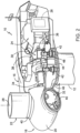
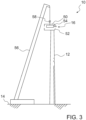
- FIG. 1 illustrates a perspective view of a wind turbine 10.
- the wind turbine 10 generally includes a tower 12 extending from a support surface 14, a nacelle 16 mounted on the tower 12, and a rotor 18 coupled to the nacelle 16.
- the nacelle 16 corresponds to the overall housing structure and has a bottom wall, opposing side walls, a front wall, a rear wall, and a top wall.
- the front wall may have a main shaft opening configured to receive a main shaft 34 ( FIG. 2 ) there through that is connectable to the rotor 18.
- the rotor 18 includes a rotatable hub 20 and at least one rotor blade 22 coupled to and extending outwardly from the hub 20.
- the rotor 18 includes three rotor blades 22.
- the rotor 18 may include more or less than three rotor blades 22.
- Each rotor blade 22 may be spaced about the hub 20 to facilitate rotating the rotor 18 to enable kinetic energy to be transferred from the wind into usable mechanical energy, and subsequently, electrical energy.
- the hub 20 may be rotatably coupled to an electric generator 24 ( FIG. 2 ) positioned within the nacelle 16 to permit electrical energy to be produced.
- the wind turbine 10 may also include a wind turbine controller 26 centralized within the nacelle 16. However, in other wind turbines, the controller 26 may be located within any other component of the wind turbine 10 or at a location outside the wind turbine 10. Further, the controller 26 may be communicatively coupled to any number of the components of the wind turbine 10 in order to control the components. As such, the controller 26 may include a computer or other suitable processing unit. Thus, in several wind turbines, the controller 26 may include suitable computer-readable instructions that, when implemented, configure the controller 26 to perform various different functions, such as receiving, transmitting and/or executing wind turbine control signals.
- FIG. 2 a simplified, internal view of an exemplary nacelle 16 of the wind turbine 10 shown in FIG. 1 , particularly illustrating the drivetrain components thereof, is illustrated.
- the generator 24 may be coupled to the rotor 18 for producing electrical power from the rotational energy generated by the rotor 18.
- the rotor 18 may be coupled to the main shaft 34, which is rotatable via a main bearing (not shown).
- the main shaft 34 may, in turn, be rotatably coupled to a gearbox output shaft 36 of the generator 24 through a gearbox 30.
- the gearbox 30 may include a gearbox housing 38 that is connected to the bedplate 46 by one or more torque arms 48.
- the bedplate 46 may be a forged component in which the main bearing (not shown) is seated and through which the main shaft 34 extends.
- the main shaft 34 provides a low speed, high torque input to the gearbox 30 in response to rotation of the rotor blades 22 and the hub 20.
- the gearbox 30 thus converts the low speed, high torque input to a high speed, low torque output to drive the gearbox output shaft 36 and, thus, the generator 24.
- Each rotor blade 22 may also include a pitch adjustment mechanism 32 configured to rotate each rotor blade 22 about its pitch axis 28 via a pitch bearing 40.
- the wind turbine 10 may include one or more yaw drive mechanisms 42 communicatively coupled to the controller 26, with each yaw drive mechanism(s)42 being configured to change the angle of the nacelle 16 relative to the wind (e.g., by engaging a yaw bearing 44 of the wind turbine 10).
- a nacelle and wind turbine components positioned within the nacelle, including the drivetrain can have a combined mass of more than 100 (metric) tonnes, particularly of more than 150 tonnes or 200 tonnes.
- the drivetrain of the wind turbine exceeds 100 (metric) tonnes, particularly of more than 150 tonnes or 200 tonnes.
- the wind turbine may be an onshore wind turbine. In several embodiments, the wind turbine may be an offshore wind turbine.
- FIGS. 3-7 show a wind turbine, or an assembling set of parts of a wind turbine during mounting of a nacelle, or during carrying at least one component and a roof of a nacelle, according to embodiments described herein.
- a component of a wind turbine and a roof of a nacelle of the wind may be connected to, for example, hooked to or fixed at, a lifting device, particularly to a crane, such as a mobile crane, an offshore crane, especially to a crane hook of a crane.
- a lifting device particularly to a crane, such as a mobile crane, an offshore crane, especially to a crane hook of a crane.
- the component and the roof may be lifted together using the lifting device.
- a roof 50 of a nacelle 16 and at least one component 54 of a wind turbine 10 are hooked to a crane hook 58 of a crane 56 and lifted using the crane 56.
- a component of a wind turbine can include a mechanical, electrical or electromechanical device, in particular associated with energy production or conversion.
- a component includes at least one of a drivetrain, a drivetrain component and a transformer.
- a drivetrain component may include a gearbox, a main shaft, a main bearing and/or a generator.
- a component can be heavier than 10 (metric) tonnes, in particular, heavier than 50 tonnes or heavier than 70 tonnes, and/or the component can be heavier than the roof.
- a roof of a nacelle can form at least a part of a top wall of the nacelle.
- the roof may include at least one of: at least a part of a side wall, at least a part of a front wall, at least a part of a rear wall and at least a part of a bottom wall of the nacelle.
- the roof can have a weight of more than 0.3 tonnes, in particular, more than 0.5 tonnes or 0.7 tonnes, and/or less than 3 tonnes, particularly less than 2.5 tonnes or 2 tonnes.
- Lifting a roof together with a component might reduce the sensitivity of the lifting process to wind loading as compared to lifting the roof alone. With some embodiments, it might be possible to have more favorable wind speed thresholds for lifting.
- a nacelle may include a base coupled to a tower of the wind turbine.
- the base can include a bedplate and/or at least a part of the bottom wall of the nacelle.
- the roof can be configured for mounting to a base of the nacelle, in particular using a releasable connecting device, e. g. by positive locking of the roof and the base or via a fastener such as a bolt.
- the crane 56 may be any crane with a sufficient lifting capacity to lift the component 54 and the roof 50 to the top of a tower 12 of the wind turbine 10.
- the crane 56 may be positioned on a support surface 14 near the tower 12 or may be coupled to the tower 12.
- FIG. 3 shows the roof 50 and the component 54 lifted above a tower 12 of the wind turbine 10 and above a base 52 of the nacelle 16.
- the crane hook includes a lifting tool of the crane, the lifting tool including a beam.
- the crane hook may further include a single hook as shown in FIGS. 3-6 .
- the lifting tool of the crane may further include e. g. one or more hooks or shackles and/or a device for stabilizing or balancing the crane hook.
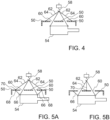
- FIG. 4 shows a component 54 and a roof 50 hooked to a crane hook 58.
- the component 54 is connected to the crane hook 58 using a first connecting device 62.
- the roof 50 includes an opening 60, which allows the first connecting device 62 to reach from the component 54 through the roof 50 to the crane hook 58.
- FIG. 4 shows an assembling set of parts of a wind turbine according to embodiments described herein in a hooked state.
- the roof can include at least two openings or at least three openings allowing, for example, a first connecting device to reach from the component through the roof to the crane hook.
- the openings may have a diameter of at least 10 cm, for example of at least 15 cm or of at least 20 cm.
- the opening might have a maximum diameter or maximum elongation of 100 cm or of 50 cm.
- the roof may be connected to the crane hook using a second connecting device.
- FIGS. 5A and 5B show a component 54 and a roof 50 hooked to a crane hook 58 in two exemplary configurations, wherein the roof 50 is connected to the component 54 using a third connecting device 66.
- the invention is not restricted to these two exemplary configurations.
- the first connecting device, the second connecting device and/or the third connecting device may include a sling, a rope and/or a chain.
- the roof can include a fastening site on the inside of the roof.
- the fastening site on the inside of the roof can be configured as a fixation device, for a third connecting device, for connecting the roof to the at least one component.
- the fastening site may include a loop, a hook and/or a shackle.
- the roof may include at least two fastening sites or at least three fastening sites on the inside of the roof.
- the third connecting device might help to stabilize the roof and/or the component, e.g. during occurrence of wind. In further embodiments, no third connecting device is used or necessary.
- the roof is not fixedly mounted to the component during lifting.
- the connecting devices are flexible and do not provide a fixed connection.
- the roof is fixedly connected with components, e.g. by screws or bolts.
- FIGS. 5A and 5B each show the roof 50 with a fastening site 68 on the inside of the roof 50, wherein the fastening site 68 is configured and is used as a fixation device for the third connecting device 66.
- the roof might include a further fastening site on the outside of the roof as a fixation device for the second connecting device.
- FIG. 5A shows the roof 50 with two further fastening sites 70 connected to the crane hook 58 using two second connecting devices 64
- FIG. 5B the roof 50 includes a single further fastening site 70 located centrally on the roof 50 and connected to the crane hook 58 using a single second connecting device 64.
- connecting devices including the first connecting device, the second connecting device and/or the third connecting device is not limited to the embodiments shown in FIGS. 4A and 4B.
- the number and configuration of connecting devices may be adapted depending on the loading capacity of the connecting devices or on the sensitivity of the roof to wind loading.
- more than one first connecting device may reach through one opening.
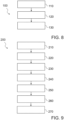
- FIG. 6A shows an exemplary embodiment with a component 54 and a roof 50 hooked to a crane hook 58 and lifted to the top of a tower 12 with a base 52 coupled to the tower 12.
- a hooked state as shown in FIG. 6A , the load of the component and of the roof can be carried by the crane hook 58.
- the component In the hooked state shown in FIG. 6A , the component may be positioned and fixed in the base 52. After fixing the component 54, the crane hook 58 and the roof 50 may be lowered, as illustrated in FIG. 6B . In FIG. 6B , the crane hook may carry only the load of the roof 50.
- the first connecting device 62 and the third connecting device 66 may be in a relaxed state or might be removed.
- the roof 50 may further be positioned and fixed on the base 52 of the nacelle 16. After positioning and fixing, the component 54 and the roof 50 may be in a mounted state and positioned at a mounting distance.
- a first length of a first connecting device and a second length of a second connecting device may be configured such that in a hooked state, particularly in a hooked state of an assembling set according to embodiments described herein, at least one component and a roof are hooked together on a crane hook at a hooking distance.
- the hooking distance can be at least 5 cm, particularly at least 10 cm or at least 15 cm, or at most 200 cm, or at most 100 cm, or at most 50 cm larger than a mounting distance between the at least one component and the roof in a mounted state, particularly of an assembling set, wherein in the mounted state the component and the roof are fixed to a base of a nacelle.
- a third length of a third connecting device may be configured such that, in a hooked state of at least one component and a roof with the component and the roof connected by the third connecting device, the component and the roof cannot swing or move relative to the other. Preventing the swinging of a component and a roof relative to the other in a hooked state might prevent the component and the roof from colliding or becoming damaged. For instance, swinging of a component and a roof relative to the other in a hooked state might occur due to different sensitivities of the roof and the component to wind loading.
- a component 54 in particular a transformer of a wind turbine 10
- a roof 50 are lifted for mounting to a base 52 of a nacelle 16, in particular to a rear side of the nacelle 16.
- a further component 72 of the wind turbine 10 may already be fixed to the base 52.
- the roof 50 may include a part of a rear wall of the nacelle 16 and/or a part of a bottom wall of the nacelle 16.
- FIG. 8 a flow diagram of a typical embodiment of a method 100 of mounting a nacelle of a wind turbine, such as the wind turbine 10 of FIG. 1 , and at least one component of the wind turbine on a tower of the wind turbine is illustrated.
- the method 100 includes hooking (block 110) a roof of the nacelle to a crane hook of a crane, and hooking (block 120) the at least one component to the crane hook of the crane.
- the method 100 further includes lifting (block 130) the roof of the nacelle together with the at least one component using the crane.
- the method 200 includes hooking (block 210) a roof of the nacelle to a crane hook of a crane, and hooking (block 220) a component to the crane hook of the crane.
- hooking a roof to a crane hook can include connecting the roof of the nacelle to the crane hook using a second connecting device, particularly by connecting the second connecting device to a further fastening site on the outside of the roof.
- hooking a component to a crane hook can include connecting the component to the crane hook using a first connecting device, wherein the first connecting device reaches through an opening in the roof of the nacelle.
- Hooking the component to the crane hook can include connecting the roof of the nacelle to the component using a third connecting device, particularly by connecting the third connecting device to a fastening site on the inside of the roof.
- hooking a component to a crane hook can include stabilizing the roof of the nacelle and the component at a hooking distance, wherein the hooking distance is at least 5 cm, in particular at least 10 cm or at least 15 cm, larger than a mounting distance between the roof and the component in the mounted nacelle.
- the roof can be stabilized above the component.
- hooking a component to a crane hook can include stabilizing the roof of the nacelle and the component at a hooking distance, wherein the hooking distance is maximum 150 cm, in particular maximum 50 cm or maximum 30 cm, larger than a mounting distance between the roof and the component in the mounted nacelle.
- "Mounted nacelle” might typically refer to a mounting status in which the nacelle and the wind turbine are ready for normal service.
- the method 200 includes lifting (block 230) the roof of the nacelle together with the component using the crane.
- the component and the roof may be in a hooked state, for example as described in conjunction with the exemplary embodiments shown in FIGS. 3 , 4, 5A, 5B , 6A or 7 .
- the roof and the component may be lifted from a support surface, e. g. from ground or from a ship, to a base of a nacelle on a tower of a wind turbine.
- the roof and the component may be lifted from a base to a support surface.
- the roof may be mounted non-fixedly to the component during at least one of hooking the roof to the crane hook, hooking the at least one component to the crane hook and lifting.
- the roof may be mounted non-fixedly to the component in a hooked state.
- Non-fixedly typically refers to a mounting, using flexible connecting devices such as ropes or slings.
- the method 200 can include positioning (block 240) and fixing the component in a base of the nacelle.
- the component may be lowered to its designated position in the base and may then be fixed to the base.
- the component and the roof may still be separated by the hooking distance or by a distance larger than the mounting distance.
- the method 200 may proceed with positioning (block 250) and fixing the roof on the base.
- the roof may be lowered onto the base, as described e. g. in conjunction with FIG. 6B , and may then be fixed to the base, in particular using a releasable connecting device.
- a releasable connecting device might allow a roof to be easily removed, for example to repair or to replace a component or a further component of a wind turbine.
- a releasable connecting device may include a device for positive locking of the roof and the base, or releasable fasteners such as bolts.
- the method 200 may include disconnecting (block 260) the component and the roof from the crane hook, in particular disconnecting the first connecting device from the component or from the crane hook and/or disconnecting the second connecting device from the roof or from the crane hook.
- the method 200 may include closing (block 270) the opening, particularly using a lid.
- the method can include hooking a roof of the nacelle to a crane hook of a crane and hooking the damaged component to the crane hook.
- the method may include lifting the roof together with the damaged component from a base of the nacelle on a tower of the wind turbine to a support surface.
- the method may proceed with further steps of embodiments of the method as described herein, in particular in conjunction with FIG. 8 or FIG 9 , wherein in the further steps the component may be the damaged component after repair or a replacement component.
- hooking the roof to the crane hook may be performed before hooking the component to the crane hook.
- hooking the roof to the crane hook may be performed after hooking the component to the crane hook.
- hooking the roof to the crane hook may be performed simultaneously with hooking the component to the crane hook.
- the order of mentioning the hooking of the roof and the component does not necessarily describe the order of the hooking in described exemplary embodiments.
- the roof and the component are placed under the crane hook, e.g. with spacers or in a mounting distance using a fixation device, before hooking them.
- the various embodiments of the method and the assembling set of parts of a wind turbine may advantageously reduce the number of lifting steps required for lifting a component of a wind turbine and a roof of a nacelle to and/or from a tower or base of the wind turbine, in particular to half the number of lifting steps.
- lifting the component and the roof together can decrease the sensitivity of lifting to wind loading as compared to lifting the roof alone.
- decreasing the sensitivity to wind loading can reduce the time and costs associated with lifting the component and the roof, since lifting is less dependent on wind conditions. Decreasing the sensitivity to wind loading can reduce the risk of damaging the roof during lifting.
Landscapes
- Engineering & Computer Science (AREA)
- Life Sciences & Earth Sciences (AREA)
- Sustainable Development (AREA)
- Sustainable Energy (AREA)
- Chemical & Material Sciences (AREA)
- Combustion & Propulsion (AREA)
- Mechanical Engineering (AREA)
- General Engineering & Computer Science (AREA)
- Wind Motors (AREA)
Claims (13)
- Verfahren (100, 200) zum Montieren einer Gondel einer Windturbine und mindestens einer Komponente der Windturbine auf einem Turm der Windturbine, wobei das Verfahren umfasst:- Einhaken (110, 210) eines Daches der Gondel an einem Kranhaken eines Krans, wobei der Kranhaken ein Hebewerkzeug des Krans umfasst, wobei das Hebewerkzeug einen Balken umfasst;- Einhaken (120, 220) der mindestens einen Komponente an den Kranhaken des Krans, wobei die mindestens eine Komponente einen Antriebsstrang, eine Antriebsstrangkomponente und/oder einen Transformator umfasst; und- Anheben (130, 230) des Dachs der Gondel zusammen mit der mindestens einen Komponente unter Verwendung des Krans;wobei das Einhängen (120, 220) der mindestens einen Komponente an den Kranhaken das Verbinden der mindestens einen Komponente mit dem Kranhaken unter Verwendung einer ersten Verbindungsvorrichtung umfasst, wobei die erste Verbindungsvorrichtung durch eine Öffnung im Dach der Gondel hindurchreicht;wobei das Einhängen (110, 210) des Dachs an den Kranhaken das Verbinden des Dachs mit dem Kranhaken unter Verwendung einer zweiten Verbindungsvorrichtung umfasst; undwobei die erste Verbindungsvorrichtung und die zweite Verbindungsvorrichtung flexible Verbindungsvorrichtungen sind.
- Verfahren (100, 200) nach Anspruch 1, wobei das Einhaken (120, 220) das Stabilisieren des Dachs der Gondel und der mindestens einen Komponente in einem Einhakabstand umfasst, wobei der Einhakabstand mindestens 5 cm größer ist als ein Montageabstand zwischen dem Dach und der mindestens einen Komponente in der montierten Gondel.
- Verfahren (100, 200) nach einem der Ansprüche 1 bis 2, wobei das Dach während des Einhakens (110, 210) des Dachs in den Kranhaken, des Einhakens (120, 220) der mindestens einen Komponente in den Kranhaken und/oder des Anhebens (130, 230) nicht fest an der Komponente angebracht ist.
- Verfahren (100, 200) nach einem der Ansprüche 1 bis 3, wobei das Einhaken (110, 210) ferner umfasst:- Verbinden des Daches der Gondel mit der mindestens einen Komponente unter Verwendung einer dritten Verbindungsvorrichtung.
- Verfahren (100, 200) nach einem der Ansprüche 1 bis 4, ferner umfassend:- Positionieren (240) und Befestigen der mindestens einen Komponente in einer Basis der Gondel; und- nach dem Befestigen der mindestens einen Komponente Positionieren (250) und Befestigen des Dachs auf der Basis der Gondel.
- Verfahren (100) nach einem der Ansprüche 1 bis 5, wobei die mindestens eine Komponente mindestens eines der folgenden Elemente oder Kombinationen davon umfasst: ein Getriebe, eine Hauptwelle, ein Hauptlager und einen Generator.
- Verfahren (100) nach einem der Ansprüche 1 bis 6, wobei die mindestens eine Komponente schwerer als 10 Tonnen ist und/oder wobei die mindestens eine Komponente schwerer als das Dach der Gondel ist.
- Verfahren (100) nach einem der Ansprüche 1 bis 7, wobei das Dach der Gondel eine Befestigungsstelle auf der Innenseite des Daches umfasst.
- Montageset von Teilen einer Windturbine (10), die an einem Kranhaken (58) eines Krans einzuhaken sind, wobei der Kranhaken ein Hebewerkzeug des Krans umfasst, wobei das Hebewerkzeug einen Balken umfasst, wobei das Montageset umfasst:- mindestens eine Komponente (54) der Windturbine (10), wobei die mindestens eine Komponente (54) einen Antriebsstrang, eine Antriebsstrangkomponente und/oder einen Transformator umfasst;- ein Dach (50) einer Gondel (16) der Windturbine (10), wobei das Dach (50) eine Öffnung (60) umfasst;- eine erste Verbindungsvorrichtung (62) zum Verbinden der mindestens einen Komponente (54) mit dem Kranhaken (58); und- eine zweite Verbindungsvorrichtung (64) zum Verbinden des Dachs (50) mit dem Kranhaken (58);- wobei die Öffnung (60) in dem Dach (50) so positioniert ist, dass die erste Verbindungsvorrichtung (62) von der mindestens einen Komponente (54) durch das Dach (50) hindurch zu dem Kranhaken (58) reichen kann; und- wobei die erste Verbindungsvorrichtung (62) und die zweite Verbindungsvorrichtung (64) flexible Verbindungsvorrichtungen sind.
- Montageset nach Anspruch 9, wobei eine erste Länge der ersten Verbindungseinrichtung (62) und eine zweite Länge der zweiten Verbindungseinrichtung (64) so konfiguriert sind, dass in einem eingehakten Zustand des Montagesets die mindestens eine Komponente (54) und das Dach (50) an dem Kranhaken (58) in einem Einhakabstand eingehakt sind, wobei der Einhakabstand mindestens 5 cm größer ist als ein Montageabstand zwischen der mindestens einen Komponente (54) und dem Dach (50) in einem montierten Zustand des Montagesets, wobei in dem montierten Zustand die mindestens eine Komponente (54) und das Dach (50) an einer Basis (52) der Gondel (16) befestigt sind.
- Montageset nach einem der Ansprüche 9 bis 10, wobei das Dach (50) der Gondel (16) zur Montage an einer Basis (52) der Gondel (16) über eine lösbare Verbindungsvorrichtung konfiguriert ist.
- Montageset nach einem der Ansprüche 9 bis 11, umfassend eine dritte Verbindungsvorrichtung (66) zum Verbinden des Daches (50) mit der mindestens einen Komponente (54), wobei das Dach (50) eine Befestigungsstelle (68) auf der Innenseite des Daches (50) als Fixiervorrichtung für die dritte Verbindungsvorrichtung (66) umfasst.
- Montageset nach einem der Ansprüche 9 bis 12, wobei die mindestens eine Komponente (54) schwerer als 10 Tonnen ist und/oder wobei die mindestens eine Komponente (54) schwerer als das Dach (50) der Gondel (16) ist.
Priority Applications (4)
| Application Number | Priority Date | Filing Date | Title |
|---|---|---|---|
| ES19194433T ES3036085T3 (en) | 2019-08-29 | 2019-08-29 | Method of mounting a nacelle of a wind turbine and assembling set of parts of a wind turbine |
| DK19194433.9T DK3786448T3 (da) | 2019-08-29 | 2019-08-29 | Fremgangsmåde til montering af en vindmølles nacelle og samlesæt af dele af en vindmølle |
| EP19194433.9A EP3786448B1 (de) | 2019-08-29 | 2019-08-29 | Verfahren zur montage einer gondel einer windturbine und montagesatz von teilen einer windturbine |
| US17/004,100 US11353007B2 (en) | 2019-08-29 | 2020-08-27 | Method of mounting a nacelle of a wind turbine and assembling set of parts of a wind turbine |
Applications Claiming Priority (1)
| Application Number | Priority Date | Filing Date | Title |
|---|---|---|---|
| EP19194433.9A EP3786448B1 (de) | 2019-08-29 | 2019-08-29 | Verfahren zur montage einer gondel einer windturbine und montagesatz von teilen einer windturbine |
Publications (2)
| Publication Number | Publication Date |
|---|---|
| EP3786448A1 EP3786448A1 (de) | 2021-03-03 |
| EP3786448B1 true EP3786448B1 (de) | 2025-04-23 |
Family
ID=67809364
Family Applications (1)
| Application Number | Title | Priority Date | Filing Date |
|---|---|---|---|
| EP19194433.9A Active EP3786448B1 (de) | 2019-08-29 | 2019-08-29 | Verfahren zur montage einer gondel einer windturbine und montagesatz von teilen einer windturbine |
Country Status (4)
| Country | Link |
|---|---|
| US (1) | US11353007B2 (de) |
| EP (1) | EP3786448B1 (de) |
| DK (1) | DK3786448T3 (de) |
| ES (1) | ES3036085T3 (de) |
Families Citing this family (2)
| Publication number | Priority date | Publication date | Assignee | Title |
|---|---|---|---|---|
| CN114945748B (zh) * | 2019-11-22 | 2025-06-20 | 维斯塔斯风力系统有限公司 | 用于风力涡轮机的机舱 |
| CN114945751B (zh) * | 2019-12-19 | 2025-07-22 | 维斯塔斯风力系统有限公司 | 用于安装或移除风力涡轮机部件的方法 |
Citations (3)
| Publication number | Priority date | Publication date | Assignee | Title |
|---|---|---|---|---|
| CN105540410A (zh) * | 2015-12-29 | 2016-05-04 | 江苏金风科技有限公司 | 风力发电机组的吊装设备和吊装方法 |
| CN108190725A (zh) * | 2017-12-30 | 2018-06-22 | 北京金风科创风电设备有限公司 | 吊装装置以及机舱吊装方法 |
| EP3404259A1 (de) * | 2017-05-18 | 2018-11-21 | Senvion GmbH | Verfahren, lastaufnahmemittel und montagesystem zum zusammenbauen einer windenergieanlage |
Family Cites Families (15)
| Publication number | Priority date | Publication date | Assignee | Title |
|---|---|---|---|---|
| DE102007012848B4 (de) * | 2007-03-17 | 2013-09-19 | Aerodyn Engineering Gmbh | Verfahren zum Reparieren einer Offshore-Windenergieanlage und Wasserfahrzeug zur Durchführung des Verfahrens |
| DK176966B1 (da) * | 2008-07-14 | 2010-08-02 | Vestas Wind Sys As | Fremgangsmåde til rejsning af en vindmølle på et offshore-sted og et fartøj til rejsning af en vindmølle på et offshore-sted |
| CN101778757B (zh) * | 2008-08-28 | 2013-06-12 | 三菱重工业株式会社 | 海上风力发电装置的建设方法及建设装置 |
| US20100232977A1 (en) * | 2009-03-13 | 2010-09-16 | Vestas Wind Systems A/S | Height Adjustable Wind Turbine Nacelle |
| WO2010102635A2 (en) * | 2009-03-13 | 2010-09-16 | Vestas Wind Systems A/S | Wind turbine nacelle |
| US20130180444A1 (en) * | 2010-09-24 | 2013-07-18 | Technip France | Offshore wind turbine installation vessel |
| US9677543B2 (en) * | 2010-11-01 | 2017-06-13 | Mitsubishi Heavy Industries, Ltd. | Structure for nacelle cover connection portion of wind turbine generator |
| CA2775641C (en) * | 2011-05-02 | 2014-07-08 | Hallin Marine Singapore Pte Ltd | Apparatus and methods of positioning a subsea object |
| US20160369778A1 (en) * | 2011-05-11 | 2016-12-22 | Daniel E. Davis | Method of assembling a wind turbine |
| US9261072B2 (en) * | 2011-05-11 | 2016-02-16 | Daniel E. Davis | Wind turbine elevator for hoisting a naecelle along a tower and pivoting the naecelle at a top of the tower |
| DK178538B1 (en) * | 2013-04-24 | 2016-06-06 | Envision Energy Denmark Aps | Method for assembling and transporting an offshore wind turbine |
| EP3070044B1 (de) * | 2015-03-19 | 2018-08-08 | ALSTOM Renewable Technologies | Hebesysteme und -verfahren |
| DK3242014T3 (da) * | 2016-05-02 | 2019-12-02 | Nordex Energy Gmbh | Nacellebeklædning til et vindenergianlæg |
| DE102017004291A1 (de) * | 2017-05-04 | 2018-11-08 | Senvion Gmbh | Einhausung für eine Gondel einer Windenergieanlage |
| DE102017004800A1 (de) * | 2017-05-18 | 2018-11-22 | Senvion Gmbh | Gondelkomponente für eine Windenergieanlage und Verfahren zum Montieren einer Gondelkomponente |
-
2019
- 2019-08-29 DK DK19194433.9T patent/DK3786448T3/da active
- 2019-08-29 ES ES19194433T patent/ES3036085T3/es active Active
- 2019-08-29 EP EP19194433.9A patent/EP3786448B1/de active Active
-
2020
- 2020-08-27 US US17/004,100 patent/US11353007B2/en active Active
Patent Citations (3)
| Publication number | Priority date | Publication date | Assignee | Title |
|---|---|---|---|---|
| CN105540410A (zh) * | 2015-12-29 | 2016-05-04 | 江苏金风科技有限公司 | 风力发电机组的吊装设备和吊装方法 |
| EP3404259A1 (de) * | 2017-05-18 | 2018-11-21 | Senvion GmbH | Verfahren, lastaufnahmemittel und montagesystem zum zusammenbauen einer windenergieanlage |
| CN108190725A (zh) * | 2017-12-30 | 2018-06-22 | 北京金风科创风电设备有限公司 | 吊装装置以及机舱吊装方法 |
Also Published As
| Publication number | Publication date |
|---|---|
| DK3786448T3 (da) | 2025-06-30 |
| EP3786448A1 (de) | 2021-03-03 |
| US20210062791A1 (en) | 2021-03-04 |
| US11353007B2 (en) | 2022-06-07 |
| ES3036085T3 (en) | 2025-09-12 |
Similar Documents
| Publication | Publication Date | Title |
|---|---|---|
| EP2344753B1 (de) | Wartungskran für eine windturbine | |
| US9476403B2 (en) | Wind turbine blade lowering apparatus | |
| EP3431751B1 (de) | System und verfahren zur uptower-aufhängung einer rotorschaufel einer windturbine | |
| US20100005656A1 (en) | A method for fitting the rotor of a wind generator | |
| US11353007B2 (en) | Method of mounting a nacelle of a wind turbine and assembling set of parts of a wind turbine | |
| US11965479B2 (en) | System and method for repairing a gearbox of a wind turbine uptower | |
| US10641042B2 (en) | External ladder assembly for wind turbine nacelle | |
| US10801473B2 (en) | Hub crane assembly for a wind turbine | |
| EP4019770A1 (de) | Schaufelhebevorrichtung zur montage einer schaufel an einer rotornabe einer windturbine oder zur demontage einer schaufel von einer rotornabe einer windturbine | |
| US20160305532A1 (en) | Gearbox adjustment system | |
| US10570888B2 (en) | Working platform within a nacelle of a wind turbine | |
| EP4027007B1 (de) | Verfahren zur montage von schaufeln an einer rotornabe einer windturbine | |
| US12123392B2 (en) | Method of assembling or disassembling a rotor blade of a wind turbine | |
| US12281636B2 (en) | Method of servicing or installing a component of a wind turbine using a crane | |
| EP4414555B1 (de) | Kupplungen und hilfskomponenten für windturbinen und zugehörige verfahren | |
| EP4224009A1 (de) | Schaufelsegment für eine rotorschaufel einer windturbine | |
| EP3364023B1 (de) | System und verfahren zum entfernen oder installieren einer hauptwelle einer windturbine |
Legal Events
| Date | Code | Title | Description |
|---|---|---|---|
| PUAI | Public reference made under article 153(3) epc to a published international application that has entered the european phase |
Free format text: ORIGINAL CODE: 0009012 |
|
| STAA | Information on the status of an ep patent application or granted ep patent |
Free format text: STATUS: THE APPLICATION HAS BEEN PUBLISHED |
|
| AK | Designated contracting states |
Kind code of ref document: A1 Designated state(s): AL AT BE BG CH CY CZ DE DK EE ES FI FR GB GR HR HU IE IS IT LI LT LU LV MC MK MT NL NO PL PT RO RS SE SI SK SM TR |
|
| AX | Request for extension of the european patent |
Extension state: BA ME |
|
| STAA | Information on the status of an ep patent application or granted ep patent |
Free format text: STATUS: REQUEST FOR EXAMINATION WAS MADE |
|
| 17P | Request for examination filed |
Effective date: 20210813 |
|
| RBV | Designated contracting states (corrected) |
Designated state(s): AL AT BE BG CH CY CZ DE DK EE ES FI FR GB GR HR HU IE IS IT LI LT LU LV MC MK MT NL NO PL PT RO RS SE SI SK SM TR |
|
| STAA | Information on the status of an ep patent application or granted ep patent |
Free format text: STATUS: EXAMINATION IS IN PROGRESS |
|
| 17Q | First examination report despatched |
Effective date: 20230215 |
|
| P01 | Opt-out of the competence of the unified patent court (upc) registered |
Effective date: 20230530 |
|
| RAP1 | Party data changed (applicant data changed or rights of an application transferred) |
Owner name: GENERAL ELECTRIC RENOVABLES ESPANA, S.L. |
|
| GRAP | Despatch of communication of intention to grant a patent |
Free format text: ORIGINAL CODE: EPIDOSNIGR1 |
|
| STAA | Information on the status of an ep patent application or granted ep patent |
Free format text: STATUS: GRANT OF PATENT IS INTENDED |
|
| GRAJ | Information related to disapproval of communication of intention to grant by the applicant or resumption of examination proceedings by the epo deleted |
Free format text: ORIGINAL CODE: EPIDOSDIGR1 |
|
| GRAP | Despatch of communication of intention to grant a patent |
Free format text: ORIGINAL CODE: EPIDOSNIGR1 |
|
| GRAJ | Information related to disapproval of communication of intention to grant by the applicant or resumption of examination proceedings by the epo deleted |
Free format text: ORIGINAL CODE: EPIDOSDIGR1 |
|
| STAA | Information on the status of an ep patent application or granted ep patent |
Free format text: STATUS: EXAMINATION IS IN PROGRESS |
|
| GRAP | Despatch of communication of intention to grant a patent |
Free format text: ORIGINAL CODE: EPIDOSNIGR1 |
|
| STAA | Information on the status of an ep patent application or granted ep patent |
Free format text: STATUS: GRANT OF PATENT IS INTENDED |
|
| INTG | Intention to grant announced |
Effective date: 20241008 |
|
| GRAJ | Information related to disapproval of communication of intention to grant by the applicant or resumption of examination proceedings by the epo deleted |
Free format text: ORIGINAL CODE: EPIDOSDIGR1 |
|
| STAA | Information on the status of an ep patent application or granted ep patent |
Free format text: STATUS: EXAMINATION IS IN PROGRESS |
|
| INTG | Intention to grant announced |
Effective date: 20241015 |
|
| INTG | Intention to grant announced |
Effective date: 20241022 |
|
| INTG | Intention to grant announced |
Effective date: 20241028 |
|
| INTG | Intention to grant announced |
Effective date: 20241105 |
|
| INTC | Intention to grant announced (deleted) | ||
| GRAP | Despatch of communication of intention to grant a patent |
Free format text: ORIGINAL CODE: EPIDOSNIGR1 |
|
| STAA | Information on the status of an ep patent application or granted ep patent |
Free format text: STATUS: GRANT OF PATENT IS INTENDED |
|
| INTG | Intention to grant announced |
Effective date: 20241217 |
|
| GRAS | Grant fee paid |
Free format text: ORIGINAL CODE: EPIDOSNIGR3 |
|
| GRAA | (expected) grant |
Free format text: ORIGINAL CODE: 0009210 |
|
| STAA | Information on the status of an ep patent application or granted ep patent |
Free format text: STATUS: THE PATENT HAS BEEN GRANTED |
|
| AK | Designated contracting states |
Kind code of ref document: B1 Designated state(s): AL AT BE BG CH CY CZ DE DK EE ES FI FR GB GR HR HU IE IS IT LI LT LU LV MC MK MT NL NO PL PT RO RS SE SI SK SM TR |
|
| REG | Reference to a national code |
Ref country code: GB Ref legal event code: FG4D |
|
| REG | Reference to a national code |
Ref country code: CH Ref legal event code: EP |
|
| REG | Reference to a national code |
Ref country code: DE Ref legal event code: R096 Ref document number: 602019068932 Country of ref document: DE |
|
| REG | Reference to a national code |
Ref country code: IE Ref legal event code: FG4D |
|
| REG | Reference to a national code |
Ref country code: DK Ref legal event code: T3 Effective date: 20250625 |
|
| REG | Reference to a national code |
Ref country code: NL Ref legal event code: MP Effective date: 20250423 |
|
| REG | Reference to a national code |
Ref country code: ES Ref legal event code: FG2A Ref document number: 3036085 Country of ref document: ES Kind code of ref document: T3 Effective date: 20250912 |
|
| PG25 | Lapsed in a contracting state [announced via postgrant information from national office to epo] |
Ref country code: NL Free format text: LAPSE BECAUSE OF FAILURE TO SUBMIT A TRANSLATION OF THE DESCRIPTION OR TO PAY THE FEE WITHIN THE PRESCRIBED TIME-LIMIT Effective date: 20250423 |
|
| REG | Reference to a national code |
Ref country code: AT Ref legal event code: MK05 Ref document number: 1787973 Country of ref document: AT Kind code of ref document: T Effective date: 20250423 |
|
| PG25 | Lapsed in a contracting state [announced via postgrant information from national office to epo] |
Ref country code: PT Free format text: LAPSE BECAUSE OF FAILURE TO SUBMIT A TRANSLATION OF THE DESCRIPTION OR TO PAY THE FEE WITHIN THE PRESCRIBED TIME-LIMIT Effective date: 20250825 Ref country code: FI Free format text: LAPSE BECAUSE OF FAILURE TO SUBMIT A TRANSLATION OF THE DESCRIPTION OR TO PAY THE FEE WITHIN THE PRESCRIBED TIME-LIMIT Effective date: 20250423 |
|
| PGFP | Annual fee paid to national office [announced via postgrant information from national office to epo] |
Ref country code: ES Payment date: 20250901 Year of fee payment: 7 |
|
| PGFP | Annual fee paid to national office [announced via postgrant information from national office to epo] |
Ref country code: DE Payment date: 20250724 Year of fee payment: 7 Ref country code: DK Payment date: 20250723 Year of fee payment: 7 |
|
| REG | Reference to a national code |
Ref country code: LT Ref legal event code: MG9D |
|
| PG25 | Lapsed in a contracting state [announced via postgrant information from national office to epo] |
Ref country code: GR Free format text: LAPSE BECAUSE OF FAILURE TO SUBMIT A TRANSLATION OF THE DESCRIPTION OR TO PAY THE FEE WITHIN THE PRESCRIBED TIME-LIMIT Effective date: 20250724 Ref country code: NO Free format text: LAPSE BECAUSE OF FAILURE TO SUBMIT A TRANSLATION OF THE DESCRIPTION OR TO PAY THE FEE WITHIN THE PRESCRIBED TIME-LIMIT Effective date: 20250723 |
|
| PG25 | Lapsed in a contracting state [announced via postgrant information from national office to epo] |
Ref country code: PL Free format text: LAPSE BECAUSE OF FAILURE TO SUBMIT A TRANSLATION OF THE DESCRIPTION OR TO PAY THE FEE WITHIN THE PRESCRIBED TIME-LIMIT Effective date: 20250423 |
|
| PG25 | Lapsed in a contracting state [announced via postgrant information from national office to epo] |
Ref country code: BG Free format text: LAPSE BECAUSE OF FAILURE TO SUBMIT A TRANSLATION OF THE DESCRIPTION OR TO PAY THE FEE WITHIN THE PRESCRIBED TIME-LIMIT Effective date: 20250423 |
|
| PG25 | Lapsed in a contracting state [announced via postgrant information from national office to epo] |
Ref country code: HR Free format text: LAPSE BECAUSE OF FAILURE TO SUBMIT A TRANSLATION OF THE DESCRIPTION OR TO PAY THE FEE WITHIN THE PRESCRIBED TIME-LIMIT Effective date: 20250423 |
|
| PG25 | Lapsed in a contracting state [announced via postgrant information from national office to epo] |
Ref country code: AT Free format text: LAPSE BECAUSE OF FAILURE TO SUBMIT A TRANSLATION OF THE DESCRIPTION OR TO PAY THE FEE WITHIN THE PRESCRIBED TIME-LIMIT Effective date: 20250423 |
|
| PG25 | Lapsed in a contracting state [announced via postgrant information from national office to epo] |
Ref country code: RS Free format text: LAPSE BECAUSE OF FAILURE TO SUBMIT A TRANSLATION OF THE DESCRIPTION OR TO PAY THE FEE WITHIN THE PRESCRIBED TIME-LIMIT Effective date: 20250723 |
|
| PG25 | Lapsed in a contracting state [announced via postgrant information from national office to epo] |
Ref country code: IS Free format text: LAPSE BECAUSE OF FAILURE TO SUBMIT A TRANSLATION OF THE DESCRIPTION OR TO PAY THE FEE WITHIN THE PRESCRIBED TIME-LIMIT Effective date: 20250823 |
|
| PG25 | Lapsed in a contracting state [announced via postgrant information from national office to epo] |
Ref country code: LV Free format text: LAPSE BECAUSE OF FAILURE TO SUBMIT A TRANSLATION OF THE DESCRIPTION OR TO PAY THE FEE WITHIN THE PRESCRIBED TIME-LIMIT Effective date: 20250423 |
|
| PG25 | Lapsed in a contracting state [announced via postgrant information from national office to epo] |
Ref country code: SM Free format text: LAPSE BECAUSE OF FAILURE TO SUBMIT A TRANSLATION OF THE DESCRIPTION OR TO PAY THE FEE WITHIN THE PRESCRIBED TIME-LIMIT Effective date: 20250423 |
|
| PG25 | Lapsed in a contracting state [announced via postgrant information from national office to epo] |
Ref country code: CZ Free format text: LAPSE BECAUSE OF FAILURE TO SUBMIT A TRANSLATION OF THE DESCRIPTION OR TO PAY THE FEE WITHIN THE PRESCRIBED TIME-LIMIT Effective date: 20250423 |
|
| PG25 | Lapsed in a contracting state [announced via postgrant information from national office to epo] |
Ref country code: EE Free format text: LAPSE BECAUSE OF FAILURE TO SUBMIT A TRANSLATION OF THE DESCRIPTION OR TO PAY THE FEE WITHIN THE PRESCRIBED TIME-LIMIT Effective date: 20250423 |
|
| REG | Reference to a national code |
Ref country code: DE Ref legal event code: R097 Ref document number: 602019068932 Country of ref document: DE |
|
| PG25 | Lapsed in a contracting state [announced via postgrant information from national office to epo] |
Ref country code: SK Free format text: LAPSE BECAUSE OF FAILURE TO SUBMIT A TRANSLATION OF THE DESCRIPTION OR TO PAY THE FEE WITHIN THE PRESCRIBED TIME-LIMIT Effective date: 20250423 Ref country code: RO Free format text: LAPSE BECAUSE OF FAILURE TO SUBMIT A TRANSLATION OF THE DESCRIPTION OR TO PAY THE FEE WITHIN THE PRESCRIBED TIME-LIMIT Effective date: 20250423 |
|
| PG25 | Lapsed in a contracting state [announced via postgrant information from national office to epo] |
Ref country code: IT Free format text: LAPSE BECAUSE OF FAILURE TO SUBMIT A TRANSLATION OF THE DESCRIPTION OR TO PAY THE FEE WITHIN THE PRESCRIBED TIME-LIMIT Effective date: 20250423 |
|
| PLBE | No opposition filed within time limit |
Free format text: ORIGINAL CODE: 0009261 |
|
| STAA | Information on the status of an ep patent application or granted ep patent |
Free format text: STATUS: NO OPPOSITION FILED WITHIN TIME LIMIT |
|
| REG | Reference to a national code |
Ref country code: CH Ref legal event code: L10 Free format text: ST27 STATUS EVENT CODE: U-0-0-L10-L00 (AS PROVIDED BY THE NATIONAL OFFICE) Effective date: 20260304 |
|
| REG | Reference to a national code |
Ref country code: CH Ref legal event code: H13 Free format text: ST27 STATUS EVENT CODE: U-0-0-H10-H13 (AS PROVIDED BY THE NATIONAL OFFICE) Effective date: 20260324 |