EP3786444B1 - Wind turbine blade apparatus - Google Patents
Wind turbine blade apparatus Download PDFInfo
- Publication number
- EP3786444B1 EP3786444B1 EP20155713.9A EP20155713A EP3786444B1 EP 3786444 B1 EP3786444 B1 EP 3786444B1 EP 20155713 A EP20155713 A EP 20155713A EP 3786444 B1 EP3786444 B1 EP 3786444B1
- Authority
- EP
- European Patent Office
- Prior art keywords
- wind turbine
- turbine blade
- side wall
- blade body
- wall surface
- Prior art date
- Legal status (The legal status is an assumption and is not a legal conclusion. Google has not performed a legal analysis and makes no representation as to the accuracy of the status listed.)
- Active
Links
- 239000000463 material Substances 0.000 claims description 9
- 238000010586 diagram Methods 0.000 description 7
- 230000001154 acute effect Effects 0.000 description 5
- 230000000694 effects Effects 0.000 description 4
- 238000000034 method Methods 0.000 description 4
- 230000006866 deterioration Effects 0.000 description 3
- 229920002943 EPDM rubber Polymers 0.000 description 2
- 239000004606 Fillers/Extenders Substances 0.000 description 2
- JOYRKODLDBILNP-UHFFFAOYSA-N Ethyl urethane Chemical compound CCOC(N)=O JOYRKODLDBILNP-UHFFFAOYSA-N 0.000 description 1
- 230000002542 deteriorative effect Effects 0.000 description 1
- 229920001971 elastomer Polymers 0.000 description 1
- 238000009434 installation Methods 0.000 description 1
- 238000010248 power generation Methods 0.000 description 1
- 238000000926 separation method Methods 0.000 description 1
- XLYOFNOQVPJJNP-UHFFFAOYSA-N water Substances O XLYOFNOQVPJJNP-UHFFFAOYSA-N 0.000 description 1
Images


Classifications
-
- F—MECHANICAL ENGINEERING; LIGHTING; HEATING; WEAPONS; BLASTING
- F03—MACHINES OR ENGINES FOR LIQUIDS; WIND, SPRING, OR WEIGHT MOTORS; PRODUCING MECHANICAL POWER OR A REACTIVE PROPULSIVE THRUST, NOT OTHERWISE PROVIDED FOR
- F03D—WIND MOTORS
- F03D1/00—Wind motors with rotation axis substantially parallel to the air flow entering the rotor
- F03D1/06—Rotors
- F03D1/0608—Rotors characterised by their aerodynamic shape
- F03D1/0633—Rotors characterised by their aerodynamic shape of the blades
- F03D1/0641—Rotors characterised by their aerodynamic shape of the blades of the section profile of the blades, i.e. aerofoil profile
-
- F—MECHANICAL ENGINEERING; LIGHTING; HEATING; WEAPONS; BLASTING
- F03—MACHINES OR ENGINES FOR LIQUIDS; WIND, SPRING, OR WEIGHT MOTORS; PRODUCING MECHANICAL POWER OR A REACTIVE PROPULSIVE THRUST, NOT OTHERWISE PROVIDED FOR
- F03D—WIND MOTORS
- F03D1/00—Wind motors with rotation axis substantially parallel to the air flow entering the rotor
- F03D1/06—Rotors
- F03D1/0608—Rotors characterised by their aerodynamic shape
- F03D1/0633—Rotors characterised by their aerodynamic shape of the blades
- F03D1/0645—Rotors characterised by their aerodynamic shape of the blades of the trailing edge region
-
- F—MECHANICAL ENGINEERING; LIGHTING; HEATING; WEAPONS; BLASTING
- F03—MACHINES OR ENGINES FOR LIQUIDS; WIND, SPRING, OR WEIGHT MOTORS; PRODUCING MECHANICAL POWER OR A REACTIVE PROPULSIVE THRUST, NOT OTHERWISE PROVIDED FOR
- F03D—WIND MOTORS
- F03D1/00—Wind motors with rotation axis substantially parallel to the air flow entering the rotor
- F03D1/06—Rotors
- F03D1/0608—Rotors characterised by their aerodynamic shape
- F03D1/0633—Rotors characterised by their aerodynamic shape of the blades
- F03D1/06495—Aerodynamic elements attached to or formed with the blade, e.g. flaps, vortex generators or noise reducers
-
- F—MECHANICAL ENGINEERING; LIGHTING; HEATING; WEAPONS; BLASTING
- F03—MACHINES OR ENGINES FOR LIQUIDS; WIND, SPRING, OR WEIGHT MOTORS; PRODUCING MECHANICAL POWER OR A REACTIVE PROPULSIVE THRUST, NOT OTHERWISE PROVIDED FOR
- F03D—WIND MOTORS
- F03D1/00—Wind motors with rotation axis substantially parallel to the air flow entering the rotor
- F03D1/06—Rotors
- F03D1/065—Rotors characterised by their construction elements
- F03D1/0675—Rotors characterised by their construction elements of the blades
- F03D1/069—Rotors characterised by their construction elements of the blades of the trailing edge region
-
- F—MECHANICAL ENGINEERING; LIGHTING; HEATING; WEAPONS; BLASTING
- F05—INDEXING SCHEMES RELATING TO ENGINES OR PUMPS IN VARIOUS SUBCLASSES OF CLASSES F01-F04
- F05B—INDEXING SCHEME RELATING TO WIND, SPRING, WEIGHT, INERTIA OR LIKE MOTORS, TO MACHINES OR ENGINES FOR LIQUIDS COVERED BY SUBCLASSES F03B, F03D AND F03G
- F05B2240/00—Components
- F05B2240/20—Rotors
- F05B2240/30—Characteristics of rotor blades, i.e. of any element transforming dynamic fluid energy to or from rotational energy and being attached to a rotor
- F05B2240/301—Cross-section characteristics
-
- F—MECHANICAL ENGINEERING; LIGHTING; HEATING; WEAPONS; BLASTING
- F05—INDEXING SCHEMES RELATING TO ENGINES OR PUMPS IN VARIOUS SUBCLASSES OF CLASSES F01-F04
- F05B—INDEXING SCHEME RELATING TO WIND, SPRING, WEIGHT, INERTIA OR LIKE MOTORS, TO MACHINES OR ENGINES FOR LIQUIDS COVERED BY SUBCLASSES F03B, F03D AND F03G
- F05B2240/00—Components
- F05B2240/20—Rotors
- F05B2240/30—Characteristics of rotor blades, i.e. of any element transforming dynamic fluid energy to or from rotational energy and being attached to a rotor
- F05B2240/304—Details of the trailing edge
- F05B2240/3042—Serrated trailing edge
-
- F—MECHANICAL ENGINEERING; LIGHTING; HEATING; WEAPONS; BLASTING
- F05—INDEXING SCHEMES RELATING TO ENGINES OR PUMPS IN VARIOUS SUBCLASSES OF CLASSES F01-F04
- F05B—INDEXING SCHEME RELATING TO WIND, SPRING, WEIGHT, INERTIA OR LIKE MOTORS, TO MACHINES OR ENGINES FOR LIQUIDS COVERED BY SUBCLASSES F03B, F03D AND F03G
- F05B2240/00—Components
- F05B2240/20—Rotors
- F05B2240/30—Characteristics of rotor blades, i.e. of any element transforming dynamic fluid energy to or from rotational energy and being attached to a rotor
- F05B2240/31—Characteristics of rotor blades, i.e. of any element transforming dynamic fluid energy to or from rotational energy and being attached to a rotor of changeable form or shape
- F05B2240/311—Characteristics of rotor blades, i.e. of any element transforming dynamic fluid energy to or from rotational energy and being attached to a rotor of changeable form or shape flexible or elastic
-
- F—MECHANICAL ENGINEERING; LIGHTING; HEATING; WEAPONS; BLASTING
- F05—INDEXING SCHEMES RELATING TO ENGINES OR PUMPS IN VARIOUS SUBCLASSES OF CLASSES F01-F04
- F05B—INDEXING SCHEME RELATING TO WIND, SPRING, WEIGHT, INERTIA OR LIKE MOTORS, TO MACHINES OR ENGINES FOR LIQUIDS COVERED BY SUBCLASSES F03B, F03D AND F03G
- F05B2250/00—Geometry
- F05B2250/10—Geometry two-dimensional
- F05B2250/18—Geometry two-dimensional patterned
- F05B2250/182—Geometry two-dimensional patterned crenellated, notched
-
- F—MECHANICAL ENGINEERING; LIGHTING; HEATING; WEAPONS; BLASTING
- F05—INDEXING SCHEMES RELATING TO ENGINES OR PUMPS IN VARIOUS SUBCLASSES OF CLASSES F01-F04
- F05B—INDEXING SCHEME RELATING TO WIND, SPRING, WEIGHT, INERTIA OR LIKE MOTORS, TO MACHINES OR ENGINES FOR LIQUIDS COVERED BY SUBCLASSES F03B, F03D AND F03G
- F05B2250/00—Geometry
- F05B2250/10—Geometry two-dimensional
- F05B2250/18—Geometry two-dimensional patterned
- F05B2250/183—Geometry two-dimensional patterned zigzag
-
- F—MECHANICAL ENGINEERING; LIGHTING; HEATING; WEAPONS; BLASTING
- F05—INDEXING SCHEMES RELATING TO ENGINES OR PUMPS IN VARIOUS SUBCLASSES OF CLASSES F01-F04
- F05B—INDEXING SCHEME RELATING TO WIND, SPRING, WEIGHT, INERTIA OR LIKE MOTORS, TO MACHINES OR ENGINES FOR LIQUIDS COVERED BY SUBCLASSES F03B, F03D AND F03G
- F05B2260/00—Function
- F05B2260/96—Preventing, counteracting or reducing vibration or noise
-
- Y—GENERAL TAGGING OF NEW TECHNOLOGICAL DEVELOPMENTS; GENERAL TAGGING OF CROSS-SECTIONAL TECHNOLOGIES SPANNING OVER SEVERAL SECTIONS OF THE IPC; TECHNICAL SUBJECTS COVERED BY FORMER USPC CROSS-REFERENCE ART COLLECTIONS [XRACs] AND DIGESTS
- Y02—TECHNOLOGIES OR APPLICATIONS FOR MITIGATION OR ADAPTATION AGAINST CLIMATE CHANGE
- Y02E—REDUCTION OF GREENHOUSE GAS [GHG] EMISSIONS, RELATED TO ENERGY GENERATION, TRANSMISSION OR DISTRIBUTION
- Y02E10/00—Energy generation through renewable energy sources
- Y02E10/70—Wind energy
- Y02E10/72—Wind turbines with rotation axis in wind direction
Definitions
- the present disclosure relates to a wind turbine blade apparatus.
- EP 2 921 697 A1 discloses a wind turbine blade with a trailing edge waveform profile which is formed - as seen from behind - by ruffles or alternating ridges and valleys formed on the airfoil and ending at the trailing edge.
- the first and second opposed surfaces defining the airfoil shape of the blade define a pressure side PS that has a concave surface and a suction side SS that has a convex surface. Further, the ridges are formed on the suction side SS and the valleys are formed on the pressure side PS.
- EP 2 028 366 A1 , EP 0 652 367 A1 and WO 2018/103803 A1 each disclose a wind turbine blade with a trailing edge portion that has - at least in some chord-directional cross sections - discontinuous points for which two different tangents can be set, i.e. which have essentially perpendicular flat surfaces facing towards the rear side.
- EP 2 667 019 A2 discloses an attachment member in the form of a trailing edge tape for a part of a trailing edge of a wind turbine rotor blade that allows to add a serration portion to the blade.
- the trailing edge tape is formed to mount a rearward protruding flat trailing edge extender with serrated traingles to the rear edge of the airfoil by means of a pair of flat installation flanges bifurcating from the flat trailing edge extender to be affixed on upper and lower surfaces of the airfoil.
- a flat serration portion may lead to deterioration of the aerodynamic performance of the wind turbine blade body, and tends to have an insufficient strength.
- a three-dimensional serration portion has an acute surface that does not continue to the blade surface at the deeply notched part of the valley portion. Thus, a flow passing through the acute surface generates alternate vortices, which may generate tonal sounds (noise close to pure tone).
- the present disclosure was made in view of the above, and an object of the present disclosure is to solve the noise problem of a wind turbine blade apparatus including a serration portion disposed on the wind turbine blade body, without deteriorating the aerodynamic performance.
- a wind turbine blade apparatus has the features of claim 1 including inter alia a wind turbine blade body, wherein a serration portion is disposed on at least a part of a trailing edge of the wind turbine blade body, the serration portion having a saw-teeth shape where a mountain portion and a valley portion are arranged alternately in a blade longitudinal direction, and wherein a chord-directional cross section of the wind turbine blade body along a chord direction is formed to have an airfoil shape at any position in a region from the mountain portion to the valley portion.
- the attachment member attached to at least a part of a trailing edge of a wind turbine blade body includes: a first-surface side wall surface disposed on a first surface of the wind turbine blade body; and a second-surface side wall surface disposed on a second surface of the wind turbine blade body, the second-surface side wall surface being connected to the first-surface side wall surface via a trailing edge portion, wherein trailing-edge portion sides of the first-surface side wall surface and the second-surface side wall surface are formed into a saw-teeth shape where a mountain portion and a valley portion are arranged alternately, and wherein a chord-directional cross section of the wind turbine blade body along a chord direction is formed to have an airfoil shape at any position in a region from the tip portion of the mountain portion to the deepest portion of the valley portion.
- the wind turbine blade apparatus With the wind turbine blade apparatus according to the present invention, it is possible to reduce broadband noise, while improving the lift-drag ratio (lift coefficient / drag coefficient) and maintaining a high aerodynamic performance. Furthermore, unlike the typical three-dimensional serration portion, it is possible to suppress occurrence of tonal sounds.
- an expression of relative or absolute arrangement such as “in a direction”, “along a direction”, “parallel”, “orthogonal”, “centered”, “concentric” and “coaxial” shall not be construed as indicating only the arrangement in a strict literal sense, but also includes a state where the arrangement is relatively displaced by a tolerance, or by an angle or a distance whereby it is possible to achieve the same function.
- an expression of an equal state such as “same” “equal” and “uniform” shall not be construed as indicating only the state in which the feature is strictly equal, but also includes a state in which there is a tolerance or a difference that can still achieve the same function.
- an expression of a shape such as a rectangular shape or a cylindrical shape shall not be construed as only the geometrically strict shape, but also includes a shape with unevenness or chamfered corners within the range in which the same effect can be achieved.
- FIG. 1 is a side view of a wind turbine power generating apparatus with a wind turbine blade apparatus according to an example serving to explain aspects of the invention.
- FIG. 2 is a perspective view of a wind turbine blade apparatus according to an example serving to explain aspects of the invention.
- a wind turbine power generating apparatus 100 includes at least one (e.g. three) wind turbine blade apparatuses 10.
- the wind turbine blade apparatuses 10 are mounted to a hub 104 in a radial fashion, and the wind turbine blade apparatuses 10 and the hub 104 constitute a rotor 102.
- a generator (not depicted) coupled to the rotor 102 generates electric power.
- the rotor 102 is supported by a nacelle 108 disposed on an upper part of a tower 106. Further, the tower 106 is disposed upright on a base structure (foundation structure or a floating structure, for example) 110 disposed on water or on land.
- a base structure foundation structure or a floating structure, for example
- the wind turbine blade apparatus 10 includes a wind turbine blade 12 (wind turbine blade body).
- the wind turbine blade 12 includes a blade root 14 to be attached to the hub 104, a blade tip 16 positioned farthest from the hub 104, and an airfoil portion 18 extending between the blade root 14 and the blade tip 16.
- the wind turbine blade 12 has a leading edge 20 and a trailing edge 22 from the blade root 14 to the blade tip 16.
- the exterior shape of the wind turbine blade 12 is formed by a first surface 24 and a second surface 26 disposed opposite to the first surface 24.
- the wind turbine blade apparatus 10 includes a serration portion 30 having a saw-teeth shape, on at least a part of the trailing edge 22 of the wind turbine blade 12.
- the serration portion 30 is disposed on the blade tip side, where the circumferential speed becomes high due to rotation of the rotor 102, and noise and deterioration of the aerodynamic performance are remarkable.
- the first surface 24 is the pressure surface
- the second surface 26 is the suction surface.
- FIG. 3 is a perspective view showing a section of the wind turbine blade 12 that includes the serration portion 30 disposed on the trailing edge 22.
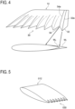
- FIG. 4 is a perspective view showing the serration portion 30.
- the serration portion 30 is configured to have a saw-teeth shape where a mountain portion 32 and a valley portion 34 are arranged alternately in the blade longitudinal direction on the trailing edge 22.
- the chord-directional cross section along the chord direction of the wind turbine blade 12 is formed to have an airfoil shape at any position.
- the serration portion 30 is disposed on at least a part of the trailing edge 22 of the wind turbine blade 12, and thus the aerodynamic performance does not deteriorate, unlike the typical flat serration portion. Nevertheless, similarly to the typical three-dimensional serration portion, the lift-drag ratio can be improved and a high aerodynamic performance can be maintained. Furthermore, unlike the typical three-dimensional serration portion, there is no acute surface at the valley portion 34, and thus it is possible to suppress occurrence of tonal sounds.
- W 1 indicates the exterior shape of the chord-directional cross section including the tip portion of the mountain portion 32 and the ridge line 32a of the mountain portion 32
- W 2 indicates the exterior shape of the chord-directional cross section including the valley line 34a that connects the deepest portion of the valley portion 34.
- the exterior shape of each of the cross sections W 1 and W 2 has an airfoil shape in the entire region of the exterior shape.
- a chord-directional cross section positioned between the two chord-directional cross sections has an airfoil shape in the entire region of the exterior shape. According to the example depicted in FIG.
- any chord-directional cross section in the region from the tip portion of the mountain portion 32 to the deepest portion of the valley portion 34 being formed to have an airfoil shape it is possible to improve the lift-drag ratio and maintain a high aerodynamic force like the typical three-dimensional serration portion, while effectively suppressing tonal sounds.
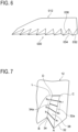
- FIG. 5 is a perspective view showing a wind turbine blade 012 including a typical three-dimensional serration portion 030.
- FIG. 6 is a perspective view showing the serration portion 030.
- a typical three-dimensional serration portion 030 does not have an airfoil shape over the entire region of the chord-directional cross section, unlike the above serration portion 30. That is, only the chord-directional cross section passing through the tip portion of the mountain portion 032 has an airfoil shape, and the chord-directional cross section passing through the other region includes a surface 036 of an acute flat shape that does not form an airfoil shape. Thus, when wind passes through the surface 036, tonal sounds are generated.
- airfoil shape refers to a shape whose thickness changes gradually in the chord-directional cross section of the wind turbine blade 12, and has no section where the thickness changes discontinuously like the surface 036 of the serration portion 030. That is, “airfoil shape” is a shape whose thickness changes continuously. In other words, “airfoil shape” is a shape that does not have discontinuous points for which two different tangents can be set, except for the leading edge and the trailing edge, on the outer shape of the chord-directional cross section. Accordingly, the flow passing through the trailing-edge side portion of the wind turbine blade 12 is not disturbed, and thus it is possible to suppress occurrence of tonal sounds.
- the drawing shows a chord-directional cross section of the trailing edge 22 before the ridge line 32a forms the serration portion 30.
- the line L indicates a portion where the chord-directional cross sections before and after notching are in contact with one another in the region between the ridge line 32a and the valley line 34a.
- A indicates the tip portion of the mountain portion 32
- B indicates the deepest portion of the valley portion 34.
- C indicates the intersection between the ridge line 32a and the line L
- D indicates the intersection between the valley line 34a and the line L.
- the ridge line 32a between A and C and the valley line 34a between B and D are each divided equally into N parts, thereby forming points a 1 , a 2 , ..., a N-1 , and b 1 , b 2 , ..., b N-1 .
- lines connecting the above respective points a 1 b 1 , a 2 b 2 , ..., a N-1 b N-1 are drawn on the surface 38, and the surface between the ridge line 32a and the valley line 34a is determined, where N is infinite ( ⁇ ).
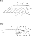
- FIG. 8 is a perspective view showing an attachment member 40 being a single member according to an embodiment (attachment member for a wind turbine blade).
- FIG. 9 is a schematic cross-sectional view taken along line A-A in FIG. 8 .
- the serration portion 30 is configured as an attachment member 40 to be attached to at least a part of the trailing edge 22 of the wind turbine blade 12. Accordingly, it is possible to form the serration portion 30 as needed, on the trailing edge 22 of the wind turbine blade 12 that does not have the serration portion 30.
- the attachment member 40 includes a first-surface side wall surface 42 to be disposed on the first surface 24 of the wind turbine blade 12, and a second-surface side wall surface 44 to be disposed on the second surface 26 of the wind turbine blade 12.
- the second-surface side wall surface 44 is connected to the first-surface side wall surface 42 via the trailing edge portion.
- the attachment member 40 is attached to the wind turbine blade 12 so as to cover the trailing edge portion of the wind turbine blade 12. With the attachment member 40 disposed so as to sandwich the trailing edge portion of the wind turbine blade 12 with the first-surface side wall surface 42 and the second-surface side wall surface 44 from both sides, it is possible to provide the serration portion 30 for the trailing edge 22 that does not have the serration portion 30.
- the serration portion 30 as needed, on the trailing edge 22 of the wind turbine blade 12 that does not have the serration portion 30. Furthermore, since the first-surface side wall surface 42 and the second-surface side wall surface 44 of the attachment member 40 serve as the blade surfaces of the wind turbine blade 12, the aerodynamic performance of the wind turbine blade 12 is not deteriorated.
- the tip portion of the first-surface side wall surface 42 is positioned at the point Pf, and is joined to the first surface 24 of the wind turbine blade 12 at the point Pf. Furthermore, the tip portion of the second-surface side wall surface 44 is positioned at the point Pr, and is joined to the second surface 26 at the point Pr. In an embodiment, the point Pf coincides with the line L depicted in FIG. 7 in the chord direction.
- the angle ⁇ 1 formed between the tangent t 1 to the deepest portion of the valley portion 34 at the side of the first surface 24 and the tangent t 2 to the deepest portion of the valley portion 34 at the side of the second surface 26 is not greater than 45 angular degrees. Accordingly, the tonal sounds are suppressed, and thereby it is possible to improve the effect of the serration portion 30 to reduce broadband noise.
- the angle ⁇ 1 is not greater than 35 angular degrees, and more preferably, 30 angular degrees. Accordingly, it is possible to improve the effect to reduce noise even further.
- the angle formed between the tangent t 3 at the side of the first surface 24 and the tangent t 4 at the side of the second surface 26 is ⁇ 2 .
- the lower limit value of the angle ⁇ 1 is the angle ⁇ 2 of the trailing edge 22 of the original wind turbine blade 12.
- the upper limit value of the angle ⁇ 1 is the angle ⁇ 2 of the trailing edge 22 of the original wind turbine blade 12.
- first surface 24 of the wind turbine blade 12 has a convex surface
- second surface 26 has a convex surface
- first surface 24 of the wind turbine blade 12 has a convex surface
- second surface 26 has a concave surface
- the attachment member 40 is formed of a material that has a flexibility that is equal to or higher than that of the wind turbine blade 12.
- a weather-resistant and durable rubber material such as ethylene propylene diene monomer (EPDM), and urethane, or a sponge material may be used. Accordingly, even when the wind turbine blade 12 is twisted in response to wind and has warp or tension, the attachment member 40 can also deform so as to conform to the deformation of the wind turbine blade 12.
- EPDM ethylene propylene diene monomer
- urethane urethane
- the attachment member 40 can also deform so as to conform to the deformation of the wind turbine blade 12.
- it is possible to improve the weather resistant performance and the load durability of the attachment member 40 and thereby it is possible to prevent breakage of the serration portion 30 and separation of the serration portion 30 from the wind turbine blade 12.
- there is no clearance between the wind turbine blade 12 and the attachment member 40 and thus it is possible to suppress occurrence of new noise due to the flow around such clearance.
- the elastic modulus (Young's modulus) can be used as an index of the flexibility of the material of the attachment member 40.
- the Young's modulus of the material that can be applied to the attachment member 40 may be equal to or not higher than the Young's modulus of the material constituting the wind turbine blade 12.
- the lift-drag ratio (lift coefficient / drag coefficient) is compared between a wind turbine blade without the serration portion and the wind turbine blade 12 having the serration portion 30
- the lift-drag ratio of the wind turbine blade without the serration portion 30 is 28.9
- the lift-drag ratio of the wind turbine blade 12 having the serration portion 30 is 29.8, which indicates improvement of the lift-drag ratio.
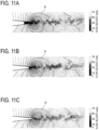
- FIGs. 10A to 10C are analysis results showing the flow-velocity distribution and the pressure distribution of the flow of wind at the serration portion 30, for the wind turbine blade 12 having the serration portion 30.
- FIGs. 11A to 11C are analysis results showing the flow-velocity distribution and the pressure distribution of the flow of wind at the serration portion 030, for the wind turbine blade 012 having the typical three-dimensional serration portion 030.
- FIG.s 10A and 11A show the analysis result of the flow in the chord-directional cross section including the valley line 34a.
- FIG.s 10C and 11C show the analysis result of the flow in the chord-directional cross section including the ridge line 32a.
- FIG.s 10B and 11B show the analysis result of the flow in the chord-directional cross section between the valley line 34a and the ridge line 32a.
- the line 'p' is the isobaric line.
- the angle formed between the tangent to the deepest portion of the valley portion at the side of the first surface and the tangent to the deepest portion of the valley portion at the side of the second surface is not greater than 45 angular degrees, and thereby it is possible to reduce broadband noise.
- the attachment member includes a material having a flexibility which is equal to or higher than that of the wind turbine blade body.
- the attachment member for a wind turbine blade is formed of a material having a flexibility that is equal to or higher than that of the wind turbine blade body, and thus the attachment member for a wind turbine blade is capable of deforming so as to conform to the twist and tension of the wind turbine blade body in response to wind, and thereby it is possible to improve the durability.
Description
- The present disclosure relates to a wind turbine blade apparatus.
- For a wind turbine blade assembly to be attached to a wind turbine rotor, there has been a technique to provide a serration portion having a saw-teeth shape where mountain portions and valley portions are disposed alternately in the blade longitudinal direction on at least a part of the trailing edge of the wind turbine blade body, to suppress fluctuation of a flow at the downstream side of the wind turbine blade body and suppress broadband noise. As the above techniques,
US 7 059 833 B discloses a flat serration portion formed of a flat plate, andUS 5 533 865 A discloses a three-dimensional serration portion which is formed three dimensionally. -
EP 2 921 697 A1 -
EP 2 028 366 A1EP 0 652 367 A1WO 2018/103803 A1 each disclose a wind turbine blade with a trailing edge portion that has - at least in some chord-directional cross sections - discontinuous points for which two different tangents can be set, i.e. which have essentially perpendicular flat surfaces facing towards the rear side. -
EP 2 667 019 A2 - A flat serration portion may lead to deterioration of the aerodynamic performance of the wind turbine blade body, and tends to have an insufficient strength. Although having no risk of deterioration of the aerodynamic performance of the wind turbine blade body, a three-dimensional serration portion has an acute surface that does not continue to the blade surface at the deeply notched part of the valley portion. Thus, a flow passing through the acute surface generates alternate vortices, which may generate tonal sounds (noise close to pure tone).
- The present disclosure was made in view of the above, and an object of the present disclosure is to solve the noise problem of a wind turbine blade apparatus including a serration portion disposed on the wind turbine blade body, without deteriorating the aerodynamic performance.
- According to the present invention, a wind turbine blade apparatus has the features of
claim 1 including inter alia a wind turbine blade body, wherein a serration portion is disposed on at least a part of a trailing edge of the wind turbine blade body, the serration portion having a saw-teeth shape where a mountain portion and a valley portion are arranged alternately in a blade longitudinal direction, and wherein a chord-directional cross section of the wind turbine blade body along a chord direction is formed to have an airfoil shape at any position in a region from the mountain portion to the valley portion. - Furthermore, according to the present invention, the attachment member attached to at least a part of a trailing edge of a wind turbine blade body includes: a first-surface side wall surface disposed on a first surface of the wind turbine blade body; and a second-surface side wall surface disposed on a second surface of the wind turbine blade body, the second-surface side wall surface being connected to the first-surface side wall surface via a trailing edge portion, wherein trailing-edge portion sides of the first-surface side wall surface and the second-surface side wall surface are formed into a saw-teeth shape where a mountain portion and a valley portion are arranged alternately, and wherein a chord-directional cross section of the wind turbine blade body along a chord direction is formed to have an airfoil shape at any position in a region from the tip portion of the mountain portion to the deepest portion of the valley portion.
- With the wind turbine blade apparatus according to the present invention, it is possible to reduce broadband noise, while improving the lift-drag ratio (lift coefficient / drag coefficient) and maintaining a high aerodynamic performance. Furthermore, unlike the typical three-dimensional serration portion, it is possible to suppress occurrence of tonal sounds.
-
-
FIG. 1 is a side view of a wind turbine power generating apparatus with a wind turbine blade apparatus according to an example serving to explain aspects of the invention. -
FIG. 2 is a perspective view of a wind turbine blade apparatus according to an example serving to explain aspects of the invention. -
FIG. 3 is a partial perspective view of a wind turbine blade apparatus according to an example serving to explain aspects of the invention. -
FIG. 4 is a perspective view of a serration portion according to an example serving to explain aspects of the invention. -
FIG. 5 is a partial perspective view of a wind turbine blade apparatus including a typical three-dimensional serration portion. -
FIG. 6 is a perspective view showing a typical three-dimensional serration portion. -
FIG. 7 is an explanatory diagram for explaining a method for obtaining a configuration surface of a serration portion. -
FIG. 8 is a perspective view showing an attachment member for a wind turbine blade according to an embodiment. -
FIG. 9 is a schematic cross-sectional view taken along line A-A inFIG. 8 . -
FIG. 10A is a distribution diagram showing the flow at the downstream side of a wind turbine blade apparatus according to an embodiment. -
FIG. 10B is a distribution diagram showing the flow at the downstream side of a wind turbine blade apparatus according to an embodiment. -
FIG. 10C is a distribution diagram showing the flow at the downstream side of a wind turbine blade apparatus according to an embodiment. -
FIG. 11A is a distribution diagram showing the flow at the downstream side of a wind turbine blade apparatus that includes a typical three-dimensional serration portion. -
FIG. 11B is a distribution diagram showing the flow at the downstream side of a wind turbine blade apparatus that includes a typical three-dimensional serration portion. -
FIG. 11C is a distribution diagram showing the flow at the downstream side of a wind turbine blade apparatus that includes a typical three-dimensional serration portion. - Embodiments of the present invention and examples serving to explain aspects of the invention will now be described in detail with reference to the accompanying drawings.
- For instance, an expression of relative or absolute arrangement such as "in a direction", "along a direction", "parallel", "orthogonal", "centered", "concentric" and "coaxial" shall not be construed as indicating only the arrangement in a strict literal sense, but also includes a state where the arrangement is relatively displaced by a tolerance, or by an angle or a distance whereby it is possible to achieve the same function.
- For instance, an expression of an equal state such as "same" "equal" and "uniform" shall not be construed as indicating only the state in which the feature is strictly equal, but also includes a state in which there is a tolerance or a difference that can still achieve the same function.
- Further, for instance, an expression of a shape such as a rectangular shape or a cylindrical shape shall not be construed as only the geometrically strict shape, but also includes a shape with unevenness or chamfered corners within the range in which the same effect can be achieved.
- On the other hand, an expression such as "comprise", "include", "have", "contain" and "constitute" are not intended to be exclusive of other components.
-
FIG. 1 is a side view of a wind turbine power generating apparatus with a wind turbine blade apparatus according to an example serving to explain aspects of the invention.FIG. 2 is a perspective view of a wind turbine blade apparatus according to an example serving to explain aspects of the invention. As depicted inFIG. 1 , a wind turbinepower generating apparatus 100 includes at least one (e.g. three) windturbine blade apparatuses 10. The windturbine blade apparatuses 10 are mounted to ahub 104 in a radial fashion, and the windturbine blade apparatuses 10 and thehub 104 constitute arotor 102. As the windturbine blade apparatuses 10 receive wind, a generator (not depicted) coupled to therotor 102 generates electric power. Therotor 102 is supported by anacelle 108 disposed on an upper part of atower 106. Further, thetower 106 is disposed upright on a base structure (foundation structure or a floating structure, for example) 110 disposed on water or on land. - As depicted in
FIG. 2 , the windturbine blade apparatus 10 includes a wind turbine blade 12 (wind turbine blade body). Thewind turbine blade 12 includes ablade root 14 to be attached to thehub 104, ablade tip 16 positioned farthest from thehub 104, and anairfoil portion 18 extending between theblade root 14 and theblade tip 16. Thewind turbine blade 12 has a leadingedge 20 and atrailing edge 22 from theblade root 14 to theblade tip 16. The exterior shape of thewind turbine blade 12 is formed by afirst surface 24 and asecond surface 26 disposed opposite to thefirst surface 24. The windturbine blade apparatus 10 includes aserration portion 30 having a saw-teeth shape, on at least a part of thetrailing edge 22 of thewind turbine blade 12. As depicted inFIG. 2 , for instance, theserration portion 30 is disposed on the blade tip side, where the circumferential speed becomes high due to rotation of therotor 102, and noise and deterioration of the aerodynamic performance are remarkable. When the wind flows in the direction of the arrow X and thewind turbine blade 12 receives the force of the wind and rotates in the direction of the arrow Y, thefirst surface 24 is the pressure surface and thesecond surface 26 is the suction surface. -
FIG. 3 is a perspective view showing a section of thewind turbine blade 12 that includes theserration portion 30 disposed on thetrailing edge 22.FIG. 4 is a perspective view showing theserration portion 30. As depicted inFIG. 3 , theserration portion 30 is configured to have a saw-teeth shape where amountain portion 32 and avalley portion 34 are arranged alternately in the blade longitudinal direction on the trailingedge 22. Further, as depicted inFIG. 4 , in the region from themountain portion 32 to thevalley portion 34, the chord-directional cross section along the chord direction of thewind turbine blade 12 is formed to have an airfoil shape at any position. - With the above configuration, the
serration portion 30 is disposed on at least a part of the trailingedge 22 of thewind turbine blade 12, and thus the aerodynamic performance does not deteriorate, unlike the typical flat serration portion. Nevertheless, similarly to the typical three-dimensional serration portion, the lift-drag ratio can be improved and a high aerodynamic performance can be maintained. Furthermore, unlike the typical three-dimensional serration portion, there is no acute surface at thevalley portion 34, and thus it is possible to suppress occurrence of tonal sounds. - In
FIG. 4 , W1 indicates the exterior shape of the chord-directional cross section including the tip portion of themountain portion 32 and theridge line 32a of themountain portion 32, and W2 indicates the exterior shape of the chord-directional cross section including thevalley line 34a that connects the deepest portion of thevalley portion 34. The exterior shape of each of the cross sections W1 and W2 has an airfoil shape in the entire region of the exterior shape. Besides the above two chord-directional cross sections, a chord-directional cross section positioned between the two chord-directional cross sections has an airfoil shape in the entire region of the exterior shape. According to the example depicted inFIG. 4 , with any chord-directional cross section in the region from the tip portion of themountain portion 32 to the deepest portion of thevalley portion 34 being formed to have an airfoil shape, it is possible to improve the lift-drag ratio and maintain a high aerodynamic force like the typical three-dimensional serration portion, while effectively suppressing tonal sounds. -
FIG. 5 is a perspective view showing awind turbine blade 012 including a typical three-dimensional serration portion 030.FIG. 6 is a perspective view showing theserration portion 030. A typical three-dimensional serration portion 030 does not have an airfoil shape over the entire region of the chord-directional cross section, unlike theabove serration portion 30. That is, only the chord-directional cross section passing through the tip portion of themountain portion 032 has an airfoil shape, and the chord-directional cross section passing through the other region includes asurface 036 of an acute flat shape that does not form an airfoil shape. Thus, when wind passes through thesurface 036, tonal sounds are generated. - In the present specification, "airfoil shape" refers to a shape whose thickness changes gradually in the chord-directional cross section of the
wind turbine blade 12, and has no section where the thickness changes discontinuously like thesurface 036 of theserration portion 030. That is, "airfoil shape" is a shape whose thickness changes continuously. In other words, "airfoil shape" is a shape that does not have discontinuous points for which two different tangents can be set, except for the leading edge and the trailing edge, on the outer shape of the chord-directional cross section. Accordingly, the flow passing through the trailing-edge side portion of thewind turbine blade 12 is not disturbed, and thus it is possible to suppress occurrence of tonal sounds. - Next, with reference to
FIG. 7 , a method for setting the shape of thesurface 38 between theridge line 32a and thevalley line 34a of theserration portion 30 will be described. The drawing shows a chord-directional cross section of the trailingedge 22 before theridge line 32a forms theserration portion 30. When the trailingedge 22 corresponding to thevalley portion 34 is notched to form thevalley portion 34, the line L indicates a portion where the chord-directional cross sections before and after notching are in contact with one another in the region between theridge line 32a and thevalley line 34a. Herein, A indicates the tip portion of themountain portion 32, and B indicates the deepest portion of thevalley portion 34. Furthermore, C indicates the intersection between theridge line 32a and the line L, and D indicates the intersection between thevalley line 34a and the line L. - First, the
ridge line 32a between A and C and thevalley line 34a between B and D are each divided equally into N parts, thereby forming points a1, a2, ..., aN-1, and b1, b2, ..., bN-1. Next, lines connecting the above respective points a1b1, a2b2, ..., aN-1bN-1 are drawn on thesurface 38, and the surface between theridge line 32a and thevalley line 34a is determined, where N is infinite (∞). -
FIG. 8 is a perspective view showing anattachment member 40 being a single member according to an embodiment (attachment member for a wind turbine blade).FIG. 9 is a schematic cross-sectional view taken along line A-A inFIG. 8 . Theserration portion 30 is configured as anattachment member 40 to be attached to at least a part of the trailingedge 22 of thewind turbine blade 12. Accordingly, it is possible to form theserration portion 30 as needed, on the trailingedge 22 of thewind turbine blade 12 that does not have theserration portion 30. - In an embodiment, as depicted in
FIG. 8 , theattachment member 40 includes a first-surfaceside wall surface 42 to be disposed on thefirst surface 24 of thewind turbine blade 12, and a second-surfaceside wall surface 44 to be disposed on thesecond surface 26 of thewind turbine blade 12. The second-surfaceside wall surface 44 is connected to the first-surfaceside wall surface 42 via the trailing edge portion. Theattachment member 40 is attached to thewind turbine blade 12 so as to cover the trailing edge portion of thewind turbine blade 12. With theattachment member 40 disposed so as to sandwich the trailing edge portion of thewind turbine blade 12 with the first-surfaceside wall surface 42 and the second-surface side wall surface 44 from both sides, it is possible to provide theserration portion 30 for the trailingedge 22 that does not have theserration portion 30. Accordingly, it is possible to provide theserration portion 30 as needed, on the trailingedge 22 of thewind turbine blade 12 that does not have theserration portion 30. Furthermore, since the first-surfaceside wall surface 42 and the second-surfaceside wall surface 44 of theattachment member 40 serve as the blade surfaces of thewind turbine blade 12, the aerodynamic performance of thewind turbine blade 12 is not deteriorated. - In an embodiment, as depicted in
FIG. 9 , the tip portion of the first-surfaceside wall surface 42 is positioned at the point Pf, and is joined to thefirst surface 24 of thewind turbine blade 12 at the point Pf. Furthermore, the tip portion of the second-surfaceside wall surface 44 is positioned at the point Pr, and is joined to thesecond surface 26 at the point Pr. In an embodiment, the point Pf coincides with the line L depicted inFIG. 7 in the chord direction. - In an embodiment, as depicted in
FIG. 9 , the angle θ1 formed between the tangent t1 to the deepest portion of thevalley portion 34 at the side of thefirst surface 24 and the tangent t2 to the deepest portion of thevalley portion 34 at the side of thesecond surface 26 is not greater than 45 angular degrees. Accordingly, the tonal sounds are suppressed, and thereby it is possible to improve the effect of theserration portion 30 to reduce broadband noise. Preferably, the angle θ1 is not greater than 35 angular degrees, and more preferably, 30 angular degrees. Accordingly, it is possible to improve the effect to reduce noise even further. Moreover, at the trailingedge 22 of the originalwind turbine blade 12, the angle formed between the tangent t3 at the side of thefirst surface 24 and the tangent t4 at the side of thesecond surface 26 is θ2. In a case where awind turbine blade 12 without theserration portion 30 is notched to form theserration portion 30, the lower limit value of the angle θ1 is the angle θ2 of the trailingedge 22 of the originalwind turbine blade 12. In a case where theserration portion 30 is formed by attaching theattachment member 40 to a trailing-edge side of awind turbine blade 12 without theserration portion 30 while thewind turbine blade 12 is not notched, the upper limit value of the angle θ1 is the angle θ2 of the trailingedge 22 of the originalwind turbine blade 12. - In an embodiment, the
first surface 24 of thewind turbine blade 12 has a convex surface, and thesecond surface 26 has a convex surface. In another embodiment, thefirst surface 24 of thewind turbine blade 12 has a convex surface, and thesecond surface 26 has a concave surface. - In an embodiment, the
attachment member 40 is formed of a material that has a flexibility that is equal to or higher than that of thewind turbine blade 12. As theattachment member 40, for instance, a weather-resistant and durable rubber material such as ethylene propylene diene monomer (EPDM), and urethane, or a sponge material may be used. Accordingly, even when thewind turbine blade 12 is twisted in response to wind and has warp or tension, theattachment member 40 can also deform so as to conform to the deformation of thewind turbine blade 12. Thus, it is possible to improve the weather resistant performance and the load durability of theattachment member 40, and thereby it is possible to prevent breakage of theserration portion 30 and separation of theserration portion 30 from thewind turbine blade 12. Furthermore, there is no clearance between thewind turbine blade 12 and theattachment member 40, and thus it is possible to suppress occurrence of new noise due to the flow around such clearance. - The elastic modulus (Young's modulus) can be used as an index of the flexibility of the material of the
attachment member 40. The Young's modulus of the material that can be applied to theattachment member 40 may be equal to or not higher than the Young's modulus of the material constituting thewind turbine blade 12. - Hereinafter, the result of analysis conducted by the present inventors and the like will be described. When the lift-drag ratio (lift coefficient / drag coefficient) is compared between a wind turbine blade without the serration portion and the
wind turbine blade 12 having theserration portion 30, the lift-drag ratio of the wind turbine blade without theserration portion 30 is 28.9, and the lift-drag ratio of thewind turbine blade 12 having theserration portion 30 is 29.8, which indicates improvement of the lift-drag ratio. -
FIGs. 10A to 10C are analysis results showing the flow-velocity distribution and the pressure distribution of the flow of wind at theserration portion 30, for thewind turbine blade 12 having theserration portion 30.FIGs. 11A to 11C are analysis results showing the flow-velocity distribution and the pressure distribution of the flow of wind at theserration portion 030, for thewind turbine blade 012 having the typical three-dimensional serration portion 030.FIG.s 10A and11A show the analysis result of the flow in the chord-directional cross section including thevalley line 34a.FIG.s 10C and11C show the analysis result of the flow in the chord-directional cross section including theridge line 32a.FIG.s 10B and11B show the analysis result of the flow in the chord-directional cross section between thevalley line 34a and theridge line 32a. In the above drawings, the line 'p' is the isobaric line. - From the above drawings, it can be seen that the vortices emitted from the
serration portion 30 are more reduced than the vortices emitted from the typical three-dimensional serration portion 030. Thus, it can be also confirmed that noise such as tonal sounds is also reduced. - The contents described in the above respective embodiments and examples can be understood as follows, for instance.
- (1) According to the invention, a wind turbine blade apparatus (the wind
turbine blade apparatus 10 depicted inFIG. 2 , for instance) at least includes a wind turbine blade body, wherein a serration portion (theserration portion 30 depicted inFIG.s 2 to 4 , for instance) is disposed on at least on a part of a trailing edge of the wind turbine blade body, the serration portion having a saw-teeth shape where a mountain portion and a valley portion are arranged alternately in a blade longitudinal direction, and wherein a chord-directional cross section (the chord-directional cross sections W1 and W2 depicted inFIG. 4 , for instance) of the wind turbine blade body along a chord direction is formed to have an airfoil shape at any position in a region from the mountain portion to the valley portion.
With the above configuration, the chord-directional cross section along the chord direction of the wind turbine blade body is formed to have an airfoil shape at any position in the region from the tip portion of the mountain portion to the deepest portion of the valley portion, and thus the aerodynamic performance does not deteriorate unlike the typical three-dimensional serration portion, and it is possible to improve the lift-drag ratio and maintain a high aerodynamic force like the typical three-dimensional serration portion. Furthermore, unlike the typical three-dimensional serration portion, there is no acute portion at the valley portion, and thus it is possible to suppress occurrence of tonal sound. - (2) According to a the invention, the wind turbine blade apparatus is configured such that the airfoil shape is formed in a region from a tip portion of the mountain portion to a deepest portion of the valley portion.
With the above configuration, it is possible to improve the lift-drag ratio and maintain a high aerodynamic force like the typical three-dimensional serration portion, while effectively suppressing occurrence of tonal sounds. - (3) According to the invention, the wind turbine blade apparatus is configured such that the airfoil shape is a shape whose thickness changes continuously in the chord-directional cross section.
With the above configuration, the flow passing through the trailing-edge side portion of thewind turbine blade 12 is not disturbed, and thus it is possible to suppress occurrence of tonal sounds. - (4) According to the invention, the wind turbine blade apparatus according is configured such that the serration portion is configured as an attachment member (the
attachment member 40 depicted inFIG. 8 , for instance) to be attached to at least a part of the trailing edge of the wind turbine blade body.
With the above configuration, by attaching the attachment member as needed to the trailing edge of a wind turbine blade body that does not include the serration portion, it is possible to achieve the above advantageous effect. - (5) According to the invention, the wind turbine blade apparatus according to the above (4) is configured such that the attachment member includes: a first-surface side wall surface (the first-surface
side wall surface 42 depicted inFIG. 4 , for instance) to be disposed on a first surface of the wind turbine blade body; and a second-surface side wall surface (the second-surfaceside wall surface 44 depicted inFIG. 4 , for instance) to be disposed on a second surface of the wind turbine blade body, the second-surface side wall surface being connected to the first-surface side wall surface via a trailing edge portion, and the attachment member is configured to be attached to the wind turbine blade body so as to cover a trailing-edge side portion of the wind turbine blade body.
With the above configuration, the attachment member for a wind turbine blade can be easily attached to the trailing edge of the wind turbine blade body, by sandwiching the trailing-edge side portion of the wind turbine blade body without the serration portion with the first-surface side wall surface and the second-surface side wall surface from both sides. Furthermore, since the first-surface side wall surface and the second-surface side wall surface of the attachment member for a wind turbine blade serve as the blade surfaces of the wind turbine blade, the aerodynamic performance of the wind turbine blade is not deteriorated. - (6) According to yet another preferred embodiment, the wind turbine blade apparatus according to any one of the above (1) to (5) is configured such that an angle formed between a tangent (the tangent t1 depicted in
FIG. 4 , for instance) to a deepest portion of the valley portion (thevalley portion 34, for instance) at the side of a first surface and a tangent (the tangent t2 depicted inFIG. 4 , for instance) to the deepest portion of the valley portion at the side of a second surface is not greater than 45 angular degrees. - With the above configuration, the angle formed between the tangent to the deepest portion of the valley portion at the side of the first surface and the tangent to the deepest portion of the valley portion at the side of the second surface is not greater than 45 angular degrees, and thereby it is possible to reduce broadband noise.
- (8) According to another preferred embodiment, the attachment member includes a material having a flexibility which is equal to or higher than that of the wind turbine blade body.
- With the above configuration, the attachment member for a wind turbine blade is formed of a material having a flexibility that is equal to or higher than that of the wind turbine blade body, and thus the attachment member for a wind turbine blade is capable of deforming so as to conform to the twist and tension of the wind turbine blade body in response to wind, and thereby it is possible to improve the durability.
Claims (4)
- A wind turbine blade apparatus (10) comprising:a wind turbine blade body (12) having a leading edge (20) and a trailing edge (22) and an exterior shape which is formed by a first surface (24) and a second surface (26) disposed opposite to the first surface (24),wherein a serration portion (30) is disposed on at least a part of the trailing edge (22) of the wind turbine blade body (12), the serration portion (30) having a saw-teeth shape where a mountain portion (32) and a valley portion (34) are arranged alternately in a blade longitudinal direction,wherein the serration portion (30) is configured as an attachment member (40) attached to at least a part of the trailing edge (22) of the wind turbine blade body (12) so as to cover a trailing-edge side portion of the wind turbine blade body (12),wherein the attachment member (40) includes:a first-surface side wall surface (42) disposed on the first surface (24) of the wind turbine blade body (12); anda second-surface side wall surface (44) disposed on the second surface (26) of the wind turbine blade body (12), the second-surface side wall surface (44) being connected to the first-surface side wall surface (42) via a trailing edge portion,wherein trailing-edge portion sides of the first-surface side wall surface (42) and the second-surface side wall surface (44) are formed into a saw-teeth shape where a mountain portion (32) and a valley portion (34) are arranged alternately, and wherein a chord-directional cross section of the wind turbine blade body (12) along a chord direction is formed to have an airfoil shape at any position in a region from a tip portion of the mountain portion (32) to a deepest portion of the valley portion (34),wherein the airfoil shape is a shape whose thickness changes continuously in the chord-directional cross section and does not have discontinuous points for which two different tangents can be set, except for the trailing edge (22) and the leading edge (20), on the outer shape of the chord-directional cross section, andwherein the mountain portions (32) and the valley portions (34) formed on the trailing-edge portion sides of the first-surface side wall surface (42) and the second-surface side wall surface (44) are respectively aligned along the chord direction.
- The wind turbine blade apparatus (10) according to claim 1,
wherein each of the first surface (24) and the second surface (26) of the wind turbine blade body (12) has a convex shape. - The wind turbine blade apparatus (10) according to claim 1 or 2,
wherein an angle (θ1) formed between a tangent (t1) to the deepest portion of the valley portion (34) at the side of the first surface (24) and a tangent (t2) to the deepest portion of the valley portion (34) at the side of the second surface (26) is not greater than 45 angular degrees. - The wind turbine blade apparatus (10) according to any one of claims 1 to 3,
wherein the attachment member (40) comprises a material having a flexibility which is equal to or higher than that of the wind turbine blade body (12).
Applications Claiming Priority (1)
| Application Number | Priority Date | Filing Date | Title |
|---|---|---|---|
| JP2019158694A JP7277316B2 (en) | 2019-08-30 | 2019-08-30 | Wind turbine blade device and wind turbine blade attachment member |
Publications (2)
| Publication Number | Publication Date |
|---|---|
| EP3786444A1 EP3786444A1 (en) | 2021-03-03 |
| EP3786444B1 true EP3786444B1 (en) | 2024-04-03 |
Family
ID=69500639
Family Applications (1)
| Application Number | Title | Priority Date | Filing Date |
|---|---|---|---|
| EP20155713.9A Active EP3786444B1 (en) | 2019-08-30 | 2020-02-05 | Wind turbine blade apparatus |
Country Status (3)
| Country | Link |
|---|---|
| US (1) | US11300097B2 (en) |
| EP (1) | EP3786444B1 (en) |
| JP (1) | JP7277316B2 (en) |
Families Citing this family (1)
| Publication number | Priority date | Publication date | Assignee | Title |
|---|---|---|---|---|
| CN114294086A (en) * | 2021-12-15 | 2022-04-08 | 华南理工大学 | Cooling fan with blade tip sawtooth structure and calculation method of aerodynamic noise of cooling fan |
Family Cites Families (17)
| Publication number | Priority date | Publication date | Assignee | Title |
|---|---|---|---|---|
| US4830315A (en) * | 1986-04-30 | 1989-05-16 | United Technologies Corporation | Airfoil-shaped body |
| US4813633A (en) * | 1986-12-29 | 1989-03-21 | United Technologies Corporation | Airfoil trailing edge |
| US5088665A (en) * | 1989-10-31 | 1992-02-18 | The United States Of America As Represented By The Administrator Of The National Aeronautics And Space Administration | Serrated trailing edges for improving lift and drag characteristics of lifting surfaces |
| NL9301910A (en) | 1993-11-04 | 1995-06-01 | Stork Prod Eng | Wind turbine. |
| JPH11201021A (en) | 1998-01-06 | 1999-07-27 | Mitsubishi Heavy Ind Ltd | Wind mill vane |
| US7059833B2 (en) | 2001-11-26 | 2006-06-13 | Bonus Energy A/S | Method for improvement of the efficiency of a wind turbine rotor |
| EP1338793A3 (en) * | 2002-02-22 | 2010-09-01 | Mitsubishi Heavy Industries, Ltd. | Serrated wind turbine blade trailing edge |
| DK176352B1 (en) * | 2005-12-20 | 2007-09-10 | Lm Glasfiber As | Profile series for blade for wind turbines |
| US7918653B2 (en) * | 2007-02-07 | 2011-04-05 | General Electric Company | Rotor blade trailing edge assemby and method of use |
| ES2345583B1 (en) | 2007-05-31 | 2011-07-28 | GAMESA INNOVATION & TECHNOLOGY, S.L. | AEROGENERATOR SHOVEL WITH ANTI-NOISE DEVICES. |
| US8414261B2 (en) | 2011-05-31 | 2013-04-09 | General Electric Company | Noise reducer for rotor blade in wind turbine |
| DK177533B1 (en) | 2012-05-25 | 2013-09-08 | Envision Energy Denmark Aps | Trailing edge tape |
| JP2015075062A (en) | 2013-10-11 | 2015-04-20 | 株式会社日立製作所 | Axial flow type blade, and wind power generation apparatus using the same |
| US9670901B2 (en) | 2014-03-21 | 2017-06-06 | Siemens Aktiengesellschaft | Trailing edge modifications for wind turbine airfoil |
| US9476406B2 (en) * | 2014-04-14 | 2016-10-25 | Siemens Aktiengesellschaft | Vortex generators aligned with trailing edge features on wind turbine blade |
| US10240576B2 (en) * | 2015-11-25 | 2019-03-26 | General Electric Company | Wind turbine noise reduction with acoustically absorbent serrations |
| WO2018103803A1 (en) | 2016-12-06 | 2018-06-14 | Vestas Wind Systems A/S | A wind turbine blade having a truncated trailing edge |
-
2019
- 2019-08-30 JP JP2019158694A patent/JP7277316B2/en active Active
-
2020
- 2020-02-04 US US16/781,327 patent/US11300097B2/en active Active
- 2020-02-05 EP EP20155713.9A patent/EP3786444B1/en active Active
Also Published As
| Publication number | Publication date |
|---|---|
| US11300097B2 (en) | 2022-04-12 |
| JP2021038675A (en) | 2021-03-11 |
| JP7277316B2 (en) | 2023-05-18 |
| EP3786444A1 (en) | 2021-03-03 |
| US20210062781A1 (en) | 2021-03-04 |
Similar Documents
| Publication | Publication Date | Title |
|---|---|---|
| US11204015B2 (en) | Serrated trailing edge panel for a wind turbine blade | |
| US8550786B2 (en) | Vertical axis wind turbine with self-starting capabilities | |
| US10087912B2 (en) | Vortex generator for a rotor blade | |
| US20110150664A1 (en) | Aeroacoustic rotor blade for a wind turbine, and wind turbine equipped therewith | |
| EP2917571B1 (en) | A system and method for trailing edge noise reduction of a wind turbine blade | |
| KR100766729B1 (en) | Rotor blade for a wind power plant | |
| US20120189455A1 (en) | Wind turbine rotor blade element and wind turbine rotor blade | |
| EP3473850B1 (en) | Method for determining arrangement position of vortex generator on wind turbine blade, method for producing wind turbine blade assembly, and wind turbine blade assembly | |
| US11300096B2 (en) | Method for determining arrangement position of vortex generator on wind turbine blade, method for producing wind turbine blade assembly, and wind turbine blade assembly | |
| EP3786444B1 (en) | Wind turbine blade apparatus | |
| JP2009191744A (en) | Vertical shaft wind turbine | |
| US11661918B2 (en) | Noise reducer for a wind turbine rotor blade | |
| US20230279835A1 (en) | Wind turbine serrations with upstream extension | |
| US20240133358A1 (en) | Leading edge protection with reduced noise impact | |
| US11708813B2 (en) | Wind turbine rotor blade flow guiding device and wind turbine rotor blade | |
| CN116829829A (en) | Front edge protection device with reduced noise effects |
Legal Events
| Date | Code | Title | Description |
|---|---|---|---|
| PUAI | Public reference made under article 153(3) epc to a published international application that has entered the european phase |
Free format text: ORIGINAL CODE: 0009012 |
|
| STAA | Information on the status of an ep patent application or granted ep patent |
Free format text: STATUS: REQUEST FOR EXAMINATION WAS MADE |
|
| STAA | Information on the status of an ep patent application or granted ep patent |
Free format text: STATUS: EXAMINATION IS IN PROGRESS |
|
| 17P | Request for examination filed |
Effective date: 20210114 |
|
| AK | Designated contracting states |
Kind code of ref document: A1 Designated state(s): AL AT BE BG CH CY CZ DE DK EE ES FI FR GB GR HR HU IE IS IT LI LT LU LV MC MK MT NL NO PL PT RO RS SE SI SK SM TR |
|
| AX | Request for extension of the european patent |
Extension state: BA ME |
|
| 17Q | First examination report despatched |
Effective date: 20210208 |
|
| RIC1 | Information provided on ipc code assigned before grant |
Ipc: F03D 1/06 20060101AFI20230921BHEP |
|
| GRAP | Despatch of communication of intention to grant a patent |
Free format text: ORIGINAL CODE: EPIDOSNIGR1 |
|
| STAA | Information on the status of an ep patent application or granted ep patent |
Free format text: STATUS: GRANT OF PATENT IS INTENDED |
|
| INTG | Intention to grant announced |
Effective date: 20231116 |
|
| GRAS | Grant fee paid |
Free format text: ORIGINAL CODE: EPIDOSNIGR3 |
|
| GRAA | (expected) grant |
Free format text: ORIGINAL CODE: 0009210 |
|
| STAA | Information on the status of an ep patent application or granted ep patent |
Free format text: STATUS: THE PATENT HAS BEEN GRANTED |
|
| AK | Designated contracting states |
Kind code of ref document: B1 Designated state(s): AL AT BE BG CH CY CZ DE DK EE ES FI FR GB GR HR HU IE IS IT LI LT LU LV MC MK MT NL NO PL PT RO RS SE SI SK SM TR |
|
| REG | Reference to a national code |
Ref country code: CH Ref legal event code: EP |
|
| REG | Reference to a national code |
Ref country code: DE Ref legal event code: R096 Ref document number: 602020028156 Country of ref document: DE |