EP3786093A1 - Transportation equipment branch convergence device - Google Patents
Transportation equipment branch convergence device Download PDFInfo
- Publication number
- EP3786093A1 EP3786093A1 EP19818638.9A EP19818638A EP3786093A1 EP 3786093 A1 EP3786093 A1 EP 3786093A1 EP 19818638 A EP19818638 A EP 19818638A EP 3786093 A1 EP3786093 A1 EP 3786093A1
- Authority
- EP
- European Patent Office
- Prior art keywords
- arc
- conveyance means
- moving conveyance
- shaped
- vertically moving
- Prior art date
- Legal status (The legal status is an assumption and is not a legal conclusion. Google has not performed a legal analysis and makes no representation as to the accuracy of the status listed.)
- Granted
Links
Images





Classifications
-
- B—PERFORMING OPERATIONS; TRANSPORTING
- B65—CONVEYING; PACKING; STORING; HANDLING THIN OR FILAMENTARY MATERIAL
- B65G—TRANSPORT OR STORAGE DEVICES, e.g. CONVEYORS FOR LOADING OR TIPPING, SHOP CONVEYOR SYSTEMS OR PNEUMATIC TUBE CONVEYORS
- B65G13/00—Roller-ways
- B65G13/02—Roller-ways having driven rollers
-
- B—PERFORMING OPERATIONS; TRANSPORTING
- B65—CONVEYING; PACKING; STORING; HANDLING THIN OR FILAMENTARY MATERIAL
- B65G—TRANSPORT OR STORAGE DEVICES, e.g. CONVEYORS FOR LOADING OR TIPPING, SHOP CONVEYOR SYSTEMS OR PNEUMATIC TUBE CONVEYORS
- B65G13/00—Roller-ways
- B65G13/08—Roller-ways of curved form; with branch-offs
-
- B—PERFORMING OPERATIONS; TRANSPORTING
- B65—CONVEYING; PACKING; STORING; HANDLING THIN OR FILAMENTARY MATERIAL
- B65G—TRANSPORT OR STORAGE DEVICES, e.g. CONVEYORS FOR LOADING OR TIPPING, SHOP CONVEYOR SYSTEMS OR PNEUMATIC TUBE CONVEYORS
- B65G13/00—Roller-ways
- B65G13/08—Roller-ways of curved form; with branch-offs
- B65G13/10—Switching arrangements
-
- B—PERFORMING OPERATIONS; TRANSPORTING
- B65—CONVEYING; PACKING; STORING; HANDLING THIN OR FILAMENTARY MATERIAL
- B65G—TRANSPORT OR STORAGE DEVICES, e.g. CONVEYORS FOR LOADING OR TIPPING, SHOP CONVEYOR SYSTEMS OR PNEUMATIC TUBE CONVEYORS
- B65G13/00—Roller-ways
- B65G13/11—Roller frames
- B65G13/12—Roller frames adjustable
-
- B—PERFORMING OPERATIONS; TRANSPORTING
- B65—CONVEYING; PACKING; STORING; HANDLING THIN OR FILAMENTARY MATERIAL
- B65G—TRANSPORT OR STORAGE DEVICES, e.g. CONVEYORS FOR LOADING OR TIPPING, SHOP CONVEYOR SYSTEMS OR PNEUMATIC TUBE CONVEYORS
- B65G47/00—Article or material-handling devices associated with conveyors; Methods employing such devices
- B65G47/52—Devices for transferring articles or materials between conveyors i.e. discharging or feeding devices
- B65G47/53—Devices for transferring articles or materials between conveyors i.e. discharging or feeding devices between conveyors which cross one another
- B65G47/54—Devices for transferring articles or materials between conveyors i.e. discharging or feeding devices between conveyors which cross one another at least one of which is a roller-way
-
- B—PERFORMING OPERATIONS; TRANSPORTING
- B65—CONVEYING; PACKING; STORING; HANDLING THIN OR FILAMENTARY MATERIAL
- B65G—TRANSPORT OR STORAGE DEVICES, e.g. CONVEYORS FOR LOADING OR TIPPING, SHOP CONVEYOR SYSTEMS OR PNEUMATIC TUBE CONVEYORS
- B65G47/00—Article or material-handling devices associated with conveyors; Methods employing such devices
- B65G47/52—Devices for transferring articles or materials between conveyors i.e. discharging or feeding devices
- B65G47/64—Switching conveyors
-
- B—PERFORMING OPERATIONS; TRANSPORTING
- B65—CONVEYING; PACKING; STORING; HANDLING THIN OR FILAMENTARY MATERIAL
- B65G—TRANSPORT OR STORAGE DEVICES, e.g. CONVEYORS FOR LOADING OR TIPPING, SHOP CONVEYOR SYSTEMS OR PNEUMATIC TUBE CONVEYORS
- B65G2201/00—Indexing codes relating to handling devices, e.g. conveyors, characterised by the type of product or load being conveyed or handled
- B65G2201/02—Articles
-
- B—PERFORMING OPERATIONS; TRANSPORTING
- B65—CONVEYING; PACKING; STORING; HANDLING THIN OR FILAMENTARY MATERIAL
- B65G—TRANSPORT OR STORAGE DEVICES, e.g. CONVEYORS FOR LOADING OR TIPPING, SHOP CONVEYOR SYSTEMS OR PNEUMATIC TUBE CONVEYORS
- B65G2811/00—Indexing codes relating to common features for more than one conveyor kind or type
- B65G2811/06—Devices controlling the relative position of articles
- B65G2811/0647—Changing the direction of movement of articles or bulk material
- B65G2811/0657—Deflectors
Definitions
- the present invention relates to a diverging/merging device for conveying equipment in which an arc-shaped path section at an end portion of another conveying path is tangentially connected in the middle of a straight path.
- Patent Literature 1 For a diverging/merging device for conveying equipment of this kind, those having various configurations are known as means for switching conveying paths for conveyed objects as described in, for example, Patent Literature 1.
- an arc-shaped conveying device (of a roller conveyor type, of a belt conveyor type, etc.) forming the arc-shaped path section and a linear conveying device (of a roller conveyor type, of a belt conveyor type, etc.) forming a constant length straight path section including an entirety of an overlapping area with the arc-shaped path section are configured to be relatively vertically movable and are controlled such that the arc-shaped conveying device is raised to an upper working position and the other linear conveying device is lowered to a lower retracted position when the arc-shaped path section is desired to be used and the linear conveying device is raised to the upper working position and the other arc-shaped conveying device is lowered to the lower retracted position when the linear path section is desired to be used
- a configuration is also generally known in which a main conveying path is set to the straight path section and the linear conveying device is fixed at a usable level and only the arc-shaped conveying device forming the arc-shaped path section serving as a secondary conveying path is moved up and down.
- Patent Literature 1 Japanese Published Unexamined Patent Application No. 2007-223683
- a conveyed object for example, a tray loaded with an object
- the arc-shaped conveying device on the upstream side is in such a state that it is raised with respect to the linear conveying device on the downstream side.
- the tray having a hard and flat bottom surface is transferred from the top of the horizontal linear conveying device onto the raised arc-shaped conveying device.
- the inclination angle gradually increases as the tray is transferred onto the arc-shaped conveying device, and the tray is finally transferred onto the arc-shaped conveying device in such a manner as to fall with a thud.
- the diverging/merging device for conveying equipment is a diverging/merging device for conveying equipment in which an arc-shaped path section (6) at an end portion of another conveying path (3, 5) is tangentially connected in a middle of a straight path (1A, 1B) and an arc-shaped conveying device (8) forming the arc-shaped path section (6) is fixed at a constant height so that a conveyed object can be conveyed over an entire area of the arc-shaped path section (6) at the same level as the straight path (1A, 1B) tangentially connected with the arc-shaped path section (6), in which the straight path (1A, 1B) includes a constant length straight path section (7) including an entirety of an overlapping area (6a) with the arc-
- the foregoing configuration of the present invention has the greatest feature in that the straight path is not set as the main conveying path but the arc-shaped path section is set as the main conveying path.
- the arc-shaped conveying device forming the arc-shaped path section is fixed at a constant height so that the conveyed object can be conveyed over the entire area of the arc-shaped path section at the same level as the straight path tangentially connected with the arc-shaped path section.
- the transfer and change of direction of the tray between the straight path and the arc-shaped conveying device are performed stably without flapping in exactly the same manner as the conveyance of the tray at a normal horizontal curved path section in which two straight paths are connected by an arc-shaped conveying path, and increasing the conveying speed is also facilitated.
- the possibility that the tray is strongly pressed against a tray guide on the side of the conveying path or stopped is also eliminated.
- the vertically moving conveyance means of the linear conveying device forming the constant length straight path section are switched from the lower retracted position to the upper working position and the tray is made to pass and move in such a manner as to straddle over the arc-shaped conveying device. Since the vertically moving conveyance means which was switched to the upper working position are only connected at an angle with respect to the straight path in side view and the straight path is maintained in plan view, the tray travels straight ahead between the straight path and the vertically moving conveyance means accompanied by inertia in the straight-ahead direction even if a situation in which the tray is obliquely supported between the straight path and the vertically moving conveyance means occurs.
- the vertically moving conveyance means are only required to be provided to the linear conveying device side, the configuration of the entire device is simplified and can be implemented inexpensively as compared with a configuration that the vertically moving conveyance means are provided to both the arc-shaped conveying device and the linear conveying device and the both need to be moved upward and downward reversibly.
- the linear conveying device (9) can be structured to include first vertically moving conveyance means (17, 19) tilting in the vertical direction with respect to one end of the constant length straight path section (7) and a second vertically moving conveyance means (20) tilting in the vertical direction with respect to the other end of the constant length straight path section (7), and when both the first and second vertically moving conveyance means (17, 19, 20) are at the upper working position, a conveying surface on the linear conveying device (9) can be configured to be deformed in a mountain shape in which an intermediate part is raised.
- the linear conveying device (9) can be formed of an outer linear drive conveyor unit (12) on a side farther from an arc center of the arc-shaped path section (6) and an inner linear drive conveyor unit (13) on a side closer to the arc center
- the arc-shaped conveying device (8) can be formed of an arc-shaped drive roller array (10) on a side farther from the arc center and an arc-shaped idler roller array (11) on a side closer to the arc center.
- the arc-shaped drive roller array (10) can have its one end arranged at a position adjacent, on a side where the arc center is located, to one end of the outer linear drive conveyor unit (12) and have its intermediate portion arranged so as to cross an intermediate position of the inner linear drive conveyor unit (13).
- the arc-shaped idler roller array (11) can have its one end arranged at a position adjacent, on a side where the arc center is located, to one end of the inner linear drive conveyor unit (13).
- the outer linear drive conveyor unit (12) can be formed of an outer vertically moving conveyance means (17) forming the area (6a) overlapping with the arc-shaped path section (6) and an outer non-vertically-moving conveyance means (18) forming an outside of the area (6a).
- the outer non-vertically-moving conveyance means (18) can be fixed at a height such that the outer non-vertically-moving conveyance means (18) is connected to the outer vertically moving conveyance means (17) when at the upper working position.
- the inner linear drive conveyor unit (13) can have its entire length formed of an inner vertically moving conveyance means (19, 20).
- the structure is simplified and can be implemented inexpensively as compared with the case in which the entire length of the outer linear drive conveyor unit of the linear conveying device is formed of the vertically moving conveyance means. Further, the arc-shaped drive roller array of the arc-shaped conveying device is located while biased toward a side closer to an arc-shaped center line of the arc-shaped conveying path section, so that the degree of reduction in the conveying speed of the tray conveyed along the arc-shaped conveying path section can be suppressed.
- conveyed object support levels of the straight path (1A, 1B) and the arc-shaped conveying device (8) and the linear conveying device (9) can be configured to be the same.
- the outer vertically moving conveyance means (17) can have one end on the connection position (P) side pivotally supported so as to be vertically movable and the other end supported by a support height changeable first support means (29).
- the inner vertically moving conveyance means (19, 20) can have its entire length divided into two parts and be formed of a first inner vertically moving conveyance means (19) on the connection position (P) side and a second inner vertically moving conveyance means (20) on the opposite side, and the first inner vertically moving conveyance means (19) and the second inner vertically moving conveyance means (20) can have respective inner end portions adjacent to each other supported by a support height changeable second support means (30) and third support means (31) and have respective outer end portions on the opposite side pivotally supported so as to be vertically movable.
- first support means (29), the second support means (30), and the third support means (31) can be respectively composed of rotary cams (29c to 31c) attached to one common drive shaft (22) and cam follower rollers (29b to 31b) respectively supported by the rotary cams (29c to 31c).
- a first driving rotary shaft (21) can be supported along a path transverse direction
- a second driving rotary shaft (23) can be supported in the path transverse direction.
- the outer vertically moving conveyance means (17) and the first inner vertically moving conveyance means (19) can be supported by the first driving rotary shaft (21) so as to be vertically movable
- the second inner vertically moving conveyance means (20) can be supported by the second driving rotary shaft (23) so as to be vertically movable.
- Drive rollers (17a) forming the outer vertically moving conveyance means (17), drive rollers (19a) forming the first inner vertically moving conveyance means (19), and drive rollers (10a) of the arc-shaped drive roller array (10) can be interlockingly coupled to the first driving rotary shaft (21), and drive rollers (18a) forming the outer non-vertically-moving conveyance means (18) and drive rollers (20a) forming the second inner vertically moving conveyance means (20) can be interlockingly coupled to the second driving rotary shaft (23).
- the driving rotary shafts for driving the respective drive rollers can also be used as support shafts pivotally supporting one end portions of respective vertically moving conveyance means, and the number of parts can be reduced.
- the drive rollers (20a) forming the second inner vertically moving conveyance means (20) can be provided only outside the arc-shaped drive roller array (10), and idler rollers (20c) can be provided at an area inner than the arc-shaped drive roller array (10) of the second inner vertically moving conveyance means (20).
- the configuration of the second inner vertically moving conveyance means can be simplified to reduce the cost.
- one end drive roller (19a) forming a drive roller array of the first inner vertically moving conveyance means (19) and one end drive roller (10a) forming the arc-shaped drive roller array (10) can be attached to the first driving rotary shaft (21), and the drive roller (17a) at one end on the connection position (P) side of a drive roller array of the outer vertically moving conveyance means (17) and an idler roller (11b) at one end on the connection position (P) side of the arc-shaped idler roller array (11) can be separated from the first driving rotary shaft.
- the function of the idler roller to be arranged at one end on the connection position side of the arc-shaped idler roller array can be supplemented by the one end drive roller forming the drive roller array of the first inner vertically moving conveyance means, and the function of the drive roller to be arranged at one end of the connection position side of the drive roller array of the outer vertically moving conveyance means can be supplemented by the one end drive roller forming the arc-shaped drive roller array, so that the number of parts can be reduced to reduce the cost.
- reference signs 1A and 1B denote straight paths.
- another conveying path 3 is diverged and connected from the middle of the straight path 1A via a diverging device 2.
- another conveying path 5 is merged and connected in the middle of the straight path 1B via a merging device 4.
- the diverging device 2 and the merging device 4 have the same structure except that the conveying direction of the conveyed object is reverse, and include an arc-shaped path section 6 and a constant length straight path section 7.
- the arc-shaped path section 6 is connected to a connection end portion with the straight path 1A, 1B of another conveying path 3, 5, tangentially connects in the middle of the straight path 1A, 1B, and includes an arc-shaped conveying device 8.
- the constant length straight path section 7 is a part of the straight path 1A, 1B having a length including an entirety of an overlapping area 6a with the arc-shaped path section 6 from a connection position P between the straight path 1A, 1B and the arc-shaped path section 6, and includes a linear conveying device 9.
- the arc-shaped conveying device 8 is formed of an arc-shaped drive roller array 10 on a side farther from the arc center of the arc-shaped path section 6 and an arc-shaped idler roller array 11 on a side closer to the arc center.
- the linear conveying device 9 is formed of an outer linear drive conveyor unit 12 on a side farther from the arc center of the arc-shaped path section 6 and an inner linear drive conveyor unit 13 on a side closer to the arc center.
- An outer drive conveyor unit 14 and an inner drive conveyor unit 15 are arranged side by side bilaterally symmetrically at the straight paths 1A, 1B excluding the diverging device 2 and the merging device 4.
- the outer linear drive conveyor unit 12 of the linear conveying device 9 is arranged at a position linearly connecting to the outer drive conveyor unit 14 of the straight path 1A, 1B at both front and rear sides of the outer linear drive conveyor unit 12.
- the inner linear drive conveyor unit 13 of the linear conveying device 9 is arranged at a position closer to an inner side (a side where the outer linear drive conveyor unit 12 is located) than a position linearly connecting to the inner drive conveyor unit 15 of the straight path 1A, 1B at both front and rear sides of the inner linear drive conveyor unit 13.
- the arc-shaped drive roller array 10 of the arc-shaped conveying device 8 has one end arranged at a position adjacent, on the side where the arc center is located, to one end of the outer linear drive conveyor unit 12 and has an intermediate portion arranged so as to cross an intermediate position of the inner linear drive conveyor unit 13.
- the arc-shaped idler roller array 11 has one end arranged at a position adjacent, on the side where the arc center is located, to one end of the inner linear drive conveyor unit 13.
- the conveying path 3, 5 includes an arc-shaped path section 3a, 5a continuing to the arc-shaped path section 6 of the diverging device 2 or the merging device 4.
- the arc-shaped path section 3a, 5a includes an arc-shaped drive roller array 10' connected to the arc-shaped drive roller array 10 of the arc-shaped conveying device 8 provided to the arc-shaped path section 6 and an arc-shaped idler roller array 11' connected to the arc-shaped idler roller array 11 of the arc-shaped conveying device 8.
- the arc-shaped path section 3a, 5a is not essential and a configuration that a linear path section is connected may be adopted. That is, when the conveying path 3, 5 is composed of a linear path section, the linear path section can be configured in the same manner as the configuration of the straight path 1A, 1B provided with the outer drive conveyor unit 14 and the inner drive conveyor unit 15.
- the diverging device 2 is incorporated into an installation frame body 16 having a rectangular shape in plan view, inside of which the outer linear drive conveyor unit 12 and the inner linear drive conveyor unit 13 of the linear conveying device 9 are arranged side by side.
- the outer linear drive conveyor unit 12 has its entire length divided into two parts and is composed of an outer vertically moving conveyance means 17 of the front half on the connection position P side and an outer non-vertically-moving conveyance means 18 of the rear half.
- the inner linear drive conveyor unit 13 has its entire length divided into two parts and is composed of a first inner vertically moving conveyance means 19 of the front half on the connection position P side and a second inner vertically moving conveyance means 20 of the rear half.
- a first rotary drive shaft 21 and a second rotary drive shaft 23 are supported by an end portion on the connection position P side and an end portion opposite thereto of the installation frame body 16, and a third rotary drive shaft 22 is supported by a central portion in the length direction of the installation frame body 16.
- Each of the rotary drive shafts 21 to 23 is supported in an orientation of traversing the conveying path, and to an end portion on a side opposite to a side where the arc-shaped path section 6 is located, an output shaft of each of driving motors 24 to 26 is directly connected outside the installation frame body 16.
- Each of the driving motors 24 to 26 is coupled to the installation frame body 16 by a coupling member 24a to 26a in order to prevent the motor itself from rotating around the rotary drive shafts 21 to 23.
- a movable frame 27 To the first rotary drive shaft 21, one end of a movable frame 27 is vertically movably supported with the first rotary drive shaft 21 as a supporting point. To the second rotary drive shaft 23, one end of a movable frame 28 is vertically movably supported with the second rotary drive shaft 23 as a supporting point.
- the movable frame 27 extends from the first rotary drive shaft 21 toward the central third rotary drive shaft 22 and is composed of a pair of left and right side frames 27a, 27b and a coupling frame 27c coupling and integrating free end portions of both side frames 27a, 27b together.
- the outer vertically moving conveyance means 17 To the outer side frame 27a, the outer vertically moving conveyance means 17 is attached, and inside the inner side frame 27b, the first inner vertically moving conveyance means 19 is attached.
- the outer vertically moving conveyance means 17 is composed of drive rollers 17a pivotally supported inside the side frame 27a at regular intervals and transmission belts 17b interlockingly coupling adjacent drive rollers 17a together using double pulleys consecutively provided concentrically and integrally to respective drive rollers 17a.
- the drive roller 17a on the first rotary drive shaft 21 side is separated from the first rotary drive shaft 21 by about one pitch between the drive rollers 17a.
- the drive roller 17a adjacent to the first rotary drive shaft 21 is interlockingly coupled to the first rotary drive shaft 21 by an additional belt transmission means 17c. Therefore, all of the drive rollers 17a of the outer vertically moving conveyance means 17 are interlockingly driven by the rotation of the first rotary drive shaft 21.
- the first inner vertically moving conveyance means 19 is composed of drive rollers 19a pivotally supported inside the side frame 27b at regular intervals so as to form a left/right pair with the drive rollers 17a and transmission belts 19b interlockingly coupling adjacent drive rollers 19a together using double pulleys consecutively provided concentrically and integrally to respective drive rollers 19a.
- the drive roller 19a is also attached to the first rotary drive shaft 21. Therefore, all of the drive rollers 19a of the first inner vertically moving conveyance means 19 are interlockingly driven by the rotation of the first rotary drive shaft 21.
- the outer non-vertically-moving conveyance means 18 is composed of drive rollers 18a pivotally supported inside the installation frame body 16 at regular intervals and transmission belts 18b interlockingly coupling adjacent driver rollers 18a together using double pulleys consecutively provided concentrically and integrally to respective drive rollers 18a.
- the drive roller 18a at an end on the second rotary drive shaft 23 side is also attached to the second rotary drive shaft 23.
- the second inner vertically moving conveyance means 20 is composed of a drive roller array 20A and an idler roller array 20B attached to the movable frame 28 extending from the second rotary drive shaft 23 toward the central third rotary drive shaft 22.
- the drive roller array 20A is arranged at a rear half area from an area crossing the arc-shaped drive roller array 10 of the arc-shaped conveying device 8 to the second rotary drive shaft 23.
- the drive roller array 20A is composed of drive rollers 20a arranged at regular intervals so as to form a left/right pair with the drive rollers 18a of the outer non-vertically-moving conveyance means 18 and transmission belts 20b interlockingly coupling adjacent drive rollers 20a together using double pulleys consecutively provided concentrically and integrally to respective drive rollers 20a.
- the drive roller 20a is also attached to the second rotary drive shaft 23 in the same manner as the outer non-vertically-moving conveyance means 18, and all of the drive rollers 20a (two drive rollers 20a in the illustrated example) in the drive roller array 20A are interlockingly driven by the rotation of the second rotary drive shaft 23.
- the idler roller array 20B is formed of idler rollers 20c (two idler rollers 20c in the illustrated example) pivotally supported, at regular intervals, by the movable frame 28 from the area crossing the arc-shaped drive roller array 10 of the arc-shaped conveying device 8 to a free end on the third rotary drive shaft 22 side so as to form a left/right pair with the drive rollers 18a of the outer non-vertically-moving conveyance means 18.
- a support height changeable first support means 29, second support means 30, and third support means 31 switching the height of the conveying means between a lower retracted position and an upper working position are juxtaposed.
- the first support means 29 and the second support means 30 are formed of arms 29a, 30a arranged at positions closer to both left and right ends of a free end (an end portion on a side adjacent to the central third rotary drive shaft 22) of the movable frame 27 supporting the outer vertically moving conveyance means 17 and the first inner vertically moving conveyance means 19 so as to extend toward the upper side of the third rotary drive shaft 22, cam follower rollers 29b, 30b pivotally supported by free ends of both the arms 29a, 30a, and rotary cams 29c, 30c attached to the third rotary drive shaft 22 so as to support both the cam follower rollers 29b, 30b.
- the third support means 31 is formed of an arm 31a arranged at a free end (an end portion on a side adjacent to the central third rotary drive shaft 22) of the movable frame 28 supporting the second inner vertically moving conveyance means 20 so as to extend toward the upper side of the third rotary drive shaft 22, a cam follower roller 31b pivotally supported by a free end of the arm 31a, and a rotary cam 31c attached to the third rotary drive shaft 22 so as to support the cam follower roller 31b.
- the arc-shaped drive roller array 10 of the arc-shaped conveying device 8 is composed of an outer arc-shaped side frame 33 supported at a constant height by a plurality of support frames 32a to 32d disposed so as to connect lower sides of both left and right side frames 16a, 16b of the installation frame body 16, drive rollers 10a pivotally supported by the outer arc-shaped side frame 33 at regular intervals, and transmission belts 10b interlockingly coupling adjacent drive rollers 10a together using double pulleys consecutively provided concentrically and integrally to respective drive rollers 10a.
- the outer arc-shaped side frame 33 has an end on the first rotary drive shaft 21 side separated from the first rotary drive shaft 21.
- the drive roller 10a arranged at the end on the first rotary drive shaft 21 side of the arc-shaped drive roller array 10 is attached to the first rotary drive shaft 21.
- all of the drive rollers 10a of the arc-shaped drive roller array 10 are interlockingly driven by the rotation of the first rotary drive shaft 21.
- notched portions 28a, 16c are respectively provided to a place where the movable frame 28 supporting the second inner vertically moving conveyance means 20 interferes with the arc-shaped drive roller array 10 at the time of moving up and down and swinging and a place where the inner side frame 16b of the installation frame body 16 interferes with the arc-shaped drive roller array 10.
- the coupling frame 27c of the movable frame 27 and the third rotary drive shaft 22 crossing the arc-shaped drive roller array 10 in plan view are provided lower than the arc-shaped drive roller array 10, so that they do not interfere with each other.
- the arc-shaped idler roller array 11 of the arc-shaped conveying device 8 is formed of idler rollers 11a pivotally supported, at appropriate intervals, by an inner arc-shaped side frame 34 concentric with the outer arc-shaped side frame 33 forming the arc-shaped drive roller array 10 and an idler roller 11b pivotally supported by the inner side frame 16b of the installation frame body 16.
- the inner arc-shaped side frame 34 is such that an inner end portion inserted inside the inner side frame 16b of the installation frame body 16 from a notched portion 16d provided to the side frame 16b is fixed inside the side frame 16b and an outer end portion extending outside the side frame 16b from the notched portion 16d is coupled to an outer end portion of the outer arc-shaped side frame 33 by a coupling member 35 and is attached to the support frame 32c.
- the idler roller 11b pivotally supported by the inner side frame 16b of the installation frame body 16 is located at a position almost concentric with the drive roller 10a pivotally supported by the end on the first rotary drive shaft 21 side of the outer arc-shaped side frame 33 of the arc-shaped drive roller array 10.
- All of the drive rollers 10a and all of the idler rollers 11a, 11b of the arc-shaped conveying device 8 are in contact with a horizontal plane L1 (see FIG. 4 ) of a constant height together with the drive roller 19a attached to the first rotary drive shaft 21 of the first inner vertically moving conveyance means 19 in the linear conveying device 9.
- the rotary cams 29c, 30c of the first support means 29 and the second support means 30 mutually have the same shape and the same size, include a small diameter arc portion 36 extending over approximately 180 degrees and a large diameter arc portion 37 connected to the small diameter arc portion 36 via rising/lowering gradient portions at both ends in the remaining area extending over approximately 180 degrees, and are attached to the third rotary drive shaft 22 in the same phase.
- the rotary cam 31c of the third support means 31 includes a small diameter arc portion 38 extending over approximately 180 degrees, which is the same as the small diameter arc portions 36 of the rotary cams 29c, 30c, and a large diameter arc portion 39 having a larger diameter than the large diameter arc portions 37 and connected to the small diameter arc portion 38 via rising/lowering gradient portions at both ends in the remaining area extending over approximately 180 degrees.
- the rotary cam 31c is attached to the third rotary drive shaft 22 in a phase where the vicinities of terminal end portions of the large diameter arc portions 37 in the rotary cams 29c, 30c and the vicinity of a beginning end of the large diameter arc portion 39 in the rotary cam 31c coincide.
- the rotary cams 29c to 31c on the third rotary drive shaft 22 shown in FIG. 8 to FIG. 10 are rotationally driven in a counterclockwise direction.
- the outer vertically moving conveyance means 17 in the outer linear drive conveyor unit 12, the first inner vertically moving conveyance means 19 in the inner linear drive conveyor unit 13, and the second inner vertically moving conveyance means 20 in the inner linear drive conveyor unit 13 of the linear conveying device 9 are moved upward with the first rotary drive shaft 21 and the second rotary drive shaft 23 as supporting points and switched to the upper working position, and the free end portions (the inner end portions) are raised to the rising limit height.
- the phase of the rotary cams 29c to 31c at this time is shown as 0 degrees in FIG. 10 .
- a conveyed object supporting and conveying surface L2 of the inner linear drive conveyor unit 13 is bent and deformed in a mountain shape in such a manner that a central portion of the conveying path of the inner linear drive conveyor unit 13 is slightly higher than the conveyed object supporting and conveying horizontal plane L1 of the constant height in the arc-shaped path section 6.
- the outer vertically moving conveyance means 17 in the outer linear drive conveyor unit 12 of the linear conveying device 9 is moved upward with the first rotary drive shaft 21 as the supporting point to the same inclination angle as the first inner vertically moving conveyance means 19 in the inner linear drive conveyor unit 13, is switched into the upper working position, and becomes the same as an upward sloping path section of the front half of the conveyed object supporting and conveying surface L2.
- the outer non-vertically-moving conveyance means 18 in the outer linear drive conveyor unit 12 of the linear conveying device 9 is off the arc-shaped path section 6 to the outside.
- the entire area of the outer non-vertically-moving conveyance means 18 may be configured in a downward gradient shape that inclines at the same angle as the downward gradient second inner vertically moving conveyance means 20 whose inner end side is raised by the third support means 31 as described above.
- the front half portion on the inner end side is set at the same level as the conveyed object supporting and conveying horizontal plane L1 of the constant height in the arc-shaped path section 6, and the rear half portion is configured to be a slightly rising gradient to the same level as the drive roller 18a on the second rotary drive shaft 23.
- each rotary cam 29c to 31c is normally rotated 180 degrees from the phase shown in 0 degrees of FIG. 10 , as shown in FIG. 9 , the vicinities of terminal ends of the small diameter arc portions 36 of the rotary cams 29c, 30c of the first support means 29 and the second support means 30 support the cam follower rollers 29b, 30b, and the vicinity of a beginning end of the small diameter arc portion 38 of the rotary cam 31c of the third support means 31 supports the cam follower roller 31b.
- the free end side of the movable frame 27 is lowered to the lowering limit height via the arms 29a, 30a, and the free end side of the movable frame 28 is lowered to the lowering limit height via the arm 31a.
- the first inner vertically moving conveyance means 19 and the second inner vertically moving conveyance means 20 in the inner linear drive conveyor unit 13 and the outer vertically moving conveyance means 17 in the outer linear drive conveyor unit 12 of the linear conveying device 9 are moved downward with the first rotary drive shaft 21 as the supporting point, switched into the lower retracted position, and deformed in such a manner as to be bent in a valley shape opposite to the inclined state shown in FIG. 8 .
- the drive rollers 17a of the outer vertically moving conveyance means 17 in the outer linear drive conveyor unit 12 at least located at the area overlapping with the arc-shaped path section 6, the drive rollers 19a of the first inner vertically moving conveyance means 19 in the inner linear drive conveyor unit 13, and the idler rollers 20c and the drive rollers 20a of the second inner vertically moving conveyance means 20 become lower than the conveyed object supporting and conveying horizontal plane L1 of the constant height in the arc-shaped path section 6.
- the drive roller 19a attached to the first rotary drive shaft 21 is located at the same level as the conveyed object supporting and conveying horizontal plane L1 of the constant height in the arc-shaped path section 6.
- each rotary cam 29c to 31c is in the phase shown in 0 degrees of FIG. 10
- the outer vertically moving conveyance means 17, the first inner vertically moving conveyance means 19, and the second inner vertically moving conveyance means 20 in the linear conveying device 9 are in a state of being at the upper working position as shown in FIG. 8 , that is, a state in which the tray T is made to travel straight ahead by the linear conveying device 9 (a state in which the arc-shaped conveying device 8 is not working).
- the tray T is conveyed toward the diverging device 2 by the outer drive conveyor unit 14 and the inner drive conveyor unit 15 of the straight path 1A.
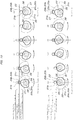
- the rotary cams 29c to 31c of the third rotary drive shaft 22 are rotationally driven from 0 degrees, which is the standby position, to 180 degrees in the normal direction as shown in an explanatory drawing from 0 degrees to 180 degrees of FIG. 10 , thereby respectively switching the outer vertically moving conveyance means 17, the first inner vertically moving conveyance means 19, and the second inner vertically moving conveyance means 20 in the linear conveying device 9 of the diverging device 2 from the upper working position to the lower retracted position as shown in FIG.
- the tray T entering the diverging device 2 from the straight path 1A is transferred onto the arc-shaped drive roller array 10 and the arc-shaped idler roller array 11 of the arc-shaped conveying device 8 continuing from the straight path 1A at the same level without being affected by the linear conveying device 9, and is conveyed on the conveyed object supporting and conveying horizontal plane L1 along the arc-shaped path section 6 without changing the height from the straight path 1A at all.
- the tray T is then sent out onto another conveying path 3 following the arc-shaped path section 6.
- the rotary cams 29c to 31c are stopped in the 180-degree normal rotation completion state at the upper row of FIG. 10 .
- the tray T can be diverged into the arc-shaped path section 6 and sent out onto another conveying path 3 as described above if each rotary cam 29c to 31c is kept in a state of being stopped in the 180-degree phase of FIG. 10 .
- the rotary cams 29c to 31c of the third rotary drive shaft 22 are rotationally driven from the previous 180-degree normal rotation position to a further 180 degrees in the normal direction and returned to the original phase of 0 degrees as shown in an explanatory drawing from 180 degrees to 0 degrees of FIG. 10 , thereby respectively switching the outer vertically moving conveyance means 17, the first inner vertically moving conveyance means 19, and the second inner vertically moving conveyance means 20 in the linear conveying device 9 of the diverging device 2 to the upper working position as shown in FIG.
- the tray T entering the diverging device 2 from the straight path 1A travels straight ahead while slightly rising to around the center of the path length of the linear conveying device 9 by the outer vertically moving conveyance means 17 switched into the upper working position of the outer linear drive conveyor unit 12 and the first inner vertically moving conveyance means 19 switched into the upper working position of the inner linear drive conveyor unit 13 without being affected by the arc-shaped conveying device 8.
- the tray T travels straight ahead while slightly lowering and reaches the terminal end of the constant length straight path section 7 by the outer non-vertically-moving conveyance means 18 of the outer linear drive conveyor unit 12 and the second inner vertically moving conveyance means 20 switched into the upper working position of the inner linear drive conveyor unit 13. Subsequent thereto, the tray T enters the straight path 1A on the downstream side of the diverging device 2 while traveling straight ahead. Since the rotary cams 29c to 31c are stopped in a state of being returned to 0 degrees of FIG. 10 , when the subsequent tray T is to be made to travel straight ahead on the straight path 1A, the tray T is only required to be entered to the diverging device 2 directly without rotationally driving the rotary cams 29c to 31c. When the subsequent tray T is to be diverged into another conveying path 3, the rotary cams 29c to 31c in the 0-degree phase are only required to be normally driven to the 180-degree phase shown in FIG. 10 as described above.
- the diverging device 2 described above is used as the merging device 4 as it is, and the tray conveying direction of the arc-shaped conveying device 8 forming the arc-shaped path section 6 and the tray conveying direction of the linear conveying device 9 forming the constant length straight path section 7 are only required to be changed to the opposite directions.
- the tray T enters the arc-shaped conveying device 8 forming the arc-shaped path section 6 of the merging device 4 from the side connecting to another conveying path 5, and the tray T enters the linear conveying device 9 forming the constant length straight path section 7 from the side opposite to the side where the connection position P of the arc-shaped path section 6 is located. Therefore, as shown in each drawing of FIG. 11 , the effects described above can be obtained in the same way when the rotational drive direction of each rotary cam 29c to 31c by the third rotary drive shaft 22 is changed to the opposite direction. Further, although illustration is omitted in each of the drawings except FIG. 6 and FIG. 7 , a cover plate 16e including openings for making top portions of all of the rollers forming the arc-shaped conveying device 8 and the linear conveying device 9 arranged within the installation frame body 16 upwardly project can be attached to the installation frame body 16.
- outer linear drive conveyor unit 12 of the linear conveying device 9 is replaced with the outer non-vertically-moving conveyance means 18 in the same manner as the inner linear drive conveyor unit 13 to provide a second outer vertically moving conveyance means having a symmetrical structure with the outer vertically moving conveyance means 17.
- the linear conveying device 9 can also be formed of one vertically movable vertically moving conveyance means connected to the end portion on the side, to which the arc-shaped path section 6 is connected, of the constant length straight path section 7.
- the vertically moving conveyance means at the upper working position, which becomes higher than the arc-shaped conveying device 8 connects the straight paths of different heights at both front and rear sides of the constant length straight path section 7.
- the configuration of the present invention can be utilized as a diverging/merging device capable of stably conveying even a tray having a flat and hard bottom surface without causing the tray to flap at a diverging/merging point in conveying equipment in which an arc-shaped path section at an end portion of another conveying path is tangentially connected in the middle of a straight path.
Landscapes
- Engineering & Computer Science (AREA)
- Mechanical Engineering (AREA)
- Branching, Merging, And Special Transfer Between Conveyors (AREA)
- Relays Between Conveyors (AREA)
- Intermediate Stations On Conveyors (AREA)
Abstract
Description
- The present invention relates to a diverging/merging device for conveying equipment in which an arc-shaped path section at an end portion of another conveying path is tangentially connected in the middle of a straight path.
- For a diverging/merging device for conveying equipment of this kind, those having various configurations are known as means for switching conveying paths for conveyed objects as described in, for example,
Patent Literature 1. In general, as described inPatent Literature 1, a configuration has been conceived in which an arc-shaped conveying device (of a roller conveyor type, of a belt conveyor type, etc.) forming the arc-shaped path section and a linear conveying device (of a roller conveyor type, of a belt conveyor type, etc.) forming a constant length straight path section including an entirety of an overlapping area with the arc-shaped path section are configured to be relatively vertically movable and are controlled such that the arc-shaped conveying device is raised to an upper working position and the other linear conveying device is lowered to a lower retracted position when the arc-shaped path section is desired to be used and the linear conveying device is raised to the upper working position and the other arc-shaped conveying device is lowered to the lower retracted position when the linear path section is desired to be used, and the linear conveying device and the arc-shaped conveying device are caused to function alternatively. Further, a configuration is also generally known in which a main conveying path is set to the straight path section and the linear conveying device is fixed at a usable level and only the arc-shaped conveying device forming the arc-shaped path section serving as a secondary conveying path is moved up and down. - Patent Literature 1: Japanese Published Unexamined Patent Application No.
2007-223683 - In any of the configurations, when a conveyed object, for example, a tray loaded with an object, is diverged and conveyed, for example, from the straight path to the arc-shaped path section, the arc-shaped conveying device on the upstream side is in such a state that it is raised with respect to the linear conveying device on the downstream side. As a result, the tray having a hard and flat bottom surface is transferred from the top of the horizontal linear conveying device onto the raised arc-shaped conveying device. Thus, the inclination angle gradually increases as the tray is transferred onto the arc-shaped conveying device, and the tray is finally transferred onto the arc-shaped conveying device in such a manner as to fall with a thud. This phenomenon becomes more noticeable and flapping of the tray also becomes larger as the conveying speed increases, or when the center of the gravity of the tray is closer to the rear due to the loaded object, or as the length of the tray is longer. Such flapping of the tray makes the trajectory at the time the tray is transferred onto the arc-shaped conveying device unstable, and the trajectory of the tray bulges outward to strongly press the tray against an outer arc-shaped guide of the arc-shaped path section, and in some cases, the possibility of diverging failure arises.
- The present invention proposes a diverging/merging device for conveying equipment capable of solving the conventional problem as described above. Described by giving reference signs in parentheses used in the description of an embodiment described below in order to facilitate understanding the relationship with the embodiment, the diverging/merging device for conveying equipment according to the present invention is a diverging/merging device for conveying equipment in which an arc-shaped path section (6) at an end portion of another conveying path (3, 5) is tangentially connected in a middle of a straight path (1A, 1B) and an arc-shaped conveying device (8) forming the arc-shaped path section (6) is fixed at a constant height so that a conveyed object can be conveyed over an entire area of the arc-shaped path section (6) at the same level as the straight path (1A, 1B) tangentially connected with the arc-shaped path section (6), in which the straight path (1A, 1B) includes a constant length straight path section (7) including an entirety of an overlapping area (6a) with the arc-shaped path section (6) from a connection position (P) with the arc-shaped path section (6), and a linear conveying device (9) forming the constant length straight path section (7) includes vertically moving conveyance means (17, 19) tilting in a vertical direction with respect to an end portion of the straight path (1A, 1B) tangentially connected with the arc-shaped path section (6), and when the vertically moving conveyance means (17, 19) are at a lower retracted position of tilting downward, the linear conveying device (9) is located below a conveyed object conveyed by the arc-shaped conveying device (8), and when the vertically moving conveyance means (17, 19) are at an upper working position of tilting upward, a conveyed object conveyed by the linear conveying device (9) passes above the arc-shaped conveying device (8).
- The foregoing configuration of the present invention has the greatest feature in that the straight path is not set as the main conveying path but the arc-shaped path section is set as the main conveying path. The arc-shaped conveying device forming the arc-shaped path section is fixed at a constant height so that the conveyed object can be conveyed over the entire area of the arc-shaped path section at the same level as the straight path tangentially connected with the arc-shaped path section. Thus, described by using a tray having a flat and hard bottom surface as the conveyed object, when the tray is diverged/merged between the straight path and the arc-shaped path section, a situation in which the tray transferred between the straight path and the arc-shaped conveying device is obliquely transferred straddling the straight path and the arc-shaped conveying device as in the conventional case is not caused by simply holding the vertically moving conveyance means of the linear conveying device forming the constant length straight path section at the lower retracted position, even if the conveyed object conveyed by the arc-shaped conveying device is the tray whose bottom surface is hard and flat as described above. As a result, the transfer and change of direction of the tray between the straight path and the arc-shaped conveying device are performed stably without flapping in exactly the same manner as the conveyance of the tray at a normal horizontal curved path section in which two straight paths are connected by an arc-shaped conveying path, and increasing the conveying speed is also facilitated. As a matter of course, the possibility that the tray is strongly pressed against a tray guide on the side of the conveying path or stopped is also eliminated.
- On the other hand, when the tray is made to travel straight ahead on the straight path, the vertically moving conveyance means of the linear conveying device forming the constant length straight path section are switched from the lower retracted position to the upper working position and the tray is made to pass and move in such a manner as to straddle over the arc-shaped conveying device. Since the vertically moving conveyance means which was switched to the upper working position are only connected at an angle with respect to the straight path in side view and the straight path is maintained in plan view, the tray travels straight ahead between the straight path and the vertically moving conveyance means accompanied by inertia in the straight-ahead direction even if a situation in which the tray is obliquely supported between the straight path and the vertically moving conveyance means occurs. There is no possibility that variations occur in the moving direction of the tray and the tray is unduly pressed against the tray guide on the side of the conveying path or stopped. Since the vertically moving conveyance means are only required to be provided to the linear conveying device side, the configuration of the entire device is simplified and can be implemented inexpensively as compared with a configuration that the vertically moving conveyance means are provided to both the arc-shaped conveying device and the linear conveying device and the both need to be moved upward and downward reversibly.
- When the foregoing present invention is implemented, the linear conveying device (9) can be structured to include first vertically moving conveyance means (17, 19) tilting in the vertical direction with respect to one end of the constant length straight path section (7) and a second vertically moving conveyance means (20) tilting in the vertical direction with respect to the other end of the constant length straight path section (7), and when both the first and second vertically moving conveyance means (17, 19, 20) are at the upper working position, a conveying surface on the linear conveying device (9) can be configured to be deformed in a mountain shape in which an intermediate part is raised. According to this configuration, there is no need to make a difference in level in conveying path height before and after the constant length straight path section as in the case where the constant length straight path section is formed of only one vertically moving conveyance means in side view, and it becomes possible to incorporate the diverging/merging device into an existing straight path.
- Further, the linear conveying device (9) can be formed of an outer linear drive conveyor unit (12) on a side farther from an arc center of the arc-shaped path section (6) and an inner linear drive conveyor unit (13) on a side closer to the arc center, and the arc-shaped conveying device (8) can be formed of an arc-shaped drive roller array (10) on a side farther from the arc center and an arc-shaped idler roller array (11) on a side closer to the arc center. The arc-shaped drive roller array (10) can have its one end arranged at a position adjacent, on a side where the arc center is located, to one end of the outer linear drive conveyor unit (12) and have its intermediate portion arranged so as to cross an intermediate position of the inner linear drive conveyor unit (13). The arc-shaped idler roller array (11) can have its one end arranged at a position adjacent, on a side where the arc center is located, to one end of the inner linear drive conveyor unit (13). The outer linear drive conveyor unit (12) can be formed of an outer vertically moving conveyance means (17) forming the area (6a) overlapping with the arc-shaped path section (6) and an outer non-vertically-moving conveyance means (18) forming an outside of the area (6a). The outer non-vertically-moving conveyance means (18) can be fixed at a height such that the outer non-vertically-moving conveyance means (18) is connected to the outer vertically moving conveyance means (17) when at the upper working position. The inner linear drive conveyor unit (13) can have its entire length formed of an inner vertically moving conveyance means (19, 20).
- According to this configuration, similar to the inner linear drive conveyor unit, the structure is simplified and can be implemented inexpensively as compared with the case in which the entire length of the outer linear drive conveyor unit of the linear conveying device is formed of the vertically moving conveyance means. Further, the arc-shaped drive roller array of the arc-shaped conveying device is located while biased toward a side closer to an arc-shaped center line of the arc-shaped conveying path section, so that the degree of reduction in the conveying speed of the tray conveyed along the arc-shaped conveying path section can be suppressed.
- At the connection position (P), conveyed object support levels of the straight path (1A, 1B) and the arc-shaped conveying device (8) and the linear conveying device (9) can be configured to be the same. The outer vertically moving conveyance means (17) can have one end on the connection position (P) side pivotally supported so as to be vertically movable and the other end supported by a support height changeable first support means (29). The inner vertically moving conveyance means (19, 20) can have its entire length divided into two parts and be formed of a first inner vertically moving conveyance means (19) on the connection position (P) side and a second inner vertically moving conveyance means (20) on the opposite side, and the first inner vertically moving conveyance means (19) and the second inner vertically moving conveyance means (20) can have respective inner end portions adjacent to each other supported by a support height changeable second support means (30) and third support means (31) and have respective outer end portions on the opposite side pivotally supported so as to be vertically movable. Specifically, the first support means (29), the second support means (30), and the third support means (31) can be respectively composed of rotary cams (29c to 31c) attached to one common drive shaft (22) and cam follower rollers (29b to 31b) respectively supported by the rotary cams (29c to 31c).
- Furthermore, to one end on the connection position (P) side of the constant length straight path section (7), a first driving rotary shaft (21) can be supported along a path transverse direction, and to the other end on a side opposite to the connection position (P) side of the constant length straight path section (7), a second driving rotary shaft (23) can be supported in the path transverse direction. The outer vertically moving conveyance means (17) and the first inner vertically moving conveyance means (19) can be supported by the first driving rotary shaft (21) so as to be vertically movable, and the second inner vertically moving conveyance means (20) can be supported by the second driving rotary shaft (23) so as to be vertically movable. Drive rollers (17a) forming the outer vertically moving conveyance means (17), drive rollers (19a) forming the first inner vertically moving conveyance means (19), and drive rollers (10a) of the arc-shaped drive roller array (10) can be interlockingly coupled to the first driving rotary shaft (21), and drive rollers (18a) forming the outer non-vertically-moving conveyance means (18) and drive rollers (20a) forming the second inner vertically moving conveyance means (20) can be interlockingly coupled to the second driving rotary shaft (23). According to this configuration, the driving rotary shafts for driving the respective drive rollers can also be used as support shafts pivotally supporting one end portions of respective vertically moving conveyance means, and the number of parts can be reduced.
- When the foregoing configuration is adopted, the drive rollers (20a) forming the second inner vertically moving conveyance means (20) can be provided only outside the arc-shaped drive roller array (10), and idler rollers (20c) can be provided at an area inner than the arc-shaped drive roller array (10) of the second inner vertically moving conveyance means (20). With this configuration, the configuration of the second inner vertically moving conveyance means can be simplified to reduce the cost.
- Furthermore, one end drive roller (19a) forming a drive roller array of the first inner vertically moving conveyance means (19) and one end drive roller (10a) forming the arc-shaped drive roller array (10) can be attached to the first driving rotary shaft (21), and the drive roller (17a) at one end on the connection position (P) side of a drive roller array of the outer vertically moving conveyance means (17) and an idler roller (11b) at one end on the connection position (P) side of the arc-shaped idler roller array (11) can be separated from the first driving rotary shaft. According to this configuration, the function of the idler roller to be arranged at one end on the connection position side of the arc-shaped idler roller array can be supplemented by the one end drive roller forming the drive roller array of the first inner vertically moving conveyance means, and the function of the drive roller to be arranged at one end of the connection position side of the drive roller array of the outer vertically moving conveyance means can be supplemented by the one end drive roller forming the arc-shaped drive roller array, so that the number of parts can be reduced to reduce the cost.
-
- [
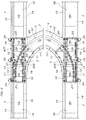
FIG. 1] FIG. 1 is a schematic plan view explaining a layout of conveying equipment in which a diverging device and a merging device are combined. - [
FIG. 2] FIG. 2 is a plan view showing a specific structure of the diverging device and the merging device ofFIG. 1 . - [
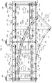
FIG. 3] FIG. 3 is an enlarged detailed plan view of the diverging device ofFIG. 1 . - [
FIG. 4] FIG. 4 is a side view ofFIG. 3 . - [
FIG. 5] FIG. 5 is a longitudinal sectional side view explaining an outer linear drive conveyor unit ofFIG. 3 . - [
FIG. 6] FIG. 6 is a central cross-sectional front view ofFIG. 3 , showing a state when a tray is made to travel straight ahead along a straight path. - [
FIG. 7] FIG. 7 is a central cross-sectional front view ofFIG. 3 , showing a state when the tray is made to travel straight ahead along an arc-shaped path section. - [
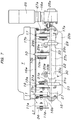
FIG. 8] FIG. 8 is a longitudinal sectional side view explaining an inner linear drive conveyor unit switched to an upper working position and support height changeable support means. - [
FIG. 9] FIG. 9 is a longitudinal sectional side view explaining the inner linear drive conveyor unit switched to a lower retracted position and the support height changeable support means. - [
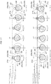
FIG. 10] FIG. 10 is a side view explaining the working state of each stage of the support height changeable support means used in the diverging device. - [
FIG. 11] FIG. 11 is a side view explaining the working state of each stage of the support height changeable support means used in the merging device. - In
FIG. 1 andFIG. 2 ,reference signs straight path 1A, anotherconveying path 3 is diverged and connected from the middle of thestraight path 1A via adiverging device 2. To thestraight path 1B, anotherconveying path 5 is merged and connected in the middle of thestraight path 1B via amerging device 4. The divergingdevice 2 and the mergingdevice 4 have the same structure except that the conveying direction of the conveyed object is reverse, and include an arc-shapedpath section 6 and a constant lengthstraight path section 7. The arc-shapedpath section 6 is connected to a connection end portion with thestraight path path straight path device 8. The constant lengthstraight path section 7 is a part of thestraight path area 6a with the arc-shapedpath section 6 from a connection position P between thestraight path path section 6, and includes a linear conveyingdevice 9. - The arc-shaped conveying
device 8 is formed of an arc-shapeddrive roller array 10 on a side farther from the arc center of the arc-shapedpath section 6 and an arc-shapedidler roller array 11 on a side closer to the arc center. The linear conveyingdevice 9 is formed of an outer lineardrive conveyor unit 12 on a side farther from the arc center of the arc-shapedpath section 6 and an inner lineardrive conveyor unit 13 on a side closer to the arc center. An outerdrive conveyor unit 14 and an innerdrive conveyor unit 15 are arranged side by side bilaterally symmetrically at thestraight paths device 2 and the mergingdevice 4. The outer lineardrive conveyor unit 12 of the linear conveyingdevice 9 is arranged at a position linearly connecting to the outerdrive conveyor unit 14 of thestraight path drive conveyor unit 12. The inner lineardrive conveyor unit 13 of the linear conveyingdevice 9 is arranged at a position closer to an inner side (a side where the outer lineardrive conveyor unit 12 is located) than a position linearly connecting to the innerdrive conveyor unit 15 of thestraight path drive conveyor unit 13. - The arc-shaped
drive roller array 10 of the arc-shaped conveyingdevice 8 has one end arranged at a position adjacent, on the side where the arc center is located, to one end of the outer lineardrive conveyor unit 12 and has an intermediate portion arranged so as to cross an intermediate position of the inner lineardrive conveyor unit 13. The arc-shapedidler roller array 11 has one end arranged at a position adjacent, on the side where the arc center is located, to one end of the inner lineardrive conveyor unit 13. The conveyingpath path section path section 6 of the divergingdevice 2 or the mergingdevice 4. The arc-shapedpath section drive roller array 10 of the arc-shaped conveyingdevice 8 provided to the arc-shapedpath section 6 and an arc-shaped idler roller array 11' connected to the arc-shapedidler roller array 11 of the arc-shaped conveyingdevice 8. However, the arc-shapedpath section path straight path drive conveyor unit 14 and the innerdrive conveyor unit 15. - The detailed structure of the diverging
device 2 will be described based onFIG. 3 to FIG. 9 . The divergingdevice 2 is incorporated into aninstallation frame body 16 having a rectangular shape in plan view, inside of which the outer lineardrive conveyor unit 12 and the inner lineardrive conveyor unit 13 of the linear conveyingdevice 9 are arranged side by side. The outer lineardrive conveyor unit 12 has its entire length divided into two parts and is composed of an outer vertically moving conveyance means 17 of the front half on the connection position P side and an outer non-vertically-moving conveyance means 18 of the rear half. The inner lineardrive conveyor unit 13 has its entire length divided into two parts and is composed of a first inner vertically moving conveyance means 19 of the front half on the connection position P side and a second inner vertically moving conveyance means 20 of the rear half. A firstrotary drive shaft 21 and a secondrotary drive shaft 23 are supported by an end portion on the connection position P side and an end portion opposite thereto of theinstallation frame body 16, and a thirdrotary drive shaft 22 is supported by a central portion in the length direction of theinstallation frame body 16. Each of therotary drive shafts 21 to 23 is supported in an orientation of traversing the conveying path, and to an end portion on a side opposite to a side where the arc-shapedpath section 6 is located, an output shaft of each of drivingmotors 24 to 26 is directly connected outside theinstallation frame body 16. Each of the drivingmotors 24 to 26 is coupled to theinstallation frame body 16 by acoupling member 24a to 26a in order to prevent the motor itself from rotating around therotary drive shafts 21 to 23. - To the first
rotary drive shaft 21, one end of amovable frame 27 is vertically movably supported with the firstrotary drive shaft 21 as a supporting point. To the secondrotary drive shaft 23, one end of amovable frame 28 is vertically movably supported with the secondrotary drive shaft 23 as a supporting point. Themovable frame 27 extends from the firstrotary drive shaft 21 toward the central thirdrotary drive shaft 22 and is composed of a pair of left and right side frames 27a, 27b and acoupling frame 27c coupling and integrating free end portions of bothside frames outer side frame 27a, the outer vertically moving conveyance means 17 is attached, and inside theinner side frame 27b, the first inner vertically moving conveyance means 19 is attached. The outer vertically moving conveyance means 17 is composed ofdrive rollers 17a pivotally supported inside theside frame 27a at regular intervals andtransmission belts 17b interlockingly couplingadjacent drive rollers 17a together using double pulleys consecutively provided concentrically and integrally torespective drive rollers 17a. Thedrive roller 17a on the firstrotary drive shaft 21 side is separated from the firstrotary drive shaft 21 by about one pitch between thedrive rollers 17a. Thus, thedrive roller 17a adjacent to the firstrotary drive shaft 21 is interlockingly coupled to the firstrotary drive shaft 21 by an additional belt transmission means 17c. Therefore, all of thedrive rollers 17a of the outer vertically moving conveyance means 17 are interlockingly driven by the rotation of the firstrotary drive shaft 21. - The first inner vertically moving conveyance means 19 is composed of
drive rollers 19a pivotally supported inside theside frame 27b at regular intervals so as to form a left/right pair with thedrive rollers 17a andtransmission belts 19b interlockingly couplingadjacent drive rollers 19a together using double pulleys consecutively provided concentrically and integrally torespective drive rollers 19a. Thedrive roller 19a is also attached to the firstrotary drive shaft 21. Therefore, all of thedrive rollers 19a of the first inner vertically moving conveyance means 19 are interlockingly driven by the rotation of the firstrotary drive shaft 21. - So as to be arranged in series with the outer vertically moving conveyance means 17 in a straight line, the outer non-vertically-moving conveyance means 18 is composed of
drive rollers 18a pivotally supported inside theinstallation frame body 16 at regular intervals andtransmission belts 18b interlockingly couplingadjacent driver rollers 18a together using double pulleys consecutively provided concentrically and integrally torespective drive rollers 18a. Thedrive roller 18a at an end on the secondrotary drive shaft 23 side is also attached to the secondrotary drive shaft 23. Thus, all of thedrive rollers 18a of the outer non-vertically-moving conveyance means 18 are interlockingly driven by the rotation of the secondrotary drive shaft 23. - The second inner vertically moving conveyance means 20 is composed of a
drive roller array 20A and anidler roller array 20B attached to themovable frame 28 extending from the secondrotary drive shaft 23 toward the central thirdrotary drive shaft 22. Thedrive roller array 20A is arranged at a rear half area from an area crossing the arc-shapeddrive roller array 10 of the arc-shaped conveyingdevice 8 to the secondrotary drive shaft 23. Thedrive roller array 20A is composed ofdrive rollers 20a arranged at regular intervals so as to form a left/right pair with thedrive rollers 18a of the outer non-vertically-moving conveyance means 18 andtransmission belts 20b interlockingly couplingadjacent drive rollers 20a together using double pulleys consecutively provided concentrically and integrally torespective drive rollers 20a. Thedrive roller 20a is also attached to the secondrotary drive shaft 23 in the same manner as the outer non-vertically-moving conveyance means 18, and all of thedrive rollers 20a (twodrive rollers 20a in the illustrated example) in thedrive roller array 20A are interlockingly driven by the rotation of the secondrotary drive shaft 23. Theidler roller array 20B is formed ofidler rollers 20c (twoidler rollers 20c in the illustrated example) pivotally supported, at regular intervals, by themovable frame 28 from the area crossing the arc-shapeddrive roller array 10 of the arc-shaped conveyingdevice 8 to a free end on the thirdrotary drive shaft 22 side so as to form a left/right pair with thedrive rollers 18a of the outer non-vertically-moving conveyance means 18. - To the outer vertically moving conveyance means 17, the first inner vertically moving conveyance means 19, and the second inner vertically moving conveyance means 20, a support height changeable first support means 29, second support means 30, and third support means 31 switching the height of the conveying means between a lower retracted position and an upper working position are juxtaposed. The first support means 29 and the second support means 30 are formed of
arms movable frame 27 supporting the outer vertically moving conveyance means 17 and the first inner vertically moving conveyance means 19 so as to extend toward the upper side of the thirdrotary drive shaft 22,cam follower rollers arms rotary cams rotary drive shaft 22 so as to support both thecam follower rollers arm 31a arranged at a free end (an end portion on a side adjacent to the central third rotary drive shaft 22) of themovable frame 28 supporting the second inner vertically moving conveyance means 20 so as to extend toward the upper side of the thirdrotary drive shaft 22, acam follower roller 31b pivotally supported by a free end of thearm 31a, and arotary cam 31c attached to the thirdrotary drive shaft 22 so as to support thecam follower roller 31b. - The arc-shaped
drive roller array 10 of the arc-shaped conveyingdevice 8 is composed of an outer arc-shapedside frame 33 supported at a constant height by a plurality ofsupport frames 32a to 32d disposed so as to connect lower sides of both left and right side frames 16a, 16b of theinstallation frame body 16,drive rollers 10a pivotally supported by the outer arc-shapedside frame 33 at regular intervals, andtransmission belts 10b interlockingly couplingadjacent drive rollers 10a together using double pulleys consecutively provided concentrically and integrally torespective drive rollers 10a. The outer arc-shapedside frame 33 has an end on the firstrotary drive shaft 21 side separated from the firstrotary drive shaft 21. Therefore, thedrive roller 10a arranged at the end on the firstrotary drive shaft 21 side of the arc-shapeddrive roller array 10 is attached to the firstrotary drive shaft 21. Thus, all of thedrive rollers 10a of the arc-shapeddrive roller array 10 are interlockingly driven by the rotation of the firstrotary drive shaft 21. - Since the arc-shaped
drive roller array 10 crosses the second inner vertically moving conveyance means 20 of the linear conveyingdevice 9 and theinner side frame 16b of theinstallation frame body 16, notchedportions movable frame 28 supporting the second inner vertically moving conveyance means 20 interferes with the arc-shapeddrive roller array 10 at the time of moving up and down and swinging and a place where theinner side frame 16b of theinstallation frame body 16 interferes with the arc-shapeddrive roller array 10. Thecoupling frame 27c of themovable frame 27 and the thirdrotary drive shaft 22 crossing the arc-shapeddrive roller array 10 in plan view are provided lower than the arc-shapeddrive roller array 10, so that they do not interfere with each other. - The arc-shaped
idler roller array 11 of the arc-shaped conveyingdevice 8 is formed ofidler rollers 11a pivotally supported, at appropriate intervals, by an inner arc-shapedside frame 34 concentric with the outer arc-shapedside frame 33 forming the arc-shapeddrive roller array 10 and anidler roller 11b pivotally supported by theinner side frame 16b of theinstallation frame body 16. The inner arc-shapedside frame 34 is such that an inner end portion inserted inside theinner side frame 16b of theinstallation frame body 16 from a notchedportion 16d provided to theside frame 16b is fixed inside theside frame 16b and an outer end portion extending outside theside frame 16b from the notchedportion 16d is coupled to an outer end portion of the outer arc-shapedside frame 33 by acoupling member 35 and is attached to thesupport frame 32c. Theidler roller 11b pivotally supported by theinner side frame 16b of theinstallation frame body 16 is located at a position almost concentric with thedrive roller 10a pivotally supported by the end on the firstrotary drive shaft 21 side of the outer arc-shapedside frame 33 of the arc-shapeddrive roller array 10. All of thedrive rollers 10a and all of theidler rollers device 8 are in contact with a horizontal plane L1 (seeFIG. 4 ) of a constant height together with thedrive roller 19a attached to the firstrotary drive shaft 21 of the first inner vertically moving conveyance means 19 in the linear conveyingdevice 9. - On the other hand, the
drive rollers rotary drive shaft 21 and the secondrotary drive shaft 23 located at both ends of the constant lengthstraight path section 7, that is, a total of four drive rollers of thedrive roller 10a attached to the firstrotary drive shaft 21 of thedrive rollers 10a of the arc-shapeddrive roller array 10, thedrive roller 19a attached to the firstrotary drive shaft 21 of thedrive rollers 19a of the first inner vertically moving conveyance means 19, thedrive roller 18a attached to the secondrotary drive shaft 23 of thedrive rollers 18a of the outer non-vertically-moving conveyance means 18, and thedrive roller 20a attached to the secondrotary drive shaft 23 of thedrive rollers 20a of the second inner vertically moving conveyance means 20 are in contact with the horizontal plane L1 of the constant height, which is a conveyed object supporting and conveying surface in the arc-shapedpath section 6. - The
rotary cams diameter arc portion 36 extending over approximately 180 degrees and a largediameter arc portion 37 connected to the smalldiameter arc portion 36 via rising/lowering gradient portions at both ends in the remaining area extending over approximately 180 degrees, and are attached to the thirdrotary drive shaft 22 in the same phase. Therotary cam 31c of the third support means 31 includes a smalldiameter arc portion 38 extending over approximately 180 degrees, which is the same as the smalldiameter arc portions 36 of therotary cams diameter arc portion 39 having a larger diameter than the largediameter arc portions 37 and connected to the smalldiameter arc portion 38 via rising/lowering gradient portions at both ends in the remaining area extending over approximately 180 degrees. Therotary cam 31c is attached to the thirdrotary drive shaft 22 in a phase where the vicinities of terminal end portions of the largediameter arc portions 37 in therotary cams diameter arc portion 39 in therotary cam 31c coincide. In the divergingdevice 2, therotary cams 29c to 31c on the thirdrotary drive shaft 22 shown inFIG. 8 to FIG. 10 are rotationally driven in a counterclockwise direction. - As shown in
FIG. 8 , when the vicinities of the terminal ends of the largediameter arc portions 37 of therotary cams cam follower rollers diameter arc portion 39 of therotary cam 31c of the third support means 31 supports thecam follower roller 31b, the free end side of themovable frames 27 is raised to the rising limit height via thearms movable frame 28 is raised to the rising limit height via thearm 31a. As a result, the outer vertically moving conveyance means 17 in the outer lineardrive conveyor unit 12, the first inner vertically moving conveyance means 19 in the inner lineardrive conveyor unit 13, and the second inner vertically moving conveyance means 20 in the inner lineardrive conveyor unit 13 of the linear conveyingdevice 9 are moved upward with the firstrotary drive shaft 21 and the secondrotary drive shaft 23 as supporting points and switched to the upper working position, and the free end portions (the inner end portions) are raised to the rising limit height. The phase of therotary cams 29c to 31c at this time is shown as 0 degrees inFIG. 10 . - When the phase of the
rotary cams 29c to 31c is at 0 degrees ofFIG. 10 as described above, as shown inFIG. 8 , a conveyed object supporting and conveying surface L2 of the inner lineardrive conveyor unit 13 is bent and deformed in a mountain shape in such a manner that a central portion of the conveying path of the inner lineardrive conveyor unit 13 is slightly higher than the conveyed object supporting and conveying horizontal plane L1 of the constant height in the arc-shapedpath section 6. The outer vertically moving conveyance means 17 in the outer lineardrive conveyor unit 12 of the linear conveyingdevice 9 is moved upward with the firstrotary drive shaft 21 as the supporting point to the same inclination angle as the first inner vertically moving conveyance means 19 in the inner lineardrive conveyor unit 13, is switched into the upper working position, and becomes the same as an upward sloping path section of the front half of the conveyed object supporting and conveying surface L2. As shown inFIG. 1 andFIG. 3 , the outer non-vertically-moving conveyance means 18 in the outer lineardrive conveyor unit 12 of the linear conveyingdevice 9 is off the arc-shapedpath section 6 to the outside. Thus, the entire area of the outer non-vertically-moving conveyance means 18 may be configured in a downward gradient shape that inclines at the same angle as the downward gradient second inner vertically moving conveyance means 20 whose inner end side is raised by the third support means 31 as described above. However, in the present embodiment, as shown inFIG. 5 , the front half portion on the inner end side is set at the same level as the conveyed object supporting and conveying horizontal plane L1 of the constant height in the arc-shapedpath section 6, and the rear half portion is configured to be a slightly rising gradient to the same level as thedrive roller 18a on the secondrotary drive shaft 23. - Further, in a state in which each
rotary cam 29c to 31c is normally rotated 180 degrees from the phase shown in 0 degrees ofFIG. 10 , as shown inFIG. 9 , the vicinities of terminal ends of the smalldiameter arc portions 36 of therotary cams cam follower rollers diameter arc portion 38 of therotary cam 31c of the third support means 31 supports thecam follower roller 31b. As a result, the free end side of themovable frame 27 is lowered to the lowering limit height via thearms movable frame 28 is lowered to the lowering limit height via thearm 31a. Accordingly, the first inner vertically moving conveyance means 19 and the second inner vertically moving conveyance means 20 in the inner lineardrive conveyor unit 13 and the outer vertically moving conveyance means 17 in the outer lineardrive conveyor unit 12 of the linear conveyingdevice 9 are moved downward with the firstrotary drive shaft 21 as the supporting point, switched into the lower retracted position, and deformed in such a manner as to be bent in a valley shape opposite to the inclined state shown inFIG. 8 . At this time, thedrive rollers 17a of the outer vertically moving conveyance means 17 in the outer lineardrive conveyor unit 12 at least located at the area overlapping with the arc-shapedpath section 6, thedrive rollers 19a of the first inner vertically moving conveyance means 19 in the inner lineardrive conveyor unit 13, and theidler rollers 20c and thedrive rollers 20a of the second inner vertically moving conveyance means 20 become lower than the conveyed object supporting and conveying horizontal plane L1 of the constant height in the arc-shapedpath section 6. Of thedrive rollers 19a at the area overlapping with the arc-shapedpath section 6, thedrive roller 19a attached to the firstrotary drive shaft 21 is located at the same level as the conveyed object supporting and conveying horizontal plane L1 of the constant height in the arc-shapedpath section 6. - The operation of the diverging
device 2 configured as described above will be described. Herein, a tray T molded from a hard material, having a rectangular shape, and loaded with an object is used as the conveyed object to be conveyed. The description is given assuming that eachrotary cam 29c to 31c is in the phase shown in 0 degrees ofFIG. 10 , and the outer vertically moving conveyance means 17, the first inner vertically moving conveyance means 19, and the second inner vertically moving conveyance means 20 in the linear conveyingdevice 9 are in a state of being at the upper working position as shown inFIG. 8 , that is, a state in which the tray T is made to travel straight ahead by the linear conveying device 9 (a state in which the arc-shaped conveyingdevice 8 is not working). - The tray T is conveyed toward the diverging
device 2 by the outerdrive conveyor unit 14 and the innerdrive conveyor unit 15 of thestraight path 1A. When the tray T is to be diverged from thestraight path 1A to another conveyingpath 3, according to this information, therotary cams 29c to 31c of the thirdrotary drive shaft 22 are rotationally driven from 0 degrees, which is the standby position, to 180 degrees in the normal direction as shown in an explanatory drawing from 0 degrees to 180 degrees ofFIG. 10 , thereby respectively switching the outer vertically moving conveyance means 17, the first inner vertically moving conveyance means 19, and the second inner vertically moving conveyance means 20 in the linear conveyingdevice 9 of the divergingdevice 2 from the upper working position to the lower retracted position as shown inFIG. 9 and deforming the conveyed object supporting and conveying surface of the linear conveyingdevice 9 in the valley shape in which the central portion becomes lower than the conveyed object supporting and conveying horizontal plane L1 of the arc-shapedpath section 6. As a result, the tray T entering the divergingdevice 2 from thestraight path 1A is transferred onto the arc-shapeddrive roller array 10 and the arc-shapedidler roller array 11 of the arc-shaped conveyingdevice 8 continuing from thestraight path 1A at the same level without being affected by the linear conveyingdevice 9, and is conveyed on the conveyed object supporting and conveying horizontal plane L1 along the arc-shapedpath section 6 without changing the height from thestraight path 1A at all. The tray T is then sent out onto another conveyingpath 3 following the arc-shapedpath section 6. Therotary cams 29c to 31c are stopped in the 180-degree normal rotation completion state at the upper row ofFIG. 10 . When the subsequent tray T is to be diverged onto another conveyingpath 3, the tray T can be diverged into the arc-shapedpath section 6 and sent out onto another conveyingpath 3 as described above if eachrotary cam 29c to 31c is kept in a state of being stopped in the 180-degree phase ofFIG. 10 . - When the tray T being conveyed on the
straight path 1A toward the divergingdevice 2 is not to be diverged into another conveyingpath 3 but to be made to travel straight ahead on thestraight path 1A as it is, according to this information, therotary cams 29c to 31c of the thirdrotary drive shaft 22 are rotationally driven from the previous 180-degree normal rotation position to a further 180 degrees in the normal direction and returned to the original phase of 0 degrees as shown in an explanatory drawing from 180 degrees to 0 degrees ofFIG. 10 , thereby respectively switching the outer vertically moving conveyance means 17, the first inner vertically moving conveyance means 19, and the second inner vertically moving conveyance means 20 in the linear conveyingdevice 9 of the divergingdevice 2 to the upper working position as shown inFIG. 8 and deforming the conveyed object supporting and conveying surface L2 of the linear conveyingdevice 9 in the mountain shape in which the central portion is higher than the conveyed object supporting and conveying horizontal plane L1 of the arc-shapedpath section 6. As a result, the tray T entering the divergingdevice 2 from thestraight path 1A travels straight ahead while slightly rising to around the center of the path length of the linear conveyingdevice 9 by the outer vertically moving conveyance means 17 switched into the upper working position of the outer lineardrive conveyor unit 12 and the first inner vertically moving conveyance means 19 switched into the upper working position of the inner lineardrive conveyor unit 13 without being affected by the arc-shaped conveyingdevice 8. After that, the tray T travels straight ahead while slightly lowering and reaches the terminal end of the constant lengthstraight path section 7 by the outer non-vertically-moving conveyance means 18 of the outer lineardrive conveyor unit 12 and the second inner vertically moving conveyance means 20 switched into the upper working position of the inner lineardrive conveyor unit 13. Subsequent thereto, the tray T enters thestraight path 1A on the downstream side of the divergingdevice 2 while traveling straight ahead. Since therotary cams 29c to 31c are stopped in a state of being returned to 0 degrees ofFIG. 10 , when the subsequent tray T is to be made to travel straight ahead on thestraight path 1A, the tray T is only required to be entered to the divergingdevice 2 directly without rotationally driving therotary cams 29c to 31c. When the subsequent tray T is to be diverged into another conveyingpath 3, therotary cams 29c to 31c in the 0-degree phase are only required to be normally driven to the 180-degree phase shown inFIG. 10 as described above. - As shown in the explanatory drawing from 0 degrees to 180 degrees at the upper row of
FIG. 10 , when therotary cams 29c to 31c are rotationally driven from 0 degrees to 180 degrees in the normal direction to respectively switch the outer vertically moving conveyance means 17, the first inner vertically moving conveyance means 19, and the second inner vertically moving conveyance means 20 from the upper working position to the lower retracted position, the second inner vertically moving conveyance means 20 on the downstream side is switched from the upper working position to the lower retracted position at a final stage of reaching 180 degrees from 165 degrees, whereas the outer vertically moving conveyance means 17 and the first inner vertically moving conveyance means 19 on the upstream side are switched from the upper working position to the lower retracted position at an initial stage of reaching 65 degrees from 15 degrees. This is to avoid an accident that the tray T entering the divergingdevice 2 comes into contact with the outer vertically moving conveyance means 17 and the first inner vertically moving conveyance means 19 before being completely switched to the lower retracted position, by switching the outer vertically moving conveyance means 17 and the first inner vertically moving conveyance means 19 at the entrance side of the divergingdevice 2 into the lower retracted position in advance of the second inner vertically moving conveyance means 20 at the exit side of the divergingdevice 2. - As shown in the explanatory drawing from 180 degrees to 0 degrees at the lower row of
FIG. 10 , when therotary cams 29c to 31c are rotationally driven from the 180-degree normal rotation position to a further 180 degrees in the normal direction to respectively switch the outer vertically moving conveyance means 17, the first inner vertically moving conveyance means 19, and the second inner vertically moving conveyance means 20 from the lower retracted position to the upper working position, the second inner vertically moving conveyance means 20 on the downstream side is switched from the lower retracted position to the upper working position at a final stage of reaching 345 degrees from 295 degrees, whereas the outer vertically moving conveyance means 17 and first inner vertically moving conveyance means 19 on the upstream side are switched from the lower retracted position to the upper working position at an initial stage of reaching 245 degrees from 195 degrees. This is to avoid an accident caused by the fact that the switching of the outer vertically moving conveyance means 17 and the first inner vertically moving conveyance means 19 to the upper working position is delayed and the tray T entering the divergingdevice 2 enters on the arc-shaped conveyingdevice 8 and receives a thrust in a direction along the arc-shapedpath section 6, by switching the outer vertically moving conveyance means 17 and the first inner vertically moving conveyance means 19 at the entrance side of the divergingdevice 2 to the upper working position in advance of the second inner vertically moving conveyance means 20 at the exit side of the divergingdevice 2. - As shown in
FIG. 1 andFIG. 2 , when the configuration of the present invention is applied to the mergingdevice 4, the divergingdevice 2 described above is used as the mergingdevice 4 as it is, and the tray conveying direction of the arc-shaped conveyingdevice 8 forming the arc-shapedpath section 6 and the tray conveying direction of the linear conveyingdevice 9 forming the constant lengthstraight path section 7 are only required to be changed to the opposite directions. In this case, the tray T enters the arc-shaped conveyingdevice 8 forming the arc-shapedpath section 6 of the mergingdevice 4 from the side connecting to another conveyingpath 5, and the tray T enters the linear conveyingdevice 9 forming the constant lengthstraight path section 7 from the side opposite to the side where the connection position P of the arc-shapedpath section 6 is located. Therefore, as shown in each drawing ofFIG. 11 , the effects described above can be obtained in the same way when the rotational drive direction of eachrotary cam 29c to 31c by the thirdrotary drive shaft 22 is changed to the opposite direction. Further, although illustration is omitted in each of the drawings exceptFIG. 6 andFIG. 7 , acover plate 16e including openings for making top portions of all of the rollers forming the arc-shaped conveyingdevice 8 and the linear conveyingdevice 9 arranged within theinstallation frame body 16 upwardly project can be attached to theinstallation frame body 16. - The preferred embodiment of the present invention has been described above. Basically, it is also possible that the outer linear
drive conveyor unit 12 of the linear conveyingdevice 9 is replaced with the outer non-vertically-moving conveyance means 18 in the same manner as the inner lineardrive conveyor unit 13 to provide a second outer vertically moving conveyance means having a symmetrical structure with the outer vertically moving conveyance means 17. Further, if, with respect to the straight path connected to the end portion on the side, to which the arc-shapedpath section 6 is connected, of the constant lengthstraight path section 7, the straight path connected to the other end side can be made higher, the linear conveyingdevice 9 can also be formed of one vertically movable vertically moving conveyance means connected to the end portion on the side, to which the arc-shapedpath section 6 is connected, of the constant lengthstraight path section 7. In this case, the vertically moving conveyance means at the upper working position, which becomes higher than the arc-shaped conveyingdevice 8, connects the straight paths of different heights at both front and rear sides of the constant lengthstraight path section 7. - The configuration of the present invention can be utilized as a diverging/merging device capable of stably conveying even a tray having a flat and hard bottom surface without causing the tray to flap at a diverging/merging point in conveying equipment in which an arc-shaped path section at an end portion of another conveying path is tangentially connected in the middle of a straight path.
-
- 1A, 1B Straight path
- 2 Diverging device
- 3, 5 Another conveying path
- 4 Merging device
- 6 Arc-shaped path section
- 7 Constant length straight path section
- 8 Arc-shaped conveying device
- 9 Linear conveying device
- 10, 10' Arc-shaped drive roller array
- 10a, 17a, 18a, 19a, 20a Drive roller
- 10b, 17b, 18b, 19b, 20b Transmission belt
- 11, 11' Arc-shaped idler roller array
- 11a, 11b Idler roller
- 12 Outer linear drive conveyor unit
- 13 Inner linear drive conveyor unit
- 14 Outer drive conveyor unit of
straight path - 15 Inner drive conveyor unit of
straight path - 16 Installation frame body
- 16a, 16b Both left and right side frames
- 16c, 16d, 28a Notched portion
- 17 Outer vertically moving conveyance means
- 17c Belt transmission means
- 18 Outer non-vertically-moving conveyance means
- 19 First inner vertically moving conveyance means
- 20 Second inner vertically moving conveyance means
- 20A Drive roller array
- 20B Idler roller array
- 21 First rotary drive shaft
- 22 Third rotary drive shaft
- 23 Second rotary drive shaft
- 24 to 26 Driving motor
- 27, 28 Movable frame
- 29 First support means
- 29a to 31a Arm
- 29b to 31b Cam follower roller
- 29c to 31c Rotary cam
- 30 Second support means
- 31 Third support means
- 32a to 32d support frame
- 33 Outer arc-shaped side frame
- 34 Inner arc-shaped side frame
- 35 Coupling member
- 36, 38 Small diameter arc portion
- 37, 39 Large diameter arc portion
- L1 Conveyed object supporting and conveying horizontal plane of constant height in arc-shaped path section
- L2 Conveyed object supporting and conveying surface of inner linear drive conveyor unit
Claims (8)
- A diverging/merging device for conveying equipment in which an arc-shaped path section at an end portion of another conveying path is tangentially connected in a middle of a straight path and an arc-shaped conveying device forming the arc-shaped path section is fixed at a constant height so that a conveyed object can be conveyed over an entire area of the arc-shaped path section at the same level as the straight path tangentially connected with the arc-shaped path section, wherein the straight path includes a constant length straight path section including an entirety of an overlapping area with the arc-shaped path section from a connection position with the arc-shaped path section, and a linear conveying device forming the constant length straight path section includes vertically moving conveyance means tilting in a vertical direction with respect to an end portion of the straight path tangentially connected with the arc-shaped path section, and when the vertically moving conveyance means are at a lower retracted position of tilting downward, the linear conveying device is located below a conveyed object conveyed by the arc-shaped conveying device, and when the vertically moving conveyance means are at an upper working position of tilting upward, a conveyed object conveyed by the linear conveying device passes above the arc-shaped conveying device .
- The diverging/merging device for conveying equipment according to claim 1, wherein the linear conveying device includes first vertically moving conveyance means tilting in the vertical direction with respect to one end of the constant length straight path section and a second vertically moving conveyance means tilting in the vertical direction with respect to the other end of the constant length straight path section, and when both the first and second vertically moving conveyance means are at the upper working position, a conveying surface on the linear conveying device is configured to be deformed in a mountain shape in which an intermediate part is raised.
- The diverging/merging device for conveying equipment according to claim 2, wherein the linear conveying device is formed of an outer linear drive conveyor unit on a side farther from an arc center of the arc-shaped path section and an inner linear drive conveyor unit on a side closer to the arc center, and the arc-shaped conveying device is formed of an arc-shaped drive roller array on a side farther from the arc center and an arc-shaped idler roller array on a side closer to the arc center, and the arc-shaped drive roller array has its one end arranged at a position adjacent, on a side where the arc center is located, to one end of the outer linear drive conveyor unit and has its intermediate portion arranged so as to cross an intermediate position of the inner linear drive conveyor unit, and the arc-shaped idler roller array has its one end arranged at a position adjacent, on a side where the arc center is located, to one end of the inner linear drive conveyor unit, and the outer linear drive conveyor unit is formed of an outer vertically moving conveyance means forming the area overlapping with the arc-shaped path section and an outer non-vertically-moving conveyance means forming an outside of the area, and the outer non-vertically-moving conveyance means is fixed at a height such that the outer non-vertically-moving conveyance means is connected to the outer vertically moving conveyance means when at the upper working position, and the inner linear drive conveyor unit has its entire length formed of an inner vertically moving conveyance means .
- The diverging/merging device for conveying equipment according to claim 3, wherein at the connection position, conveyed object support levels of the straight path and the arc-shaped conveying device and the linear conveying device are configured to be the same, and the outer vertically moving conveyance means has one end on the connection position side pivotally supported so as to be vertically movable and the other end supported by a support height changeable first support means, and the inner vertically moving conveyance means has its entire length divided into two parts and is formed of a first inner vertically moving conveyance means on the connection position side and a second inner vertically moving conveyance means on the opposite side, and the first inner vertically moving conveyance means and the second inner vertically moving conveyance means have respective inner end portions adjacent to each other supported by a support height changeable second support means and third support means and have respective outer end portions on the opposite side pivotally supported so as to be vertically movable.
- The diverging/merging device for conveying equipment according to claim 4, wherein the first support means, the second support means, and the third support means are respectively composed of rotary cams attached to one common drive shaft and cam follower rollers respectively supported by the rotary cams .
- The diverging/merging device for conveying equipment according to claim 5 or 6, wherein to one end on the connection position side of the constant length straight path section, a first driving rotary shaft is supported along a path transverse direction, and to the other end on a side opposite to the connection position side of the constant length straight path section, a second driving rotary shaft is supported in the path transverse direction, and the outer vertically moving conveyance means and the first inner vertically moving conveyance means are supported by the first driving rotary shaft so as to be vertically movable, and the second inner vertically moving conveyance means is supported by the second driving rotary shaft so as to be vertically movable, and drive rollers forming the outer vertically moving conveyance means, drive rollers forming the first inner vertically moving conveyance means, and drive rollers of the arc-shaped drive roller array are interlockingly coupled to the first driving rotary shaft, and drive rollers forming the outer non-vertically-moving conveyance means and drive rollers forming the second inner vertically moving conveyance means are interlockingly coupled to the second driving rotary shaft.
- The diverging/merging device for conveying equipment according to claim 6, wherein the drive rollers forming the second inner vertically moving conveyance means are provided only outside the arc-shaped drive roller array, and idler rollers are provided at an area inner than the arc-shaped drive roller array of the second inner vertically moving conveyance means .
- The diverging/merging device for conveying equipment according to claim 6 or 7, wherein one end drive roller forming a drive roller array of the first inner vertically moving conveyance means and one end drive roller forming the arc-shaped drive roller array are attached to the first driving rotary shaft, and the drive roller at one end on the connection position side of a drive roller array of the outer vertically moving conveyance means and the idler roller at one end on the connection position side of the arc-shaped idler roller array are separated from the first driving rotary shaft.
Applications Claiming Priority (2)
| Application Number | Priority Date | Filing Date | Title |
|---|---|---|---|
| JP2018110881A JP6895127B2 (en) | 2018-06-11 | 2018-06-11 | Branching and merging equipment for transport equipment |
| PCT/JP2019/015155 WO2019239692A1 (en) | 2018-06-11 | 2019-04-05 | Transportation equipment branch convergence device |
Publications (3)
| Publication Number | Publication Date |
|---|---|
| EP3786093A1 true EP3786093A1 (en) | 2021-03-03 |
| EP3786093A4 EP3786093A4 (en) | 2022-01-19 |
| EP3786093B1 EP3786093B1 (en) | 2024-10-09 |
Family
ID=68842081
Family Applications (1)
| Application Number | Title | Priority Date | Filing Date |
|---|---|---|---|
| EP19818638.9A Active EP3786093B1 (en) | 2018-06-11 | 2019-04-05 | Transportation equipment branch convergence device |
Country Status (15)
| Country | Link |
|---|---|
| US (1) | US11292672B2 (en) |
| EP (1) | EP3786093B1 (en) |
| JP (1) | JP6895127B2 (en) |
| KR (1) | KR102714671B1 (en) |
| CN (1) | CN112166082B (en) |
| AU (1) | AU2019284446B2 (en) |
| CA (1) | CA3102980A1 (en) |
| DK (1) | DK3786093T3 (en) |
| ES (1) | ES2992590T3 (en) |
| MY (1) | MY204944A (en) |
| PL (1) | PL3786093T3 (en) |
| RU (1) | RU2768075C1 (en) |
| SG (1) | SG11202011784TA (en) |
| TW (1) | TWI810287B (en) |
| WO (1) | WO2019239692A1 (en) |
Cited By (1)
| Publication number | Priority date | Publication date | Assignee | Title |
|---|---|---|---|---|
| EP4442619A1 (en) | 2023-04-06 | 2024-10-09 | Sidel Participations | Installation for storing and transferring products |
Families Citing this family (6)
| Publication number | Priority date | Publication date | Assignee | Title |
|---|---|---|---|---|
| CN111137662A (en) * | 2019-12-31 | 2020-05-12 | 登封市启明轩程控设备有限公司 | A traverse device for long-axis parts and a traverse unloading mechanism |
| JP7400526B2 (en) * | 2020-02-19 | 2023-12-19 | 株式会社ダイフク | Conveyance device |
| USD978474S1 (en) | 2020-06-22 | 2023-02-14 | Daifuku Co., Ltd. | Conveyance tray |
| JP2023035193A (en) * | 2021-08-31 | 2023-03-13 | 伊東電機株式会社 | Conveyor equipment and transfer equipment |
| CN114132687B (en) * | 2021-11-30 | 2023-12-01 | 山东商务职业学院 | Conveying equipment for engineering machinery manufacturing production |
| CN117485870B (en) * | 2023-10-19 | 2026-03-31 | 合肥国轩高科动力能源有限公司 | A turning device adapted to a core conveyor line and a core conveyor line. |
Family Cites Families (25)
| Publication number | Priority date | Publication date | Assignee | Title |
|---|---|---|---|---|
| US1071636A (en) * | 1907-10-12 | 1913-08-26 | Fred K G Bradbury | Gravity-carrier switch. |
| FR558371A (en) * | 1922-11-07 | 1923-08-27 | Cie Des Transporteurs Simplex | Switching device for gravity roller conveyor |
| US1824276A (en) * | 1930-03-17 | 1931-09-22 | Charles J Kesti | Conveyer switch |
| US2136267A (en) * | 1935-07-30 | 1938-11-08 | Lamson Co | Conveyer mechanism |
| US2794529A (en) * | 1954-09-24 | 1957-06-04 | Mechanical Handling Sys Inc | Roller conveyor switch |
| FR1417363A (en) * | 1964-09-28 | 1965-11-12 | Gallet & Cie | Improvements to automatic switches for roller conveyors or similar handling devices |
| SE301769B (en) * | 1965-03-15 | 1968-06-17 | Electrolux Ab | |
| JPS4813583Y1 (en) * | 1969-02-14 | 1973-04-13 | ||
| GB1294420A (en) * | 1970-12-24 | 1972-10-25 | K Stumpf | Points for roller tracks |
| SU772958A1 (en) * | 1979-03-05 | 1980-10-23 | Предприятие П/Я В-2347 | Apparatus for transfer of articles between conveyers |
| JPS57151529A (en) * | 1981-03-13 | 1982-09-18 | Okura Yusoki Co Ltd | Assorting equipment |
| DE3208801A1 (en) * | 1982-03-11 | 1983-09-22 | Hebenstreit GmbH, 6082 Mörfelden-Walldorf | Switch for belt conveyor for waffle blocks and the like |
| JPH04101912A (en) * | 1990-08-16 | 1992-04-03 | Toto Ltd | Three way branch and confluence conveyor and production conveyor line |
| JPH0488423U (en) * | 1990-12-19 | 1992-07-31 | ||
| JP3163916B2 (en) * | 1994-03-24 | 2001-05-08 | 株式会社ダイフク | Conveyor equipment for branching and joining |
| TW300877B (en) * | 1995-06-07 | 1997-03-21 | Murata Machinery Ltd | |
| AT406041B (en) * | 1997-01-29 | 2000-01-25 | Knapp Holding Gmbh | SWITCH FOR A CONVEYOR |
| JP4828801B2 (en) * | 2004-03-29 | 2011-11-30 | 株式会社岡村製作所 | Method of changing the direction of conveyed items on a conveyor |
| US6938751B1 (en) * | 2004-04-23 | 2005-09-06 | Tkf, Inc. | Vertical lift assembly |
| TWM269297U (en) * | 2004-07-01 | 2005-07-01 | Alb Energy & Technology Busine | Pyrolysis equipment |
| JP5062965B2 (en) * | 2005-05-06 | 2012-10-31 | 三機工業株式会社 | Branch and junction device |
| JP5168794B2 (en) | 2006-02-21 | 2013-03-27 | 村田機械株式会社 | Transport device |
| AU2012384446B2 (en) * | 2012-07-04 | 2017-01-12 | Daifuku Co., Ltd. | Transport conveyor and transport facility |
| KR101710387B1 (en) * | 2015-10-13 | 2017-02-28 | 주식회사 에스에프에이 | Apparatus for transporting goods |
| JP6868223B2 (en) * | 2018-05-18 | 2021-05-12 | 株式会社ダイフク | Curve conveyor |
-
2018
- 2018-06-11 JP JP2018110881A patent/JP6895127B2/en active Active
-
2019
- 2019-04-05 SG SG11202011784TA patent/SG11202011784TA/en unknown
- 2019-04-05 CA CA3102980A patent/CA3102980A1/en active Pending
- 2019-04-05 KR KR1020207009310A patent/KR102714671B1/en active Active
- 2019-04-05 CN CN201980033305.3A patent/CN112166082B/en active Active
- 2019-04-05 MY MYPI2020006268A patent/MY204944A/en unknown
- 2019-04-05 PL PL19818638.9T patent/PL3786093T3/en unknown
- 2019-04-05 EP EP19818638.9A patent/EP3786093B1/en active Active
- 2019-04-05 RU RU2020137884A patent/RU2768075C1/en active
- 2019-04-05 DK DK19818638.9T patent/DK3786093T3/en active
- 2019-04-05 ES ES19818638T patent/ES2992590T3/en active Active
- 2019-04-05 AU AU2019284446A patent/AU2019284446B2/en active Active
- 2019-04-05 WO PCT/JP2019/015155 patent/WO2019239692A1/en not_active Ceased
- 2019-04-26 TW TW108114658A patent/TWI810287B/en active
-
2020
- 2020-11-11 US US17/095,437 patent/US11292672B2/en active Active
Cited By (2)
| Publication number | Priority date | Publication date | Assignee | Title |
|---|---|---|---|---|
| EP4442619A1 (en) | 2023-04-06 | 2024-10-09 | Sidel Participations | Installation for storing and transferring products |
| FR3147560A1 (en) | 2023-04-06 | 2024-10-11 | Sidel Participations | Product accumulation and transfer facility |
Also Published As
| Publication number | Publication date |
|---|---|
| AU2019284446B2 (en) | 2024-11-14 |
| NZ770384A (en) | 2024-07-26 |
| PL3786093T3 (en) | 2024-12-16 |
| MY204944A (en) | 2024-09-24 |
| CN112166082A (en) | 2021-01-01 |
| EP3786093B1 (en) | 2024-10-09 |
| CN112166082B (en) | 2022-09-09 |
| KR20210018989A (en) | 2021-02-19 |
| TW202000556A (en) | 2020-01-01 |
| JP2019214432A (en) | 2019-12-19 |
| EP3786093A4 (en) | 2022-01-19 |
| TWI810287B (en) | 2023-08-01 |
| RU2768075C1 (en) | 2022-03-23 |
| DK3786093T3 (en) | 2024-11-04 |
| KR102714671B1 (en) | 2024-10-07 |
| US20210061580A1 (en) | 2021-03-04 |
| CA3102980A1 (en) | 2019-12-19 |
| WO2019239692A1 (en) | 2019-12-19 |
| US11292672B2 (en) | 2022-04-05 |
| SG11202011784TA (en) | 2020-12-30 |
| AU2019284446A1 (en) | 2020-12-24 |
| ES2992590T3 (en) | 2024-12-16 |
| JP6895127B2 (en) | 2021-06-30 |
Similar Documents
| Publication | Publication Date | Title |
|---|---|---|
| AU2019284446B2 (en) | Diverging/merging device for conveying equipment | |
| CN105636885B (en) | Apron conveyor | |
| JPS6265811A (en) | Elevator or conveyor device | |
| US11046521B2 (en) | Curved conveyor | |
| US10259654B2 (en) | Conveyor and a conveying system | |
| AU2019258174B2 (en) | Conveying and sorting apparatus | |
| AU2012384446B2 (en) | Transport conveyor and transport facility | |
| JP5733569B2 (en) | Conveyor and equipment | |
| US2016268A (en) | Conveyer transfer | |
| NZ770384B2 (en) | Diverging/merging device for conveying equipment | |
| JPH0581483B2 (en) | ||
| CN102725212A (en) | Method and transport route for introducing bottles or similar containers into lanes | |
| JP2946292B2 (en) | Shuttle trolley type transfer device | |
| CN117043084A (en) | Item classification method and item classification device | |
| JPH11278654A (en) | Article conveying attitude control mechanism of slant combining part of conveyor | |
| JP2000025945A (en) | Goods sorting device |
Legal Events
| Date | Code | Title | Description |
|---|---|---|---|
| STAA | Information on the status of an ep patent application or granted ep patent |
Free format text: STATUS: THE INTERNATIONAL PUBLICATION HAS BEEN MADE |
|
| PUAI | Public reference made under article 153(3) epc to a published international application that has entered the european phase |
Free format text: ORIGINAL CODE: 0009012 |
|
| STAA | Information on the status of an ep patent application or granted ep patent |
Free format text: STATUS: REQUEST FOR EXAMINATION WAS MADE |
|
| 17P | Request for examination filed |
Effective date: 20201126 |
|
| AK | Designated contracting states |
Kind code of ref document: A1 Designated state(s): AL AT BE BG CH CY CZ DE DK EE ES FI FR GB GR HR HU IE IS IT LI LT LU LV MC MK MT NL NO PL PT RO RS SE SI SK SM TR |
|
| AX | Request for extension of the european patent |
Extension state: BA ME |
|
| DAV | Request for validation of the european patent (deleted) | ||
| DAX | Request for extension of the european patent (deleted) | ||
| A4 | Supplementary search report drawn up and despatched |
Effective date: 20211217 |
|
| RIC1 | Information provided on ipc code assigned before grant |
Ipc: B65G 13/10 20060101ALI20211213BHEP Ipc: B65G 13/08 20060101ALI20211213BHEP Ipc: B65G 47/54 20060101AFI20211213BHEP |
|
| P01 | Opt-out of the competence of the unified patent court (upc) registered |
Effective date: 20230329 |
|
| GRAP | Despatch of communication of intention to grant a patent |
Free format text: ORIGINAL CODE: EPIDOSNIGR1 |
|
| STAA | Information on the status of an ep patent application or granted ep patent |
Free format text: STATUS: GRANT OF PATENT IS INTENDED |
|
| INTG | Intention to grant announced |
Effective date: 20240214 |
|
| GRAJ | Information related to disapproval of communication of intention to grant by the applicant or resumption of examination proceedings by the epo deleted |
Free format text: ORIGINAL CODE: EPIDOSDIGR1 |
|
| STAA | Information on the status of an ep patent application or granted ep patent |
Free format text: STATUS: REQUEST FOR EXAMINATION WAS MADE |
|
| INTC | Intention to grant announced (deleted) | ||
| GRAP | Despatch of communication of intention to grant a patent |
Free format text: ORIGINAL CODE: EPIDOSNIGR1 |
|
| STAA | Information on the status of an ep patent application or granted ep patent |
Free format text: STATUS: GRANT OF PATENT IS INTENDED |
|
| INTG | Intention to grant announced |
Effective date: 20240531 |
|
| GRAS | Grant fee paid |
Free format text: ORIGINAL CODE: EPIDOSNIGR3 |
|
| GRAA | (expected) grant |
Free format text: ORIGINAL CODE: 0009210 |
|
| STAA | Information on the status of an ep patent application or granted ep patent |
Free format text: STATUS: THE PATENT HAS BEEN GRANTED |
|
| AK | Designated contracting states |
Kind code of ref document: B1 Designated state(s): AL AT BE BG CH CY CZ DE DK EE ES FI FR GB GR HR HU IE IS IT LI LT LU LV MC MK MT NL NO PL PT RO RS SE SI SK SM TR |
|
| REG | Reference to a national code |
Ref country code: CH Ref legal event code: EP |
|
| REG | Reference to a national code |
Ref country code: DE Ref legal event code: R096 Ref document number: 602019060182 Country of ref document: DE |
|
| REG | Reference to a national code |
Ref country code: NL Ref legal event code: FP |
|
| REG | Reference to a national code |
Ref country code: DK Ref legal event code: T3 Effective date: 20241028 |
|
| REG | Reference to a national code |
Ref country code: IE Ref legal event code: FG4D |
|
| REG | Reference to a national code |
Ref country code: ES Ref legal event code: FG2A Ref document number: 2992590 Country of ref document: ES Kind code of ref document: T3 Effective date: 20241216 |
|
| REG | Reference to a national code |
Ref country code: LT Ref legal event code: MG9D |
|
| REG | Reference to a national code |
Ref country code: AT Ref legal event code: MK05 Ref document number: 1730401 Country of ref document: AT Kind code of ref document: T Effective date: 20241009 |
|
| PG25 | Lapsed in a contracting state [announced via postgrant information from national office to epo] |
Ref country code: IS Free format text: LAPSE BECAUSE OF FAILURE TO SUBMIT A TRANSLATION OF THE DESCRIPTION OR TO PAY THE FEE WITHIN THE PRESCRIBED TIME-LIMIT Effective date: 20250209 Ref country code: PT Free format text: LAPSE BECAUSE OF FAILURE TO SUBMIT A TRANSLATION OF THE DESCRIPTION OR TO PAY THE FEE WITHIN THE PRESCRIBED TIME-LIMIT Effective date: 20250210 Ref country code: HR Free format text: LAPSE BECAUSE OF FAILURE TO SUBMIT A TRANSLATION OF THE DESCRIPTION OR TO PAY THE FEE WITHIN THE PRESCRIBED TIME-LIMIT Effective date: 20241009 |
|
| PG25 | Lapsed in a contracting state [announced via postgrant information from national office to epo] |
Ref country code: FI Free format text: LAPSE BECAUSE OF FAILURE TO SUBMIT A TRANSLATION OF THE DESCRIPTION OR TO PAY THE FEE WITHIN THE PRESCRIBED TIME-LIMIT Effective date: 20241009 |
|
| PG25 | Lapsed in a contracting state [announced via postgrant information from national office to epo] |
Ref country code: BG Free format text: LAPSE BECAUSE OF FAILURE TO SUBMIT A TRANSLATION OF THE DESCRIPTION OR TO PAY THE FEE WITHIN THE PRESCRIBED TIME-LIMIT Effective date: 20241009 |
|
| PG25 | Lapsed in a contracting state [announced via postgrant information from national office to epo] |
Ref country code: NO Free format text: LAPSE BECAUSE OF FAILURE TO SUBMIT A TRANSLATION OF THE DESCRIPTION OR TO PAY THE FEE WITHIN THE PRESCRIBED TIME-LIMIT Effective date: 20250109 |
|
| PG25 | Lapsed in a contracting state [announced via postgrant information from national office to epo] |
Ref country code: LV Free format text: LAPSE BECAUSE OF FAILURE TO SUBMIT A TRANSLATION OF THE DESCRIPTION OR TO PAY THE FEE WITHIN THE PRESCRIBED TIME-LIMIT Effective date: 20241009 Ref country code: GR Free format text: LAPSE BECAUSE OF FAILURE TO SUBMIT A TRANSLATION OF THE DESCRIPTION OR TO PAY THE FEE WITHIN THE PRESCRIBED TIME-LIMIT Effective date: 20250110 Ref country code: AT Free format text: LAPSE BECAUSE OF FAILURE TO SUBMIT A TRANSLATION OF THE DESCRIPTION OR TO PAY THE FEE WITHIN THE PRESCRIBED TIME-LIMIT Effective date: 20241009 |
|
| PG25 | Lapsed in a contracting state [announced via postgrant information from national office to epo] |
Ref country code: RS Free format text: LAPSE BECAUSE OF FAILURE TO SUBMIT A TRANSLATION OF THE DESCRIPTION OR TO PAY THE FEE WITHIN THE PRESCRIBED TIME-LIMIT Effective date: 20250109 |
|
| PG25 | Lapsed in a contracting state [announced via postgrant information from national office to epo] |
Ref country code: SM Free format text: LAPSE BECAUSE OF FAILURE TO SUBMIT A TRANSLATION OF THE DESCRIPTION OR TO PAY THE FEE WITHIN THE PRESCRIBED TIME-LIMIT Effective date: 20241009 |
|
| PGFP | Annual fee paid to national office [announced via postgrant information from national office to epo] |
Ref country code: DE Payment date: 20250311 Year of fee payment: 7 |
|
| PGFP | Annual fee paid to national office [announced via postgrant information from national office to epo] |
Ref country code: DK Payment date: 20250411 Year of fee payment: 7 Ref country code: ES Payment date: 20250506 Year of fee payment: 7 |
|
| REG | Reference to a national code |
Ref country code: DE Ref legal event code: R097 Ref document number: 602019060182 Country of ref document: DE |
|
| PG25 | Lapsed in a contracting state [announced via postgrant information from national office to epo] |
Ref country code: EE Free format text: LAPSE BECAUSE OF FAILURE TO SUBMIT A TRANSLATION OF THE DESCRIPTION OR TO PAY THE FEE WITHIN THE PRESCRIBED TIME-LIMIT Effective date: 20241009 |
|
| PGFP | Annual fee paid to national office [announced via postgrant information from national office to epo] |
Ref country code: CH Payment date: 20250501 Year of fee payment: 7 |
|
| PG25 | Lapsed in a contracting state [announced via postgrant information from national office to epo] |
Ref country code: RO Free format text: LAPSE BECAUSE OF FAILURE TO SUBMIT A TRANSLATION OF THE DESCRIPTION OR TO PAY THE FEE WITHIN THE PRESCRIBED TIME-LIMIT Effective date: 20241009 |
|
| PG25 | Lapsed in a contracting state [announced via postgrant information from national office to epo] |
Ref country code: SK Free format text: LAPSE BECAUSE OF FAILURE TO SUBMIT A TRANSLATION OF THE DESCRIPTION OR TO PAY THE FEE WITHIN THE PRESCRIBED TIME-LIMIT Effective date: 20241009 |
|
| PG25 | Lapsed in a contracting state [announced via postgrant information from national office to epo] |
Ref country code: CZ Free format text: LAPSE BECAUSE OF FAILURE TO SUBMIT A TRANSLATION OF THE DESCRIPTION OR TO PAY THE FEE WITHIN THE PRESCRIBED TIME-LIMIT Effective date: 20241009 |
|
| PLBE | No opposition filed within time limit |
Free format text: ORIGINAL CODE: 0009261 |
|
| STAA | Information on the status of an ep patent application or granted ep patent |
Free format text: STATUS: NO OPPOSITION FILED WITHIN TIME LIMIT |
|
| PG25 | Lapsed in a contracting state [announced via postgrant information from national office to epo] |
Ref country code: SE Free format text: LAPSE BECAUSE OF FAILURE TO SUBMIT A TRANSLATION OF THE DESCRIPTION OR TO PAY THE FEE WITHIN THE PRESCRIBED TIME-LIMIT Effective date: 20241009 |
|
| 26N | No opposition filed |
Effective date: 20250710 |
|
| PG25 | Lapsed in a contracting state [announced via postgrant information from national office to epo] |
Ref country code: LU Free format text: LAPSE BECAUSE OF NON-PAYMENT OF DUE FEES Effective date: 20250405 |
|
| PG25 | Lapsed in a contracting state [announced via postgrant information from national office to epo] |
Ref country code: MC Free format text: LAPSE BECAUSE OF FAILURE TO SUBMIT A TRANSLATION OF THE DESCRIPTION OR TO PAY THE FEE WITHIN THE PRESCRIBED TIME-LIMIT Effective date: 20241009 |
|
| PGFP | Annual fee paid to national office [announced via postgrant information from national office to epo] |
Ref country code: GB Payment date: 20260313 Year of fee payment: 8 |
|
| PG25 | Lapsed in a contracting state [announced via postgrant information from national office to epo] |
Ref country code: IE Free format text: LAPSE BECAUSE OF NON-PAYMENT OF DUE FEES Effective date: 20250405 |
|
| PGFP | Annual fee paid to national office [announced via postgrant information from national office to epo] |
Ref country code: BE Payment date: 20260317 Year of fee payment: 8 Ref country code: IT Payment date: 20260320 Year of fee payment: 8 |
|
| PGFP | Annual fee paid to national office [announced via postgrant information from national office to epo] |
Ref country code: NL Payment date: 20260317 Year of fee payment: 8 |
|
| PGFP | Annual fee paid to national office [announced via postgrant information from national office to epo] |
Ref country code: FR Payment date: 20260309 Year of fee payment: 8 |
|
| PGFP | Annual fee paid to national office [announced via postgrant information from national office to epo] |
Ref country code: PL Payment date: 20260311 Year of fee payment: 8 |
|
| REG | Reference to a national code |
Ref country code: CH Ref legal event code: U11 Free format text: ST27 STATUS EVENT CODE: U-0-0-U10-U11 (AS PROVIDED BY THE NATIONAL OFFICE) Effective date: 20260501 |