EP3785982A1 - Operation system and control method - Google Patents
Operation system and control method Download PDFInfo
- Publication number
- EP3785982A1 EP3785982A1 EP20190837.3A EP20190837A EP3785982A1 EP 3785982 A1 EP3785982 A1 EP 3785982A1 EP 20190837 A EP20190837 A EP 20190837A EP 3785982 A1 EP3785982 A1 EP 3785982A1
- Authority
- EP
- European Patent Office
- Prior art keywords
- vehicle
- signal
- seat
- arrangement
- driver
- Prior art date
- Legal status (The legal status is an assumption and is not a legal conclusion. Google has not performed a legal analysis and makes no representation as to the accuracy of the status listed.)
- Granted
Links
Images


Classifications
-
- B—PERFORMING OPERATIONS; TRANSPORTING
- B60—VEHICLES IN GENERAL
- B60W—CONJOINT CONTROL OF VEHICLE SUB-UNITS OF DIFFERENT TYPE OR DIFFERENT FUNCTION; CONTROL SYSTEMS SPECIALLY ADAPTED FOR HYBRID VEHICLES; ROAD VEHICLE DRIVE CONTROL SYSTEMS FOR PURPOSES NOT RELATED TO THE CONTROL OF A PARTICULAR SUB-UNIT
- B60W50/00—Details of control systems for road vehicle drive control not related to the control of a particular sub-unit, e.g. process diagnostic or vehicle driver interfaces
- B60W50/0098—Details of control systems ensuring comfort, safety or stability not otherwise provided for
-
- B—PERFORMING OPERATIONS; TRANSPORTING
- B60—VEHICLES IN GENERAL
- B60N—SEATS SPECIALLY ADAPTED FOR VEHICLES; VEHICLE PASSENGER ACCOMMODATION NOT OTHERWISE PROVIDED FOR
- B60N2/00—Seats specially adapted for vehicles; Arrangement or mounting of seats in vehicles
- B60N2/02—Seats specially adapted for vehicles; Arrangement or mounting of seats in vehicles the seat or part thereof being movable, e.g. adjustable
- B60N2/0224—Non-manual adjustments, e.g. with electrical operation
- B60N2/0244—Non-manual adjustments, e.g. with electrical operation with logic circuits
-
- B—PERFORMING OPERATIONS; TRANSPORTING
- B60—VEHICLES IN GENERAL
- B60N—SEATS SPECIALLY ADAPTED FOR VEHICLES; VEHICLE PASSENGER ACCOMMODATION NOT OTHERWISE PROVIDED FOR
- B60N2/00—Seats specially adapted for vehicles; Arrangement or mounting of seats in vehicles
- B60N2/02—Seats specially adapted for vehicles; Arrangement or mounting of seats in vehicles the seat or part thereof being movable, e.g. adjustable
- B60N2/0292—Multiple configuration seats, e.g. for spacious vehicles or mini-buses
-
- B—PERFORMING OPERATIONS; TRANSPORTING
- B60—VEHICLES IN GENERAL
- B60H—ARRANGEMENTS OF HEATING, COOLING, VENTILATING OR OTHER AIR-TREATING DEVICES SPECIALLY ADAPTED FOR PASSENGER OR GOODS SPACES OF VEHICLES
- B60H1/00—Heating, cooling or ventilating devices
- B60H1/00642—Control systems or circuits; Control members or indication devices for heating, cooling or ventilating devices
- B60H1/00735—Control systems or circuits characterised by their input, i.e. by the detection, measurement or calculation of particular conditions, e.g. signal treatment, dynamic models
- B60H1/00742—Control systems or circuits characterised by their input, i.e. by the detection, measurement or calculation of particular conditions, e.g. signal treatment, dynamic models by detection of the vehicle occupants' presence; by detection of conditions relating to the body of occupants, e.g. using radiant heat detectors
-
- B—PERFORMING OPERATIONS; TRANSPORTING
- B60—VEHICLES IN GENERAL
- B60H—ARRANGEMENTS OF HEATING, COOLING, VENTILATING OR OTHER AIR-TREATING DEVICES SPECIALLY ADAPTED FOR PASSENGER OR GOODS SPACES OF VEHICLES
- B60H1/00—Heating, cooling or ventilating devices
- B60H1/00642—Control systems or circuits; Control members or indication devices for heating, cooling or ventilating devices
- B60H1/00814—Control systems or circuits characterised by their output, for controlling particular components of the heating, cooling or ventilating installation
- B60H1/00821—Control systems or circuits characterised by their output, for controlling particular components of the heating, cooling or ventilating installation the components being ventilating, air admitting or air distributing devices
- B60H1/00871—Air directing means, e.g. blades in an air outlet
-
- B—PERFORMING OPERATIONS; TRANSPORTING
- B60—VEHICLES IN GENERAL
- B60K—ARRANGEMENT OR MOUNTING OF PROPULSION UNITS OR OF TRANSMISSIONS IN VEHICLES; ARRANGEMENT OR MOUNTING OF PLURAL DIVERSE PRIME-MOVERS IN VEHICLES; AUXILIARY DRIVES FOR VEHICLES; INSTRUMENTATION OR DASHBOARDS FOR VEHICLES; ARRANGEMENTS IN CONNECTION WITH COOLING, AIR INTAKE, GAS EXHAUST OR FUEL SUPPLY OF PROPULSION UNITS IN VEHICLES
- B60K35/00—Instruments specially adapted for vehicles; Arrangement of instruments in or on vehicles
- B60K35/10—Input arrangements, i.e. from user to vehicle, associated with vehicle functions or specially adapted therefor
-
- B—PERFORMING OPERATIONS; TRANSPORTING
- B60—VEHICLES IN GENERAL
- B60K—ARRANGEMENT OR MOUNTING OF PROPULSION UNITS OR OF TRANSMISSIONS IN VEHICLES; ARRANGEMENT OR MOUNTING OF PLURAL DIVERSE PRIME-MOVERS IN VEHICLES; AUXILIARY DRIVES FOR VEHICLES; INSTRUMENTATION OR DASHBOARDS FOR VEHICLES; ARRANGEMENTS IN CONNECTION WITH COOLING, AIR INTAKE, GAS EXHAUST OR FUEL SUPPLY OF PROPULSION UNITS IN VEHICLES
- B60K35/00—Instruments specially adapted for vehicles; Arrangement of instruments in or on vehicles
- B60K35/20—Output arrangements, i.e. from vehicle to user, associated with vehicle functions or specially adapted therefor
- B60K35/28—Output arrangements, i.e. from vehicle to user, associated with vehicle functions or specially adapted therefor characterised by the type of the output information, e.g. video entertainment or vehicle dynamics information; characterised by the purpose of the output information, e.g. for attracting the attention of the driver
-
- B—PERFORMING OPERATIONS; TRANSPORTING
- B60—VEHICLES IN GENERAL
- B60K—ARRANGEMENT OR MOUNTING OF PROPULSION UNITS OR OF TRANSMISSIONS IN VEHICLES; ARRANGEMENT OR MOUNTING OF PLURAL DIVERSE PRIME-MOVERS IN VEHICLES; AUXILIARY DRIVES FOR VEHICLES; INSTRUMENTATION OR DASHBOARDS FOR VEHICLES; ARRANGEMENTS IN CONNECTION WITH COOLING, AIR INTAKE, GAS EXHAUST OR FUEL SUPPLY OF PROPULSION UNITS IN VEHICLES
- B60K35/00—Instruments specially adapted for vehicles; Arrangement of instruments in or on vehicles
- B60K35/65—Instruments specially adapted for specific vehicle types or users, e.g. for left- or right-hand drive
- B60K35/654—Instruments specially adapted for specific vehicle types or users, e.g. for left- or right-hand drive the user being the driver
-
- B—PERFORMING OPERATIONS; TRANSPORTING
- B60—VEHICLES IN GENERAL
- B60N—SEATS SPECIALLY ADAPTED FOR VEHICLES; VEHICLE PASSENGER ACCOMMODATION NOT OTHERWISE PROVIDED FOR
- B60N2/00—Seats specially adapted for vehicles; Arrangement or mounting of seats in vehicles
- B60N2/005—Arrangement or mounting of seats in vehicles, e.g. dismountable auxiliary seats
- B60N2/01—Arrangement of seats relative to one another
-
- B—PERFORMING OPERATIONS; TRANSPORTING
- B60—VEHICLES IN GENERAL
- B60N—SEATS SPECIALLY ADAPTED FOR VEHICLES; VEHICLE PASSENGER ACCOMMODATION NOT OTHERWISE PROVIDED FOR
- B60N2/00—Seats specially adapted for vehicles; Arrangement or mounting of seats in vehicles
- B60N2/02—Seats specially adapted for vehicles; Arrangement or mounting of seats in vehicles the seat or part thereof being movable, e.g. adjustable
- B60N2/04—Seats specially adapted for vehicles; Arrangement or mounting of seats in vehicles the seat or part thereof being movable, e.g. adjustable the whole seat being movable
- B60N2/14—Seats specially adapted for vehicles; Arrangement or mounting of seats in vehicles the seat or part thereof being movable, e.g. adjustable the whole seat being movable rotatable, e.g. to permit easy access
- B60N2/143—Seats specially adapted for vehicles; Arrangement or mounting of seats in vehicles the seat or part thereof being movable, e.g. adjustable the whole seat being movable rotatable, e.g. to permit easy access taking a position opposite to the original one
-
- B—PERFORMING OPERATIONS; TRANSPORTING
- B60—VEHICLES IN GENERAL
- B60R—VEHICLES, VEHICLE FITTINGS, OR VEHICLE PARTS, NOT OTHERWISE PROVIDED FOR
- B60R16/00—Electric or fluid circuits specially adapted for vehicles and not otherwise provided for; Arrangement of elements of electric or fluid circuits specially adapted for vehicles and not otherwise provided for
- B60R16/02—Electric or fluid circuits specially adapted for vehicles and not otherwise provided for; Arrangement of elements of electric or fluid circuits specially adapted for vehicles and not otherwise provided for electric constitutive elements
- B60R16/037—Electric or fluid circuits specially adapted for vehicles and not otherwise provided for; Arrangement of elements of electric or fluid circuits specially adapted for vehicles and not otherwise provided for electric constitutive elements for occupant comfort, e.g. for automatic adjustment of appliances according to personal settings, e.g. seats, mirrors, steering wheel
-
- B—PERFORMING OPERATIONS; TRANSPORTING
- B60—VEHICLES IN GENERAL
- B60W—CONJOINT CONTROL OF VEHICLE SUB-UNITS OF DIFFERENT TYPE OR DIFFERENT FUNCTION; CONTROL SYSTEMS SPECIALLY ADAPTED FOR HYBRID VEHICLES; ROAD VEHICLE DRIVE CONTROL SYSTEMS FOR PURPOSES NOT RELATED TO THE CONTROL OF A PARTICULAR SUB-UNIT
- B60W50/00—Details of control systems for road vehicle drive control not related to the control of a particular sub-unit, e.g. process diagnostic or vehicle driver interfaces
- B60W50/08—Interaction between the driver and the control system
-
- B—PERFORMING OPERATIONS; TRANSPORTING
- B60—VEHICLES IN GENERAL
- B60W—CONJOINT CONTROL OF VEHICLE SUB-UNITS OF DIFFERENT TYPE OR DIFFERENT FUNCTION; CONTROL SYSTEMS SPECIALLY ADAPTED FOR HYBRID VEHICLES; ROAD VEHICLE DRIVE CONTROL SYSTEMS FOR PURPOSES NOT RELATED TO THE CONTROL OF A PARTICULAR SUB-UNIT
- B60W60/00—Drive control systems specially adapted for autonomous road vehicles
- B60W60/001—Planning or execution of driving tasks
-
- B—PERFORMING OPERATIONS; TRANSPORTING
- B60—VEHICLES IN GENERAL
- B60K—ARRANGEMENT OR MOUNTING OF PROPULSION UNITS OR OF TRANSMISSIONS IN VEHICLES; ARRANGEMENT OR MOUNTING OF PLURAL DIVERSE PRIME-MOVERS IN VEHICLES; AUXILIARY DRIVES FOR VEHICLES; INSTRUMENTATION OR DASHBOARDS FOR VEHICLES; ARRANGEMENTS IN CONNECTION WITH COOLING, AIR INTAKE, GAS EXHAUST OR FUEL SUPPLY OF PROPULSION UNITS IN VEHICLES
- B60K2360/00—Indexing scheme associated with groups B60K35/00 or B60K37/00 relating to details of instruments or dashboards
- B60K2360/143—Touch sensitive instrument input devices
- B60K2360/1438—Touch screens
-
- B—PERFORMING OPERATIONS; TRANSPORTING
- B60—VEHICLES IN GENERAL
- B60K—ARRANGEMENT OR MOUNTING OF PROPULSION UNITS OR OF TRANSMISSIONS IN VEHICLES; ARRANGEMENT OR MOUNTING OF PLURAL DIVERSE PRIME-MOVERS IN VEHICLES; AUXILIARY DRIVES FOR VEHICLES; INSTRUMENTATION OR DASHBOARDS FOR VEHICLES; ARRANGEMENTS IN CONNECTION WITH COOLING, AIR INTAKE, GAS EXHAUST OR FUEL SUPPLY OF PROPULSION UNITS IN VEHICLES
- B60K2360/00—Indexing scheme associated with groups B60K35/00 or B60K37/00 relating to details of instruments or dashboards
- B60K2360/16—Type of output information
- B60K2360/164—Infotainment
-
- B—PERFORMING OPERATIONS; TRANSPORTING
- B60—VEHICLES IN GENERAL
- B60N—SEATS SPECIALLY ADAPTED FOR VEHICLES; VEHICLE PASSENGER ACCOMMODATION NOT OTHERWISE PROVIDED FOR
- B60N2/00—Seats specially adapted for vehicles; Arrangement or mounting of seats in vehicles
- B60N2/02—Seats specially adapted for vehicles; Arrangement or mounting of seats in vehicles the seat or part thereof being movable, e.g. adjustable
- B60N2/0224—Non-manual adjustments, e.g. with electrical operation
- B60N2/0244—Non-manual adjustments, e.g. with electrical operation with logic circuits
- B60N2/0272—Non-manual adjustments, e.g. with electrical operation with logic circuits using sensors or detectors for detecting the position of seat parts
-
- B—PERFORMING OPERATIONS; TRANSPORTING
- B60—VEHICLES IN GENERAL
- B60N—SEATS SPECIALLY ADAPTED FOR VEHICLES; VEHICLE PASSENGER ACCOMMODATION NOT OTHERWISE PROVIDED FOR
- B60N2/00—Seats specially adapted for vehicles; Arrangement or mounting of seats in vehicles
- B60N2/02—Seats specially adapted for vehicles; Arrangement or mounting of seats in vehicles the seat or part thereof being movable, e.g. adjustable
- B60N2002/0204—Seats specially adapted for vehicles; Arrangement or mounting of seats in vehicles the seat or part thereof being movable, e.g. adjustable characterised by the seat or seat part turning about or moving along a non-standard, particular axis, i.e. an axis different from the axis characterising the conventional movement
- B60N2002/0212—Seats specially adapted for vehicles; Arrangement or mounting of seats in vehicles the seat or part thereof being movable, e.g. adjustable characterised by the seat or seat part turning about or moving along a non-standard, particular axis, i.e. an axis different from the axis characterising the conventional movement the seat or seat part turning about or moving along a longitudinal axis
-
- B—PERFORMING OPERATIONS; TRANSPORTING
- B60—VEHICLES IN GENERAL
- B60N—SEATS SPECIALLY ADAPTED FOR VEHICLES; VEHICLE PASSENGER ACCOMMODATION NOT OTHERWISE PROVIDED FOR
- B60N2230/00—Communication or electronic aspects
- B60N2230/10—Wired data transmission
-
- B—PERFORMING OPERATIONS; TRANSPORTING
- B60—VEHICLES IN GENERAL
- B60W—CONJOINT CONTROL OF VEHICLE SUB-UNITS OF DIFFERENT TYPE OR DIFFERENT FUNCTION; CONTROL SYSTEMS SPECIALLY ADAPTED FOR HYBRID VEHICLES; ROAD VEHICLE DRIVE CONTROL SYSTEMS FOR PURPOSES NOT RELATED TO THE CONTROL OF A PARTICULAR SUB-UNIT
- B60W2540/00—Input parameters relating to occupants
- B60W2540/047—Prioritizing desires of multiple occupants, e.g. when setting climate control or driving behaviour
Definitions
- the disclosures herein relate to an operation system and a control method.
- the layout of seats in a vehicle is designed such that occupants are seated facing forward. For this reason, assuming that an occupant is seated facing forward, operation elements are arranged on a display of an operation panel that is disposed at a corresponding position of each of the seats in the vehicle (such as a panel disposed beside each of the seats to operate various devices).
- Patent Document 1 Japanese Laid-Open Patent Publication No. 9-175288
- an operation system to be installed in a vehicle includes a memory, and a processor coupled to the memory and configured to acquire a first signal indicating whether a seat in the vehicle is facing forward or rearward, and generate a display screen by arranging at least two operation elements in a longitudinal direction of the vehicle.
- the display screen is displayed on an operation panel installed in the vehicle.
- the processor reverses the arrangement of the at least two operation elements in the longitudinal direction of the vehicle in accordance with the first signal.
- a control method includes acquiring a signal indicating whether a seat in a vehicle is facing forward or rearward, and generating a display screen by arranging at least two operation elements in a longitudinal direction of the vehicle, the display screen being displayed on an operation panel installed in the vehicle.
- the generating includes reversing the arrangement of the at least two operation elements in the longitudinal direction of the vehicle in accordance with the signal.
- FIGS. 1A and 1B are diagrams illustrating the direction of a seat in a vehicle in which an operation system is installed.
- FIGS. 1A and 1B illustrate simplified side views of a vehicle 100 including an autonomous driving function and a manual driving function. Although side doors are not depicted for convenience of illustration in FIGS. 1A and 1B , the vehicle 100 includes a total of four doors on the sides, and side operation panels for operating various in-vehicle devices are installed on the respective side doors.
- FIG. 1A illustrates a state in which the vehicle 100 is in manual driving mode, and is being driven in a forward direction (in a direction indicated by an arrow 110) by a driver (not illustrated).
- a driver not illustrated
- FIG. 1A when the vehicle 100 is in the manual driving mode, at least a driver's seat 101 faces the front of the vehicle 100 (in the direction indicated by the arrow 110).
- FIG. 1B illustrates a state in which the vehicle 100 is in autonomous driving mode, and is moving in the forward direction(in the direction indicated by the arrow 110).
- the driver's seat 101 when the vehicle 100 is in autonomous driving mode, the driver's seat 101 does not need to face the front of the vehicle 100 (in the direction indicated by the arrow 110), and may face the rear of the vehicle 100 (in a direction opposite to the direction indicated by the arrow 110).
- FIG. 1B an example in which the driver's seat 101 facing rearward has been described; however, another seat (such as a front passenger's seat) may face rearward.
- the seats in the vehicle 100 may be rotated to face the front or the rear of the vehicle 100.
- occupants may be seated face-to-face as illustrated in FIG. 1B .
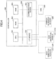
- FIG. 2 is a diagram illustrating an example of a system configuration of the operation system.
- an operation system 200 includes side operation panels 211 to 214, various in-vehicle devices 220, seat direction sensors 231 to 234, and a controller 240.
- the side operation panels 211 to 214 are input devices for operating the various in-vehicle devices 220, and include display functions and position input functions.
- the side operation panels 211 to 214 are what are known as touch panels. Display screens displayed on the side operation panels 211 to 214 include operation elements for operation of the various in-vehicle devices 220. The display screens are generated by the controller 240. Further, each of the side operation panels 211 to 214 receives an operation of an occupant, and transmits a position input signal to the controller 240.
- the various in-vehicle devices 220 may include an air conditioner 221, a lighting device 222, and an audio device 223.
- the various in-vehicle devices 220 are operated based on control signals from the controller 240.
- the seat direction sensors 231 to 234 are sensors that detect the directions of the four seats in the vehicle 100 where the driver and the passengers are seated, and are connected to the controller 240. Each of the seat direction sensors 231 to 234 outputs a forward-facing seat signal (a signal indicating that a seat is facing forward) when a corresponding occupant is seated facing the front of the vehicle 100. In addition, each of the seat direction sensors 231 to 234 outputs a rearward-facing seat signal (a signal indicating that a seat is facing rearward) when a corresponding occupant is seated facing the rear of the vehicle 100.
- the controller 240 generates display screens that include operation elements, such as for operating respective various in-vehicle devices 220, and transmits the display screens to the side operation panels 211 to 214.
- the controller 240 arranges the operation elements for operating the various in-vehicle devices 220 in accordance with signals transmitted from the seat direction sensors 231 to 234.
- the controller 240 when a position input signal is output from any of the side operation panels 211 to 214, which have received the display screens, the controller 240 generates a control signal in accordance with the position input signal, and transmits the control signal to a corresponding in-vehicle device 220.
- the controller 240 is connected to a network (controller area network (CAN) 250) in the vehicle 100, and acquires a signal indicating whether the vehicle 100 is in autonomous driving mode or in manual driving mode. Accordingly, the controller 240 can generate a display screen to be displayed on the side operation panel 211 based on whether the vehicle 100 is in autonomous driving mode or in manual driving mode.
- CAN controller area network
- FIG. 3 is diagram illustrating an example of the arrangement of components constituting the operation system.
- FIG. 3 illustrates the inside of the vehicle 100 when viewed from above.
- the side operation panel 211 is installed on the inner side of a door located beside the driver's seat 101, and is operated by the driver seated in the driver's seat 101.
- the side operation panel 212 is installed on the inner side of a door located beside a rear seat 102, and is operated by a passenger seated in the rear seat 102.
- the side operation panel 213 is installed on the inner side of a door located beside a front seat 301, and is operated by a passenger seated in the front seat 301.
- the side operation panel 214 is installed on the inner side of a door located beside a rear seat 302, and is operated by a passenger seated in the rear seat 302.
- the audio device 223 is installed at the front center position of the vehicle 100, and the air conditioner 221 is installed behind the audio device 223 (air outlets of the air conditioner 221 are located at corresponding positions of the respective seats in the vehicle 100).
- the lighting device 222 is installed at the center of each side of the vehicle 100.
- the seat direction sensor 231, the seat direction sensor 232, the seat direction sensor 233, and the seat direction sensor 234 are installed on the underside of the driver's seat 101, the rear seat 102, the front seat 301, and the rear seat 102, respectively.
- the controller 240 may be installed behind the audio device 223, for example.
- FIG. 4 is a diagram illustrating an example of the hardware configuration of the controller.
- the controller 240 includes a central processing unit (CPU) 401, a read-only memory (ROM) 402, and a random-access memory (RAM) 403.
- the controller 240 includes an interface (I/F) device 404 and a communication device 405.
- the components of the controller 240 are connected to each other via a bus 406.
- the CPU 401 is an arithmetic device that executes various programs (such as a control program to be described later) installed in the ROM 402.
- the ROM 402 is a non-volatile memory, and functions as a main storage device that stores the various programs executed by the CPU 401 and information used by the CPU 401 when executing the various programs.
- the RAM 403 is a volatile memory such as a dynamic random access memory (DRAM) or a static random access memory (SRAM).
- the RAM 403 functions as a main storage device that provides a workspace used when the various programs installed in the ROM 402 are executed by the CPU 401.
- the I/F device 404 is a connection device for connecting the side operation panels 211 to 214, the various in-vehicle devices 220, and the seat direction sensors 231 to 234.
- the communication device 405 is a communication device for communicating with the CAN 250.
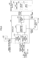
- FIG. 5 is a diagram illustrating an example of the functional configuration of the controller.
- the control program is installed in the controller 240, and the controller 240 functions as a status signal acquiring unit 510, a direction signal acquiring unit 520, an arrangement control unit 530, and an operation control unit 540 by the CPU 401 executing the control program.
- the status signal acquiring unit 510 acquires a signal indicating whether the vehicle 100 is in autonomous driving mode or in manual driving mode from the CAN 250, and transmits the signal to the arrangement control unit 530.
- the direction signal acquiring unit 520 acquires a forward-facing seat signal or a rearward-facing seat signal from each of the seat direction sensors 231 to 234, and transmits the forward-facing seat signal or the rearward-facing seat signal to the arrangement control unit 530.
- the arrangement control unit 530 monitors a forward-facing seat signal or a rearward-facing seat signal of the driver's seat 101, transmitted from the direction signal acquiring unit 520. Note that the arrangement control unit 530 monitors a forward-facing seat signal or a rearward-facing seat signal of each of the front seat 301, the rear seat 102, and the rear seat 302, regardless of whether the status signal acquiring unit 510 transmits the forward-facing seat signal or the rearward-facing seat signal.
- the arrangement control unit 530 generates display screens to be displayed on the side operation panels 211 to 214.
- a display screen generated by the arrangement control unit 530 includes a plurality of operation elements, and at least some operation elements are arranged in the longitudinal direction of the vehicle 100. While the arrangement control unit 530 monitors a forward-facing seat signal or a rearward-facing seat signal, the arrangement control unit 530 reverses the arrangement of the operation elements in the longitudinal direction of the vehicle 100 in accordance with the forward-facing seat signal or the rearward-facing seat signal.
- the arrangement control unit 530 transmits the generated display screens to the side operation panels 211 to 214. In addition, the arrangement control unit 530 transmits information indicating the arrangement of operation elements on the generated display screens.
- the operation control unit 540 acquires the information indicating the arrangement of the operation elements on the display screens, from the arrangement control unit 530. Further, in response to receiving a position input signal from any of the side operation panels 211 to 214, the operation control unit 540 identifies an operation element corresponding to the position input signal based on the acquired information indicating the arrangement of the operation elements. In addition, the operation control unit 540 transmits a control signal in accordance with the identified operation element to a corresponding in-vehicle device 220.
- FIG. 6 is a flowchart illustrating the first arrangement control process performed by the arrangement control unit.
- a display screen to be displayed on the side operation panel 211 operated by the driver is generated.
- step S601 the arrangement control unit 530 determines whether a signal indicating that the vehicle 100 is in autonomous driving mode is received from the status signal acquiring unit 510. In step S601, if it is determined that a signal indicating that the vehicle 100 is in autonomous driving mode is received (yes in step S601), the process proceeds to step S602.
- step S602 the arrangement control unit 530 generates a display screen to be displayed on the side operation panel 211 by arranging operation elements in accordance with the direction of the driver's seat.
- step S601 if it is determined that a signal indicating that the vehicle 100 is in autonomous driving mode is not received (no in step S601) (that is, a signal indicating that the vehicle 100 is in manual driving mode is received), the process proceeds to step S603.
- step S603 the arrangement control unit 530 generates a display screen to be displayed on the side operation panel 211 by using a default arrangement of operation elements.
- step S604 the arrangement control unit 530 transmits the generated display screen to the side operation panel 211. Accordingly, the display screen is displayed on the side operation panel 211.
- step S605 the arrangement control unit 530 determines whether to end the first arrangement control process. In step S605, when the arrangement control unit 530 determines not to end first the arrangement control process (no in step S605), the process returns to step S601. Conversely, in step S605, when the arrangement control unit 530 determines to end the first arrangement control process (yes in step S605), the process ends.
- FIG. 7 is a flowchart illustrating the second arrangement control process performed by the arrangement control unit.
- display screens to be displayed on the side operation panels 212, 213, and 214 operated by the passengers other than the driver are generated.
- step S701 the arrangement control unit 530 generates display screens to be displayed on the side operation panels 212, 213, and 214 by arranging operation elements in accordance with the directions of the passengers' seats.
- step S702 the arrangement control unit 530 transmits the generated display screens to the side operation panels 212, 213, and 214. Accordingly, the display screens are displayed on the side operation panels 212, 213, and 214.
- step S703 the arrangement control unit 530 determines whether to end the second arrangement control process. If the arrangement control unit 530 determines not to end the second arrangement control process in step S703 (no in step S703), the process returns to step S701. Conversely, if the arrangement control unit 530 determines to end the second arrangement control process in step S703 (yes in step S703), the process ends.
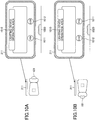
- FIGS. 8A and 8B are diagrams illustrating first examples of display screens displayed on the side operation panel 211.
- FIG. 8A illustrates an example of a display screen displayed when the driver is seated facing forward.
- the display screen is displayed on the side operation panel 211, and includes an air conditioner operation area 810 (a first area) and an audio operation area 820 (a second area) arranged in the longitudinal direction of the vehicle 100.
- the air conditioner operation area 810 includes a plurality of operation elements for the air conditioner 221, and the audio operation area 820 includes a plurality of operation elements for the audio device 223.
- the audio operation area 820 is located on the near side of the side operation panel 211 as viewed from the driver, and the air conditioner operation area 810 is located on the far side as viewed from the driver.
- the arrangement control unit 530 arranges the audio operation area 820 and the air conditioner operation area 810 such that the arrangement of the audio operation area 820 and the air conditioner operation area 810 as viewed from the driver is maintained.
- FIG. 8B illustrates an example of a display screen displayed when the driver is seated facing rearward.
- the arrangement control unit 530 reverses the arrangement of the audio operation area 820 and the air conditioner operation area 810 in the longitudinal direction of the vehicle 100.
- the audio operation area 820 is located on the near side as viewed from the driver, and the air conditioner operation area 810 is located on the far side as viewed from the driver.
- the audio operation area 820 is located on the near side as viewed from the driver, and the air conditioner operation area 810 is located on the far side as viewed from the driver.
- FIGS. 9A and 9B are diagrams illustrating second examples of display screens displayed on the side operation panel 211.
- FIG. 9A illustrates an example of a display screen displayed when the driver is seated facing forward.
- the display screen is displayed on the side operation panel 211, and includes the audio operation area 820 in which the plurality of operation elements for the audio device 223 are arranged in the longitudinal direction of the vehicle 100.
- an operation element 822 for instructing to play audio is located on the near side of the side operation panel 211 as viewed from the driver, and an operation element 821 for instructing to stop audio is located on the far side as viewed from the driver.
- the arrangement control unit 530 arranges the operation element 822 for instructing to play audio and the operation element 821 for instructing to stop audio in the audio operation area 820, such that the arrangement of the operation element 822 and the operation element 821 as viewed from the driver is maintained.
- FIG. 9B illustrates an example of a display screen displayed when the driver is seated facing rearward.
- the arrangement control unit 530 reverse the arrangement of the operation element 822 for instructing to play audio and the operation element 821 for instructing to stop audio in the longitudinal direction of the vehicle 100.
- the operation element 822 for instructing to play audio is located on the near side as viewed from the driver, and the operation element 821 for instructing to stop audio is located on the far side as viewed from the driver.
- the driver operates the side operation panel 211 after the direction of the driver's seat is changed.
- the arrangement control unit 530 when the arrangement control unit 530 reveres the operation element 822 for instructing to play audio and the operation element 821 for instructing to stop audio, the arrangement control unit 530 also reverses the orientation of the operation element 821 for instructing to play audio. Accordingly, it is possible to reduce discomfort when the driver operates the side operation panel 211 after the direction of the driver's seat is changed.
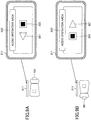
- FIGS. 10A and 10B are diagrams illustrating third examples of display screens displayed on the side operation panel.
- FIG. 10A illustrates an example of a display screen displayed when the driver is seated facing forward.
- the display screen is displayed on the side operation panel 211, and includes a lighting device operation area 1010 and guide elements for guiding operations of an operation switch 1020 that is provided outside the side operation panel 211.
- the guide elements are arranged in the longitudinal direction of the vehicle 100, and includes a guide element 1011 for guiding an opening operation of the operation switch 1020, and a guide element 1012 for guiding a closing operation of the operation switch 1020.
- the operation switch 1020 may be an operation switch for opening or closing a window beside the driver's seat 101.
- the operation switch 1020 may be configured to open the window when one of the elements is operated, and close the window when the other element is operated.
- the guide element 1012 for guiding the closing operation is located on the near side of the side operation panel 211 as viewed from the driver, and the guide element 1011 for guiding the opening operation is located on the far side as viewed from the driver.
- the arrangement control unit 530 arranges the guide element 1011 for guiding the opening operation and the guide element 1012 for guiding the closing operation, such that the arrangement of the guide element 1011 and the guide element 1012 as viewed from the driver is maintained.
- FIG. 10B illustrates an example of a display screen displayed when the driver is seated facing rearward.
- the arrangement control unit 530 reverses the arrangement of the guide element 1011 for guiding the opening operation and the guide element 1012 for guiding the closing operation in the longitudinal direction of the vehicle 100.
- the guide element 1012 for guiding the closing operation is located on the near side as viewed from the driver, and the guide element 1011 for guiding the opening operation is located on the far side as viewed from the driver.
- the assignment of control signals in accordance with the opening operation and the closing operation are controlled separately.
- the arrangement of the operation elements as viewed from the driver or a passenger is maintained, thus reducing discomfort when the driver or the passenger operates an operation panel after having changed the seat direction.
- the various in-vehicle devices 220 controlled by the controller 240 include the air conditioner 221, the lighting device 222, and the audio device 223; however, the various in-vehicle devices 220 controlled by the controller 240 are not limited thereto.
- the display screen including the air conditioner operation area 810 and the audio operation area 820 is displayed on the side operation panel 211.
- a combination of operation areas displayed on the side operation panel 211 is not limited thereto, and any combination (a combination of an operation area of a first device and an operation area of a second device) may be displayed on the side operation panel 211.
- operation elements and guide elements displayed on the side operation panel 211 have been described; however, operation elements and guide elements are not limited to those in the above-described example. Note that operation elements and guide elements that may cause discomfort to an occupant by being reversely arranged are excluded; however any other operation elements and guide elements may be reversely arranged. Examples of the operation elements and guide elements that may cause discomfort by being reversely arranged include:
- the vehicle is equipped with the four seats, and the side operation panels 211 to 214 are installed at corresponding positions of the respective four seats; however, the number of seats in the vehicle is not limited to four. In addition, the side operation panels are not required to be installed at corresponding positions of all the seats.
- the status signal acquiring unit 510, the direction signal acquiring unit 520, the arrangement control unit 530, and the operation control unit 540 are implemented by the controller 240.
- some of the functions implemented by the controller 240 may be implemented by the side operation panels 211 to 214.
Landscapes
- Engineering & Computer Science (AREA)
- Mechanical Engineering (AREA)
- Transportation (AREA)
- Aviation & Aerospace Engineering (AREA)
- Automation & Control Theory (AREA)
- Human Computer Interaction (AREA)
- Chemical & Material Sciences (AREA)
- Combustion & Propulsion (AREA)
- Physics & Mathematics (AREA)
- Thermal Sciences (AREA)
- Fittings On The Vehicle Exterior For Carrying Loads, And Devices For Holding Or Mounting Articles (AREA)
- Seats For Vehicles (AREA)
Abstract
Description
- This application is based on and claims priority to Japanese Patent Application No.
2019-157061, filed on August 29, 2019 - The disclosures herein relate to an operation system and a control method.
- Typically, the layout of seats in a vehicle is designed such that occupants are seated facing forward. For this reason, assuming that an occupant is seated facing forward, operation elements are arranged on a display of an operation panel that is disposed at a corresponding position of each of the seats in the vehicle (such as a panel disposed beside each of the seats to operate various devices).
- In recent years, the development of autonomous driving has progressed. If fully autonomous driving is put into practical use, a face-to-face seat configuration may become possible in which a driver's seat and a front passenger's seat are rotated such that occupants in the front and back can be seated facing each other.
- However, if a seat is rotated, an occupant may feel discomfort when operating an operation panel. For example, in a case where one operation element is located on the near side of the operation panel and the other operation element is located on the far side when viewed from the occupant while facing forward, the operation elements when viewed from the perspective of the occupant while facing rearward are reversed.
- [Patent Document 1] Japanese Laid-Open Patent Publication No.
9-175288 - It is a general object of the described embodiments to reduce discomfort when an occupant operates an operation panel after the direction of a seat is changed.
- The invention relates to an operation system and control method according to the appended claims. Embodiments are disclosed in the dependent claims. According to an embodiment, an operation system to be installed in a vehicle is provided. The operation system includes a memory, and a processor coupled to the memory and configured to acquire a first signal indicating whether a seat in the vehicle is facing forward or rearward, and generate a display screen by arranging at least two operation elements in a longitudinal direction of the vehicle. The display screen is displayed on an operation panel installed in the vehicle. The processor reverses the arrangement of the at least two operation elements in the longitudinal direction of the vehicle in accordance with the first signal.
- According to an embodiment, a control method includes acquiring a signal indicating whether a seat in a vehicle is facing forward or rearward, and generating a display screen by arranging at least two operation elements in a longitudinal direction of the vehicle, the display screen being displayed on an operation panel installed in the vehicle. The generating includes reversing the arrangement of the at least two operation elements in the longitudinal direction of the vehicle in accordance with the signal.
- Other objects and further features of the present invention will be apparent from the following detailed description when read in conjunction with the accompanying drawings, in which:
-
FIGS. 1A and 1B are diagrams illustrating the direction of a seat in a vehicle in which an operation system according to embodiments of the invention is installed; -
FIG. 2 is a diagram illustrating an example of a system configuration of the operation system; -
FIG. 3 is diagram illustrating an example of the arrangement of components constituting the operation system; -
FIG. 4 is a diagram illustrating an example of a hardware configuration of a controller; -
FIG. 5 is a diagram illustrating an example of a functional configuration of the controller; -
FIG. 6 is a flowchart illustrating a first arrangement control process according to an embodiment performed by an arrangement control unit; -
FIG. 7 is a flowchart illustrating a second arrangement control process according to an embodiment performed by the arrangement control unit; -
FIGS. 8A and 8B are diagrams illustrating first examples of display screens displayed on a side operation panel; -
FIGS. 9A and 9B are diagrams illustrating second examples of display screens displayed on a side operation panel; and -
FIGS. 10A and 10B are diagrams illustrating third examples of display screens displayed on a side operation panel. - According to an embodiment, it is possible to reduce discomfort when an occupant operates an operation panel after the direction of a seat is changed.
- In the following, embodiments of the present invention will be described with reference to the accompanying drawings. In the specification and drawings, elements having substantially the same functions or configurations are denoted by the same numerals, and a duplicate description thereof will not be provided.
- First, the direction of a seat in a vehicle, in which an operation system according to a first embodiment is installed, will be described.
FIGS. 1A and 1B are diagrams illustrating the direction of a seat in a vehicle in which an operation system is installed. -
FIGS. 1A and 1B illustrate simplified side views of avehicle 100 including an autonomous driving function and a manual driving function. Although side doors are not depicted for convenience of illustration inFIGS. 1A and 1B , thevehicle 100 includes a total of four doors on the sides, and side operation panels for operating various in-vehicle devices are installed on the respective side doors. -
FIG. 1A illustrates a state in which thevehicle 100 is in manual driving mode, and is being driven in a forward direction (in a direction indicated by an arrow 110) by a driver (not illustrated). As illustrated inFIG. 1A , when thevehicle 100 is in the manual driving mode, at least a driver'sseat 101 faces the front of the vehicle 100 (in the direction indicated by the arrow 110). - Conversely,
FIG. 1B illustrates a state in which thevehicle 100 is in autonomous driving mode, and is moving in the forward direction(in the direction indicated by the arrow 110). As illustrated inFIG. 1B , when thevehicle 100 is in autonomous driving mode, the driver'sseat 101 does not need to face the front of the vehicle 100 (in the direction indicated by the arrow 110), and may face the rear of the vehicle 100 (in a direction opposite to the direction indicated by the arrow 110). InFIG. 1B , an example in which the driver'sseat 101 facing rearward has been described; however, another seat (such as a front passenger's seat) may face rearward. - As described, the seats in the
vehicle 100 may be rotated to face the front or the rear of thevehicle 100. When thevehicle 100 is in autonomous driving mode, occupants may be seated face-to-face as illustrated inFIG. 1B . - Next, a system configuration of the operation system according to an embodiment installed in a
vehicle 100 will be described.FIG. 2 is a diagram illustrating an example of a system configuration of the operation system. As illustrated inFIG. 2 , anoperation system 200 includesside operation panels 211 to 214, various in-vehicle devices 220,seat direction sensors 231 to 234, and acontroller 240. - The
side operation panels 211 to 214 are input devices for operating the various in-vehicle devices 220, and include display functions and position input functions. Theside operation panels 211 to 214 are what are known as touch panels. Display screens displayed on theside operation panels 211 to 214 include operation elements for operation of the various in-vehicle devices 220. The display screens are generated by thecontroller 240. Further, each of theside operation panels 211 to 214 receives an operation of an occupant, and transmits a position input signal to thecontroller 240. - For example, the various in-
vehicle devices 220 may include anair conditioner 221, alighting device 222, and anaudio device 223. The various in-vehicle devices 220 are operated based on control signals from thecontroller 240. - The
seat direction sensors 231 to 234 are sensors that detect the directions of the four seats in thevehicle 100 where the driver and the passengers are seated, and are connected to thecontroller 240. Each of theseat direction sensors 231 to 234 outputs a forward-facing seat signal (a signal indicating that a seat is facing forward) when a corresponding occupant is seated facing the front of thevehicle 100. In addition, each of theseat direction sensors 231 to 234 outputs a rearward-facing seat signal (a signal indicating that a seat is facing rearward) when a corresponding occupant is seated facing the rear of thevehicle 100. - The
controller 240 generates display screens that include operation elements, such as for operating respective various in-vehicle devices 220, and transmits the display screens to theside operation panels 211 to 214. When thecontroller 240 generates the display screens to be displayed on theside operation panels 211 to 214, thecontroller 240 arranges the operation elements for operating the various in-vehicle devices 220 in accordance with signals transmitted from theseat direction sensors 231 to 234. In addition, when a position input signal is output from any of theside operation panels 211 to 214, which have received the display screens, thecontroller 240 generates a control signal in accordance with the position input signal, and transmits the control signal to a corresponding in-vehicle device 220. - The
controller 240 is connected to a network (controller area network (CAN) 250) in thevehicle 100, and acquires a signal indicating whether thevehicle 100 is in autonomous driving mode or in manual driving mode. Accordingly, thecontroller 240 can generate a display screen to be displayed on theside operation panel 211 based on whether thevehicle 100 is in autonomous driving mode or in manual driving mode. - Next, an example of the arrangement of components (such as the
side operation panels 211 to 214, the various in-vehicle devices 220, and theseat direction sensors 231 to 234) constituting theoperation system 200 will be described. -
FIG. 3 is diagram illustrating an example of the arrangement of components constituting the operation system.FIG. 3 illustrates the inside of thevehicle 100 when viewed from above. As illustrated inFIG. 3 , theside operation panel 211 is installed on the inner side of a door located beside the driver'sseat 101, and is operated by the driver seated in the driver'sseat 101. Similarly, theside operation panel 212 is installed on the inner side of a door located beside arear seat 102, and is operated by a passenger seated in therear seat 102. - Similarly, the
side operation panel 213 is installed on the inner side of a door located beside afront seat 301, and is operated by a passenger seated in thefront seat 301. Similarly, theside operation panel 214 is installed on the inner side of a door located beside arear seat 302, and is operated by a passenger seated in therear seat 302. - Further, as illustrated in
FIG. 3 , theaudio device 223 is installed at the front center position of thevehicle 100, and theair conditioner 221 is installed behind the audio device 223 (air outlets of theair conditioner 221 are located at corresponding positions of the respective seats in the vehicle 100). Thelighting device 222 is installed at the center of each side of thevehicle 100. - Further, as illustrated in
FIG. 3 , theseat direction sensor 231, theseat direction sensor 232, theseat direction sensor 233, and theseat direction sensor 234 are installed on the underside of the driver'sseat 101, therear seat 102, thefront seat 301, and therear seat 102, respectively. - Although not illustrated in
FIG. 3 , thecontroller 240 may be installed behind theaudio device 223, for example. - Next, a hardware configuration of the
controller 240 will be described.FIG. 4 is a diagram illustrating an example of the hardware configuration of the controller. As illustrated inFIG. 4 , thecontroller 240 includes a central processing unit (CPU) 401, a read-only memory (ROM) 402, and a random-access memory (RAM) 403. In addition, thecontroller 240 includes an interface (I/F)device 404 and acommunication device 405. The components of thecontroller 240 are connected to each other via abus 406. - The
CPU 401 is an arithmetic device that executes various programs (such as a control program to be described later) installed in theROM 402. TheROM 402 is a non-volatile memory, and functions as a main storage device that stores the various programs executed by theCPU 401 and information used by theCPU 401 when executing the various programs. - The
RAM 403 is a volatile memory such as a dynamic random access memory (DRAM) or a static random access memory (SRAM). TheRAM 403 functions as a main storage device that provides a workspace used when the various programs installed in theROM 402 are executed by theCPU 401. - The I/
F device 404 is a connection device for connecting theside operation panels 211 to 214, the various in-vehicle devices 220, and theseat direction sensors 231 to 234. Thecommunication device 405 is a communication device for communicating with theCAN 250. - Next, a functional configuration of the
controller 240 will be described.FIG. 5 is a diagram illustrating an example of the functional configuration of the controller. As described above, the control program is installed in thecontroller 240, and thecontroller 240 functions as a statussignal acquiring unit 510, a directionsignal acquiring unit 520, anarrangement control unit 530, and anoperation control unit 540 by theCPU 401 executing the control program. - The status
signal acquiring unit 510 acquires a signal indicating whether thevehicle 100 is in autonomous driving mode or in manual driving mode from theCAN 250, and transmits the signal to thearrangement control unit 530. The directionsignal acquiring unit 520 acquires a forward-facing seat signal or a rearward-facing seat signal from each of theseat direction sensors 231 to 234, and transmits the forward-facing seat signal or the rearward-facing seat signal to thearrangement control unit 530. - In response to receiving a signal indicating that the
vehicle 100 is in autonomous driving mode from the statussignal acquiring unit 510, thearrangement control unit 530 monitors a forward-facing seat signal or a rearward-facing seat signal of the driver'sseat 101, transmitted from the directionsignal acquiring unit 520. Note that thearrangement control unit 530 monitors a forward-facing seat signal or a rearward-facing seat signal of each of thefront seat 301, therear seat 102, and therear seat 302, regardless of whether the statussignal acquiring unit 510 transmits the forward-facing seat signal or the rearward-facing seat signal. - Further, the
arrangement control unit 530 generates display screens to be displayed on theside operation panels 211 to 214. A display screen generated by thearrangement control unit 530 includes a plurality of operation elements, and at least some operation elements are arranged in the longitudinal direction of thevehicle 100. While thearrangement control unit 530 monitors a forward-facing seat signal or a rearward-facing seat signal, thearrangement control unit 530 reverses the arrangement of the operation elements in the longitudinal direction of thevehicle 100 in accordance with the forward-facing seat signal or the rearward-facing seat signal. - Further, the
arrangement control unit 530 transmits the generated display screens to theside operation panels 211 to 214. In addition, thearrangement control unit 530 transmits information indicating the arrangement of operation elements on the generated display screens. - The
operation control unit 540 acquires the information indicating the arrangement of the operation elements on the display screens, from thearrangement control unit 530. Further, in response to receiving a position input signal from any of theside operation panels 211 to 214, theoperation control unit 540 identifies an operation element corresponding to the position input signal based on the acquired information indicating the arrangement of the operation elements. In addition, theoperation control unit 540 transmits a control signal in accordance with the identified operation element to a corresponding in-vehicle device 220. - Next, embodiments of a first arrangement control process performed by the
arrangement control unit 530 to generate a display screen to be displayed on theside operation panel 211 operated by the driver, and a second arrangement control process performed by thearrangement control unit 530 to generate display screens to be displayed on theside operation panels FIG. 6 is a flowchart illustrating the first arrangement control process performed by the arrangement control unit. In the first arrangement control process illustrated inFIG. 6 , a display screen to be displayed on theside operation panel 211 operated by the driver is generated. - In step S601, the
arrangement control unit 530 determines whether a signal indicating that thevehicle 100 is in autonomous driving mode is received from the statussignal acquiring unit 510. In step S601, if it is determined that a signal indicating that thevehicle 100 is in autonomous driving mode is received (yes in step S601), the process proceeds to step S602. - In step S602, the
arrangement control unit 530 generates a display screen to be displayed on theside operation panel 211 by arranging operation elements in accordance with the direction of the driver's seat. - Conversely, in step S601, if it is determined that a signal indicating that the
vehicle 100 is in autonomous driving mode is not received (no in step S601) (that is, a signal indicating that thevehicle 100 is in manual driving mode is received), the process proceeds to step S603. In step S603, thearrangement control unit 530 generates a display screen to be displayed on theside operation panel 211 by using a default arrangement of operation elements. - In step S604, the
arrangement control unit 530 transmits the generated display screen to theside operation panel 211. Accordingly, the display screen is displayed on theside operation panel 211. - In step S605, the
arrangement control unit 530 determines whether to end the first arrangement control process. In step S605, when thearrangement control unit 530 determines not to end first the arrangement control process (no in step S605), the process returns to step S601. Conversely, in step S605, when thearrangement control unit 530 determines to end the first arrangement control process (yes in step S605), the process ends. - Next, the second arrangement control process for generating display screens displayed on the
side operation panels FIG. 7 is a flowchart illustrating the second arrangement control process performed by the arrangement control unit. In the second arrangement control process illustrated inFIG. 7 , display screens to be displayed on theside operation panels - In step S701, the
arrangement control unit 530 generates display screens to be displayed on theside operation panels - In step S702, the
arrangement control unit 530 transmits the generated display screens to theside operation panels side operation panels - In step S703, the
arrangement control unit 530 determines whether to end the second arrangement control process. If thearrangement control unit 530 determines not to end the second arrangement control process in step S703 (no in step S703), the process returns to step S701. Conversely, if thearrangement control unit 530 determines to end the second arrangement control process in step S703 (yes in step S703), the process ends. - Next, examples of display screens will be described. In the following, an example of a display screen displayed on the
side operation panel 211 when the driver is seated facing forward, and an example display screen displayed on theside operation panel 211 when the driver is seated facing rearward will be described. -
FIGS. 8A and 8B are diagrams illustrating first examples of display screens displayed on theside operation panel 211.FIG. 8A illustrates an example of a display screen displayed when the driver is seated facing forward. In the example ofFIG. 8A , the display screen is displayed on theside operation panel 211, and includes an air conditioner operation area 810 (a first area) and an audio operation area 820 (a second area) arranged in the longitudinal direction of thevehicle 100. The airconditioner operation area 810 includes a plurality of operation elements for theair conditioner 221, and theaudio operation area 820 includes a plurality of operation elements for theaudio device 223. - As illustrated in
FIG. 8A , when the driver is seated facing forward, theaudio operation area 820 is located on the near side of theside operation panel 211 as viewed from the driver, and the airconditioner operation area 810 is located on the far side as viewed from the driver. - In
FIGS. 8A and 8B , thearrangement control unit 530 arranges theaudio operation area 820 and the airconditioner operation area 810 such that the arrangement of theaudio operation area 820 and the airconditioner operation area 810 as viewed from the driver is maintained. -
FIG. 8B illustrates an example of a display screen displayed when the driver is seated facing rearward. As illustrated inFIG. 8B , when the driver is seated facing rearward, thearrangement control unit 530 reverses the arrangement of theaudio operation area 820 and the airconditioner operation area 810 in the longitudinal direction of thevehicle 100. - Accordingly, even when the driver is seated facing rearward, the
audio operation area 820 is located on the near side as viewed from the driver, and the airconditioner operation area 810 is located on the far side as viewed from the driver. As a result, it is possible to reduce discomfort when the driver operates theside operation panel 211 after the direction of the driver's seat is changed. -
FIGS. 9A and 9B are diagrams illustrating second examples of display screens displayed on theside operation panel 211.FIG. 9A illustrates an example of a display screen displayed when the driver is seated facing forward. In the example ofFIG. 9A , the display screen is displayed on theside operation panel 211, and includes theaudio operation area 820 in which the plurality of operation elements for theaudio device 223 are arranged in the longitudinal direction of thevehicle 100. - As illustrated in
FIG. 9A , when the driver is seated facing forward, anoperation element 822 for instructing to play audio is located on the near side of theside operation panel 211 as viewed from the driver, and anoperation element 821 for instructing to stop audio is located on the far side as viewed from the driver. - In
FIGS. 9A and 9B , thearrangement control unit 530 arranges theoperation element 822 for instructing to play audio and theoperation element 821 for instructing to stop audio in theaudio operation area 820, such that the arrangement of theoperation element 822 and theoperation element 821 as viewed from the driver is maintained. -
FIG. 9B illustrates an example of a display screen displayed when the driver is seated facing rearward. As illustrated inFIG. 9B , when the driver is seated facing rearward, thearrangement control unit 530 reverse the arrangement of theoperation element 822 for instructing to play audio and theoperation element 821 for instructing to stop audio in the longitudinal direction of thevehicle 100. - Accordingly, even when the driver is seated facing rearward, the
operation element 822 for instructing to play audio is located on the near side as viewed from the driver, and theoperation element 821 for instructing to stop audio is located on the far side as viewed from the driver. As a result, it is possible to reduce discomfort when the driver operates theside operation panel 211 after the direction of the driver's seat is changed. - In addition, In the example of
FIG. 9B , when thearrangement control unit 530 reveres theoperation element 822 for instructing to play audio and theoperation element 821 for instructing to stop audio, thearrangement control unit 530 also reverses the orientation of theoperation element 821 for instructing to play audio. Accordingly, it is possible to reduce discomfort when the driver operates theside operation panel 211 after the direction of the driver's seat is changed. -
FIGS. 10A and 10B are diagrams illustrating third examples of display screens displayed on the side operation panel.FIG. 10A illustrates an example of a display screen displayed when the driver is seated facing forward. In the example ofFIG. 10A , the display screen is displayed on theside operation panel 211, and includes a lightingdevice operation area 1010 and guide elements for guiding operations of anoperation switch 1020 that is provided outside theside operation panel 211. The guide elements are arranged in the longitudinal direction of thevehicle 100, and includes aguide element 1011 for guiding an opening operation of theoperation switch 1020, and aguide element 1012 for guiding a closing operation of theoperation switch 1020. - For example, the
operation switch 1020 may be an operation switch for opening or closing a window beside the driver'sseat 101. Theoperation switch 1020 may be configured to open the window when one of the elements is operated, and close the window when the other element is operated. - As illustrated in
FIG. 10A , when the driver is seated facing forward, theguide element 1012 for guiding the closing operation is located on the near side of theside operation panel 211 as viewed from the driver, and theguide element 1011 for guiding the opening operation is located on the far side as viewed from the driver. - In
FIGS. 10A and 10B , thearrangement control unit 530 arranges theguide element 1011 for guiding the opening operation and theguide element 1012 for guiding the closing operation, such that the arrangement of theguide element 1011 and theguide element 1012 as viewed from the driver is maintained. -
FIG. 10B illustrates an example of a display screen displayed when the driver is seated facing rearward. As illustrated inFIG. 10B , when the driver is seated facing rearward, thearrangement control unit 530 reverses the arrangement of theguide element 1011 for guiding the opening operation and theguide element 1012 for guiding the closing operation in the longitudinal direction of thevehicle 100. - Accordingly, even when the driver is seated facing rearward, the
guide element 1012 for guiding the closing operation is located on the near side as viewed from the driver, and theguide element 1011 for guiding the opening operation is located on the far side as viewed from the driver. As a result, it is possible to reduce discomfort when the driver operates theside operation panel 211 after the direction of the driver's seat is changed. Note that the assignment of control signals in accordance with the opening operation and the closing operation (the assignment of control signals for enabling the operations in accordance with theguide element 1011 for guiding the opening operation and theguide element 1012 for guiding the closing operation) are controlled separately. - As is clear from the above description, the
operation system 200 according to the first embodiment - acquires a signal indicating whether a vehicle is in autonomous driving mode or in manual driving mode,
- generates a display screen, to be displayed on a side operation panel installed in the vehicle, by arranging at least two operation elements (or guide elements) in the longitudinal direction of the vehicle,
- monitors a forward-facing seat signal or a rearward-facing seat signal of a driver's seat when the vehicle is in autonomous driving mode, and reverses the arrangement of at least two operation elements (or guide elements) in the longitudinal direction of the vehicle in accordance with the forward-facing seat signal or the rearward-facing seat signal, and
- monitors a forward-facing seat signal or a rearward-facing seat signal of a passenger's seat (other than the driver's seat) regardless of whether the vehicle is in the autonomous driving mode, and reverses the arrangement of at least two operation elements (or guide elements) in the longitudinal direction of the vehicle in accordance with the forward-facing seat signal or the rearward-facing seat signal.
- Accordingly, in the first embodiment, the arrangement of the operation elements as viewed from the driver or a passenger is maintained, thus reducing discomfort when the driver or the passenger operates an operation panel after having changed the seat direction.
- In the above-described first embodiment, the various in-
vehicle devices 220 controlled by thecontroller 240 include theair conditioner 221, thelighting device 222, and theaudio device 223; however, the various in-vehicle devices 220 controlled by thecontroller 240 are not limited thereto. - Further, in the above-described first embodiment, in
FIGS. 8A and 8B , the display screen including the airconditioner operation area 810 and theaudio operation area 820 is displayed on theside operation panel 211. However, a combination of operation areas displayed on theside operation panel 211 is not limited thereto, and any combination (a combination of an operation area of a first device and an operation area of a second device) may be displayed on theside operation panel 211. - Further, in the above-described first embodiment, in
FIG. 9A through FIG. 10B , specific examples of operation elements and guide elements displayed on theside operation panel 211 have been described; however, operation elements and guide elements are not limited to those in the above-described example. Note that operation elements and guide elements that may cause discomfort to an occupant by being reversely arranged are excluded; however any other operation elements and guide elements may be reversely arranged. Examples of the operation elements and guide elements that may cause discomfort by being reversely arranged include: - an operation element for instructing to increase the temperature or the air flow rate of the air conditioner and an operation element for instructing to decrease the temperature or the air flow rate;
- an operation element for instructing to rewind the audio device and an operation element for instructing to forward the audio device;
- an operation element for instructing to increase the volume of the audio device and an operation element for an instruction to decrease the volume,
- an operation element for instructing to increase the illuminance of the lighting device and an operation element for instructing to decrease the illuminance, and
- any other operation elements and guide elements that instructs to change the amount or the order.
- Further, in the above-described first embodiment, the vehicle is equipped with the four seats, and the
side operation panels 211 to 214 are installed at corresponding positions of the respective four seats; however, the number of seats in the vehicle is not limited to four. In addition, the side operation panels are not required to be installed at corresponding positions of all the seats. - Further, in the above-described first embodiment, the status
signal acquiring unit 510, the directionsignal acquiring unit 520, thearrangement control unit 530, and theoperation control unit 540 are implemented by thecontroller 240. However, some of the functions implemented by thecontroller 240 may be implemented by theside operation panels 211 to 214. - Although the present invention has been described with reference to embodiments, the present invention is not limited to the configurations as described in the embodiments, and the configurations as described in the embodiments may be combined with other elements. It should be noted that combination of the elements of the above-described embodiments may be changed without departing from the scope of the claims, and may be determined in accordance with applications as appropriate.
Claims (6)
- An operation system for installation in a vehicle, the operation system comprising:a memory; anda processor coupled to the memory and configured to acquire a first signal indicating whether a seat in the vehicle is facing forward or rearward, andgenerate a display screen by arranging at least two operation elements in a longitudinal direction of the vehicle, the display screen being displayed on an operation panel installed in the vehicle, whereinthe processor is configured to reverse the arrangement of the at least two operation elements in the longitudinal direction of the vehicle in accordance with the first signal.
- The operation system according to claim 1, the processor is further configured to acquire a second signal indicating whether the vehicle is in autonomous driving mode or in manual driving mode, wherein
in a case where the second signal indicates that the vehicle is in the autonomous driving mode, the processor is configured to reverse the arrangement of the at least two operation elements in the longitudinal direction of the vehicle in accordance with the first signal. - The operation system according to claim 1 or 2, wherein the processor is further configured to receive a position input signal from the operation panel, and transmit a control signal to a device installed in the vehicle, wherein
in a case where the processor receives the position input signal from the operation panel, the processor is configured to identify an operation element corresponding to the position input signal based on information indicating the arrangement of the at least two operation elements on the display screen, and to transmit the control signal in accordance with the identified operation element. - The operation system according to one of claims 1-3, wherein, in a case where the processor generates the display screen by arranging a first area, including a plurality of first operation elements for operation of a first device, and a second area, including a plurality of second operation elements for operation of a second device, in the longitudinal direction of the vehicle, the processor is configured to reverse the arrangement of the first area and the second area in the longitudinal direction of the vehicle in accordance with the first signal, the first device and the second device being installed in the vehicle.
- The operation system according to one of claims 1-4, wherein the processor is configured to reverse an orientation of any of the at least two operation elements in the longitudinal direction of the vehicle in accordance with the first signal.
- A control method comprising:acquiring a signal indicating whether a seat in a vehicle is facing forward or rearward; andgenerating a display screen by arranging at least two operation elements in a longitudinal direction of the vehicle, the display screen being displayed on an operation panel installed in the vehicle, whereinthe generating includes reversing the arrangement of the at least two operation elements in the longitudinal direction of the vehicle in accordance with the signal.
Applications Claiming Priority (1)
| Application Number | Priority Date | Filing Date | Title |
|---|---|---|---|
| JP2019157061A JP7309524B2 (en) | 2019-08-29 | 2019-08-29 | Operation system, control device and control method |
Publications (2)
| Publication Number | Publication Date |
|---|---|
| EP3785982A1 true EP3785982A1 (en) | 2021-03-03 |
| EP3785982B1 EP3785982B1 (en) | 2023-03-22 |
Family
ID=72086710
Family Applications (1)
| Application Number | Title | Priority Date | Filing Date |
|---|---|---|---|
| EP20190837.3A Active EP3785982B1 (en) | 2019-08-29 | 2020-08-13 | Operation system and control method |
Country Status (4)
| Country | Link |
|---|---|
| US (1) | US11332045B2 (en) |
| EP (1) | EP3785982B1 (en) |
| JP (1) | JP7309524B2 (en) |
| CN (1) | CN112441017B (en) |
Families Citing this family (2)
| Publication number | Priority date | Publication date | Assignee | Title |
|---|---|---|---|---|
| CN110843794B (en) * | 2020-01-15 | 2020-05-05 | 北京三快在线科技有限公司 | Driving scene understanding method and device and trajectory planning method and device |
| JP7487593B2 (en) * | 2020-07-13 | 2024-05-21 | 株式会社デンソー | Vehicle display control device, vehicle display control system, and vehicle display control method |
Citations (4)
| Publication number | Priority date | Publication date | Assignee | Title |
|---|---|---|---|---|
| JPH09175288A (en) | 1995-12-22 | 1997-07-08 | Yazaki Corp | Sliding door switch module |
| US20180356897A1 (en) * | 2017-06-09 | 2018-12-13 | Ford Global Technologies, Llc | Vehicle display system and method |
| WO2019135358A1 (en) * | 2018-01-05 | 2019-07-11 | パナソニックIpマネジメント株式会社 | Vehicle |
| JP2019157061A (en) | 2018-03-16 | 2019-09-19 | 株式会社パイロットコーポレーション | Heat discoloration ink composition for writing instrument, and wiring instrument |
Family Cites Families (21)
| Publication number | Priority date | Publication date | Assignee | Title |
|---|---|---|---|---|
| JP2002293194A (en) * | 2001-03-30 | 2002-10-09 | Clarion Co Ltd | On-vehicle display device |
| US20070297064A1 (en) * | 2004-10-27 | 2007-12-27 | Fujitsu Ten Limited | Display Device |
| JP4997989B2 (en) * | 2007-01-23 | 2012-08-15 | アイシン・エィ・ダブリュ株式会社 | State control device, state control method, guidance control device, and guidance control method |
| JP2009002756A (en) * | 2007-06-20 | 2009-01-08 | Fujikura Ltd | Information providing apparatus and information providing method |
| JP5371360B2 (en) * | 2008-10-01 | 2013-12-18 | キヤノン株式会社 | Display control device, display control device control method, program, and storage medium |
| JP2011054186A (en) * | 2010-10-07 | 2011-03-17 | Toshiba Tec Corp | Commodity sales data processing device |
| DE102014224108A1 (en) * | 2014-11-26 | 2016-06-02 | Robert Bosch Gmbh | Method and device for operating a vehicle |
| JP6304162B2 (en) * | 2015-07-27 | 2018-04-04 | トヨタ自動車株式会社 | Vehicle seat control device |
| JP6390035B2 (en) * | 2016-05-23 | 2018-09-19 | 本田技研工業株式会社 | Vehicle control system, vehicle control method, and vehicle control program |
| JP2017214036A (en) * | 2016-06-02 | 2017-12-07 | 本田技研工業株式会社 | Vehicle control system, vehicle control method, and vehicle control program |
| JP6819086B2 (en) * | 2016-06-15 | 2021-01-27 | 株式会社デンソー | Display control device for vehicles |
| WO2018061154A1 (en) * | 2016-09-29 | 2018-04-05 | 日産自動車株式会社 | Method for adjusting switch position, and operation device for vehicle |
| DE102016226037A1 (en) * | 2016-12-22 | 2018-06-28 | Volkswagen Aktiengesellschaft | Method and driver assistance systems to assist a user of a means of transportation |
| KR102281653B1 (en) * | 2017-01-09 | 2021-07-29 | 현대자동차주식회사 | A vehicle and method for controlling the same |
| JP6628775B2 (en) * | 2017-08-09 | 2020-01-15 | 双葉電子工業株式会社 | Touch panel switch device |
| JP6996819B2 (en) * | 2017-08-09 | 2022-01-17 | 株式会社デンソーテン | Input device and input method |
| JP2019077326A (en) * | 2017-10-24 | 2019-05-23 | パイオニア株式会社 | Light-emitting device, vehicle, light emission control method, and program |
| JP2019104315A (en) * | 2017-12-11 | 2019-06-27 | トヨタ紡織株式会社 | Monitoring device of vehicle |
| JP2019119347A (en) * | 2018-01-05 | 2019-07-22 | パナソニックIpマネジメント株式会社 | vehicle |
| JP2020055433A (en) * | 2018-10-02 | 2020-04-09 | パナソニックIpマネジメント株式会社 | vehicle |
| US10814746B2 (en) * | 2018-12-17 | 2020-10-27 | Honda Motor Co., Ltd. | Rotatable seat configuration with multi-use table |
-
2019
- 2019-08-29 JP JP2019157061A patent/JP7309524B2/en active Active
-
2020
- 2020-08-03 US US16/983,199 patent/US11332045B2/en active Active
- 2020-08-13 EP EP20190837.3A patent/EP3785982B1/en active Active
- 2020-08-17 CN CN202010823713.3A patent/CN112441017B/en active Active
Patent Citations (4)
| Publication number | Priority date | Publication date | Assignee | Title |
|---|---|---|---|---|
| JPH09175288A (en) | 1995-12-22 | 1997-07-08 | Yazaki Corp | Sliding door switch module |
| US20180356897A1 (en) * | 2017-06-09 | 2018-12-13 | Ford Global Technologies, Llc | Vehicle display system and method |
| WO2019135358A1 (en) * | 2018-01-05 | 2019-07-11 | パナソニックIpマネジメント株式会社 | Vehicle |
| JP2019157061A (en) | 2018-03-16 | 2019-09-19 | 株式会社パイロットコーポレーション | Heat discoloration ink composition for writing instrument, and wiring instrument |
Also Published As
| Publication number | Publication date |
|---|---|
| JP2021031039A (en) | 2021-03-01 |
| EP3785982B1 (en) | 2023-03-22 |
| JP7309524B2 (en) | 2023-07-18 |
| CN112441017A (en) | 2021-03-05 |
| US20210061135A1 (en) | 2021-03-04 |
| US11332045B2 (en) | 2022-05-17 |
| CN112441017B (en) | 2023-07-21 |
Similar Documents
| Publication | Publication Date | Title |
|---|---|---|
| EP3785982B1 (en) | Operation system and control method | |
| CN107206899B (en) | Controlling vehicle systems with mobile devices | |
| US10639993B2 (en) | Vehicle shade assembly | |
| US10358173B2 (en) | Device and method for subdividing vehicle cab and/or storage space into a number of sub-portions | |
| CN105480046B (en) | Mounted air conditioner system | |
| EP3714356B1 (en) | Contextual and aware button-free screen articulation | |
| US20200189418A1 (en) | Rotatable seat configuration with multi-use table | |
| US20110106333A1 (en) | Interface in a vehicle and method for exchanging data | |
| KR20130126034A (en) | Sunroof integrated type monitoring device | |
| US20230339369A1 (en) | Vehicle seat auto-adjust based on rear seat occupancy | |
| JP2011006014A (en) | Sunroof device | |
| US20070085423A1 (en) | Window control switch system for vehicles | |
| WO2021104467A1 (en) | Console box assembly sliding system, method, and device, and storage medium | |
| JP2021035798A (en) | Vehicle control systems, vehicle control methods, and programs | |
| EP3828017A1 (en) | In-vehicle climate control device | |
| CN114523886B (en) | A method and system for in-vehicle interactive control | |
| US12373158B2 (en) | Control device and control method | |
| KR102246498B1 (en) | Cockpit module for autonomous vehicle and method for controlling display module position | |
| EP3882066B1 (en) | Central control unit for a vehicle interior | |
| WO2006112161A1 (en) | Vehicle-mounted communication device and method of communication | |
| JP2008019625A (en) | Vehicular automatic opening-closing device | |
| KR101573626B1 (en) | System for controlling power windows of vehicle | |
| CN114179610A (en) | Interface control method and device for heating, ventilating and adjusting automobile seat | |
| JP2024047133A (en) | Control device and computer program | |
| KR102549147B1 (en) | Surround Wanning System and Method for Vehicle |
Legal Events
| Date | Code | Title | Description |
|---|---|---|---|
| PUAI | Public reference made under article 153(3) epc to a published international application that has entered the european phase |
Free format text: ORIGINAL CODE: 0009012 |
|
| STAA | Information on the status of an ep patent application or granted ep patent |
Free format text: STATUS: THE APPLICATION HAS BEEN PUBLISHED |
|
| AK | Designated contracting states |
Kind code of ref document: A1 Designated state(s): AL AT BE BG CH CY CZ DE DK EE ES FI FR GB GR HR HU IE IS IT LI LT LU LV MC MK MT NL NO PL PT RO RS SE SI SK SM TR |
|
| AX | Request for extension of the european patent |
Extension state: BA ME |
|
| STAA | Information on the status of an ep patent application or granted ep patent |
Free format text: STATUS: REQUEST FOR EXAMINATION WAS MADE |
|
| 17P | Request for examination filed |
Effective date: 20210827 |
|
| RBV | Designated contracting states (corrected) |
Designated state(s): AL AT BE BG CH CY CZ DE DK EE ES FI FR GB GR HR HU IE IS IT LI LT LU LV MC MK MT NL NO PL PT RO RS SE SI SK SM TR |
|
| RIC1 | Information provided on ipc code assigned before grant |
Ipc: B60K 37/06 20060101ALI20220811BHEP Ipc: B60N 2/01 20060101ALI20220811BHEP Ipc: B60H 1/00 20060101ALI20220811BHEP Ipc: B60K 35/00 20060101ALI20220811BHEP Ipc: B60N 2/14 20060101ALI20220811BHEP Ipc: B60N 2/02 20060101AFI20220811BHEP |
|
| GRAP | Despatch of communication of intention to grant a patent |
Free format text: ORIGINAL CODE: EPIDOSNIGR1 |
|
| STAA | Information on the status of an ep patent application or granted ep patent |
Free format text: STATUS: GRANT OF PATENT IS INTENDED |
|
| INTG | Intention to grant announced |
Effective date: 20221020 |
|
| GRAS | Grant fee paid |
Free format text: ORIGINAL CODE: EPIDOSNIGR3 |
|
| GRAA | (expected) grant |
Free format text: ORIGINAL CODE: 0009210 |
|
| STAA | Information on the status of an ep patent application or granted ep patent |
Free format text: STATUS: THE PATENT HAS BEEN GRANTED |
|
| AK | Designated contracting states |
Kind code of ref document: B1 Designated state(s): AL AT BE BG CH CY CZ DE DK EE ES FI FR GB GR HR HU IE IS IT LI LT LU LV MC MK MT NL NO PL PT RO RS SE SI SK SM TR |
|
| REG | Reference to a national code |
Ref country code: GB Ref legal event code: FG4D |
|
| REG | Reference to a national code |
Ref country code: CH Ref legal event code: EP |
|
| REG | Reference to a national code |
Ref country code: DE Ref legal event code: R096 Ref document number: 602020008984 Country of ref document: DE |
|
| REG | Reference to a national code |
Ref country code: IE Ref legal event code: FG4D |
|
| REG | Reference to a national code |
Ref country code: AT Ref legal event code: REF Ref document number: 1555110 Country of ref document: AT Kind code of ref document: T Effective date: 20230415 |
|
| P01 | Opt-out of the competence of the unified patent court (upc) registered |
Effective date: 20230525 |
|
| REG | Reference to a national code |
Ref country code: LT Ref legal event code: MG9D |
|
| REG | Reference to a national code |
Ref country code: NL Ref legal event code: MP Effective date: 20230322 |
|
| PG25 | Lapsed in a contracting state [announced via postgrant information from national office to epo] |
Ref country code: RS Free format text: LAPSE BECAUSE OF FAILURE TO SUBMIT A TRANSLATION OF THE DESCRIPTION OR TO PAY THE FEE WITHIN THE PRESCRIBED TIME-LIMIT Effective date: 20230322 Ref country code: NO Free format text: LAPSE BECAUSE OF FAILURE TO SUBMIT A TRANSLATION OF THE DESCRIPTION OR TO PAY THE FEE WITHIN THE PRESCRIBED TIME-LIMIT Effective date: 20230622 Ref country code: LV Free format text: LAPSE BECAUSE OF FAILURE TO SUBMIT A TRANSLATION OF THE DESCRIPTION OR TO PAY THE FEE WITHIN THE PRESCRIBED TIME-LIMIT Effective date: 20230322 Ref country code: LT Free format text: LAPSE BECAUSE OF FAILURE TO SUBMIT A TRANSLATION OF THE DESCRIPTION OR TO PAY THE FEE WITHIN THE PRESCRIBED TIME-LIMIT Effective date: 20230322 Ref country code: HR Free format text: LAPSE BECAUSE OF FAILURE TO SUBMIT A TRANSLATION OF THE DESCRIPTION OR TO PAY THE FEE WITHIN THE PRESCRIBED TIME-LIMIT Effective date: 20230322 |
|
| REG | Reference to a national code |
Ref country code: AT Ref legal event code: MK05 Ref document number: 1555110 Country of ref document: AT Kind code of ref document: T Effective date: 20230322 |
|
| PG25 | Lapsed in a contracting state [announced via postgrant information from national office to epo] |
Ref country code: SE Free format text: LAPSE BECAUSE OF FAILURE TO SUBMIT A TRANSLATION OF THE DESCRIPTION OR TO PAY THE FEE WITHIN THE PRESCRIBED TIME-LIMIT Effective date: 20230322 Ref country code: NL Free format text: LAPSE BECAUSE OF FAILURE TO SUBMIT A TRANSLATION OF THE DESCRIPTION OR TO PAY THE FEE WITHIN THE PRESCRIBED TIME-LIMIT Effective date: 20230322 Ref country code: GR Free format text: LAPSE BECAUSE OF FAILURE TO SUBMIT A TRANSLATION OF THE DESCRIPTION OR TO PAY THE FEE WITHIN THE PRESCRIBED TIME-LIMIT Effective date: 20230623 Ref country code: FI Free format text: LAPSE BECAUSE OF FAILURE TO SUBMIT A TRANSLATION OF THE DESCRIPTION OR TO PAY THE FEE WITHIN THE PRESCRIBED TIME-LIMIT Effective date: 20230322 |
|
| PG25 | Lapsed in a contracting state [announced via postgrant information from national office to epo] |
Ref country code: SM Free format text: LAPSE BECAUSE OF FAILURE TO SUBMIT A TRANSLATION OF THE DESCRIPTION OR TO PAY THE FEE WITHIN THE PRESCRIBED TIME-LIMIT Effective date: 20230322 Ref country code: RO Free format text: LAPSE BECAUSE OF FAILURE TO SUBMIT A TRANSLATION OF THE DESCRIPTION OR TO PAY THE FEE WITHIN THE PRESCRIBED TIME-LIMIT Effective date: 20230322 Ref country code: PT Free format text: LAPSE BECAUSE OF FAILURE TO SUBMIT A TRANSLATION OF THE DESCRIPTION OR TO PAY THE FEE WITHIN THE PRESCRIBED TIME-LIMIT Effective date: 20230724 Ref country code: ES Free format text: LAPSE BECAUSE OF FAILURE TO SUBMIT A TRANSLATION OF THE DESCRIPTION OR TO PAY THE FEE WITHIN THE PRESCRIBED TIME-LIMIT Effective date: 20230322 Ref country code: EE Free format text: LAPSE BECAUSE OF FAILURE TO SUBMIT A TRANSLATION OF THE DESCRIPTION OR TO PAY THE FEE WITHIN THE PRESCRIBED TIME-LIMIT Effective date: 20230322 Ref country code: AT Free format text: LAPSE BECAUSE OF FAILURE TO SUBMIT A TRANSLATION OF THE DESCRIPTION OR TO PAY THE FEE WITHIN THE PRESCRIBED TIME-LIMIT Effective date: 20230322 |
|
| PG25 | Lapsed in a contracting state [announced via postgrant information from national office to epo] |
Ref country code: SK Free format text: LAPSE BECAUSE OF FAILURE TO SUBMIT A TRANSLATION OF THE DESCRIPTION OR TO PAY THE FEE WITHIN THE PRESCRIBED TIME-LIMIT Effective date: 20230322 Ref country code: PL Free format text: LAPSE BECAUSE OF FAILURE TO SUBMIT A TRANSLATION OF THE DESCRIPTION OR TO PAY THE FEE WITHIN THE PRESCRIBED TIME-LIMIT Effective date: 20230322 Ref country code: IS Free format text: LAPSE BECAUSE OF FAILURE TO SUBMIT A TRANSLATION OF THE DESCRIPTION OR TO PAY THE FEE WITHIN THE PRESCRIBED TIME-LIMIT Effective date: 20230722 |
|
| REG | Reference to a national code |
Ref country code: DE Ref legal event code: R097 Ref document number: 602020008984 Country of ref document: DE |
|
| PLBE | No opposition filed within time limit |
Free format text: ORIGINAL CODE: 0009261 |
|
| STAA | Information on the status of an ep patent application or granted ep patent |
Free format text: STATUS: NO OPPOSITION FILED WITHIN TIME LIMIT |
|
| PG25 | Lapsed in a contracting state [announced via postgrant information from national office to epo] |
Ref country code: SI Free format text: LAPSE BECAUSE OF FAILURE TO SUBMIT A TRANSLATION OF THE DESCRIPTION OR TO PAY THE FEE WITHIN THE PRESCRIBED TIME-LIMIT Effective date: 20230322 Ref country code: DK Free format text: LAPSE BECAUSE OF FAILURE TO SUBMIT A TRANSLATION OF THE DESCRIPTION OR TO PAY THE FEE WITHIN THE PRESCRIBED TIME-LIMIT Effective date: 20230322 Ref country code: CZ Free format text: LAPSE BECAUSE OF FAILURE TO SUBMIT A TRANSLATION OF THE DESCRIPTION OR TO PAY THE FEE WITHIN THE PRESCRIBED TIME-LIMIT Effective date: 20230322 |
|
| 26N | No opposition filed |
Effective date: 20240102 |
|
| PG25 | Lapsed in a contracting state [announced via postgrant information from national office to epo] |
Ref country code: MC Free format text: LAPSE BECAUSE OF FAILURE TO SUBMIT A TRANSLATION OF THE DESCRIPTION OR TO PAY THE FEE WITHIN THE PRESCRIBED TIME-LIMIT Effective date: 20230322 |
|
| REG | Reference to a national code |
Ref country code: CH Ref legal event code: PL |
|
| PG25 | Lapsed in a contracting state [announced via postgrant information from national office to epo] |
Ref country code: MC Free format text: LAPSE BECAUSE OF FAILURE TO SUBMIT A TRANSLATION OF THE DESCRIPTION OR TO PAY THE FEE WITHIN THE PRESCRIBED TIME-LIMIT Effective date: 20230322 |
|
| PG25 | Lapsed in a contracting state [announced via postgrant information from national office to epo] |
Ref country code: LU Free format text: LAPSE BECAUSE OF NON-PAYMENT OF DUE FEES Effective date: 20230813 |
|
| PG25 | Lapsed in a contracting state [announced via postgrant information from national office to epo] |
Ref country code: LU Free format text: LAPSE BECAUSE OF NON-PAYMENT OF DUE FEES Effective date: 20230813 Ref country code: CH Free format text: LAPSE BECAUSE OF NON-PAYMENT OF DUE FEES Effective date: 20230831 |
|
| REG | Reference to a national code |
Ref country code: BE Ref legal event code: MM Effective date: 20230831 |
|
| REG | Reference to a national code |
Ref country code: IE Ref legal event code: MM4A |
|
| PG25 | Lapsed in a contracting state [announced via postgrant information from national office to epo] |
Ref country code: IT Free format text: LAPSE BECAUSE OF FAILURE TO SUBMIT A TRANSLATION OF THE DESCRIPTION OR TO PAY THE FEE WITHIN THE PRESCRIBED TIME-LIMIT Effective date: 20230322 |
|
| PG25 | Lapsed in a contracting state [announced via postgrant information from national office to epo] |
Ref country code: IE Free format text: LAPSE BECAUSE OF NON-PAYMENT OF DUE FEES Effective date: 20230813 |
|
| PG25 | Lapsed in a contracting state [announced via postgrant information from national office to epo] |
Ref country code: IE Free format text: LAPSE BECAUSE OF NON-PAYMENT OF DUE FEES Effective date: 20230813 |
|
| PG25 | Lapsed in a contracting state [announced via postgrant information from national office to epo] |
Ref country code: BE Free format text: LAPSE BECAUSE OF NON-PAYMENT OF DUE FEES Effective date: 20230831 |
|
| PG25 | Lapsed in a contracting state [announced via postgrant information from national office to epo] |
Ref country code: BG Free format text: LAPSE BECAUSE OF FAILURE TO SUBMIT A TRANSLATION OF THE DESCRIPTION OR TO PAY THE FEE WITHIN THE PRESCRIBED TIME-LIMIT Effective date: 20230322 |
|
| PG25 | Lapsed in a contracting state [announced via postgrant information from national office to epo] |
Ref country code: BG Free format text: LAPSE BECAUSE OF FAILURE TO SUBMIT A TRANSLATION OF THE DESCRIPTION OR TO PAY THE FEE WITHIN THE PRESCRIBED TIME-LIMIT Effective date: 20230322 |
|
| PG25 | Lapsed in a contracting state [announced via postgrant information from national office to epo] |
Ref country code: CY Free format text: LAPSE BECAUSE OF FAILURE TO SUBMIT A TRANSLATION OF THE DESCRIPTION OR TO PAY THE FEE WITHIN THE PRESCRIBED TIME-LIMIT; INVALID AB INITIO Effective date: 20200813 |
|
| PG25 | Lapsed in a contracting state [announced via postgrant information from national office to epo] |
Ref country code: HU Free format text: LAPSE BECAUSE OF FAILURE TO SUBMIT A TRANSLATION OF THE DESCRIPTION OR TO PAY THE FEE WITHIN THE PRESCRIBED TIME-LIMIT; INVALID AB INITIO Effective date: 20200813 |
|
| PGFP | Annual fee paid to national office [announced via postgrant information from national office to epo] |
Ref country code: DE Payment date: 20250820 Year of fee payment: 6 |
|
| PGFP | Annual fee paid to national office [announced via postgrant information from national office to epo] |
Ref country code: GB Payment date: 20250820 Year of fee payment: 6 |
|
| PGFP | Annual fee paid to national office [announced via postgrant information from national office to epo] |
Ref country code: FR Payment date: 20250828 Year of fee payment: 6 |
|
| PG25 | Lapsed in a contracting state [announced via postgrant information from national office to epo] |
Ref country code: TR Free format text: LAPSE BECAUSE OF FAILURE TO SUBMIT A TRANSLATION OF THE DESCRIPTION OR TO PAY THE FEE WITHIN THE PRESCRIBED TIME-LIMIT Effective date: 20230322 |