EP3785975A1 - Control method for vehicle power supply apparatus, vehicle power supply apparatus, vehicle, and computer program product - Google Patents
Control method for vehicle power supply apparatus, vehicle power supply apparatus, vehicle, and computer program product Download PDFInfo
- Publication number
- EP3785975A1 EP3785975A1 EP20189740.2A EP20189740A EP3785975A1 EP 3785975 A1 EP3785975 A1 EP 3785975A1 EP 20189740 A EP20189740 A EP 20189740A EP 3785975 A1 EP3785975 A1 EP 3785975A1
- Authority
- EP
- European Patent Office
- Prior art keywords
- power supply
- vehicle
- electric power
- door lock
- motor
- Prior art date
- Legal status (The legal status is an assumption and is not a legal conclusion. Google has not performed a legal analysis and makes no representation as to the accuracy of the status listed.)
- Pending
Links
Images



Classifications
-
- B—PERFORMING OPERATIONS; TRANSPORTING
- B60—VEHICLES IN GENERAL
- B60L—PROPULSION OF ELECTRICALLY-PROPELLED VEHICLES; SUPPLYING ELECTRIC POWER FOR AUXILIARY EQUIPMENT OF ELECTRICALLY-PROPELLED VEHICLES; ELECTRODYNAMIC BRAKE SYSTEMS FOR VEHICLES IN GENERAL; MAGNETIC SUSPENSION OR LEVITATION FOR VEHICLES; MONITORING OPERATING VARIABLES OF ELECTRICALLY-PROPELLED VEHICLES; ELECTRIC SAFETY DEVICES FOR ELECTRICALLY-PROPELLED VEHICLES
- B60L58/00—Methods or circuit arrangements for monitoring or controlling batteries or fuel cells, specially adapted for electric vehicles
- B60L58/10—Methods or circuit arrangements for monitoring or controlling batteries or fuel cells, specially adapted for electric vehicles for monitoring or controlling batteries
- B60L58/18—Methods or circuit arrangements for monitoring or controlling batteries or fuel cells, specially adapted for electric vehicles for monitoring or controlling batteries of two or more battery modules
-
- B—PERFORMING OPERATIONS; TRANSPORTING
- B60—VEHICLES IN GENERAL
- B60L—PROPULSION OF ELECTRICALLY-PROPELLED VEHICLES; SUPPLYING ELECTRIC POWER FOR AUXILIARY EQUIPMENT OF ELECTRICALLY-PROPELLED VEHICLES; ELECTRODYNAMIC BRAKE SYSTEMS FOR VEHICLES IN GENERAL; MAGNETIC SUSPENSION OR LEVITATION FOR VEHICLES; MONITORING OPERATING VARIABLES OF ELECTRICALLY-PROPELLED VEHICLES; ELECTRIC SAFETY DEVICES FOR ELECTRICALLY-PROPELLED VEHICLES
- B60L1/00—Supplying electric power to auxiliary equipment of vehicles
-
- B—PERFORMING OPERATIONS; TRANSPORTING
- B60—VEHICLES IN GENERAL
- B60L—PROPULSION OF ELECTRICALLY-PROPELLED VEHICLES; SUPPLYING ELECTRIC POWER FOR AUXILIARY EQUIPMENT OF ELECTRICALLY-PROPELLED VEHICLES; ELECTRODYNAMIC BRAKE SYSTEMS FOR VEHICLES IN GENERAL; MAGNETIC SUSPENSION OR LEVITATION FOR VEHICLES; MONITORING OPERATING VARIABLES OF ELECTRICALLY-PROPELLED VEHICLES; ELECTRIC SAFETY DEVICES FOR ELECTRICALLY-PROPELLED VEHICLES
- B60L58/00—Methods or circuit arrangements for monitoring or controlling batteries or fuel cells, specially adapted for electric vehicles
- B60L58/10—Methods or circuit arrangements for monitoring or controlling batteries or fuel cells, specially adapted for electric vehicles for monitoring or controlling batteries
-
- B—PERFORMING OPERATIONS; TRANSPORTING
- B60—VEHICLES IN GENERAL
- B60L—PROPULSION OF ELECTRICALLY-PROPELLED VEHICLES; SUPPLYING ELECTRIC POWER FOR AUXILIARY EQUIPMENT OF ELECTRICALLY-PROPELLED VEHICLES; ELECTRODYNAMIC BRAKE SYSTEMS FOR VEHICLES IN GENERAL; MAGNETIC SUSPENSION OR LEVITATION FOR VEHICLES; MONITORING OPERATING VARIABLES OF ELECTRICALLY-PROPELLED VEHICLES; ELECTRIC SAFETY DEVICES FOR ELECTRICALLY-PROPELLED VEHICLES
- B60L15/00—Methods, circuits, or devices for controlling the traction-motor speed of electrically-propelled vehicles
- B60L15/20—Methods, circuits, or devices for controlling the traction-motor speed of electrically-propelled vehicles for control of the vehicle or its driving motor to achieve a desired performance, e.g. speed, torque, programmed variation of speed
-
- B—PERFORMING OPERATIONS; TRANSPORTING
- B60—VEHICLES IN GENERAL
- B60L—PROPULSION OF ELECTRICALLY-PROPELLED VEHICLES; SUPPLYING ELECTRIC POWER FOR AUXILIARY EQUIPMENT OF ELECTRICALLY-PROPELLED VEHICLES; ELECTRODYNAMIC BRAKE SYSTEMS FOR VEHICLES IN GENERAL; MAGNETIC SUSPENSION OR LEVITATION FOR VEHICLES; MONITORING OPERATING VARIABLES OF ELECTRICALLY-PROPELLED VEHICLES; ELECTRIC SAFETY DEVICES FOR ELECTRICALLY-PROPELLED VEHICLES
- B60L3/00—Electric devices on electrically-propelled vehicles for safety purposes; Monitoring operating variables, e.g. speed, deceleration or energy consumption
- B60L3/0007—Measures or means for preventing or attenuating collisions
-
- B—PERFORMING OPERATIONS; TRANSPORTING
- B60—VEHICLES IN GENERAL
- B60L—PROPULSION OF ELECTRICALLY-PROPELLED VEHICLES; SUPPLYING ELECTRIC POWER FOR AUXILIARY EQUIPMENT OF ELECTRICALLY-PROPELLED VEHICLES; ELECTRODYNAMIC BRAKE SYSTEMS FOR VEHICLES IN GENERAL; MAGNETIC SUSPENSION OR LEVITATION FOR VEHICLES; MONITORING OPERATING VARIABLES OF ELECTRICALLY-PROPELLED VEHICLES; ELECTRIC SAFETY DEVICES FOR ELECTRICALLY-PROPELLED VEHICLES
- B60L3/00—Electric devices on electrically-propelled vehicles for safety purposes; Monitoring operating variables, e.g. speed, deceleration or energy consumption
- B60L3/0023—Detecting, eliminating, remedying or compensating for drive train abnormalities, e.g. failures within the drive train
- B60L3/0046—Detecting, eliminating, remedying or compensating for drive train abnormalities, e.g. failures within the drive train relating to electric energy storage systems, e.g. batteries or capacitors
-
- B—PERFORMING OPERATIONS; TRANSPORTING
- B60—VEHICLES IN GENERAL
- B60L—PROPULSION OF ELECTRICALLY-PROPELLED VEHICLES; SUPPLYING ELECTRIC POWER FOR AUXILIARY EQUIPMENT OF ELECTRICALLY-PROPELLED VEHICLES; ELECTRODYNAMIC BRAKE SYSTEMS FOR VEHICLES IN GENERAL; MAGNETIC SUSPENSION OR LEVITATION FOR VEHICLES; MONITORING OPERATING VARIABLES OF ELECTRICALLY-PROPELLED VEHICLES; ELECTRIC SAFETY DEVICES FOR ELECTRICALLY-PROPELLED VEHICLES
- B60L3/00—Electric devices on electrically-propelled vehicles for safety purposes; Monitoring operating variables, e.g. speed, deceleration or energy consumption
- B60L3/04—Cutting off the power supply under fault conditions
-
- E—FIXED CONSTRUCTIONS
- E05—LOCKS; KEYS; WINDOW OR DOOR FITTINGS; SAFES
- E05B—LOCKS; ACCESSORIES THEREFOR; HANDCUFFS
- E05B77/00—Vehicle locks characterised by special functions or purposes
- E05B77/02—Vehicle locks characterised by special functions or purposes for accident situations
- E05B77/12—Automatic locking or unlocking at the moment of collision
-
- E—FIXED CONSTRUCTIONS
- E05—LOCKS; KEYS; WINDOW OR DOOR FITTINGS; SAFES
- E05B—LOCKS; ACCESSORIES THEREFOR; HANDCUFFS
- E05B81/00—Power-actuated vehicle locks
- E05B81/54—Electrical circuits
- E05B81/80—Electrical circuits characterised by the power supply; Emergency power operation
- E05B81/86—Electrical circuits characterised by the power supply; Emergency power operation using capacitors
-
- H—ELECTRICITY
- H02—GENERATION; CONVERSION OR DISTRIBUTION OF ELECTRIC POWER
- H02J—ELECTRIC POWER NETWORKS; CIRCUIT ARRANGEMENTS OR SYSTEMS FOR SUPPLYING OR DISTRIBUTING ELECTRIC POWER; SYSTEMS FOR STORING ELECTRIC ENERGY
- H02J7/00—Circuit arrangements for charging or discharging batteries or for supplying loads from batteries
- H02J7/34—Parallel operation in networks using both storage and other DC sources, e.g. providing buffering
- H02J7/345—Parallel operation in networks using both storage and other DC sources, e.g. providing buffering using capacitors as storage or buffering devices
-
- H—ELECTRICITY
- H02—GENERATION; CONVERSION OR DISTRIBUTION OF ELECTRIC POWER
- H02J—ELECTRIC POWER NETWORKS; CIRCUIT ARRANGEMENTS OR SYSTEMS FOR SUPPLYING OR DISTRIBUTING ELECTRIC POWER; SYSTEMS FOR STORING ELECTRIC ENERGY
- H02J7/00—Circuit arrangements for charging or discharging batteries or for supplying loads from batteries
- H02J7/855—Circuit arrangements for charging or discharging batteries or for supplying loads from batteries with circuits adapted for supplying loads from the battery
-
- B—PERFORMING OPERATIONS; TRANSPORTING
- B60—VEHICLES IN GENERAL
- B60L—PROPULSION OF ELECTRICALLY-PROPELLED VEHICLES; SUPPLYING ELECTRIC POWER FOR AUXILIARY EQUIPMENT OF ELECTRICALLY-PROPELLED VEHICLES; ELECTRODYNAMIC BRAKE SYSTEMS FOR VEHICLES IN GENERAL; MAGNETIC SUSPENSION OR LEVITATION FOR VEHICLES; MONITORING OPERATING VARIABLES OF ELECTRICALLY-PROPELLED VEHICLES; ELECTRIC SAFETY DEVICES FOR ELECTRICALLY-PROPELLED VEHICLES
- B60L2240/00—Control parameters of input or output; Target parameters
- B60L2240/10—Vehicle control parameters
- B60L2240/14—Acceleration
-
- Y—GENERAL TAGGING OF NEW TECHNOLOGICAL DEVELOPMENTS; GENERAL TAGGING OF CROSS-SECTIONAL TECHNOLOGIES SPANNING OVER SEVERAL SECTIONS OF THE IPC; TECHNICAL SUBJECTS COVERED BY FORMER USPC CROSS-REFERENCE ART COLLECTIONS [XRACs] AND DIGESTS
- Y02—TECHNOLOGIES OR APPLICATIONS FOR MITIGATION OR ADAPTATION AGAINST CLIMATE CHANGE
- Y02T—CLIMATE CHANGE MITIGATION TECHNOLOGIES RELATED TO TRANSPORTATION
- Y02T10/00—Road transport of goods or passengers
- Y02T10/60—Other road transportation technologies with climate change mitigation effect
- Y02T10/70—Energy storage systems for electromobility, e.g. batteries
-
- Y—GENERAL TAGGING OF NEW TECHNOLOGICAL DEVELOPMENTS; GENERAL TAGGING OF CROSS-SECTIONAL TECHNOLOGIES SPANNING OVER SEVERAL SECTIONS OF THE IPC; TECHNICAL SUBJECTS COVERED BY FORMER USPC CROSS-REFERENCE ART COLLECTIONS [XRACs] AND DIGESTS
- Y02—TECHNOLOGIES OR APPLICATIONS FOR MITIGATION OR ADAPTATION AGAINST CLIMATE CHANGE
- Y02T—CLIMATE CHANGE MITIGATION TECHNOLOGIES RELATED TO TRANSPORTATION
- Y02T10/00—Road transport of goods or passengers
- Y02T10/60—Other road transportation technologies with climate change mitigation effect
- Y02T10/72—Electric energy management in electromobility
Definitions
- the present invention relates to a control method for a vehicle power supply apparatus, a vehicle power supply apparatus, a vehicle, and a computer program product.
- a drive power supply such as a lithium-ion battery for supplying electric power to the motor is mounted on each of such vehicles.
- DC power that is output from the drive power supply is supplied to in-vehicle equipment such as an inverter, is converted into AC power, and is then supplied to the motor.
- a controller for controlling the inverter and the like and an auxiliary power supply for supplying the electric power to the controller are mounted on the electric vehicle.
- the drive power supply In order for the motor to generate high torque that is required for travel of the vehicle, the drive power supply outputs the high-voltage DC power.
- This electric power is stored as electric charges in a capacitor of a circuit in the in-vehicle equipment, and the like.
- it is obliged in regulations to reduce a voltage of the specified in-vehicle equipment to be equal to or lower than a specified value within a specified time period from the collision of the vehicle.
- the above-described auxiliary power supply is frequently provided in a motor room in a front portion of the vehicle.
- Patent document 1 An unlocking device for a vehicle door is disclosed in Patent document 1.
- This device includes a backup power supply (a spare power supply) that is independent from a primary power supply, and supplies the electric power from this backup power supply to the controller that controls the door lock.
- a backup power supply a spare power supply
- the door can be unlocked by supplying the electric power from the backup power supply to the controller.
- the present invention has been made to solve the above-described problem and therefore has a purpose of reliably unlocking a door and discharging electric power of in-vehicle equipment.
- the present invention is a control method for a vehicle power supply apparatus.
- the vehicle power supply apparatus includes: a drive power supply that supplies electric power to a motor for generating drive power of a vehicle; a motor controller that controls supply of the electric power to the motor; an auxiliary power supply that supplies the electric power to a door lock controller for controlling supply of the electric power to a door lock for locking or unlocking a door of the vehicle; and a backup power supply that is provided as a component separate from the drive power supply and the auxiliary power supply and supplies the electric power.
- the control method includes: a collision determination step of determining whether the vehicle has collided with the obstacle; a discharging step of operating the motor controller by using the electric power that is supplied from the backup power supply in the case where it is determined in the collision determination step that the vehicle has collided with the obstacle, and discharging the electric power of in-vehicle equipment that is supplied with the electric power from the drive power supply prior to the collision of the vehicle with the obstacle by supplying electric charges stored in the in-vehicle equipment to the motor; and an unlocking step of operating the door lock controller by using the electric power supplied from the backup power supply and unlocking the door after a lapse of a specified time period since initiation timing of the discharging step.
- the electric power of the in-vehicle equipment is discharged by using the electric power that is supplied from the backup power supply. Then, after the lapse of the specified time period since the initiation timing of the discharging step, in the unlocking step, the door is unlocked by using the electric power that is supplied from the backup power supply.
- initiation timing at which a prominent reduction in a voltage occurs, differs between the motor controller and the door lock controller, the electric power, an amount of which is sufficient for the operation of each thereof, is supplied. As a result, the electric power of the in-vehicle equipment can be discharged, and the door of the vehicle can be unlocked.
- the unlocking step is initiated.
- the in-vehicle equipment is an inverter.
- At least one of the drive power supply (21) and the auxiliary power supply is a battery.
- the backup power supply is a capacitor.
- the vehicle power supply apparatus further includes a relay configured to electrically connect or disconnect at least one of the in-vehicle equipment, the motor controller and the door lock controller to or from the backup power supply.
- control method further includes switching the relay so as to electrically connect at least one of the in-vehicle equipment, the motor controller and the door lock controller to the backup power supply when the vehicle collides with the obstacle.
- control method further includes switching the relay so as to electrically disconnect at least one of the in-vehicle equipment, the motor controller and the door lock controller from the backup power supply when the vehicle does not collide with the obstacle.
- another aspect of the present invention is a vehicle power supply apparatus that includes: a motor controller that controls supply of electric power to a motor for generating drive power of a vehicle; a door lock controller that controls supply of the electric power to a door lock for locking or unlocking a door of the vehicle; a drive power supply that supplies the electric power to the motor; an auxiliary power supply that supplies the electric power to the motor controller and the door lock controller; a backup power supply that is provided as a component separate from the drive power supply and the auxiliary power supply and supplies the electric power; and a collision determination device that determines whether the vehicle has collided with an obstacle.
- the motor controller is operated by using the electric power that is supplied from the backup power supply, and executes discharge control for discharging the electric power of in-vehicle equipment that is supplied with the electric power from the drive power supply prior to the collision of the vehicle with the obstacle by supplying electric charges stored in the in-vehicle equipment to the motor, and, after a lapse of a specified time period since execution initiation timing of the discharge control, the door lock controller is operated by using the electric power supplied from the backup power supply and executes unlocking control for unlocking the door.
- the electric power since the initiation timing, at which the prominent reduction in the voltage occurs, differs between the motor controller and the door lock controller, the electric power, the amount of which is sufficient for the operation of each thereof, is supplied. As a result, the electric power of the in-vehicle equipment can be discharged, and the door of the vehicle can be unlocked.
- the in-vehicle equipment is an inverter.
- At least one of the drive power supply (21) and the auxiliary power supply is a battery.
- the backup power supply is a capacitor.
- the vehicle power supply apparatus further includes a relay configured to electrically connect or disconnect at least one of the in-vehicle equipment, the motor controller and the door lock controller to or from the backup power supply.
- the relay is configured to electrically connect at least one of the in-vehicle equipment, the motor controller and the door lock controller to the backup power supply when the vehicle collides with the obstacle.
- the relay is configured to electrically disconnect at least one of the in-vehicle equipment, the motor controller and the door lock controller from the backup power supply when the vehicle does not collide with the obstacle.
- a vehicle includes a motor configured to generating drive power of the vehicle, an in-vehicle equipment configured to supply electric charges stored in the in-vehicle equipment to the motor, a door, and the above vehicle power supply apparatus.
- a computer program product includes computer-readable instructions which, when loaded and executed on the above vehicle power supply apparatus, perform the above method.
- the present invention has the purpose of providing the control method for the vehicle power supply apparatus capable of reliably unlocking the door and discharging the electric power of the in-vehicle equipment by using the electric power supplied from the backup power supply, and the vehicle power supply apparatus.
- a description will hereinafter be made on a vehicle power supply apparatus 2 according to an embodiment with reference to the accompanying drawings.
- a description will be made on a vehicle 1 on which the vehicle power supply apparatus 2 is mounted with reference to Fig. 1.
- Fig. 1 is a layout view of the vehicle 1 on which the vehicle power supply apparatus 2 is mounted, and illustrates a front portion of the vehicle 1.
- a motor room (or motor compartment) 11 is formed in front of a driver's seat and a passenger's seat, which are not illustrated, in the vehicle 1.
- a motor (or electric motor) 12 and an inverter 13 are arranged in the motor room 11.
- the motor 12 is a rotary electric machine that generates torque when being supplied with AC power and causes front wheels 10 of the vehicle 1 to rotate.
- the inverter 13 is electronic equipment that has plural capacitors and a switching element (or switching elements).
- the inverter 13 converts DC power into three-phase AC power by switching an on state and an off state of the switching element, and supplies the three-phase AC power to the motor 12.
- equipment such as an unillustrated converter is also arranged.
- the converter transforms electric power supplied from a drive power supply 21, which will be described later.
- the vehicle 1 includes a door 14d on the driver's seat side, a door 14p on the passenger's seat side, and door locks 15d, 15p for respectively locking and unlocking the doors 14d, 14p.
- Each of the door locks 15d, 15p has an actuator, which is not illustrated.
- the doors 14d, 14p are locked or unlocked when the actuator is operated on the basis of or in response to a received locking signal and a received unlocking signal.
- the vehicle power supply apparatus 2 is mounted on the vehicle 1 that has such a configuration, and supplies in-vehicle equipment with the electric power that is required for operation thereof.
- the vehicle power supply apparatus 2 includes the drive power supply 21 and an auxiliary power supply 22.
- the drive power supply 21 is a lithium-ion battery that stores the electric power.
- the drive power supply 21 is arranged in a substantially central portion of the vehicle 1 in a vehicle longitudinal direction and a vehicle width direction, extends from a position below the driver's seat and the passenger's seat of the vehicle 1 to a position below a rear seat.
- a charging port which is not illustrated, is provided on a rear side surface of the vehicle 1, and the drive power supply 21 can store the electric power that is supplied from outside of the vehicle 1 via this charging port.
- the drive power supply 21 is configured to be able to output high-voltage DC power to the inverter 13 via a harness 21a.
- the auxiliary power supply 22 is particularly a lead-acid battery capable of outputting 12-V DC power.
- the auxiliary power supply 22 is particularly arranged in the motor room 11.
- the auxiliary power supply 22 is configured to be supplied with the electric power that is generated by a generator, which is not illustrated, and be able to store the electric power.
- the vehicle power supply apparatus 2 includes a motor controller 23, door lock controllers 24d, 24p, a collision determination device 25, and an acceleration sensor 26.
- a motor controller 23 door lock controllers 24d, 24p, a collision determination device 25, and an acceleration sensor 26.
- CAN controller area network
- the motor controller 23 is an electronic controller that controls supply of the electric power to the motor 12.
- the motor controller 23 is arranged in the motor room 11.
- the motor controller 23 controls the electric power to be supplied to the motor 12 from the inverter 13 by transmitting a control signal to the inverter 13, and thereby controls operation of the motor 12.
- the door lock controllers 24d, 24p are electronic controllers that respectively control the door locks 15d, 15p.
- the door lock controllers 24d, 24p are particularly arranged near the doors 14d, 14p, respectively.
- the door lock controllers 24d, 24p respectively operate the actuators of the door locks 15d, 15p by transmitting the locking signal or the unlocking signal to the door locks 15d, 15p and thereby lock or unlock the doors 14d, 14p. That is, the door lock controllers 24d, 24p respectively supply the door locks 15d, 15p with the electric power, an amount of which is sufficient for operation of the actuators, as the locking signal or the unlocking signal.
- the door lock controllers 24d, 24p may respectively be unitized with the door locks 15d, 15p.
- the collision determination device 25 is electronic equipment that determines whether the vehicle 1 has collided with an obstacle (for example, another vehicle, a structure on a road, or the like).
- the collision determination device 25 is particularly arranged in the motor room 11.
- the collision determination device 25 receives a signal from the acceleration sensor 26 that detects acceleration of the vehicle 1, and determines whether the vehicle 1 has collided with the obstacle on the basis of the signal.
- the collision determination device 25 integrates a value that is based on the signal received from the acceleration sensor 26, and determines that the vehicle 1 has collided with the obstacle when an integral value in a specified period exceeds a threshold value.
- the collision determination device 25 transmits a collision signal to the motor controller 23, the door lock controllers 24d, 24p, and an airbag system, which is not illustrated.
- the vehicle power supply apparatus 2 includes a backup power supply 27.
- the backup power supply 27 is a capacitor capable of storing the electric power.
- the backup power supply 27 is provided as a component separate from the drive power supply 21 and the auxiliary power supply 22 and is provided below the passenger's seat.
- the backup power supply 27 has smaller capacity than the drive power supply 21 and the auxiliary power supply 22.
- auxiliary power supply routes from the auxiliary power supply 22 are indicated by solid arrows extending from the auxiliary power supply 22.
- the auxiliary power supply 22 can supply the electric power to the inverter 13, the motor controller 23, the door lock controllers 24d, 24p, and the collision determination device 25.
- Fig. 1 electric power supply routes from the backup power supply 27 are indicated by broken arrows extending from the backup power supply 27.
- the backup power supply 27 can supply the electric power to the inverter 13, the motor controller 23, and the door lock controllers 24d, 24p.
- the motor controller 23 and the door lock controllers 24d, 24p can be operated by using the electric power that is supplied from the auxiliary power supply 22.
- the motor controller 23 controls the operation of the motor 12 by controlling the inverter 13, and causes the motor 12 to generate travel torque.
- the door lock controllers 24d, 24p respectively lock or unlock the doors 14d, 14p in response to a request of an occupant or the like.
- the auxiliary power supply 22 independently outputs the electric power, the amount of which is sufficient for the operation of the motor controller 23 and the door lock controllers 24d, 24p. That is, the motor controller 23 and the door lock controllers 24d, 24p are operated by only using the electric power that is supplied from the auxiliary power supply 22 without being supplied with the electric power from the backup power supply 27.
- the motor controller 23 and the door lock controllers 24d, 24p can be operated by using the electric power that is supplied from the backup power supply 27. That is, the backup power supply 27 independently outputs the electric power, the amount of which is sufficient for the operation of the motor controller 23 and the door lock controllers 24d, 24p.
- Fig. 2 is a time chart illustrating a current flowing through the motor controller 23 and the door lock controllers 24d, 24p from the backup power supply 27.
- the collision determination device 25 determines that the vehicle 1 has collided with the obstacle. Then, the collision determination device 25 transmits the collision signal to the motor controller 23 and the door lock controllers 24d, 24p. Thereafter, the motor controller 23 that has received the collision signal first starts being operated by using the electric power that is supplied from the backup power supply 27. At this time, a current I 1 flows through the motor controller 23 from the backup power supply 27.
- the motor controller 23 which is operated by using the electric power supplied from the backup power supply 27, controls the inverter 13 and supplies the motor 12 with electric charges stored in the capacitors of the in-vehicle equipment such as the inverter 13.
- the motor controller 23 appropriately switches the switching element of the inverter 13 between the on state and the off state, and supplies the electric charges from the in-vehicle equipment to the motor 12 such that a current (referred to as an "d-axis current") with which the torque is not generated flows through the motor 12.
- d-axis current a current with which the torque is not generated flows through the motor 12.
- the motor controller 23 stops being operated by using the electric power supplied from the backup power supply 27.
- the time period t a is set as a sufficient time period (for example, five seconds) for discharging the electric power of the in-vehicle equipment.
- the door lock controllers 24d, 24p start being operated by using the electric power supplied from the backup power supply 27.
- a current I 2 flows through each of the door lock controllers 24d, 24p from the backup power supply 27.
- the current I 2 is larger than the above-described current I 1 .
- the door lock controllers 24d, 24p which are operated by using the electric power supplied from the backup power supply 27, respectively transmit the unlocking signal to the door locks 15d, 15p and operate the actuators thereof. As a result, the doors 14d, 14p are unlocked.
- the door lock controllers 24d, 24p stop being operated by using the electric power supplied from the backup power supply 27.
- the electric power of the in-vehicle equipment is discharged, and the doors 14d, 14p are unlocked.
- the occupant can safely escape through the doors 14d, 14p.
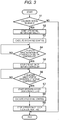
- Fig. 3 is a flowchart illustrating the processing executed by the motor controller 23 and the door lock controllers 24d, 24p. The processing is repeatedly executed in a specified cycle. All of the steps as shown in Fig. 3 may not necessarily be essential.
- step S1 the motor controller 23 and the door lock controllers 24d, 24p determine whether the collision signal is received from the collision determination device 25. If determining that the collision signal is not received (S1: NO), the motor controller 23 and the door lock controllers 24d, 24p do not use the electric power supplied from the backup power supply 27, and the processing is terminated. On the other hand, if the motor controller 23 and the door lock controllers 24d, 24p determine that the collision signal is received (S1: YES), the processing proceeds to step S2.
- Step S1 corresponds to the "collision determination step" according to the present invention.
- step S2 the motor controller 23 starts being operated by using the electric power that is supplied from the backup power supply 27. Then, in step S3, the motor controller 23 executes discharge control. That is, the motor controller 23 supplies the motor 12 with the electric charges stored in the capacitors of the in-vehicle equipment such as the inverter 13, so as to discharge the electric power of the in-vehicle equipment.
- Step S3 corresponds to a "discharging step" according to the present invention.
- step S4 the motor controller 23 determines whether the time period t a has elapsed since the initiation of the operation of the motor controller 23. If the motor controller 23 determines that the time period t a has elapsed (S4: YES), the processing proceeds to step S5.
- step S5 the motor controller 23 stops being operated by using the electric power that is supplied from the backup power supply 27. As a result, the motor controller 23 terminates the execution of the discharge control.
- step S6 the door lock controllers 24d, 24p determine whether the time period t b has elapsed since the stop of the operation of the motor controller 23 by using the electric power that is supplied from the backup power supply 27. If the door lock controllers 24d, 24p determine that the time period t b has elapsed (S6: YES), the processing proceeds to step S7.
- step S7 the door lock controllers 24d, 24p start being operated by using the electric power that is supplied from the backup power supply 27. Then, in step S8, the door lock controllers 24d, 24p execute unlocking control. That is, the door lock controllers 24d, 24p respectively operate the actuators of the door locks 15d, 15p by transmitting the unlocking signal to the door locks 15d, 15p and thereby unlock the doors 14d, 14p.
- Step S8 corresponds to an "unlocking step" according to the present invention.
- step S9 the door lock controllers 24d, 24p stop being operated by using the electric power that is supplied from the backup power supply 27.
- the discharging step the electric power of the in-vehicle equipment is discharged by using the electric power that is supplied from the backup power supply 27. Then, after the lapse of the specified time period (the time period t a illustrated in Fig. 2 ) from the initiation timing (the time t 1 illustrated in Fig. 2 ) of the discharging step, in the unlocking step, the doors 14d, 14p are unlocked by using the electric power that is supplied from the backup power supply 27.
- the electric power the amount of which is sufficient for the operation of each thereof, is supplied. As a result, the electric power of the in-vehicle equipment can be discharged, and the doors 14d, 14p of the vehicle can be unlocked.
- the unlocking step is initiated. According to this configuration, it is possible to further reliably supply the electric power, the amount of which is sufficient for the operation of each of the motor controller 23 and the door lock controllers 24d, 24p. As a result, the electric power of the in-vehicle equipment can be discharged, and the doors 14d, 14p of the vehicle 1 can be unlocked.
- the door lock controllers 24d, 24p start being operated by using the electric power supplied from the backup power supply 27.
- the present invention is not limited to this embodiment.
- the door lock controllers 24d, 24p may start being operated by using the electric power supplied from the backup power supply 27.
- Fig. 4 is a time chart illustrating a current flowing through a motor controller and door lock controllers from a backup power supply for a vehicle power supply apparatus according to another embodiment.
- the door lock controllers 24d, 24p may start being operated by using the electric power supplied from the backup power supply 27.
- the inverter 13, the motor controller 23, and the door lock controllers 24d, 24p are electrically connected to the backup power supply 27.
- a switchable relay may be provided to electrically connect/disconnect the inverter 13 and the like to/from the backup power supply 27.
- the relay is switched such that the inverter 13 and the like are electrically connected to the backup power supply 27 on the basis of the collision signal received from the collision determination device 25. In such a case, only when the vehicle 1 collides with the obstacle, the electric power can be supplied from the backup power supply 27.
Landscapes
- Engineering & Computer Science (AREA)
- Power Engineering (AREA)
- Transportation (AREA)
- Mechanical Engineering (AREA)
- Life Sciences & Earth Sciences (AREA)
- Sustainable Development (AREA)
- Sustainable Energy (AREA)
- Electric Propulsion And Braking For Vehicles (AREA)
- Lock And Its Accessories (AREA)
Abstract
Description
- The present invention relates to a control method for a vehicle power supply apparatus, a vehicle power supply apparatus, a vehicle, and a computer program product.
- In recent years, spread of electric vehicles, each of which includes a motor as a drive source, has been accelerated. A drive power supply such as a lithium-ion battery for supplying electric power to the motor is mounted on each of such vehicles. DC power that is output from the drive power supply is supplied to in-vehicle equipment such as an inverter, is converted into AC power, and is then supplied to the motor. In addition to the drive power supply, a controller for controlling the inverter and the like and an auxiliary power supply for supplying the electric power to the controller are mounted on the electric vehicle.
- In order for the motor to generate high torque that is required for travel of the vehicle, the drive power supply outputs the high-voltage DC power. This electric power is stored as electric charges in a capacitor of a circuit in the in-vehicle equipment, and the like. In order to increase safety of the vehicle at the time of a collision accident with an obstacle (for example, another vehicle, a structure on a road, or the like), it is obliged in regulations to reduce a voltage of the specified in-vehicle equipment to be equal to or lower than a specified value within a specified time period from the collision of the vehicle. As such an electric discharging method, a method for supplying the electrical charges from the in-vehicle equipment to the motor by operating the inverter and converting electrical energy into thermal energy in the motor has been known. In addition, it is obliged in the regulations to smoothly unlock vehicle doors for a prompt escape of an occupant during the collision of the vehicle.
- Due to a limitation on a space, the above-described auxiliary power supply is frequently provided in a motor room in a front portion of the vehicle. As means for further stably supplying the electric power to the controller that controls the inverter and the controller that controls door locks of the vehicle even in a case of a frontal collision of the vehicle, and the like, it is considered to mount a backup power supply on the vehicle in addition to the auxiliary power supply.
- An unlocking device for a vehicle door is disclosed in
Patent document 1. This device includes a backup power supply (a spare power supply) that is independent from a primary power supply, and supplies the electric power from this backup power supply to the controller that controls the door lock. With this configuration, even in the case where the electric power cannot be supplied from the primary power supply, the door can be unlocked by supplying the electric power from the backup power supply to the controller. - [Patent document 1]
JP-A-2003-262054 - In order to reliably comply with the above-described regulation, it is considered not only to unlock the door but also to discharge the electric power of the in-vehicle equipment by using the electric power supplied from the backup power supply. However, in the case where the backup power supply capable of outputting the high electric power in a short time is used after the collision of the vehicle, there is a problem of enlargement of the backup power supply.
- The present invention has been made to solve the above-described problem and therefore has a purpose of reliably unlocking a door and discharging electric power of in-vehicle equipment.
- In order to achieve the above-described purpose, the present invention is a control method for a vehicle power supply apparatus. The vehicle power supply apparatus includes: a drive power supply that supplies electric power to a motor for generating drive power of a vehicle; a motor controller that controls supply of the electric power to the motor; an auxiliary power supply that supplies the electric power to a door lock controller for controlling supply of the electric power to a door lock for locking or unlocking a door of the vehicle; and a backup power supply that is provided as a component separate from the drive power supply and the auxiliary power supply and supplies the electric power. The control method includes: a collision determination step of determining whether the vehicle has collided with the obstacle; a discharging step of operating the motor controller by using the electric power that is supplied from the backup power supply in the case where it is determined in the collision determination step that the vehicle has collided with the obstacle, and discharging the electric power of in-vehicle equipment that is supplied with the electric power from the drive power supply prior to the collision of the vehicle with the obstacle by supplying electric charges stored in the in-vehicle equipment to the motor; and an unlocking step of operating the door lock controller by using the electric power supplied from the backup power supply and unlocking the door after a lapse of a specified time period since initiation timing of the discharging step.
- According to this configuration, in the case where the vehicle collides with the obstacle, first, in the discharging step, the electric power of the in-vehicle equipment is discharged by using the electric power that is supplied from the backup power supply. Then, after the lapse of the specified time period since the initiation timing of the discharging step, in the unlocking step, the door is unlocked by using the electric power that is supplied from the backup power supply. Just as described, since initiation timing, at which a prominent reduction in a voltage occurs, differs between the motor controller and the door lock controller, the electric power, an amount of which is sufficient for the operation of each thereof, is supplied. As a result, the electric power of the in-vehicle equipment can be discharged, and the door of the vehicle can be unlocked.
- In the present invention, preferably, after termination of the discharging step, the unlocking step is initiated.
- According to this configuration, it is possible to further reliably supply the electric power, the amount of which is sufficient for the operation of each of the motor controller and the door lock controller. As a result, the electric power of the in-vehicle equipment can be discharged, and the door of the vehicle can be unlocked.
- Particularly, the in-vehicle equipment is an inverter.
- Further particularly, at least one of the drive power supply (21) and the auxiliary power supply is a battery.
- Further particularly, the backup power supply is a capacitor.
- Further particularly, the vehicle power supply apparatus further includes a relay configured to electrically connect or disconnect at least one of the in-vehicle equipment, the motor controller and the door lock controller to or from the backup power supply.
- Further particularly, the control method further includes switching the relay so as to electrically connect at least one of the in-vehicle equipment, the motor controller and the door lock controller to the backup power supply when the vehicle collides with the obstacle.
- Further particularly, the control method further includes switching the relay so as to electrically disconnect at least one of the in-vehicle equipment, the motor controller and the door lock controller from the backup power supply when the vehicle does not collide with the obstacle.
- In order to achieve the above-described purpose, another aspect of the present invention is a vehicle power supply apparatus that includes: a motor controller that controls supply of electric power to a motor for generating drive power of a vehicle; a door lock controller that controls supply of the electric power to a door lock for locking or unlocking a door of the vehicle; a drive power supply that supplies the electric power to the motor; an auxiliary power supply that supplies the electric power to the motor controller and the door lock controller; a backup power supply that is provided as a component separate from the drive power supply and the auxiliary power supply and supplies the electric power; and a collision determination device that determines whether the vehicle has collided with an obstacle. In the case where the collision determination device determines that the vehicle has collided with the obstacle, the motor controller is operated by using the electric power that is supplied from the backup power supply, and executes discharge control for discharging the electric power of in-vehicle equipment that is supplied with the electric power from the drive power supply prior to the collision of the vehicle with the obstacle by supplying electric charges stored in the in-vehicle equipment to the motor, and, after a lapse of a specified time period since execution initiation timing of the discharge control, the door lock controller is operated by using the electric power supplied from the backup power supply and executes unlocking control for unlocking the door.
- Also, in this aspect, since the initiation timing, at which the prominent reduction in the voltage occurs, differs between the motor controller and the door lock controller, the electric power, the amount of which is sufficient for the operation of each thereof, is supplied. As a result, the electric power of the in-vehicle equipment can be discharged, and the door of the vehicle can be unlocked.
- Particularly, the in-vehicle equipment is an inverter.
- Further particularly, at least one of the drive power supply (21) and the auxiliary power supply is a battery.
- Further particularly, the backup power supply is a capacitor.
- Further particularly, the vehicle power supply apparatus further includes a relay configured to electrically connect or disconnect at least one of the in-vehicle equipment, the motor controller and the door lock controller to or from the backup power supply.
- Further particularly, the relay is configured to electrically connect at least one of the in-vehicle equipment, the motor controller and the door lock controller to the backup power supply when the vehicle collides with the obstacle.
- Further particularly, the relay is configured to electrically disconnect at least one of the in-vehicle equipment, the motor controller and the door lock controller from the backup power supply when the vehicle does not collide with the obstacle.
- Further particularly, a vehicle includes a motor configured to generating drive power of the vehicle, an in-vehicle equipment configured to supply electric charges stored in the in-vehicle equipment to the motor, a door, and the above vehicle power supply apparatus.
- Further particularly, a computer program product includes computer-readable instructions which, when loaded and executed on the above vehicle power supply apparatus, perform the above method.
- The present invention has the purpose of providing the control method for the vehicle power supply apparatus capable of reliably unlocking the door and discharging the electric power of the in-vehicle equipment by using the electric power supplied from the backup power supply, and the vehicle power supply apparatus.
-
- [
Fig. 1] Fig. 1 is a layout view of a vehicle on which a vehicle power supply apparatus according to an embodiment is mounted. - [
Fig. 2] Fig. 2 is a time chart illustrating a current flowing through a motor controller and a door lock controller from a backup power supply inFig. 1 . - [
Fig. 3] Fig. 3 is a flowchart illustrating processing executed by the motor controller and the door lock controller inFig. 1 . - [
Fig. 4] Fig. 4 is a time chart illustrating a current flowing through a motor controller and a door lock controller from a backup power supply for a vehicle power supply apparatus according to another embodiment. - A description will hereinafter be made on a vehicle
power supply apparatus 2 according to an embodiment with reference to the accompanying drawings. First, a description will be made on avehicle 1 on which the vehiclepower supply apparatus 2 is mounted with reference toFig. 1. Fig. 1 is a layout view of thevehicle 1 on which the vehiclepower supply apparatus 2 is mounted, and illustrates a front portion of thevehicle 1. - A motor room (or motor compartment) 11 is formed in front of a driver's seat and a passenger's seat, which are not illustrated, in the
vehicle 1. A motor (or electric motor) 12 and aninverter 13 are arranged in themotor room 11. Themotor 12 is a rotary electric machine that generates torque when being supplied with AC power and causesfront wheels 10 of thevehicle 1 to rotate. Theinverter 13 is electronic equipment that has plural capacitors and a switching element (or switching elements). Theinverter 13 converts DC power into three-phase AC power by switching an on state and an off state of the switching element, and supplies the three-phase AC power to themotor 12. In themotor room 11, equipment such as an unillustrated converter is also arranged. The converter transforms electric power supplied from adrive power supply 21, which will be described later. - The
vehicle 1 includes adoor 14d on the driver's seat side, adoor 14p on the passenger's seat side, anddoor locks doors doors - The vehicle
power supply apparatus 2 is mounted on thevehicle 1 that has such a configuration, and supplies in-vehicle equipment with the electric power that is required for operation thereof. The vehiclepower supply apparatus 2 includes thedrive power supply 21 and anauxiliary power supply 22. - The
drive power supply 21 is a lithium-ion battery that stores the electric power. Thedrive power supply 21 is arranged in a substantially central portion of thevehicle 1 in a vehicle longitudinal direction and a vehicle width direction, extends from a position below the driver's seat and the passenger's seat of thevehicle 1 to a position below a rear seat. A charging port, which is not illustrated, is provided on a rear side surface of thevehicle 1, and thedrive power supply 21 can store the electric power that is supplied from outside of thevehicle 1 via this charging port. Thedrive power supply 21 is configured to be able to output high-voltage DC power to theinverter 13 via aharness 21a. - The
auxiliary power supply 22 is particularly a lead-acid battery capable of outputting 12-V DC power. Theauxiliary power supply 22 is particularly arranged in themotor room 11. Theauxiliary power supply 22 is configured to be supplied with the electric power that is generated by a generator, which is not illustrated, and be able to store the electric power. - Furthermore, the vehicle
power supply apparatus 2 includes amotor controller 23,door lock controllers collision determination device 25, and anacceleration sensor 26. These types of the in-vehicle equipment are configured to be mutually communicable by using a specified protocol via a controller area network (CAN), which is not illustrated and mounted on thevehicle 1. - The
motor controller 23 is an electronic controller that controls supply of the electric power to themotor 12. Themotor controller 23 is arranged in themotor room 11. In detail, themotor controller 23 controls the electric power to be supplied to themotor 12 from theinverter 13 by transmitting a control signal to theinverter 13, and thereby controls operation of themotor 12. - The
door lock controllers door lock controllers doors door lock controllers doors door lock controllers door lock controllers - The
collision determination device 25 is electronic equipment that determines whether thevehicle 1 has collided with an obstacle (for example, another vehicle, a structure on a road, or the like). Thecollision determination device 25 is particularly arranged in themotor room 11. Thecollision determination device 25 receives a signal from theacceleration sensor 26 that detects acceleration of thevehicle 1, and determines whether thevehicle 1 has collided with the obstacle on the basis of the signal. In detail, thecollision determination device 25 integrates a value that is based on the signal received from theacceleration sensor 26, and determines that thevehicle 1 has collided with the obstacle when an integral value in a specified period exceeds a threshold value. When determining that thevehicle 1 has collided with the obstacle, thecollision determination device 25 transmits a collision signal to themotor controller 23, thedoor lock controllers - Furthermore, the vehicle
power supply apparatus 2 includes abackup power supply 27. Thebackup power supply 27 is a capacitor capable of storing the electric power. Thebackup power supply 27 is provided as a component separate from thedrive power supply 21 and theauxiliary power supply 22 and is provided below the passenger's seat. Thebackup power supply 27 has smaller capacity than thedrive power supply 21 and theauxiliary power supply 22. - In
Fig. 1 , electric power supply routes from theauxiliary power supply 22 are indicated by solid arrows extending from theauxiliary power supply 22. Theauxiliary power supply 22 can supply the electric power to theinverter 13, themotor controller 23, thedoor lock controllers collision determination device 25. - In
Fig. 1 , electric power supply routes from thebackup power supply 27 are indicated by broken arrows extending from thebackup power supply 27. Thebackup power supply 27 can supply the electric power to theinverter 13, themotor controller 23, and thedoor lock controllers - In the case where the
vehicle 1 is operated normally without being involved in the collision with the obstacle, themotor controller 23 and thedoor lock controllers auxiliary power supply 22. Themotor controller 23 controls the operation of themotor 12 by controlling theinverter 13, and causes themotor 12 to generate travel torque. Thedoor lock controllers doors auxiliary power supply 22 independently outputs the electric power, the amount of which is sufficient for the operation of themotor controller 23 and thedoor lock controllers motor controller 23 and thedoor lock controllers auxiliary power supply 22 without being supplied with the electric power from thebackup power supply 27. - Meanwhile, in the case where the
auxiliary power supply 22 or the electric power supply route thereof fails due to the collision of thevehicle 1 with the obstacle, and thus the electric power cannot be supplied from theauxiliary power supply 22 to themotor controller 23 and thedoor lock controllers motor controller 23 and thedoor lock controllers backup power supply 27. That is, thebackup power supply 27 independently outputs the electric power, the amount of which is sufficient for the operation of themotor controller 23 and thedoor lock controllers - Next, a description will be made on the operation of the
motor controller 23 and thedoor lock controllers vehicle 1 collides with the obstacle with reference toFig. 2. Fig. 2 is a time chart illustrating a current flowing through themotor controller 23 and thedoor lock controllers backup power supply 27. - At time t1, the
collision determination device 25 determines that thevehicle 1 has collided with the obstacle. Then, thecollision determination device 25 transmits the collision signal to themotor controller 23 and thedoor lock controllers motor controller 23 that has received the collision signal first starts being operated by using the electric power that is supplied from thebackup power supply 27. At this time, a current I1 flows through themotor controller 23 from thebackup power supply 27. - The
motor controller 23, which is operated by using the electric power supplied from thebackup power supply 27, controls theinverter 13 and supplies themotor 12 with electric charges stored in the capacitors of the in-vehicle equipment such as theinverter 13. In detail, themotor controller 23 appropriately switches the switching element of theinverter 13 between the on state and the off state, and supplies the electric charges from the in-vehicle equipment to themotor 12 such that a current (referred to as an "d-axis current") with which the torque is not generated flows through themotor 12. As a result, electrical energy is converted into thermal energy in themotor 12, and the electric power of the in-vehicle equipment is discharged. - At time t2 at which a time period ta elapses from the time t1, the
motor controller 23 stops being operated by using the electric power supplied from thebackup power supply 27. The time period ta is set as a sufficient time period (for example, five seconds) for discharging the electric power of the in-vehicle equipment. - At time t3 at which a time period tb elapses from the time t2, the
door lock controllers backup power supply 27. At this time, a current I2 flows through each of thedoor lock controllers backup power supply 27. The current I2 is larger than the above-described current I1. - The
door lock controllers backup power supply 27, respectively transmit the unlocking signal to the door locks 15d, 15p and operate the actuators thereof. As a result, thedoors - At time t4 at which the transmission of the unlocking signal is completed, the
door lock controllers backup power supply 27. The electric power of the in-vehicle equipment is discharged, and thedoors doors - Next, a description will be made on processing that is executed by the
motor controller 23 and thedoor lock controllers Fig. 3. Fig. 3 is a flowchart illustrating the processing executed by themotor controller 23 and thedoor lock controllers Fig. 3 may not necessarily be essential. - In step S1, the
motor controller 23 and thedoor lock controllers collision determination device 25. If determining that the collision signal is not received (S1: NO), themotor controller 23 and thedoor lock controllers backup power supply 27, and the processing is terminated. On the other hand, if themotor controller 23 and thedoor lock controllers - In step S2, the
motor controller 23 starts being operated by using the electric power that is supplied from thebackup power supply 27. Then, in step S3, themotor controller 23 executes discharge control. That is, themotor controller 23 supplies themotor 12 with the electric charges stored in the capacitors of the in-vehicle equipment such as theinverter 13, so as to discharge the electric power of the in-vehicle equipment. Step S3 corresponds to a "discharging step" according to the present invention. - In step S4, the
motor controller 23 determines whether the time period ta has elapsed since the initiation of the operation of themotor controller 23. If themotor controller 23 determines that the time period ta has elapsed (S4: YES), the processing proceeds to step S5. - In step S5, the
motor controller 23 stops being operated by using the electric power that is supplied from thebackup power supply 27. As a result, themotor controller 23 terminates the execution of the discharge control. - In step S6, the
door lock controllers motor controller 23 by using the electric power that is supplied from thebackup power supply 27. If thedoor lock controllers - In step S7, the
door lock controllers backup power supply 27. Then, in step S8, thedoor lock controllers door lock controllers doors - After transmitting the unlocking signal, in step S9, the
door lock controllers backup power supply 27. - Next, a description will be made on operational effects based on the configuration of this embodiment.
- According to the above configuration, in the case where the
vehicle 1 collides with the obstacle, first, in the discharging step, the electric power of the in-vehicle equipment is discharged by using the electric power that is supplied from thebackup power supply 27. Then, after the lapse of the specified time period (the time period ta illustrated inFig. 2 ) from the initiation timing (the time t1 illustrated inFig. 2 ) of the discharging step, in the unlocking step, thedoors backup power supply 27. Just as described, since the initiation timing, at which the prominent reduction in the voltage occurs, differs between themotor controller 23 and thedoor lock controllers doors - After the termination of the discharging step, the unlocking step is initiated. According to this configuration, it is possible to further reliably supply the electric power, the amount of which is sufficient for the operation of each of the
motor controller 23 and thedoor lock controllers doors vehicle 1 can be unlocked. - The embodiment that has been described so far is merely provided to facilitate understanding of the present invention, and thus is not provided to limit interpretation of the present invention. Each of the elements included in the embodiment as well as arrangement, a material, a condition, a shape, size, and the like thereof is not limited to what has been exemplified above and can appropriately be changed.
- In the above embodiment, after the lapse of the time period tb since the time t2, at which the
motor controller 23 stops being operated by using the electric power supplied from thebackup power supply 27, thedoor lock controllers backup power supply 27. However, the present invention is not limited to this embodiment. For example, as illustrated inFig. 4 , at the time t2, at the same time as the stop of the operation of themotor controller 23, thedoor lock controllers backup power supply 27.Fig. 4 is a time chart illustrating a current flowing through a motor controller and door lock controllers from a backup power supply for a vehicle power supply apparatus according to another embodiment. Alternatively, prior to the stop of the operation of themotor controller 23, thedoor lock controllers backup power supply 27. - In the above embodiment, as illustrated in
Fig. 1 , theinverter 13, themotor controller 23, and thedoor lock controllers backup power supply 27. In the present invention, a switchable relay may be provided to electrically connect/disconnect theinverter 13 and the like to/from thebackup power supply 27. In this case, for example, the relay is switched such that theinverter 13 and the like are electrically connected to thebackup power supply 27 on the basis of the collision signal received from thecollision determination device 25. In such a case, only when thevehicle 1 collides with the obstacle, the electric power can be supplied from thebackup power supply 27. -
- 1:
- Vehicle
- 12:
- Motor
- 13:
- Inverter (in-vehicle equipment)
- 14d, 14p:
- Door
- 15d, 15p:
- Door lock
- 2:
- Vehicle power supply apparatus
- 21:
- Drive power supply
- 22:
- Auxiliary power supply
- 23:
- Motor controller
- 24d, 24p:
- Door lock controller
- 25:
- Collision determination device
- 27:
- Backup power supply
Claims (14)
- A control method for a vehicle power supply apparatus (2),
the vehicle power supply apparatus (2) including:a drive power supply (21) configured to supply electric power to a motor (12) configured to generate drive power of a vehicle (1);an auxiliary power supply (22) configured to supply the electric power to a motor controller (23) configured to control supply of the electric power to the motor (12) and a door lock controller (24d, 24p) configured to control supply of the electric power to a door lock (15d, 15p) configured to lock or unlock a door (14d, 14p) of the vehicle (1); anda backup power supply (27) that is provided as a component separate from the drive power supply (21) and the auxiliary power supply (22) and configured to supply the electric power,the control method comprising:a collision determination step of determining whether the vehicle (1) has collided with an obstacle;a discharging step of operating the motor controller (23) by using the electric power supplied from the backup power supply (27) in the case where it is determined in the collision determination step that the vehicle (1) has collided with the obstacle, and discharging the electric power of an in-vehicle equipment (13) that is supplied with the electric power from the drive power supply (21) prior to the collision of the vehicle (1) with the obstacle by supplying electric charges stored in the in-vehicle equipment (13) to the motor (12); andan unlocking step of operating the door lock controller (24d, 24p) by using the electric power supplied from the backup power supply (27) and unlocking the door (14d, 14p) after a lapse of a specified time period since initiation timing of the discharging step. - The control method for the vehicle power supply apparatus (2) according to claim 1, wherein
after the discharging step is terminated, the unlocking step is initiated. - The control method for the vehicle power supply apparatus according to claim 1 or 2, wherein the in-vehicle equipment (13) is an inverter.
- The control method for the vehicle power supply apparatus according to any one of the preceding claims, wherein at least one of the drive power supply (21) and the auxiliary power supply (22) is a battery.
- The control method for the vehicle power supply apparatus according to any one of the preceding claims, wherein the backup power supply (27) is a capacitor.
- The control method for the vehicle power supply apparatus according to any one of the preceding claims, wherein the vehicle power supply apparatus (2) further includes a relay configured to electrically connect or disconnect at least one of the in-vehicle equipment (13), the motor controller (23) and the door lock controller (24d, 24p) to or from the backup power supply (27),
the control method further includes
switching the relay so as to electrically connect at least one of the in-vehicle equipment (13), the motor controller (23) and the door lock controller (24d, 24p) to the backup power supply (27) when the vehicle (1) collides with the obstacle, and/or
switching the relay so as to electrically disconnect at least one of the in-vehicle equipment (13), the motor controller (23) and the door lock controller (24d, 24p) from the backup power supply (27) when the vehicle (1) does not collide with the obstacle. - A vehicle power supply apparatus (2) comprising:a motor controller (23) configured to control supply of electric power to a motor (12) configured to generate drive power of a vehicle (1);a door lock controller (24d, 24p) configured to control supply of the electric power to a door lock (15d, 15p) configured to lock or unlock a door (14d, 14p) of the vehicle (1) ;a drive power supply (21) configured to supply the electric power to the motor (12);an auxiliary power supply (22) configured to supply the electric power to the motor controller (23) and the door lock controller (24d, 24p);a backup power supply (27) that is provided as a component separate from the drive power supply (21) and the auxiliary power supply (22) and configured to supply the electric power; anda collision determination device (25) configured to determine whether the vehicle (1) has collided with an obstacle, whereinin the case where the collision determination device (25) determines that the vehicle (1) has collided with the obstacle,the motor controller (23) is configured to be operated by using the electric power that is supplied from the backup power supply (27), and configured to execute discharge control for discharging the electric power of an in-vehicle equipment (13) that is supplied with the electric power from the drive power supply (21) prior to the collision of the vehicle (1) with the obstacle by supplying electric charges stored in the in-vehicle equipment (13) to the motor (12), andafter a lapse of a specified time period since execution initiation timing of the discharge control, the door lock controller (24d, 24p) is configured to be operated by using the electric power supplied from the backup power supply (27) and configured to execute unlocking control for unlocking the door (14d, 14p).
- The vehicle power supply apparatus (2) according to claim 7, wherein
after termination of the execution of the discharge control, the door lock controller (24d, 24p) is configured to start executing the unlocking control. - The vehicle power supply apparatus according to claim 7 or 8, wherein the in-vehicle equipment (13) is an inverter.
- The vehicle power supply apparatus according to any one of claims 7 to 9, wherein at least one of the drive power supply (21) and the auxiliary power supply (22) is a battery.
- The vehicle power supply apparatus according to any one of claims 7 to 10, wherein the backup power supply (27) is a capacitor.
- The vehicle power supply apparatus according to any one of claims 7 to 11, further comprising a relay configured to electrically connect or disconnect at least one of the in-vehicle equipment (13), the motor controller (23) and the door lock controller (24d, 24p) to or from the backup power supply (27), wherein
the relay is configured to electrically connect at least one of the in-vehicle equipment (13), the motor controller (23) and the door lock controller (24d, 24p) to the backup power supply (27) when the vehicle (1) collides with the obstacle, and/or
the relay is configured to electrically disconnect at least one of the in-vehicle equipment (13), the motor controller (23) and the door lock controller (24d, 24p) from the backup power supply (27) when the vehicle (1) does not collide with the obstacle. - A vehicle (1) comprising:a motor (12) configured to generate drive power of the vehicle (1);an in-vehicle equipment (13) configured to supply electric charges stored in the in-vehicle equipment (13) to the motor (12);a door (14d, 14p); andthe vehicle power supply apparatus (2) of any one of claims 7 to 12.
- A computer program product comprising computer-readable instructions which, when loaded and executed on the vehicle power supply apparatus (2) of any one of claims 7 to 12, perform the method of any one of claims 1 to 6.
Applications Claiming Priority (1)
| Application Number | Priority Date | Filing Date | Title |
|---|---|---|---|
| JP2019150465A JP7375365B2 (en) | 2019-08-20 | 2019-08-20 | Control method for vehicle power supply device and vehicle power supply device |
Publications (1)
| Publication Number | Publication Date |
|---|---|
| EP3785975A1 true EP3785975A1 (en) | 2021-03-03 |
Family
ID=71994312
Family Applications (1)
| Application Number | Title | Priority Date | Filing Date |
|---|---|---|---|
| EP20189740.2A Pending EP3785975A1 (en) | 2019-08-20 | 2020-08-06 | Control method for vehicle power supply apparatus, vehicle power supply apparatus, vehicle, and computer program product |
Country Status (4)
| Country | Link |
|---|---|
| US (1) | US11623542B2 (en) |
| EP (1) | EP3785975A1 (en) |
| JP (1) | JP7375365B2 (en) |
| CN (1) | CN112477596B (en) |
Families Citing this family (3)
| Publication number | Priority date | Publication date | Assignee | Title |
|---|---|---|---|---|
| WO2023073974A1 (en) * | 2021-11-01 | 2023-05-04 | 株式会社EViP | Motor drive circuit |
| CN115217373B (en) * | 2022-03-31 | 2024-05-14 | 广州汽车集团股份有限公司 | Pre-crash door lock control method and device, vehicle and storage medium |
| CN115788182A (en) * | 2022-11-21 | 2023-03-14 | 东风汽车集团股份有限公司 | Automobile collision door lock unlocking system and method, electronic equipment and electric automobile |
Citations (8)
| Publication number | Priority date | Publication date | Assignee | Title |
|---|---|---|---|---|
| US20020177931A1 (en) * | 2001-05-24 | 2002-11-28 | Tatsuya Iwasaki | On-board control system and method for vehicles |
| JP2003262054A (en) | 2002-02-12 | 2003-09-19 | Arvinmeritor Light Vehicle Systems-France | Unlocking device for car doors |
| JP2006141158A (en) * | 2004-11-12 | 2006-06-01 | Toyota Motor Corp | Vehicle control device |
| WO2014030190A1 (en) * | 2012-08-24 | 2014-02-27 | ルネサスエレクトロニクス株式会社 | Control unit, semiconductor device, and method for controlling control unit |
| EP3208135A1 (en) * | 2016-02-17 | 2017-08-23 | Toyota Jidosha Kabushiki Kaisha | Vehicle |
| US20170294791A1 (en) * | 2016-04-07 | 2017-10-12 | Toyota Jidosha Kabushiki Kaisha | Electric vehicle |
| JP2018074656A (en) * | 2016-10-25 | 2018-05-10 | 株式会社今仙電機製作所 | Auxiliary power supply device for vehicle and method of driving electrical component |
| EP3396089A1 (en) * | 2015-12-22 | 2018-10-31 | Mitsui Kinzoku ACT Corporation | Automobile door locking device |
Family Cites Families (7)
| Publication number | Priority date | Publication date | Assignee | Title |
|---|---|---|---|---|
| JP2005232854A (en) * | 2004-02-20 | 2005-09-02 | Auto Network Gijutsu Kenkyusho:Kk | Door lock control device for automobile |
| JP5333348B2 (en) * | 2010-06-04 | 2013-11-06 | トヨタ自動車株式会社 | Vehicle power conversion device and vehicle including the same |
| CN102275557B (en) * | 2011-04-27 | 2013-05-22 | 奇瑞汽车股份有限公司 | Vehicle collision safety control system and control method thereof |
| JP6074586B2 (en) * | 2012-08-03 | 2017-02-08 | パナソニックIpマネジメント株式会社 | Backup power supply device and automobile using the same |
| JP2015073353A (en) * | 2013-10-02 | 2015-04-16 | トヨタ自動車株式会社 | Power conversion unit for electric vehicle |
| JP6308225B2 (en) * | 2016-01-13 | 2018-04-11 | トヨタ自動車株式会社 | In-vehicle power supply system |
| JP6998543B2 (en) * | 2017-11-21 | 2022-01-18 | パナソニックIpマネジメント株式会社 | In-vehicle power supply and vehicle equipped with it |
-
2019
- 2019-08-20 JP JP2019150465A patent/JP7375365B2/en active Active
-
2020
- 2020-08-05 CN CN202010775051.7A patent/CN112477596B/en active Active
- 2020-08-06 EP EP20189740.2A patent/EP3785975A1/en active Pending
- 2020-08-11 US US16/989,894 patent/US11623542B2/en active Active
Patent Citations (8)
| Publication number | Priority date | Publication date | Assignee | Title |
|---|---|---|---|---|
| US20020177931A1 (en) * | 2001-05-24 | 2002-11-28 | Tatsuya Iwasaki | On-board control system and method for vehicles |
| JP2003262054A (en) | 2002-02-12 | 2003-09-19 | Arvinmeritor Light Vehicle Systems-France | Unlocking device for car doors |
| JP2006141158A (en) * | 2004-11-12 | 2006-06-01 | Toyota Motor Corp | Vehicle control device |
| WO2014030190A1 (en) * | 2012-08-24 | 2014-02-27 | ルネサスエレクトロニクス株式会社 | Control unit, semiconductor device, and method for controlling control unit |
| EP3396089A1 (en) * | 2015-12-22 | 2018-10-31 | Mitsui Kinzoku ACT Corporation | Automobile door locking device |
| EP3208135A1 (en) * | 2016-02-17 | 2017-08-23 | Toyota Jidosha Kabushiki Kaisha | Vehicle |
| US20170294791A1 (en) * | 2016-04-07 | 2017-10-12 | Toyota Jidosha Kabushiki Kaisha | Electric vehicle |
| JP2018074656A (en) * | 2016-10-25 | 2018-05-10 | 株式会社今仙電機製作所 | Auxiliary power supply device for vehicle and method of driving electrical component |
Also Published As
| Publication number | Publication date |
|---|---|
| JP2021035092A (en) | 2021-03-01 |
| US20210053461A1 (en) | 2021-02-25 |
| JP7375365B2 (en) | 2023-11-08 |
| US11623542B2 (en) | 2023-04-11 |
| CN112477596A (en) | 2021-03-12 |
| CN112477596B (en) | 2024-05-03 |
Similar Documents
| Publication | Publication Date | Title |
|---|---|---|
| EP1164048B1 (en) | Method and apparatus for cutting off fuel supply of a fuel cell vehicle | |
| EP3561982B1 (en) | Power redundancy system | |
| US8489266B2 (en) | Vehicle power system | |
| JP4254890B2 (en) | Vehicle control device | |
| EP3785975A1 (en) | Control method for vehicle power supply apparatus, vehicle power supply apparatus, vehicle, and computer program product | |
| US11728672B2 (en) | Safety procedure, device for the implementation thereof, and hybrid or electric vehicle | |
| CN104136279B (en) | standby power supply device | |
| EP2738044B1 (en) | Vehicular power source device | |
| KR102103369B1 (en) | Drive unit, vehicle, and control method for drive unit | |
| JP6378267B2 (en) | vehicle | |
| JP2005020952A (en) | Vehicle control device | |
| WO2004103763A1 (en) | Control apparatus and control method for vehicle-mounted fuel cell power generation system | |
| JP2011036048A (en) | Electric vehicle | |
| JP2020127300A (en) | Vehicle power system | |
| JP2018129876A (en) | Battery system of vehicle | |
| US12187208B2 (en) | Power supply control device, control method, and storage medium | |
| KR102532337B1 (en) | System and method for discharging direct current link capacitor of inverter for driving motor | |
| JP2006187085A (en) | Capacitor discharge circuit and method for inverter device | |
| JP6750313B2 (en) | Vehicle power supply | |
| CN111146842A (en) | A power supply system and vehicle | |
| JP6686743B2 (en) | Electric vehicle | |
| JP2009291016A (en) | Power supply for vehicle, and vehicle | |
| JP6787061B2 (en) | vehicle | |
| JP2012070561A (en) | Electric vehicle | |
| JP2015089269A (en) | Electric power conversion device, and on-vehicle controller including the same |
Legal Events
| Date | Code | Title | Description |
|---|---|---|---|
| PUAI | Public reference made under article 153(3) epc to a published international application that has entered the european phase |
Free format text: ORIGINAL CODE: 0009012 |
|
| STAA | Information on the status of an ep patent application or granted ep patent |
Free format text: STATUS: THE APPLICATION HAS BEEN PUBLISHED |
|
| AK | Designated contracting states |
Kind code of ref document: A1 Designated state(s): AL AT BE BG CH CY CZ DE DK EE ES FI FR GB GR HR HU IE IS IT LI LT LU LV MC MK MT NL NO PL PT RO RS SE SI SK SM TR |
|
| AX | Request for extension of the european patent |
Extension state: BA ME |
|
| STAA | Information on the status of an ep patent application or granted ep patent |
Free format text: STATUS: REQUEST FOR EXAMINATION WAS MADE |
|
| 17P | Request for examination filed |
Effective date: 20210819 |
|
| RBV | Designated contracting states (corrected) |
Designated state(s): AL AT BE BG CH CY CZ DE DK EE ES FI FR GB GR HR HU IE IS IT LI LT LU LV MC MK MT NL NO PL PT RO RS SE SI SK SM TR |
|
| STAA | Information on the status of an ep patent application or granted ep patent |
Free format text: STATUS: EXAMINATION IS IN PROGRESS |
|
| 17Q | First examination report despatched |
Effective date: 20230127 |