EP3785808A1 - Cartridge holder for a dispenser - Google Patents
Cartridge holder for a dispenser Download PDFInfo
- Publication number
- EP3785808A1 EP3785808A1 EP19194461.0A EP19194461A EP3785808A1 EP 3785808 A1 EP3785808 A1 EP 3785808A1 EP 19194461 A EP19194461 A EP 19194461A EP 3785808 A1 EP3785808 A1 EP 3785808A1
- Authority
- EP
- European Patent Office
- Prior art keywords
- cartridges
- cartridge holder
- receptacle
- type
- rear end
- Prior art date
- Legal status (The legal status is an assumption and is not a legal conclusion. Google has not performed a legal analysis and makes no representation as to the accuracy of the status listed.)
- Withdrawn
Links
- 239000011345 viscous material Substances 0.000 claims abstract description 16
- 230000037431 insertion Effects 0.000 claims description 9
- 238000003780 insertion Methods 0.000 claims description 9
- 238000000926 separation method Methods 0.000 description 3
- 230000000694 effects Effects 0.000 description 2
- 239000000853 adhesive Substances 0.000 description 1
- 230000001070 adhesive effect Effects 0.000 description 1
- 230000000903 blocking effect Effects 0.000 description 1
- 150000001875 compounds Chemical class 0.000 description 1
- 238000010276 construction Methods 0.000 description 1
- 230000006378 damage Effects 0.000 description 1
- 238000005516 engineering process Methods 0.000 description 1
- 238000004519 manufacturing process Methods 0.000 description 1
- 239000000463 material Substances 0.000 description 1
- 238000007789 sealing Methods 0.000 description 1
Images







Classifications
-
- B—PERFORMING OPERATIONS; TRANSPORTING
- B05—SPRAYING OR ATOMISING IN GENERAL; APPLYING FLUENT MATERIALS TO SURFACES, IN GENERAL
- B05C—APPARATUS FOR APPLYING FLUENT MATERIALS TO SURFACES, IN GENERAL
- B05C17/00—Hand tools or apparatus using hand held tools, for applying liquids or other fluent materials to, for spreading applied liquids or other fluent materials on, or for partially removing applied liquids or other fluent materials from, surfaces
- B05C17/005—Hand tools or apparatus using hand held tools, for applying liquids or other fluent materials to, for spreading applied liquids or other fluent materials on, or for partially removing applied liquids or other fluent materials from, surfaces for discharging material from a reservoir or container located in or on the hand tool through an outlet orifice by pressure without using surface contacting members like pads or brushes
- B05C17/01—Hand tools or apparatus using hand held tools, for applying liquids or other fluent materials to, for spreading applied liquids or other fluent materials on, or for partially removing applied liquids or other fluent materials from, surfaces for discharging material from a reservoir or container located in or on the hand tool through an outlet orifice by pressure without using surface contacting members like pads or brushes with manually mechanically or electrically actuated piston or the like
- B05C17/0103—Hand tools or apparatus using hand held tools, for applying liquids or other fluent materials to, for spreading applied liquids or other fluent materials on, or for partially removing applied liquids or other fluent materials from, surfaces for discharging material from a reservoir or container located in or on the hand tool through an outlet orifice by pressure without using surface contacting members like pads or brushes with manually mechanically or electrically actuated piston or the like with electrically actuated piston or the like
-
- B—PERFORMING OPERATIONS; TRANSPORTING
- B05—SPRAYING OR ATOMISING IN GENERAL; APPLYING FLUENT MATERIALS TO SURFACES, IN GENERAL
- B05C—APPARATUS FOR APPLYING FLUENT MATERIALS TO SURFACES, IN GENERAL
- B05C17/00—Hand tools or apparatus using hand held tools, for applying liquids or other fluent materials to, for spreading applied liquids or other fluent materials on, or for partially removing applied liquids or other fluent materials from, surfaces
- B05C17/005—Hand tools or apparatus using hand held tools, for applying liquids or other fluent materials to, for spreading applied liquids or other fluent materials on, or for partially removing applied liquids or other fluent materials from, surfaces for discharging material from a reservoir or container located in or on the hand tool through an outlet orifice by pressure without using surface contacting members like pads or brushes
- B05C17/00553—Hand tools or apparatus using hand held tools, for applying liquids or other fluent materials to, for spreading applied liquids or other fluent materials on, or for partially removing applied liquids or other fluent materials from, surfaces for discharging material from a reservoir or container located in or on the hand tool through an outlet orifice by pressure without using surface contacting members like pads or brushes with means allowing the stock of material to consist of at least two different components
-
- B—PERFORMING OPERATIONS; TRANSPORTING
- B05—SPRAYING OR ATOMISING IN GENERAL; APPLYING FLUENT MATERIALS TO SURFACES, IN GENERAL
- B05C—APPARATUS FOR APPLYING FLUENT MATERIALS TO SURFACES, IN GENERAL
- B05C17/00—Hand tools or apparatus using hand held tools, for applying liquids or other fluent materials to, for spreading applied liquids or other fluent materials on, or for partially removing applied liquids or other fluent materials from, surfaces
- B05C17/005—Hand tools or apparatus using hand held tools, for applying liquids or other fluent materials to, for spreading applied liquids or other fluent materials on, or for partially removing applied liquids or other fluent materials from, surfaces for discharging material from a reservoir or container located in or on the hand tool through an outlet orifice by pressure without using surface contacting members like pads or brushes
- B05C17/00569—Hand tools or apparatus using hand held tools, for applying liquids or other fluent materials to, for spreading applied liquids or other fluent materials on, or for partially removing applied liquids or other fluent materials from, surfaces for discharging material from a reservoir or container located in or on the hand tool through an outlet orifice by pressure without using surface contacting members like pads or brushes with a pump in the hand tool
Definitions
- the present disclosure relates to cartridge holders for dispensers for dispensing viscous material.
- Dispensers for dispensing viscous materials are used in various technical areas, such as construction engineering, medical, or dental technology, to dispense, for example, viscous adhesives, filling material or sealing compounds.
- Said dispensers usually comprise a cartridge holder for receiving a cartridge containing the viscous material and actuating means for moving one or more pistons to urge the viscous material out of the cartridge.
- the cartridge is firmly held into place to allow using the dispenser in arbitrary orientations such as upside-down or vertical orientation.
- the cartridge may be longitudinally clamped inside the cartridge holder, for example by one or more flexible elements.
- One prerequisite for clamping the cartridge inside the cartridge holder is that the clamping element firmly engages the cartridge in order to prevent lateral movement perpendicular to the clamping direction. This usually necessitates clamping elements that specifically match the size of the cartridges so that it is not possible to use various types of cartridges with a single dispenser.
- the present disclosure is directed at a cartridge holder for a dispenser, wherein the cartridge holder is configured to alternately receive at least a first type of cartridges and a second type of cartridges containing the viscous material.
- the cartridges of the first type are different in size from the cartridges of the second type.
- the cartridge holder has a distal stop for receiving a dispensing end of the cartridges and a proximal receptacle for receiving a rear end of the cartridges.
- the receptacle is located opposite to the distal stop along a longitudinal axis of the cartridge holder and is movable along the longitudinal axis as well as spring-loaded towards the distal stop.
- the receptacle is configured to contact the rear end of the first type of cartridges at a smaller distance from a rear end of the receptacle than the rear end of the second type of cartridges.
- the shape of the receptacle may exhibit longitudinal variations that allow adaption to cartridges of different sizes.
- Such longitudinal variations may comprise radially tapered sections that accommodate cartridges of different diameter or adapters that are attachable to the front side of the receptacle. Movement of the receptacle along the longitudinal axis then may serve not only for clamping the cartridge, but also for adapting the cartridge holder to different cartridge sizes. Thereby, the different types of cartridges may vary in size along the radial direction and/or along the longitudinal direction.
- the receptacle according to the present disclosure therefore adapts in two ways to cartridges of different sizes. First, it may be positioned in its entirety at various positions along its distance of travel along the longitudinal axis. Second, it may receive the cartridges at various distances from its own rear end. If the two types of cartridges both have the same length in the longitudinal direction, receiving the different types of cartridges at different distances from the rear and of the receptacle usually means that the receptacle is placed at different positions along the longitudinal axis when clamping the different types of cartridges.
- the receptacle may be configured to receive cartridges having a single compartment. Alternatively, or additionally, it may be configured to receive cartridges having several compartments, in particular two separate compartments.
- the compartments may be positioned next to each other in a lateral direction perpendicular to the longitudinal axis.
- the first type of cartridges and the second type of cartridges may comprise compartments with different diameters in the lateral direction. Additionally, or alternatively, the compartments may exhibit different lengths in the longitudinal direction.
- the receptacle may have a single part that is only movable along the longitudinal axis in its entirety. It also may have two or more separate parts, each part being movable individually along the longitudinal axis. The individual parts may be configured to each receive a rear end of separate compartments of the cartridges.
- the receptacle may be configured to receive the different types of cartridges at varying distances from its rear end by having a locating element that is integrally connected with a base element of the receptacle and receives the rear end of the cartridges.
- the locating element may have a radially tapered section extending in the longitudinal direction.
- the receptacle may also be configured to receive the different types of cartridges at varying distances from its rear end by being fitted with different types of adapters, each adapter having a locating element.
- the individual locating elements of the adapters may contact the rear ends of the cartridges at different distances from the rear end of the receptacle.
- the adapters may be configured to be alternately attachable to a base element of the receptacle or to a locating element that is provided at the base element.
- the cartridges may comprise one or more pistons, each piston urging the viscous material out of the individual compartments at the dispensing end of the cartridges when moving the pistons towards the dispensing end of the cartridges.
- the dispenser may comprise one or more piston actuators that are movable along the longitudinal direction and are configured to engage with the one or more pistons of the cartridges to move the pistons in the longitudinal direction towards the dispensing end of the cartridges.
- the piston actuators each may comprise a rod and preferably a plunger arranged at a distal end of the rod.
- the receptacle receiving the rear end of the cartridges may have one or more piston actuator openings, whereby each piston actuator opening provides a longitudinal passage through the receptacle for one or more piston actuators.
- the receptacle may encompass the piston actuators.
- the piston actuators openings allow the piston actuators to extend through the receptacle to engage with the pistons of the cartridges while the receptacle itself may remain at its position along the longitudinal axis to firmly hold the cartridge in place.
- the dispenser may be a manual dispenser having a manual piston actuating device for moving the piston actuators, a motorized dispenser having a motorized piston actuator device, or a pneumatic dispenser having a piston actuator device that can be driven by a pressurized gas, for example air.
- the receptacle comprises a locating element having a radially tapered section that is configured to at least partly circumferentially surround, for example engage, the rear end of the cartridge.
- the radially tapered section may extend along the longitudinal axis, so that the radial dimensions of the tapered section vary along the longitudinal axis, for example narrow with increasing distance from the distal stop of the cartridge holder.
- the locating element may contact the rear end of cartridges that have different sizes in the lateral or radial direction at different longitudinal locations along its tapered section.
- the radially tapered section may serve to center the cartridges in the radial direction at a longitudinal axis of the locating element and thus to prohibit lateral shifting or skewing of the cartridges after insertion into the cartridge holder.
- the longitudinal axis of the locating element may be parallel to the longitudinal axis of the cartridge holder. It may be shifted with respect to the longitudinal axis of the cartridge holder, for example in the radial direction.
- the radially tapered section also allows for adaption to varying sizes of the cartridges in the radial direction that may, for example, result from manufacturing tolerances.
- the laterally tapered section may surround or engage the rear end of the cartridge at least over a quarter, a third or a half of its circumference.
- the radially tapered section is configured as a tapered inner side wall of a cavity formed at a front surface of the locating element, said front surface facing the distal stop of the cartridge holder.
- the cavity may be configured to receive the rear end of the cartridges. It may have an at least partially circular cross-section.
- the piston actuator opening may be provided so that the piston actuator may extend through the cavity into the cartridge.
- the tapered section has a smooth surface, for example a smooth and at least partly conical surface.
- the taper may be free of steps or edges. This allows for continuous adaption to and exact centering of cartridges with varying sizes in the radial direction.
- the tapered section has a stepped surface, for example a stepped and at least partly conical surface.
- the steps may provide bearing surfaces which the rear ends of the cartridges may lay against and may provide robust support for the cartridges in the longitudinal direction.
- the bearing surfaces may be oriented perpendicular to the longitudinal axis.
- the cartridge holder comprises an adapter that is attachable to the receptacle via an attachment structure.
- the receptacle comprises a first locating element that is configured to contact the rear end of the first type of cartridges and the adapter comprises a second locating element that is configured to contact the rear end of the second type of cartridges.
- Said adapter allows the receptacle to be adapted to different sizes of cartridges over a wide range.
- the adapter may allow the receptacle to be adapted to cartridges having different sizes in the lateral and/or longitudinal direction.
- the attachment structure may, for example, be positioned at the first locating element.
- the first locating element and/or the second locating element may be configured in the same way as it is described for the locating element mentioned above.
- the first locating element and/or the second locating element may comprise said radially tapered section.
- the attachment structure is located at a front surface of the first locating element of the receptacle.
- the adapter may be positioned between the receptacle and the distal stop of the cartridge holder and the adapter may serve to reduce the spacing between the distal stop and the locating element receiving the rear and of the cartridges.
- the adapter may cover the first locating element upon attachment to the receptacle.
- the attachment structure allows for releasable connection of the adapter to the receptacle.
- Such an attachment structure allows for variable fitting of the receptacle with the adapter.
- the attachment structure is configured as a clip-in connection.
- the clip-in connection may allow the adapter being inserted under an angle with respect to a lateral plane that is oriented perpendicular to the longitudinal axis and may prevent lateral movement of the adapter along the lateral plane after insertion.
- Such a clip-in connection provides a reliable and easy-to-use interface for the adapter.
- the attachment structure has a lateral pocket that is configured to receive a lateral ridge of the adapter and a lateral stop that is located opposite of the pocket in the lateral direction and that is configured to limit lateral movement of the adapter after insertion of the ridge into the pocket.
- the adapter may comprise a recess, for example a notch, for receiving the lateral stop of the attachment structure.
- the adapter is rotatable attachable to the attachment structure, for example upon rotation about its longitudinal axis.
- Such an attachment structure may comprise a threaded element, for example an inner or outer thread, positioned at the receptacle.
- the attachment structure is configured as a rotating bayonet fitting.
- This allows easy attachment of the adapter without the need to turn the adapter several times around its longitudinal axis.
- the rotating bayonet fitting may be configured to receive the adapter upon rotation by at most 120°, for example at most 90°, 60° or 40° and/or by at least 10°, for example at least 20° or at least 40°.
- a central longitudinal axis of the second locating element of the attached adapter is laterally shifted with respect to a central longitudinal axis of the first locating element. This allows to center cartridges or individual compartments of the cartridges of the first and second type at different positions in the lateral direction. If the cartridges are, for example, configured as two-compartment cartridges, centering the individual compartments of the cartridges at different positions in the lateral direction allows to align the dispensing end of the cartridge, for example an outlet of the cartridges, with the distal stop irrespective of the size of the individual compartments.
- the first locating element has a first cavity for receiving the rear end of the first type of cartridges and the second locating element has a second cavity for receiving the rear end of the second type of cartridges, wherein the second cavity has a smaller extension perpendicular to the longitudinal axis than the first cavity.
- the first and second cavity may be configured as described in connection with the cavity mentioned above.
- the first and/or second cavity may comprise a tapered inner side wall.
- the receptacle comprises a first part for receiving a rear end of a first compartment of a two-component cartridge and a separate second part for receiving a rear end of a second compartment of the two-component cartridge, wherein the first part and the second part are placed next to each other in a lateral direction that is perpendicular to the longitudinal axis and are independently movable along the longitudinal axis.
- the first and second part of the receptacle may individually adapt to cartridges having compartments of different sizes in the longitudinal and/or lateral direction.
- the individual parts of the receptacle may each comprise the locating element that has been described above. Additionally, or alternatively, the individual parts may each comprise the attachment structure that has been described above.
- the first part and the second part form a common cavity for receiving the rear ends of the first and second type of cartridges. This allows for a secure fixation of the cartridges in the cartridge holder. Furthermore, the compartments of the cartridges may be connected together in an interspace between the compartments and the connecting structure may be received inside the common cavity.
- the cartridge holder comprises at least one first longitudinal rod and at least one second longitudinal rod, wherein the first part is longitudinally guided by the at least one first longitudinal rod and the second part is longitudinally guided by the at least one second longitudinal rod.
- the longitudinal rods extend between a proximal end of the cartridge holder and the distal stop.
- the first part may, for example, encompass the at least one first rod, but not the at least one second rod, and/or the second part may encompass the at least one second rod, but not the at least one first rod.
- the longitudinal rods may additionally join the distal stop and the proximal end of the cartridge holder.
- At least one first spring element spring-loading the first part is located around one of the first longitudinal rods and at least one second spring element spring-loading the second part is located around one of the second longitudinal rods.
- the spring elements may individually bias the first and second part of the receptacle towards the distal stop of the cartridge holder.
- the cartridge holder comprises a housing surrounding a distance of travel along which the receptacle is longitudinally movable. This prevents any objects from blocking the distance of travel and minimizes potential injuries of a user of the dispenser.
- the housing has a front plate with an opening, wherein a portion of the receptacle that is configured to contact the rear end of the cartridges extends through the opening. This facilitates insertion of the cartridges into the receptacle.
- the opening may additionally provide guidance of the receptacle in the longitudinal direction.
- the portion of the receptacle that extends through the opening may, for example, be at least a part of the locating element.
- the present disclosure is directed at a cartridge holder for a dispenser, the cartridge holder being configured to alternately receive at least a first type of two-component cartridges and a second type of two-component cartridges containing viscous material.
- the cartridges of the first type are different in size from the cartridges of the second type.
- the cartridge holder has a distal stop for receiving a dispensing end of the cartridges and a proximal receptacle for receiving a rear end of the cartridges.
- the receptacle is located opposite to the distal stop along a longitudinal axis of the cartridge holder, while the receptacle is movable along the longitudinal axis and spring-loaded towards the distal stop.
- the receptacle comprises a first part and a separate second part, wherein the first part is configured to receive a rear end of a first compartment of the two-component cartridges and the separate second part is configured to receive a rear end of a second compartment of the two-component cartridges.
- the first part and the second part are placed next to each other in a lateral direction that is perpendicular to the longitudinal axis and are independently movable along the longitudinal axis.
- Said cartridge holder solves the problem to receive various types of cartridges and simultaneously provide for reliable clamping of the cartridges by having a receptacle with two separate and independently movable parts.
- This allows for insertion of different types of cartridges that have compartments with varying lengths in the longitudinal direction.
- the cartridges may have compartments with unequal sizes in the longitudinal direction and a length difference between the compartments in the longitudinal direction may vary across the different type of cartridges.
- one type of cartridges may have compartments with a first length difference in the longitudinal direction and another type of cartridges may have compartments with a second length difference that differs from the first length difference.
- the first part and/or the second part may comprise the locating element and/or the attachment structure described above.
- all technical effects and embodiments of the locating element and/or the attachment structure described above also apply to the receptacle having two separate parts.
- the present disclosure is directed at a dispenser for dispensing viscous material having the cartridge holder described above.
- a dispenser for dispensing viscous material having the cartridge holder described above.
- Fig. 1 depicts a dispenser 1 having a cartridge holder 10 and a piston actuating device 3.
- the cartridge holder 10 is configured to hold varying types of cartridges containing viscous material.
- the cartridge holder 10 has a distal stop 25 and a clamping arrangement 22.
- the clamping arrangement 22 is located at a proximal end 20 of the cartridge holder 10 and the distal stop 25 is located opposite to the clamping arrangement 22 along a longitudinal axis 12 of the cartridge holder 10.
- the distal stop 25 and the clamping arrangement 22 are longitudinally connected by two first longitudinal rods 30 and two second longitudinal rods 32.
- the second longitudinal rods 32 are located opposite to the first longitudinal rods 30 with respect to a lateral direction 13, whereby the lateral direction 13 is orientated perpendicular to the longitudinal axis 12.
- the cartridge holder 10 is configured to receive the cartridges containing the viscous material in the space between the distal stop 25 and the clamping arrangement 22.
- the distal stop 25 has a cartridge support 26 for receiving a dispensing end of the cartridges, whereby the cartridge support 26 is configured as a radial notch extending along a further lateral direction 14 that is orientated perpendicular to the longitudinal axis 12 and the lateral direction 13.
- the clamping arrangement 22 comprises a receptacle 100 that is movable along the longitudinal axis 12 and is configured to receive a rear end of the cartridges.
- the rear end of the cartridges is placed in the receptacle 100 and the receptacle 100 is moved together with the cartridge away from the distal stop 25 against a restoring force exerted by spring elements (not shown) of the clamping arrangement 22. Subsequently, an outlet of the cartridge that is located at its dispensing end is inserted into the cartridge support 26. After releasing the cartridge, it is clamped towards the distal stop 25 by the spring force of the spring elements.
- the clamping arrangement 22 comprises a housing 50 that is covered by a front plate 52 at its front side facing the distal stop 25.
- the receptacle 100 is placed inside the housing 50 and extends through an opening 54 in the front plate 52 of the housing 50.
- the piston actuating device 3 is configured as a motorized actuating device. It is configured to move two piston actuators (not shown) towards the distal stops 25 and to thereby urge the viscous material out of the cartridge.
- the piston actuators are configured as longitudinal rods that have toothed portions that are connected to an electric motor of the actuating device 3.
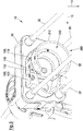
- Fig. 2 shows the clamping arrangement 22 with the housing 50 and the receptacle 100 extending through the opening 54 of the housing 50.
- the receptacle 100 is configured to receive cartridges having two separate compartments.
- the receptacle 100 has a first part 110 for receiving a first compartment and a separate second part 120 for receiving a second compartment of the cartridges.
- the first part 110 and the second part 120 each comprise a locating element 114 that extends through the opening 54 of the housing 50.
- Each locating element 114 comprises a cavity 136 at its front surface 130 for receiving the rear end of one of the compartments of the cartridges.
- a piston actuator opening 131 is located through which the piston actuators for moving the pistons of the cartridges may extend.
- the first part 110 of the receptacle 100 is longitudinally guided by the first rods 30 and the second part 120 is longitudinally guided by the second rods 32.
- the first part 110 has two first sleeves 112, each first sleeve 112 encompassing one of the first rods 30.
- the second part 120 has two second sleeves 122, each second sleeve 122 encompassing one of the second rods 32.
- Each individual sleeve 112, 122 extends through a separate opening in the front plate 52 of the housing 50.
- the first and the second part 110, 120 each have an attachment structure 140 for attaching adapters to the receptacle 100.
- the attachment structure 140 of the first part 110 is configured as a rotating bayonet fitting 146 and the attachment structure 140 of the second part 120 is configured as a clip-in connection.
- the clip-in connection has a lateral pocket 142 and a lateral stop 144 that are located opposite to each other in a lateral plane spanned by the first and second lateral directions 13, 14. In particular, the lateral pocket 142 and the lateral stop 144 are located opposite to each other in the further lateral direction 14.
- Fig. 3 shows a first adapter 300 attached to the first part 110 of the receptacle 100.
- the first adapter 300 comprises a locating element 312, which has an additional cavity 316 at its front surface.
- the additional cavity 136 is configured to receive the rear ends of cartridges inserted into the cartridge holder 10.
- the additional cavity 316 of the first adapter 300 has a larger extension in the lateral directions 13, 14 than the cavity 114 of the first part 110 of the receptacle 100.
- the first adapter 300 may be fitted to the rotating bayonet fitting 146 by rotating it around its longitudinal axis. While Fig. 3 shows the first adapter 300 in its locked position, Fig. 4 shows the first adapter 300 in an unlocked position in which it may be removed from the receptacle 100. The first adapter 300 is transferred from the locked position into the unlocked position by rotating it by about 60° around its longitudinal axis.
- Fig. 5 shows a second adapter 301 that is attachable to the attachment structure 114 of the second part 120 of the receptacle 100.
- the second adapter 301 comprises an additional cavity 316 that is formed at a front surface of a locating element 312 of the second adapter 301.
- the locating element 312 of the second adapter 301 is situated at a back plate 320 of the second adapter 301.
- the back plate 320 has a lateral ridge 318 extending from the locating element 312 in the lateral plane and a lateral notch 319 that is positioned opposite of the lateral ridge 318 in the lateral plane.
- the lateral ridge 318 when attaching the second adapter 301 to the second part 120 of the receptacle 100, the lateral ridge 318 is inserted into the lateral pocket 142 and the lateral notch 319 engages with the lateral stop 144 of the attachment structure 140 of the second part 120 of the receptacle 100.
- the lateral ridge 318 is first inserted into the lateral pocket 142 while keeping the back plate 320 of the second adapter 301 at an angle with the lateral plane defined by the lateral directions 13, 14. Subsequently, the lateral notch 119 is moved over the lateral stop 144 via the back plate 320 while transferring the back plate 320 into parallel alignment to the lateral plane.
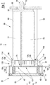
- Fig. 7 shows the cartridge holder 10 without the adapters 300, 301 when being equipped with a cartridge 60 of a first type.
- the cartridge 60 is placed between the distal plate 25 and the receptacle 100 of the clamping arrangement 22.
- the cartridge 60 has a first compartment 76 and a second compartment 77, each compartment 76, 77 having a circular cross-section in the transverse plane.
- the compartments 76, 77 lead into an outlet 74 at a dispensing end 73 of the cartridge 60.
- the first compartment 76 engages with the locating element 114 of the first part 110 of the receptacle 100 and the second compartment 77 engages with the locating element 114 of the second part 110 of the receptacle 100.
- Each locating element 114 has a radially tapered section 134 that is formed by an inner side wall 138 of the cavities 136 of the locating elements 114.
- the radially tapered sections 134 partly surround the rear end 75 of the compartments 76, 77.
- the cartridge holder 10 may be equipped with cartridges that contact the locating elements 114 at bottoms of the cavities 136 or at arbitrary positions along the inner sidewalls 138 of the cavities 136.
- a distance 107 between the rear end 75 of the cartridge 60 and a rear end 104 of the receptacle 100 amounts to a minimal possible distance and a separation 109 between the proximal end 20 of the cartridge holder 10 and the rear end 104 of the receptacle 100 amounts to a maximum possible distance.
- the additional cavities 316 of the first adapter 300 and the second adapter 301 form a common cavity receiving the cartridge 60.
- the two compartments 76, 77 of the cartridge 60 are connected with each other at their rear end 75 by a connecting element.
- the connecting element is placed inside the common cavity.
- the cartridge holder 10 may also be equipped with other types of cartridges that have a larger size in the lateral directions 13, 14 than the first type of cartridges 60.
- the other types of cartridges may have two compartments, each compartment having a larger diameter than the compartments 76, 77 of the first type of cartridges 60 shown in Fig. 7 .
- the receptacle 100 is configured to contact the rear end of the other types of cartridges at a larger distance from the rear end 104 of the receptacle 100 than the first type of cartridges 60.
- the rear ends of the cartridges contact the tapered side walls 138 in between the front surfaces 130 of the locating elements 114 and the bottom surfaces of the cavities 136.
- Fig. 7 also shows a first spring element 40 and a second spring element 42.
- the first spring element 40 surrounds the first rod 40 and spring-loads the first part 110 of the receptacle 100 towards the distal stop 25, while the second spring element 42 surrounds the second rod 32 and spring-loads the second part 120 of the receptacle 100 towards the distal stop 25.
- the spring elements 40, 42 are located inside the housing 50 and the housing 50 surrounds the parts 110, 120 of the receptacle 100 over their distance of travel 102 along the longitudinal axis 12.
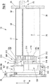
- Fig. 8 shows the cartridge holder 10 with the first adapter 300 and the second adapter 301 and equipped with a cartridge 61 of a second type.
- the cartridges 61 of the second type are configured as it is described and shown in connection with the cartridges 60 of the first type.
- the cartridges 61 of the second type have a smaller size along the longitudinal direction 12 than the cartridges 60 of the first type.
- the first compartment 76 of the second type of cartridges 61 has a larger diameter in the transverse plane than the first compartment 76 of the first type of cartridges 60 and the second compartment 77 of the second type of cartridges 61 has a smaller size in the transverse plane than the second compartment 77 of the first type of cartridges 60.
- Fitting the receptacle 100 with the first and second adapter 300, 301 allows using the cartridge holder 10 with the cartridge 61 of the second type irrespective of their shorter length along the longitudinal axis and different sizes in the transverse plane.
- the cartridge 61 is placed inside the additional cavities 316 of the adapters 300, 301 that together form a common cavity.
- the additional cavities 316 each have a tapered inner side wall 138 forming a radially tapered section 134 and the cartridge 61 contacts each adapter 300, 301 at the bottom of its respective additional cavity 316.
- the cartridge 61 of the second type contacts the receptacle 100, in particular its adapters 300, 301, at a greater distance 107 from the rear end of the receptacle 100. Additionally, the receptacle 100 is positioned farther away from the distal stop 25 when clamping the cartridge 61 of the second type instead of the cartridge 60 of the first type. Consequently, the separation 109 between the proximal end 20 of the cartridge holder 10 and the rear end 104 of the receptacle 100 is smaller when clamping the cartridge 61 of the second type than when clamping the cartridge 60 of the first type.
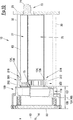
- Fig. 9 shows the cartridge holder 10 clamping a cartridge 62 of a third type.
- the cartridges 62 of the third type are configured as it is described and shown in connection with the cartridges 61 of the second type.
- the first compartment 76 of the cartridges 62 of the third type has a smaller diameter in the transverse plane and the second compartment 77 has a larger diameter in the transverse plane.
- the first part 110 of the receptacle 100 is equipped with a third adapter 302 and the second part 120 of the receptacle 100 is equipped with the second adapter 301.
- the third adapter 302 is configured as it is described and shown for the first adapter 301.
- the third adapter 302 has an additional cavity 316 having a smooth and radially tapered inner side wall 138 that forms a radially tapered section 134.
- the extension of the additional cavity 316 of the third adapter 302 in the transverse directions 13, 14 is smaller than the corresponding extension of the additional cavity 316 of the first adapter 300.
- a central longitudinal axis 314 of the locating element 312 of the third adapter 302 is shifted in the transverse direction 13 with respect to a central longitudinal axis 116 of the locating element 114 of the first part 110 of the receptacle 100.
- the position of the central longitudinal axis 314 of the locating element 312 in the lateral direction 13 is given by the center of the circular part of the additional cavity 316 of the locating element 312 and the position of the central longitudinal axis 116 of the locating element 114 in the lateral direction 13 is given by the center of the circular part of the cavity 136 of the first part 110 of the receptacle 100.
- the inner side wall 138 of the additional cavity 316 of the third adapter 302 contacts the rear end 75 of the first compartment 76 of the cartridge 62 and the inner side wall 138 of the second adapter 301 contacts the rear end 75 of the second compartment 77 of the cartridge 62.
- the first part 110 and the second part 120 of the receptacle 100 are independently movable along the longitudinal axis 12.
- the second element 120 of the receptacle 100 and the second adapter 301 are located farther away from the distal stop 25 then the first part 110 of the receptacle 100 with the third adapter 302.
- the rear end 104 of the receptacle 100 is in total defined by the rear end 106 of the second part 110 of the receptacle 100.
- the distance 107 between the rear end 104 of the receptacle 100 and the rear end 75 of the cartridge 62 of the third type is larger than the distance 107 between the rear end 104 of the receptacle 100 and the rear ends 75 of the cartridges 60, 61 of the first and second type.
- Fig. 10 shows the cartridge holder 10 clamping a cartridge 63 of a fourth type.
- the cartridges 63 of the fourth type are configured as it is described and shown in connection with the cartridges 61 of the second type.
- the first compartment 76 of the cartridges 63 of the fourth type has a smaller diameter in the transverse plane, while the diameters of the second compartments 77 are equal.
- the first part 110 of the receptacle 100 is equipped with the third adapter 302 and the second part 120 of the receptacle 100 is equipped with the second adapter 301.
- Each adapter 301, 302 contacts the rear end 75 of the cartridge 63 of the fourth type at the bottom of its additional cavity 316.
- the adapter for the first part 110 of the receptacle 100 and the adapter for the second part 120 of the receptacle 100 may in general have different thicknesses of the bottom sections of their respective additional cavities 316.
- the third adapter 302 has an additional cavity 316 with a bottom section that has a greater thickness than the second adapter 301.
- the third adapter 302 and the first part 110 of the receptacle 100 are located farther away from the distal stop 25 than the second adapter 301 and the second part 120 of the receptacle 100. Consequently, the distance 107 between the rear end 75 of the cartridge 63 of the fourth type and the rear end 104 of the receptacle 100 is defined by the distance between a rear end 105 of the first part 110 of the receptacle 100 and the rear end 75 of the cartridge 63.
- the distance 107 between the rear end 75 of the cartridge 63 and the rear end 107 of the receptacle 100 is larger than with the cartridges 60, 61 of the first and second type, but smaller than with the cartridge 62 of the third type.
- Fig. 11 shows the cartridge holder 10 clamping a cartridge 64 of a fifth type.
- the cartridges 64 of the fifth type are configured as it is described and shown in connection with the cartridges 64 of the fourth type.
- the cartridge 64 of the fifth type has a second compartment 77 with a smaller diameter in the transverse plane, and a first compartment 76 with a larger diameter in the transverse plane.
- the first part 110 of the receptacle 100 is equipped with the third adapter 302 and the second part 120 of the receptacle 100 is equipped with a fourth adapter 303.
- Each adapter 302, 303 contacts the rear end 75 of the cartridge 64 of the fifth type at the tapered inner side wall 138 of its additional cavity 316.
- the first part 110 of the receptacle 100 with the third adapter 302 is positioned farther away from the distal stop 25 than the second part 120 of the receptacle 100 with the fourth adapter 303.
- the rear end 104 of the receptacle 100 is then given by the rear end 105 of the first part 110 of the receptacle 100.
- the distance 107 between the rear end 104 of the receptacle 100 and the rear and 105 of the cartridge 64 is larger than with the cartridge 63 of the fourth type and smaller than with the cartridge 62 of the third type.
- Fig. 12 shows the cartridge holder 10 according to an alternative embodiment.
- the cartridge holder 10 according to the alternative embodiment has a receptacle 100 with a first part 110 and a separate second part 120, whereby the first part 110 is longitudinally guided by a pair of first rods 30 and the second part 120 is longitudinally guided by a pair of second rods 32.
- the first part 110 and the second part 120 of the receptacle 100 are independently movable along the longitudinal axis 12.
- Each part 110, 120 is spring loaded towards the distal stop (not shown) of the cartridge holder 10 by spring elements, but only one spring element 42 is shown in Fig. 12 .
- the first and second parts 110, 120 of the receptacle 100 are configured as plate-like structures that extend perpendicular to the longitudinal axis 12.
- Locating elements 205 of the first and second parts 110, 112 of the receptacle 100 are configured as grooves that are positioned on the front sides 210 of the first and second parts 110, 120 of the receptacle 100.
- the grooves have a circular shape with different diameters in the transverse plane and are positioned eccentrically to each other so that they touch near those edges of the first and second parts 110, 120 that face each other.
- the first and second parts 110, 112 of the receptacle 100 each comprise an attachment structure 140 for receiving additional adapters 305 as shown in Fig. 13 .
- Each additional adapter 305 is configured as a plate-like structure and has further locating elements 206 positioned on its front side facing the distal stop of the cartridge holder 10.
- the further locating elements 206 of the additional adapters 305 are configured as eccentric circular grooves.
- the attachment structures 140 are configured as orthogonal ridges that are located at the front sides of the respective part 110, 112 of the receptacle 100 and form notches that encompass the additional adapters 305 at two lateral sides.
- the second embodiment of the cartridge holder 10 is configured to be fitted with a first type of cartridges, wherein the rear ends of the cartridges are received by the locating elements 205 formed in the first and second part 110, 112 of the receptacle 100.
- the cartridge holder 10 is configured to be fitted with a second type of cartridges, wherein the rear ends of the cartridges are received by the further locating elements 206 formed in the additional adapters 305.
- the first and second types of cartridges may have different sizes in the longitudinal direction 12 and/or in the transverse plane perpendicular to the longitudinal direction 12.
- Fig. 14 shows an alternative embodiment of the cartridge holder 10.
- the cartridge holder 10 according to the alternative embodiment may be configured as it is described and shown in connection with the embodiment of the cartridge holder 10 shown in Figs. 1 to 11 .
- the locating elements 114 are laterally connected with the sleeves 112, 122 that guide the individual parts 110, 120 of the receptacle 100 along the longitudinal rods 30, 32. Lateral connection between the locating elements 114 and the sleeves 112, 122 is established by individual connection structures 113 that connect the locating elements 114 and the sleeves 112, 122.
- the locating elements 114 and the sleeves 112, 122 are structurally and integrally connected with each other, in particular, they may be configured, for example molded or casted, as a common and material-uniform component.
- the connection structures 113 extend along the longitudinal axis into the housing 50 of the clamping arrangement 22 shown in Fig. 14 . Thereby, the openings 54 in the front plate 52 of the housing 50 also encompass the connection structures 113.
- both the attachment structure 140 of the first part 110 of the receptacle 100 and the attachment structure 140 of the second part 120 of the receptacle 100 are configured to receive adapters that are rotatable attachable to the individual attachment structures 140.
- the attachment structures 140 of both the first and second part 110, 120 of the receptacle 100 are configured as rotating bayonet fittings 146.
- the attachment structure 140 of the first part 110 of the receptacle 100 may be equipped with the first adapter 300 or the third adapter 302 already described in connection with the cartridge holder 10 shown in Figs. 1 to 11 .
- the attachment structure 140 of the second part 120 of the receptacle 100 may be equipped with a sixth adapter 306 that is shown in Fig. 15 .
- the sixth adapter 306 is rotatable attachable to the attachment structure 140 of the second part 120 of the receptacle 100.
- the sixth adapter 306 is configured as described in connection with the second and fourth adapters 301, 303.
- the back plate 320 of the sixth adapter 306 has a lateral connection structure that comprises at least one lateral protrusion 322, in particular three lateral protrusions 322.
- the lateral protrusions 322 are configured to engage with the rotating bayonet fitting 146 of the second part 120 of the receptacle 100 shown in Fig. 14 upon rotation of the sixth adapter 306 around its longitudinal axis.
- Fig. 16 shows the alternative embodiment of the cartridge holder 10 with the first adapter 300 attached to the first part 110 of the receptacle 100.
- the locating element 312 of the first adapter 300 has a lateral cutout 313 that is placed next to the second part 120 of the receptacle 100, when the first adapter 300 is attached to the first part 110 of the receptacle 100.
- the lateral cutout 313 allows the sixth adapter 306 to protrude into the cavity 316 of the locating element 312 of the first adapter 300 when the sixth adapter 306 is inserted into the attachment structure 140 of the second part 120 of the receptacle 100.
- Fig. 17 shows the dispenser 1 equipped with the alternative embodiment of the cartridge holder 10.
- the first adapter 300 is attached to the first part 110 of the receptacle 100 and the sixth adapter 306 is attached to the second part 120 of the receptacle 100.
- the cartridge holder 10 has been described as having at least one attachment structure 114 that is configured as rotating bayonet fitting 146.
- all attachment structures 140 in particular the attachment structures 140 of both the first part 110 and the second part 120 of the receptacle 100, may be configured as clip-in connections, for example having the lateral pocket 142 and the lateral stop 144 of the attachment structure 140 of the second part 120 of the receptacle 100 shown in Figs. 1 to 11 .
- the attachement structure 140 of the first part 110 of the receptacle may be configured as the described clip-in connection and the attachment structure 140 of the second part 120 of the receptacle 100 may be configured to have the adapter rotatable attached, in particular by being configured as a rotating bayonet fitting.
- the structural connection between the sleeves 112, 122 and the locating elements 114 may be independently realized from the configuration of the attachment structures 140 of the individual parts 110, 120 of the receptacle.
- the embodiment of the cartridge holder 10 shown Figs. 1 to 11 may comprise the structural connection between the sleeves 112, 122 and the locating elements 114 and the embodiment of the cartridge holder 10 shown in Figs. 14 to 17 may be configured without said structural connection.
Landscapes
- Engineering & Computer Science (AREA)
- Mechanical Engineering (AREA)
- Coating Apparatus (AREA)
- Containers And Packaging Bodies Having A Special Means To Remove Contents (AREA)
- Infusion, Injection, And Reservoir Apparatuses (AREA)
Abstract
A cartridge holder (10) for a dispenser (1) dispensing viscous material is configured to alternately receive at least a first type of cartridges and a second type of cartridges containing the viscous material. The cartridges of the first type are different in size from the cartridges of the second type. The cartridge holder has a distal stop (25) for receiving a dispensing end of the cartridges and a proximal receptacle (100) for receiving a rear end of the cartridges. The receptacle is located opposite to the distal stop along a longitudinal axis of the cartridge holder and is movable along the longitudinal axis as well as spring-loaded towards the distal stop. Furthermore, the receptacle is configured to contact the rear end of the first type of cartridges at a smaller distance from a rear end of the receptacle than the rear end of the second type of cartridges.
Description
- The present disclosure relates to cartridge holders for dispensers for dispensing viscous material.
- Dispensers for dispensing viscous materials are used in various technical areas, such as construction engineering, medical, or dental technology, to dispense, for example, viscous adhesives, filling material or sealing compounds. Said dispensers usually comprise a cartridge holder for receiving a cartridge containing the viscous material and actuating means for moving one or more pistons to urge the viscous material out of the cartridge.
- It is usually desirable that, after inserting the cartridge into the cartridge holder of the dispenser, the cartridge is firmly held into place to allow using the dispenser in arbitrary orientations such as upside-down or vertical orientation. To prevent the cartridge from falling out of the cartridge holder, the cartridge may be longitudinally clamped inside the cartridge holder, for example by one or more flexible elements. One prerequisite for clamping the cartridge inside the cartridge holder is that the clamping element firmly engages the cartridge in order to prevent lateral movement perpendicular to the clamping direction. This usually necessitates clamping elements that specifically match the size of the cartridges so that it is not possible to use various types of cartridges with a single dispenser.
- Accordingly, there is a need to provide cartridge holders and dispensers that are configured to receive various types of cartridges and simultaneously provide for reliable clamping of the cartridges.
- The present disclosure provides cartridge holders and a dispenser according to the independent claims. Embodiments are given in the subclaims, the description and the drawings.
- In one aspect, the present disclosure is directed at a cartridge holder for a dispenser, wherein the cartridge holder is configured to alternately receive at least a first type of cartridges and a second type of cartridges containing the viscous material. The cartridges of the first type are different in size from the cartridges of the second type. The cartridge holder has a distal stop for receiving a dispensing end of the cartridges and a proximal receptacle for receiving a rear end of the cartridges. The receptacle is located opposite to the distal stop along a longitudinal axis of the cartridge holder and is movable along the longitudinal axis as well as spring-loaded towards the distal stop. Furthermore, the receptacle is configured to contact the rear end of the first type of cartridges at a smaller distance from a rear end of the receptacle than the rear end of the second type of cartridges.
- Since the receptacle contacts the rear end of different types of cartridges at different distances from its rear end, the shape of the receptacle may exhibit longitudinal variations that allow adaption to cartridges of different sizes. Such longitudinal variations may comprise radially tapered sections that accommodate cartridges of different diameter or adapters that are attachable to the front side of the receptacle. Movement of the receptacle along the longitudinal axis then may serve not only for clamping the cartridge, but also for adapting the cartridge holder to different cartridge sizes. Thereby, the different types of cartridges may vary in size along the radial direction and/or along the longitudinal direction.
- The receptacle according to the present disclosure therefore adapts in two ways to cartridges of different sizes. First, it may be positioned in its entirety at various positions along its distance of travel along the longitudinal axis. Second, it may receive the cartridges at various distances from its own rear end. If the two types of cartridges both have the same length in the longitudinal direction, receiving the different types of cartridges at different distances from the rear and of the receptacle usually means that the receptacle is placed at different positions along the longitudinal axis when clamping the different types of cartridges.
- The receptacle may be configured to receive cartridges having a single compartment. Alternatively, or additionally, it may be configured to receive cartridges having several compartments, in particular two separate compartments. The compartments may be positioned next to each other in a lateral direction perpendicular to the longitudinal axis. The first type of cartridges and the second type of cartridges may comprise compartments with different diameters in the lateral direction. Additionally, or alternatively, the compartments may exhibit different lengths in the longitudinal direction.
- The receptacle may have a single part that is only movable along the longitudinal axis in its entirety. It also may have two or more separate parts, each part being movable individually along the longitudinal axis. The individual parts may be configured to each receive a rear end of separate compartments of the cartridges.
- The receptacle may be configured to receive the different types of cartridges at varying distances from its rear end by having a locating element that is integrally connected with a base element of the receptacle and receives the rear end of the cartridges. The locating element may have a radially tapered section extending in the longitudinal direction. The receptacle may also be configured to receive the different types of cartridges at varying distances from its rear end by being fitted with different types of adapters, each adapter having a locating element. The individual locating elements of the adapters may contact the rear ends of the cartridges at different distances from the rear end of the receptacle. The adapters may be configured to be alternately attachable to a base element of the receptacle or to a locating element that is provided at the base element.
- The cartridges may comprise one or more pistons, each piston urging the viscous material out of the individual compartments at the dispensing end of the cartridges when moving the pistons towards the dispensing end of the cartridges. The dispenser may comprise one or more piston actuators that are movable along the longitudinal direction and are configured to engage with the one or more pistons of the cartridges to move the pistons in the longitudinal direction towards the dispensing end of the cartridges. The piston actuators each may comprise a rod and preferably a plunger arranged at a distal end of the rod.
- The receptacle receiving the rear end of the cartridges may have one or more piston actuator openings, whereby each piston actuator opening provides a longitudinal passage through the receptacle for one or more piston actuators. In particular, the receptacle may encompass the piston actuators. The piston actuators openings allow the piston actuators to extend through the receptacle to engage with the pistons of the cartridges while the receptacle itself may remain at its position along the longitudinal axis to firmly hold the cartridge in place. The dispenser may be a manual dispenser having a manual piston actuating device for moving the piston actuators, a motorized dispenser having a motorized piston actuator device, or a pneumatic dispenser having a piston actuator device that can be driven by a pressurized gas, for example air.
- According to an embodiment, the receptacle comprises a locating element having a radially tapered section that is configured to at least partly circumferentially surround, for example engage, the rear end of the cartridge. The radially tapered section may extend along the longitudinal axis, so that the radial dimensions of the tapered section vary along the longitudinal axis, for example narrow with increasing distance from the distal stop of the cartridge holder.
- The locating element may contact the rear end of cartridges that have different sizes in the lateral or radial direction at different longitudinal locations along its tapered section. Additionally, the radially tapered section may serve to center the cartridges in the radial direction at a longitudinal axis of the locating element and thus to prohibit lateral shifting or skewing of the cartridges after insertion into the cartridge holder. The longitudinal axis of the locating element may be parallel to the longitudinal axis of the cartridge holder. It may be shifted with respect to the longitudinal axis of the cartridge holder, for example in the radial direction. The radially tapered section also allows for adaption to varying sizes of the cartridges in the radial direction that may, for example, result from manufacturing tolerances. The laterally tapered section may surround or engage the rear end of the cartridge at least over a quarter, a third or a half of its circumference.
- According to an embodiment, the radially tapered section is configured as a tapered inner side wall of a cavity formed at a front surface of the locating element, said front surface facing the distal stop of the cartridge holder. The cavity may be configured to receive the rear end of the cartridges. It may have an at least partially circular cross-section. At the bottom of the cavity, the piston actuator opening may be provided so that the piston actuator may extend through the cavity into the cartridge.
- According to an embodiment, the tapered section has a smooth surface, for example a smooth and at least partly conical surface. In particular, the taper may be free of steps or edges. This allows for continuous adaption to and exact centering of cartridges with varying sizes in the radial direction.
- According to an alternative embodiment, the tapered section has a stepped surface, for example a stepped and at least partly conical surface. The steps may provide bearing surfaces which the rear ends of the cartridges may lay against and may provide robust support for the cartridges in the longitudinal direction. The bearing surfaces may be oriented perpendicular to the longitudinal axis.
- According to an embodiment, the cartridge holder comprises an adapter that is attachable to the receptacle via an attachment structure. The receptacle comprises a first locating element that is configured to contact the rear end of the first type of cartridges and the adapter comprises a second locating element that is configured to contact the rear end of the second type of cartridges. Said adapter allows the receptacle to be adapted to different sizes of cartridges over a wide range. The adapter may allow the receptacle to be adapted to cartridges having different sizes in the lateral and/or longitudinal direction. The attachment structure may, for example, be positioned at the first locating element. The first locating element and/or the second locating element may be configured in the same way as it is described for the locating element mentioned above. In particular, the first locating element and/or the second locating element may comprise said radially tapered section.
- According to an embodiment, the attachment structure is located at a front surface of the first locating element of the receptacle. Thereby, the adapter may be positioned between the receptacle and the distal stop of the cartridge holder and the adapter may serve to reduce the spacing between the distal stop and the locating element receiving the rear and of the cartridges. In particular, the adapter may cover the first locating element upon attachment to the receptacle.
- According to an embodiment, the attachment structure allows for releasable connection of the adapter to the receptacle. Such an attachment structure allows for variable fitting of the receptacle with the adapter.
- According to an embodiment, the attachment structure is configured as a clip-in connection. For example, the clip-in connection may allow the adapter being inserted under an angle with respect to a lateral plane that is oriented perpendicular to the longitudinal axis and may prevent lateral movement of the adapter along the lateral plane after insertion. Such a clip-in connection provides a reliable and easy-to-use interface for the adapter.
- According to an embodiment, the attachment structure has a lateral pocket that is configured to receive a lateral ridge of the adapter and a lateral stop that is located opposite of the pocket in the lateral direction and that is configured to limit lateral movement of the adapter after insertion of the ridge into the pocket. The adapter may comprise a recess, for example a notch, for receiving the lateral stop of the attachment structure.
- According to an embodiment, the adapter is rotatable attachable to the attachment structure, for example upon rotation about its longitudinal axis. Such an attachment structure may comprise a threaded element, for example an inner or outer thread, positioned at the receptacle.
- According to an embodiment, the attachment structure is configured as a rotating bayonet fitting. This allows easy attachment of the adapter without the need to turn the adapter several times around its longitudinal axis. The rotating bayonet fitting may be configured to receive the adapter upon rotation by at most 120°, for example at most 90°, 60° or 40° and/or by at least 10°, for example at least 20° or at least 40°.
- According to an embodiment, a central longitudinal axis of the second locating element of the attached adapter is laterally shifted with respect to a central longitudinal axis of the first locating element. This allows to center cartridges or individual compartments of the cartridges of the first and second type at different positions in the lateral direction. If the cartridges are, for example, configured as two-compartment cartridges, centering the individual compartments of the cartridges at different positions in the lateral direction allows to align the dispensing end of the cartridge, for example an outlet of the cartridges, with the distal stop irrespective of the size of the individual compartments.
- According to an embodiment, the first locating element has a first cavity for receiving the rear end of the first type of cartridges and the second locating element has a second cavity for receiving the rear end of the second type of cartridges, wherein the second cavity has a smaller extension perpendicular to the longitudinal axis than the first cavity. The first and second cavity may be configured as described in connection with the cavity mentioned above. For example, the first and/or second cavity may comprise a tapered inner side wall.
- According to an embodiment, the receptacle comprises a first part for receiving a rear end of a first compartment of a two-component cartridge and a separate second part for receiving a rear end of a second compartment of the two-component cartridge, wherein the first part and the second part are placed next to each other in a lateral direction that is perpendicular to the longitudinal axis and are independently movable along the longitudinal axis.
- Being movable independently from each other along the longitudinal axis, the first and second part of the receptacle may individually adapt to cartridges having compartments of different sizes in the longitudinal and/or lateral direction. The individual parts of the receptacle may each comprise the locating element that has been described above. Additionally, or alternatively, the individual parts may each comprise the attachment structure that has been described above.
- According to an embodiment, the first part and the second part form a common cavity for receiving the rear ends of the first and second type of cartridges. This allows for a secure fixation of the cartridges in the cartridge holder. Furthermore, the compartments of the cartridges may be connected together in an interspace between the compartments and the connecting structure may be received inside the common cavity.
- According to an embodiment, the cartridge holder comprises at least one first longitudinal rod and at least one second longitudinal rod, wherein the first part is longitudinally guided by the at least one first longitudinal rod and the second part is longitudinally guided by the at least one second longitudinal rod. Thereby, the longitudinal rods extend between a proximal end of the cartridge holder and the distal stop. The first part may, for example, encompass the at least one first rod, but not the at least one second rod, and/or the second part may encompass the at least one second rod, but not the at least one first rod. The longitudinal rods may additionally join the distal stop and the proximal end of the cartridge holder.
- According to an embodiment, at least one first spring element spring-loading the first part is located around one of the first longitudinal rods and at least one second spring element spring-loading the second part is located around one of the second longitudinal rods. The spring elements may individually bias the first and second part of the receptacle towards the distal stop of the cartridge holder.
- According to an embodiment, the cartridge holder comprises a housing surrounding a distance of travel along which the receptacle is longitudinally movable. This prevents any objects from blocking the distance of travel and minimizes potential injuries of a user of the dispenser.
- According to an embodiment, the housing has a front plate with an opening, wherein a portion of the receptacle that is configured to contact the rear end of the cartridges extends through the opening. This facilitates insertion of the cartridges into the receptacle. The opening may additionally provide guidance of the receptacle in the longitudinal direction. The portion of the receptacle that extends through the opening may, for example, be at least a part of the locating element.
- In another aspect, the present disclosure is directed at a cartridge holder for a dispenser, the cartridge holder being configured to alternately receive at least a first type of two-component cartridges and a second type of two-component cartridges containing viscous material. The cartridges of the first type are different in size from the cartridges of the second type. The cartridge holder has a distal stop for receiving a dispensing end of the cartridges and a proximal receptacle for receiving a rear end of the cartridges. The receptacle is located opposite to the distal stop along a longitudinal axis of the cartridge holder, while the receptacle is movable along the longitudinal axis and spring-loaded towards the distal stop. The receptacle comprises a first part and a separate second part, wherein the first part is configured to receive a rear end of a first compartment of the two-component cartridges and the separate second part is configured to receive a rear end of a second compartment of the two-component cartridges. The first part and the second part are placed next to each other in a lateral direction that is perpendicular to the longitudinal axis and are independently movable along the longitudinal axis.
- Said cartridge holder solves the problem to receive various types of cartridges and simultaneously provide for reliable clamping of the cartridges by having a receptacle with two separate and independently movable parts. This allows for insertion of different types of cartridges that have compartments with varying lengths in the longitudinal direction. In particular, the cartridges may have compartments with unequal sizes in the longitudinal direction and a length difference between the compartments in the longitudinal direction may vary across the different type of cartridges. For example, one type of cartridges may have compartments with a first length difference in the longitudinal direction and another type of cartridges may have compartments with a second length difference that differs from the first length difference.
- The first part and/or the second part may comprise the locating element and/or the attachment structure described above. Insofar, all technical effects and embodiments of the locating element and/or the attachment structure described above also apply to the receptacle having two separate parts.
- In another aspect, the present disclosure is directed at a dispenser for dispensing viscous material having the cartridge holder described above. Insofar, all technical effects and embodiments of the cartridge holder described above also apply to the dispenser.
- Exemplary embodiments and functions of the present disclosure are described herein in conjunction with the following drawings, showing schematically:
- Fig. 1
- a dispenser having a cartridge holder;
- Fig. 2
- a clamping arrangement of the cartridge holder with an receptacle;
- Fig. 3
- the receptacle with a first adapter attached;
- Fig. 4
- the receptacle with the first adapter positioned in an insertion orientation;
- Fig. 5
- a second adapter for the receptacle;
- Fig. 6
- the receptacle with the first adapter and the second adapter attached;
- Fig. 7
- a cross-sectional view of the cartridge holder with an inserted cartridge of a first type;
- Fig. 8
- a cross-sectional view of the cartridge holder with the first and second adapter attached and an inserted cartridge of a second type;
- Fig. 9
- a cross-sectional view of the cartridge holder with the second adapter and a third adapter attached and an inserted cartridge of a third type;
- Fig. 10
- a cross-sectional view of the cartridge holder with the second and third adapter attached and an inserted cartridge of a fourth type;
- Fig. 11
- a cross-sectional view of the cartridge holder with the third adapter and a fourth adapter attached and an inserted cartridge of a fifth type;
- Fig. 12
- the cartridge holder according to an alternative embodiment;
- Fig. 13
- the cartridge holder according to the alternative embodiment with two additional adapters;
- Fig. 14
- the cartridge holder according to another alternative embodiment;
- Fig. 15
- a sixth adapter that is connectable to a receptacle of the alternative embodiment of the cartridge holder;
- Fig. 16
- the alternative embodiment of the cartridge holder with the first adapter attached to a receptacle of the cartridge holder; and
- Fig. 17
- the alternative embodiment of the cartridge holder with the first adapter and a sixth adapter attached to the receptacle.
-
Fig. 1 depicts a dispenser 1 having acartridge holder 10 and apiston actuating device 3. Thecartridge holder 10 is configured to hold varying types of cartridges containing viscous material. Thecartridge holder 10 has adistal stop 25 and a clampingarrangement 22. The clampingarrangement 22 is located at aproximal end 20 of thecartridge holder 10 and thedistal stop 25 is located opposite to the clampingarrangement 22 along alongitudinal axis 12 of thecartridge holder 10. Thedistal stop 25 and the clampingarrangement 22 are longitudinally connected by two firstlongitudinal rods 30 and two secondlongitudinal rods 32. The secondlongitudinal rods 32 are located opposite to the firstlongitudinal rods 30 with respect to alateral direction 13, whereby thelateral direction 13 is orientated perpendicular to thelongitudinal axis 12. - The
cartridge holder 10 is configured to receive the cartridges containing the viscous material in the space between thedistal stop 25 and the clampingarrangement 22. Thedistal stop 25 has acartridge support 26 for receiving a dispensing end of the cartridges, whereby thecartridge support 26 is configured as a radial notch extending along a furtherlateral direction 14 that is orientated perpendicular to thelongitudinal axis 12 and thelateral direction 13. The clampingarrangement 22 comprises areceptacle 100 that is movable along thelongitudinal axis 12 and is configured to receive a rear end of the cartridges. Upon insertion, the rear end of the cartridges is placed in thereceptacle 100 and thereceptacle 100 is moved together with the cartridge away from thedistal stop 25 against a restoring force exerted by spring elements (not shown) of the clampingarrangement 22. Subsequently, an outlet of the cartridge that is located at its dispensing end is inserted into thecartridge support 26. After releasing the cartridge, it is clamped towards thedistal stop 25 by the spring force of the spring elements. - The clamping
arrangement 22 comprises ahousing 50 that is covered by afront plate 52 at its front side facing thedistal stop 25. Thereceptacle 100 is placed inside thehousing 50 and extends through anopening 54 in thefront plate 52 of thehousing 50. - The
piston actuating device 3 is configured as a motorized actuating device. It is configured to move two piston actuators (not shown) towards thedistal stops 25 and to thereby urge the viscous material out of the cartridge. The piston actuators are configured as longitudinal rods that have toothed portions that are connected to an electric motor of theactuating device 3. -
Fig. 2 shows the clampingarrangement 22 with thehousing 50 and thereceptacle 100 extending through theopening 54 of thehousing 50. Thereceptacle 100 is configured to receive cartridges having two separate compartments. Thereceptacle 100 has afirst part 110 for receiving a first compartment and a separatesecond part 120 for receiving a second compartment of the cartridges. Thefirst part 110 and thesecond part 120 each comprise a locatingelement 114 that extends through theopening 54 of thehousing 50. Each locatingelement 114 comprises acavity 136 at itsfront surface 130 for receiving the rear end of one of the compartments of the cartridges. At the bottom of eachcavity 136, apiston actuator opening 131 is located through which the piston actuators for moving the pistons of the cartridges may extend. - The
first part 110 of thereceptacle 100 is longitudinally guided by thefirst rods 30 and thesecond part 120 is longitudinally guided by thesecond rods 32. Thefirst part 110 has twofirst sleeves 112, eachfirst sleeve 112 encompassing one of thefirst rods 30. Analogously, thesecond part 120 has twosecond sleeves 122, eachsecond sleeve 122 encompassing one of thesecond rods 32. Eachindividual sleeve front plate 52 of thehousing 50. - At the
front side 130, the first and thesecond part attachment structure 140 for attaching adapters to thereceptacle 100. Theattachment structure 140 of thefirst part 110 is configured as a rotating bayonet fitting 146 and theattachment structure 140 of thesecond part 120 is configured as a clip-in connection. The clip-in connection has alateral pocket 142 and alateral stop 144 that are located opposite to each other in a lateral plane spanned by the first and secondlateral directions lateral pocket 142 and thelateral stop 144 are located opposite to each other in the furtherlateral direction 14. -
Fig. 3 shows afirst adapter 300 attached to thefirst part 110 of thereceptacle 100. Thefirst adapter 300 comprises a locatingelement 312, which has anadditional cavity 316 at its front surface. Like thecavity 114 of the locatingelement 114 of thefirst part 110 of thereceptacle 100, theadditional cavity 136 is configured to receive the rear ends of cartridges inserted into thecartridge holder 10. Theadditional cavity 316 of thefirst adapter 300 has a larger extension in thelateral directions cavity 114 of thefirst part 110 of thereceptacle 100. - The
first adapter 300 may be fitted to the rotating bayonet fitting 146 by rotating it around its longitudinal axis. WhileFig. 3 shows thefirst adapter 300 in its locked position,Fig. 4 shows thefirst adapter 300 in an unlocked position in which it may be removed from thereceptacle 100. Thefirst adapter 300 is transferred from the locked position into the unlocked position by rotating it by about 60° around its longitudinal axis. -
Fig. 5 shows asecond adapter 301 that is attachable to theattachment structure 114 of thesecond part 120 of thereceptacle 100. Like thefirst adapter 300, thesecond adapter 301 comprises anadditional cavity 316 that is formed at a front surface of a locatingelement 312 of thesecond adapter 301. The locatingelement 312 of thesecond adapter 301 is situated at aback plate 320 of thesecond adapter 301. Theback plate 320 has alateral ridge 318 extending from the locatingelement 312 in the lateral plane and alateral notch 319 that is positioned opposite of thelateral ridge 318 in the lateral plane. - As can the seen from
Fig. 6 , when attaching thesecond adapter 301 to thesecond part 120 of thereceptacle 100, thelateral ridge 318 is inserted into thelateral pocket 142 and thelateral notch 319 engages with thelateral stop 144 of theattachment structure 140 of thesecond part 120 of thereceptacle 100. Upon attachment of thesecond adapter 301, thelateral ridge 318 is first inserted into thelateral pocket 142 while keeping theback plate 320 of thesecond adapter 301 at an angle with the lateral plane defined by thelateral directions lateral stop 144 via theback plate 320 while transferring theback plate 320 into parallel alignment to the lateral plane. -
Fig. 7 shows thecartridge holder 10 without theadapters cartridge 60 of a first type. Thecartridge 60 is placed between thedistal plate 25 and thereceptacle 100 of the clampingarrangement 22. Thecartridge 60 has afirst compartment 76 and asecond compartment 77, eachcompartment compartments outlet 74 at a dispensingend 73 of thecartridge 60. At theirrear end 75 opposite to the dispensingend 73, thefirst compartment 76 engages with the locatingelement 114 of thefirst part 110 of thereceptacle 100 and thesecond compartment 77 engages with the locatingelement 114 of thesecond part 110 of thereceptacle 100. - Each locating
element 114 has a radially taperedsection 134 that is formed by aninner side wall 138 of thecavities 136 of the locatingelements 114. The radially taperedsections 134 partly surround therear end 75 of thecompartments cartridge holder 10 may be equipped with cartridges that contact the locatingelements 114 at bottoms of thecavities 136 or at arbitrary positions along theinner sidewalls 138 of thecavities 136. Since thecartridge 60 contacts the locatingelements 114 at the bottom of thecavities 136, adistance 107 between therear end 75 of thecartridge 60 and arear end 104 of thereceptacle 100 amounts to a minimal possible distance and aseparation 109 between theproximal end 20 of thecartridge holder 10 and therear end 104 of thereceptacle 100 amounts to a maximum possible distance. - As can be seen from
Fig. 7 , theadditional cavities 316 of thefirst adapter 300 and thesecond adapter 301 form a common cavity receiving thecartridge 60. The twocompartments cartridge 60 are connected with each other at theirrear end 75 by a connecting element. When inserting thecartridge 60 into thecartridge holder 10, the connecting element is placed inside the common cavity. - The
cartridge holder 10 may also be equipped with other types of cartridges that have a larger size in thelateral directions cartridges 60. In particular, the other types of cartridges may have two compartments, each compartment having a larger diameter than thecompartments cartridges 60 shown inFig. 7 . By havingcavities 136 with taperedinner side walls 138, thereceptacle 100 is configured to contact the rear end of the other types of cartridges at a larger distance from therear end 104 of thereceptacle 100 than the first type ofcartridges 60. When equipping thecartridge holder 10 with the other types of cartridges, the rear ends of the cartridges contact the taperedside walls 138 in between thefront surfaces 130 of the locatingelements 114 and the bottom surfaces of thecavities 136. -
Fig. 7 also shows afirst spring element 40 and asecond spring element 42. Thefirst spring element 40 surrounds thefirst rod 40 and spring-loads thefirst part 110 of thereceptacle 100 towards thedistal stop 25, while thesecond spring element 42 surrounds thesecond rod 32 and spring-loads thesecond part 120 of thereceptacle 100 towards thedistal stop 25. Thespring elements housing 50 and thehousing 50 surrounds theparts receptacle 100 over their distance oftravel 102 along thelongitudinal axis 12. -
Fig. 8 shows thecartridge holder 10 with thefirst adapter 300 and thesecond adapter 301 and equipped with acartridge 61 of a second type. As far as no differences are apparent from the description or the drawings, thecartridges 61 of the second type are configured as it is described and shown in connection with thecartridges 60 of the first type. Thecartridges 61 of the second type have a smaller size along thelongitudinal direction 12 than thecartridges 60 of the first type. Additionally, thefirst compartment 76 of the second type ofcartridges 61 has a larger diameter in the transverse plane than thefirst compartment 76 of the first type ofcartridges 60 and thesecond compartment 77 of the second type ofcartridges 61 has a smaller size in the transverse plane than thesecond compartment 77 of the first type ofcartridges 60. - Fitting the
receptacle 100 with the first andsecond adapter cartridge holder 10 with thecartridge 61 of the second type irrespective of their shorter length along the longitudinal axis and different sizes in the transverse plane. Thecartridge 61 is placed inside theadditional cavities 316 of theadapters Fig. 8 , theadditional cavities 316 each have a taperedinner side wall 138 forming a radially taperedsection 134 and thecartridge 61 contacts eachadapter additional cavity 316. Compared to thecartridge 60 of the first type shown inFig. 7 , thecartridge 61 of the second type contacts thereceptacle 100, in particular itsadapters greater distance 107 from the rear end of thereceptacle 100. Additionally, thereceptacle 100 is positioned farther away from thedistal stop 25 when clamping thecartridge 61 of the second type instead of thecartridge 60 of the first type. Consequently, theseparation 109 between theproximal end 20 of thecartridge holder 10 and therear end 104 of thereceptacle 100 is smaller when clamping thecartridge 61 of the second type than when clamping thecartridge 60 of the first type. -
Fig. 9 shows thecartridge holder 10 clamping acartridge 62 of a third type. As far as no differences are apparent from the description or the drawings, thecartridges 62 of the third type are configured as it is described and shown in connection with thecartridges 61 of the second type. Compared with thecartridge 61 of the second type, thefirst compartment 76 of thecartridges 62 of the third type has a smaller diameter in the transverse plane and thesecond compartment 77 has a larger diameter in the transverse plane. - For clamping the
cartridge 62 of the third type, thefirst part 110 of thereceptacle 100 is equipped with athird adapter 302 and thesecond part 120 of thereceptacle 100 is equipped with thesecond adapter 301. As far as no differences follow from the description or the figures, thethird adapter 302 is configured as it is described and shown for thefirst adapter 301. Like thefirst adapter 301, thethird adapter 302 has anadditional cavity 316 having a smooth and radially taperedinner side wall 138 that forms a radially taperedsection 134. The extension of theadditional cavity 316 of thethird adapter 302 in thetransverse directions additional cavity 316 of thefirst adapter 300. Additionally, a centrallongitudinal axis 314 of the locatingelement 312 of thethird adapter 302 is shifted in thetransverse direction 13 with respect to a centrallongitudinal axis 116 of the locatingelement 114 of thefirst part 110 of thereceptacle 100. Thereby, the position of the centrallongitudinal axis 314 of the locatingelement 312 in thelateral direction 13 is given by the center of the circular part of theadditional cavity 316 of the locatingelement 312 and the position of the centrallongitudinal axis 116 of the locatingelement 114 in thelateral direction 13 is given by the center of the circular part of thecavity 136 of thefirst part 110 of thereceptacle 100. - The
inner side wall 138 of theadditional cavity 316 of thethird adapter 302 contacts therear end 75 of thefirst compartment 76 of thecartridge 62 and theinner side wall 138 of thesecond adapter 301 contacts therear end 75 of thesecond compartment 77 of thecartridge 62. As can be seen fromFig. 9 , thefirst part 110 and thesecond part 120 of thereceptacle 100 are independently movable along thelongitudinal axis 12. When clamping thecartridge 62 of the third type, thesecond element 120 of thereceptacle 100 and thesecond adapter 301 are located farther away from thedistal stop 25 then thefirst part 110 of thereceptacle 100 with thethird adapter 302. Therefore, therear end 104 of thereceptacle 100 is in total defined by the rear end 106 of thesecond part 110 of thereceptacle 100. As can be seen fromFig. 9 , thedistance 107 between therear end 104 of thereceptacle 100 and therear end 75 of thecartridge 62 of the third type is larger than thedistance 107 between therear end 104 of thereceptacle 100 and the rear ends 75 of thecartridges -
Fig. 10 shows thecartridge holder 10 clamping acartridge 63 of a fourth type. As far as no differences are apparent from the description or the drawings, thecartridges 63 of the fourth type are configured as it is described and shown in connection with thecartridges 61 of the second type. Compared to thecartridges 61 of the second type, thefirst compartment 76 of thecartridges 63 of the fourth type has a smaller diameter in the transverse plane, while the diameters of thesecond compartments 77 are equal. - For clamping the
cartridge 63 of the fourth type, thefirst part 110 of thereceptacle 100 is equipped with thethird adapter 302 and thesecond part 120 of thereceptacle 100 is equipped with thesecond adapter 301. Eachadapter rear end 75 of thecartridge 63 of the fourth type at the bottom of itsadditional cavity 316. As can be seen fromFig. 10 , the adapter for thefirst part 110 of thereceptacle 100 and the adapter for thesecond part 120 of thereceptacle 100 may in general have different thicknesses of the bottom sections of their respectiveadditional cavities 316. In particular, thethird adapter 302 has anadditional cavity 316 with a bottom section that has a greater thickness than thesecond adapter 301. - Due to the different thicknesses of the bottom parts of the
additional cavities 316, thethird adapter 302 and thefirst part 110 of thereceptacle 100 are located farther away from thedistal stop 25 than thesecond adapter 301 and thesecond part 120 of thereceptacle 100. Consequently, thedistance 107 between therear end 75 of thecartridge 63 of the fourth type and therear end 104 of thereceptacle 100 is defined by the distance between a rear end 105 of thefirst part 110 of thereceptacle 100 and therear end 75 of thecartridge 63. When clamping thecartridge 63 of the fourth type, thedistance 107 between therear end 75 of thecartridge 63 and therear end 107 of thereceptacle 100 is larger than with thecartridges cartridge 62 of the third type. -
Fig. 11 shows thecartridge holder 10 clamping acartridge 64 of a fifth type. As far as no differences are apparent from the description or the drawings, thecartridges 64 of the fifth type are configured as it is described and shown in connection with thecartridges 64 of the fourth type. Compared to thecartridges 64 of the fourth type, thecartridge 64 of the fifth type has asecond compartment 77 with a smaller diameter in the transverse plane, and afirst compartment 76 with a larger diameter in the transverse plane. - For clamping the
cartridge 64 of the fifth type, thefirst part 110 of thereceptacle 100 is equipped with thethird adapter 302 and thesecond part 120 of thereceptacle 100 is equipped with afourth adapter 303. Eachadapter rear end 75 of thecartridge 64 of the fifth type at the taperedinner side wall 138 of itsadditional cavity 316. Thereby, thefirst part 110 of thereceptacle 100 with thethird adapter 302 is positioned farther away from thedistal stop 25 than thesecond part 120 of thereceptacle 100 with thefourth adapter 303. Therear end 104 of thereceptacle 100 is then given by the rear end 105 of thefirst part 110 of thereceptacle 100. When being equipped with thecartridge 64 of the fifth type, thedistance 107 between therear end 104 of thereceptacle 100 and the rear and 105 of thecartridge 64 is larger than with thecartridge 63 of the fourth type and smaller than with thecartridge 62 of the third type. -
Fig. 12 shows thecartridge holder 10 according to an alternative embodiment. Like thecartridge holder 10 shown inFigs. 1 to 11 , thecartridge holder 10 according to the alternative embodiment has areceptacle 100 with afirst part 110 and a separatesecond part 120, whereby thefirst part 110 is longitudinally guided by a pair offirst rods 30 and thesecond part 120 is longitudinally guided by a pair ofsecond rods 32. Thefirst part 110 and thesecond part 120 of thereceptacle 100 are independently movable along thelongitudinal axis 12. Eachpart cartridge holder 10 by spring elements, but only onespring element 42 is shown inFig. 12 . - The first and
second parts receptacle 100 are configured as plate-like structures that extend perpendicular to thelongitudinal axis 12. Locatingelements 205 of the first andsecond parts receptacle 100 are configured as grooves that are positioned on thefront sides 210 of the first andsecond parts receptacle 100. The grooves have a circular shape with different diameters in the transverse plane and are positioned eccentrically to each other so that they touch near those edges of the first andsecond parts - The first and
second parts receptacle 100 each comprise anattachment structure 140 for receivingadditional adapters 305 as shown inFig. 13 . Eachadditional adapter 305 is configured as a plate-like structure and has further locatingelements 206 positioned on its front side facing the distal stop of thecartridge holder 10. Like the locatingelements 205 of the first andsecond parts receptacle 100, the further locatingelements 206 of theadditional adapters 305 are configured as eccentric circular grooves. Theattachment structures 140 are configured as orthogonal ridges that are located at the front sides of therespective part receptacle 100 and form notches that encompass theadditional adapters 305 at two lateral sides. - Without the
additional adapters 305, the second embodiment of thecartridge holder 10 is configured to be fitted with a first type of cartridges, wherein the rear ends of the cartridges are received by the locatingelements 205 formed in the first andsecond part receptacle 100. With theadditional adapters 305 attached, thecartridge holder 10 is configured to be fitted with a second type of cartridges, wherein the rear ends of the cartridges are received by the further locatingelements 206 formed in theadditional adapters 305. The first and second types of cartridges may have different sizes in thelongitudinal direction 12 and/or in the transverse plane perpendicular to thelongitudinal direction 12. -
Fig. 14 shows an alternative embodiment of thecartridge holder 10. As far as no differences are described or apparent from the figures, thecartridge holder 10 according to the alternative embodiment may be configured as it is described and shown in connection with the embodiment of thecartridge holder 10 shown inFigs. 1 to 11 . - With the
cartridge holder 10 shown inFig. 14 , the locatingelements 114 are laterally connected with thesleeves individual parts receptacle 100 along thelongitudinal rods elements 114 and thesleeves individual connection structures 113 that connect the locatingelements 114 and thesleeves elements 114 and thesleeves connection structures 113 extend along the longitudinal axis into thehousing 50 of the clampingarrangement 22 shown inFig. 14 . Thereby, theopenings 54 in thefront plate 52 of thehousing 50 also encompass theconnection structures 113. - With the
cartridge holder 10 shown inFig. 14 , both theattachment structure 140 of thefirst part 110 of thereceptacle 100 and theattachment structure 140 of thesecond part 120 of thereceptacle 100 are configured to receive adapters that are rotatable attachable to theindividual attachment structures 140. In particular, theattachment structures 140 of both the first andsecond part receptacle 100 are configured asrotating bayonet fittings 146. Theattachment structure 140 of thefirst part 110 of thereceptacle 100 may be equipped with thefirst adapter 300 or thethird adapter 302 already described in connection with thecartridge holder 10 shown inFigs. 1 to 11 . - The
attachment structure 140 of thesecond part 120 of thereceptacle 100 may be equipped with asixth adapter 306 that is shown inFig. 15 . Thesixth adapter 306 is rotatable attachable to theattachment structure 140 of thesecond part 120 of thereceptacle 100. As far as no differences are described or apparent from the figures, thesixth adapter 306 is configured as described in connection with the second andfourth adapters lateral ridge 318 and alateral notch 319, theback plate 320 of thesixth adapter 306 has a lateral connection structure that comprises at least onelateral protrusion 322, in particular threelateral protrusions 322. Thelateral protrusions 322 are configured to engage with the rotating bayonet fitting 146 of thesecond part 120 of thereceptacle 100 shown inFig. 14 upon rotation of thesixth adapter 306 around its longitudinal axis. -
Fig. 16 shows the alternative embodiment of thecartridge holder 10 with thefirst adapter 300 attached to thefirst part 110 of thereceptacle 100. As can be seen, the locatingelement 312 of thefirst adapter 300 has alateral cutout 313 that is placed next to thesecond part 120 of thereceptacle 100, when thefirst adapter 300 is attached to thefirst part 110 of thereceptacle 100. Thelateral cutout 313 allows thesixth adapter 306 to protrude into thecavity 316 of the locatingelement 312 of thefirst adapter 300 when thesixth adapter 306 is inserted into theattachment structure 140 of thesecond part 120 of thereceptacle 100. -
Fig. 17 shows the dispenser 1 equipped with the alternative embodiment of thecartridge holder 10. Thereby, thefirst adapter 300 is attached to thefirst part 110 of thereceptacle 100 and thesixth adapter 306 is attached to thesecond part 120 of thereceptacle 100. - The
cartridge holder 10 has been described as having at least oneattachment structure 114 that is configured as rotating bayonet fitting 146. In alternative embodiments of thecartridge holder 10, allattachment structures 140, in particular theattachment structures 140 of both thefirst part 110 and thesecond part 120 of thereceptacle 100, may be configured as clip-in connections, for example having thelateral pocket 142 and thelateral stop 144 of theattachment structure 140 of thesecond part 120 of thereceptacle 100 shown inFigs. 1 to 11 . Alternatively, theattachement structure 140 of thefirst part 110 of the receptacle may be configured as the described clip-in connection and theattachment structure 140 of thesecond part 120 of thereceptacle 100 may be configured to have the adapter rotatable attached, in particular by being configured as a rotating bayonet fitting. - In addition, the structural connection between the
sleeves elements 114 may be independently realized from the configuration of theattachment structures 140 of theindividual parts cartridge holder 10 shownFigs. 1 to 11 may comprise the structural connection between thesleeves elements 114 and the embodiment of thecartridge holder 10 shown inFigs. 14 to 17 may be configured without said structural connection. -
- 1
- dispenser
- 3
- piston actuating device
- 10
- cartridge holder
- 12
- longitudinal axis
- 13
- lateral direction
- 14
- further lateral direction
- 20
- proximal end
- 22
- clamping arrangement
- 25
- distal stop
- 26
- cartridge support
- 30
- first longitudinal rods
- 32
- second longitudinal rods
- 40
- first spring elements
- 42
- second sprig elements
- 50
- housing
- 52
- front plate
- 54
- opening
- 60
- cartridge of first type
- 61
- cartridge of second type
- 62
- cartridge of third type
- 63
- cartridge of fourth type
- 64
- cartridge of fifth type
- 73
- dispensing end of cartridge
- 74
- outlet
- 75
- rear end of cartridge
- 76
- first compartment
- 77
- second compartment
- 100
- receptacle
- 102
- distance of travel
- 104
- rear end of receptacle
- 105
- rear end of first part
- 106
- rear end of second part
- 107
- distance
- 109
- separation
- 110
- first part
- 112
- first sleeve
- 113
- connection structure
- 114
- locating element
- 116
- central longitudinal axis
- 120
- second part
- 122
- second sleeve
- 130
- front surface of the locating element
- 131
- piston actuator opening
- 134
- radially tapered section
- 136
- cavity
- 138
- inner side wall
- 140
- attachment structure
- 142
- lateral pocket
- 144
- lateral stop
- 146
- rotating bayonet fitting
- 205
- locating element
- 206
- further locating elements
- 210
- front side of first and second part
- 300
- first adapter
- 301
- second adapter
- 302
- third adapter
- 303
- fourth adapter
- 305
- additional adapters
- 306
- sixth adapter
- 314
- central longitudinal axis
- 312
- locating element
- 313
- cutout
- 316
- additional cavity
- 318
- lateral ridge
- 319
- lateral notch
- 320
- back plate
- 322
- lateral protrusion
Claims (22)
- Cartridge holder (10) for a dispenser (1),
the cartridge holder (10) being configured to alternately receive at least a first type of cartridges (60, 61, 62, 63, 64) and a second type of cartridges (60, 61, 62, 63, 64) containing viscous material,
wherein the cartridges (60, 61, 62, 63, 64) of the first type are different in size from the cartridges (60, 61, 62, 63, 64) of the second type,
wherein the cartridge holder (10) has a distal stop (25) for receiving a dispensing end (73) of the cartridges (60, 61, 62, 63, 64) and a proximal receptacle (100) for receiving a rear end (75) of the cartridges (60, 61, 62, 63, 64),
wherein the receptacle (100) is located opposite to the distal stop (25) along a longitudinal axis (12) of the cartridge holder (10),
wherein the receptacle (100) is movable along the longitudinal axis (12) and spring-loaded towards the distal stop (25),
wherein the receptacle (100) is configured to contact the rear end (75) of the first type of cartridges (60, 61, 62, 63, 64) at a smaller distance from a rear end (104) of the receptacle (100) than the rear end (75) of the second type of cartridges (60, 61, 62, 63, 64). - Cartridge holder (10) according to claim 1,
wherein the receptacle (100) comprises a locating element (114, 312) having a radially tapered section (134) that is configured to at least partly circumferentially surround, for example engage, the rear end (75) of the cartridges (60, 61, 62, 63, 64). - Cartridge holder (10) according to claim 2,
wherein the radially tapered section (134) is configured as a tapered inner side wall (134) of a cavity (136, 316) formed at a front surface (130) of the locating element (114, 312),
said front surface (130) facing the distal stop (25) of the cartridge holder (10). - Cartridge holder (10) according to at least one of claims 2 or 3,
wherein the tapered section (134) has a smooth surface,
for example a smooth and at least partly conical surface. - Cartridge holder (10) according to at least one of claims 2 or 3,
wherein the tapered section (134) has a stepped surface,
for example a stepped and at least partly conical surface. - Cartridge holder (10) according to at least one of the preceding claims comprising an adapter (300, 301, 302, 303, 305) that is attachable to the receptacle (100) via an attachment structure (140),
wherein the receptacle (100) comprises a first locating element (114, 205) that is configured to contact the rear end (75) of the first type of cartridges (60, 61, 62, 63, 64), and
wherein the adapter (300, 301, 302, 303, 305) comprises a second locating element (205, 312) that is configured to contact the rear end (75) of the second type of cartridges (60, 61, 62, 63, 64). - Cartridge holder (10) according to claim 6,
wherein the attachment structure (140) is located at a front surface (130) of the first locating element (114, 205) of the receptacle (100). - Cartridge holder (10) according to at least one of claims 6 or 7,
wherein the attachment structure (140) allows for releasable connection of the adapter (300, 301, 302, 303, 305) to the receptacle (100). - Cartridge holder (10) according to claim at least one of claims 6 to 8,
wherein the attachment structure (140) is configured as a clip-in connection, for example as a clip-in connection that allows the adapter (301, 303) being inserted under an angle with respect to a lateral plane that is oriented perpendicular to the longitudinal axis (12), and that prevents lateral movement of the adapter (301, 303) along the lateral plane after insertion. - Cartridge holder (10) according to claim 9,
wherein the attachment structure (140) has a lateral pocket (149) that is configured to receive a lateral ridge (308) of the adapter (301, 303) and a lateral stop (144) that is located opposite of the pocket (149) in the lateral direction (13) and that is configured to limit lateral movement of the adapter (301, 303) after insertion of the ridge into the pocket (149). - Cartridge holder (10) according to at least one of claims 6 to 8,
wherein the adapter (300, 302) is rotatable attachable to the attachment structure (140), for example upon rotation about its longitudinal axis. - Cartridge holder (10) according to claim 11,
wherein the attachment structure (140) is configured as a rotating bayonet fitting (146). - Cartridge holder (10) according to at least one of claims 6 to 12,
wherein a central longitudinal axis (314) of the second locating element (206, 312) of the attached adapter (300, 301, 302, 303, 305) is laterally shifted with respect to a central longitudinal axis (116) of the first locating element (114, 205). - Cartridge holder (10) according to at least one of claims 6 to 13,
wherein the first locating element (114) has a first cavity (136) for receiving the rear end (75) of the first type of cartridges (60, 61, 62, 63, 64) and the second locating element (312) has a second cavity (316) for receiving the rear end (75) of the second type of cartridges (60, 61, 62, 63, 64), wherein the second cavity (316) has a different extension perpendicular to the longitudinal axis (12) than the first cavity (136). - Cartridge holder (10) according to at least one of the preceding claims,
wherein the receptacle (100) comprises a first part (110) for receiving a rear end (75) of a first compartment (76) of a two-component cartridge (60, 61, 62, 63, 64) and a separate second part (120) for receiving a rear end (75) of a second compartment (77) of the two-component cartridge (60, 61, 62, 63, 64),
wherein the first part (110) and the second part (120) are placed next to each other in a lateral direction (13) that is perpendicular to the longitudinal axis (12),
wherein the first part (110) and the second part (120) are independently movable along the longitudinal axis (12). - Cartridge holder (10) according to claim 15,
wherein the first part (110) and the second part (120) form a common cavity (136) for receiving the rear ends (75) of the first and second type of cartridges (60, 61, 62, 63, 64). - Cartridge holder (10) according to at least one of claims 15 or 16,
wherein the cartridge holder (10) comprises at least one first longitudinal rod (30) and at least one second longitudinal rod (32),
wherein the first part (110) is longitudinally guided by the at least one first longitudinal rod (30) and the second part (120) is longitudinally guided by the at least one second longitudinal rod (32),
wherein the longitudinal rods (30, 32) extend between a proximal end (20) of the cartridge holder (10) and the distal stop (25). - Cartridge holder (10) according to claim 17,
wherein at least one first spring element (40) spring-loading the first part (110) is located around one of the first longitudinal rods (30) and at least one second spring element (42) spring-loading the second part (120) is located around one of the second longitudinal rods (32). - Cartridge holder (10) according to at least one of the preceding claims comprising
a housing (50) surrounding a distance of travel (102) along which the receptacle (100) is longitudinally movable. - Cartridge holder (10) according to claim 19,
wherein the housing (50) has a front plate (52) with an opening (54), wherein a portion of the receptacle (100) that is configured to contact the rear end (75) of the cartridges (60, 61, 62, 63, 64) extends through the opening (54). - Cartridge holder (10) for a dispenser (1),
the cartridge holder (10) being configured to alternately receive at least a first type of two-component cartridges (60, 61, 62, 63, 64) and a second type of two-component cartridges (60, 61, 62, 63, 64) containing viscous material,
wherein the cartridges (60, 61, 62, 63, 64) of the first type are different in size from the cartridges (60, 61, 62, 63, 64) of the second type,
wherein the cartridge holder (10) has a distal stop (25) for receiving a dispensing end (73) of the cartridges (60, 61, 62, 63, 64) and a proximal receptacle (100) for receiving a rear end (75) of the cartridges (60, 61, 62, 63, 64),
wherein the receptacle (100) is located opposite to the distal stop (25) along a longitudinal axis (12) of the cartridge holder (10),
wherein the receptacle (100) is movable along the longitudinal axis (12) and spring-loaded towards the distal stop (25),
wherein the receptacle (100) comprises a first part (110) and a separate second part (120),
wherein the first part (110) is configured to receive a rear end (75) of a first compartment (76) of the two-component cartridges (60, 61, 62, 63, 64) and the separate second part (120) is configured to receive a rear end (75) of a second compartment (77) of the two-component cartridges (60, 61, 62, 63, 64),
wherein the first part (110) and the second part (120) are placed next to each other in a lateral direction (13) that is perpendicular to the longitudinal axis (12),
wherein the first part (110) and the second part (120) are independently movable along the longitudinal axis (12). - Dispenser (1) for dispensing viscous material having a cartridge holder (10) according to at least one of the preceding claims.
Priority Applications (6)
| Application Number | Priority Date | Filing Date | Title |
|---|---|---|---|
| EP19194461.0A EP3785808A1 (en) | 2019-08-29 | 2019-08-29 | Cartridge holder for a dispenser |
| PCT/EP2020/071668 WO2021037478A1 (en) | 2019-08-29 | 2020-07-31 | Cartridge holder for a dispenser |
| EP20746231.8A EP4003609A1 (en) | 2019-08-29 | 2020-07-31 | Cartridge holder for a dispenser |
| CN202080061036.4A CN114258327B (en) | 2019-08-29 | 2020-07-31 | Cartridge Holder for Dispensers |
| US17/638,561 US12214375B2 (en) | 2019-08-29 | 2020-07-31 | Cartridge holder for a dispenser |
| TW109129054A TWI786432B (en) | 2019-08-29 | 2020-08-26 | Cartridge holder for a dispenser and dispenser for dispensing viscous material using the cartridge holder |
Applications Claiming Priority (1)
| Application Number | Priority Date | Filing Date | Title |
|---|---|---|---|
| EP19194461.0A EP3785808A1 (en) | 2019-08-29 | 2019-08-29 | Cartridge holder for a dispenser |
Publications (1)
| Publication Number | Publication Date |
|---|---|
| EP3785808A1 true EP3785808A1 (en) | 2021-03-03 |
Family
ID=67840910
Family Applications (2)
| Application Number | Title | Priority Date | Filing Date |
|---|---|---|---|
| EP19194461.0A Withdrawn EP3785808A1 (en) | 2019-08-29 | 2019-08-29 | Cartridge holder for a dispenser |
| EP20746231.8A Pending EP4003609A1 (en) | 2019-08-29 | 2020-07-31 | Cartridge holder for a dispenser |
Family Applications After (1)
| Application Number | Title | Priority Date | Filing Date |
|---|---|---|---|
| EP20746231.8A Pending EP4003609A1 (en) | 2019-08-29 | 2020-07-31 | Cartridge holder for a dispenser |
Country Status (5)
| Country | Link |
|---|---|
| US (1) | US12214375B2 (en) |
| EP (2) | EP3785808A1 (en) |
| CN (1) | CN114258327B (en) |
| TW (1) | TWI786432B (en) |
| WO (1) | WO2021037478A1 (en) |
Citations (4)
| Publication number | Priority date | Publication date | Assignee | Title |
|---|---|---|---|---|
| US3130872A (en) * | 1962-02-06 | 1964-04-28 | R C Can Co | Device for discharging viscous fluid |
| US5341964A (en) * | 1993-08-12 | 1994-08-30 | Milbar Corporation | Cartridge bias assembly for dispensing device |
| US20120318826A1 (en) * | 2011-06-20 | 2012-12-20 | Michael Naughton | Carriage assembly for dispensing tool |
| US20130186912A1 (en) * | 2012-01-23 | 2013-07-25 | Patent & Investment Llc | Reconfigurable applicator system having combination trigger actuation |
Family Cites Families (21)
| Publication number | Priority date | Publication date | Assignee | Title |
|---|---|---|---|---|
| DE59203897D1 (en) * | 1991-11-18 | 1995-11-09 | Wilhelm A Keller | Safety flap for securing a discharge cartridge on a hand discharge device. |
| DE19500782A1 (en) * | 1995-01-13 | 1996-07-18 | Bayer Ag | Device for mixing and applying a molding compound |
| EP1072323B1 (en) * | 1999-07-29 | 2003-09-10 | Wilhelm A. Keller | Cartridge discharge device with actuator for dynamic mixers |
| US6345626B1 (en) | 2000-07-21 | 2002-02-12 | Color Access, Inc. | Mascara applicator having compressible array of discs |
| US6290101B1 (en) * | 2000-09-01 | 2001-09-18 | Peter J. Chang | Cartridge stabilizing plate for dual barrel dispensers |
| CN1849250A (en) * | 2003-07-31 | 2006-10-18 | 丹尼·拉姆里尔 | Improved caulking gun |
| EP2032467B1 (en) | 2006-06-13 | 2010-08-18 | Nordson Corporation | Liquid dispensing syringe |
| DE102007000544A1 (en) * | 2007-10-19 | 2009-04-23 | Hilti Aktiengesellschaft | squeezing |
| CH699391A1 (en) | 2008-08-19 | 2010-02-26 | Medmix Systems Ag | A dispensing assembly with a cartridge bag. |
| GB2498318B (en) | 2010-11-15 | 2014-01-15 | Milwaukee Electric Tool Corp | Powered dispensing tool |
| US20130189212A1 (en) * | 2012-01-24 | 2013-07-25 | Galaxy Surfactants Ltd. | Novel Surfactant Composition |
| US9700913B2 (en) * | 2013-08-13 | 2017-07-11 | Siang Syuan Fu Enterprise Co., Ltd. | Caulking gun having changeable cartridge |
| US9527106B2 (en) * | 2013-10-31 | 2016-12-27 | Nordson Corporation | Applicator and method for dispensing a viscous fluid |
| EP2878383B1 (en) * | 2013-11-29 | 2017-11-01 | Techtronic Power Tools Technology Limited | A caulk gun and a coupling device for a caulk gun |
| WO2016137494A1 (en) | 2015-02-27 | 2016-09-01 | Aptargroup, Inc. | Actuating system for a fluent substance dispensing system |
| US9656287B2 (en) | 2015-05-21 | 2017-05-23 | Nordson Corporation | Handheld valve dispensers and related methods |
| KR20180018693A (en) * | 2015-06-11 | 2018-02-21 | 노드슨 코포레이션 | Cartridge-type fluid dispensing device |
| EP3251756A1 (en) | 2016-05-31 | 2017-12-06 | Sulzer Mixpac AG | Housing and dispenser |
| CN205762137U (en) | 2016-06-24 | 2016-12-07 | 蒋海龙 | Glue gun |
| US10675653B2 (en) | 2017-02-07 | 2020-06-09 | Nordson Corporation | Motorized cartridge type fluid dispensing apparatus and system |
| US10588644B2 (en) * | 2017-08-31 | 2020-03-17 | DePuy Synthes Products, Inc. | Guide attachment for power tools |
-
2019
- 2019-08-29 EP EP19194461.0A patent/EP3785808A1/en not_active Withdrawn
-
2020
- 2020-07-31 US US17/638,561 patent/US12214375B2/en active Active
- 2020-07-31 CN CN202080061036.4A patent/CN114258327B/en active Active
- 2020-07-31 WO PCT/EP2020/071668 patent/WO2021037478A1/en not_active Ceased
- 2020-07-31 EP EP20746231.8A patent/EP4003609A1/en active Pending
- 2020-08-26 TW TW109129054A patent/TWI786432B/en active
Patent Citations (4)
| Publication number | Priority date | Publication date | Assignee | Title |
|---|---|---|---|---|
| US3130872A (en) * | 1962-02-06 | 1964-04-28 | R C Can Co | Device for discharging viscous fluid |
| US5341964A (en) * | 1993-08-12 | 1994-08-30 | Milbar Corporation | Cartridge bias assembly for dispensing device |
| US20120318826A1 (en) * | 2011-06-20 | 2012-12-20 | Michael Naughton | Carriage assembly for dispensing tool |
| US20130186912A1 (en) * | 2012-01-23 | 2013-07-25 | Patent & Investment Llc | Reconfigurable applicator system having combination trigger actuation |
Also Published As
| Publication number | Publication date |
|---|---|
| CN114258327B (en) | 2023-08-11 |
| CN114258327A (en) | 2022-03-29 |
| EP4003609A1 (en) | 2022-06-01 |
| US20220288629A1 (en) | 2022-09-15 |
| TWI786432B (en) | 2022-12-11 |
| US12214375B2 (en) | 2025-02-04 |
| WO2021037478A1 (en) | 2021-03-04 |
| TW202112456A (en) | 2021-04-01 |
Similar Documents
| Publication | Publication Date | Title |
|---|---|---|
| US20110118664A1 (en) | Dispensing assembly with separate syringes and syringe holder | |
| KR101415017B1 (en) | A dispensing assembly having removable attachable accessories | |
| US6457609B1 (en) | Cartridge dispenser including drive for dynamic mixer | |
| EP1989004B1 (en) | Two-part double syringe | |
| US6086119A (en) | Detachable plug-in connection for receiving a tubular plug-in-part | |
| EP0677663A1 (en) | Clamps | |
| US12214375B2 (en) | Cartridge holder for a dispenser | |
| CN104244874B (en) | For driving the releasing device of delivery conduit | |
| US20100038381A1 (en) | Cartridge | |
| US20160008894A1 (en) | Chuck and clamp with quick change function | |
| CN104891027B (en) | The distributor and correlation technique being used together with side-by-side fluid cylinder | |
| EP3576809B1 (en) | Assembly nest for a pen injection device with locking function | |
| US10888498B2 (en) | Adapter | |
| EP4625000A2 (en) | Conveyor sensor | |
| EP3341639B1 (en) | Clamp device | |
| US9351806B2 (en) | Device for a dental substance | |
| US20170023386A1 (en) | Probe holder for a measuring instrument | |
| US20240245857A1 (en) | Manual insertion aid and insertion aid system | |
| JP7669078B1 (en) | Syringes for automatic injection devices | |
| JP7749234B2 (en) | Pneumatic Dispenser | |
| CN117836025A (en) | Manual insertion aids and insertion aid systems | |
| CN104010680A (en) | Needle assembly, drug delivery device and needle dispenser |
Legal Events
| Date | Code | Title | Description |
|---|---|---|---|
| PUAI | Public reference made under article 153(3) epc to a published international application that has entered the european phase |
Free format text: ORIGINAL CODE: 0009012 |
|
| STAA | Information on the status of an ep patent application or granted ep patent |
Free format text: STATUS: THE APPLICATION HAS BEEN PUBLISHED |
|
| AK | Designated contracting states |
Kind code of ref document: A1 Designated state(s): AL AT BE BG CH CY CZ DE DK EE ES FI FR GB GR HR HU IE IS IT LI LT LU LV MC MK MT NL NO PL PT RO RS SE SI SK SM TR |
|
| AX | Request for extension of the european patent |
Extension state: BA ME |
|
| STAA | Information on the status of an ep patent application or granted ep patent |
Free format text: STATUS: THE APPLICATION IS DEEMED TO BE WITHDRAWN |
|
| 18D | Application deemed to be withdrawn |
Effective date: 20210904 |