EP3785630A1 - Biological state monitoring system - Google Patents
Biological state monitoring system Download PDFInfo
- Publication number
- EP3785630A1 EP3785630A1 EP19792071.3A EP19792071A EP3785630A1 EP 3785630 A1 EP3785630 A1 EP 3785630A1 EP 19792071 A EP19792071 A EP 19792071A EP 3785630 A1 EP3785630 A1 EP 3785630A1
- Authority
- EP
- European Patent Office
- Prior art keywords
- body motion
- subject
- respiratory rate
- period
- twitch
- Prior art date
- Legal status (The legal status is an assumption and is not a legal conclusion. Google has not performed a legal analysis and makes no representation as to the accuracy of the status listed.)
- Granted
Links
- XILPGHLPTFYDNG-UHFFFAOYSA-N C(C1)CC1C1CCCC1 Chemical compound C(C1)CC1C1CCCC1 XILPGHLPTFYDNG-UHFFFAOYSA-N 0.000 description 1
Images





Classifications
-
- A—HUMAN NECESSITIES
- A61—MEDICAL OR VETERINARY SCIENCE; HYGIENE
- A61B—DIAGNOSIS; SURGERY; IDENTIFICATION
- A61B5/00—Measuring for diagnostic purposes; Identification of persons
- A61B5/08—Measuring devices for evaluating the respiratory organs
- A61B5/0816—Measuring devices for examining respiratory frequency
-
- A—HUMAN NECESSITIES
- A61—MEDICAL OR VETERINARY SCIENCE; HYGIENE
- A61B—DIAGNOSIS; SURGERY; IDENTIFICATION
- A61B5/00—Measuring for diagnostic purposes; Identification of persons
- A61B5/103—Measuring devices for testing the shape, pattern, colour, size or movement of the body or parts thereof, for diagnostic purposes
- A61B5/1036—Measuring load distribution, e.g. podologic studies
-
- A—HUMAN NECESSITIES
- A61—MEDICAL OR VETERINARY SCIENCE; HYGIENE
- A61B—DIAGNOSIS; SURGERY; IDENTIFICATION
- A61B5/00—Measuring for diagnostic purposes; Identification of persons
- A61B5/103—Measuring devices for testing the shape, pattern, colour, size or movement of the body or parts thereof, for diagnostic purposes
- A61B5/11—Measuring movement of the entire body or parts thereof, e.g. head or hand tremor or mobility of a limb
- A61B5/113—Measuring movement of the entire body or parts thereof, e.g. head or hand tremor or mobility of a limb occurring during breathing
-
- A—HUMAN NECESSITIES
- A61—MEDICAL OR VETERINARY SCIENCE; HYGIENE
- A61B—DIAGNOSIS; SURGERY; IDENTIFICATION
- A61B5/00—Measuring for diagnostic purposes; Identification of persons
- A61B5/68—Arrangements of detecting, measuring or recording means, e.g. sensors, in relation to patient
- A61B5/6887—Arrangements of detecting, measuring or recording means, e.g. sensors, in relation to patient mounted on external non-worn devices, e.g. non-medical devices
- A61B5/6891—Furniture
-
- A—HUMAN NECESSITIES
- A61—MEDICAL OR VETERINARY SCIENCE; HYGIENE
- A61B—DIAGNOSIS; SURGERY; IDENTIFICATION
- A61B5/00—Measuring for diagnostic purposes; Identification of persons
- A61B5/68—Arrangements of detecting, measuring or recording means, e.g. sensors, in relation to patient
- A61B5/6887—Arrangements of detecting, measuring or recording means, e.g. sensors, in relation to patient mounted on external non-worn devices, e.g. non-medical devices
- A61B5/6892—Mats
-
- A—HUMAN NECESSITIES
- A61—MEDICAL OR VETERINARY SCIENCE; HYGIENE
- A61B—DIAGNOSIS; SURGERY; IDENTIFICATION
- A61B5/00—Measuring for diagnostic purposes; Identification of persons
- A61B5/72—Signal processing specially adapted for physiological signals or for diagnostic purposes
- A61B5/7203—Signal processing specially adapted for physiological signals or for diagnostic purposes for noise prevention, reduction or removal
- A61B5/7207—Signal processing specially adapted for physiological signals or for diagnostic purposes for noise prevention, reduction or removal of noise induced by motion artifacts
-
- A—HUMAN NECESSITIES
- A61—MEDICAL OR VETERINARY SCIENCE; HYGIENE
- A61B—DIAGNOSIS; SURGERY; IDENTIFICATION
- A61B2562/00—Details of sensors; Constructional details of sensor housings or probes; Accessories for sensors
- A61B2562/02—Details of sensors specially adapted for in-vivo measurements
- A61B2562/0252—Load cells
Definitions
- the present invention relates to a biological state monitoring system for monitoring a biological state of a (human) subject on a bed on the basis of detection value of a load detector.
- Patent Literature 1 discloses that the subject's respiratory rate is detected by a frequency analysis of a measuring value of load sensors arranged under legs of a bed.
- Patent Literature 2 discloses that load detectors are arranged under legs of a bed to find a movement of the center of gravity of a biological subject under detection on a bed and, based on the movement of the center of gravity, a respiratory motion and heartbeats of the biological subject under detection is found.
- An object of the present invention is to provide a biological state monitoring system capable of outputting an estimated value of the respiratory rate of a subject with high reliability.
- a biological state monitoring system for monitoring a biological state of a subject on a bed, the system including:
- the respiratory rate estimating unit may output the first estimated value.
- the twitch determining unit may determine whether or not a body motion of the subject is a twitch, based on a comparison between a predetermined threshold value and a length of a period which is determined by the body motion determining unit to be a period in which the subject has a body motion.
- a biological state monitoring system for monitoring a biological state of a subject on a bed, the system including:
- the respiratory rate estimating unit may output the first estimated value.
- the biological state monitoring system may further include a display unit configured to display the estimated value of the respiratory rate of the subject, outputted by the respiratory rate estimating unit.
- a bed system including:
- the biological state monitoring system of the present invention is capable of outputting an estimated value of the respiratory rate of a subject with high reliability.
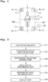
- the biological state monitoring system 100 of the first embodiment primarily has a load detecting unit 1, a control unit (controller) 3, and a storage unit 4.
- the load detecting unit 1 and the control unit 3 are connected via an A/D converting unit 2.
- the control unit 3 is further connected to a display unit 5, a notifying unit 6, and an input unit 7.
- the load detecting unit 1 includes four load detectors 11, 12, 13, and 14. Each of the load detectors 11, 12, 13, and 14 is a load detector for detecting a load by using, for example, a beam-type load cell. Such a load detector is disclosed, for example, in Japanese Patent No. 4829020 and Japanese Patent No. 4002905 . Each of the load detectors 11, 12, 13, and 14 is connected to the A/D converting unit 2 by way of wiring or wirelessly.
- the four load detectors 11 to 14 of the load detecting unit 1 are arranged respectively under casters C 1 , C 2 , C 3 , and C 4 fitted on the lower ends of legs BL 1 , BL 2 , BL 3 , and BL 4 at the four corners of the bed BD used by the subject S.
- the A/D converting unit 2 includes an A/D convertor connected respectively to the load detecting unit 1 and the control unit 3 by way of wiring or wirelessly, to convert analog signals fed from the load detecting unit 1 to digital signals.
- the control unit 3 is a dedicated or general-purpose computer inside which a standard deviation calculating unit 31, a respiratory waveform drawing unit 32 (respiratory waveform calculating unit; respiratory waveform obtaining(acquiring) unit), a body motion determining unit 33, and a respiratory rate estimating unit 34 (respiratory rate determining unit; respiratory rate calculating unit) are constructed.
- the storage unit 4 is a storage device for storing data used in the biological state monitoring system 100 and, for example, a hard disk (magnetic disk) can be used for that purpose.
- the display unit 5 is monitor such as a liquid crystal monitor or the like for displaying information outputted from the control unit 3 to users of the biological state monitoring system 100.
- the notifying unit 6 includes a device to auditorily perform a predetermined notification on the basis of the information fed from the control unit 3, such as a speaker, for example.
- the input unit 7 is an interface for performing predetermined inputs for the control unit 3, which may be a keyboard and a mouse.
- estimation of the respiratory rate of the subject performed by using the biological state monitoring system 100 includes a load detecting step S11 for detecting the load of a subject S, a standard deviation calculating step S12 for calculating a standard deviation showing the degree of variation of the detected load, a respiratory waveform drawing step S13 for drawing a respiratory waveform of the subject on the basis of the detected load, a body motion determining step S14 for determining the body motion of the subject by using the standard deviation found in the standard deviation calculating step S12, and the amplitude of the respiratory waveform drawn in the respiratory waveform drawing step S13, a respiratory rate estimating step S15 for estimating and outputting the respiratory rate of the subject on the basis of the respiratory waveform drawn in the respiratory waveform drawing step S13, and a display step S16 for displaying the outputted respiratory rate.
- the load detectors 11, 12, 13, and 14 are used to detect the load of the subject S on the bed BD.
- the load of the subject S on the bed BD is applied dispersively to the load detectors 11 to 14 arranged respectively under the legs BL 1 to BL 4 of the bed BD at the four corners.
- the load of the subject S is detected dispersively by the four load detectors.
- Each of the load detectors 11 to 14 detects the load (or variation of load), and outputs the result as an analog signal to the A/D converting unit 2.
- the A/D converting unit 2 converts the analog signal into a digital signal through a sampling period of 5 milliseconds, for example, and then outputs the digital signal (to be referred to below as "load signal") to the control unit 3.
- load signals s 1 , s 2 , s 3 , and s 4 will be used to refer respectively to the load signals obtained in the A/D converting unit 2 by converting the analog signals outputted from the load detectors 11, 12, 13, and 14 into the digital format.
- the standard deviation calculating unit 31 calculates standard deviations ⁇ 1 , ⁇ 2 , ⁇ 3 , and ⁇ 4 (moving standard deviations) of a sampling value included in a predetermined sampling period (5 seconds for example) for each of load signals s 1 , s 2 , s 3 , and s 4 .
- the calculation may be performed at any time (or continuously), with the sampling period of, for example, past 5 seconds.
- the standard deviation denotes the magnitude of variation(dispersion) of the sampling value.
- the standard deviations ⁇ 1 to ⁇ 4 become small during a period PER1 in which the subject S is resting on the bed BD and there is a small magnitude of variation in the load signals s 1 to s 4 .
- the standard deviations ⁇ 1 to ⁇ 4 become large during a period PER2 in which the subject S is moving his/her body (in which there is a body motion arising in the subject S) and there is a large magnitude of variation in the load signals s 1 to s 4 .
- the standard deviations ⁇ 1 to ⁇ 4 have larger values in comparison to a period when there is no body motion arising in the subject S.
- body motion refers to any motion of the subject's head, torso (trunk, body-trunk), and/or four limbs.
- the body motion does not include motions of internal organs, blood vessels and the like along with the respirations, heartbeats, and the like.
- the body motion can be classified into a large body motion along with the motion of the subject S in the torso (trunk, body-trunk), and a small body motion along with the motion of the subject only in the four limbs, the head, and/or the like.
- One example of the large body motion is turn-over, sit-up or get-up, or the like
- one example of the small body motion is, a motion of the hands, the feet, the head or the like during sleep.
- the load signals s 1 to s 4 fed from the load detectors 11 to 14 vary accordingly.
- the magnitude of variation increases in the order of the variation due to the heartbeats of the subject S, the variation due to the respirations of the subject S, the variation due to the small body motion of the subject S, and the variation due to the large body motion of the subject S.
- the term “the subject only (merely) respires (or the subject merely performs a respiration)", the load values and the load signals "vary due only to the respiration(s)", and the like are used to mean that the subject has no body motion, and the load values and the load signals show no variation due to the body motion, but not to mean that the subject does not have heartbeats, the load values and the load signals do not include the variation due to the heartbeats, etc.
- the respiratory waveform drawing unit 32 (respiratory waveform calculating unit; respiratory waveform obtaining(acquiring) unit) draws a respiratory waveform of the subject S on the basis of the load signals s 1 to s 4 .
- the respiration of human is performed by moving the chest and the diaphragm to expand and shrink the lungs.
- the air is inhaled (or an inspiration is performed), i.e., when the lungs are expanded, the diaphragm is lowered downwardly, and the internal organs are also moved downwardly.
- the air is expired (or an expiration is performed), i.e., when the lungs are shrunk, the diaphragm is raised upwardly, and the internal organs are also moved upwardly.
- the center of gravity G (of the subject) moves slightly along with the movement of the internal organs, the moving direction thereof being approximately along the subject's backbone extending direction (body axis direction).
- the term "respiratory waveform (respiration waveform)” refers to a waveform showing an aspect of the oscillation (vibration) of the subject's center of gravity oscillating (vibrating) in the subject's body axis direction due to the subject's respirations, by plotting the aspect on the temporal axis.
- One period of the respiratory waveform corresponds to one respiration of the subject (one inspiration and expiration).
- the amplitude of the respiratory waveform is affected by the subject's (physical) frame (build, physique) and/or respiratory depth.
- the amplitude becomes large
- the subject has a small frame or the subject performs a shallow respiration
- the respiratory waveform drawing unit 32 draws, in particular, the respiratory waveform in the following manner.
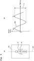
- the respiratory waveform drawing unit 32 calculates the position of the center of gravity G of the subject S at each sampling time on the basis of the load signals s 1 to s 4 fed from the load detecting unit 1. As depicted in Fig. 5(a) , the center of gravity G of the subject S oscillates in the direction of the body axis SA of the subject S in accordance with or due to the respiration of the subject S.
- the respiratory waveform drawing unit 32 draws a respiratory waveform BW ( Fig. 5(b) ) by way of plotting, on the vertical axis of a graph, the distance between the positions obtained by projecting the position of the center of gravity G at each time on the body axis SA, and the oscillation center of oscillation of the center of gravity G according to the respiration.
- the direction of the vertical axis of the graph matches the direction of the body axis SA.
- the horizontal axis of the graph shows time.
- the body motion determining unit 33 uses the standard deviations ⁇ 1 to ⁇ 4 calculated in the standard deviation calculating step S12 and the amplitude of the respiratory waveform BW drawn in the respiratory waveform drawing step S13, to determine whether or not there is a body motion arising in the subject S (whether or not the subject S has a body motion).
- the determination is performed in the following manner in particular for example.
- the body motion determining unit 33 detects the peaks for the respiratory waveform BW drawn in the respiratory waveform drawing step S13, and calculates the difference between the minimum value over the period between the latest peak p n and the previous peak p n-1 , and the latest peak p n , as the latest amplitude A n of the respiratory waveform BW ( Fig. 5(b) ). Then, the body motion determining unit 33 finds an average amplitude A AVn which is a simple average (value) of the amplitude A n and the amplitudes A n-1 , A n-2 , ... which are calculated before the amplitude A n . While an arbitrary number of amplitudes A n can be used for calculating the average amplitude A AVn , as one example, the number may be such as obtained in a sampling period of 5 seconds or so.
- the respiratory waveform BW which is involved in calculating the amplitudes A n , A n-1 , A n-2 , ... and the average amplitude A AVn , is the respiratory waveform obtained from a resting period (during which the subject only respires (performs respirations) without body motion arising), (i.e., in order to confirm that there is no error included due to the movement of the center of gravity because of some body motion), a comparison may be made between a threshold value ⁇ 0 and either a simple average ⁇ AV of the standard deviations ⁇ 1 to ⁇ 4 or any one of the standard deviations ⁇ 1 to ⁇ 4 .
- the threshold value ⁇ 0 is set at such a small value as able to reliably determine that there is no body motion arising in the subject S as long as the simple average ⁇ AV or any one of the standard deviations ⁇ 1 to ⁇ 4 is smaller than that value (conversely, even if the simple average ⁇ AV or any one of the standard deviations ⁇ 1 to ⁇ 4 is not smaller than that value, it is still possible that there is no body motion arising in the subject S).
- the body motion determining unit 33 finds normalized standard deviations ⁇ s 1 to ⁇ s 4 by the following Formula (Equation) 1.
- the body motion determining unit 33 finds a simple average ⁇ s AV of the calculated normalized standard deviations ⁇ s 1 to ⁇ s 4 and, based on a comparison between the simple average ⁇ s AV and a predetermined threshold value ⁇ s TH , determines whether or not there is a body motion arising in the subject S (whether or not the subject S has a body motion).
- the simple average ⁇ s AV is larger than or equal to the threshold value ⁇ s TH , then it is determined that there is a body motion arising in the subject S (the subject S has a body motion), whereas if the simple average ⁇ s AV is smaller than the threshold value ⁇ s TH , then it is determined that there is no body motion arising in the subject S (the subject S has no body motion).
- the body motion determining unit 33 calculates the latest amplitude A n for each one period of the respiratory waveform BW on the basis of the respiratory waveform BW acquired by the respiratory waveform drawing unit 32. Then, using the average amplitude A AVn calculated anew by using the value of the calculated latest amplitude A n , and the values of the standard deviations ⁇ 1 to ⁇ 4 calculated at each sampling time (as an example, every 5 milliseconds), the body motion determining unit 33 calculates, successively, the normalized standard deviations ⁇ s 1 to ⁇ s 4 by the Formula 1 and calculates the simple average ⁇ s AV .
- Determining whether or not there is a body motion arising in the subject S is performed by the successive comparisons between the predetermined threshold value ⁇ s TH and the simple average ⁇ s AV calculated successively in the above manner.
- the body motion determining unit 33 After it is determined as a result of the determination that there is a body motion arising in the subject S, the body motion determining unit 33 ceases to update the average amplitude A AVn and continues to calculate the simple average ⁇ s AV using the average amplitude AAvn having been calculated by this point. Then, based on a comparison between the calculated simple average ⁇ s AV and the threshold value ⁇ s TH , the body motion determining unit 33 continues to determine whether or not there is a body motion arising in the subject S.
- the body motion determining unit 33 calculates the value of the latest amplitude A n and, using the same, calculates the average amplitude A AVn anew. Then, the body motion determining unit 33 calculates the simple average ⁇ s AV using the latest average amplitude A AVn and, based on a comparison between the calculated simple average ⁇ s AV and the predetermined threshold value ⁇ s TH , the body motion determining unit 33 continues to determine whether or not there is a body motion arising in the subject S.
- the body motion determining unit 33 uses the average amplitude A AV1 which is the simple average of the amplitude A 1 and the amplitudes A 0 , A- 1 , ...
- the body motion determining unit 33 uses the average amplitude A AV2 calculated by using the amplitude A 2 , to calculate successively the normalized standard deviations ⁇ s 1 to ⁇ s 4 and the simple average ⁇ s AV (to be referred to here as ⁇ s AV (A AV2 )); and determines whether or not there is a body motion arising in the subject S, based on the comparison between the simple average ⁇ s AV (A AV2 ) and the threshold value ⁇ s TH .
- the body motion determining unit 33 determines that there is a body motion arising in the subject S on the basis of the simple average ⁇ s AV (A AV2 ) being equal to or larger than the threshold value ⁇ s TH . Then, after that, for the period when the simple average ⁇ s AV (A AV2 ) is equal to or larger than the threshold value ⁇ s TH , the body motion determining unit 33 continues to determine the body motion using the simple average ⁇ s AV (A AV2 ).
- the body motion determining unit 33 determines that there is no body motion arising in the subject S on the basis of the simple average ⁇ s AV (A AV2 ) being smaller than the threshold value ⁇ s TH . After that, the body motion determining unit 33 continues to determine the body motion using the simple average ⁇ s AV (A AV2 ) until the latest amplitude A n of the respiratory waveform BW is obtained and the latest average amplitude A AVn is calculated again.
- the body motion determining unit 33 uses the amplitude A n (average amplitude A AVn ) of the respiratory waveform to normalize the values of the standard deviations ⁇ 1 to ⁇ 4 .
- the reason therefor is as follows.
- the values of the standard deviations ⁇ 1 to ⁇ 4 become larger during a period when there is a body motion arising in the subject S. Therefore, it is conceivable to determine whether or not there is a body motion arising in the subject S by way of comparison between the values of the standard deviations ⁇ 1 to ⁇ 4 and a predetermined threshold value.
- the values of the standard deviations ⁇ 1 to ⁇ 4 may still be comparatively large even during a period of only performing respirations without the body motion because the movement of his/her internal organs due to the respirations is also large. Further, even for a subject who does not have a large frame, the values may still become large if, for example, the subject performs a deep respiration.
- the body motion determination is performed by comparing the values of the standard deviations ⁇ 1 to ⁇ 4 to a predetermined threshold value, in such a case, even though there is no body motion arising in the subject, a mistaken determination may be made to give the incorrect result that there is a body motion arising in the subject.
- the amplitude of the respiratory waveform is affected by the subject's frame and/or respiratory depth; therefore, if the subject has a large frame or the subject performs a deep respiration, then the amplitude becomes large, whereas if the subject has a small frame or the subject performs a shallow respiration, then the amplitude becomes small.
- the respiratory rate estimating unit 34 estimates (determines) the respiratory rate of the subject S on the basis of the respiratory waveform BW of the subject S drawn in the respiratory waveform drawing step S13, and outputs the estimated (determined) respiratory rate to the display unit 5.
- the respiratory rate estimating unit 34 estimates the respiratory rate on the basis of the respiratory waveform BW by the following method.
- the respiratory rate estimating unit 34 detects peaks in predetermined periods for the respiratory waveform BW drawn in the respiratory waveform drawing step S13. Then, when a new peak is detected, the respiratory rate estimating unit 34 finds distances (to be referred to below as inter-peak distances t) between any two adjacent peaks of the plurality of peaks included between a first time point at which the new peak is detected and a second time point before (preceding) the first time point by a predetermined time period (25 seconds for example; to be referred to below as "sampling time period for estimation" as appropriate).
- Fig. 7 depicts one example of the respiratory waveform BW included in the sampling time period for estimation over 25 seconds with peaks p 1 to p 6 of the respiratory waveform BW, and inter-peak distances t 1 to t 5 between the peaks p 1 to p 6 .
- the respiratory rate estimating unit 34 finds an average value t AV of the plurality of inter-peak distances t by the following Formula 2.
- N is the number of peaks of the respiratory waveform BW included in the sampling time period for estimation.
- the average value t AV approximately corresponds to the average value of the respiratory periods of the subject S during the sampling time period for estimation.
- the respiratory rate estimating unit 34 calculates an estimated value R of the respiratory rate over one minute of the subject S by the following Formula 3. Then, the calculated estimated value R is outputted to the display unit 5 as the estimated respiratory rate.
- R 60 / t AV
- the respiratory rate estimating unit 34 of this embodiment adjusts the value of the respiratory rate for output according to whether or not the subject S has a body motion. This adjustment will be explained as follows.
- the respiratory rate estimating unit 34 successively calculates the estimated value R of the respiratory rate by using the Formulas 2 and 3 according to the above method whenever a peak of the respiratory waveform BW is detected both in a period (resting period) when the body motion determining unit 33 determines that the subject S does not have a body motion and in a period (body motion period) when the body motion determining unit 33 determines that the subject S has a body motion.
- the calculated estimated values R are outputted successively to the display unit 5 as the estimated respiratory rates.
- the respiratory rate estimating unit 34 outputs the estimated value (first estimated value) R calculated right before the transition (shifting) from the resting period to the body motion period, that is, the estimated value R calculated last in the resting period right therebefore, instead of the estimated value R of the respiratory rate calculated successively by using the Formulas 2 and 3 according to the above method, to the display unit 5 as the estimated respiratory rate.
- the respiratory rate estimating unit 34 outputs the value outputted in the preceding body motion period, that is, the estimated value R calculated right before the transition from the first resting period to the body motion period, to the display unit 5 as the estimated respiratory rate, instead of the estimated value R of the respiratory rate calculated successively by using the Formulas 2 and 3 according to the above method.
- the respiratory rate estimating unit 34 finds (obtains) the inter-peak distance t between those two peaks, and uses the value of the inter-peak distance t as the value of the average value t AV to calculate the estimated value R of the respiratory rate by the Formula 3. Then, the respiratory rate estimating unit 34 outputs the estimated value R calculated anew to the display unit 5 as the estimated respiratory rate, instead of the value outputted fixedly in the body motion period and the following predetermined period, that is, the estimated value R calculated right before the transition from the first resting period to the body motion period.
- the respiratory rate estimating unit 34 obtains the inter-peak distances t between two adjacent peaks of the three and four peaks, respectively, to calculate the estimated value R of the respiratory rate by the Formula 3 by using a simple average (value) of those obtained inter-peak distances t as the value of the average value t AV . Then, the respiratory rate estimating unit 34 outputs the calculated values as the estimated respiratory rate to the display unit 5.
- the respiratory rate estimating unit 34 restarts calculating the average value t AV by using the above Formula 2 to calculate the estimated value R by applying the calculated average value t AV to the above Formula 3, and output the calculated value to the display unit 5 as the estimated respiratory rate.
- the respiratory rate estimating unit 34 calculates the estimated value R of the respiratory rate by the above Formulas 2 and 3, on the basis of the respiratory waveform BW found in the sampling time period for estimation over 25 seconds with the time T 4 as the terminal, and outputs the calculated value as the estimated respiratory rate.
- the respiratory rate R 4 is outputted.
- the respiratory rate estimating unit 34 calculates the estimated values R of the respiratory rate by the above Formulas 2 and 3, on the basis of the respiratory waveform BW found in the sampling time period for estimation with the times T 5 and T 6 as the terminals, and outputs the calculated values as the estimated respiratory rates.
- the respiratory rates R 5 and R 6 are outputted.
- the respiratory rate estimating unit 34 switches the estimated value of the respiratory rate for output from the estimated value R calculated anew by using the above Formulas 2 and 3 to the estimated value calculated right before the time T 61 (equal to the respiratory rate R 6 ), on the basis of the body motion determining unit 33 having determined that the subject S has a body motion. Then, during the period when the body motion determining unit 33 determines that the body motion is arising in the subject S (the subject S has the body motion), that is, during the body motion period, the respiratory rate estimating unit 34 keeps outputting the respiratory rate R 6 as the estimated respiratory rate.
- the respiratory rate estimating unit 34 also keeps outputting the estimated value calculated right before the time T 61 (equal to the respiratory rate R 6 ) as the estimated respiratory rate, through a predetermined period, instead of the estimated value R calculated anew by using the above Formulas 2 and 3.
- the respiratory rate estimating unit 34 finds the inter-peak distance t 8 between the first peak P 7 and the peak P 8 after the body motion of the subject S comes to the end. Then, using the inter-peak distance t 8 as the average value t AV , the respiratory rate estimating unit 34 calculates the estimated value R of the respiratory rate by the Formula 3, and outputs the newly calculated estimated value R as the estimated respiratory rate instead of the value outputted fixedly after the time T 61 (the respiratory rate R 6 ). Here, suppose that the respiratory rate R 8 is outputted.
- the respiratory rate estimating unit 34 After detecting the third peak P 9 after the body motion of the subject S comes to an end at the time Tg, the respiratory rate estimating unit 34 finds the inter-peak distance tg between the second peak P 8 and the peak P 9 after the body motion of the subject S comes to the end. Then, using a simple average of the inter-peak distance t 8 and the inter-peak distance t 9 as the average value t AV , the respiratory rate estimating unit 34 calculates the estimated value R of the respiratory rate by the Formula 3, and outputs the calculated value as the estimated respiratory rate. Here, suppose that the respiratory rate R 9 is outputted.
- the respiratory rate estimating unit 34 finds the inter-peak distance t 10 between the peak Pg and the peak P 10 , and the inter-peak distance t 11 between the peak P 10 and the peak P 11 . Then, using the simple average of what has already been obtained in the inter-peak distances t 8 to t 11 as the average value t AV , it calculates the estimated value R of the respiratory rate by the Formula 3, and outputs the calculated value as the estimated respiratory rate.
- the respiratory rates R 10 and R 11 are outputted.
- the respiratory rate estimating unit 34 restarts calculating the average value t AV by using the above Formula 2, to calculate the estimated value R of the respiratory rate by applying the calculated average value t AV to the above Formula 3. Then, it outputs the calculated value to the display unit 5 as the estimated respiratory rate.
- the following statement is the reason why the respiratory rate estimating unit 34 outputs the estimated value R of the respiratory rate, calculated right before the transition from the resting period to the body motion period, as the estimated value of the respiratory rate of the subject S instead of the estimated value R calculated, in the body motion period and the predetermined initial period of the following resting period.
- the respiratory waveform BW is affected and disturbed by the body motion of the subject S whereby the period of the respiratory waveform BW is also varying. Therefore, the inter-peak distances found on the basis of the peaks of the respiratory waveform BW in the body motion period do not reflect the respiratory period by their values. If the sampling time period for estimation includes a body motion period, then the average value t AV found by the Formula 2 is affected by the inter-peak distances which do not reflect the respiratory period in this manner. Therefore, there is also a high possibility for the estimated value R of the respiratory rate calculated by using the Formula 3 to deviate from the actual respiratory rate of the subject.
- the respiratory rate estimating unit 34 outputs the estimated value R calculated right before the transition from the resting period to the body motion period as the estimated value for those periods, instead of the estimated value R calculated anew.
- the respiratory rate estimating unit 34 outputs the estimated value R calculated right before the transition from the resting period to the body motion period as the estimated value for those periods, instead of the estimated value R calculated anew.
- the respiratory rate estimating unit 34 may cease to detect the peaks of the respiratory waveform BW, cease to calculate the inter-peak distances, and cease to calculate the estimated values R using the Formulas 2 and 3, during the body motion period and during the predetermined period after the transition from the body motion period to the resting period.
- the estimated value R is calculated by using the inter-peak distance between those peaks, and the calculated value is outputted.
- this method after the transition from the body motion period to the resting period, it is possible to restart calculating and outputting the estimated value R of the respiratory rate with exclusion of the influence of disturbance of the respiratory waveform BW in the body motion period, without waiting for the passage of the time equivalent to the sampling time period for estimation.
- the control unit 3 causes the display unit 5 to display the respiratory rate (estimated value) of the subject S outputted in the respiratory rate estimating step S15.
- the notifying unit 6 may be used to perform a notification in addition to or instead of the display using the display unit 5. In this case, for example, when the respiratory rate of the subject S reaches a predetermined set value, a notification sound may be emitted to notify the nurses, caregivers and/or others who are the users of the biological state monitoring system 100.
- the respiratory rate estimating unit 34 included in the biological state monitoring system 100 of this embodiment outputs the estimated value calculated right before an occurrence of the body motion, during a period in which the body motion is kept and during a predetermined period succeeding an end of the body motion, as the estimated value of the respiratory rate for those periods.
- the biological state monitoring system 100 of this embodiment can suppress the influence of the body motion, thereby outputting the estimated value of the respiratory rate of the subject S with high reliability.
- the respiratory rate estimating unit 34 included in the biological state monitoring system 100 of this embodiment restarts, at the point of detecting two peaks of the respiratory waveform BW after the transition from the body motion period to the resting period, calculating the estimated value of the respiratory rate by using the inter-peak distance between those peaks. Therefore, it is possible for the biological state monitoring system 100 of this embodiment to release the respiratory rate displayed on the display unit 5 from the state fixed at the value estimated right before a body motion, at an earlier timing after the end of the body motion.
- the biological state monitoring system 100 of this embodiment uses the load detectors 11 to 14 arranged under the legs BL 1 to BL 4 of the bed BD to determine whether or not the subject S has a body motion. Therefore, it is not necessary to attach any measuring device to the body of the subject S so that the subject S will not feel discomfort and a sense of incongruity.
- the respiratory rate estimating unit 34 fixes the estimated value of the respiratory rate of the subject S for output at the estimated value (the first estimated value) calculated right before a body motion period, during the body motion period and the like when a disturbance arises in the respiratory waveform due to the body motion of the subject S. In such a manner, the biological state monitoring system 100 prevents degradation of the reliability of the estimated value of the respiratory rate due to the influence of disturbance of the respiratory waveform.
- a motion of muscle spasm which is called a twitch (a jerk) may occur in a person during REM sleep.
- a twitch is also a kind of body motion.
- the present inventors have made researches on the influence of a twitch on biological state monitoring and obtained the discovery and knowledge that even if the subject S performs a twitch, the twitch will not give rise to a large disturbance in the respiratory waveform. It is conceived that this is because the influence of the twitch which is a body motion over a short duration time (continuance time) is eliminated or reduced in the calculating process or filtering process for obtaining the respiratory waveform.
- the body motion determining unit still determines that a body motion has arisen.
- the biological state monitoring system 200 of the second embodiment is based on the above discovery and knowledge of the present inventors, and configured not to perform estimation fixing (estimated value fixing), performed by the respiratory rate estimating unit 34 of the biological state monitoring system 100 of the first embodiment, even when the body motion determining unit determines that the subject has the body motion, provided that the body motion is a twitch.
- estimation fixing estimated value fixing
- the biological state monitoring system of the second embodiment can output the estimated value of the respiratory rate of the subject with even higher reliability.
- the biological state monitoring system 200 of the second embodiment ( Fig. 9 ) has the same configuration as the biological state monitoring system 100 of the first embodiment except for the aspect of including a twitch determining unit 35 configured to determine whether or not the body motion of the subject is a twitch. Explanation will be omitted for any configuration common to the biological state monitoring systems 100 and 200 of the first and second embodiments. How the twitch determining unit 35 operates will be described latter on.
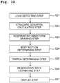
- estimation of the respiratory rate of the subject performed by using the biological state monitoring system 200 includes a load detecting step S21 for detecting the load of the subject S, a standard deviation calculating step S22 for calculating the standard deviation showing the degree of variation of the detected load, a respiratory waveform drawing step S23 for drawing the respiratory waveform of the subject on the basis of the detected load, a body motion determining step S24 for determining the body motion of the subject by using the standard deviation found in the standard deviation calculating step S22, and the amplitude of the respiratory waveform drawn in the respiratory waveform drawing step S23, a twitch determining step S25 for determining whether or not the body motion of the subject S is a twitch, a respiratory rate estimating step S26 for estimating and outputting the respiratory rate of the subject on the basis of the respiratory waveform drawn in the respiratory waveform drawing step S23, and a display step S27 for displaying the outputted respiratory rate.
- the load detecting step S21, the standard deviation calculating step S22, the respiratory waveform drawing step S23, the body motion determining step S24, and the display step S27 are substantially (practically) the same, respectively, as the load detecting step S11, the standard deviation calculating step S12, the respiratory waveform drawing step S13, the body motion determining step S14, and the display step S16 which are carried out by the biological state monitoring system 100 of the first embodiment. Therefore, explanations therefor will be omitted.
- the twitch determining unit 35 determines whether or not the body motion arising in the subject S is a twitch on the basis of the determination result of the body motion determining unit 33. In particular, the determination is performed by the following method.
- the twitch determining unit 35 receives the determination result of body motion from the body motion determining unit 33 and, at the point of change from absence of body motion to presence of body motion in the determination result, starts measuring the length of time. Then, the twitch determining unit 35 obtains, by a measurement, a length of time (duration, duration time) from the time point at which the determination result of the body motion determining unit 33 changes from absence of body motion to presence of body motion until the time point at which the determination result return to absence of body motion, and compares the found duration time to a predetermined threshold value D th .
- a length of time duration, duration time
- this body motion is determined as a twitch of which duration is short.
- this body motion is determined as not a twitch but a body motion of which duration is long.
- the threshold value D th used for the determination may be set as appropriate on the basis of the duration of an ordinary twitch. Further, the threshold value D th may be set by considering such a time, as extending until a vibration, which arose in the bed and the like from the influence of a twitch, comes to an end. Alternatively, the threshold value D th may be set by considering other factors with an actual installation of the system. The threshold value D th may be about 0.5 seconds to 6 seconds, in particular for example.
- a body motion whose duration is shorter than a predetermined time period or, in other words, a body motion of which occurrence affects the body motion determination for a time period shorter than a predetermined time period (0.5 to 6 seconds for example) is regarded as a twitch.
- the respiratory rate estimating unit 34 calculates and outputs the estimated value of the respiratory rate of the subject S, on the basis of the respiratory waveform BW drawn by the respiratory waveform drawing unit 32, the determination result given by the body motion determining unit 33, and the determination result given by the twitch determining unit 35.
- the respiratory rate estimating unit 34 receives the respiratory waveform BW from the respiratory waveform drawing unit 32 and the determination result from the body motion determining unit 33, and use these two items with a delay of a predetermined time X. The reason for such a delay will be described later on.
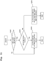
- the respiratory rate estimating unit 34 first determines whether or not there is a body motion arising in the subject S on the basis of the determination result by the body motion determining unit 33 (S261, Fig. 11 ). Then, if there is no body motion arising in the subject S (S261: No), then the respiratory rate estimating unit 34 outputs the estimated values R calculated successively anew by the Formulas 2 and 3, to the display unit 5 in sequence as the estimated respiratory rate (S263, Fig. 11 ).
- the respiratory rate estimating unit 34 carries out the following process, which is different from the respiratory rate estimating step S15 of the first embodiment.
- the respiratory rate estimating unit 34 first determines whether or not the body motion is a twitch on the basis of the determination result by the twitch determining unit 35 (S262, Fig. 11 ).
- the respiratory rate estimating unit 34 outputs the estimated value (the first estimated value) R, calculated right before the transition from the resting period to the body motion period, to the display unit 5 as the estimated respiratory rate, instead of the estimated value R of the respiratory rate calculated successively by using the Formulas 2 and 3 (S264, Fig. 11 ), like the process in the respiratory rate estimating step S15 of the first embodiment performed when there is a body motion arising in the subject S.
- the process after the subsequent shift from the body motion period to the resting period is also the same as the process performed in the respiratory rate estimating step S15 of the first embodiment.
- the respiratory rate estimating unit 34 successively outputs the estimated values R calculated anew by using the Formulas 2 and 3, to the display unit 5 as the estimated respiratory rates (S263, Fig. 11 ). That is, the respiratory rate estimating unit 34 is configured such that, even if the body motion determining unit 33 determines that there is a body motion arising in the subject S, provided that the twitch determining unit 35 determines that the body motion is a twitch, the respiratory rate estimating unit 34 carries out the same process as for the resting period without regarding the period of the arising body motion as a body motion period.
- the respiratory rate estimating unit 34 uses the respiratory waveform BW received from the respiratory waveform drawing unit 32 and the body motion determination result received from the body motion determining unit 33, with a delay of the predetermined time X. Therefore, if the predetermined time X is larger than the threshold value D th , then at the point when the determination result by the body motion determining unit 33 changes from absence of body motion to presence of body motion in the process carried out by the respiratory rate estimating unit 34, the twitch determining unit 35 is already finished with the determination of whether or not the body motion is a twitch. Therefore, as described above, the respiratory rate estimating unit 34 can determine (confirm) whether or not the body motion is a twitch at the point when the determination result by the body motion determining unit 33 changes from absence of body motion to presence of body motion.
- Figs. 12(a) and 12(b) will be used to explain a particular example of this process. Note that in the lower graph of Fig. 12(a) , and in Fig. 12(b) , " 1 " means presence of body motion and "0" means absence of body motion, on the vertical axis.
- the twitch determining unit 35 measures the duration (continuance time) from that point to a time T 14 when the determination result by the body motion determining unit 33 returns to absence of body motion again, and compares the found duration to the threshold value D th .
- the threshold value D th is 3 seconds
- the duration from the time T 13 to the time T 14 is 2 seconds. Therefore, the twitch determining unit 35 determines that the body motion arising over the period from the time T 13 to the time T 14 is a twitch.
- the respiratory rate estimating unit 34 determines the contents of the following process with reference to the determination result by the twitch determining unit 35, on the basis of the determination result by the body motion determining unit 33 stating that there is a body motion arising in the subject S.
- the respiratory rate estimating unit 34 successively outputs the estimated value R calculated anew by using the Formulas 2 and 3 to the display unit 5, as the estimated respiratory rate.
- the estimated value indicates the state of the subject S around the time T 13 , and is outputted after the time T 13 + X, that is, being delayed by the predetermined time X.
- the body motion determining unit 33 determines that there is a body motion arising in the subject S at a time T 15 . If the body motion determining unit 33 determines that there is a body motion arising in the subject S at a time T 15 , then the twitch determining unit 35 restarts to measure the time from that point. Then, the twitch determining unit 35 determines that the body motion is not a twitch at the point when the period, for which the body motion determining unit 33 has determined as "presence of body motion" exceeds the threshold value D th (3 seconds in this case). In this context, it is assumed that the body motion determining unit 33 has determined that the body motion arising continuously from the time T 15 is not a twitch, prior to the time T 15 + X.
- the respiratory rate estimating unit 34 determines the contents of the following process with reference to the determination result by the twitch determining unit 35 again, on the basis of the determination result by the body motion determining unit 33 stating that there is a body motion arising in the subject S.
- the respiratory rate estimating unit 34 outputs the estimated value R calculated right before the time T 15 + X, to the display unit 5 as the estimated respiratory rate. While the estimated value indicates the state of the subject S after the time T 15 , it is outputted after the time T 15 + X with a delay of the predetermined time X.
- the biological state monitoring system 200 of the second embodiment has the following effects in addition to the effects of the biological state monitoring system 100 of the first embodiment.
- the biological state monitoring system 200 of the second embodiment includes the twitch determining unit 35 such that even if there is a body motion arising in the subject S, provided that the body motion is a twitch which exerts a small influence on calculating the estimated value of the respiratory rate, the respiratory rate estimating unit 34 is caused to keep on outputting the estimated value R calculated anew.
- the biologial state monitoring system 200 of the second embodiment can shorten the period in which the estimated value calculated in the past resting period is outputted alternatively to a minimum (bare minimum), by determining whether or not the body motion is a twitch. Therefore, it is possible to output the estimated value of the respiratory rate of the subject with higher reliability.
- the respiratory rate estimating unit 34 of the biological state monitoring system 200 of the above second embodiment carries out the process for the respiratory waveform BW received from the respiratory waveform drawing unit 32 and the body motion determination result received from the body motion determining unit 33, with a delay of the predetermined time X.
- the respiratory waveform BW may be drawn a predetermined length of time later than the body motion is determined by the body motion determining unit 33.
- the twitch determining unit 35 even without the respiratory rate estimating unit 34 purposely applying a delay, it is still possible for the twitch determining unit 35 to finish the determination before the process is carried out by the respiratory rate estimating unit 34.
- the respiratory rate estimating unit 34 of the biological state monitoring systems 100 and 200 of the above embodiments may be configured to maintain the estimated value of the respiratory rate for output at the estimated value R calculated right before the body motion period only within the body motion period, after it is determined that there is a body motion arising in the subject S.
- the body motion period may continue as long as the body motion is arising in the subject S, and thus may extend over a longtime period.
- the predetermined period after a body motion comes to an end is the sampling period for estimation or so at the longest and, in the above first and second embodiments, is about 25 seconds.
- the biological state monitoring systems 100 and 200 of the above embodiments may cease to output the estimated value of the respiratory rate of the subject S in the body motion period and/or the predetermined initial period of the resting period right after the body motion period, after a body motion is determined as arising in the subject S.
- the users of the biological state monitoring systems 100 and 200 can predict the estimated value of the current respiratory rate of the subject by memorizing the estimated value of the respiratory rate outputted last (that is, the estimated value R calculated right before the body motion period), for example.
- the respiratory rate estimating unit 34 may estimate the respiratory rate of the subject S without using the respiratory waveform BW.
- the respiratory rate estimating unit 34 calculates the respiratory rate of the subject S by carrying out the Fourier analysis on at least one of the load signals s 1 to s 4 corresponding to the predetermined sampling period so as to specify the peak frequency coming up in the frequency band corresponding to the respirations (from about 0.2 Hz to about 0.33 Hz because the human respiration is performed about 12 to 20 times per minute). With the specified peak frequency, it is possible to calculate (estimate) the respiratory rate of the subject S over that period.
- the reliability of the calculated respiratory rate (estimated value) of the subject S may decrease due to a variation of the load signals s 1 to s 4 arising from the body motion. Therefore, it is possible to raise the reliability of the estimated value of the respiratory rate by adjusting the outputted value by the same method as used by the respiratory rate estimating unit 34 of the above embodiments.
- the body motion determining unit 33 normalizes the standard deviations ⁇ 1 to ⁇ 4 by dividing the standard deviations ⁇ 1 to ⁇ 4 by the average amplitude A AVn to reduce (compensate; correct) the influence on the values of the standard deviations ⁇ 1 to ⁇ 4 , exerted by the frame and/or respiratory depth of the subject S.
- the compensating (correcting) method by utilizing the amplitude of the respiratory waveform BW is not limited to that.
- the standard deviations ⁇ 1 to ⁇ 4 may be normalized by way of dividing the same by the latest amplitude A n of the respiratory waveform BW.
- the two methods mentioned above are practically equivalent and thus it is possible to appropriately select either the standard deviations or the threshold value used in the comparison for the compensation (correction) by the amplitude of the respiratory waveform.
- the expression "compensating the standard deviations by the amplitude of the respiratory waveform” is termed to include compensating the threshold value by the amplitude of the respiratory waveform.
- the body motion determining unit 33 performs the body motion determination by the comparison between the simple average ⁇ s AV of the normalized standard deviations ⁇ s 1 to ⁇ s 4 and the threshold value ⁇ s TH .
- the body motion determining unit 33 it is also capable for the body motion determining unit 33 to use a variance which is the squared standard deviation instead of the standard deviation. If the variance is normalized by the amplitude of the respiratory waveform, then the variance may be divided by the squared amplitude of the respiratory waveform. Therefore, in the present specification and in the present invention, the standard deviation is termed to include the variance.
- the body motion determining unit 33 may provide the threshold value used for the body motion determination with hysteresis. In particular, for example, with a first threshold value and a second threshold value larger than the first threshold value set in advance, under the condition that the subject S is determined as with no body motion arising therein, as far as the simple average ⁇ s AV is yet smaller than the second threshold value, the subject S is not determined as with a body motion arising therein.
- the subject S under the condition that the subject S is determined as with a body motion arising therein, even if the simple average ⁇ s AV is smaller than the second threshold value, the subject S is not determined as with no body motion arising therein, but is determined as with no body motion arising therein at the point of the simple average ⁇ s AV becoming smaller than the first threshold value.
- the body motion determining unit 33 may determine whether or not the subject S has a body motion on the basis of a comparison between at least one of the standard deviations ⁇ 1 to ⁇ 4 and the threshold value, or a comparison between the total value or a simple average of at least two or more of the standard deviations ⁇ 1 to ⁇ 4 and the threshold value, without finding the normalized standard deviations ⁇ s 1 to ⁇ s 4 .
- the body motion determining unit 33 can also determine whether or not the subject S has a body motion without using the standard deviations ⁇ 1 to ⁇ 4 . In particular, for example, it determines whether or not the subject S has a body motion on the basis of a movement of the center of gravity of the subject S.
- the center of gravity G of the subject S oscillates in the direction of the body axis SA of the subject S according to the respirations of the subject S ( Fig. 5(a) ). Further, the center of gravity G of the subject S moves according to that if the subject S has a small body motion or a large body motion. Then, the moving distance of the center of gravity G over a predetermined period increases in the ascending order of the period when the subject S only respires, the period when the subject S has a small body motion, and the subject S has a large body motion.
- the body motion determining unit 33 can determine whether or not the subject S has a body motion by comparing a predetermined threshold value with the moving distance of the center of gravity G over a predetermined period. In particular, for example, it is possible to determine that the subject S has a small body motion if the moving distance d of the center of gravity G over a predetermined period is longer than a threshold value dth.
- the biological state monitoring systems 100 and 200 of the above embodiments do not need to include all of the load detectors 11 to 14 but may include only any one of the four. For example, if there are three such load detectors, then it is still possible to detect the position of the center of gravity G of the subject S on the plane of the bed BD provided that the three load detectors are not arranged on a straight line. Further, the load detectors do not need to be arranged at the four corners of the bed but may be arranged in any positions as far as they can detect the load of the subject on the bed and the variation thereof. Further, the load detectors 11 to 14 are not limited to load sensors using beam-type load cells but, for example, force sensors are also usable.
- the load detectors 11 to 14 are arranged respectively on the undersides of the casters C attached to the lower ends of the legs of the bed BD.
- Each of the load detectors 11 to 14 may be provided respectively between one of the four legs of the bed BD and the board of the bed BD.
- each of the load detectors 11 to 14 may be provided between the upper leg and the lower leg.
- the load detectors 11 to 14 may be formed integral with or removable from the bed BD to construct a bed system BDS comprising the bed BD, and the biological state monitoring system 100 or 200 of the first or second embodiment ( Fig. 13 ) .
- the load detecting unit 1 between the load detecting unit 1 and the A/D converting unit 2, it is possible to provide a signal amplifying unit to amplify the load signals fed from the load detecting unit 1, and a filtering unit to eliminate the noises from the load signals.
- the display unit 5 may include a printer for printing out the information indicating the biological state (respiratory rate, presence or absence of body motion, etc.), a simplified visual display means such as lamps indicating the biological state (respiratory rate, presence or absence of body motion, etc.), and/or the like, instead of the monitor or in addition to the monitor.
- the notifying unit 6 may include a vibration generating unit for performing the notification by way of vibration, instead of the speaker or in addition to the speaker.
- the biological state monitoring system of the present invention it is possible to suppress the influence of body motion of the subject so as to estimate the respiratory rate of the subject with high precision. Therefore, by using the biological state monitoring system of the present invention, it is possible to provide high-quality medical treatments and caregiving services on the basis of the high-precision estimation of the respiratory rate.
Landscapes
- Health & Medical Sciences (AREA)
- Life Sciences & Earth Sciences (AREA)
- Engineering & Computer Science (AREA)
- Public Health (AREA)
- Molecular Biology (AREA)
- Veterinary Medicine (AREA)
- General Health & Medical Sciences (AREA)
- Physics & Mathematics (AREA)
- Animal Behavior & Ethology (AREA)
- Biophysics (AREA)
- Pathology (AREA)
- Biomedical Technology (AREA)
- Heart & Thoracic Surgery (AREA)
- Medical Informatics (AREA)
- Surgery (AREA)
- Physiology (AREA)
- Pulmonology (AREA)
- Dentistry (AREA)
- Oral & Maxillofacial Surgery (AREA)
- Signal Processing (AREA)
- Computer Vision & Pattern Recognition (AREA)
- Artificial Intelligence (AREA)
- Psychiatry (AREA)
- Measurement Of The Respiration, Hearing Ability, Form, And Blood Characteristics Of Living Organisms (AREA)
- Measuring And Recording Apparatus For Diagnosis (AREA)
Abstract
Description
- The present invention relates to a biological state monitoring system for monitoring a biological state of a (human) subject on a bed on the basis of detection value of a load detector.
- For the sites of medical treatment and caregiving service, it is proposed to monitor a biological state (biological condition) of a subject on the basis of such a (body weight) load of the subject on a bed as detected by load detectors. In particular, for example, it is proposed to estimate a respiratory rate of the subject on the basis of the detected load.
-
Patent Literature 1 discloses that the subject's respiratory rate is detected by a frequency analysis of a measuring value of load sensors arranged under legs of a bed.Patent Literature 2 discloses that load detectors are arranged under legs of a bed to find a movement of the center of gravity of a biological subject under detection on a bed and, based on the movement of the center of gravity, a respiratory motion and heartbeats of the biological subject under detection is found. -
- Patent Literature 1: Japanese Patent No.
4883380 - Patent Literature 2: Japanese Examined Patent Publication
61-24010 - An object of the present invention is to provide a biological state monitoring system capable of outputting an estimated value of the respiratory rate of a subject with high reliability.
- According to a first aspect of the present invention, there is provided a biological state monitoring system for monitoring a biological state of a subject on a bed, the system including:
- at least one load detector configured to detect a load of the subject on the bed;
- a body motion determining unit configured to determine whether or not the subject has a body motion, based on a temporal variation of a detection value of the load detector;
- a respiratory rate estimating unit configured to successively obtain and output estimated values of respiratory rate of the subject, based on the temporal variation of the detection value of the load detector; and
- a twitch determining unit configured to determine whether or not a body motion is a twitch, based on a duration of the body motion of the subject,
- wherein in a case that the twitch determining unit determines that the body motion is not a twitch, the respiratory rate estimating unit ceases to output the estimated value of the respiratory rate, or outputs a first estimated value which is the latest among the estimated values obtained in a first period, the first period being directly preceding the body motion and being determined by the body motion determining unit to be a period in which the subject has no body motion, and
- in a case that the twitch determining unit determines that the body motion is a twitch, the respiratory rate estimating unit successively outputs newly obtained estimated values of the respiratory rate.
- In the biological state monitoring system according to the first aspect, in a case that the twitch determining unit determines that the body motion is not a twitch, the respiratory rate estimating unit may output the first estimated value.
- In the biological state monitoring system according to the first aspect, the twitch determining unit may determine whether or not a body motion of the subject is a twitch, based on a comparison between a predetermined threshold value and a length of a period which is determined by the body motion determining unit to be a period in which the subject has a body motion.
- According to a second aspect of the present invention, there is provided a biological state monitoring system for monitoring a biological state of a subject on a bed, the system including:
- at least one load detector configured to detect a load of the subject on the bed;
- a body motion determining unit configured to determine whether or not the subject has a body motion, based on a temporal variation of a detection value of the load detector; and
- a respiratory rate estimating unit configured to successively obtain and output estimated values of respiratory rate of the subject, based on the temporal variation of the detection value of the load detector,
- wherein, during a period which is determined by the body motion determining unit to be a second period in which the subject has the body motion, the respiratory rate estimating unit ceases to output the estimated value of the respiratory rate, or outputs a first estimated value which is the latest among the estimated values obtained in a first period, the first period being directly preceding the second period and being determined by the body motion determining unit to be a period in which the subject has no body motion.
- In the biological state monitoring system according to the second aspect, during the second period, the respiratory rate estimating unit may output the first estimated value.
- The biological state monitoring system according to the first aspect or the second aspect may further include a display unit configured to display the estimated value of the respiratory rate of the subject, outputted by the respiratory rate estimating unit.
- According to a third aspect of the present invention, there is provided a bed system including:
- a bed; and
- the biological state monitoring system according to the first aspect or the second aspect.
- The biological state monitoring system of the present invention is capable of outputting an estimated value of the respiratory rate of a subject with high reliability.
-
-
Fig. 1 is a block diagram depicting a configuration of a biological state monitoring system according to a first embodiment of the present invention. -
Fig. 2 is an illustrative view depicting an arrangement of load detectors for a bed. -
Fig. 3 is a flow chart depicting a method for estimating a respiratory rate by using the biological state monitoring system of the first embodiment of the present invention. -
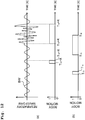
Fig. 4 is a schematic graph depicting an aspect of variation in load values detected by the load detectors in both a resting period when a subject only respires and a body motion period when the subject is performing a body motion. -
Fig. 5(a) is an illustrative view conceptionally depicting an aspect where the center of gravity of the subject oscillates or vibrates in a body axis direction of the subject according to the respirations of the subject. -
Fig. 5(b) is a graph depicting an example of a respiratory waveform drawn on the basis of the oscillation of the center of gravity of the subject according to the respirations of the subject. -
Fig. 6 is an illustrative view for explaining an example of specific method for determining the body motion with a body motion determining unit. -
Fig. 7 is an illustrative view for explaining an exemplary method for estimating the respiratory rate of the subject on the basis of the respiratory waveform. -
Fig. 8 is an illustrative view for explaining a specific example of a respiratory rate estimating step performed by a respiratory rate estimating unit. -
Fig. 9 is a block diagram depicting a configuration of a biological state monitoring system according to a second embodiment of the present invention. -
Fig. 10 is a flow chart depicting a method for estimating the respiratory rate by using the biological state monitoring system according to the second embodiment of the present invention. -
Fig. 11 is a flow chart depicting sub-steps, in the respiratory rate estimating step of the second embodiment, for varying the contents of an estimated value to be outputted on the basis of whether or not the subject's body motion is a twitch. -
Figs. 12(a) and 12(b) are illustrative views for explaining a step for performing an adjustment of the estimated value of the respiratory rate to be outputted by the respiratory rate estimating unit, with reference to a determination result of a twitch determining unit. -
Fig. 13 is a block diagram depicting an overall configuration of a bed system according to a modified embodiment of the present invention. - Explanations will be made on a biological
state monitoring system 100 according to a first embodiment of the present invention (Fig. 1 ), with an example of using the system together with a bed BD (Fig. 2 ) to estimate a respiratory rate of a subject S on the bed BD. - As depicted in
Fig. 1 , the biologicalstate monitoring system 100 of the first embodiment primarily has aload detecting unit 1, a control unit (controller) 3, and astorage unit 4. Theload detecting unit 1 and thecontrol unit 3 are connected via an A/D converting unit 2. Thecontrol unit 3 is further connected to adisplay unit 5, a notifyingunit 6, and aninput unit 7. - The
load detecting unit 1 includes fourload detectors load detectors 4829020 4002905 load detectors D converting unit 2 by way of wiring or wirelessly. - As depicted in
Fig. 2 , the fourload detectors 11 to 14 of theload detecting unit 1 are arranged respectively under casters C1, C2, C3, and C4 fitted on the lower ends of legs BL1, BL2, BL3, and BL4 at the four corners of the bed BD used by the subject S. - The A/
D converting unit 2 includes an A/D convertor connected respectively to theload detecting unit 1 and thecontrol unit 3 by way of wiring or wirelessly, to convert analog signals fed from theload detecting unit 1 to digital signals. - The
control unit 3 is a dedicated or general-purpose computer inside which a standarddeviation calculating unit 31, a respiratory waveform drawing unit 32 (respiratory waveform calculating unit; respiratory waveform obtaining(acquiring) unit), a bodymotion determining unit 33, and a respiratory rate estimating unit 34 (respiratory rate determining unit; respiratory rate calculating unit) are constructed. - The
storage unit 4 is a storage device for storing data used in the biologicalstate monitoring system 100 and, for example, a hard disk (magnetic disk) can be used for that purpose. - The
display unit 5 is monitor such as a liquid crystal monitor or the like for displaying information outputted from thecontrol unit 3 to users of the biologicalstate monitoring system 100. - The notifying
unit 6 includes a device to auditorily perform a predetermined notification on the basis of the information fed from thecontrol unit 3, such as a speaker, for example. - The
input unit 7 is an interface for performing predetermined inputs for thecontrol unit 3, which may be a keyboard and a mouse. - An explanation will be made on an operation of estimating (determining) the respiratory rate of the subject on the bed by using the biological
state monitoring system 100 of such kind. - As depicted in the flow chart of
Fig. 3 , estimation of the respiratory rate of the subject performed by using the biologicalstate monitoring system 100 includes a load detecting step S11 for detecting the load of a subject S, a standard deviation calculating step S12 for calculating a standard deviation showing the degree of variation of the detected load, a respiratory waveform drawing step S13 for drawing a respiratory waveform of the subject on the basis of the detected load, a body motion determining step S14 for determining the body motion of the subject by using the standard deviation found in the standard deviation calculating step S12, and the amplitude of the respiratory waveform drawn in the respiratory waveform drawing step S13, a respiratory rate estimating step S15 for estimating and outputting the respiratory rate of the subject on the basis of the respiratory waveform drawn in the respiratory waveform drawing step S13, and a display step S16 for displaying the outputted respiratory rate. - In the load detecting step S11, the
load detectors load detectors 11 to 14 arranged respectively under the legs BL1 to BL4 of the bed BD at the four corners. The load of the subject S is detected dispersively by the four load detectors. - Each of the
load detectors 11 to 14 detects the load (or variation of load), and outputs the result as an analog signal to the A/D converting unit 2. The A/D converting unit 2 converts the analog signal into a digital signal through a sampling period of 5 milliseconds, for example, and then outputs the digital signal (to be referred to below as "load signal") to thecontrol unit 3. Hereinafter, the term "load signals s1, s2, s3, and s4" will be used to refer respectively to the load signals obtained in the A/D converting unit 2 by converting the analog signals outputted from theload detectors - In the standard deviation calculating step S12, the standard
deviation calculating unit 31 calculates standard deviations σ1, σ2, σ3, and σ4 (moving standard deviations) of a sampling value included in a predetermined sampling period (5 seconds for example) for each of load signals s1, s2, s3, and s4. The calculation may be performed at any time (or continuously), with the sampling period of, for example, past 5 seconds. - The standard deviation denotes the magnitude of variation(dispersion) of the sampling value. Thus, as depicted in
Fig. 4 , the standard deviations σ1 to σ4 become small during a period PER1 in which the subject S is resting on the bed BD and there is a small magnitude of variation in the load signals s1 to s4. On the other hand, the standard deviations σ1 to σ4 become large during a period PER2 in which the subject S is moving his/her body (in which there is a body motion arising in the subject S) and there is a large magnitude of variation in the load signals s1 to s4. - Therefore, during a period when there is a body motion arising in the subject S, the standard deviations σ1 to σ4 have larger values in comparison to a period when there is no body motion arising in the subject S.
- In the present specification and in the present invention, the term "body motion" refers to any motion of the subject's head, torso (trunk, body-trunk), and/or four limbs. The body motion does not include motions of internal organs, blood vessels and the like along with the respirations, heartbeats, and the like. As an example, the body motion can be classified into a large body motion along with the motion of the subject S in the torso (trunk, body-trunk), and a small body motion along with the motion of the subject only in the four limbs, the head, and/or the like. One example of the large body motion is turn-over, sit-up or get-up, or the like, whereas one example of the small body motion is, a motion of the hands, the feet, the head or the like during sleep. When heartbeats, respirations and body motions arise in the subject, the load signals s1 to s4 fed from the
load detectors 11 to 14 vary accordingly. The magnitude of variation increases in the order of the variation due to the heartbeats of the subject S, the variation due to the respirations of the subject S, the variation due to the small body motion of the subject S, and the variation due to the large body motion of the subject S. - Note that in the determination of a body motion of the subject described in the present specification and in the present invention, the magnitude of variation in the load signals s1 to s4 due to the heartbeats of the subject S is so small as neglectable. Therefore, in the present specification and in the present invention, the term "the subject only (merely) respires (or the subject merely performs a respiration)", the load values and the load signals "vary due only to the respiration(s)", and the like are used to mean that the subject has no body motion, and the load values and the load signals show no variation due to the body motion, but not to mean that the subject does not have heartbeats, the load values and the load signals do not include the variation due to the heartbeats, etc.
- In the respiratory waveform drawing step S13, the respiratory waveform drawing unit 32 (respiratory waveform calculating unit; respiratory waveform obtaining(acquiring) unit) draws a respiratory waveform of the subject S on the basis of the load signals s1 to s4.
- The respiration of human is performed by moving the chest and the diaphragm to expand and shrink the lungs. In this context, when the air is inhaled (or an inspiration is performed), i.e., when the lungs are expanded, the diaphragm is lowered downwardly, and the internal organs are also moved downwardly. On the other hand, when the air is expired (or an expiration is performed), i.e., when the lungs are shrunk, the diaphragm is raised upwardly, and the internal organs are also moved upwardly. As disclosed in the specification of Japanese Patent No.
6105703 - In the present specification and in the present invention, the term "respiratory waveform (respiration waveform)" refers to a waveform showing an aspect of the oscillation (vibration) of the subject's center of gravity oscillating (vibrating) in the subject's body axis direction due to the subject's respirations, by plotting the aspect on the temporal axis. One period of the respiratory waveform corresponds to one respiration of the subject (one inspiration and expiration). The amplitude of the respiratory waveform is affected by the subject's (physical) frame (build, physique) and/or respiratory depth. In particular, for example, if the subject has a large frame or the subject performs a deep respiration, then the amplitude becomes large, whereas if the subject has a small frame or the subject performs a shallow respiration, then the amplitude becomes small.
- The respiratory
waveform drawing unit 32 draws, in particular, the respiratory waveform in the following manner. - First, the respiratory
waveform drawing unit 32 calculates the position of the center of gravity G of the subject S at each sampling time on the basis of the load signals s1 to s4 fed from theload detecting unit 1. As depicted inFig. 5(a) , the center of gravity G of the subject S oscillates in the direction of the body axis SA of the subject S in accordance with or due to the respiration of the subject S. - Next, the respiratory
waveform drawing unit 32 draws a respiratory waveform BW (Fig. 5(b) ) by way of plotting, on the vertical axis of a graph, the distance between the positions obtained by projecting the position of the center of gravity G at each time on the body axis SA, and the oscillation center of oscillation of the center of gravity G according to the respiration. The direction of the vertical axis of the graph matches the direction of the body axis SA. The horizontal axis of the graph shows time. - Note that it is not necessary for the respiratory
waveform drawing unit 32 to actually draw the respiratory waveform but it is possible to only obtain data indicating the respiratory waveform. - In the body motion determining step S14, the body
motion determining unit 33 uses the standard deviations σ1 to σ4 calculated in the standard deviation calculating step S12 and the amplitude of the respiratory waveform BW drawn in the respiratory waveform drawing step S13, to determine whether or not there is a body motion arising in the subject S (whether or not the subject S has a body motion). - The determination is performed in the following manner in particular for example.
- First, the body
motion determining unit 33 detects the peaks for the respiratory waveform BW drawn in the respiratory waveform drawing step S13, and calculates the difference between the minimum value over the period between the latest peak pn and the previous peak pn-1, and the latest peak pn, as the latest amplitude An of the respiratory waveform BW (Fig. 5(b) ). Then, the bodymotion determining unit 33 finds an average amplitude AAVn which is a simple average (value) of the amplitude An and the amplitudes An-1, An-2, ... which are calculated before the amplitude An. While an arbitrary number of amplitudes An can be used for calculating the average amplitude AAVn, as one example, the number may be such as obtained in a sampling period of 5 seconds or so. - Note that in order to confirm that the respiratory waveform BW, which is involved in calculating the amplitudes An, An-1, An-2, ... and the average amplitude AAVn, is the respiratory waveform obtained from a resting period (during which the subject only respires (performs respirations) without body motion arising), (i.e., in order to confirm that there is no error included due to the movement of the center of gravity because of some body motion), a comparison may be made between a threshold value σ0 and either a simple average σAV of the standard deviations σ1 to σ4 or any one of the standard deviations σ1 to σ4. The threshold value σ0 is set at such a small value as able to reliably determine that there is no body motion arising in the subject S as long as the simple average σAV or any one of the standard deviations σ1 to σ4 is smaller than that value (conversely, even if the simple average σAV or any one of the standard deviations σ1 to σ4 is not smaller than that value, it is still possible that there is no body motion arising in the subject S).
- Next, the body
motion determining unit 33 finds normalized standard deviations σs1 to σs4 by the following Formula (Equation) 1.
- Then, the body
motion determining unit 33 finds a simple average σsAV of the calculated normalized standard deviations σs1 to σs4 and, based on a comparison between the simple average σsAV and a predetermined threshold value σsTH, determines whether or not there is a body motion arising in the subject S (whether or not the subject S has a body motion). In particular, for example, if the simple average σsAV is larger than or equal to the threshold value σsTH, then it is determined that there is a body motion arising in the subject S (the subject S has a body motion), whereas if the simple average σsAV is smaller than the threshold value σsTH, then it is determined that there is no body motion arising in the subject S (the subject S has no body motion). - During a period when it is determined that there is no body motion arising in the subject S, the body
motion determining unit 33 calculates the latest amplitude An for each one period of the respiratory waveform BW on the basis of the respiratory waveform BW acquired by the respiratorywaveform drawing unit 32. Then, using the average amplitude AAVn calculated anew by using the value of the calculated latest amplitude An, and the values of the standard deviations σ1 to σ4 calculated at each sampling time (as an example, every 5 milliseconds), the bodymotion determining unit 33 calculates, successively, the normalized standard deviations σs1 to σs4 by theFormula 1 and calculates the simple average σsAV. - Determining whether or not there is a body motion arising in the subject S is performed by the successive comparisons between the predetermined threshold value σsTH and the simple average σsAV calculated successively in the above manner.
- After it is determined as a result of the determination that there is a body motion arising in the subject S, the body
motion determining unit 33 ceases to update the average amplitude AAVn and continues to calculate the simple average σsAV using the average amplitude AAvn having been calculated by this point. Then, based on a comparison between the calculated simple average σsAV and the threshold value σsTH, the bodymotion determining unit 33 continues to determine whether or not there is a body motion arising in the subject S. This is because during a period when there is a body motion arising in the subject S, the amplitude and period of the respiratory waveform BW vary greatly due to the influence of the body motion, and thereby it is difficult to calculate a new amplitude An and the average amplitude AAVn without error. - Next, if it is determined again that there is no body motion arising in the subject S, then based on the respiratory waveform BW acquired by the respiratory
waveform drawing unit 32, the bodymotion determining unit 33 calculates the value of the latest amplitude An and, using the same, calculates the average amplitude AAVn anew. Then, the bodymotion determining unit 33 calculates the simple average σsAV using the latest average amplitude AAVn and, based on a comparison between the calculated simple average σsAV and the predetermined threshold value σsTH, the bodymotion determining unit 33 continues to determine whether or not there is a body motion arising in the subject S. - Referring to
Fig. 6 , a particular example of this step will be explained. - As depicted in
Fig. 6 , if a peak P1 of the respiratory waveform BW and the latest amplitude A1 are obtained at the time T1, then for the period from the time T1, the bodymotion determining unit 33 uses the average amplitude AAV1 which is the simple average of the amplitude A1 and the amplitudes A0, A-1, ... (all not shown) obtained right therebefore, to calculate successively the normalized standard deviations σs1 to σs4 and the simple average σsAV (to be referred to here as σsAV (AAV1)); and determines whether or not there is a body motion arising in the subject S, based on a comparison between the simple average σsAV (AAV1) and the threshold value σsTH. - Next, if another peak P2 of the respiratory waveform BW and the latest amplitude A2 are obtained at the time T2, then for the period from the time T2, the body
motion determining unit 33 uses the average amplitude AAV2 calculated by using the amplitude A2, to calculate successively the normalized standard deviations σs1 to σs4 and the simple average σsAV (to be referred to here as σsAV (AAV2)); and determines whether or not there is a body motion arising in the subject S, based on the comparison between the simple average σsAV (AAV2) and the threshold value σsTH. - At the time T21, if there is a body motion arising in the subject S, then the body
motion determining unit 33 determines that there is a body motion arising in the subject S on the basis of the simple average σsAV (AAV2) being equal to or larger than the threshold value σsTH. Then, after that, for the period when the simple average σsAV (AAV2) is equal to or larger than the threshold value σsTH, the bodymotion determining unit 33 continues to determine the body motion using the simple average σsAV (AAV2). - At the time T22, if the body motion has come to an end in the subject S, then the body
motion determining unit 33 determines that there is no body motion arising in the subject S on the basis of the simple average σsAV (AAV2) being smaller than the threshold value σsTH. After that, the bodymotion determining unit 33 continues to determine the body motion using the simple average σsAV (AAV2) until the latest amplitude An of the respiratory waveform BW is obtained and the latest average amplitude AAVn is calculated again. - The body
motion determining unit 33 uses the amplitude An (average amplitude AAVn) of the respiratory waveform to normalize the values of the standard deviations σ1 to σ4. The reason therefor is as follows. - As described above, generally speaking, the values of the standard deviations σ1 to σ4 become larger during a period when there is a body motion arising in the subject S. Therefore, it is conceivable to determine whether or not there is a body motion arising in the subject S by way of comparison between the values of the standard deviations σ1 to σ4 and a predetermined threshold value.
- However, according to the discovery and knowledge of the present inventors, for a subject who has a large frame, the values of the standard deviations σ1 to σ4 may still be comparatively large even during a period of only performing respirations without the body motion because the movement of his/her internal organs due to the respirations is also large. Further, even for a subject who does not have a large frame, the values may still become large if, for example, the subject performs a deep respiration. Hence, if the body motion determination is performed by comparing the values of the standard deviations σ1 to σ4 to a predetermined threshold value, in such a case, even though there is no body motion arising in the subject, a mistaken determination may be made to give the incorrect result that there is a body motion arising in the subject.
- On the other hand, if the respiratory waveform is focused on, then as described earlier on, the amplitude of the respiratory waveform is affected by the subject's frame and/or respiratory depth; therefore, if the subject has a large frame or the subject performs a deep respiration, then the amplitude becomes large, whereas if the subject has a small frame or the subject performs a shallow respiration, then the amplitude becomes small.
- That is, by dividing the values of the standard deviations σ1 to σ4 by the average amplitude AAVn of the respiratory waveform BW to perform the normalization, it is possible to reduce (compensate; correct) the influence on the values of the standard deviations σ1 to σ4, exerted by the subject's frame and/or respiratory depth. Then, by using the normalized standard deviations σs1 to σs4 obtained through such normalization to determine the body motion, it is possible to raise the precision of determining the body motion.
- In the respiratory rate estimating step S15, the respiratory rate estimating unit 34 (the respiratory rate determining unit) estimates (determines) the respiratory rate of the subject S on the basis of the respiratory waveform BW of the subject S drawn in the respiratory waveform drawing step S13, and outputs the estimated (determined) respiratory rate to the
display unit 5. - In particular, the respiratory
rate estimating unit 34 estimates the respiratory rate on the basis of the respiratory waveform BW by the following method. - The respiratory
rate estimating unit 34 detects peaks in predetermined periods for the respiratory waveform BW drawn in the respiratory waveform drawing step S13. Then, when a new peak is detected, the respiratoryrate estimating unit 34 finds distances (to be referred to below as inter-peak distances t) between any two adjacent peaks of the plurality of peaks included between a first time point at which the new peak is detected and a second time point before (preceding) the first time point by a predetermined time period (25 seconds for example; to be referred to below as "sampling time period for estimation" as appropriate). -
Fig. 7 depicts one example of the respiratory waveform BW included in the sampling time period for estimation over 25 seconds with peaks p1 to p6 of the respiratory waveform BW, and inter-peak distances t1 to t5 between the peaks p1 to p6. - Next, the respiratory
rate estimating unit 34 finds an average value tAV of the plurality of inter-peak distances t by the followingFormula 2.
- Herein, N is the number of peaks of the respiratory waveform BW included in the sampling time period for estimation. The average value tAV approximately corresponds to the average value of the respiratory periods of the subject S during the sampling time period for estimation.
- Thereafter, the respiratory
rate estimating unit 34 calculates an estimated value R of the respiratory rate over one minute of the subject S by the followingFormula 3. Then, the calculated estimated value R is outputted to thedisplay unit 5 as the estimated respiratory rate.
- Further, the respiratory
rate estimating unit 34 of this embodiment adjusts the value of the respiratory rate for output according to whether or not the subject S has a body motion. This adjustment will be explained as follows. - The respiratory
rate estimating unit 34 successively calculates the estimated value R of the respiratory rate by using theFormulas motion determining unit 33 determines that the subject S does not have a body motion and in a period (body motion period) when the bodymotion determining unit 33 determines that the subject S has a body motion. - Then, in the resting period (excluding a predetermined period after the transition (shifting) from the body motion period to the resting period, as will be described later on), the calculated estimated values R are outputted successively to the
display unit 5 as the estimated respiratory rates. - On the other hand, in the body motion period, the respiratory
rate estimating unit 34 outputs the estimated value (first estimated value) R calculated right before the transition (shifting) from the resting period to the body motion period, that is, the estimated value R calculated last in the resting period right therebefore, instead of the estimated value R of the respiratory rate calculated successively by using theFormulas display unit 5 as the estimated respiratory rate. - Further, when a transition from a first resting period to a body motion period occurred and then a transition from the body motion period to a second resting period occurred, in a predetermined period after the transition from the body motion period to the second resting period, the respiratory
rate estimating unit 34 outputs the value outputted in the preceding body motion period, that is, the estimated value R calculated right before the transition from the first resting period to the body motion period, to thedisplay unit 5 as the estimated respiratory rate, instead of the estimated value R of the respiratory rate calculated successively by using theFormulas - Then, after detecting two peaks of the respiratory waveform BW in the second resting period, the respiratory
rate estimating unit 34 finds (obtains) the inter-peak distance t between those two peaks, and uses the value of the inter-peak distance t as the value of the average value tAV to calculate the estimated value R of the respiratory rate by theFormula 3. Then, the respiratoryrate estimating unit 34 outputs the estimated value R calculated anew to thedisplay unit 5 as the estimated respiratory rate, instead of the value outputted fixedly in the body motion period and the following predetermined period, that is, the estimated value R calculated right before the transition from the first resting period to the body motion period. - In the same manner, at the time points at which three and four peaks of the respiratory waveform BW have been detected, the respiratory
rate estimating unit 34 obtains the inter-peak distances t between two adjacent peaks of the three and four peaks, respectively, to calculate the estimated value R of the respiratory rate by theFormula 3 by using a simple average (value) of those obtained inter-peak distances t as the value of the average value tAV. Then, the respiratoryrate estimating unit 34 outputs the calculated values as the estimated respiratory rate to thedisplay unit 5. Then, after the sampling time period for estimation (25 seconds for here) has elapsed after (since) the transition from the body motion period to the second resting period, the respiratoryrate estimating unit 34 restarts calculating the average value tAV by using theabove Formula 2 to calculate the estimated value R by applying the calculated average value tAV to theabove Formula 3, and output the calculated value to thedisplay unit 5 as the estimated respiratory rate. - A specific example of this step will be explained, using
Fig. 8 . - As depicted in
Fig. 8 , after detecting the peak P4 of the respiratory waveform BW at the time T4 included in the resting period, the respiratoryrate estimating unit 34 calculates the estimated value R of the respiratory rate by theabove Formulas rate estimating unit 34 calculates the estimated values R of the respiratory rate by theabove Formulas - Next, if a body motion arises in the subject S at the time T61, then the respiratory
rate estimating unit 34 switches the estimated value of the respiratory rate for output from the estimated value R calculated anew by using theabove Formulas motion determining unit 33 having determined that the subject S has a body motion. Then, during the period when the bodymotion determining unit 33 determines that the body motion is arising in the subject S (the subject S has the body motion), that is, during the body motion period, the respiratoryrate estimating unit 34 keeps outputting the respiratory rate R6 as the estimated respiratory rate. - Further, after the body motion of the subject S comes to an end at the time T62 such that the body
motion determining unit 33 determines that there is no body motion arising in the subject S (that is, after returning to a resting period), the respiratoryrate estimating unit 34 also keeps outputting the estimated value calculated right before the time T61 (equal to the respiratory rate R6) as the estimated respiratory rate, through a predetermined period, instead of the estimated value R calculated anew by using theabove Formulas - Then, after detecting the second peak P8 after the body motion of the subject S comes to an end at the time T8, the respiratory
rate estimating unit 34 finds the inter-peak distance t8 between the first peak P7 and the peak P8 after the body motion of the subject S comes to the end. Then, using the inter-peak distance t8 as the average value tAV, the respiratoryrate estimating unit 34 calculates the estimated value R of the respiratory rate by theFormula 3, and outputs the newly calculated estimated value R as the estimated respiratory rate instead of the value outputted fixedly after the time T61 (the respiratory rate R6). Here, suppose that the respiratory rate R8 is outputted. - After detecting the third peak P9 after the body motion of the subject S comes to an end at the time Tg, the respiratory
rate estimating unit 34 finds the inter-peak distance tg between the second peak P8 and the peak P9 after the body motion of the subject S comes to the end. Then, using a simple average of the inter-peak distance t8 and the inter-peak distance t9 as the average value tAV, the respiratoryrate estimating unit 34 calculates the estimated value R of the respiratory rate by theFormula 3, and outputs the calculated value as the estimated respiratory rate. Here, suppose that the respiratory rate R9 is outputted. - In the same manner, after detecting the fourth peak P10 and the fifth peak P11 after the body motion of the subject S comes to an end at the times T10 and T11, the respiratory
rate estimating unit 34 finds the inter-peak distance t10 between the peak Pg and the peak P10, and the inter-peak distance t11 between the peak P10 and the peak P11. Then, using the simple average of what has already been obtained in the inter-peak distances t8 to t11 as the average value tAV, it calculates the estimated value R of the respiratory rate by theFormula 3, and outputs the calculated value as the estimated respiratory rate. Here, suppose that the respiratory rates R10 and R11 are outputted. - Then, after 25 seconds, which corresponds to the sampling time period for estimation, has elapsed since the time T62, the respiratory
rate estimating unit 34 restarts calculating the average value tAV by using theabove Formula 2, to calculate the estimated value R of the respiratory rate by applying the calculated average value tAV to theabove Formula 3. Then, it outputs the calculated value to thedisplay unit 5 as the estimated respiratory rate. - The following statement is the reason why the respiratory
rate estimating unit 34 outputs the estimated value R of the respiratory rate, calculated right before the transition from the resting period to the body motion period, as the estimated value of the respiratory rate of the subject S instead of the estimated value R calculated, in the body motion period and the predetermined initial period of the following resting period. - As depicted in
Fig. 8 , there are detected peaks in the respiratory waveform BW during the body motion period, too. However, as seen in the waveform depicted inFig. 8 , the respiratory waveform BW is affected and disturbed by the body motion of the subject S whereby the period of the respiratory waveform BW is also varying. Therefore, the inter-peak distances found on the basis of the peaks of the respiratory waveform BW in the body motion period do not reflect the respiratory period by their values. If the sampling time period for estimation includes a body motion period, then the average value tAV found by theFormula 2 is affected by the inter-peak distances which do not reflect the respiratory period in this manner. Therefore, there is also a high possibility for the estimated value R of the respiratory rate calculated by using theFormula 3 to deviate from the actual respiratory rate of the subject. - Therefore, in the body motion period and the predetermined initial period in the resting period following the body motion period, during which the body motion period is included inevitably in the sampling time period for estimation, the respiratory
rate estimating unit 34 outputs the estimated value R calculated right before the transition from the resting period to the body motion period as the estimated value for those periods, instead of the estimated value R calculated anew. By virtue of this, reliability is maintained for the estimated value of the respiratory rate to offer the user of the biologicalstate monitoring system 100. - Note that the respiratory
rate estimating unit 34 may cease to detect the peaks of the respiratory waveform BW, cease to calculate the inter-peak distances, and cease to calculate the estimated values R using theFormulas - In this embodiment, at the time point by which two peaks of the respiratory waveform BW of the resting period have been detected, the estimated value R is calculated by using the inter-peak distance between those peaks, and the calculated value is outputted. According to this method, after the transition from the body motion period to the resting period, it is possible to restart calculating and outputting the estimated value R of the respiratory rate with exclusion of the influence of disturbance of the respiratory waveform BW in the body motion period, without waiting for the passage of the time equivalent to the sampling time period for estimation. However, after an end of the body motion, it is allowable to keep outputting the estimated value R calculated right before the transition to the body motion period, until the lapse of the time almost equal to the sampling time period for estimation.
- In the display step S16, the
control unit 3 causes thedisplay unit 5 to display the respiratory rate (estimated value) of the subject S outputted in the respiratory rate estimating step S15. Further, in the display step S16, the notifyingunit 6 may be used to perform a notification in addition to or instead of the display using thedisplay unit 5. In this case, for example, when the respiratory rate of the subject S reaches a predetermined set value, a notification sound may be emitted to notify the nurses, caregivers and/or others who are the users of the biologicalstate monitoring system 100. - The effects of the biological
state monitoring system 100 according to this embodiment are summarized as follows. - In a case that the subject S has a body motion, then the respiratory
rate estimating unit 34 included in the biologicalstate monitoring system 100 of this embodiment outputs the estimated value calculated right before an occurrence of the body motion, during a period in which the body motion is kept and during a predetermined period succeeding an end of the body motion, as the estimated value of the respiratory rate for those periods. - Therefore, even when the subject S has a body motion, it is possible for the biological
state monitoring system 100 of this embodiment to suppress the influence of the body motion, thereby outputting the estimated value of the respiratory rate of the subject S with high reliability. - The respiratory
rate estimating unit 34 included in the biologicalstate monitoring system 100 of this embodiment restarts, at the point of detecting two peaks of the respiratory waveform BW after the transition from the body motion period to the resting period, calculating the estimated value of the respiratory rate by using the inter-peak distance between those peaks. Therefore, it is possible for the biologicalstate monitoring system 100 of this embodiment to release the respiratory rate displayed on thedisplay unit 5 from the state fixed at the value estimated right before a body motion, at an earlier timing after the end of the body motion. - The biological
state monitoring system 100 of this embodiment uses theload detectors 11 to 14 arranged under the legs BL1 to BL4 of the bed BD to determine whether or not the subject S has a body motion. Therefore, it is not necessary to attach any measuring device to the body of the subject S so that the subject S will not feel discomfort and a sense of incongruity. - Next, an explanation will be made on a biological
state monitoring system 200 according to a second embodiment of the present invention. - In the biological
state monitoring system 100 of the above first embodiment, the respiratoryrate estimating unit 34 fixes the estimated value of the respiratory rate of the subject S for output at the estimated value (the first estimated value) calculated right before a body motion period, during the body motion period and the like when a disturbance arises in the respiratory waveform due to the body motion of the subject S. In such a manner, the biologicalstate monitoring system 100 prevents degradation of the reliability of the estimated value of the respiratory rate due to the influence of disturbance of the respiratory waveform. - In this context, it is known that a motion of muscle spasm which is called a twitch (a jerk) may occur in a person during REM sleep. Such a twitch is also a kind of body motion. The present inventors have made researches on the influence of a twitch on biological state monitoring and obtained the discovery and knowledge that even if the subject S performs a twitch, the twitch will not give rise to a large disturbance in the respiratory waveform. It is conceived that this is because the influence of the twitch which is a body motion over a short duration time (continuance time) is eliminated or reduced in the calculating process or filtering process for obtaining the respiratory waveform. On the other hand, according to the discovery and knowledge of the present inventors, even if the body motion is a twitch, the body motion determining unit still determines that a body motion has arisen.
- The biological
state monitoring system 200 of the second embodiment is based on the above discovery and knowledge of the present inventors, and configured not to perform estimation fixing (estimated value fixing), performed by the respiratoryrate estimating unit 34 of the biologicalstate monitoring system 100 of the first embodiment, even when the body motion determining unit determines that the subject has the body motion, provided that the body motion is a twitch. By virtue of this, the biological state monitoring system of the second embodiment can output the estimated value of the respiratory rate of the subject with even higher reliability. - The biological
state monitoring system 200 of the second embodiment (Fig. 9 ) has the same configuration as the biologicalstate monitoring system 100 of the first embodiment except for the aspect of including atwitch determining unit 35 configured to determine whether or not the body motion of the subject is a twitch. Explanation will be omitted for any configuration common to the biologicalstate monitoring systems twitch determining unit 35 operates will be described latter on. - As depicted in the flow chart of
Fig. 10 , estimation of the respiratory rate of the subject performed by using the biologicalstate monitoring system 200 includes a load detecting step S21 for detecting the load of the subject S, a standard deviation calculating step S22 for calculating the standard deviation showing the degree of variation of the detected load, a respiratory waveform drawing step S23 for drawing the respiratory waveform of the subject on the basis of the detected load, a body motion determining step S24 for determining the body motion of the subject by using the standard deviation found in the standard deviation calculating step S22, and the amplitude of the respiratory waveform drawn in the respiratory waveform drawing step S23, a twitch determining step S25 for determining whether or not the body motion of the subject S is a twitch, a respiratory rate estimating step S26 for estimating and outputting the respiratory rate of the subject on the basis of the respiratory waveform drawn in the respiratory waveform drawing step S23, and a display step S27 for displaying the outputted respiratory rate. - The load detecting step S21, the standard deviation calculating step S22, the respiratory waveform drawing step S23, the body motion determining step S24, and the display step S27 are substantially (practically) the same, respectively, as the load detecting step S11, the standard deviation calculating step S12, the respiratory waveform drawing step S13, the body motion determining step S14, and the display step S16 which are carried out by the biological
state monitoring system 100 of the first embodiment. Therefore, explanations therefor will be omitted. - In the twitch determining step S25, the
twitch determining unit 35 determines whether or not the body motion arising in the subject S is a twitch on the basis of the determination result of the bodymotion determining unit 33. In particular, the determination is performed by the following method. - The
twitch determining unit 35 receives the determination result of body motion from the bodymotion determining unit 33 and, at the point of change from absence of body motion to presence of body motion in the determination result, starts measuring the length of time. Then, thetwitch determining unit 35 obtains, by a measurement, a length of time (duration, duration time) from the time point at which the determination result of the bodymotion determining unit 33 changes from absence of body motion to presence of body motion until the time point at which the determination result return to absence of body motion, and compares the found duration time to a predetermined threshold value Dth. - As a result of the comparison, in a case that the duration of a certain body motion is shorter than the threshold value Dth, then this body motion is determined as a twitch of which duration is short. On the other hand, in a case that the duration of a certain body motion is longer than the threshold value Dth, then this body motion is determined as not a twitch but a body motion of which duration is long.
- The threshold value Dth used for the determination may be set as appropriate on the basis of the duration of an ordinary twitch. Further, the threshold value Dth may be set by considering such a time, as extending until a vibration, which arose in the bed and the like from the influence of a twitch, comes to an end. Alternatively, the threshold value Dth may be set by considering other factors with an actual installation of the system. The threshold value Dth may be about 0.5 seconds to 6 seconds, in particular for example.
- In the present specification and in the present invention, a body motion whose duration is shorter than a predetermined time period or, in other words, a body motion of which occurrence affects the body motion determination for a time period shorter than a predetermined time period (0.5 to 6 seconds for example) is regarded as a twitch.
- In the respiratory rate estimating step S26, the respiratory
rate estimating unit 34 calculates and outputs the estimated value of the respiratory rate of the subject S, on the basis of the respiratory waveform BW drawn by the respiratorywaveform drawing unit 32, the determination result given by the bodymotion determining unit 33, and the determination result given by thetwitch determining unit 35. - The respiratory
rate estimating unit 34 receives the respiratory waveform BW from the respiratorywaveform drawing unit 32 and the determination result from the bodymotion determining unit 33, and use these two items with a delay of a predetermined time X. The reason for such a delay will be described later on. - As depicted in the flow chart of
Fig. 11 , the respiratoryrate estimating unit 34 first determines whether or not there is a body motion arising in the subject S on the basis of the determination result by the body motion determining unit 33 (S261,Fig. 11 ). Then, if there is no body motion arising in the subject S (S261: No), then the respiratoryrate estimating unit 34 outputs the estimated values R calculated successively anew by theFormulas display unit 5 in sequence as the estimated respiratory rate (S263,Fig. 11 ). - If there is a body motion arising in the subject S (S261: Yes), then the respiratory
rate estimating unit 34 carries out the following process, which is different from the respiratory rate estimating step S15 of the first embodiment. - At the point when the determination result by the body
motion determining unit 33 changes from absence of body motion to presence of body motion, the respiratoryrate estimating unit 34 first determines whether or not the body motion is a twitch on the basis of the determination result by the twitch determining unit 35 (S262,Fig. 11 ). - Then, if the body motion is not a twitch (S262: No), the respiratory
rate estimating unit 34 outputs the estimated value (the first estimated value) R, calculated right before the transition from the resting period to the body motion period, to thedisplay unit 5 as the estimated respiratory rate, instead of the estimated value R of the respiratory rate calculated successively by using theFormulas 2 and 3 (S264,Fig. 11 ), like the process in the respiratory rate estimating step S15 of the first embodiment performed when there is a body motion arising in the subject S. The process after the subsequent shift from the body motion period to the resting period is also the same as the process performed in the respiratory rate estimating step S15 of the first embodiment. - On the other hand, if the body motion is a twitch (S262: Yes), then in the same manner as for the resting period, the respiratory
rate estimating unit 34 successively outputs the estimated values R calculated anew by using theFormulas display unit 5 as the estimated respiratory rates (S263,Fig. 11 ). That is, the respiratoryrate estimating unit 34 is configured such that, even if the bodymotion determining unit 33 determines that there is a body motion arising in the subject S, provided that thetwitch determining unit 35 determines that the body motion is a twitch, the respiratoryrate estimating unit 34 carries out the same process as for the resting period without regarding the period of the arising body motion as a body motion period. - Note that as described earlier on, the respiratory
rate estimating unit 34 uses the respiratory waveform BW received from the respiratorywaveform drawing unit 32 and the body motion determination result received from the bodymotion determining unit 33, with a delay of the predetermined time X. Therefore, if the predetermined time X is larger than the threshold value Dth, then at the point when the determination result by the bodymotion determining unit 33 changes from absence of body motion to presence of body motion in the process carried out by the respiratoryrate estimating unit 34, thetwitch determining unit 35 is already finished with the determination of whether or not the body motion is a twitch. Therefore, as described above, the respiratoryrate estimating unit 34 can determine (confirm) whether or not the body motion is a twitch at the point when the determination result by the bodymotion determining unit 33 changes from absence of body motion to presence of body motion. -
Figs. 12(a) and 12(b) will be used to explain a particular example of this process. Note that in the lower graph ofFig. 12(a) , and inFig. 12(b) , "1 " means presence of body motion and "0" means absence of body motion, on the vertical axis. - As depicted in
Fig. 12(b) , in a case that the bodymotion determining unit 33 determines that the subject S has a body motion at a time T13, then thetwitch determining unit 35 measures the duration (continuance time) from that point to a time T14 when the determination result by the bodymotion determining unit 33 returns to absence of body motion again, and compares the found duration to the threshold value Dth. Here, the threshold value Dth is 3 seconds, and the duration from the time T13 to the time T14 is 2 seconds. Therefore, thetwitch determining unit 35 determines that the body motion arising over the period from the time T13 to the time T14 is a twitch. - Then, as depicted in the lower graph of
Fig. 12(a) , after the predetermined time X (the data delay time for the respiratory rate estimating unit 34: 5 seconds or so for example) has elapsed since the time T13, that is, at the time T13 + X, the respiratoryrate estimating unit 34 determines the contents of the following process with reference to the determination result by thetwitch determining unit 35, on the basis of the determination result by the bodymotion determining unit 33 stating that there is a body motion arising in the subject S. - In this context, because the
twitch determining unit 35 has determined that the body motion arising from the time T13 to the time T14 is a twitch, even after the time T13 + X, the respiratoryrate estimating unit 34 successively outputs the estimated value R calculated anew by using theFormulas display unit 5, as the estimated respiratory rate. The estimated value indicates the state of the subject S around the time T13, and is outputted after the time T13 + X, that is, being delayed by the predetermined time X. - Note that as depicted in the upper graph of
Fig. 12(a) , during the period when there is a twitch arising in the subject S, there is no large disturbance arising in the respiratory waveform of the subject S. Therefore, even if the sampling time period for estimation contains a period when there is a twitch arising, there is still a high reliability of the estimated value R calculated anew by using theFormulas - Subsequently, if the body
motion determining unit 33 determines that there is a body motion arising in the subject S at a time T15, then thetwitch determining unit 35 restarts to measure the time from that point. Then, thetwitch determining unit 35 determines that the body motion is not a twitch at the point when the period, for which the bodymotion determining unit 33 has determined as "presence of body motion" exceeds the threshold value Dth (3 seconds in this case). In this context, it is assumed that the bodymotion determining unit 33 has determined that the body motion arising continuously from the time T15 is not a twitch, prior to the time T15 + X. - Then, at the time T15 + X, that is, after the predetermined time X has elapsed since the time T15, the respiratory
rate estimating unit 34 determines the contents of the following process with reference to the determination result by thetwitch determining unit 35 again, on the basis of the determination result by the bodymotion determining unit 33 stating that there is a body motion arising in the subject S. - In this context, because the
twitch determining unit 35 has determined that the body motion arising continuously from the time T15 is not a twitch, after the time T15 + X, the respiratoryrate estimating unit 34 outputs the estimated value R calculated right before the time T15 + X, to thedisplay unit 5 as the estimated respiratory rate. While the estimated value indicates the state of the subject S after the time T15, it is outputted after the time T15 + X with a delay of the predetermined time X. - The biological
state monitoring system 200 of the second embodiment has the following effects in addition to the effects of the biologicalstate monitoring system 100 of the first embodiment. - The biological
state monitoring system 200 of the second embodiment includes thetwitch determining unit 35 such that even if there is a body motion arising in the subject S, provided that the body motion is a twitch which exerts a small influence on calculating the estimated value of the respiratory rate, the respiratoryrate estimating unit 34 is caused to keep on outputting the estimated value R calculated anew. In this manner, the biologialstate monitoring system 200 of the second embodiment can shorten the period in which the estimated value calculated in the past resting period is outputted alternatively to a minimum (bare minimum), by determining whether or not the body motion is a twitch. Therefore, it is possible to output the estimated value of the respiratory rate of the subject with higher reliability. - Note that the respiratory
rate estimating unit 34 of the biologicalstate monitoring system 200 of the above second embodiment carries out the process for the respiratory waveform BW received from the respiratorywaveform drawing unit 32 and the body motion determination result received from the bodymotion determining unit 33, with a delay of the predetermined time X. However, without being limited to that, for example, depending on the processing contents in the system, the respiratory waveform BW may be drawn a predetermined length of time later than the body motion is determined by the bodymotion determining unit 33. In this case, even without the respiratoryrate estimating unit 34 purposely applying a delay, it is still possible for thetwitch determining unit 35 to finish the determination before the process is carried out by the respiratoryrate estimating unit 34. - It is also possible for the biological
state monitoring systems - The respiratory
rate estimating unit 34 of the biologicalstate monitoring systems rate estimating unit 34 only within the body motion period, it is still possible to suppress the influence of the body motion of the subject S to a considerable degree, thereby outputting the estimated value of the respiratory rate of the subject with high reliability. - The biological
state monitoring systems state monitoring systems - In the biological
state monitoring systems rate estimating unit 34 may estimate the respiratory rate of the subject S without using the respiratory waveform BW. - In particular, for example, the respiratory
rate estimating unit 34 calculates the respiratory rate of the subject S by carrying out the Fourier analysis on at least one of the load signals s1 to s4 corresponding to the predetermined sampling period so as to specify the peak frequency coming up in the frequency band corresponding to the respirations (from about 0.2 Hz to about 0.33 Hz because the human respiration is performed about 12 to 20 times per minute). With the specified peak frequency, it is possible to calculate (estimate) the respiratory rate of the subject S over that period. - In this case, too, if the sampling period includes a body motion period, then the reliability of the calculated respiratory rate (estimated value) of the subject S may decrease due to a variation of the load signals s1 to s4 arising from the body motion. Therefore, it is possible to raise the reliability of the estimated value of the respiratory rate by adjusting the outputted value by the same method as used by the respiratory
rate estimating unit 34 of the above embodiments. - In the biological
state monitoring systems motion determining unit 33 normalizes the standard deviations σ1 to σ4 by dividing the standard deviations σ1 to σ4 by the average amplitude AAVn to reduce (compensate; correct) the influence on the values of the standard deviations σ1 to σ4, exerted by the frame and/or respiratory depth of the subject S. However, the compensating (correcting) method by utilizing the amplitude of the respiratory waveform BW is not limited to that. In particular, for example, the standard deviations σ1 to σ4 may be normalized by way of dividing the same by the latest amplitude An of the respiratory waveform BW. - Note that, it is also possible to compensate the threshold value by using the amplitude of the respiratory waveform BW and compare the standard deviations σ1 to σ4 to the compensated threshold value, instead of compensating the standard deviations σ1 to σ4 by using the amplitude of the respiratory waveform BW and then comparing the compensated values to the threshold value. In particular, for example, in the above embodiments, instead of dividing the standard deviations σ1 to σ4 by the average amplitude AAVn, it is possible to perform a desired compensation (correction) by multiplying the predetermined threshold value by the average amplitude AAVn. In this manner, the two methods mentioned above are practically equivalent and thus it is possible to appropriately select either the standard deviations or the threshold value used in the comparison for the compensation (correction) by the amplitude of the respiratory waveform. In the present specification and in the present invention, the expression "compensating the standard deviations by the amplitude of the respiratory waveform" is termed to include compensating the threshold value by the amplitude of the respiratory waveform.
- In the biological
state monitoring systems motion determining unit 33 performs the body motion determination by the comparison between the simple average σsAV of the normalized standard deviations σs1 to σs4 and the threshold value σsTH. However, it is also possible to determine the body motion by a comparison between at least one of the normalized standard deviations σs1 to σs4 and the threshold value, a comparison between simple average values of at least two or more of the normalized standard deviations σs1 to σs4 and the threshold value, a comparison between the total value of at least two or more of the normalized standard deviations σs1 to σs4 and the threshold value, or the like. - Further, in the biological
state monitoring systems motion determining unit 33 to use a variance which is the squared standard deviation instead of the standard deviation. If the variance is normalized by the amplitude of the respiratory waveform, then the variance may be divided by the squared amplitude of the respiratory waveform. Therefore, in the present specification and in the present invention, the standard deviation is termed to include the variance. - The body
motion determining unit 33 may provide the threshold value used for the body motion determination with hysteresis. In particular, for example, with a first threshold value and a second threshold value larger than the first threshold value set in advance, under the condition that the subject S is determined as with no body motion arising therein, as far as the simple average σsAV is yet smaller than the second threshold value, the subject S is not determined as with a body motion arising therein. On the other hand, under the condition that the subject S is determined as with a body motion arising therein, even if the simple average σsAV is smaller than the second threshold value, the subject S is not determined as with no body motion arising therein, but is determined as with no body motion arising therein at the point of the simple average σsAV becoming smaller than the first threshold value. - In the biological
state monitoring systems motion determining unit 33 may determine whether or not the subject S has a body motion on the basis of a comparison between at least one of the standard deviations σ1 to σ4 and the threshold value, or a comparison between the total value or a simple average of at least two or more of the standard deviations σ1 to σ4 and the threshold value, without finding the normalized standard deviations σs1 to σs4. - In the biological
state monitoring systems motion determining unit 33 can also determine whether or not the subject S has a body motion without using the standard deviations σ1 to σ4. In particular, for example, it determines whether or not the subject S has a body motion on the basis of a movement of the center of gravity of the subject S. - As described earlier on, the center of gravity G of the subject S oscillates in the direction of the body axis SA of the subject S according to the respirations of the subject S (
Fig. 5(a) ). Further, the center of gravity G of the subject S moves according to that if the subject S has a small body motion or a large body motion. Then, the moving distance of the center of gravity G over a predetermined period increases in the ascending order of the period when the subject S only respires, the period when the subject S has a small body motion, and the subject S has a large body motion. - Therefore, the body
motion determining unit 33 can determine whether or not the subject S has a body motion by comparing a predetermined threshold value with the moving distance of the center of gravity G over a predetermined period. In particular, for example, it is possible to determine that the subject S has a small body motion if the moving distance d of the center of gravity G over a predetermined period is longer than a threshold value dth. - The biological
state monitoring systems load detectors 11 to 14 but may include only any one of the four. For example, if there are three such load detectors, then it is still possible to detect the position of the center of gravity G of the subject S on the plane of the bed BD provided that the three load detectors are not arranged on a straight line. Further, the load detectors do not need to be arranged at the four corners of the bed but may be arranged in any positions as far as they can detect the load of the subject on the bed and the variation thereof. Further, theload detectors 11 to 14 are not limited to load sensors using beam-type load cells but, for example, force sensors are also usable. - In the biological
state monitoring systems load detectors 11 to 14 are arranged respectively on the undersides of the casters C attached to the lower ends of the legs of the bed BD. However, there is no limitation thereto. Each of theload detectors 11 to 14 may be provided respectively between one of the four legs of the bed BD and the board of the bed BD. Alternatively, if each of the four legs of the bed BD can be divided into upper and lower portions, each of theload detectors 11 to 14 may be provided between the upper leg and the lower leg. Further alternatively, theload detectors 11 to 14 may be formed integral with or removable from the bed BD to construct a bed system BDS comprising the bed BD, and the biologicalstate monitoring system Fig. 13 ) . - In the biological
state monitoring systems load detecting unit 1 and the A/D converting unit 2, it is possible to provide a signal amplifying unit to amplify the load signals fed from theload detecting unit 1, and a filtering unit to eliminate the noises from the load signals. - In the biological
state monitoring systems display unit 5 may include a printer for printing out the information indicating the biological state (respiratory rate, presence or absence of body motion, etc.), a simplified visual display means such as lamps indicating the biological state (respiratory rate, presence or absence of body motion, etc.), and/or the like, instead of the monitor or in addition to the monitor. Further, the notifyingunit 6 may include a vibration generating unit for performing the notification by way of vibration, instead of the speaker or in addition to the speaker. - The present invention is not limited to the embodiments described above provided that the feature of the present invention is maintained. Other embodiments, which are conceivable within the scope of the technical concept of the present invention, are also included in the scope of the present invention.
- According to the biological state monitoring system of the present invention, it is possible to suppress the influence of body motion of the subject so as to estimate the respiratory rate of the subject with high precision. Therefore, by using the biological state monitoring system of the present invention, it is possible to provide high-quality medical treatments and caregiving services on the basis of the high-precision estimation of the respiratory rate.
- 1: load detecting unit, 11, 12, 13, 14: load detector, 2: A/D converting unit, 3: control unit, 31: standard deviation calculating unit, 32: respiratory waveform drawing unit, 33: body motion determining unit, 34: respiratory rate estimating unit, 35: twitch determining unit, 4: storage unit, 5: display unit, 6: notifying unit, 7: input unit, 100: biological state monitoring system, BD: bed, BDS: bed system, S: subject.
Claims (7)
- A biological state monitoring system for monitoring a biological state of a subject on a bed, the system comprising:at least one load detector configured to detect a load of the subject on the bed;a body motion determining unit configured to determine whether or not the subject has a body motion, based on a temporal variation of a detection value of the load detector;a respiratory rate estimating unit configured to successively obtain and output estimated values of respiratory rate of the subject, based on the temporal variation of the detection value of the load detector; anda twitch determining unit configured to determine whether or not a body motion is a twitch, based on a duration of the body motion of the subject,wherein in a case that the twitch determining unit determines that the body motion is not a twitch, the respiratory rate estimating unit ceases to output the estimated value of the respiratory rate, or outputs a first estimated value which is the latest among the estimated values obtained in a first period, the first period being directly preceding the body motion and being determined by the body motion determining unit to be a period in which the subject has no body motion, andin a case that the twitch determining unit determines that the body motion is a twitch, the respiratory rate estimating unit successively outputs newly obtained estimated values of the respiratory rate.
- The biological state monitoring system according to claim 1, wherein in a case that the twitch determining unit determines that the body motion is not a twitch, the respiratory rate estimating unit outputs the first estimated value.
- The biological state monitoring system according to claim 1 or 2, wherein the twitch determining unit determines whether or not a body motion of the subject is a twitch, based on a comparison between a predetermined threshold value and a length of a period which is determined by the body motion determining unit to be a period in which the subject has a body motion.
- A biological state monitoring system for monitoring a biological state of a subject on a bed, the system comprising:at least one load detector configured to detect a load of the subject on the bed;a body motion determining unit configured to determine whether or not the subject has a body motion, based on a temporal variation of a detection value of the load detector; anda respiratory rate estimating unit configured to successively obtain and output estimated values of respiratory rate of the subject, based on the temporal variation of the detection value of the load detector,wherein, during a period which is determined by the body motion determining unit to be a second period in which the subject has the body motion, the respiratory rate estimating unit ceases to output the estimated value of the respiratory rate, or outputs a first estimated value which is the latest among the estimated values obtained in a first period, the first period being directly preceding the second period and being determined by the body motion determining unit to be a period in which the subject has no body motion.
- The biological state monitoring system according to claim 4, wherein during the second period, the respiratory rate estimating unit outputs the first estimated value.
- The biological state monitoring system according to any one of claims 1 to 5, further comprising a display unit configured to display the estimated value of the respiratory rate of the subject, outputted by the respiratory rate estimating unit.
- A bed system comprising:a bed; andthe biological state monitoring system according to any one of claims 1 to 6.
Applications Claiming Priority (2)
| Application Number | Priority Date | Filing Date | Title |
|---|---|---|---|
| JP2018085690A JP6670881B2 (en) | 2018-04-26 | 2018-04-26 | Biological condition monitoring system |
| PCT/JP2019/017162 WO2019208547A1 (en) | 2018-04-26 | 2019-04-23 | Biological state monitoring system |
Publications (3)
| Publication Number | Publication Date |
|---|---|
| EP3785630A1 true EP3785630A1 (en) | 2021-03-03 |
| EP3785630A4 EP3785630A4 (en) | 2022-01-26 |
| EP3785630B1 EP3785630B1 (en) | 2022-11-02 |
Family
ID=68295363
Family Applications (1)
| Application Number | Title | Priority Date | Filing Date |
|---|---|---|---|
| EP19792071.3A Active EP3785630B1 (en) | 2018-04-26 | 2019-04-23 | Biological state monitoring system |
Country Status (5)
| Country | Link |
|---|---|
| US (1) | US11179067B2 (en) |
| EP (1) | EP3785630B1 (en) |
| JP (1) | JP6670881B2 (en) |
| CN (1) | CN112040865B (en) |
| WO (1) | WO2019208547A1 (en) |
Families Citing this family (1)
| Publication number | Priority date | Publication date | Assignee | Title |
|---|---|---|---|---|
| CN117860498A (en) * | 2024-02-04 | 2024-04-12 | 威海矩侨工业科技有限公司 | Gesture adjustment method, system, device and readable storage medium |
Family Cites Families (22)
| Publication number | Priority date | Publication date | Assignee | Title |
|---|---|---|---|---|
| JPS4829020B1 (en) | 1969-10-18 | 1973-09-06 | ||
| JPS5318758A (en) | 1976-07-30 | 1978-02-21 | Asahi Denka Kogyo Kk | Production of nutty food |
| JPS5392577A (en) | 1977-01-22 | 1978-08-14 | Anima Corp | Method of measuring respiration and heart motion |
| DE50015049D1 (en) | 1999-10-19 | 2008-04-30 | Thomas Hilfen Hilbeg Gmbh & Co | Device for measuring values of a person lying down |
| JP4883380B2 (en) | 2001-06-25 | 2012-02-22 | アドバンスドメディカル株式会社 | Biological physiology detection device |
| US7168429B2 (en) * | 2001-10-12 | 2007-01-30 | Ric Investments, Llc | Auto-titration pressure support system and method of using same |
| US7306564B2 (en) * | 2003-11-26 | 2007-12-11 | Denso Corporation | Breath monitor |
| JP4002905B2 (en) | 2004-04-13 | 2007-11-07 | 日本圧着端子製造株式会社 | Load scale and load scale system using the same |
| JP4588515B2 (en) * | 2005-03-31 | 2010-12-01 | 住友大阪セメント株式会社 | State analysis device and software program |
| JP5107519B2 (en) | 2005-12-27 | 2012-12-26 | 住友大阪セメント株式会社 | State analysis device and software program |
| AU2006343578B2 (en) * | 2006-05-12 | 2012-05-03 | Yrt Limited | Method and device for generating a signal that reflects respiratory efforts in patients on ventilatory support |
| JP4829020B2 (en) | 2006-07-10 | 2011-11-30 | 昭和電工株式会社 | Bed load detector |
| WO2011009085A2 (en) | 2009-07-17 | 2011-01-20 | Oregon Health & Science University | Method and apparatus for assessment of sleep disorders |
| JP5672604B2 (en) * | 2011-02-16 | 2015-02-18 | 公立大学法人首都大学東京 | Physical information measuring device and physical information measuring program |
| EP2524647A1 (en) * | 2011-05-18 | 2012-11-21 | Alain Gilles Muzet | System and method for determining sleep stages of a person |
| WO2013025922A1 (en) * | 2011-08-16 | 2013-02-21 | The University Of Utah Research Foundation | Monitoring breathing via signal strength in wireless networks |
| KR102313552B1 (en) | 2014-12-30 | 2021-10-15 | 닛토덴코 가부시키가이샤 | Apparatus and method for sleep monitoring |
| WO2017018506A1 (en) | 2015-07-30 | 2017-02-02 | ミネベア株式会社 | Physical condition detecting device, physical condition detecting method and bed system |
| JP6122188B1 (en) * | 2015-07-30 | 2017-04-26 | ミネベアミツミ株式会社 | Body condition detection device, body condition detection method, and bed system |
| JP6105703B1 (en) * | 2015-09-29 | 2017-03-29 | ミネベアミツミ株式会社 | Biological information monitoring system |
| JP6602657B2 (en) * | 2015-12-11 | 2019-11-06 | 公立大学法人首都大学東京 | Biological information acquisition apparatus, biological information acquisition program, and biological information acquisition method |
| US10602988B2 (en) | 2016-03-21 | 2020-03-31 | International Business Machines Corporation | Obtainment of cleaned sequences relating to a center of gravity |
-
2018
- 2018-04-26 JP JP2018085690A patent/JP6670881B2/en active Active
-
2019
- 2019-04-23 EP EP19792071.3A patent/EP3785630B1/en active Active
- 2019-04-23 US US17/050,511 patent/US11179067B2/en active Active
- 2019-04-23 WO PCT/JP2019/017162 patent/WO2019208547A1/en not_active Ceased
- 2019-04-23 CN CN201980028227.8A patent/CN112040865B/en active Active
Also Published As
| Publication number | Publication date |
|---|---|
| US11179067B2 (en) | 2021-11-23 |
| JP6670881B2 (en) | 2020-03-25 |
| WO2019208547A1 (en) | 2019-10-31 |
| EP3785630A4 (en) | 2022-01-26 |
| EP3785630B1 (en) | 2022-11-02 |
| CN112040865B (en) | 2021-07-30 |
| US20210085218A1 (en) | 2021-03-25 |
| CN112040865A (en) | 2020-12-04 |
| JP2019187941A (en) | 2019-10-31 |
Similar Documents
| Publication | Publication Date | Title |
|---|---|---|
| US9706931B2 (en) | Biosignal measuring device, biosignal measuring method and biosignal program | |
| EP3766424B1 (en) | Sleep/wake determination system | |
| US20230157584A1 (en) | Body motion determination system | |
| US11490860B2 (en) | Biological information monitoring system, bed system, and biological information monitoring method | |
| EP3459452B1 (en) | Respiration waveform drawing system and biological information monitoring system | |
| EP3785630B1 (en) | Biological state monitoring system | |
| US12226204B2 (en) | Body motion determination system and biological state monitoring system | |
| EP3459450B1 (en) | Respiration waveform drawing system | |
| EP3459451A1 (en) | Respiration waveform drawing system and respiration waveform drawing method | |
| US11864885B2 (en) | Biological state monitoring system | |
| JP7094916B2 (en) | Biometric information monitoring system, biometric information monitoring method, and bed system | |
| CN119836260A (en) | Heart rate acquisition device and bed system |
Legal Events
| Date | Code | Title | Description |
|---|---|---|---|
| STAA | Information on the status of an ep patent application or granted ep patent |
Free format text: STATUS: THE INTERNATIONAL PUBLICATION HAS BEEN MADE |
|
| PUAI | Public reference made under article 153(3) epc to a published international application that has entered the european phase |
Free format text: ORIGINAL CODE: 0009012 |
|
| STAA | Information on the status of an ep patent application or granted ep patent |
Free format text: STATUS: REQUEST FOR EXAMINATION WAS MADE |
|
| 17P | Request for examination filed |
Effective date: 20201120 |
|
| AK | Designated contracting states |
Kind code of ref document: A1 Designated state(s): AL AT BE BG CH CY CZ DE DK EE ES FI FR GB GR HR HU IE IS IT LI LT LU LV MC MK MT NL NO PL PT RO RS SE SI SK SM TR |
|
| AX | Request for extension of the european patent |
Extension state: BA ME |
|
| DAV | Request for validation of the european patent (deleted) | ||
| DAX | Request for extension of the european patent (deleted) | ||
| A4 | Supplementary search report drawn up and despatched |
Effective date: 20220104 |
|
| RIC1 | Information provided on ipc code assigned before grant |
Ipc: A61B 5/103 20060101ALI20211221BHEP Ipc: A61B 5/08 20060101ALI20211221BHEP Ipc: A61B 5/00 20060101ALI20211221BHEP Ipc: A61B 5/11 20060101ALI20211221BHEP Ipc: A61B 5/113 20060101AFI20211221BHEP |
|
| GRAP | Despatch of communication of intention to grant a patent |
Free format text: ORIGINAL CODE: EPIDOSNIGR1 |
|
| STAA | Information on the status of an ep patent application or granted ep patent |
Free format text: STATUS: GRANT OF PATENT IS INTENDED |
|
| INTG | Intention to grant announced |
Effective date: 20220518 |
|
| GRAS | Grant fee paid |
Free format text: ORIGINAL CODE: EPIDOSNIGR3 |
|
| GRAA | (expected) grant |
Free format text: ORIGINAL CODE: 0009210 |
|
| STAA | Information on the status of an ep patent application or granted ep patent |
Free format text: STATUS: THE PATENT HAS BEEN GRANTED |
|
| AK | Designated contracting states |
Kind code of ref document: B1 Designated state(s): AL AT BE BG CH CY CZ DE DK EE ES FI FR GB GR HR HU IE IS IT LI LT LU LV MC MK MT NL NO PL PT RO RS SE SI SK SM TR |
|
| REG | Reference to a national code |
Ref country code: GB Ref legal event code: FG4D |
|
| REG | Reference to a national code |
Ref country code: CH Ref legal event code: EP Ref country code: AT Ref legal event code: REF Ref document number: 1528162 Country of ref document: AT Kind code of ref document: T Effective date: 20221115 |
|
| REG | Reference to a national code |
Ref country code: DE Ref legal event code: R096 Ref document number: 602019021504 Country of ref document: DE |
|
| REG | Reference to a national code |
Ref country code: IE Ref legal event code: FG4D |
|
| REG | Reference to a national code |
Ref country code: LT Ref legal event code: MG9D |
|
| REG | Reference to a national code |
Ref country code: NL Ref legal event code: MP Effective date: 20221102 |
|
| REG | Reference to a national code |
Ref country code: AT Ref legal event code: MK05 Ref document number: 1528162 Country of ref document: AT Kind code of ref document: T Effective date: 20221102 |
|
| PG25 | Lapsed in a contracting state [announced via postgrant information from national office to epo] |
Ref country code: SE Free format text: LAPSE BECAUSE OF FAILURE TO SUBMIT A TRANSLATION OF THE DESCRIPTION OR TO PAY THE FEE WITHIN THE PRESCRIBED TIME-LIMIT Effective date: 20221102 Ref country code: PT Free format text: LAPSE BECAUSE OF FAILURE TO SUBMIT A TRANSLATION OF THE DESCRIPTION OR TO PAY THE FEE WITHIN THE PRESCRIBED TIME-LIMIT Effective date: 20230302 Ref country code: NO Free format text: LAPSE BECAUSE OF FAILURE TO SUBMIT A TRANSLATION OF THE DESCRIPTION OR TO PAY THE FEE WITHIN THE PRESCRIBED TIME-LIMIT Effective date: 20230202 Ref country code: LT Free format text: LAPSE BECAUSE OF FAILURE TO SUBMIT A TRANSLATION OF THE DESCRIPTION OR TO PAY THE FEE WITHIN THE PRESCRIBED TIME-LIMIT Effective date: 20221102 Ref country code: FI Free format text: LAPSE BECAUSE OF FAILURE TO SUBMIT A TRANSLATION OF THE DESCRIPTION OR TO PAY THE FEE WITHIN THE PRESCRIBED TIME-LIMIT Effective date: 20221102 Ref country code: ES Free format text: LAPSE BECAUSE OF FAILURE TO SUBMIT A TRANSLATION OF THE DESCRIPTION OR TO PAY THE FEE WITHIN THE PRESCRIBED TIME-LIMIT Effective date: 20221102 Ref country code: AT Free format text: LAPSE BECAUSE OF FAILURE TO SUBMIT A TRANSLATION OF THE DESCRIPTION OR TO PAY THE FEE WITHIN THE PRESCRIBED TIME-LIMIT Effective date: 20221102 |
|
| PG25 | Lapsed in a contracting state [announced via postgrant information from national office to epo] |
Ref country code: RS Free format text: LAPSE BECAUSE OF FAILURE TO SUBMIT A TRANSLATION OF THE DESCRIPTION OR TO PAY THE FEE WITHIN THE PRESCRIBED TIME-LIMIT Effective date: 20221102 Ref country code: PL Free format text: LAPSE BECAUSE OF FAILURE TO SUBMIT A TRANSLATION OF THE DESCRIPTION OR TO PAY THE FEE WITHIN THE PRESCRIBED TIME-LIMIT Effective date: 20221102 Ref country code: LV Free format text: LAPSE BECAUSE OF FAILURE TO SUBMIT A TRANSLATION OF THE DESCRIPTION OR TO PAY THE FEE WITHIN THE PRESCRIBED TIME-LIMIT Effective date: 20221102 Ref country code: IS Free format text: LAPSE BECAUSE OF FAILURE TO SUBMIT A TRANSLATION OF THE DESCRIPTION OR TO PAY THE FEE WITHIN THE PRESCRIBED TIME-LIMIT Effective date: 20230302 Ref country code: HR Free format text: LAPSE BECAUSE OF FAILURE TO SUBMIT A TRANSLATION OF THE DESCRIPTION OR TO PAY THE FEE WITHIN THE PRESCRIBED TIME-LIMIT Effective date: 20221102 Ref country code: GR Free format text: LAPSE BECAUSE OF FAILURE TO SUBMIT A TRANSLATION OF THE DESCRIPTION OR TO PAY THE FEE WITHIN THE PRESCRIBED TIME-LIMIT Effective date: 20230203 |
|
| PG25 | Lapsed in a contracting state [announced via postgrant information from national office to epo] |
Ref country code: NL Free format text: LAPSE BECAUSE OF FAILURE TO SUBMIT A TRANSLATION OF THE DESCRIPTION OR TO PAY THE FEE WITHIN THE PRESCRIBED TIME-LIMIT Effective date: 20221102 |
|
| PG25 | Lapsed in a contracting state [announced via postgrant information from national office to epo] |
Ref country code: SM Free format text: LAPSE BECAUSE OF FAILURE TO SUBMIT A TRANSLATION OF THE DESCRIPTION OR TO PAY THE FEE WITHIN THE PRESCRIBED TIME-LIMIT Effective date: 20221102 Ref country code: RO Free format text: LAPSE BECAUSE OF FAILURE TO SUBMIT A TRANSLATION OF THE DESCRIPTION OR TO PAY THE FEE WITHIN THE PRESCRIBED TIME-LIMIT Effective date: 20221102 Ref country code: EE Free format text: LAPSE BECAUSE OF FAILURE TO SUBMIT A TRANSLATION OF THE DESCRIPTION OR TO PAY THE FEE WITHIN THE PRESCRIBED TIME-LIMIT Effective date: 20221102 Ref country code: DK Free format text: LAPSE BECAUSE OF FAILURE TO SUBMIT A TRANSLATION OF THE DESCRIPTION OR TO PAY THE FEE WITHIN THE PRESCRIBED TIME-LIMIT Effective date: 20221102 Ref country code: CZ Free format text: LAPSE BECAUSE OF FAILURE TO SUBMIT A TRANSLATION OF THE DESCRIPTION OR TO PAY THE FEE WITHIN THE PRESCRIBED TIME-LIMIT Effective date: 20221102 |
|
| REG | Reference to a national code |
Ref country code: DE Ref legal event code: R097 Ref document number: 602019021504 Country of ref document: DE |
|
| PG25 | Lapsed in a contracting state [announced via postgrant information from national office to epo] |
Ref country code: SK Free format text: LAPSE BECAUSE OF FAILURE TO SUBMIT A TRANSLATION OF THE DESCRIPTION OR TO PAY THE FEE WITHIN THE PRESCRIBED TIME-LIMIT Effective date: 20221102 Ref country code: AL Free format text: LAPSE BECAUSE OF FAILURE TO SUBMIT A TRANSLATION OF THE DESCRIPTION OR TO PAY THE FEE WITHIN THE PRESCRIBED TIME-LIMIT Effective date: 20221102 |
|
| PLBE | No opposition filed within time limit |
Free format text: ORIGINAL CODE: 0009261 |
|
| STAA | Information on the status of an ep patent application or granted ep patent |
Free format text: STATUS: NO OPPOSITION FILED WITHIN TIME LIMIT |
|
| 26N | No opposition filed |
Effective date: 20230803 |
|
| PG25 | Lapsed in a contracting state [announced via postgrant information from national office to epo] |
Ref country code: SI Free format text: LAPSE BECAUSE OF FAILURE TO SUBMIT A TRANSLATION OF THE DESCRIPTION OR TO PAY THE FEE WITHIN THE PRESCRIBED TIME-LIMIT Effective date: 20221102 |
|
| REG | Reference to a national code |
Ref country code: CH Ref legal event code: PL |
|
| PG25 | Lapsed in a contracting state [announced via postgrant information from national office to epo] |
Ref country code: LU Free format text: LAPSE BECAUSE OF NON-PAYMENT OF DUE FEES Effective date: 20230423 |
|
| REG | Reference to a national code |
Ref country code: BE Ref legal event code: MM Effective date: 20230430 |
|
| PG25 | Lapsed in a contracting state [announced via postgrant information from national office to epo] |
Ref country code: MC Free format text: LAPSE BECAUSE OF FAILURE TO SUBMIT A TRANSLATION OF THE DESCRIPTION OR TO PAY THE FEE WITHIN THE PRESCRIBED TIME-LIMIT Effective date: 20221102 |
|
| PG25 | Lapsed in a contracting state [announced via postgrant information from national office to epo] |
Ref country code: MC Free format text: LAPSE BECAUSE OF FAILURE TO SUBMIT A TRANSLATION OF THE DESCRIPTION OR TO PAY THE FEE WITHIN THE PRESCRIBED TIME-LIMIT Effective date: 20221102 Ref country code: LI Free format text: LAPSE BECAUSE OF NON-PAYMENT OF DUE FEES Effective date: 20230430 Ref country code: FR Free format text: LAPSE BECAUSE OF NON-PAYMENT OF DUE FEES Effective date: 20230430 Ref country code: CH Free format text: LAPSE BECAUSE OF NON-PAYMENT OF DUE FEES Effective date: 20230430 |
|
| REG | Reference to a national code |
Ref country code: IE Ref legal event code: MM4A |
|
| PG25 | Lapsed in a contracting state [announced via postgrant information from national office to epo] |
Ref country code: BE Free format text: LAPSE BECAUSE OF NON-PAYMENT OF DUE FEES Effective date: 20230430 |
|
| PG25 | Lapsed in a contracting state [announced via postgrant information from national office to epo] |
Ref country code: IE Free format text: LAPSE BECAUSE OF NON-PAYMENT OF DUE FEES Effective date: 20230423 |
|
| PG25 | Lapsed in a contracting state [announced via postgrant information from national office to epo] |
Ref country code: IE Free format text: LAPSE BECAUSE OF NON-PAYMENT OF DUE FEES Effective date: 20230423 |
|
| PG25 | Lapsed in a contracting state [announced via postgrant information from national office to epo] |
Ref country code: IT Free format text: LAPSE BECAUSE OF FAILURE TO SUBMIT A TRANSLATION OF THE DESCRIPTION OR TO PAY THE FEE WITHIN THE PRESCRIBED TIME-LIMIT Effective date: 20221102 |
|
| PG25 | Lapsed in a contracting state [announced via postgrant information from national office to epo] |
Ref country code: BG Free format text: LAPSE BECAUSE OF FAILURE TO SUBMIT A TRANSLATION OF THE DESCRIPTION OR TO PAY THE FEE WITHIN THE PRESCRIBED TIME-LIMIT Effective date: 20221102 |
|
| PG25 | Lapsed in a contracting state [announced via postgrant information from national office to epo] |
Ref country code: BG Free format text: LAPSE BECAUSE OF FAILURE TO SUBMIT A TRANSLATION OF THE DESCRIPTION OR TO PAY THE FEE WITHIN THE PRESCRIBED TIME-LIMIT Effective date: 20221102 |
|
| PGFP | Annual fee paid to national office [announced via postgrant information from national office to epo] |
Ref country code: DE Payment date: 20250422 Year of fee payment: 7 |
|
| PGFP | Annual fee paid to national office [announced via postgrant information from national office to epo] |
Ref country code: GB Payment date: 20250423 Year of fee payment: 7 |
|
| PG25 | Lapsed in a contracting state [announced via postgrant information from national office to epo] |
Ref country code: CY Free format text: LAPSE BECAUSE OF FAILURE TO SUBMIT A TRANSLATION OF THE DESCRIPTION OR TO PAY THE FEE WITHIN THE PRESCRIBED TIME-LIMIT; INVALID AB INITIO Effective date: 20190423 |
|
| PG25 | Lapsed in a contracting state [announced via postgrant information from national office to epo] |
Ref country code: HU Free format text: LAPSE BECAUSE OF FAILURE TO SUBMIT A TRANSLATION OF THE DESCRIPTION OR TO PAY THE FEE WITHIN THE PRESCRIBED TIME-LIMIT; INVALID AB INITIO Effective date: 20190423 |
|
| PG25 | Lapsed in a contracting state [announced via postgrant information from national office to epo] |
Ref country code: TR Free format text: LAPSE BECAUSE OF FAILURE TO SUBMIT A TRANSLATION OF THE DESCRIPTION OR TO PAY THE FEE WITHIN THE PRESCRIBED TIME-LIMIT Effective date: 20221102 |