EP3785115B1 - Enabling multiple secure boot paths on a hardware platform - Google Patents
Enabling multiple secure boot paths on a hardware platform Download PDFInfo
- Publication number
- EP3785115B1 EP3785115B1 EP19732826.3A EP19732826A EP3785115B1 EP 3785115 B1 EP3785115 B1 EP 3785115B1 EP 19732826 A EP19732826 A EP 19732826A EP 3785115 B1 EP3785115 B1 EP 3785115B1
- Authority
- EP
- European Patent Office
- Prior art keywords
- processors
- memory device
- operating system
- security module
- operatively connected
- Prior art date
- Legal status (The legal status is an assumption and is not a legal conclusion. Google has not performed a legal analysis and makes no representation as to the accuracy of the status listed.)
- Active
Links
Images



Classifications
-
- G—PHYSICS
- G06—COMPUTING OR CALCULATING; COUNTING
- G06F—ELECTRIC DIGITAL DATA PROCESSING
- G06F9/00—Arrangements for program control, e.g. control units
- G06F9/06—Arrangements for program control, e.g. control units using stored programs, i.e. using an internal store of processing equipment to receive or retain programs
- G06F9/44—Arrangements for executing specific programs
- G06F9/4401—Bootstrapping
- G06F9/4406—Loading of operating system
- G06F9/441—Multiboot arrangements, i.e. selecting an operating system to be loaded
-
- G—PHYSICS
- G06—COMPUTING OR CALCULATING; COUNTING
- G06F—ELECTRIC DIGITAL DATA PROCESSING
- G06F21/00—Security arrangements for protecting computers, components thereof, programs or data against unauthorised activity
- G06F21/30—Authentication, i.e. establishing the identity or authorisation of security principals
- G06F21/44—Program or device authentication
-
- G—PHYSICS
- G06—COMPUTING OR CALCULATING; COUNTING
- G06F—ELECTRIC DIGITAL DATA PROCESSING
- G06F21/00—Security arrangements for protecting computers, components thereof, programs or data against unauthorised activity
- G06F21/50—Monitoring users, programs or devices to maintain the integrity of platforms, e.g. of processors, firmware or operating systems
- G06F21/57—Certifying or maintaining trusted computer platforms, e.g. secure boots or power-downs, version controls, system software checks, secure updates or assessing vulnerabilities
- G06F21/575—Secure boot
Definitions
- Firmware is software that provides instructions to a computing device's specific hardware, such as instructions to boot an operating system.
- a computing device may be configured to boot multiple operating systems.
- a conventional computing device may have one firmware element configured to boot multiple operating systems.
- the computing device may have one firmware element that runs another firmware element as a payload.
- the computing device may not be equipped with the necessary security authentication for each of the operating systems.
- US 2015/0347152 A1 describes a system and method for selecting a boot configuration that utilizes a processor, a near field communication (NFC) module coupled to the processor, and a near field communication (NFC) tag proximately located to the NFC module.
- the NFC tag operates as a system configuration tag to configure boot mode of the processor.
- US 2010/0169949 A1 describes a system and method involving protecting a platform using locality-based data and, more specifically, using the locality-based data to ensure that the platform has not been stolen or subject to unauthorized access.
- a second level of security such as a key fob, badge or other source device having an identifying RFID is used for added security.
- UEFI Secure Boot in Windows 8.1 discloses a UEFI implemented security system called “secure boot” which secures firmware components in the computer boot process with a digital signature that the platform validates with a trusted key.
- US 8,510,543 B1 discloses technologies for a basic input/output system (BIOS) firmware that can take different boot paths depending on the operating system that a user selects to boot within a computer system.
- BIOS basic input/output system
- US 2017/0147455A1 discloses an information processing device that includes at least a first storage device and a second storage device each to store a boot program, a first processor to read the boot program from the first storage device to boot the information processing device from the first storage device, and a second processor connected to each of the first storage device and the second storage device and the first processor.
- the present disclosure provides for a computing system comprising a first memory device operatively connected to the one or more processors, the first memory device storing a first firmware element for booting a first operating system; a second memory device operatively connected to the one or more processors, the second memory device storing a second firmware element for booting a second operating system; a first security module configured to provide authentication for booting the first operating system; and a second security module operatively connected to the one or more processors, the second security module configured to provide authentication for booting the second operating system; wherein when the first security module is operatively connected to the one or more processors, the one or more processors are configured to select either the first operating system or the second operating system to boot in response to a selection signal, and when the first security module is not operatively connected to the one or more processors, the one or more processors are configured to boot the second operating system.
- the computing system may further comprise a selector circuit operatively connected to the one or more processors, the first memory device, and the second memory device, wherein the selector circuit is configured to operatively connect one of the first memory device or the second memory device to the one or more processors based on the selection signal.
- the selection signal may be based on whether the first security module is operatively connected to the one or more processors.
- the selector circuit may be configured to enable or disable the first security module based on the selection signal.
- the computing system may further comprise a removable peripheral component removably connected to the one or more processors, wherein the first security module is mounted in the removable peripheral component.
- the removable peripheral component may include one or more features identifiable with the first operating system.
- the removable peripheral component may be a keyboard module.
- the keyboard module may include one or more features identifiable with the first operating system.
- the one or more identifiable features may include a layout of keys on the keyboard module.
- the removable peripheral component may be a circuit board.
- the computing system may further comprise a selector circuit operatively connected to the one or more processors, the first memory device, the second memory device, and the removable peripheral component, wherein the selector circuit is configured to operatively connect the first memory device to the one or more processors when the removable peripheral component is operatively connected to the selector circuit.
- the one or more processors may comprise at least one of a central processing unit or an embedded controller.
- At least one of the first memory device or the second memory device may be a serial peripheral interface (SPI).
- SPI serial peripheral interface
- One of the first firmware element or the second firmware element may be one of a coreboot firmware element, a Universal Extensible Firmware Interface (UEFI), or a Basic Input/Output System (BIOS).
- UEFI Universal Extensible Firmware Interface
- BIOS Basic Input/Output System
- At least one of the first security module or the second security module may be a Trusted Platform Module (TPM).
- TPM Trusted Platform Module
- the disclosure further provides for a computing system comprising one or more processors; a first memory device operatively connected to the one or more processors, the first memory device storing a first firmware element for booting a first operating system; a second memory device operatively connected to the one or more processors, the second memory device storing a second firmware element for booting a second operating system; and one of either a first security module configured to provide authentication for booting the first operating system, or a second security module configured to provide authentication for booting the second operating system; wherein the one or more processors are configured to select either the first operating system or the second operating system to boot in response to whether the first security module or the second security module is operatively connected to the one or more processor.
- the computing system may further comprise a selector circuit operatively connected to the one or more processors, the first memory device, and the second memory device, wherein the selector circuit is configured to operatively connect either the first memory device or the second memory to the one or more processors based on whether the first security module or the second security module is operatively connected to the one or more processor.
- the selection signal may be part of a signal received from one of a switch, a jumper, or another chip.
- the selection signal may be part of a signal received from a user.
- the disclosure further provides for determining whether multiple firmware elements are provided in a computing system for booting different operating systems on the computing system, detecting whether a particular security module is available in the computing system, and selecting, in response to the detection of the particular security module, one of the firmware elements for booting one of the different operating systems.
- the technology generally relates to a system that uses multiple firmware elements to securely boot different operating systems on the same hardware platform, such as a laptop, tablet computer, wearable device such as a smartwatch or other client device.
- the system includes one or more processors configured to boot the operating systems.
- a first memory device and a second memory device are connected to the processor(s).
- the memory devices may be configured to provide separate boot paths.
- the first memory device may store a first firmware element for booting a first operating system
- the second memory device may store a second firmware element for booting a second operating system.
- one or more security modules may be connected to the processor(s).
- a first security module may be configured to provide authentication for booting the first operating system
- a second security module may be configured to provide authentication for booting the second operating system.
- the system may be configured to select an intended operating system based on a number of factors. For example, the system may be configured such that, when the first security module is connected to the processor(s), either the first operating system or the second operating system is selected in response to a selection signal, but when the first security module is not connected to the processor(s), the second operating system is selected. This way, it is ensured that the system does not boot the first operating system when the first security module is not available to provide authentication.
- the system may be configured such that, when both the first and the second security modules are available to provide authentication, one of the operating systems is selected based on a selection signal.
- the security modules are then selectively enabled and/or disabled based on that selection signal. This way, the system may be easily set and reset to either boot path.
- the system may be configured such that, when only one of the first and second security modules is available to provide authentication, the system selects the operating system that the available security module can authenticate. This way, it is ensured that the system boots the operating system that is able to be authenticated.
- a given security module may be mounted on a removable component of the system.
- the removable component may have features readily identifiable with an intended operating system. By identifying these features, a technician may easily mount a security module that can authenticate the intended operating system on the removable component. Further, during manufacturing and assembly, the technician may easily set the intended operating system by connecting the removable component having the features identifiable with the intended operating system.
- the technical problem is that booting different operating systems on a specific hardware platform may present security issues.
- the technology disclosed herein provides various solutions that enable boot paths to be securely selected based on the security module(s) available to authenticate the operating system.
- the technology is advantageous because it provides a secure way to boot multiple operating systems on one hardware platform.
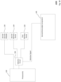
- FIG. 1A shows an example system 100A according to aspects of the disclosure.
- Processor(s) 110 of a computing device (not shown) is operatively connected to two memory devices, shown as a first memory device 122 and a second memory device 124.
- the processor(s) 110 can be any conventional processors, such as a commercially available central processing unit ("CPU").
- the processor(s) can be an embedded controller of a computing device, such as a Platform Controller Hub (“PCH,” which is a set of chips that controls data paths and support functions used in conjunction with a CPU, including for example clocking, media interfaces, I/O functions, etc.), a System on a Chip (“SOC”), etc.
- PCH Platform Controller Hub
- SOC System on a Chip
- the processor(s) 110 can be dedicated components such as an application specific integrated circuit ("ASIC") or other hardware-based processor.
- ASIC application specific integrated circuit
- the computing device may further include specialized hardware components to perform specific computing processes, such as decoding video, matching video frames with images, distorting videos, encoding distorted videos, etc.
- the processor(s) are configured to boot a plurality of operating systems.
- the first memory device 122 and the second memory device 124 are configured to store information accessible by the processor(s) 110, including instructions that can be executed by the processor(s) 110.
- the first memory device 122 and the second memory device 124 can also include data that can be retrieved, manipulated or stored by the processor(s) 110.
- the first memory device 122 and the second memory device 124 can be of any non-transitory type capable of storing information accessible by the processor(s) 110, such as a hard-drive, memory card, ROM, RAM, DVD, CD-ROM, flash memory device, write-capable, and read-only memories.
- any of a number of interfaces may be used, for example, Serial Peripheral Interfaces ("SPIs"), Low Pin Count (“LPC”), Multiplexed Address-Data (“MuxedAD”), etc.
- SPIs Serial Peripheral Interfaces
- LPC Low Pin Count
- MuxedAD Multiplexed Address-Data
- the instructions can be any set of instructions to be executed directly, such as machine code, or indirectly, such as scripts, by the processor(s) 110.
- the terms "instructions,” “application,” “steps,” and “programs” can be used interchangeably herein.
- the instructions can be stored in object code format for direct processing by a processor, or in any other computing device language including scripts or collections of independent source code modules that are interpreted on demand or compiled in advance. Functions, methods, and routines of the instructions are explained in more detail below.
- Data may be retrieved, stored or modified by the processor(s) 110 in accordance with the instructions.
- the data can be stored in computer registers, in a relational database as a table having many different fields and records, or XML documents.
- the data can also be formatted in any computing device-readable format such as, but not limited to, binary values, ASCII or Unicode.
- the data can comprise any information sufficient to identify the relevant information, such as numbers, descriptive text, proprietary codes, pointers, references to data stored in other memories such as at other network locations, or information that is used by a function to calculate the relevant data.
- the first memory device 122 and the second memory device 124 may each store a different firmware element.
- the firmware element stored by each memory device may be any type of firmware, such as coreboot (lightweight firmware that performs hardware initialization and executes additional boot logic called payloads), Universal Extensible Firmware Interface (“UEFI"), Basic Input/Output System (“BIOS”), Real Time Operating System (“RTOS”), etc.
- the first memory device 122 may store a first firmware element for booting a first operating system, for example coreboot for booting the first operating system
- the second memory device 124 may store a second firmware element for booting a second operating system, for example UEFI for booting the second operating system. Because the first memory device 122 and the second memory device 124 are separately connected to the processor(s) 110 as shown, two separate boot paths-each using a different firmware element-are created for the processor(s) 110.
- the processor(s) 110 are operatively connected to different security modules, such as a first security module 132 and a second security module 134.
- the first security module 132 and the second security module 134 may be any type of security modules, for example, Trusted Platform Modules ("TPMs"), smartcards, security chips, etc.
- TPMs Trusted Platform Modules
- Certain types of security modules, for example TPMs are designed to ensure that a particular operating system can safely run on specific hardware, such as processor(s) 110.
- the first security module 132 provides authentication for booting the first operating system that the first firmware element stored on the first memory device 122 is configured to boot
- the second security module 134 provides authentication for booting the second operating system that the second firmware element stored on the second memory device 124 is configured to boot.
- the first security module 132 is mounted on a first removable component 140.
- the first removable component 140 is removably and operatively connected to the processor(s) 110.
- the first removable component 140 may be a peripheral component, such as a keyboard module, a hard drive, a graphics card, a monitor, etc.
- the first removable component 140 may be a circuit board that is separate from one or more other circuit boards on which the processor(s) 110, the first memory device 122, the second memory device 124, and the second security module 134 are mounted.
- the first removable component 140 may have one or more features identifiable with a particular operating system. This way, during manufacturing of a computing device, a technician may place a security module corresponding to the operating system intended for the computing device simply by identifying that the first removable component 140 corresponds to the intended operating system.
- the first removable component 140 has at least one feature identifiable with the first operating system that the first firmware element stored on the first memory device 122 is configured to boot.
- the identifiable feature may be a logo, a color scheme, a keyboard arrangement, etc.
- the example system 100A may be configured such that, when the first security module 132 is operatively connected to the processor(s) 110, the processor(s) 110 are configured to select either the first operating system or the second operating system to boot in response to a selection signal.
- a selector circuit 150 as shown is operatively connected to the processor(s) 110, the first memory device 122, and the second memory device 124.
- the selector circuit 150 may include any of a number of circuit elements, for example, multiplexers, switches, logic gates, etc.
- the selector circuit 150 is configured to select one of the boot paths provided by the first memory device 122 and the second memory device 124 based on a selection signal.
- the selector circuit 150 may be configured such that, when the first removable component 140 is operatively connected to provide the selection signal to the selector circuit 150 (indicating that the first security module 132 is operatively connected to the processor(s) 110), this causes the selector circuit 150 to operatively connect the first memory device 122 to the processor(s) 110.
- the boot path provided by the first memory device 122 may be selected by the technician merely by operatively connecting the first removable component 140, which has features identifiable with the first operating system, to the selector circuit 150.
- the selector circuit 150 may be further configured such that, when the first removable component 140 is not operatively connected to provide the selection signal to the selector circuit 150 (indicating that the first security module 132 is not operatively connected to the processor(s) 110), this causes the selector circuit 150 to operatively connect the second memory device 124 to the processor(s) 110. This ensures that the processor(s) 110 does not run the first operating system when the first security module 132 is not operatively connected to the processor(s) 110.
- the processor(s) 110, the first memory device 122, the second memory device 124, second security module 134, and the selector circuit 150 may be mounted on the same circuit board, or mounted on different circuit boards.
- a vendor who manufactures hardware specifically designed for the second operating system may manufacture a motherboard that includes the processor(s) 110, the first memory device 122, the second memory device 124, the second security module 134, and the selector circuit 150.
- the processor(s) 110 on the motherboard is provided with two boot paths stored separately on the first memory device 122 and the second memory device 124.
- the vendor may only be able to provide the second security module 134 on the motherboard because it does not manufacture specific hardware for other operating systems, such as the first operating system.
- FIG. 1B shows an example system 100B according to further aspects of the disclosure.
- Example system 100B includes many of the features of example system 100A, but with certain differences as discussed further below.
- a second removable component 142 is removably and operatively connected to the processor(s) 110.
- the second removable component 142 in this example has one or more features identifiable with the second operating system that the second firmware element stored on the second memory device 124 is configured to boot.
- the identifiable feature may be a logo, a color scheme, a keyboard arrangement, etc.
- the selector circuit 150 is configured such that, when the second removable component 142 is operatively connected to provide the selection signal to the selector circuit 150, this causes the selector circuit 150 to operatively connect the second memory device 124 to the processor(s) 110.
- the second removable component 142 of example system 100B does not have any security module mounted thereon.
- the processor(s) 110, the first memory device 122, the second memory device 124, second security module 134, and the selector circuit 150 may be mounted on the same circuit board, or mounted on different circuit boards. Similar to the example in FIG. 1A , a vendor that manufactures hardware specifically designed for the second operating system may manufacture a motherboard that includes the processor(s) 110, the first memory device 122, the second memory device 124, the second security module 134, and the selector circuit 150. In the example system 100B, the intended operating system is the second operating system, so the vendor simply connects the second removable component 142, which has features identifiable with the second operating system, to the selector circuit 150. Because the motherboard manufactured by the vendor already includes the second security module 134 for authenticating the second operating system, there is no need to include another security module in the second removable component 142.
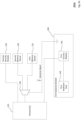
- FIGS. 2A and 2B show example systems 200A and 200B according to aspects of the disclosure.
- Example systems 200A and 200B include many of the features of example systems 100A and 100B, but with differences as discussed further below.
- the first security module 132 is mounted on a first keyboard module 144.
- the first keyboard module 144 is removably and operatively connected to the processor(s) 110.
- the first keyboard module 144 in this example has features identifiable with the first operating system that the first firmware element stored on the first memory device 122 is designed to boot.
- the first keyboard module 144 may have an arrangement or layout designed for a first type of computing device provided by a first manufacturer, which is different than the arrangement/layout designed for a another type of computing device provided by a second manufacturer.
- the arrangement/layout may be reflected by a first keyboard scan element 145, which is operatively connected to the first security module 132.
- a 2-1 multiplexer 152 is operatively connected to the processor(s) 110, the first memory device 122, and the second memory device 124.
- the 2-1 multiplexer 152 is configured such that, when the first keyboard module 144 is operatively connected to the 2-1 multiplexer 152, it provides a logic value of "0" (or "1") as a selection signal for the 2-1 multiplexer 152 and causes the 2-1 multiplexer 152 to operatively connect the first memory device 122 to the processor(s) 110.
- a second keyboard module 146 is removably and operatively connected to the processor(s) 110 instead of the first keyboard module 144.
- the second keyboard module 146 in this example has features identifiable with the second operating system that the second firmware element stored on the second memory device 124 is designed to boot.
- the second keyboard module 146 may have an arrangement/layout designed for a selected type of computing device. The arrangement/layout may be reflected by a second keyboard scan element 147, which is operatively connected to the processor(s) 110. In this scenario, the second keyboard module 146 is not provided with a connection to provide the selection signal to the 2-1 multiplexer 152.
- a resistor or other selector element 153 is operatively connected to the 2-1 multiplexer 152.
- the selector element 153 may provide a logic value of "1" (or "0") as a selection signal that causes the 2-1 multiplexer 152 to operatively connect the second memory device 124 to the processor(s) 110.
- the second keyboard module 146 of example system 200B does not have a security module mounted thereon.
- the processor(s) 110, the first memory device 122, the second memory device 124, the second security module 134, and the 2-1 multiplexer 152 may be mounted on the same circuit board, or mounted on different circuit boards.
- Example systems 200A and 200B are configured to allow an intended operating system to be easily chosen, and provided with the corresponding safety guarantee.
- the vendor that manufactures hardware specifically designed for the second operating system may manufacture a motherboard that includes the processor(s) 110, the first memory device 122, the second memory device 124, the second security module 134, and the 2-1 multiplexer 152.
- the technician may identify that the first keyboard module 144 has features identifiable with the first operating system, and operatively connect the first keyboard module 144 to the 2-1 multiplexer 152. If the intended operating system for the computing device is the second operating system, the technician may identify that the second keyboard module 146 has features identifiable with the second operating system, and not connect the second keyboard module 146 to the 2-1 multiplexer 152. Either way, the resulting computing device will have the processor(s) 110 running the intended operating system with the corresponding security module.
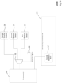
- FIG. 3 shows an example system 300 according to aspects of the disclosure.
- Example system 300 includes many of the features of example system 100A but with differences as discussed further below.
- the processor(s) 110 is operatively connected to the first memory device 122 and the second memory device 124, as well as the first security module 132 and the second security module 134.
- the example system 300 may be configured such that, when the first security module 132 is operatively connected to the processor(s) 110, the processor(s) 110 are configured to select either the first operating system or the second operating system to boot in response to a selection signal.
- a selector circuit 154 is operatively connected to the processor(s) 110, the first memory device 122, the second memory device 124, and the first security module 132.
- the selector circuit 154 is configured to select one of the boot paths provided by the first memory device 122 and the second memory device 124 based on a selection signal.
- the selection signal may be part of a signal that comes from an element such as a switch, a jumper, or another chip to choose between the different boot paths during manufacturing, installation or operation of the computing device.
- the selection signal may be part of a signal that comes from a technician or a user.
- the selector circuit 154 may be configured such that, when the selection signal causes the first memory device 122 to be chosen for providing the boot path for processor(s) 110, the selector circuit 154 enables the first security module 132. Enabling the first security module 132 may include, for example, turning power on so that the first security module 132 may provide authentication for booting the first operating system using the first firmware element stored on the first memory device 122. On the other hand, when the selection signal causes the second memory device 124 to be chosen for providing the boot path for processor(s) 110, the selector circuit 154 may be configured to disable the first security module 132.
- Disabling the first security module 132 may include, for example turning power off to that device so that the second security module 134 may provide authentication for booting the second operating system using the second firmware element stored on the second memory device 124.
- the selector circuit 154 may be operatively connected to the second security module 134, and may also be configured to enable or disable the second security module 134 based on the selection signal.
- a corresponding security module may be automatically selected. While only two security modules are shown, this approach is extendable to three or more security modules to enable booting of various different operating systems.
- the processor(s) 110, the first memory device 122, the second memory device 124, first security module 132, second security module 134, and the selector circuit 154 may all be mounted on the same circuit board. This way, a technician during manufacturing or installation may simply change the selection signal of the selector circuit 154 to select the boot path for the intended operating system, and as a result of this selection, the security module corresponding to the intended operating system would also be selected.
- FIG. 4 shows example system 400 according to aspects of the disclosure.
- Example system 400 includes many of the features of example system 100A but with differences as discussed further below.
- the processor(s) 110 is operatively connected to the first memory device 122, the second memory device 124, and selector circuit 156.
- a security module 130 is operatively connected to the processor(s) 110 and the selector circuit 156.
- the selector circuit 156 is configured such that it selects the boot path based on the operating system that the security module 130 is configured to authenticate. For example, if the security module 130 operatively connected to the selector circuit 156 is configured to provide authentication for booting an operating system stored in the first memory device 122, then connecting the security module 130 provides a selection signal that causes the selector circuit 156 to operatively connect the first memory device 122 to the processor(s) 110. This process selects the first operating system to be booted by the first firmware element stored on the first memory device 122.
- the security module 130 operatively connected to the selector circuit 156 is configured to provide authentication for booting an operating system stored in the second memory device 124
- connecting the security module 130 provides a selection signal that causes the selector circuit 156 to operatively connect the second memory device 124 to the processor(s) 110. This process selects the second operating system to be booted by the second firmware element stored on the second memory device 124.
- the processor(s) 110, the first memory device 122, the second memory device 124, the selector circuit 156, and the security module 132 may all be mounted on the same circuit board. This way, a technician during manufacturing or installation may simply connect the security module for the intended operating system to the selector circuit 156 and the processor(s) 110, and as a result of this connection, the corresponding boot path for the intended operating system would be selected. This also ensures that only the operating system having the corresponding security module is booted on the processor(s) 110.
- FIG. 5 shows an example system 500 according to aspects of the disclosure.
- FIG. 5 illustrates one example of how the features of example system 100A may be extended to more than two memory devices.
- the processor(s) 110 of example system 500 is operatively connected to a number of memory devices, such as the first memory device 122, the second memory device 124, up to an N th memory device 128, where N is a total number of memory devices in the example system 500.
- the N th memory device 128 may store an N th firmware element for booting an N th operating system.
- the processor(s) 110 can be operatively connected to the second security module 134 and an N th security module 138.
- the N th security module 138 may provide authentication for booting the N th operating system.
- the N th security module 138 is mounted on an N th removable component 148.
- the N th removable component may have features identifiable with the N th operating system.
- the example system 500 may be configured such that, when the N th security module 138 is operatively connected to the processor(s) 110, the processor(s) 110 is configured to select, in response to a selection signal, any of the operating systems that any of the firmware elements stored on any of the memory devices (including the first memory device 122, the second memory device 124, up to the N th memory device 128) is configured to boot.
- a selector circuit 158 is operatively connected to the processor(s) 110 and each of the memory devices (including the first memory device 122, the second memory device 124, up to the N th memory device 128).
- the selector circuit 158 is configured to select one of the boot paths provided by the memory devices based on a selection signal.
- the selector circuit 158 may be configured such that, when the N th removable component 148 is operatively connected to provide the selection signal to the selector circuit 158 (indicating that the N th security module 138 is operatively connected to the processor(s) 110), this causes the selector circuit 158 to operatively connect the N th memory device 128 to the processor(s) 110. This way, during manufacturing, the boot path provided by any of the memory devices may be selected by the technician merely by connecting the removable component corresponding to the intended operating system to the selector circuit 158.
- the selector circuit 158 may be further configured such that, when the N th removable component 148 is not operatively connected to provide the selection signal to the selector circuit 158 (indicating that the N th security module 138 is not operatively connected to the processor(s) 110), this causes the selector circuit 158 to operatively connect another memory device to the processor(s) 110.
- the selector circuit 158 may be configured to operatively connect to the processor(s) 110 the memory device that that has a corresponding security module operatively connected to the processor(s) 110, in this case it would be the second memory device 124 (corresponding second security module 134 is operatively connected to the processor(s) 110). This ensures that the processor(s) 110 does not run the N th operating system when the N th security module 138 is not operatively connected to the processor(s) 110.
- FIG. 5 illustrates extending the features of example system 100A to more than two memory devices
- the features of any of the example systems 100B-400B may be similarly extended.
- an N-1 multiplexer may be used for extending example systems 200A and 200B to having more than two memory devices.
- more than two memory devices and more than two security modules may be included in example system 300, and the selector circuit 154 may be modified to choose any of the memory devices and enable/disable one or more of the security modules based on a selection signal.
- more than two memory devices may be included in example system 400, and the selector circuit 156 may be modified to choose any of the memory devices based on a selection signal.
- each of the foregoing examples may be extended without having more than two memory devices, since a given firmware element may be able to boot more than one operating systems.
- the first operating system may be booted using the first firmware element stored on the first memory device 122
- the second operating system and a third operating system may be booted using the second firmware element stored on the second memory device 124
- the processor(s) 110 is configured to select the operating system to boot in response to a selection signal.
- FIG. 6 provides an example flow diagram 600 for operating a system having multiple boot paths.
- example systems 100A, 100B, 200A, 200B, 300, 400, and 500 may be operated according to the example flow diagram 600.
- block 610 it is determined whether multiple firmware elements are provided in a computing system for booting different operating systems on the computing system. For example, referring to FIGS. 1A , 1B , 2A , 2B , 3 , and 4 , it may be determined that the example system has multiple firmware elements, such as those stored in a first memory device 122 for booting a first operating system and a second memory device 124 for booting a second operating system. For another example, referring to FIG. 5 , it may be determined that the example system 500 has multiple firmware elements stored in the first memory device 122, the second memory device 124, up to the N th memory device 128 for booting different operating systems.
- a particular security module is detected to be available in the computing system. For example, referring to FIGS. 1A , 2A , and 3 , it may be determined that the example system has both the first security module 132 available for authenticating the first operating system and the second security module 134 available for authenticating the second operating system. For another example, referring to FIGS. 1B and 2B , it may be determined that the example system only has the second security module 134 available. For instance, the detection may be made based on a selection signal, which may be received from, for example, a first removable component 140 in FIG. 1A , a circuit element 153 in FIG. 2B , or a security module 130 in FIG. 4 .
- one of the firmware elements is selected for booting one of the different operating systems in response to the detection of the particular security module.
- the first memory device 122 may be selected in response to the detection of the first security module 132.
- either the first memory device 122 or the second memory device 124 may be selected based on a detection of which operating system the security module 130 is configured to authenticate.
- the N th memory device 128 may be selected in response to the detection of the N th security module 138.
Landscapes
- Engineering & Computer Science (AREA)
- Software Systems (AREA)
- Theoretical Computer Science (AREA)
- Computer Security & Cryptography (AREA)
- General Engineering & Computer Science (AREA)
- Physics & Mathematics (AREA)
- General Physics & Mathematics (AREA)
- Computer Hardware Design (AREA)
- Stored Programmes (AREA)
Description
- Firmware is software that provides instructions to a computing device's specific hardware, such as instructions to boot an operating system. A computing device may be configured to boot multiple operating systems. For example, a conventional computing device may have one firmware element configured to boot multiple operating systems. Or, alternatively, the computing device may have one firmware element that runs another firmware element as a payload. However, in such cases, there is no guarantee that all features of each operating system are fully supported. Further, the computing device may not be equipped with the necessary security authentication for each of the operating systems.
-
US 2015/0347152 A1 describes a system and method for selecting a boot configuration that utilizes a processor, a near field communication (NFC) module coupled to the processor, and a near field communication (NFC) tag proximately located to the NFC module. The NFC tag operates as a system configuration tag to configure boot mode of the processor. -
US 2010/0169949 A1 describes a system and method involving protecting a platform using locality-based data and, more specifically, using the locality-based data to ensure that the platform has not been stolen or subject to unauthorized access. In some embodiments, a second level of security, such as a key fob, badge or other source device having an identifying RFID is used for added security. - "UEFI Secure Boot in Windows 8.1", Sushovon Sinha, discloses a UEFI implemented security system called "secure boot" which secures firmware components in the computer boot process with a digital signature that the platform validates with a trusted key.
-
US 8,510,543 B1 discloses technologies for a basic input/output system (BIOS) firmware that can take different boot paths depending on the operating system that a user selects to boot within a computer system. -
US 2017/0147455A1 discloses an information processing device that includes at least a first storage device and a second storage device each to store a boot program, a first processor to read the boot program from the first storage device to boot the information processing device from the first storage device, and a second processor connected to each of the first storage device and the second storage device and the first processor. - The matter for protection is defined by the claims.
- The present disclosure provides for a computing system comprising a first memory device operatively connected to the one or more processors, the first memory device storing a first firmware element for booting a first operating system; a second memory device operatively connected to the one or more processors, the second memory device storing a second firmware element for booting a second operating system; a first security module configured to provide authentication for booting the first operating system; and a second security module operatively connected to the one or more processors, the second security module configured to provide authentication for booting the second operating system; wherein when the first security module is operatively connected to the one or more processors, the one or more processors are configured to select either the first operating system or the second operating system to boot in response to a selection signal, and when the first security module is not operatively connected to the one or more processors, the one or more processors are configured to boot the second operating system.
- The computing system may further comprise a selector circuit operatively connected to the one or more processors, the first memory device, and the second memory device, wherein the selector circuit is configured to operatively connect one of the first memory device or the second memory device to the one or more processors based on the selection signal. The selection signal may be based on whether the first security module is operatively connected to the one or more processors. The selector circuit may be configured to enable or disable the first security module based on the selection signal.
- The computing system may further comprise a removable peripheral component removably connected to the one or more processors, wherein the first security module is mounted in the removable peripheral component. The removable peripheral component may include one or more features identifiable with the first operating system. The removable peripheral component may be a keyboard module. The keyboard module may include one or more features identifiable with the first operating system. The one or more identifiable features may include a layout of keys on the keyboard module. The removable peripheral component may be a circuit board. The computing system may further comprise a selector circuit operatively connected to the one or more processors, the first memory device, the second memory device, and the removable peripheral component, wherein the selector circuit is configured to operatively connect the first memory device to the one or more processors when the removable peripheral component is operatively connected to the selector circuit.
- The one or more processors may comprise at least one of a central processing unit or an embedded controller.
- At least one of the first memory device or the second memory device may be a serial peripheral interface (SPI).
- One of the first firmware element or the second firmware element may be one of a coreboot firmware element, a Universal Extensible Firmware Interface (UEFI), or a Basic Input/Output System (BIOS).
- At least one of the first security module or the second security module may be a Trusted Platform Module (TPM).
- The disclosure further provides for a computing system comprising one or more processors; a first memory device operatively connected to the one or more processors, the first memory device storing a first firmware element for booting a first operating system; a second memory device operatively connected to the one or more processors, the second memory device storing a second firmware element for booting a second operating system; and one of either a first security module configured to provide authentication for booting the first operating system, or a second security module configured to provide authentication for booting the second operating system; wherein the one or more processors are configured to select either the first operating system or the second operating system to boot in response to whether the first security module or the second security module is operatively connected to the one or more processor.
- The computing system may further comprise a selector circuit operatively connected to the one or more processors, the first memory device, and the second memory device, wherein the selector circuit is configured to operatively connect either the first memory device or the second memory to the one or more processors based on whether the first security module or the second security module is operatively connected to the one or more processor. The selection signal may be part of a signal received from one of a switch, a jumper, or another chip. The selection signal may be part of a signal received from a user.
- The disclosure further provides for determining whether multiple firmware elements are provided in a computing system for booting different operating systems on the computing system, detecting whether a particular security module is available in the computing system, and selecting, in response to the detection of the particular security module, one of the firmware elements for booting one of the different operating systems.
-
-
FIG. 1A illustrates an example system in accordance with aspects of the disclosure. -
FIG. 1B illustrates an example system in accordance with aspects of the disclosure. -
FIG. 2A illustrates an example system in accordance with aspects of the disclosure. -
FIG. 2B illustrates an example system in accordance with aspects of the disclosure. -
FIG. 3 illustrates an example system in accordance with aspects of the disclosure. -
FIG. 4 illustrates an example system in accordance with aspects of the disclosure. -
FIG. 5 illustrates an example system in accordance with aspects of the disclosure. -
FIG. 6 is an example flow diagram illustrating an example method in accordance with aspects of the disclosure. - The technology generally relates to a system that uses multiple firmware elements to securely boot different operating systems on the same hardware platform, such as a laptop, tablet computer, wearable device such as a smartwatch or other client device. In this regard, the system includes one or more processors configured to boot the operating systems. A first memory device and a second memory device are connected to the processor(s). The memory devices may be configured to provide separate boot paths. For example, the first memory device may store a first firmware element for booting a first operating system, while the second memory device may store a second firmware element for booting a second operating system. To provide secure booting of each operating system, one or more security modules may be connected to the processor(s). For example, a first security module may be configured to provide authentication for booting the first operating system, while a second security module may be configured to provide authentication for booting the second operating system.
- The system may be configured to select an intended operating system based on a number of factors. For example, the system may be configured such that, when the first security module is connected to the processor(s), either the first operating system or the second operating system is selected in response to a selection signal, but when the first security module is not connected to the processor(s), the second operating system is selected. This way, it is ensured that the system does not boot the first operating system when the first security module is not available to provide authentication.
- For another example, the system may be configured such that, when both the first and the second security modules are available to provide authentication, one of the operating systems is selected based on a selection signal. The security modules are then selectively enabled and/or disabled based on that selection signal. This way, the system may be easily set and reset to either boot path.
- For yet another example, the system may be configured such that, when only one of the first and second security modules is available to provide authentication, the system selects the operating system that the available security module can authenticate. This way, it is ensured that the system boots the operating system that is able to be authenticated.
- For easy and secure assembly during manufacturing of the system, a given security module may be mounted on a removable component of the system. The removable component may have features readily identifiable with an intended operating system. By identifying these features, a technician may easily mount a security module that can authenticate the intended operating system on the removable component. Further, during manufacturing and assembly, the technician may easily set the intended operating system by connecting the removable component having the features identifiable with the intended operating system.
- In summary, the technical problem is that booting different operating systems on a specific hardware platform may present security issues. The technology disclosed herein provides various solutions that enable boot paths to be securely selected based on the security module(s) available to authenticate the operating system. Thus, the technology is advantageous because it provides a secure way to boot multiple operating systems on one hardware platform. By removably connecting a security module or selectively enabling a security module based on selection signals, the technology ensures secure booting of an intended operating system. Further, mounting the security module to a removable component enables easy and secure assembly during manufacturing of the hardware platform.
-
FIG. 1A shows anexample system 100A according to aspects of the disclosure. Processor(s) 110 of a computing device (not shown) is operatively connected to two memory devices, shown as afirst memory device 122 and asecond memory device 124. The processor(s) 110 can be any conventional processors, such as a commercially available central processing unit ("CPU"). Alternatively, the processor(s) can be an embedded controller of a computing device, such as a Platform Controller Hub ("PCH," which is a set of chips that controls data paths and support functions used in conjunction with a CPU, including for example clocking, media interfaces, I/O functions, etc.), a System on a Chip ("SOC"), etc. As other alternatives, the processor(s) 110 can be dedicated components such as an application specific integrated circuit ("ASIC") or other hardware-based processor. Although not necessary, the computing device (not shown) may further include specialized hardware components to perform specific computing processes, such as decoding video, matching video frames with images, distorting videos, encoding distorted videos, etc. The processor(s) are configured to boot a plurality of operating systems. - The
first memory device 122 and thesecond memory device 124 are configured to store information accessible by the processor(s) 110, including instructions that can be executed by the processor(s) 110. Thefirst memory device 122 and thesecond memory device 124 can also include data that can be retrieved, manipulated or stored by the processor(s) 110. Thefirst memory device 122 and thesecond memory device 124 can be of any non-transitory type capable of storing information accessible by the processor(s) 110, such as a hard-drive, memory card, ROM, RAM, DVD, CD-ROM, flash memory device, write-capable, and read-only memories. By way of example, for flash memory devices any of a number of interfaces may be used, for example, Serial Peripheral Interfaces ("SPIs"), Low Pin Count ("LPC"), Multiplexed Address-Data ("MuxedAD"), etc. - The instructions can be any set of instructions to be executed directly, such as machine code, or indirectly, such as scripts, by the processor(s) 110. In that regard, the terms "instructions," "application," "steps," and "programs" can be used interchangeably herein. The instructions can be stored in object code format for direct processing by a processor, or in any other computing device language including scripts or collections of independent source code modules that are interpreted on demand or compiled in advance. Functions, methods, and routines of the instructions are explained in more detail below.
- Data may be retrieved, stored or modified by the processor(s) 110 in accordance with the instructions. For instance, although the subject matter described herein is not limited by any particular data structure, the data can be stored in computer registers, in a relational database as a table having many different fields and records, or XML documents. The data can also be formatted in any computing device-readable format such as, but not limited to, binary values, ASCII or Unicode. Moreover, the data can comprise any information sufficient to identify the relevant information, such as numbers, descriptive text, proprietary codes, pointers, references to data stored in other memories such as at other network locations, or information that is used by a function to calculate the relevant data.
- The
first memory device 122 and thesecond memory device 124 may each store a different firmware element. The firmware element stored by each memory device may be any type of firmware, such as coreboot (lightweight firmware that performs hardware initialization and executes additional boot logic called payloads), Universal Extensible Firmware Interface ("UEFI"), Basic Input/Output System ("BIOS"), Real Time Operating System ("RTOS"), etc. For instance, thefirst memory device 122 may store a first firmware element for booting a first operating system, for example coreboot for booting the first operating system, while thesecond memory device 124 may store a second firmware element for booting a second operating system, for example UEFI for booting the second operating system. Because thefirst memory device 122 and thesecond memory device 124 are separately connected to the processor(s) 110 as shown, two separate boot paths-each using a different firmware element-are created for the processor(s) 110. - The processor(s) 110 are operatively connected to different security modules, such as a
first security module 132 and asecond security module 134. Thefirst security module 132 and thesecond security module 134 may be any type of security modules, for example, Trusted Platform Modules ("TPMs"), smartcards, security chips, etc. Certain types of security modules, for example TPMs, are designed to ensure that a particular operating system can safely run on specific hardware, such as processor(s) 110. In this example, thefirst security module 132 provides authentication for booting the first operating system that the first firmware element stored on thefirst memory device 122 is configured to boot, while thesecond security module 134 provides authentication for booting the second operating system that the second firmware element stored on thesecond memory device 124 is configured to boot. - In this scenario, the
first security module 132 is mounted on a firstremovable component 140. The firstremovable component 140 is removably and operatively connected to the processor(s) 110. The firstremovable component 140 may be a peripheral component, such as a keyboard module, a hard drive, a graphics card, a monitor, etc. Alternatively, the firstremovable component 140 may be a circuit board that is separate from one or more other circuit boards on which the processor(s) 110, thefirst memory device 122, thesecond memory device 124, and thesecond security module 134 are mounted. - The first
removable component 140 may have one or more features identifiable with a particular operating system. This way, during manufacturing of a computing device, a technician may place a security module corresponding to the operating system intended for the computing device simply by identifying that the firstremovable component 140 corresponds to the intended operating system. In this example, the firstremovable component 140 has at least one feature identifiable with the first operating system that the first firmware element stored on thefirst memory device 122 is configured to boot. For example, the identifiable feature may be a logo, a color scheme, a keyboard arrangement, etc. - The
example system 100A may be configured such that, when thefirst security module 132 is operatively connected to the processor(s) 110, the processor(s) 110 are configured to select either the first operating system or the second operating system to boot in response to a selection signal. In this regard, aselector circuit 150 as shown is operatively connected to the processor(s) 110, thefirst memory device 122, and thesecond memory device 124. Theselector circuit 150 may include any of a number of circuit elements, for example, multiplexers, switches, logic gates, etc. Theselector circuit 150 is configured to select one of the boot paths provided by thefirst memory device 122 and thesecond memory device 124 based on a selection signal. - For example, the
selector circuit 150 may be configured such that, when the firstremovable component 140 is operatively connected to provide the selection signal to the selector circuit 150 (indicating that thefirst security module 132 is operatively connected to the processor(s) 110), this causes theselector circuit 150 to operatively connect thefirst memory device 122 to the processor(s) 110. This way, during manufacturing of a computing device, the boot path provided by thefirst memory device 122 may be selected by the technician merely by operatively connecting the firstremovable component 140, which has features identifiable with the first operating system, to theselector circuit 150. - In contrast, the
selector circuit 150 may be further configured such that, when the firstremovable component 140 is not operatively connected to provide the selection signal to the selector circuit 150 (indicating that thefirst security module 132 is not operatively connected to the processor(s) 110), this causes theselector circuit 150 to operatively connect thesecond memory device 124 to the processor(s) 110. This ensures that the processor(s) 110 does not run the first operating system when thefirst security module 132 is not operatively connected to the processor(s) 110. - The processor(s) 110, the
first memory device 122, thesecond memory device 124,second security module 134, and theselector circuit 150 may be mounted on the same circuit board, or mounted on different circuit boards. For example, a vendor who manufactures hardware specifically designed for the second operating system may manufacture a motherboard that includes the processor(s) 110, thefirst memory device 122, thesecond memory device 124, thesecond security module 134, and theselector circuit 150. Thus, the processor(s) 110 on the motherboard is provided with two boot paths stored separately on thefirst memory device 122 and thesecond memory device 124. Here, the vendor may only be able to provide thesecond security module 134 on the motherboard because it does not manufacture specific hardware for other operating systems, such as the first operating system. However, another vendor that manufactures hardware specifically designed for the first operating system may take this motherboard and connect the firstremovable component 140 that includes thefirst security module 132 to this motherboard. This way, hardware specifically manufactured by the vendor to safely run one operating system is easily customized by the other vendor to safely run another operating system. A technician may perform this customization simply by connecting the removable component having the identifiable features corresponding to the intended operating system. -
FIG. 1B shows an example system 100B according to further aspects of the disclosure. Example system 100B includes many of the features ofexample system 100A, but with certain differences as discussed further below. InFIG. 1B , a secondremovable component 142 is removably and operatively connected to the processor(s) 110. The secondremovable component 142 in this example has one or more features identifiable with the second operating system that the second firmware element stored on thesecond memory device 124 is configured to boot. For example, the identifiable feature may be a logo, a color scheme, a keyboard arrangement, etc. In this example, theselector circuit 150 is configured such that, when the secondremovable component 142 is operatively connected to provide the selection signal to theselector circuit 150, this causes theselector circuit 150 to operatively connect thesecond memory device 124 to the processor(s) 110. In contrast to theexample system 100A ofFIG. 1A , the secondremovable component 142 of example system 100B does not have any security module mounted thereon. - Likewise for the example system 100B, the processor(s) 110, the
first memory device 122, thesecond memory device 124,second security module 134, and theselector circuit 150 may be mounted on the same circuit board, or mounted on different circuit boards. Similar to the example inFIG. 1A , a vendor that manufactures hardware specifically designed for the second operating system may manufacture a motherboard that includes the processor(s) 110, thefirst memory device 122, thesecond memory device 124, thesecond security module 134, and theselector circuit 150. In the example system 100B, the intended operating system is the second operating system, so the vendor simply connects the secondremovable component 142, which has features identifiable with the second operating system, to theselector circuit 150. Because the motherboard manufactured by the vendor already includes thesecond security module 134 for authenticating the second operating system, there is no need to include another security module in the secondremovable component 142. -
FIGS. 2A and2B showexample systems Example systems example systems 100A and 100B, but with differences as discussed further below. InFIG. 2A , thefirst security module 132 is mounted on afirst keyboard module 144. Thefirst keyboard module 144 is removably and operatively connected to the processor(s) 110. Thefirst keyboard module 144 in this example has features identifiable with the first operating system that the first firmware element stored on thefirst memory device 122 is designed to boot. For instance, thefirst keyboard module 144 may have an arrangement or layout designed for a first type of computing device provided by a first manufacturer, which is different than the arrangement/layout designed for a another type of computing device provided by a second manufacturer. The arrangement/layout may be reflected by a firstkeyboard scan element 145, which is operatively connected to thefirst security module 132. This way, during manufacturing of a computing device, a technician may place a security module corresponding to the operating system intended for the computing device simply by identifying that a keyboard module corresponds to the intended operating system, which may be possible by a quick glance. A 2-1multiplexer 152 is operatively connected to the processor(s) 110, thefirst memory device 122, and thesecond memory device 124. The 2-1multiplexer 152 is configured such that, when thefirst keyboard module 144 is operatively connected to the 2-1multiplexer 152, it provides a logic value of "0" (or "1") as a selection signal for the 2-1multiplexer 152 and causes the 2-1multiplexer 152 to operatively connect thefirst memory device 122 to the processor(s) 110. - Compare
FIG. 2A to theexample system 200B shown inFIG. 2B , where asecond keyboard module 146 is removably and operatively connected to the processor(s) 110 instead of thefirst keyboard module 144. Thesecond keyboard module 146 in this example has features identifiable with the second operating system that the second firmware element stored on thesecond memory device 124 is designed to boot. For example, thesecond keyboard module 146 may have an arrangement/layout designed for a selected type of computing device. The arrangement/layout may be reflected by a secondkeyboard scan element 147, which is operatively connected to the processor(s) 110. In this scenario, thesecond keyboard module 146 is not provided with a connection to provide the selection signal to the 2-1multiplexer 152. Rather, a resistor orother selector element 153 is operatively connected to the 2-1multiplexer 152. Theselector element 153 may provide a logic value of "1" (or "0") as a selection signal that causes the 2-1multiplexer 152 to operatively connect thesecond memory device 124 to the processor(s) 110. In contrast toFIG. 2A , thesecond keyboard module 146 ofexample system 200B does not have a security module mounted thereon. - Similar to
example systems 100A and 100B discussed above, inexample systems first memory device 122, thesecond memory device 124, thesecond security module 134, and the 2-1multiplexer 152 may be mounted on the same circuit board, or mounted on different circuit boards.Example systems first memory device 122, thesecond memory device 124, thesecond security module 134, and the 2-1multiplexer 152. During manufacturing, if the intended operating system for the computing device is the first operating system, the technician may identify that thefirst keyboard module 144 has features identifiable with the first operating system, and operatively connect thefirst keyboard module 144 to the 2-1multiplexer 152. If the intended operating system for the computing device is the second operating system, the technician may identify that thesecond keyboard module 146 has features identifiable with the second operating system, and not connect thesecond keyboard module 146 to the 2-1multiplexer 152. Either way, the resulting computing device will have the processor(s) 110 running the intended operating system with the corresponding security module. -
FIG. 3 shows anexample system 300 according to aspects of the disclosure.Example system 300 includes many of the features ofexample system 100A but with differences as discussed further below. Inexample system 300, the processor(s) 110 is operatively connected to thefirst memory device 122 and thesecond memory device 124, as well as thefirst security module 132 and thesecond security module 134. - The
example system 300 may be configured such that, when thefirst security module 132 is operatively connected to the processor(s) 110, the processor(s) 110 are configured to select either the first operating system or the second operating system to boot in response to a selection signal. In this regard, aselector circuit 154 is operatively connected to the processor(s) 110, thefirst memory device 122, thesecond memory device 124, and thefirst security module 132. Theselector circuit 154 is configured to select one of the boot paths provided by thefirst memory device 122 and thesecond memory device 124 based on a selection signal. For example, the selection signal may be part of a signal that comes from an element such as a switch, a jumper, or another chip to choose between the different boot paths during manufacturing, installation or operation of the computing device. For another example, the selection signal may be part of a signal that comes from a technician or a user. - Further, the
selector circuit 154 may be configured such that, when the selection signal causes thefirst memory device 122 to be chosen for providing the boot path for processor(s) 110, theselector circuit 154 enables thefirst security module 132. Enabling thefirst security module 132 may include, for example, turning power on so that thefirst security module 132 may provide authentication for booting the first operating system using the first firmware element stored on thefirst memory device 122. On the other hand, when the selection signal causes thesecond memory device 124 to be chosen for providing the boot path for processor(s) 110, theselector circuit 154 may be configured to disable thefirst security module 132. Disabling thefirst security module 132 may include, for example turning power off to that device so that thesecond security module 134 may provide authentication for booting the second operating system using the second firmware element stored on thesecond memory device 124. Alternatively or additionally (as shown), theselector circuit 154 may be operatively connected to thesecond security module 134, and may also be configured to enable or disable thesecond security module 134 based on the selection signal. Thus, based on the intended boot path, a corresponding security module may be automatically selected. While only two security modules are shown, this approach is extendable to three or more security modules to enable booting of various different operating systems. - In the
example system 300, the processor(s) 110, thefirst memory device 122, thesecond memory device 124,first security module 132,second security module 134, and theselector circuit 154 may all be mounted on the same circuit board. This way, a technician during manufacturing or installation may simply change the selection signal of theselector circuit 154 to select the boot path for the intended operating system, and as a result of this selection, the security module corresponding to the intended operating system would also be selected. -
FIG. 4 showsexample system 400 according to aspects of the disclosure.Example system 400 includes many of the features ofexample system 100A but with differences as discussed further below. Inexample system 400, the processor(s) 110 is operatively connected to thefirst memory device 122, thesecond memory device 124, andselector circuit 156. As shown, asecurity module 130 is operatively connected to the processor(s) 110 and theselector circuit 156. - The
selector circuit 156 is configured such that it selects the boot path based on the operating system that thesecurity module 130 is configured to authenticate. For example, if thesecurity module 130 operatively connected to theselector circuit 156 is configured to provide authentication for booting an operating system stored in thefirst memory device 122, then connecting thesecurity module 130 provides a selection signal that causes theselector circuit 156 to operatively connect thefirst memory device 122 to the processor(s) 110. This process selects the first operating system to be booted by the first firmware element stored on thefirst memory device 122. For another example, if thesecurity module 130 operatively connected to theselector circuit 156 is configured to provide authentication for booting an operating system stored in thesecond memory device 124, then connecting thesecurity module 130 provides a selection signal that causes theselector circuit 156 to operatively connect thesecond memory device 124 to the processor(s) 110. This process selects the second operating system to be booted by the second firmware element stored on thesecond memory device 124. - In the
example system 400, the processor(s) 110, thefirst memory device 122, thesecond memory device 124, theselector circuit 156, and thesecurity module 132 may all be mounted on the same circuit board. This way, a technician during manufacturing or installation may simply connect the security module for the intended operating system to theselector circuit 156 and the processor(s) 110, and as a result of this connection, the corresponding boot path for the intended operating system would be selected. This also ensures that only the operating system having the corresponding security module is booted on the processor(s) 110. - Although each of the foregoing examples have two memory devices that provide two separate boot paths on the same hardware system, the features described with respect to the foregoing examples may readily be extended to any number of memory devices providing any number of separate boot paths on the same hardware system.
-
FIG. 5 shows anexample system 500 according to aspects of the disclosure.FIG. 5 illustrates one example of how the features ofexample system 100A may be extended to more than two memory devices. As shown, the processor(s) 110 ofexample system 500 is operatively connected to a number of memory devices, such as thefirst memory device 122, thesecond memory device 124, up to an Nth memory device 128, where N is a total number of memory devices in theexample system 500. For example, the Nth memory device 128 may store an Nth firmware element for booting an Nth operating system. The processor(s) 110 can be operatively connected to thesecond security module 134 and an Nth security module 138. For example, the Nth security module 138 may provide authentication for booting the Nth operating system. The Nth security module 138 is mounted on an Nthremovable component 148. For example, the Nth removable component may have features identifiable with the Nth operating system. - The
example system 500 may be configured such that, when the Nth security module 138 is operatively connected to the processor(s) 110, the processor(s) 110 is configured to select, in response to a selection signal, any of the operating systems that any of the firmware elements stored on any of the memory devices (including thefirst memory device 122, thesecond memory device 124, up to the Nth memory device 128) is configured to boot. In this regard, aselector circuit 158 is operatively connected to the processor(s) 110 and each of the memory devices (including thefirst memory device 122, thesecond memory device 124, up to the Nth memory device 128). Theselector circuit 158 is configured to select one of the boot paths provided by the memory devices based on a selection signal. - For example, the
selector circuit 158 may be configured such that, when the Nthremovable component 148 is operatively connected to provide the selection signal to the selector circuit 158 (indicating that the Nth security module 138 is operatively connected to the processor(s) 110), this causes theselector circuit 158 to operatively connect the Nth memory device 128 to the processor(s) 110. This way, during manufacturing, the boot path provided by any of the memory devices may be selected by the technician merely by connecting the removable component corresponding to the intended operating system to theselector circuit 158. - For another example, the
selector circuit 158 may be further configured such that, when the Nthremovable component 148 is not operatively connected to provide the selection signal to the selector circuit 158 (indicating that the Nth security module 138 is not operatively connected to the processor(s) 110), this causes theselector circuit 158 to operatively connect another memory device to the processor(s) 110. For example, theselector circuit 158 may be configured to operatively connect to the processor(s) 110 the memory device that that has a corresponding security module operatively connected to the processor(s) 110, in this case it would be the second memory device 124 (correspondingsecond security module 134 is operatively connected to the processor(s) 110). This ensures that the processor(s) 110 does not run the Nth operating system when the Nth security module 138 is not operatively connected to the processor(s) 110. - Although
FIG. 5 illustrates extending the features ofexample system 100A to more than two memory devices, the features of any of the example systems 100B-400B may be similarly extended. For example, an N-1 multiplexer may be used for extendingexample systems example system 300, and theselector circuit 154 may be modified to choose any of the memory devices and enable/disable one or more of the security modules based on a selection signal. For yet another example, more than two memory devices may be included inexample system 400, and theselector circuit 156 may be modified to choose any of the memory devices based on a selection signal. - Still further, each of the foregoing examples may be extended without having more than two memory devices, since a given firmware element may be able to boot more than one operating systems. For example, the first operating system may be booted using the first firmware element stored on the
first memory device 122, while the second operating system and a third operating system may be booted using the second firmware element stored on thesecond memory device 124, and the processor(s) 110 is configured to select the operating system to boot in response to a selection signal. - Further to the example systems described above, an example method is now described.
-
FIG. 6 provides an example flow diagram 600 for operating a system having multiple boot paths. For example,example systems - In
block 610, it is determined whether multiple firmware elements are provided in a computing system for booting different operating systems on the computing system. For example, referring toFIGS. 1A ,1B ,2A ,2B ,3 , and4 , it may be determined that the example system has multiple firmware elements, such as those stored in afirst memory device 122 for booting a first operating system and asecond memory device 124 for booting a second operating system. For another example, referring toFIG. 5 , it may be determined that theexample system 500 has multiple firmware elements stored in thefirst memory device 122, thesecond memory device 124, up to the Nth memory device 128 for booting different operating systems. - In
block 620, a particular security module is detected to be available in the computing system. For example, referring toFIGS. 1A ,2A , and3 , it may be determined that the example system has both thefirst security module 132 available for authenticating the first operating system and thesecond security module 134 available for authenticating the second operating system. For another example, referring toFIGS. 1B and2B , it may be determined that the example system only has thesecond security module 134 available. For instance, the detection may be made based on a selection signal, which may be received from, for example, a firstremovable component 140 inFIG. 1A , acircuit element 153 inFIG. 2B , or asecurity module 130 inFIG. 4 . - In
block 630, one of the firmware elements is selected for booting one of the different operating systems in response to the detection of the particular security module. For example, referring toFIGS. 1A and2A , thefirst memory device 122 may be selected in response to the detection of thefirst security module 132. For another example, referring toFIG. 4 , either thefirst memory device 122 or thesecond memory device 124 may be selected based on a detection of which operating system thesecurity module 130 is configured to authenticate. For yet another example, referring toFIG. 5 , the Nth memory device 128 may be selected in response to the detection of the Nth security module 138. - Unless otherwise stated, the foregoing alternative examples are not mutually exclusive, but may be implemented in various combinations to achieve unique advantages. As these and other variations and combinations of the features discussed above can be utilized without departing from the subject matter defined by the claims, the foregoing description of the embodiments should be taken by way of illustration rather than by way of limitation of the subject matter defined by the claims. In addition, the provision of the examples described herein, as well as clauses phrased as "such as," "including" and the like, should not be interpreted as limiting the subject matter of the claims to the specific examples; rather, the examples are intended to illustrate only one of many possible embodiments. Further, the same reference numbers in different drawings can identify the same or similar elements.
Claims (15)
- A computing system (100A), comprising:one or more processors (110);a first memory device (122) operatively connected to the one or more processors to provide a first boot path, the first memory device storing a first firmware element for booting a first operating system;a second memory device (124) operatively connected to the one or more processors to provide a second boot path, the second memory device storing a second firmware element for booting a second operating system;a second security module (134) operatively connected to the one or more processors, the second security module configured to ensure the second operating system can safely run on the one or more processors; anda selector circuit (150) operatively connected to the one or more processors, the first memory device, and the second memory device;wherein the one or more processors are configured:to boot either the first operating system or the second operating system according to a selected boot path determined by a selection signal, when a first security module, which is configured to ensure the first operating system can safely run on the one or more processors, is operatively connected to the one or more processors, andto boot the second operating system when the first security module is not operatively connected to the one or more processors;wherein the selector circuit is configured to select one of the first and second boot paths based on the selection signal.
- The system of claim 1, wherein the selection signal is based on whether the first security module is operatively connected to the one or more processors.
- The system of claim 1, wherein the selector circuit is configured to enable or disable the first security module based on the selection signal.
- The system of any preceding claim, wherein the first security module is mounted in a removable peripheral component (140) which is removably connectable to the one or more processors.
- The system of claim 4, wherein the system includes the removable peripheral component and the removable peripheral component includes one or more features identifiable with the first operating system.
- The system of any one of claims 4, wherein the removable peripheral component is a keyboard module (144).
- The system of claim 6, wherein the system includes the keyboard module and the keyboard module includes one or more features identifiable with the first operating system, and optionally wherein the one or more identifiable features includes a layout of keys on the keyboard module.
- The system of claim 4, wherein the removable peripheral component is a circuit board.
- The system of any one of the preceding claims, wherein the one or more processors comprise at least one of a central processing unit or an embedded controller, and/or wherein at least one of the first memory device or the second memory device is a serial peripheral interface (SPI).
- The system of any one of the preceding claims, wherein one of the first firmware element or the second firmware element is one of a coreboot firmware element, a Universal Extensible Firmware Interface (UEFI), or a Basic Input/Output System (BIOS).
- The system of any one of the preceding claims, wherein at least one of the first security module or the second security module is a Trusted Platform Module (TPM).
- The system of any one of the preceding claims, further comprising the first security module.
- The system of any of claim 4, further comprising the removable peripheral component.
- A computing system, comprising:one or more processors;a first memory device operatively connected to the one or more processors to provide a first boot path, the first memory device storing a first firmware element for booting a first operating system;a second memory device operatively connected to the one or more processors to provide a second boot path, the second memory device storing a second firmware element for booting a second operating system;a selector circuit operatively connected to the one or more processors, the first memory device, and the second memory device; andone of either a first security module configured to ensure the first operating system can safely run on the one or more processors, or a second security module configured to ensure the second operating system can safely run on the one or more processors;wherein the selector circuit is configured:to select the first boot path, such that the one or more processors boot the first operating system, when the first security module is operatively connected to the one or more processors; andto select the second boot path, such that the one or more processors boot the second operating system, when the second security module is operatively connected to the one or more processors.
- A method performed by a computing system which comprises one or more processors (110), a first memory device (122) operatively connected to the one or more processors to provide a first boot path, the first memory device storing a first firmware element for booting a first operating system, a second memory device (124) operatively connected to the one or more processors to provide a second boot path, the second memory device storing a second firmware element for booting a second operating system, a second security module (134) operatively connected to the one or more processors, the second security module configured to ensure the second operating system can safely run on the one or more processors, and a selector circuit (150) operatively connected to the one or more processors, the first memory device, and the second memory device, wherein the method comprises:when a first security module, which is configured to ensure the first operating system can safely run on the one or more processors, is operatively connected to the one or more processors, booting either the first operating system or the second operating system in response to a selection signal, andwhen the first security module is not operatively connected to the one or more processors, booting the second operating system;wherein the selector circuit selects one of first boot path and the second boot path based on the selection signal.
Applications Claiming Priority (2)
| Application Number | Priority Date | Filing Date | Title |
|---|---|---|---|
| US16/004,586 US10802834B2 (en) | 2018-06-11 | 2018-06-11 | Enabling multiple secure boot paths on a hardware platform |
| PCT/US2019/035557 WO2019241003A1 (en) | 2018-06-11 | 2019-06-05 | Enabling multiple secure boot paths on a hardware platform |
Publications (2)
| Publication Number | Publication Date |
|---|---|
| EP3785115A1 EP3785115A1 (en) | 2021-03-03 |
| EP3785115B1 true EP3785115B1 (en) | 2023-09-13 |
Family
ID=67002406
Family Applications (1)
| Application Number | Title | Priority Date | Filing Date |
|---|---|---|---|
| EP19732826.3A Active EP3785115B1 (en) | 2018-06-11 | 2019-06-05 | Enabling multiple secure boot paths on a hardware platform |
Country Status (4)
| Country | Link |
|---|---|
| US (1) | US10802834B2 (en) |
| EP (1) | EP3785115B1 (en) |
| CN (1) | CN112219187B (en) |
| WO (1) | WO2019241003A1 (en) |
Families Citing this family (6)
| Publication number | Priority date | Publication date | Assignee | Title |
|---|---|---|---|---|
| US11281471B2 (en) * | 2020-02-14 | 2022-03-22 | Dell Products L.P. | Systems and methods for minimizing boot time and minimizing unauthorized access and attack surface in basic input/output system |
| WO2021194501A1 (en) * | 2020-03-27 | 2021-09-30 | Hewlett-Packard Development Company, L.P. | Alternate operating systems |
| KR20230064623A (en) * | 2020-09-08 | 2023-05-10 | 오솜 프로덕츠 인코포레이티드 | Mobile devices with secure personal memory |
| US11921858B2 (en) * | 2021-06-08 | 2024-03-05 | Dell Products L.P. | System and method for protecting against alterations in chain of trust sequences |
| CN116360865A (en) * | 2021-12-27 | 2023-06-30 | 华为技术有限公司 | Cluster management method, device and computing system |
| US20250045408A1 (en) * | 2023-08-03 | 2025-02-06 | Selective Intellect LLC | Systems and Methods for Cryptographically Verifying a User of a Computing Device at the Bootloader Level |
Family Cites Families (12)
| Publication number | Priority date | Publication date | Assignee | Title |
|---|---|---|---|---|
| EP2186251B1 (en) * | 2007-08-28 | 2019-10-09 | ABB Schweiz AG | Real-time communication security for automation networks |
| US8561138B2 (en) * | 2008-12-31 | 2013-10-15 | Intel Corporation | System and method to provide added security to a platform using locality-based data |
| US8510543B1 (en) | 2009-05-28 | 2013-08-13 | American Megatrends, Inc. | Firmware supporting multiple boot paths |
| US20110119474A1 (en) | 2009-11-16 | 2011-05-19 | Bally Gaming, Inc. | Serial Peripheral Interface BIOS System and Method |
| CN102200933A (en) | 2010-03-23 | 2011-09-28 | 深圳华北工控股份有限公司 | System BIOS (Basic Input/Output System) automatic restoring method based on dual SPI (Serial Peripheral interface) Flashes |
| US20130297924A1 (en) | 2012-04-03 | 2013-11-07 | Insyde Software | Method of running multiple operating systems on an x86-based computer |
| US9471330B2 (en) | 2014-05-30 | 2016-10-18 | Motorola Solutions, Inc. | System and method and for selecting boot configuration using near field communication |
| US9785801B2 (en) | 2014-06-27 | 2017-10-10 | Intel Corporation | Management of authenticated variables |
| CN104360867B (en) | 2014-12-01 | 2018-02-23 | 重庆蓝岸通讯技术有限公司 | A kind of switching method based on Intel X86 32-bit Windows system and 64 android systems |
| US10223217B2 (en) | 2015-11-24 | 2019-03-05 | Ricoh Company, Ltd. | Information processing device, method for booting information processing device, and non-transitory recording medium |
| CN106990958B (en) | 2017-03-17 | 2019-12-24 | 联想(北京)有限公司 | Expansion assembly, electronic equipment and starting method |
| US10467416B2 (en) * | 2017-06-16 | 2019-11-05 | International Business Machines Corporation | Securing operating system configuration using hardware |
-
2018
- 2018-06-11 US US16/004,586 patent/US10802834B2/en active Active
-
2019
- 2019-06-05 CN CN201980037554.XA patent/CN112219187B/en active Active
- 2019-06-05 WO PCT/US2019/035557 patent/WO2019241003A1/en not_active Ceased
- 2019-06-05 EP EP19732826.3A patent/EP3785115B1/en active Active
Also Published As
| Publication number | Publication date |
|---|---|
| US20190377583A1 (en) | 2019-12-12 |
| WO2019241003A1 (en) | 2019-12-19 |
| US10802834B2 (en) | 2020-10-13 |
| CN112219187B (en) | 2024-08-06 |
| EP3785115A1 (en) | 2021-03-03 |
| CN112219187A (en) | 2021-01-12 |
Similar Documents
| Publication | Publication Date | Title |
|---|---|---|
| US10802834B2 (en) | Enabling multiple secure boot paths on a hardware platform | |
| US7689817B2 (en) | Methods and apparatus for defeating malware | |
| US11194586B2 (en) | Secure boot override in a computing device equipped with unified-extensible firmware interface (UEFI)-compliant firmware | |
| US7917741B2 (en) | Enhancing security of a system via access by an embedded controller to a secure storage device | |
| US7849315B2 (en) | Method for managing operability of on-chip debug capability | |
| US8954804B2 (en) | Secure boot circuit and method | |
| US9525555B2 (en) | Partitioning access to system resources | |
| US7769993B2 (en) | Method for ensuring boot source integrity of a computing system | |
| US20020166062A1 (en) | Method and apparatus for enhancing computer system security | |
| US20090307478A1 (en) | Platform boot with bridge support | |
| US20040128260A1 (en) | Method and system for protecting against unauthorized modification of products | |
| US20040103299A1 (en) | Providing a secure execution mode in a pre-boot environment | |
| US9436828B2 (en) | Systems and methods for command-based entry into basic input/output system setup from operating system | |
| US20090177999A1 (en) | Replacement motherboard configuration | |
| US20140373183A1 (en) | Computer and control method thereof | |
| US20190171803A1 (en) | Method and apparatus for user authentication based on touch input including fingerprint information | |
| CN114417301B (en) | Information processing method, information processing device, electronic device and storage medium | |
| US9218512B2 (en) | Portable computer and operating method thereof | |
| US8151104B2 (en) | Establishing user-defined management engine default settings stored in a system memory | |
| CN102024099B (en) | A personal computer booting identification method and a system for the same | |
| KR20050123152A (en) | Physical presence determination in a trusted platform | |
| CN115687039B (en) | Cloud platform verification method, cloud platform verification component and ARM cloud platform | |
| CN117319528A (en) | Automatic identification method for vehicle-mounted display terminal panel and related equipment | |
| CN112020703A (en) | BIOS personality | |
| US6944601B2 (en) | Method of licensing software programs |
Legal Events
| Date | Code | Title | Description |
|---|---|---|---|
| STAA | Information on the status of an ep patent application or granted ep patent |
Free format text: STATUS: UNKNOWN |
|
| STAA | Information on the status of an ep patent application or granted ep patent |
Free format text: STATUS: THE INTERNATIONAL PUBLICATION HAS BEEN MADE |
|
| PUAI | Public reference made under article 153(3) epc to a published international application that has entered the european phase |
Free format text: ORIGINAL CODE: 0009012 |
|
| STAA | Information on the status of an ep patent application or granted ep patent |
Free format text: STATUS: REQUEST FOR EXAMINATION WAS MADE |
|
| 17P | Request for examination filed |
Effective date: 20201127 |
|
| AK | Designated contracting states |
Kind code of ref document: A1 Designated state(s): AL AT BE BG CH CY CZ DE DK EE ES FI FR GB GR HR HU IE IS IT LI LT LU LV MC MK MT NL NO PL PT RO RS SE SI SK SM TR |
|
| AX | Request for extension of the european patent |
Extension state: BA ME |
|
| DAV | Request for validation of the european patent (deleted) | ||
| DAX | Request for extension of the european patent (deleted) | ||
| GRAP | Despatch of communication of intention to grant a patent |
Free format text: ORIGINAL CODE: EPIDOSNIGR1 |
|
| STAA | Information on the status of an ep patent application or granted ep patent |
Free format text: STATUS: GRANT OF PATENT IS INTENDED |
|
| INTG | Intention to grant announced |
Effective date: 20230404 |
|
| P01 | Opt-out of the competence of the unified patent court (upc) registered |
Effective date: 20230527 |
|
| GRAS | Grant fee paid |
Free format text: ORIGINAL CODE: EPIDOSNIGR3 |
|
| GRAA | (expected) grant |
Free format text: ORIGINAL CODE: 0009210 |
|
| STAA | Information on the status of an ep patent application or granted ep patent |
Free format text: STATUS: THE PATENT HAS BEEN GRANTED |
|
| AK | Designated contracting states |
Kind code of ref document: B1 Designated state(s): AL AT BE BG CH CY CZ DE DK EE ES FI FR GB GR HR HU IE IS IT LI LT LU LV MC MK MT NL NO PL PT RO RS SE SI SK SM TR |
|
| REG | Reference to a national code |
Ref country code: CH Ref legal event code: EP |
|
| REG | Reference to a national code |
Ref country code: DE Ref legal event code: R096 Ref document number: 602019037347 Country of ref document: DE |
|
| REG | Reference to a national code |
Ref country code: IE Ref legal event code: FG4D |
|
| REG | Reference to a national code |
Ref country code: LT Ref legal event code: MG9D |
|
| REG | Reference to a national code |
Ref country code: NL Ref legal event code: MP Effective date: 20230913 |
|
| PG25 | Lapsed in a contracting state [announced via postgrant information from national office to epo] |
Ref country code: GR Free format text: LAPSE BECAUSE OF FAILURE TO SUBMIT A TRANSLATION OF THE DESCRIPTION OR TO PAY THE FEE WITHIN THE PRESCRIBED TIME-LIMIT Effective date: 20231214 |
|
| PG25 | Lapsed in a contracting state [announced via postgrant information from national office to epo] |
Ref country code: SE Free format text: LAPSE BECAUSE OF FAILURE TO SUBMIT A TRANSLATION OF THE DESCRIPTION OR TO PAY THE FEE WITHIN THE PRESCRIBED TIME-LIMIT Effective date: 20230913 Ref country code: RS Free format text: LAPSE BECAUSE OF FAILURE TO SUBMIT A TRANSLATION OF THE DESCRIPTION OR TO PAY THE FEE WITHIN THE PRESCRIBED TIME-LIMIT Effective date: 20230913 Ref country code: NO Free format text: LAPSE BECAUSE OF FAILURE TO SUBMIT A TRANSLATION OF THE DESCRIPTION OR TO PAY THE FEE WITHIN THE PRESCRIBED TIME-LIMIT Effective date: 20231213 Ref country code: LV Free format text: LAPSE BECAUSE OF FAILURE TO SUBMIT A TRANSLATION OF THE DESCRIPTION OR TO PAY THE FEE WITHIN THE PRESCRIBED TIME-LIMIT Effective date: 20230913 Ref country code: LT Free format text: LAPSE BECAUSE OF FAILURE TO SUBMIT A TRANSLATION OF THE DESCRIPTION OR TO PAY THE FEE WITHIN THE PRESCRIBED TIME-LIMIT Effective date: 20230913 Ref country code: HR Free format text: LAPSE BECAUSE OF FAILURE TO SUBMIT A TRANSLATION OF THE DESCRIPTION OR TO PAY THE FEE WITHIN THE PRESCRIBED TIME-LIMIT Effective date: 20230913 Ref country code: GR Free format text: LAPSE BECAUSE OF FAILURE TO SUBMIT A TRANSLATION OF THE DESCRIPTION OR TO PAY THE FEE WITHIN THE PRESCRIBED TIME-LIMIT Effective date: 20231214 Ref country code: FI Free format text: LAPSE BECAUSE OF FAILURE TO SUBMIT A TRANSLATION OF THE DESCRIPTION OR TO PAY THE FEE WITHIN THE PRESCRIBED TIME-LIMIT Effective date: 20230913 |
|
| REG | Reference to a national code |
Ref country code: AT Ref legal event code: MK05 Ref document number: 1611957 Country of ref document: AT Kind code of ref document: T Effective date: 20230913 |
|
| PG25 | Lapsed in a contracting state [announced via postgrant information from national office to epo] |
Ref country code: NL Free format text: LAPSE BECAUSE OF FAILURE TO SUBMIT A TRANSLATION OF THE DESCRIPTION OR TO PAY THE FEE WITHIN THE PRESCRIBED TIME-LIMIT Effective date: 20230913 |
|
| PG25 | Lapsed in a contracting state [announced via postgrant information from national office to epo] |
Ref country code: IS Free format text: LAPSE BECAUSE OF FAILURE TO SUBMIT A TRANSLATION OF THE DESCRIPTION OR TO PAY THE FEE WITHIN THE PRESCRIBED TIME-LIMIT Effective date: 20240113 |
|
| PG25 | Lapsed in a contracting state [announced via postgrant information from national office to epo] |
Ref country code: AT Free format text: LAPSE BECAUSE OF FAILURE TO SUBMIT A TRANSLATION OF THE DESCRIPTION OR TO PAY THE FEE WITHIN THE PRESCRIBED TIME-LIMIT Effective date: 20230913 |
|
| PG25 | Lapsed in a contracting state [announced via postgrant information from national office to epo] |
Ref country code: ES Free format text: LAPSE BECAUSE OF FAILURE TO SUBMIT A TRANSLATION OF THE DESCRIPTION OR TO PAY THE FEE WITHIN THE PRESCRIBED TIME-LIMIT Effective date: 20230913 |
|
| PG25 | Lapsed in a contracting state [announced via postgrant information from national office to epo] |
Ref country code: SM Free format text: LAPSE BECAUSE OF FAILURE TO SUBMIT A TRANSLATION OF THE DESCRIPTION OR TO PAY THE FEE WITHIN THE PRESCRIBED TIME-LIMIT Effective date: 20230913 Ref country code: RO Free format text: LAPSE BECAUSE OF FAILURE TO SUBMIT A TRANSLATION OF THE DESCRIPTION OR TO PAY THE FEE WITHIN THE PRESCRIBED TIME-LIMIT Effective date: 20230913 Ref country code: IS Free format text: LAPSE BECAUSE OF FAILURE TO SUBMIT A TRANSLATION OF THE DESCRIPTION OR TO PAY THE FEE WITHIN THE PRESCRIBED TIME-LIMIT Effective date: 20240113 Ref country code: ES Free format text: LAPSE BECAUSE OF FAILURE TO SUBMIT A TRANSLATION OF THE DESCRIPTION OR TO PAY THE FEE WITHIN THE PRESCRIBED TIME-LIMIT Effective date: 20230913 Ref country code: EE Free format text: LAPSE BECAUSE OF FAILURE TO SUBMIT A TRANSLATION OF THE DESCRIPTION OR TO PAY THE FEE WITHIN THE PRESCRIBED TIME-LIMIT Effective date: 20230913 Ref country code: CZ Free format text: LAPSE BECAUSE OF FAILURE TO SUBMIT A TRANSLATION OF THE DESCRIPTION OR TO PAY THE FEE WITHIN THE PRESCRIBED TIME-LIMIT Effective date: 20230913 Ref country code: AT Free format text: LAPSE BECAUSE OF FAILURE TO SUBMIT A TRANSLATION OF THE DESCRIPTION OR TO PAY THE FEE WITHIN THE PRESCRIBED TIME-LIMIT Effective date: 20230913 Ref country code: SK Free format text: LAPSE BECAUSE OF FAILURE TO SUBMIT A TRANSLATION OF THE DESCRIPTION OR TO PAY THE FEE WITHIN THE PRESCRIBED TIME-LIMIT Effective date: 20230913 Ref country code: PT Free format text: LAPSE BECAUSE OF FAILURE TO SUBMIT A TRANSLATION OF THE DESCRIPTION OR TO PAY THE FEE WITHIN THE PRESCRIBED TIME-LIMIT Effective date: 20240115 |
|
| PG25 | Lapsed in a contracting state [announced via postgrant information from national office to epo] |
Ref country code: PL Free format text: LAPSE BECAUSE OF FAILURE TO SUBMIT A TRANSLATION OF THE DESCRIPTION OR TO PAY THE FEE WITHIN THE PRESCRIBED TIME-LIMIT Effective date: 20230913 Ref country code: IT Free format text: LAPSE BECAUSE OF FAILURE TO SUBMIT A TRANSLATION OF THE DESCRIPTION OR TO PAY THE FEE WITHIN THE PRESCRIBED TIME-LIMIT Effective date: 20230913 |
|
| REG | Reference to a national code |
Ref country code: DE Ref legal event code: R097 Ref document number: 602019037347 Country of ref document: DE |
|
| PG25 | Lapsed in a contracting state [announced via postgrant information from national office to epo] |
Ref country code: DK Free format text: LAPSE BECAUSE OF FAILURE TO SUBMIT A TRANSLATION OF THE DESCRIPTION OR TO PAY THE FEE WITHIN THE PRESCRIBED TIME-LIMIT Effective date: 20230913 |
|
| PLBE | No opposition filed within time limit |
Free format text: ORIGINAL CODE: 0009261 |
|
| STAA | Information on the status of an ep patent application or granted ep patent |
Free format text: STATUS: NO OPPOSITION FILED WITHIN TIME LIMIT |
|
| PG25 | Lapsed in a contracting state [announced via postgrant information from national office to epo] |
Ref country code: DK Free format text: LAPSE BECAUSE OF FAILURE TO SUBMIT A TRANSLATION OF THE DESCRIPTION OR TO PAY THE FEE WITHIN THE PRESCRIBED TIME-LIMIT Effective date: 20230913 |
|
| 26N | No opposition filed |
Effective date: 20240614 |
|
| PG25 | Lapsed in a contracting state [announced via postgrant information from national office to epo] |
Ref country code: SI Free format text: LAPSE BECAUSE OF FAILURE TO SUBMIT A TRANSLATION OF THE DESCRIPTION OR TO PAY THE FEE WITHIN THE PRESCRIBED TIME-LIMIT Effective date: 20230913 |
|
| PG25 | Lapsed in a contracting state [announced via postgrant information from national office to epo] |
Ref country code: SI Free format text: LAPSE BECAUSE OF FAILURE TO SUBMIT A TRANSLATION OF THE DESCRIPTION OR TO PAY THE FEE WITHIN THE PRESCRIBED TIME-LIMIT Effective date: 20230913 |
|
| PG25 | Lapsed in a contracting state [announced via postgrant information from national office to epo] |
Ref country code: BG Free format text: LAPSE BECAUSE OF FAILURE TO SUBMIT A TRANSLATION OF THE DESCRIPTION OR TO PAY THE FEE WITHIN THE PRESCRIBED TIME-LIMIT Effective date: 20230913 |
|
| PG25 | Lapsed in a contracting state [announced via postgrant information from national office to epo] |
Ref country code: BG Free format text: LAPSE BECAUSE OF FAILURE TO SUBMIT A TRANSLATION OF THE DESCRIPTION OR TO PAY THE FEE WITHIN THE PRESCRIBED TIME-LIMIT Effective date: 20230913 |
|
| PG25 | Lapsed in a contracting state [announced via postgrant information from national office to epo] |
Ref country code: MC Free format text: LAPSE BECAUSE OF FAILURE TO SUBMIT A TRANSLATION OF THE DESCRIPTION OR TO PAY THE FEE WITHIN THE PRESCRIBED TIME-LIMIT Effective date: 20230913 |
|
| REG | Reference to a national code |
Ref country code: CH Ref legal event code: PL |
|
| PG25 | Lapsed in a contracting state [announced via postgrant information from national office to epo] |
Ref country code: LU Free format text: LAPSE BECAUSE OF NON-PAYMENT OF DUE FEES Effective date: 20240605 |
|
| PG25 | Lapsed in a contracting state [announced via postgrant information from national office to epo] |
Ref country code: IE Free format text: LAPSE BECAUSE OF NON-PAYMENT OF DUE FEES Effective date: 20240605 |
|
| PG25 | Lapsed in a contracting state [announced via postgrant information from national office to epo] |
Ref country code: BE Free format text: LAPSE BECAUSE OF NON-PAYMENT OF DUE FEES Effective date: 20240630 Ref country code: CH Free format text: LAPSE BECAUSE OF NON-PAYMENT OF DUE FEES Effective date: 20240630 |
|
| REG | Reference to a national code |
Ref country code: BE Ref legal event code: MM Effective date: 20240630 |
|
| PGFP | Annual fee paid to national office [announced via postgrant information from national office to epo] |
Ref country code: DE Payment date: 20250627 Year of fee payment: 7 |
|
| PGFP | Annual fee paid to national office [announced via postgrant information from national office to epo] |
Ref country code: GB Payment date: 20250627 Year of fee payment: 7 |
|
| PGFP | Annual fee paid to national office [announced via postgrant information from national office to epo] |
Ref country code: FR Payment date: 20250625 Year of fee payment: 7 |
|
| PG25 | Lapsed in a contracting state [announced via postgrant information from national office to epo] |
Ref country code: CY Free format text: LAPSE BECAUSE OF FAILURE TO SUBMIT A TRANSLATION OF THE DESCRIPTION OR TO PAY THE FEE WITHIN THE PRESCRIBED TIME-LIMIT; INVALID AB INITIO Effective date: 20190605 |
|
| PG25 | Lapsed in a contracting state [announced via postgrant information from national office to epo] |
Ref country code: HU Free format text: LAPSE BECAUSE OF FAILURE TO SUBMIT A TRANSLATION OF THE DESCRIPTION OR TO PAY THE FEE WITHIN THE PRESCRIBED TIME-LIMIT; INVALID AB INITIO Effective date: 20190605 |