EP3784993B1 - Coriolis-durchflussmesser mit mehreren aktuatoren - Google Patents
Coriolis-durchflussmesser mit mehreren aktuatoren Download PDFInfo
- Publication number
- EP3784993B1 EP3784993B1 EP19718698.4A EP19718698A EP3784993B1 EP 3784993 B1 EP3784993 B1 EP 3784993B1 EP 19718698 A EP19718698 A EP 19718698A EP 3784993 B1 EP3784993 B1 EP 3784993B1
- Authority
- EP
- European Patent Office
- Prior art keywords
- flow tube
- flow
- oscillation
- coriolis
- actuator
- Prior art date
- Legal status (The legal status is an assumption and is not a legal conclusion. Google has not performed a legal analysis and makes no representation as to the accuracy of the status listed.)
- Active
Links
Images




Classifications
-
- G—PHYSICS
- G01—MEASURING; TESTING
- G01F—MEASURING VOLUME, VOLUME FLOW, MASS FLOW OR LIQUID LEVEL; METERING BY VOLUME
- G01F1/00—Measuring the volume flow or mass flow of fluid or fluent solid material wherein the fluid passes through a meter in a continuous flow
- G01F1/76—Devices for measuring mass flow of a fluid or a fluent solid material
- G01F1/78—Direct mass flowmeters
- G01F1/80—Direct mass flowmeters operating by measuring pressure, force, momentum, or frequency of a fluid flow to which a rotational movement has been imparted
- G01F1/84—Coriolis or gyroscopic mass flowmeters
- G01F1/8409—Coriolis or gyroscopic mass flowmeters constructional details
- G01F1/8422—Coriolis or gyroscopic mass flowmeters constructional details exciters
-
- G—PHYSICS
- G01—MEASURING; TESTING
- G01F—MEASURING VOLUME, VOLUME FLOW, MASS FLOW OR LIQUID LEVEL; METERING BY VOLUME
- G01F1/00—Measuring the volume flow or mass flow of fluid or fluent solid material wherein the fluid passes through a meter in a continuous flow
- G01F1/76—Devices for measuring mass flow of a fluid or a fluent solid material
- G01F1/78—Direct mass flowmeters
- G01F1/80—Direct mass flowmeters operating by measuring pressure, force, momentum, or frequency of a fluid flow to which a rotational movement has been imparted
- G01F1/84—Coriolis or gyroscopic mass flowmeters
- G01F1/8409—Coriolis or gyroscopic mass flowmeters constructional details
- G01F1/8413—Coriolis or gyroscopic mass flowmeters constructional details means for influencing the flowmeter's motional or vibrational behaviour, e.g., conduit support or fixing means, or conduit attachments
-
- G—PHYSICS
- G01—MEASURING; TESTING
- G01F—MEASURING VOLUME, VOLUME FLOW, MASS FLOW OR LIQUID LEVEL; METERING BY VOLUME
- G01F1/00—Measuring the volume flow or mass flow of fluid or fluent solid material wherein the fluid passes through a meter in a continuous flow
- G01F1/76—Devices for measuring mass flow of a fluid or a fluent solid material
- G01F1/78—Direct mass flowmeters
- G01F1/80—Direct mass flowmeters operating by measuring pressure, force, momentum, or frequency of a fluid flow to which a rotational movement has been imparted
- G01F1/84—Coriolis or gyroscopic mass flowmeters
- G01F1/8409—Coriolis or gyroscopic mass flowmeters constructional details
- G01F1/8427—Coriolis or gyroscopic mass flowmeters constructional details detectors
-
- G—PHYSICS
- G01—MEASURING; TESTING
- G01F—MEASURING VOLUME, VOLUME FLOW, MASS FLOW OR LIQUID LEVEL; METERING BY VOLUME
- G01F1/00—Measuring the volume flow or mass flow of fluid or fluent solid material wherein the fluid passes through a meter in a continuous flow
- G01F1/76—Devices for measuring mass flow of a fluid or a fluent solid material
- G01F1/78—Direct mass flowmeters
- G01F1/80—Direct mass flowmeters operating by measuring pressure, force, momentum, or frequency of a fluid flow to which a rotational movement has been imparted
- G01F1/84—Coriolis or gyroscopic mass flowmeters
- G01F1/8409—Coriolis or gyroscopic mass flowmeters constructional details
- G01F1/8436—Coriolis or gyroscopic mass flowmeters constructional details signal processing
-
- G—PHYSICS
- G01—MEASURING; TESTING
- G01F—MEASURING VOLUME, VOLUME FLOW, MASS FLOW OR LIQUID LEVEL; METERING BY VOLUME
- G01F1/00—Measuring the volume flow or mass flow of fluid or fluent solid material wherein the fluid passes through a meter in a continuous flow
- G01F1/76—Devices for measuring mass flow of a fluid or a fluent solid material
- G01F1/78—Direct mass flowmeters
- G01F1/80—Direct mass flowmeters operating by measuring pressure, force, momentum, or frequency of a fluid flow to which a rotational movement has been imparted
- G01F1/84—Coriolis or gyroscopic mass flowmeters
- G01F1/845—Coriolis or gyroscopic mass flowmeters arrangements of measuring means, e.g., of measuring conduits
- G01F1/8468—Coriolis or gyroscopic mass flowmeters arrangements of measuring means, e.g., of measuring conduits vibrating measuring conduits
- G01F1/849—Coriolis or gyroscopic mass flowmeters arrangements of measuring means, e.g., of measuring conduits vibrating measuring conduits having straight measuring conduits
-
- G—PHYSICS
- G01—MEASURING; TESTING
- G01F—MEASURING VOLUME, VOLUME FLOW, MASS FLOW OR LIQUID LEVEL; METERING BY VOLUME
- G01F15/00—Details of, or accessories for, apparatus of groups G01F1/00 - G01F13/00 insofar as such details or appliances are not adapted to particular types of such apparatus
- G01F15/006—Details of, or accessories for, apparatus of groups G01F1/00 - G01F13/00 insofar as such details or appliances are not adapted to particular types of such apparatus characterised by the use of a particular material, e.g. anti-corrosive material
-
- G—PHYSICS
- G01—MEASURING; TESTING
- G01F—MEASURING VOLUME, VOLUME FLOW, MASS FLOW OR LIQUID LEVEL; METERING BY VOLUME
- G01F25/00—Testing or calibration of apparatus for measuring volume, volume flow or liquid level or for metering by volume
- G01F25/10—Testing or calibration of apparatus for measuring volume, volume flow or liquid level or for metering by volume of flowmeters
Definitions
- the present disclosure generally relates to Coriolis flow sensors. More specifically, the present disclosure relates to a Coriolis flow sensor assembly having multiple actuators that each drive an oscillation and, in certain embodiments, the assembly may include a flow tube shell to improve the accuracy of measurements performed by the Coriolis flow sensor.
- Flow rates may be measured either as volumetric flow rates or mass flow rates. Volumetric flow rates are accurate if the density of the fluid is constant; however, this is not always the case as the density may change significantly with temperature, pressure, or composition. As such, mass flow rates are typically more reliable for measuring fluid flow.
- One method for measuring mass flow rates is through a Coriolis flow sensor (e.g., a flow meter). In general, a Coriolis flow sensor measures mass flow rates via the Coriolis force that results from the fluid as it moves through an oscillating tube.
- Coriolis flow sensors are useful in numerous applications that involve fluid flow, such as bioprocessing systems.
- a Coriolis flow sensor operates by measuring a phase shift of one or more oscillating flow tubes that results from a Coriolis force caused by the fluid flowing inside of the tube. It is beneficial to provide a Coriolis flow sensor design that increases the effect of the Coriolis force, which in turn results in an increased mass flow sensitivity and sensing amplitude (e.g., high signal to noise ratio). That is, the arrangement and the structural characteristics of the components of the sensor assembly as provided herein may influence the sensitivity of the measurements.
- the present disclosure is directed to a Coriolis flow sensor assembly with improved sensitivity and a low signal to noise ratio.
- the assembly may include a flow tube (e.g., a disposable flow tube), multiple actuators, and multiple sets of sensors.
- Each actuator drives an oscillation of the flow tube within a respective plane, and each set of sensors is configured to measure the phase shift resulting from the oscillation and the Coriolis force in a given plane. Measuring oscillations in multiple different planes/dimensions may increase the certainty of measurements.
- FIG. 1 is a diagram illustrating an embodiment of the Coriolis flow sensor system 10.
- the Coriolis flow sensor system 10 includes electronics circuitry 12 coupled to one or more actuators 14 and one or more sensors 16. The three or more actuators 14 and the sensors 16 are coupled to the flow tube 18.
- the electronics circuitry 12 includes drive circuitry 20 to trigger the one or more actuator(s) 16 to generate oscillations in the flow tube 18 of the desired frequency and magnitude.
- the Coriolis flow sensor system 10 further includes sensor circuitry 22 to receive the Coriolis response from the flow tube 18.
- the electronics circuitry 12 further includes a processor 24 to process the Coriolis response signals received from the sensors 16 to generate one or more measurements representative of one or more properties of the fluid. These measurements are displayed via a user interface 26.
- the electronics circuitry 12 also includes a memory 27 to store the measurements for further use and communication, to store data useful for the drive circuitry 20, and the sensor circuitry 22.
- a flow of a fluid 28 is provided to the flow tube 18.
- the electronics circuitry 12 triggers the three or more actuator(s) 14 to generate oscillations in the flow tube 18, which are transferred to the fluid 28.
- the three or more actuators 14 are used to induce oscillations of an appropriate amplitude over a required frequency range in the fluid 28. Due to these oscillations and the flow of the fluid 28 through the flow tube 18, the Coriolis response (vibration amplitude and phase) is generated in the fluid and is sensed by the sensors 16 through the flow tube 18.
- the sensed Coriolis response signal from the sensors 16 are transmitted to the electronics circuitry 12 for further processing to obtain the measurements of the one or more properties of the fluid including fluid flow.
- the one or more sensors 16 are configured to provide signals indicative of a Coriolis response caused by the fluid 28 flowing through the flow tube 18.
- the one or more sensors 16 may include, for example, electromagnetic sensors, or optical sensors, and associated components. Further, the sensors 16 may include separating sensing components, with a portion of the sensor 16 being disposed on the flow tube 18 and a portion of the sensor 16 being spaced apart from the flow tube 18, and whereby the sensor 16 is configured to measure a change in physical distance between the components as a measure of the oscillation of the flow tube 18.
- the system 10 may be used to assess fluid characteristics in any fluid flow system. As disclosed, the fluid characteristics may be assessed during operation of a variety of manufacturing and/or fluid flow processes. Some applications for the system 10 described herein include fabrication of wafers in semi-conductor industry, and medical applications that involve use of organic fluids. Some of these are high purity applications, and use of flow tube 18 made of for example polymer, or other chemically inert material is advantageous in such applications. In some other applications, a flow tube 18 formed of electrically inert and low thermal conductivity material like glass is advantageous.
- one or more components of the Coriolis flow sensor system may be configured as disposable parts, and that other components may be configured as re-usable resident parts.
- the disposable components may be separable (e.g., by an operator using appropriate tools or by hand) from the resident parts.
- at least one of the flow tubes 18, the three or more actuators 14, or the one or more sensors 16 may be disposable parts, and other parts are configured as reusable resident parts.
- the disposable part(s) may be replaced at very low cost in intervals governed by the specific process needs.
- the flow tube 18 may be changed, without the need for replacement of the entire Coriolis flow sensor.
- the disposable-part sub-system allows obtaining high accuracy measurements, reusing of part of the Coriolis flow sensor system 10, provides a flexibility for single-use applications, and achieves cost and material savings.
- the flow tube 18 may be configured as a conduit with an internal passage that permits fluid flow and may be formed in a shape including, but not limited to single, dual or multi loop configurations, split flow, straight tube, counter- or co-flow configurations.
- the flow tube 18 is made from, for example, a polymer whose influence on the oscillation modes (harmonic frequencies) of the mechanical oscillator is not dominant.
- the flow tube 18 is made of metal.
- the flow tube 18 is made of glass.
- the flow tube material in some examples, is tailored to specific requirements of the bioprocessing application, such as temperature, pressure, and the characteristics of the fluid to be measured (e.g., corrosivity).
- the flow tube 18 may be implemented with wall thickness or material features to promote the variable stiffness along its length as provided herein.
- the flow tube 18 may be arranged to permit in-line fluid flow sensing for a fluid processing system. Accordingly, the flow tube may be in fluid communication with fluid conduits of a larger fluid processing system.
- the flow tube 18 may include additional structural features that may stabilize and improve the performance of the flow tube 18.
- the flow tube 18 and any additional structural features may be referred to collectively as the fluid flow assembly 31.
- the fluid flow assembly 31 may include a base or housing configured to accommodate the flow tube 18, the actuators 14, and/or the sensors 16.
- the fluid flow assembly may include coupling points to which ends of the flow tube 18 may be attached and that fluidically couple the flow tube 18 to the fluid flow system 10 to permit in-line fluid flow.
- the fluid flow assembly 31 may also accommodate a bent or looped flow tube 18.
- FIG. 2 shows a flow tube 18 coupled to multiple actuators 14 and multiple sensors 16.
- the flow tube 18 provides a flow path 30, or flow axis (e.g., in the direction illustrated by the arrow).
- the actuators 14 drive an oscillation of the flow tube 18 in a respective plane 32, and when fluid 28 is flowing through the flow tube 18 along the flow path 30, a Coriolis effect is observed.
- the sensors 16 detect a phase difference in the oscillation of the flow tube 18, which will be discussed in more detail below.
- the flow tube 18 includes six actuators 14a, 14b, 14c, 14d, 14e, and 14f.
- Each actuator 14 is disposed on or near the flow tube 18, and drives an oscillation in at least one plane 32.
- the actuator 14a in operation, drives an oscillation of the flow tube 18 in the plane 32a.
- oscillation of the flow tube 18 by the actuator/s 14 may primarily occur along a single plane but may also be detectable in other planes, depending on the nature of the oscillation.
- Another actuator 14b is radially offset from the actuator 14a (e.g., approximately 45 degrees) and may drive an oscillation in the plane 32b.
- another actuator 14c is radially offset from the actuator 14b and 14a (e.g., approximately 45 and 90 degrees, respectively). As such, the actuator 14c may drive an oscillation of the flow tube in a third plane 32c.
- the fluid flow assembly may include more actuators 14 and fewer or more sensors 16 than in the illustrated embodiment.
- each actuator 14 is positioned relatively in the center of the flow tube 18 relative to the flow axis 30, it would be appreciated by one of ordinary skill in the art that position of the actuators 14 may depend on the physical properties of the flow tube 18 as well as the type of oscillations (e.g., order of the mode). While only one actuator 14 is illustrated for each respective plane, in some embodiments, two actuators 14 may drive an oscillation in the same plane 32.
- the flow tube 18 includes six sensors 16a, 16b, 16c, 16d, 16e, and 16f that are disposed on an outer surface 34 of the flow tube 18.
- sensors 16a and 16b are disposed within the plane 32a (e.g., are coplanar)
- sensors 16c and 16d are disposed within the plane 32b
- sensors 16e and 16f are disposed within the plane 32c.
- each sensor 16 within a plane 32 will sense the Coriolis phase shift that results from the fluid flowing along the flow path 30 and oscillation driven by the one or more actuators 14. For example, upon the oscillator 14a driving an oscillation of the flow tube 18 along the plane 32a and fluid flowing along the flow path 30, there will be phase shift in the oscillation due to the Coriolis effect.
- Detection of the oscillation may involve a comparison of the flow tube oscillation between two or more spaced apart sensors 16, which may be referred to as a sensor set 36.
- the sensor set 36 may include sensors that a spaced apart along the length of the flow tube 18 (e.g., along the axis 30) and/or that are circumferentially spaced apart.
- each actuator 14 may drive an oscillation of the flow tube 18 in any order (e.g., sequentially, in combination, etc.) deemed suitable for obtaining the highest signal to noise ratio.
- FIG. 3 is a flow chart illustrating an embodiment of the process 40 for operating the Coriolis flow sensor system 10, in accordance with the present disclosure. It is to be understood that the steps discussed herein are merely exemplary and certain steps may be omitted or performed in a different order than the order described below.
- the process 40 may be stored on the non-volatile memory 27 and executed by the processor 24 of the electronics circuitry 12, or stored in other suitable memory and executed by other suitable processing circuitry associated with the Coriolis flow sensor system 10 or separate, suitable processing circuitry.
- the processor 24 sends signals (e.g., drive signals) that cause an actuator 14 to oscillate the flow tube 18 in a manner that is detectable in a first plane 32.
- the actuator 14a may drive an oscillation of the flow tube 18 in the plane 32a.
- the processor 24 measures a first Coriolis phase shift associated with the oscillation in the first plane 32 (e.g., plane 32a). That is, the sensors 16 are configured to measure the phase shift in the first plane 32 and may measure signals or data that is indicative of a property of the fluid flowing through the flow tube 18. Changes in the Coriolis phase effect over time may indicate changes in the characteristics of the fluid,
- the processor 24 sends suitable signals that cause an actuator 14 to oscillate the flow tube 18 in a second plane 32.
- the actuator 14b may drive an oscillation of the flow tube 18 in the plane 32b.
- the processor 24 measures a first Coriolis phase shift associated with the oscillation in the second plane 32 (e.g., plane 32b). That is, the sensors 16 that are configured to measure the phase shift in the first plane 32, may measure signals or data that is indicative of a property of the fluid.
- the processor 24 determines a property of the fluid based on the Coriolis phase shifts that resulted from the oscillation in the first and second planes 32 (e.g., 32a and 32b).
- the processor 24 may send suitable signals that cause a third actuator 14 (e.g., actuator 14c) to drive an oscillation in a third plane 32c, before reaching block 50.
- a third actuator 14 e.g., actuator 14c
- the oscillations in flow tube referred to in blocks 42 and 46 may be at a respective first and second frequency. Even further, the oscillations may be in the same plane 32, but have different frequencies.
- the assembly may include a flow tube (e.g., a disposable flow tube), multiple actuators, and multiple sets of sensors.
- a flow tube e.g., a disposable flow tube
- actuators e.g., a motorized pump
- sensors e.g., a sensor array
- Each actuator is configured to drive an oscillation of the flow tube within a plane
- each set of sensors is configured to measure the phase shift resulting from the oscillation and the Coriolis force in a given plane.
- a Coriolis flow sensor system includes a flow tube shell that surrounds the flow tube.
- the flow tube shell includes a pressurized volume or gap in between the flow tube and the flow tube shell that may act as a pressure containment and barrier for the flow tube. That is, the pressurized gap reduces the relative pressure, P, as shown in Barlow's formula discussed herein. Further, the pressurized gap may minimize unwanted oscillations, such as oscillations in directions other than the oscillation in the direction driven by the actuator. Unwanted oscillations interfere with the performance and reduce the SNR of the Coriolis flow sensor.
- the interference can create a phase shift signal not created by the mass flow that also oscillations and result in large data scatter and hysteresis.
- the flow tube shell may also reduce many structural modifications that are performed to improve the performance of the Coriolis flow sensor, such as looped configurations that introduce dead, or unused, volume. Further, the present techniques may facilitate thinner walls of the flow tube or permitting less rigidity in the flow tube, which lead to increased sensitivity and SNR.
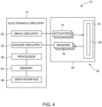
- FIG. 4 is a diagram illustrating an embodiment of the Coriolis flow sensor system 10.
- the Coriolis flow sensor system 10 includes electronics circuitry 12 coupled to three or more actuators 14 and one or more sensors 16.
- the three or more actuators 14 and the sensors 16 are coupled to the flow tube 18.
- the flow tube 18 is enclosed within a flow tube shell 52 that also houses the actuators 14 and sensors 16 to form a Coriolis flow sensor assembly 53.
- the electronics circuitry 12 includes drive circuitry 20 to trigger the one or more actuator(s) 16 to generate oscillations in the flow tube 18 of the desired frequency and magnitude.
- the Coriolis flow sensor system 10 further includes sensor circuitry 22 to receive the Coriolis response from the flow tube 18.
- the electronics circuitry 12 further includes a processor 24 to process the Coriolis response signals received from the sensors 16 to generate one or more measurements representative of one or more properties of the fluid. These measurements are displayed via a user interface 26.
- the electronics circuitry 12 also includes a memory 27 to store the measurements for further use and communication, to store data useful for the drive circuitry 20, and the sensor circuitry 22.
- a flow of a fluid 28 is provided to the flow tube 18.
- the electronics circuitry 12 triggers the three or more actuator(s) 14 to generate oscillations in the flow tube 18, which are transferred to the fluid 28.
- the oscillations in the flow tube 18 are relative to the flow tube shell 52, which essentially remains still.
- the three or more actuators 14 are used to induce oscillations of an appropriate amplitude over a required frequency range in the fluid 28.
- the flow tube shell 52 is pressurized either with liquid or gas, and generally prevents oscillations of the flow tube 18 in directions or planes other than an intended direction of the oscillation. That is, certain frequencies of the oscillation modes of the flow tube 18 may have partial overlap, and these other frequencies may reduce the amplitude of the intended oscillation.
- the oscillation induced (e.g., driven) by the actuators 14 may partially excite unwanted modes.
- the pressurized flow tube shell 52 reduces or prevents the unwanted oscillations, which may reduce the SNR of the intended oscillation.
- the Coriolis response (vibration amplitude and phase) is generated in the fluid and is sensed by the sensors 16 through the flow tube 18.
- the sensed Coriolis response signal from the sensors 16 are transmitted to the electronics circuitry 12 for further processing to obtain the measurements of the one or more properties of the fluid including fluid flow.
- the one or more sensors 16 are configured to provide signals indicative of a Coriolis response caused by the fluid 28 flowing through the flow tube 18.
- the one or more sensors 16 may include, for example, electromagnetic sensors, or optical sensors, and associated components.
- the system 10 may be used to assess fluid characteristics in any fluid flow system. As disclosed, the fluid characteristics may be assessed during operation of a variety of manufacturing and/or fluid flow processes. Some applications for the system 10 described herein include fabrication of wafers in semi-conductor industry, and medical applications that involve use of organic fluids. Some of these are high purity applications, and use of flow tube 18 made of for example polymer, or other chemically inert material is advantageous in such applications. In some other applications, a flow tube 18 formed of electrically inert and low thermal conductivity material like glass is advantageous.
- one or more components of the sensor assembly 14 may be configured as disposable parts, and that other components may be configured as re-usable resident parts.
- the disposable components may be separable (e.g., by an operator using appropriate tools or by hand) from the resident parts.
- at least one of the flow tubes 18, the three or more actuators 14, or the one or more sensors 16 may be disposable parts, and other parts are configured as reusable resident parts.
- the disposable part(s) may be replaced at very low cost in intervals governed by the specific process needs.
- the flow tube 18 may be changed), without the need for replacement of the entire Coriolis flow sensor.
- the disposable-part sub-system allows obtaining high accuracy measurements, reusing of part of the Coriolis flow sensor system 10, provides a flexibility for single-use applications, and achieves cost and material savings.
- the flow tube 18 may be configured as a conduit with an internal passage that permits fluid flow and may be formed in a shape including, but not limited to single, dual or multi loop configurations, split flow, straight tube, counter- or co-flow configurations.
- the flow tube 18 is made from, for example, a polymer whose influence on the oscillation modes (harmonic frequencies) of the mechanical oscillator is not dominant.
- the flow tube 18 is made of metal.
- the flow tube 18 is made of glass.
- the flow tube material in some examples, is tailored to specific requirements of the bioprocessing application, such as temperature, pressure, and the characteristics of the fluid to be measured (e.g., corrosivity).
- the flow tube 18 may be implemented with wall thickness or material features to promote the variable stiffness along its length as provided herein.
- the flow tube 18 may be arranged to permit in-line fluid flow sensing for a fluid processing system. Accordingly, the flow tube may be in fluid communication with fluid conduits of a larger fluid processing system.
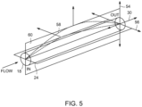
- FIG. 5 is a schematic illustration of a vertical axis 54 and a lateral axis 56 along a flow tube 18.
- the oscillation 58 occurs in a plane 60 spanning the vertical axis 54 and the flow axis 30.
- Unwanted harmonic modes e.g., structural modes
- additional structural features may be added.
- Structural features along certain axes may provide independent influence on the different vibration modes with a variable cross section that adjusts (e.g., shift the frequency of the harmonic mode up, shift the frequency down, or decrease the amplitude) the unwanted harmonic modes until the effect of the unwanted harmonic modes is negligibly, resulting in increased sensitivity and robustness of the Coriolis flow sensor assembly.
- the features that alter the unwanted harmonic modes may have various designs, structures, and properties to address different modes.
- FIG. 6 is a partial cutaway view of a Coriolis flow sensor assembly 53 that includes flow tube 18 (e.g., a primary tube) and a flow tube shell 52 (e.g., secondary tube) of the Coriolis flow sensor system 10.
- the flow tube includes a plurality of sensors 16 that are disposed on the outer surface 34 of the flow tube and may operate as described herein.
- the flow tube shell 52 is coaxial (e.g., about the flow path 30 with the flow tube 18. Further, the flow tube shell 52 surrounds the flow tube 18 such that a gap 62 is formed between the flow tube shell 52 and the flow tube 18.
- the gap 62 may be pressurized with a fluid (e.g., a liquid or gas).
- the gap 62 generally surrounds a portion 64 of the flow tube 18 along the flow path 30.
- portion 64 surrounded by the gap 62 would have a suitable length (e.g., 20%, 40%, 60%, 80%, less than 100% of the total length of the tube.) of a portion 64 of the flow tube 18 where the flow tube 18 may oscillate under operation.
- the flow tube shell 52 is in contact with (e.g., attached to) the ends 66 of the flow tube 18 or couples to a coupling joint 67 coupling the flow tube 18 to the system 10, and connection between the flow tube 18 and the flow tube shell 52 at the ends 66 may maintain the pressure within the gap 62.
- the flow tube 18 may be composed of a more flexible material than the flow tube shell 52.
- the flow tube assembly 53 may be separable from the system 10 and may be provided as a unitary assembly.
- a transmitter 68 is generally aligned on a central axis 70 of the flow tube 18 and the flow tube shell 52.
- the transmitter 68 sends signals to the actuator 14 that drives an oscillation of the flow tube at a frequency, as discussed herein.
- the transmitter 68 may receive signals from the sensors 16.
- the transmitter 68 may include circuitry for managing (e.g., sending signals) to the sensor(s) 16 and the actuator(s) 14.
- the transmitter 68 may provide an interface to the user, either through a visual display or on an electronic interface (e.g., RS-232).
- the actuator 14 is disposed near the center axis 70, it would be appreciated by one of ordinary skill in the art that the location of the actuator 14 may depend on the mode of the oscillation. For example, a suitable position for an actuator 14 may be some fraction along the portion 64 of the flow tube 18. Further, as discussed herein, the Coriolis flow system 10 may include multiple actuators 14 that each drive an oscillation at a frequency/location.
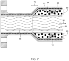
- FIG. 7 shows a cross section along the flow path 30 of the flow tube 18 that is surrounded by the flow tube shell 52, as show in FIG. 6 .
- the outer surface 34 of the flow tube 18 is in contact with the pressurized gap 62.
- the distance 69 between the outer surface 34 of the flow tube 18 and flow tube shell 52 may be any suitable distance 69 that does not restrict the oscillation(s) of the flow tube 18.
- FIG. 7 also shows a transition region 72 between one end 66 of the flow tube 18 and flow tube shell 52.
- the transition region 72 may have any suitable shape between the end 66 where the flow tube 18 is in contact with the flow tube shell 52 and the portion 64 having the gap 62.
- another embodiment of the present disclosure is directed to a Coriolis flow sensor system having a flow tube and a flow tube shell.
- a pressurized gap between the flow tube and the flow tube shell reduces effects of unwanted oscillations.
- One or more actuators and one or more sensors may be disposed within the flow tube shell.
- the sensors may be disposed on the flow tube and the actuators may be disposed radially around the flow tube about the flow path.
- the Coriolis flow sensor system 10 may include multiple actuators 14 and multiple sensors 16.
- the multiple actuators 14 may drive multiple oscillations.
- complex oscillations may be driven at various frequencies.
- FIG. 8 shows the oscillation position 74 (e.g., oscillation driven in the axes 54 and 56, shown in FIG. 5 , as a function of time) with three different oscillation frequencies 76, 78, and 80. That is, the oscillation of the flow tube 18 may be a combination of multiple oscillations.
Landscapes
- Physics & Mathematics (AREA)
- Fluid Mechanics (AREA)
- General Physics & Mathematics (AREA)
- Engineering & Computer Science (AREA)
- Signal Processing (AREA)
- Measuring Volume Flow (AREA)
Claims (14)
- Coriolis-Durchflusssensorsystem (10), umfassend:ein Durchflussrohr (18), das konfiguriert ist, um einen Durchflussweg durch das Durchflussrohr hindurch bereitzustellen;eine Vielzahl von Betätigungsvorrichtungen (14), die radial um das Durchflussrohr (18) herum verteilt sind, wobei eine erste Betätigungsvorrichtung (14a) der Vielzahl von Betätigungsvorrichtungen konfiguriert ist, um eine erste Schwingung in einer ersten Ebene (32a) anzutreiben, und eine zweite Betätigungsvorrichtung (14b) der Vielzahl von Betätigungsvorrichtungen konfiguriert ist, um eine zweite Schwingung in einer zweiten Ebene (32b) anzutreiben; undeine Vielzahl von Sensorsätzen (16), die an dem Durchflussrohr (18) angeordnet sind, wobei jeder Sensorsatz (18) zwei oder mehr Sensoren umfasst, die konfiguriert sind, um die erste Schwingung, die zweite Schwingung oder beide zu erfassen; und wobeidas Durchflussrohr (18) mindestens teilweise von einer druckbeaufschlagten Durchflussrohrhülle (52) umgeben ist, die koaxial zum Durchflussrohr (18) ist, wobei eine dritte Betätigungsvorrichtung (14c) der Vielzahl von Betätigungsvorrichtungen konfiguriert ist, um eine dritte Schwingung in einer dritten Ebene (32c) anzutreiben, und dadurch gekennzeichnet, dass die zweite Betätigungsvorrichtung (14b) radial um etwa 45 Grad von der ersten Betätigungsvorrichtung (14a) versetzt ist und die dritte Betätigungsvorrichtung (14c) radial um etwa 90 Grad von der ersten Betätigungsvorrichtung (14a) versetzt ist.
- Coriolis-Durchflusssensorsystem (10) nach einem vorstehenden Anspruch, wobei die erste Betätigungsvorrichtung (14a) einer anderen Betätigungsvorrichtung (14) der Vielzahl von Betätigungsvorrichtungen (14) gegenüberliegend um das Durchflussrohr (18) herum angeordnet ist.
- Coriolis-Durchflusssensorsystem (10) nach einem vorstehenden Anspruch, wobei eine Frequenz jeder Schwingung, die von jeder Betätigungsvorrichtung (14) angetrieben wird, unterschiedlich ist.
- Coriolis-Durchflusssensorsystem (10) nach einem vorstehenden Anspruch, wobei jeder Sensorsatz (16) einen ersten Sensor (16a) umfasst, der entlang einer Länge des Durchflussrohrs (18) von einem zweiten Sensor (16b) beabstandet ist.
- Coriolis-Durchflusssensorsystem (10) nach einem vorstehenden Anspruch, wobei das Durchflussrohr (18) und jeder Sensor (16) der Vielzahl von Sensoren (16) konfiguriert sind, um reversibel mit einer Fluiddurchflussanordnung (31) gekoppelt zu werden.
- Coriolis-Durchflusssensorsystem (10) nach einem vorstehenden Anspruch, wobei jede Schwingung an einem mittleren Abschnitt des Durchflussrohrs (18) angetrieben wird.
- Coriolis-Durchflusssensorsystem (10) nach einem vorstehenden Anspruch, wobei das Durchflussrohr (18) mit der druckbeaufschlagten Durchflussrohrhülle (52) einen Spalt (62) bildet, und wobei der Spalt (62) mindestens einen Abschnitt des Durchflussrohrs (18) entlang des Durchflussweges umgibt.
- Coriolis-Durchflusssensorsystem (10) nach Anspruch 7, wobei ein von dem Spalt (62) umgebener Abschnitt (64) eine Länge aufweist, die 20%, 40%, 60%, 80%, oder weniger als 100% einer Gesamtlänge des Durchflussrohrs (18) beträgt.
- Coriolis-Durchflusssensorsystem (10) nach Anspruch 7 oder 8, wobei der Spalt (62) mit einem Gas oder einer Flüssigkeit druckbeaufschlagt wird.
- Coriolis-Durchflusssensorsystem (10) nach einem vorstehenden Anspruch, das weiter einen Sender (68) umfasst, der allgemein auf einer Mittelachse (70) des Durchflussrohrs (18) und der Durchflussrohrhülle (52) ausgerichtet ist, wobei der Sender (68) betreibbar ist, um Signale an die Betätigungsvorrichtungen (14) zu senden, um eine Schwingung des Durchflussrohrs (18) anzutreiben.
- Coriolis-Durchflusssensorsystem (10) nach einem vorstehenden Anspruch, wobei das Durchflussrohr (18) dünnere Wände aufweist und/oder weniger starr ist als die Durchflussrohrhülle (52).
- Verfahren (40) zum Bestimmen einer Eigenschaft eines Fluids (28) unter Verwendung des Coriolis-Durchflusssensorsystems (10) nach einem vorstehenden Anspruch, umfassend:Betätigen (42) eines Durchflussrohrs (18) mit einer ersten Betätigungsvorrichtung (14a), um das Durchflussrohr zu veranlassen, in einer ersten Ebene (32a) zu schwingen, wobei das Durchflussrohr ein Fluid (28) aufweist, das entlang eines Durchflussweges fließt;Messen (44) einer ersten Schwingung des Durchflussrohrs (18) in der ersten Ebene (32a);Betätigen (46) des Durchflussrohrs (18) mit einer zweiten Betätigungsvorrichtung (14b), um das Durchflussrohr zu veranlassen, in einer zweiten Ebene (32b) zu schwingen;Messen (48) einer zweiten Schwingung des Durchflussrohrs (18) in der zweiten Ebene (32b); undBestimmen (50) einer Eigenschaft des Fluids (28) auf Basis der gemessenen ersten Schwingung und gemessenen zweiten Schwingung.
- Verfahren (40) nach Anspruch 12, weiter umfassend:Betätigen des Durchflussrohrs (18) mit einer dritten Betätigungsvorrichtung (14c), um das Durchflussrohr zu veranlassen, in einer dritten Ebene (32c) zu schwingen; undMessen einer dritten Schwingung des Durchflussrohrs (18) in der dritten Ebene (32c);wobei Bestimmen der Eigenschaft des Fluids (28) zum Teil auf der gemessenen dritten Schwingung basiert.
- Verfahren (40) nach Anspruch 12 oder 13, wobei Bestimmen der Eigenschaft des Fluids (28) mindestens zum Teil auf einer Amplitude der ersten Schwingung und der zweiten Schwingung basiert und/oder wobei die erste Schwingung auf einer in Bezug zur zweiten Schwingung unterschiedlichen Frequenz erfolgt.
Applications Claiming Priority (2)
| Application Number | Priority Date | Filing Date | Title |
|---|---|---|---|
| US15/960,296 US10598531B2 (en) | 2018-04-23 | 2018-04-23 | Coriolis flow meter with multiple actuators arranged on a flow tube and driven in different planes |
| PCT/EP2019/060109 WO2019206811A1 (en) | 2018-04-23 | 2019-04-18 | Coriolis flow meter with multiple actuators |
Publications (2)
| Publication Number | Publication Date |
|---|---|
| EP3784993A1 EP3784993A1 (de) | 2021-03-03 |
| EP3784993B1 true EP3784993B1 (de) | 2024-10-09 |
Family
ID=66240147
Family Applications (1)
| Application Number | Title | Priority Date | Filing Date |
|---|---|---|---|
| EP19718698.4A Active EP3784993B1 (de) | 2018-04-23 | 2019-04-18 | Coriolis-durchflussmesser mit mehreren aktuatoren |
Country Status (5)
| Country | Link |
|---|---|
| US (1) | US10598531B2 (de) |
| EP (1) | EP3784993B1 (de) |
| JP (1) | JP2021522482A (de) |
| CN (1) | CN112136025B (de) |
| WO (1) | WO2019206811A1 (de) |
Families Citing this family (1)
| Publication number | Priority date | Publication date | Assignee | Title |
|---|---|---|---|---|
| US11266370B2 (en) * | 2020-01-28 | 2022-03-08 | GE Precision Healthcare LLC | Methods and systems for operating an electronic system |
Citations (4)
| Publication number | Priority date | Publication date | Assignee | Title |
|---|---|---|---|---|
| US5448921A (en) * | 1991-02-05 | 1995-09-12 | Direct Measurement Corporation | Coriolis mass flow rate meter |
| US6041665A (en) * | 1996-05-29 | 2000-03-28 | Krohne A.G. | Mass flow meter which operates according to the coriolos principle |
| US20140311255A1 (en) * | 2013-04-22 | 2014-10-23 | Argosy Technologies | Single Straight Tube Flowmeter and Method of Flow Measurement |
| US20160187176A1 (en) * | 2014-12-29 | 2016-06-30 | Concentric Meter Corporation | Fluid parameter sensor and meter |
Family Cites Families (22)
| Publication number | Priority date | Publication date | Assignee | Title |
|---|---|---|---|---|
| US5497665A (en) * | 1991-02-05 | 1996-03-12 | Direct Measurement Corporation | Coriolis mass flow rate meter having adjustable pressure and density sensitivity |
| US7784360B2 (en) | 1999-11-22 | 2010-08-31 | Invensys Systems, Inc. | Correcting for two-phase flow in a digital flowmeter |
| US6164140A (en) * | 1998-10-09 | 2000-12-26 | Kalinoski; Richard W. | Solid state transducer for Coriolis flowmeter |
| JP3224788B2 (ja) * | 1999-03-02 | 2001-11-05 | 株式会社オーバル | 直管シングルチューブコリオリ流量計 |
| ITPR20000038A1 (it) * | 2000-06-01 | 2001-12-01 | Marco Amabili | Misuratore di portata a vibrazioni di guscio con masse aggiunte |
| US6684715B1 (en) * | 2000-09-01 | 2004-02-03 | Fmc Technologies, Inc. | Coriolis mass flowmeter with improved accuracy and simplified instrumentation |
| US6606573B2 (en) * | 2001-08-29 | 2003-08-12 | Micro Motion, Inc. | Sensor apparatus, methods and computer program products employing vibrational shape control |
| WO2004011894A1 (en) | 2002-07-25 | 2004-02-05 | Carpenter Brent L | Precise pressure measurement by vibrating an oval conduit along different cross-sectional axes |
| JP4565150B2 (ja) | 2003-05-12 | 2010-10-20 | 独立行政法人産業技術総合研究所 | コリオリ流量計 |
| DE10331126B4 (de) | 2003-07-09 | 2005-09-01 | Krohne Ag | Coriolis-Massendurchflußmeßgerät und Verfahren zum Betreiben eines Coriolis-Massendurchflußmeßgeräts |
| US7181982B2 (en) | 2003-12-12 | 2007-02-27 | Endress + Hauser Flowtec Ag | Coriolis mass flow measuring device |
| US7073396B2 (en) * | 2004-05-26 | 2006-07-11 | Krohne Ag | Coriolis mass flowmeter |
| DE102004056235A1 (de) * | 2004-10-29 | 2006-05-04 | Krohne Ag | Verfahren zum Betreiben eines Massendurchflußmeßgeräts |
| CA2602863C (en) * | 2005-03-29 | 2013-03-19 | Micro Motion, Inc. | Coriolis flow meter and method for determining flow characteristics |
| NL1031185C2 (nl) * | 2006-02-17 | 2007-09-03 | Lemnis Lighting Ip Gmbh | Verlichtingsinrichting en verlichtingssysteem voor het bevorderen van plantengroei en werkwijze voor het vervaardigen en bedrijven van een verlichtingsinrichting. |
| JP5086814B2 (ja) | 2008-01-07 | 2012-11-28 | 株式会社キーエンス | 流量計 |
| MX2011004353A (es) * | 2008-11-13 | 2011-05-24 | Micro Motion Inc | Metodo y aparato de medicion de parametro de fluido en medidor de vibracion. |
| KR101329033B1 (ko) * | 2011-04-20 | 2013-11-14 | 주식회사 실리콘밸류 | 유동층 반응기 |
| JP6416092B2 (ja) * | 2012-08-21 | 2018-10-31 | マイクロ モーション インコーポレイテッド | 改良されたメータゼロに関するコリオリ流量計および方法 |
| WO2015020172A1 (ja) * | 2013-08-08 | 2015-02-12 | 株式会社フルヤ金属 | 温度計 |
| US9689736B2 (en) * | 2014-10-31 | 2017-06-27 | Invensys Systems, Inc. | Method to provide a quality measure for meter verification results |
| DE102016103048B3 (de) | 2016-02-22 | 2017-04-20 | Krohne Messtechnik Gmbh | Verfahren zum Betreiben eines Coriolis-Massedurchflussmessgeräts |
-
2018
- 2018-04-23 US US15/960,296 patent/US10598531B2/en active Active
-
2019
- 2019-04-18 EP EP19718698.4A patent/EP3784993B1/de active Active
- 2019-04-18 JP JP2020558941A patent/JP2021522482A/ja active Pending
- 2019-04-18 CN CN201980027472.7A patent/CN112136025B/zh active Active
- 2019-04-18 WO PCT/EP2019/060109 patent/WO2019206811A1/en not_active Ceased
Patent Citations (4)
| Publication number | Priority date | Publication date | Assignee | Title |
|---|---|---|---|---|
| US5448921A (en) * | 1991-02-05 | 1995-09-12 | Direct Measurement Corporation | Coriolis mass flow rate meter |
| US6041665A (en) * | 1996-05-29 | 2000-03-28 | Krohne A.G. | Mass flow meter which operates according to the coriolos principle |
| US20140311255A1 (en) * | 2013-04-22 | 2014-10-23 | Argosy Technologies | Single Straight Tube Flowmeter and Method of Flow Measurement |
| US20160187176A1 (en) * | 2014-12-29 | 2016-06-30 | Concentric Meter Corporation | Fluid parameter sensor and meter |
Also Published As
| Publication number | Publication date |
|---|---|
| WO2019206811A1 (en) | 2019-10-31 |
| CN112136025A (zh) | 2020-12-25 |
| CN112136025B (zh) | 2025-03-14 |
| JP2021522482A (ja) | 2021-08-30 |
| US20190323872A1 (en) | 2019-10-24 |
| US10598531B2 (en) | 2020-03-24 |
| EP3784993A1 (de) | 2021-03-03 |
Similar Documents
| Publication | Publication Date | Title |
|---|---|---|
| EP0867694B1 (de) | Coriolis-Massendurchflussmesser | |
| CA2754682C (en) | Measuring system for media flowing in a pipeline | |
| US4831885A (en) | Acoustic wave supressor for Coriolis flow meter | |
| US4823614A (en) | Coriolis-type mass flowmeter | |
| US7185526B2 (en) | Flowmeter calibration techniques | |
| JP6089113B2 (ja) | 横モードの剛性を決定することにより、振動計における流体チューブの断面領域の変化の検出 | |
| US10393560B2 (en) | Mass flow meter including a flexible plate | |
| US10598531B2 (en) | Coriolis flow meter with multiple actuators arranged on a flow tube and driven in different planes | |
| EP0286670A1 (de) | Densitätsunempfindlicher massendurchflussmesser nach dem coriolisprinzip. | |
| WO2016141628A1 (zh) | 一种质量流量传感器 | |
| US10422678B2 (en) | Coriolis flow sensor assembly | |
| US6598488B1 (en) | Coriolis effect fluid flow meter | |
| US12072271B2 (en) | Planar vibratory viscometer, viscometer member, and related method | |
| US9593973B2 (en) | Measuring transducer of vibration-type as well as measuring system formed therwith | |
| US20220107215A1 (en) | Micro-coriolis mass flow sensor with strain measurement devices | |
| EP2815220B1 (de) | Druckmessgerät | |
| EP3377874B1 (de) | Torsionswellenbasierte fluiddichtemessvorrichtung und verfahren | |
| US11821775B2 (en) | Mass flow meter | |
| WO1995033981A1 (en) | Mass flow sensor | |
| RU2532580C1 (ru) | Способ работы прямоточного однотрубного массового расходомера и устройство для его осуществления | |
| Hussain | Single straight tube mass flowmeter using adaptive sensor technology |
Legal Events
| Date | Code | Title | Description |
|---|---|---|---|
| STAA | Information on the status of an ep patent application or granted ep patent |
Free format text: STATUS: UNKNOWN |
|
| STAA | Information on the status of an ep patent application or granted ep patent |
Free format text: STATUS: THE INTERNATIONAL PUBLICATION HAS BEEN MADE |
|
| PUAI | Public reference made under article 153(3) epc to a published international application that has entered the european phase |
Free format text: ORIGINAL CODE: 0009012 |
|
| STAA | Information on the status of an ep patent application or granted ep patent |
Free format text: STATUS: REQUEST FOR EXAMINATION WAS MADE |
|
| 17P | Request for examination filed |
Effective date: 20200915 |
|
| AK | Designated contracting states |
Kind code of ref document: A1 Designated state(s): AL AT BE BG CH CY CZ DE DK EE ES FI FR GB GR HR HU IE IS IT LI LT LU LV MC MK MT NL NO PL PT RO RS SE SI SK SM TR |
|
| AX | Request for extension of the european patent |
Extension state: BA ME |
|
| DAV | Request for validation of the european patent (deleted) | ||
| DAX | Request for extension of the european patent (deleted) | ||
| STAA | Information on the status of an ep patent application or granted ep patent |
Free format text: STATUS: EXAMINATION IS IN PROGRESS |
|
| 17Q | First examination report despatched |
Effective date: 20221007 |
|
| P01 | Opt-out of the competence of the unified patent court (upc) registered |
Effective date: 20230526 |
|
| GRAP | Despatch of communication of intention to grant a patent |
Free format text: ORIGINAL CODE: EPIDOSNIGR1 |
|
| STAA | Information on the status of an ep patent application or granted ep patent |
Free format text: STATUS: GRANT OF PATENT IS INTENDED |
|
| INTG | Intention to grant announced |
Effective date: 20240515 |
|
| GRAS | Grant fee paid |
Free format text: ORIGINAL CODE: EPIDOSNIGR3 |
|
| GRAA | (expected) grant |
Free format text: ORIGINAL CODE: 0009210 |
|
| STAA | Information on the status of an ep patent application or granted ep patent |
Free format text: STATUS: THE PATENT HAS BEEN GRANTED |
|
| AK | Designated contracting states |
Kind code of ref document: B1 Designated state(s): AL AT BE BG CH CY CZ DE DK EE ES FI FR GB GR HR HU IE IS IT LI LT LU LV MC MK MT NL NO PL PT RO RS SE SI SK SM TR |
|
| REG | Reference to a national code |
Ref country code: CH Ref legal event code: EP |
|
| REG | Reference to a national code |
Ref country code: DE Ref legal event code: R096 Ref document number: 602019060034 Country of ref document: DE |
|
| REG | Reference to a national code |
Ref country code: IE Ref legal event code: FG4D |
|
| REG | Reference to a national code |
Ref country code: LT Ref legal event code: MG9D |
|
| REG | Reference to a national code |
Ref country code: NL Ref legal event code: MP Effective date: 20241009 |
|
| REG | Reference to a national code |
Ref country code: AT Ref legal event code: MK05 Ref document number: 1731021 Country of ref document: AT Kind code of ref document: T Effective date: 20241009 |
|
| PG25 | Lapsed in a contracting state [announced via postgrant information from national office to epo] |
Ref country code: NL Free format text: LAPSE BECAUSE OF FAILURE TO SUBMIT A TRANSLATION OF THE DESCRIPTION OR TO PAY THE FEE WITHIN THE PRESCRIBED TIME-LIMIT Effective date: 20241009 |
|
| PG25 | Lapsed in a contracting state [announced via postgrant information from national office to epo] |
Ref country code: NL Free format text: LAPSE BECAUSE OF FAILURE TO SUBMIT A TRANSLATION OF THE DESCRIPTION OR TO PAY THE FEE WITHIN THE PRESCRIBED TIME-LIMIT Effective date: 20241009 |
|
| PG25 | Lapsed in a contracting state [announced via postgrant information from national office to epo] |
Ref country code: IS Free format text: LAPSE BECAUSE OF FAILURE TO SUBMIT A TRANSLATION OF THE DESCRIPTION OR TO PAY THE FEE WITHIN THE PRESCRIBED TIME-LIMIT Effective date: 20250209 Ref country code: HR Free format text: LAPSE BECAUSE OF FAILURE TO SUBMIT A TRANSLATION OF THE DESCRIPTION OR TO PAY THE FEE WITHIN THE PRESCRIBED TIME-LIMIT Effective date: 20241009 Ref country code: PT Free format text: LAPSE BECAUSE OF FAILURE TO SUBMIT A TRANSLATION OF THE DESCRIPTION OR TO PAY THE FEE WITHIN THE PRESCRIBED TIME-LIMIT Effective date: 20250210 |
|
| PG25 | Lapsed in a contracting state [announced via postgrant information from national office to epo] |
Ref country code: FI Free format text: LAPSE BECAUSE OF FAILURE TO SUBMIT A TRANSLATION OF THE DESCRIPTION OR TO PAY THE FEE WITHIN THE PRESCRIBED TIME-LIMIT Effective date: 20241009 |
|
| PG25 | Lapsed in a contracting state [announced via postgrant information from national office to epo] |
Ref country code: BG Free format text: LAPSE BECAUSE OF FAILURE TO SUBMIT A TRANSLATION OF THE DESCRIPTION OR TO PAY THE FEE WITHIN THE PRESCRIBED TIME-LIMIT Effective date: 20241009 |
|
| PG25 | Lapsed in a contracting state [announced via postgrant information from national office to epo] |
Ref country code: ES Free format text: LAPSE BECAUSE OF FAILURE TO SUBMIT A TRANSLATION OF THE DESCRIPTION OR TO PAY THE FEE WITHIN THE PRESCRIBED TIME-LIMIT Effective date: 20241009 |
|
| PG25 | Lapsed in a contracting state [announced via postgrant information from national office to epo] |
Ref country code: NO Free format text: LAPSE BECAUSE OF FAILURE TO SUBMIT A TRANSLATION OF THE DESCRIPTION OR TO PAY THE FEE WITHIN THE PRESCRIBED TIME-LIMIT Effective date: 20250109 |
|
| PG25 | Lapsed in a contracting state [announced via postgrant information from national office to epo] |
Ref country code: GR Free format text: LAPSE BECAUSE OF FAILURE TO SUBMIT A TRANSLATION OF THE DESCRIPTION OR TO PAY THE FEE WITHIN THE PRESCRIBED TIME-LIMIT Effective date: 20250110 Ref country code: LV Free format text: LAPSE BECAUSE OF FAILURE TO SUBMIT A TRANSLATION OF THE DESCRIPTION OR TO PAY THE FEE WITHIN THE PRESCRIBED TIME-LIMIT Effective date: 20241009 Ref country code: AT Free format text: LAPSE BECAUSE OF FAILURE TO SUBMIT A TRANSLATION OF THE DESCRIPTION OR TO PAY THE FEE WITHIN THE PRESCRIBED TIME-LIMIT Effective date: 20241009 |
|
| PG25 | Lapsed in a contracting state [announced via postgrant information from national office to epo] |
Ref country code: PL Free format text: LAPSE BECAUSE OF FAILURE TO SUBMIT A TRANSLATION OF THE DESCRIPTION OR TO PAY THE FEE WITHIN THE PRESCRIBED TIME-LIMIT Effective date: 20241009 |
|
| PG25 | Lapsed in a contracting state [announced via postgrant information from national office to epo] |
Ref country code: RS Free format text: LAPSE BECAUSE OF FAILURE TO SUBMIT A TRANSLATION OF THE DESCRIPTION OR TO PAY THE FEE WITHIN THE PRESCRIBED TIME-LIMIT Effective date: 20250109 |
|
| PG25 | Lapsed in a contracting state [announced via postgrant information from national office to epo] |
Ref country code: SM Free format text: LAPSE BECAUSE OF FAILURE TO SUBMIT A TRANSLATION OF THE DESCRIPTION OR TO PAY THE FEE WITHIN THE PRESCRIBED TIME-LIMIT Effective date: 20241009 |
|
| PGFP | Annual fee paid to national office [announced via postgrant information from national office to epo] |
Ref country code: DE Payment date: 20250428 Year of fee payment: 7 |
|
| PG25 | Lapsed in a contracting state [announced via postgrant information from national office to epo] |
Ref country code: DK Free format text: LAPSE BECAUSE OF FAILURE TO SUBMIT A TRANSLATION OF THE DESCRIPTION OR TO PAY THE FEE WITHIN THE PRESCRIBED TIME-LIMIT Effective date: 20241009 |
|
| REG | Reference to a national code |
Ref country code: DE Ref legal event code: R097 Ref document number: 602019060034 Country of ref document: DE |
|
| PG25 | Lapsed in a contracting state [announced via postgrant information from national office to epo] |
Ref country code: EE Free format text: LAPSE BECAUSE OF FAILURE TO SUBMIT A TRANSLATION OF THE DESCRIPTION OR TO PAY THE FEE WITHIN THE PRESCRIBED TIME-LIMIT Effective date: 20241009 |
|
| PGFP | Annual fee paid to national office [announced via postgrant information from national office to epo] |
Ref country code: FR Payment date: 20250424 Year of fee payment: 7 |
|
| PG25 | Lapsed in a contracting state [announced via postgrant information from national office to epo] |
Ref country code: RO Free format text: LAPSE BECAUSE OF FAILURE TO SUBMIT A TRANSLATION OF THE DESCRIPTION OR TO PAY THE FEE WITHIN THE PRESCRIBED TIME-LIMIT Effective date: 20241009 |
|
| PG25 | Lapsed in a contracting state [announced via postgrant information from national office to epo] |
Ref country code: SK Free format text: LAPSE BECAUSE OF FAILURE TO SUBMIT A TRANSLATION OF THE DESCRIPTION OR TO PAY THE FEE WITHIN THE PRESCRIBED TIME-LIMIT Effective date: 20241009 |
|
| PG25 | Lapsed in a contracting state [announced via postgrant information from national office to epo] |
Ref country code: CZ Free format text: LAPSE BECAUSE OF FAILURE TO SUBMIT A TRANSLATION OF THE DESCRIPTION OR TO PAY THE FEE WITHIN THE PRESCRIBED TIME-LIMIT Effective date: 20241009 |
|
| PG25 | Lapsed in a contracting state [announced via postgrant information from national office to epo] |
Ref country code: IT Free format text: LAPSE BECAUSE OF FAILURE TO SUBMIT A TRANSLATION OF THE DESCRIPTION OR TO PAY THE FEE WITHIN THE PRESCRIBED TIME-LIMIT Effective date: 20241009 |
|
| PLBE | No opposition filed within time limit |
Free format text: ORIGINAL CODE: 0009261 |
|
| STAA | Information on the status of an ep patent application or granted ep patent |
Free format text: STATUS: NO OPPOSITION FILED WITHIN TIME LIMIT |
|
| PG25 | Lapsed in a contracting state [announced via postgrant information from national office to epo] |
Ref country code: SE Free format text: LAPSE BECAUSE OF FAILURE TO SUBMIT A TRANSLATION OF THE DESCRIPTION OR TO PAY THE FEE WITHIN THE PRESCRIBED TIME-LIMIT Effective date: 20241009 |
|
| 26N | No opposition filed |
Effective date: 20250710 |
|
| REG | Reference to a national code |
Ref country code: CH Ref legal event code: H13 Free format text: ST27 STATUS EVENT CODE: U-0-0-H10-H13 (AS PROVIDED BY THE NATIONAL OFFICE) Effective date: 20251125 |
|
| PG25 | Lapsed in a contracting state [announced via postgrant information from national office to epo] |
Ref country code: LU Free format text: LAPSE BECAUSE OF NON-PAYMENT OF DUE FEES Effective date: 20250418 |
|
| PG25 | Lapsed in a contracting state [announced via postgrant information from national office to epo] |
Ref country code: MC Free format text: LAPSE BECAUSE OF FAILURE TO SUBMIT A TRANSLATION OF THE DESCRIPTION OR TO PAY THE FEE WITHIN THE PRESCRIBED TIME-LIMIT Effective date: 20241009 |
|
| REG | Reference to a national code |
Ref country code: BE Ref legal event code: MM Effective date: 20250430 |
|
| PG25 | Lapsed in a contracting state [announced via postgrant information from national office to epo] |
Ref country code: BE Free format text: LAPSE BECAUSE OF NON-PAYMENT OF DUE FEES Effective date: 20250430 |
|
| PG25 | Lapsed in a contracting state [announced via postgrant information from national office to epo] |
Ref country code: CH Free format text: LAPSE BECAUSE OF NON-PAYMENT OF DUE FEES Effective date: 20250430 |
|
| PGFP | Annual fee paid to national office [announced via postgrant information from national office to epo] |
Ref country code: GB Payment date: 20260223 Year of fee payment: 8 |
|
| PG25 | Lapsed in a contracting state [announced via postgrant information from national office to epo] |
Ref country code: IE Free format text: LAPSE BECAUSE OF NON-PAYMENT OF DUE FEES Effective date: 20250418 |