EP3784952B1 - Cryogenic fluid dispensing system having a chilling reservoir - Google Patents
Cryogenic fluid dispensing system having a chilling reservoir Download PDFInfo
- Publication number
- EP3784952B1 EP3784952B1 EP19722458.7A EP19722458A EP3784952B1 EP 3784952 B1 EP3784952 B1 EP 3784952B1 EP 19722458 A EP19722458 A EP 19722458A EP 3784952 B1 EP3784952 B1 EP 3784952B1
- Authority
- EP
- European Patent Office
- Prior art keywords
- fluid
- tank
- intermediate fluid
- coil
- storage tank
- Prior art date
- Legal status (The legal status is an assumption and is not a legal conclusion. Google has not performed a legal analysis and makes no representation as to the accuracy of the status listed.)
- Active
Links
Images




Classifications
-
- F—MECHANICAL ENGINEERING; LIGHTING; HEATING; WEAPONS; BLASTING
- F17—STORING OR DISTRIBUTING GASES OR LIQUIDS
- F17C—VESSELS FOR CONTAINING OR STORING COMPRESSED, LIQUEFIED OR SOLIDIFIED GASES; FIXED-CAPACITY GAS-HOLDERS; FILLING VESSELS WITH, OR DISCHARGING FROM VESSELS, COMPRESSED, LIQUEFIED, OR SOLIDIFIED GASES
- F17C5/00—Methods or apparatus for filling containers with liquefied, solidified, or compressed gases under pressures
- F17C5/02—Methods or apparatus for filling containers with liquefied, solidified, or compressed gases under pressures for filling with liquefied gases
-
- F—MECHANICAL ENGINEERING; LIGHTING; HEATING; WEAPONS; BLASTING
- F17—STORING OR DISTRIBUTING GASES OR LIQUIDS
- F17C—VESSELS FOR CONTAINING OR STORING COMPRESSED, LIQUEFIED OR SOLIDIFIED GASES; FIXED-CAPACITY GAS-HOLDERS; FILLING VESSELS WITH, OR DISCHARGING FROM VESSELS, COMPRESSED, LIQUEFIED, OR SOLIDIFIED GASES
- F17C9/00—Methods or apparatus for discharging liquefied or solidified gases from vessels not under pressure
- F17C9/02—Methods or apparatus for discharging liquefied or solidified gases from vessels not under pressure with change of state, e.g. vaporisation
- F17C9/04—Recovery of thermal energy
-
- F—MECHANICAL ENGINEERING; LIGHTING; HEATING; WEAPONS; BLASTING
- F17—STORING OR DISTRIBUTING GASES OR LIQUIDS
- F17C—VESSELS FOR CONTAINING OR STORING COMPRESSED, LIQUEFIED OR SOLIDIFIED GASES; FIXED-CAPACITY GAS-HOLDERS; FILLING VESSELS WITH, OR DISCHARGING FROM VESSELS, COMPRESSED, LIQUEFIED, OR SOLIDIFIED GASES
- F17C5/00—Methods or apparatus for filling containers with liquefied, solidified, or compressed gases under pressures
- F17C5/06—Methods or apparatus for filling containers with liquefied, solidified, or compressed gases under pressures for filling with compressed gases
-
- F—MECHANICAL ENGINEERING; LIGHTING; HEATING; WEAPONS; BLASTING
- F17—STORING OR DISTRIBUTING GASES OR LIQUIDS
- F17C—VESSELS FOR CONTAINING OR STORING COMPRESSED, LIQUEFIED OR SOLIDIFIED GASES; FIXED-CAPACITY GAS-HOLDERS; FILLING VESSELS WITH, OR DISCHARGING FROM VESSELS, COMPRESSED, LIQUEFIED, OR SOLIDIFIED GASES
- F17C6/00—Methods and apparatus for filling vessels not under pressure with liquefied or solidified gases
-
- F—MECHANICAL ENGINEERING; LIGHTING; HEATING; WEAPONS; BLASTING
- F17—STORING OR DISTRIBUTING GASES OR LIQUIDS
- F17C—VESSELS FOR CONTAINING OR STORING COMPRESSED, LIQUEFIED OR SOLIDIFIED GASES; FIXED-CAPACITY GAS-HOLDERS; FILLING VESSELS WITH, OR DISCHARGING FROM VESSELS, COMPRESSED, LIQUEFIED, OR SOLIDIFIED GASES
- F17C2205/00—Vessel construction, in particular mounting arrangements, attachments or identifications means
- F17C2205/03—Fluid connections, filters, valves, closure means or other attachments
- F17C2205/0302—Fittings, valves, filters, or components in connection with the gas storage device
- F17C2205/0323—Valves
-
- F—MECHANICAL ENGINEERING; LIGHTING; HEATING; WEAPONS; BLASTING
- F17—STORING OR DISTRIBUTING GASES OR LIQUIDS
- F17C—VESSELS FOR CONTAINING OR STORING COMPRESSED, LIQUEFIED OR SOLIDIFIED GASES; FIXED-CAPACITY GAS-HOLDERS; FILLING VESSELS WITH, OR DISCHARGING FROM VESSELS, COMPRESSED, LIQUEFIED, OR SOLIDIFIED GASES
- F17C2221/00—Handled fluid, in particular type of fluid
- F17C2221/01—Pure fluids
- F17C2221/012—Hydrogen
-
- F—MECHANICAL ENGINEERING; LIGHTING; HEATING; WEAPONS; BLASTING
- F17—STORING OR DISTRIBUTING GASES OR LIQUIDS
- F17C—VESSELS FOR CONTAINING OR STORING COMPRESSED, LIQUEFIED OR SOLIDIFIED GASES; FIXED-CAPACITY GAS-HOLDERS; FILLING VESSELS WITH, OR DISCHARGING FROM VESSELS, COMPRESSED, LIQUEFIED, OR SOLIDIFIED GASES
- F17C2221/00—Handled fluid, in particular type of fluid
- F17C2221/01—Pure fluids
- F17C2221/013—Carbon dioxide
-
- F—MECHANICAL ENGINEERING; LIGHTING; HEATING; WEAPONS; BLASTING
- F17—STORING OR DISTRIBUTING GASES OR LIQUIDS
- F17C—VESSELS FOR CONTAINING OR STORING COMPRESSED, LIQUEFIED OR SOLIDIFIED GASES; FIXED-CAPACITY GAS-HOLDERS; FILLING VESSELS WITH, OR DISCHARGING FROM VESSELS, COMPRESSED, LIQUEFIED, OR SOLIDIFIED GASES
- F17C2223/00—Handled fluid before transfer, i.e. state of fluid when stored in the vessel or before transfer from the vessel
- F17C2223/01—Handled fluid before transfer, i.e. state of fluid when stored in the vessel or before transfer from the vessel characterised by the phase
- F17C2223/0107—Single phase
- F17C2223/0123—Single phase gaseous, e.g. CNG, GNC
-
- F—MECHANICAL ENGINEERING; LIGHTING; HEATING; WEAPONS; BLASTING
- F17—STORING OR DISTRIBUTING GASES OR LIQUIDS
- F17C—VESSELS FOR CONTAINING OR STORING COMPRESSED, LIQUEFIED OR SOLIDIFIED GASES; FIXED-CAPACITY GAS-HOLDERS; FILLING VESSELS WITH, OR DISCHARGING FROM VESSELS, COMPRESSED, LIQUEFIED, OR SOLIDIFIED GASES
- F17C2223/00—Handled fluid before transfer, i.e. state of fluid when stored in the vessel or before transfer from the vessel
- F17C2223/01—Handled fluid before transfer, i.e. state of fluid when stored in the vessel or before transfer from the vessel characterised by the phase
- F17C2223/0146—Two-phase
- F17C2223/0153—Liquefied gas, e.g. LPG, GPL
- F17C2223/0161—Liquefied gas, e.g. LPG, GPL cryogenic, e.g. LNG, GNL, PLNG
-
- F—MECHANICAL ENGINEERING; LIGHTING; HEATING; WEAPONS; BLASTING
- F17—STORING OR DISTRIBUTING GASES OR LIQUIDS
- F17C—VESSELS FOR CONTAINING OR STORING COMPRESSED, LIQUEFIED OR SOLIDIFIED GASES; FIXED-CAPACITY GAS-HOLDERS; FILLING VESSELS WITH, OR DISCHARGING FROM VESSELS, COMPRESSED, LIQUEFIED, OR SOLIDIFIED GASES
- F17C2223/00—Handled fluid before transfer, i.e. state of fluid when stored in the vessel or before transfer from the vessel
- F17C2223/03—Handled fluid before transfer, i.e. state of fluid when stored in the vessel or before transfer from the vessel characterised by the pressure level
- F17C2223/033—Small pressure, e.g. for liquefied gas
-
- F—MECHANICAL ENGINEERING; LIGHTING; HEATING; WEAPONS; BLASTING
- F17—STORING OR DISTRIBUTING GASES OR LIQUIDS
- F17C—VESSELS FOR CONTAINING OR STORING COMPRESSED, LIQUEFIED OR SOLIDIFIED GASES; FIXED-CAPACITY GAS-HOLDERS; FILLING VESSELS WITH, OR DISCHARGING FROM VESSELS, COMPRESSED, LIQUEFIED, OR SOLIDIFIED GASES
- F17C2223/00—Handled fluid before transfer, i.e. state of fluid when stored in the vessel or before transfer from the vessel
- F17C2223/03—Handled fluid before transfer, i.e. state of fluid when stored in the vessel or before transfer from the vessel characterised by the pressure level
- F17C2223/036—Very high pressure (>80 bar)
-
- F—MECHANICAL ENGINEERING; LIGHTING; HEATING; WEAPONS; BLASTING
- F17—STORING OR DISTRIBUTING GASES OR LIQUIDS
- F17C—VESSELS FOR CONTAINING OR STORING COMPRESSED, LIQUEFIED OR SOLIDIFIED GASES; FIXED-CAPACITY GAS-HOLDERS; FILLING VESSELS WITH, OR DISCHARGING FROM VESSELS, COMPRESSED, LIQUEFIED, OR SOLIDIFIED GASES
- F17C2225/00—Handled fluid after transfer, i.e. state of fluid after transfer from the vessel
- F17C2225/01—Handled fluid after transfer, i.e. state of fluid after transfer from the vessel characterised by the phase
- F17C2225/0107—Single phase
- F17C2225/0123—Single phase gaseous, e.g. CNG, GNC
-
- F—MECHANICAL ENGINEERING; LIGHTING; HEATING; WEAPONS; BLASTING
- F17—STORING OR DISTRIBUTING GASES OR LIQUIDS
- F17C—VESSELS FOR CONTAINING OR STORING COMPRESSED, LIQUEFIED OR SOLIDIFIED GASES; FIXED-CAPACITY GAS-HOLDERS; FILLING VESSELS WITH, OR DISCHARGING FROM VESSELS, COMPRESSED, LIQUEFIED, OR SOLIDIFIED GASES
- F17C2225/00—Handled fluid after transfer, i.e. state of fluid after transfer from the vessel
- F17C2225/01—Handled fluid after transfer, i.e. state of fluid after transfer from the vessel characterised by the phase
- F17C2225/0146—Two-phase
- F17C2225/0153—Liquefied gas, e.g. LPG, GPL
- F17C2225/0161—Liquefied gas, e.g. LPG, GPL cryogenic, e.g. LNG, GNL, PLNG
-
- F—MECHANICAL ENGINEERING; LIGHTING; HEATING; WEAPONS; BLASTING
- F17—STORING OR DISTRIBUTING GASES OR LIQUIDS
- F17C—VESSELS FOR CONTAINING OR STORING COMPRESSED, LIQUEFIED OR SOLIDIFIED GASES; FIXED-CAPACITY GAS-HOLDERS; FILLING VESSELS WITH, OR DISCHARGING FROM VESSELS, COMPRESSED, LIQUEFIED, OR SOLIDIFIED GASES
- F17C2225/00—Handled fluid after transfer, i.e. state of fluid after transfer from the vessel
- F17C2225/03—Handled fluid after transfer, i.e. state of fluid after transfer from the vessel characterised by the pressure level
- F17C2225/036—Very high pressure, i.e. above 80 bars
-
- F—MECHANICAL ENGINEERING; LIGHTING; HEATING; WEAPONS; BLASTING
- F17—STORING OR DISTRIBUTING GASES OR LIQUIDS
- F17C—VESSELS FOR CONTAINING OR STORING COMPRESSED, LIQUEFIED OR SOLIDIFIED GASES; FIXED-CAPACITY GAS-HOLDERS; FILLING VESSELS WITH, OR DISCHARGING FROM VESSELS, COMPRESSED, LIQUEFIED, OR SOLIDIFIED GASES
- F17C2227/00—Transfer of fluids, i.e. method or means for transferring the fluid; Heat exchange with the fluid
- F17C2227/01—Propulsion of the fluid
- F17C2227/0128—Propulsion of the fluid with pumps or compressors
- F17C2227/0135—Pumps
-
- F—MECHANICAL ENGINEERING; LIGHTING; HEATING; WEAPONS; BLASTING
- F17—STORING OR DISTRIBUTING GASES OR LIQUIDS
- F17C—VESSELS FOR CONTAINING OR STORING COMPRESSED, LIQUEFIED OR SOLIDIFIED GASES; FIXED-CAPACITY GAS-HOLDERS; FILLING VESSELS WITH, OR DISCHARGING FROM VESSELS, COMPRESSED, LIQUEFIED, OR SOLIDIFIED GASES
- F17C2227/00—Transfer of fluids, i.e. method or means for transferring the fluid; Heat exchange with the fluid
- F17C2227/01—Propulsion of the fluid
- F17C2227/0128—Propulsion of the fluid with pumps or compressors
- F17C2227/0157—Compressors
-
- F—MECHANICAL ENGINEERING; LIGHTING; HEATING; WEAPONS; BLASTING
- F17—STORING OR DISTRIBUTING GASES OR LIQUIDS
- F17C—VESSELS FOR CONTAINING OR STORING COMPRESSED, LIQUEFIED OR SOLIDIFIED GASES; FIXED-CAPACITY GAS-HOLDERS; FILLING VESSELS WITH, OR DISCHARGING FROM VESSELS, COMPRESSED, LIQUEFIED, OR SOLIDIFIED GASES
- F17C2227/00—Transfer of fluids, i.e. method or means for transferring the fluid; Heat exchange with the fluid
- F17C2227/03—Heat exchange with the fluid
- F17C2227/0302—Heat exchange with the fluid by heating
- F17C2227/0309—Heat exchange with the fluid by heating using another fluid
- F17C2227/0311—Air heating
-
- F—MECHANICAL ENGINEERING; LIGHTING; HEATING; WEAPONS; BLASTING
- F17—STORING OR DISTRIBUTING GASES OR LIQUIDS
- F17C—VESSELS FOR CONTAINING OR STORING COMPRESSED, LIQUEFIED OR SOLIDIFIED GASES; FIXED-CAPACITY GAS-HOLDERS; FILLING VESSELS WITH, OR DISCHARGING FROM VESSELS, COMPRESSED, LIQUEFIED, OR SOLIDIFIED GASES
- F17C2227/00—Transfer of fluids, i.e. method or means for transferring the fluid; Heat exchange with the fluid
- F17C2227/03—Heat exchange with the fluid
- F17C2227/0302—Heat exchange with the fluid by heating
- F17C2227/0327—Heat exchange with the fluid by heating with recovery of heat
-
- F—MECHANICAL ENGINEERING; LIGHTING; HEATING; WEAPONS; BLASTING
- F17—STORING OR DISTRIBUTING GASES OR LIQUIDS
- F17C—VESSELS FOR CONTAINING OR STORING COMPRESSED, LIQUEFIED OR SOLIDIFIED GASES; FIXED-CAPACITY GAS-HOLDERS; FILLING VESSELS WITH, OR DISCHARGING FROM VESSELS, COMPRESSED, LIQUEFIED, OR SOLIDIFIED GASES
- F17C2227/00—Transfer of fluids, i.e. method or means for transferring the fluid; Heat exchange with the fluid
- F17C2227/03—Heat exchange with the fluid
- F17C2227/0337—Heat exchange with the fluid by cooling
- F17C2227/0341—Heat exchange with the fluid by cooling using another fluid
- F17C2227/0353—Heat exchange with the fluid by cooling using another fluid using cryocooler
-
- F—MECHANICAL ENGINEERING; LIGHTING; HEATING; WEAPONS; BLASTING
- F17—STORING OR DISTRIBUTING GASES OR LIQUIDS
- F17C—VESSELS FOR CONTAINING OR STORING COMPRESSED, LIQUEFIED OR SOLIDIFIED GASES; FIXED-CAPACITY GAS-HOLDERS; FILLING VESSELS WITH, OR DISCHARGING FROM VESSELS, COMPRESSED, LIQUEFIED, OR SOLIDIFIED GASES
- F17C2227/00—Transfer of fluids, i.e. method or means for transferring the fluid; Heat exchange with the fluid
- F17C2227/03—Heat exchange with the fluid
- F17C2227/0337—Heat exchange with the fluid by cooling
- F17C2227/0365—Heat exchange with the fluid by cooling with recovery of heat
-
- F—MECHANICAL ENGINEERING; LIGHTING; HEATING; WEAPONS; BLASTING
- F17—STORING OR DISTRIBUTING GASES OR LIQUIDS
- F17C—VESSELS FOR CONTAINING OR STORING COMPRESSED, LIQUEFIED OR SOLIDIFIED GASES; FIXED-CAPACITY GAS-HOLDERS; FILLING VESSELS WITH, OR DISCHARGING FROM VESSELS, COMPRESSED, LIQUEFIED, OR SOLIDIFIED GASES
- F17C2227/00—Transfer of fluids, i.e. method or means for transferring the fluid; Heat exchange with the fluid
- F17C2227/03—Heat exchange with the fluid
- F17C2227/0367—Localisation of heat exchange
- F17C2227/0369—Localisation of heat exchange in or on a vessel
- F17C2227/0372—Localisation of heat exchange in or on a vessel in the gas
-
- F—MECHANICAL ENGINEERING; LIGHTING; HEATING; WEAPONS; BLASTING
- F17—STORING OR DISTRIBUTING GASES OR LIQUIDS
- F17C—VESSELS FOR CONTAINING OR STORING COMPRESSED, LIQUEFIED OR SOLIDIFIED GASES; FIXED-CAPACITY GAS-HOLDERS; FILLING VESSELS WITH, OR DISCHARGING FROM VESSELS, COMPRESSED, LIQUEFIED, OR SOLIDIFIED GASES
- F17C2227/00—Transfer of fluids, i.e. method or means for transferring the fluid; Heat exchange with the fluid
- F17C2227/03—Heat exchange with the fluid
- F17C2227/0367—Localisation of heat exchange
- F17C2227/0369—Localisation of heat exchange in or on a vessel
- F17C2227/0374—Localisation of heat exchange in or on a vessel in the liquid
-
- F—MECHANICAL ENGINEERING; LIGHTING; HEATING; WEAPONS; BLASTING
- F17—STORING OR DISTRIBUTING GASES OR LIQUIDS
- F17C—VESSELS FOR CONTAINING OR STORING COMPRESSED, LIQUEFIED OR SOLIDIFIED GASES; FIXED-CAPACITY GAS-HOLDERS; FILLING VESSELS WITH, OR DISCHARGING FROM VESSELS, COMPRESSED, LIQUEFIED, OR SOLIDIFIED GASES
- F17C2227/00—Transfer of fluids, i.e. method or means for transferring the fluid; Heat exchange with the fluid
- F17C2227/03—Heat exchange with the fluid
- F17C2227/0367—Localisation of heat exchange
- F17C2227/0388—Localisation of heat exchange separate
- F17C2227/0395—Localisation of heat exchange separate using a submerged heat exchanger
-
- F—MECHANICAL ENGINEERING; LIGHTING; HEATING; WEAPONS; BLASTING
- F17—STORING OR DISTRIBUTING GASES OR LIQUIDS
- F17C—VESSELS FOR CONTAINING OR STORING COMPRESSED, LIQUEFIED OR SOLIDIFIED GASES; FIXED-CAPACITY GAS-HOLDERS; FILLING VESSELS WITH, OR DISCHARGING FROM VESSELS, COMPRESSED, LIQUEFIED, OR SOLIDIFIED GASES
- F17C2250/00—Accessories; Control means; Indicating, measuring or monitoring of parameters
- F17C2250/01—Intermediate tanks
-
- F—MECHANICAL ENGINEERING; LIGHTING; HEATING; WEAPONS; BLASTING
- F17—STORING OR DISTRIBUTING GASES OR LIQUIDS
- F17C—VESSELS FOR CONTAINING OR STORING COMPRESSED, LIQUEFIED OR SOLIDIFIED GASES; FIXED-CAPACITY GAS-HOLDERS; FILLING VESSELS WITH, OR DISCHARGING FROM VESSELS, COMPRESSED, LIQUEFIED, OR SOLIDIFIED GASES
- F17C2250/00—Accessories; Control means; Indicating, measuring or monitoring of parameters
- F17C2250/04—Indicating or measuring of parameters as input values
- F17C2250/0404—Parameters indicated or measured
- F17C2250/0408—Level of content in the vessel
-
- F—MECHANICAL ENGINEERING; LIGHTING; HEATING; WEAPONS; BLASTING
- F17—STORING OR DISTRIBUTING GASES OR LIQUIDS
- F17C—VESSELS FOR CONTAINING OR STORING COMPRESSED, LIQUEFIED OR SOLIDIFIED GASES; FIXED-CAPACITY GAS-HOLDERS; FILLING VESSELS WITH, OR DISCHARGING FROM VESSELS, COMPRESSED, LIQUEFIED, OR SOLIDIFIED GASES
- F17C2250/00—Accessories; Control means; Indicating, measuring or monitoring of parameters
- F17C2250/04—Indicating or measuring of parameters as input values
- F17C2250/0404—Parameters indicated or measured
- F17C2250/043—Pressure
-
- F—MECHANICAL ENGINEERING; LIGHTING; HEATING; WEAPONS; BLASTING
- F17—STORING OR DISTRIBUTING GASES OR LIQUIDS
- F17C—VESSELS FOR CONTAINING OR STORING COMPRESSED, LIQUEFIED OR SOLIDIFIED GASES; FIXED-CAPACITY GAS-HOLDERS; FILLING VESSELS WITH, OR DISCHARGING FROM VESSELS, COMPRESSED, LIQUEFIED, OR SOLIDIFIED GASES
- F17C2250/00—Accessories; Control means; Indicating, measuring or monitoring of parameters
- F17C2250/06—Controlling or regulating of parameters as output values
- F17C2250/0605—Parameters
- F17C2250/0636—Flow or movement of content
-
- F—MECHANICAL ENGINEERING; LIGHTING; HEATING; WEAPONS; BLASTING
- F17—STORING OR DISTRIBUTING GASES OR LIQUIDS
- F17C—VESSELS FOR CONTAINING OR STORING COMPRESSED, LIQUEFIED OR SOLIDIFIED GASES; FIXED-CAPACITY GAS-HOLDERS; FILLING VESSELS WITH, OR DISCHARGING FROM VESSELS, COMPRESSED, LIQUEFIED, OR SOLIDIFIED GASES
- F17C2250/00—Accessories; Control means; Indicating, measuring or monitoring of parameters
- F17C2250/07—Actions triggered by measured parameters
- F17C2250/072—Action when predefined value is reached
-
- F—MECHANICAL ENGINEERING; LIGHTING; HEATING; WEAPONS; BLASTING
- F17—STORING OR DISTRIBUTING GASES OR LIQUIDS
- F17C—VESSELS FOR CONTAINING OR STORING COMPRESSED, LIQUEFIED OR SOLIDIFIED GASES; FIXED-CAPACITY GAS-HOLDERS; FILLING VESSELS WITH, OR DISCHARGING FROM VESSELS, COMPRESSED, LIQUEFIED, OR SOLIDIFIED GASES
- F17C2260/00—Purposes of gas storage and gas handling
- F17C2260/02—Improving properties related to fluid or fluid transfer
-
- F—MECHANICAL ENGINEERING; LIGHTING; HEATING; WEAPONS; BLASTING
- F17—STORING OR DISTRIBUTING GASES OR LIQUIDS
- F17C—VESSELS FOR CONTAINING OR STORING COMPRESSED, LIQUEFIED OR SOLIDIFIED GASES; FIXED-CAPACITY GAS-HOLDERS; FILLING VESSELS WITH, OR DISCHARGING FROM VESSELS, COMPRESSED, LIQUEFIED, OR SOLIDIFIED GASES
- F17C2260/00—Purposes of gas storage and gas handling
- F17C2260/04—Reducing risks and environmental impact
- F17C2260/046—Enhancing energy recovery
-
- F—MECHANICAL ENGINEERING; LIGHTING; HEATING; WEAPONS; BLASTING
- F17—STORING OR DISTRIBUTING GASES OR LIQUIDS
- F17C—VESSELS FOR CONTAINING OR STORING COMPRESSED, LIQUEFIED OR SOLIDIFIED GASES; FIXED-CAPACITY GAS-HOLDERS; FILLING VESSELS WITH, OR DISCHARGING FROM VESSELS, COMPRESSED, LIQUEFIED, OR SOLIDIFIED GASES
- F17C2265/00—Effects achieved by gas storage or gas handling
- F17C2265/06—Fluid distribution
- F17C2265/061—Fluid distribution for supply of supplying vehicles
-
- F—MECHANICAL ENGINEERING; LIGHTING; HEATING; WEAPONS; BLASTING
- F17—STORING OR DISTRIBUTING GASES OR LIQUIDS
- F17C—VESSELS FOR CONTAINING OR STORING COMPRESSED, LIQUEFIED OR SOLIDIFIED GASES; FIXED-CAPACITY GAS-HOLDERS; FILLING VESSELS WITH, OR DISCHARGING FROM VESSELS, COMPRESSED, LIQUEFIED, OR SOLIDIFIED GASES
- F17C2265/00—Effects achieved by gas storage or gas handling
- F17C2265/06—Fluid distribution
- F17C2265/063—Fluid distribution for supply of refuelling stations
-
- F—MECHANICAL ENGINEERING; LIGHTING; HEATING; WEAPONS; BLASTING
- F17—STORING OR DISTRIBUTING GASES OR LIQUIDS
- F17C—VESSELS FOR CONTAINING OR STORING COMPRESSED, LIQUEFIED OR SOLIDIFIED GASES; FIXED-CAPACITY GAS-HOLDERS; FILLING VESSELS WITH, OR DISCHARGING FROM VESSELS, COMPRESSED, LIQUEFIED, OR SOLIDIFIED GASES
- F17C2265/00—Effects achieved by gas storage or gas handling
- F17C2265/06—Fluid distribution
- F17C2265/065—Fluid distribution for refuelling vehicle fuel tanks
-
- F—MECHANICAL ENGINEERING; LIGHTING; HEATING; WEAPONS; BLASTING
- F17—STORING OR DISTRIBUTING GASES OR LIQUIDS
- F17C—VESSELS FOR CONTAINING OR STORING COMPRESSED, LIQUEFIED OR SOLIDIFIED GASES; FIXED-CAPACITY GAS-HOLDERS; FILLING VESSELS WITH, OR DISCHARGING FROM VESSELS, COMPRESSED, LIQUEFIED, OR SOLIDIFIED GASES
- F17C2270/00—Applications
- F17C2270/01—Applications for fluid transport or storage
- F17C2270/0134—Applications for fluid transport or storage placed above the ground
- F17C2270/0139—Fuel stations
-
- Y—GENERAL TAGGING OF NEW TECHNOLOGICAL DEVELOPMENTS; GENERAL TAGGING OF CROSS-SECTIONAL TECHNOLOGIES SPANNING OVER SEVERAL SECTIONS OF THE IPC; TECHNICAL SUBJECTS COVERED BY FORMER USPC CROSS-REFERENCE ART COLLECTIONS [XRACs] AND DIGESTS
- Y02—TECHNOLOGIES OR APPLICATIONS FOR MITIGATION OR ADAPTATION AGAINST CLIMATE CHANGE
- Y02E—REDUCTION OF GREENHOUSE GAS [GHG] EMISSIONS, RELATED TO ENERGY GENERATION, TRANSMISSION OR DISTRIBUTION
- Y02E60/00—Enabling technologies; Technologies with a potential or indirect contribution to GHG emissions mitigation
- Y02E60/30—Hydrogen technology
- Y02E60/32—Hydrogen storage
Definitions
- the present disclosure relates generally to cryogenic fluid dispensing systems and, in particular, to a cryogenic fluid dispensing system having a chilling reservoir for cooling the cryogenic fluid prior to dispensing.
- a hydrogen liquid storage tank serves as the primary container for either type of fuel station.
- the advantage of the compressor style fuel station is that cryogenic vapor is pulled from the top of the storage vessel. This removes more heat from the system than pumping liquid from the bottom of the storage container. Thus the compressor solution is better in terms of heat management.
- the disadvantage of the compressor style fuel station is that compressors are notorious for needing repair and are also more energy consumptive that pumps. This is because it is easier to move a given mass flowrate of liquid via pumping than the same mass flowrate of gas via a compressor. Positive displacement pumps can also need repair, but often that maintenance can be managed via replacement of O-rings or other easily replaceable components.
- the compressor style fuel station will warm the hydrogen gas prior to entering the compressor.
- the positive displacement pump style fuel station will vaporize and warm the hydrogen after the pump.
- hydrogen gas is stored in a high pressure buffer tank(s) which are at ambient temperature.
- a common practice is to cool the hydrogen between the buffer tank(s) and the dispenser. This ensures more mass is stored in the vehicle fuel tank than can otherwise be accommodated by ambient temperature hydrogen at 68.9 MPa (10,000 psi). Hence the hydrogen gas is cooled to -40°C (- 40 degrees Fahrenheit) before entering the vehicle fuel tank.
- the hydrogen gas is typically cooled between the buffer tank(s) and the dispenser via chillers, where coolant is pumped or otherwise supplied to the chillers.
- the hydrogen gas is typically cooled between the buffer tank(s) and the dispenser by mixing liquid hydrogen with the warm buffer tank hydrogen gas. If there is a backlog of vehicles being fueled one after the other, this is not an issue. In this case the pump is running pretty much non-stop and the ability to mix is available. However, during off peak hours, the fueling of vehicles is not continuous. If the buffer tank is large enough to accommodate fueling of a few vehicles without running the pump, then it would be desirable to avoid starting the pump for every vehicle. Start stop cycles are a significant contributor to pump seal degradation. US2015/204485 describes a station and method for supplying a flammable fluid fuel.
- the station comprises a first cryogenic tank for storing flammable fuel in the form of a cryogenic liquid, a second cryogenic tank for storing non-flammable gas and an inert gas stored in the form of a cryogenic liquid, a cooling circuit in a heat-exchange relationship with the first tank, the cooling circuit comprising an upstream end connected to the second cryogenic tank for draiwng cryogenic fluid from the second cryogenic tank in order to give up frigories from the fluid of the second cryogenic tank to the first tank, the station comprising a circuit for withdrawing fluid from the second tank.
- the station includes a detector of fuel leaks from the first tank and a controlled member for opening a portion of the withdrawing circuit, the opening member being controlled automatically in response to a detection of a leak by the detector in order to release fluid derived from the second cryogenic tank so as to inert a volume within the station. There is no means by which the temperature of the cryogenic can be better adjusted.
- a system for dispensing a cryogenic fluid is disclosed in accordance with independent claim 1.
- a chilling reservoir or tank containing an intermediate fluid is provided.
- This component replaces the warm hydrogen gas and cold hydrogen mixing component of the pump style fuel station described above.
- hydrogen being vaporized as it travels from a bulk storage tank cools the intermediate fluid whereas the warm hydrogen traveling from a buffer tank is cooled by the intermediate fluid in the chilling reservoir.
- the system uses the intermediate fluid in the chilling reservoir to chill hydrogen gas from an ambient temperature buffer tank before is it sent to a dispenser.
- the intermediate fluid is cooled by cryogenic hydrogen before the warmed hydrogen is sent to the ambient temperature high pressure buffer tank.
- the intermediate fluid acts as a heat battery or heat sink.
- cryogenic fluid a fluid having a normal boiling point below -90°C (-130°F ).
- alternative compressible intermediate fluids may be used.
- alternative fluids include, but are not limited to, neon, propane, ethane, ethylene and carbon monoxide.
- the carbon dioxide chilling reservoir is provided with regulators and pressure builders to ensure it remains close to -40°C (- 40 degrees Fahrenheit).
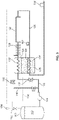
- a first embodiment of the system of the disclosure is presented in Fig. 1 .
- a pump 14 has an inlet in fluid communication with the bulk tank 10 and an outlet connected to line 16a, which is provided with valve 18a.
- Line 16a leads to a heat exchanger coil 22a which is positioned within the headspace of an intermediate fluid storage tank 24a.
- the headspace is formed in tank 24a above an intermediate fluid 26a, which may be carbon dioxide.
- the outlet of the coil 22a is in fluid communication with the inlet of a heat exchanger 28, which may be an ambient heat exchanger.
- the outlet of the heat exchanger 28 is in fluid communication with buffer tank 32. While a single buffer tank 32 is shown, the system may include multiple buffer tanks.
- the outlet of the buffer tank is in fluid communication with the inlet of a chiller coil 34 via line 36.
- the outlet of the chiller coil 34 is connected to a dispenser 38 which may be, as an example only, a nozzle and/or a dispensing valve, and may or may not include a mass flow meter, for refueling a vehicle.
- the outlet of pump 14 is also outlet connected to line 16b, which is provided with valve 18b.
- Line 16b leads to a heat exchanger coil 22b which is positioned within the headspace of an intermediate fluid storage tank 24b.
- the headspace is formed in tank 24b above an intermediate fluid 26b, which may be carbon dioxide.
- the outlet of the coil 22b is in fluid communication with the inlet of a heat exchanger 28.
- the liquid sides of intermediate fluid storage tanks 24a and 24b are selectively in fluid communication with a chilling reservoir or tank 42, within which chiller coil 34 is positioned.
- the chilling reservoir 42 and chiller coil 34 may take the form of a shell and tube heat exchanger.
- line 44a which is equipped with valve 46a, leads from the liquid side of tank 24a to line 48, which leads to the chilling reservoir 42.
- Line 44b which is equipped with valve 46b, leads from the liquid side of tank 24b to line 48.
- a venting line 52 which is provided with vent control valve 54, leads from the headspace of the chilling reservoir 42 to valves 56a and 56b, which selectively communicate with the headspaces of tanks 24a and 24b, respectively.
- Fig. 1 provides two identical sister intermediate fluid (carbon dioxide in the illustrated embodiment) tanks - tank 24a and tank 24b.
- Liquid carbon dioxide may be moved from tank 24a to tank 24b by way of chilling reservoir 42 or from tank 24b to tank 24a by way of chilling reservoir 42, as will be explained below.
- all tanks and piping that handle the hydrogen should be stainless steel.
- handling components should also be made of stainless steel.
- valve 18a is initially open and valve 18b is initially closed.
- activation of pump 14 causes liquid hydrogen to travel to coil 22a, where it is warmed by carbon dioxide vapor in the headspace of tank 24a to near the temperature of the intermediate fluid.
- the warmed hydrogen then travels through ambient heat exchanger 28, where it is warmed to near ambient temperature.
- the resulting hydrogen gas then travels to the buffer tank 32 where it is stored, as an example only, at 68.9 MPa - 103.4 MPa (10,000-15,000 psig) at ambient temperature.
- hydrogen gas from buffer tank 32 flows through chiller coil 34 of the chilling reservoir 42, where it is cooled by liquid carbon dioxide 62 contained within the chilling reservoir 42.
- the cooled hydrogen fluid is then dispensed to the vehicle.
- the hydrogen fuel ideally, but as an example only, equilibrates at -40°C (-40°F) in the chilling reservoir.
- Tanks 24a and 24b may be operated to provide liquid carbon dioxide to reservoir 42.
- valve 46b is initially opened while valve 46a is initially closed.
- tank 24b is controlled to be at 896 kPa (130 psig), which corresponds to a saturation temperature of -40°C (- 40°F) for carbon dioxide.
- Tank 24b may optionally be provided with a pressure building circuit, indicated in phantom at 64b, where intermediate fluid liquid is vaporized in a heat exchanger and directed to the headspace of tank 24b, to accomplish this (tank 24a may optionally be provided with a similar pressure building circuit, indicated in phantom at 64a).
- horizontal intermediate fluid tanks may be desirable in some applications to achieve a better saturated condition for the tanks 24a and 24b.
- tank 24a is controlled to be at 120 psig or less.
- the pressure differential between tanks 24a and 24b drives the liquid carbon dioxide from tank 24b to chilling reservoir 42.
- the liquid carbon dioxide 62 within the chilling reservoir 42 is vaporized and permitted to flow out of the headspace of the chilling reservoir 42 via line 52 under the control of valve 54.
- the system uses a phase change of the intermediate fluid in the chilling reservoir to achieve the desired temperature of the hydrogen fuel.
- the level of the liquid carbon dioxide 62 in the chilling reservoir 42 is controlled (such as through use of valve 54) to ensure that the chiller coil 34 is sufficiently covered to provide cooling of the hydrogen fuel flowing there through.
- valve 56a is open while valve 56b is closed.
- the warm carbon dioxide vapor traveling through line 52 enters the headspace of tank 24a.
- liquid hydrogen traveling through coil 22a cools the headspace so that carbon dioxide vapor in the headspace of tank 24a is condensed and the pressure head collapsed.
- tank 24a becomes the carbon dioxide source tank and tank 24b becomes the carbon dioxide receiving tank.
- tank 24a must be pressurized (for example) to 896 kPa (130 psig), while tank 24b must be depressurized (for example) to 827 kPa (120 psig) or less.
- optional pressure building circuit 64a may be used to build pressure within tank 24a, while tank 24b may be vented.
- the pressures in tanks 24a and 24b may be equalized (such as by temporarily placing their headspaces in fluid communication with one another) and then the pressure building circuit 64a used to build the pressure in tank 24a, while hydrogen flowing through coil 22b is used to reduce the pressure in tank 24b.
- the pressure therein may be allowed to drop as the last portion of liquid carbon dioxide is transferred to chilling reservoir 42.
- tank 24a will become the 130 psig carbon dioxide source tank and tank 24b will be the liquid carbon dioxide receiving tank, and valve 44a must be opened and valve 44b closed.
- valve 18a will need to be closed while valve 18b is opened, to direct liquid hydrogen through coil 22b (instead of through coil 22a), and valve 56a will need to be closed and valve 56b opened, to return carbon dioxide vapor to the headspace of tank 24b instead of tank 24a.
- the pump 14 may be eliminated and a compressor, indicated in phantom at 70, may be added.
- line 16a and 16b are selectively (via valves 18a and 18b) placed in fluid communication with the headspace of bulk liquid hydrogen supply tank 10 via line 71.
- the compressor 70 is activated to pull hydrogen vapor from the headspace of tank 10 through coils 22a or 22b (so that the hydrogen is warmed before the compressor 70), and directed through heat exchanger 28, to fill buffer tank 32.
- the system of Fig. 1 also includes a bypass line 72 and a bypass valve 74.
- the bypass valve 74 may be opened and adjusted so that only a portion of liquid hydrogen from pump 14 is directed through the coils 22a or 22b, depending on whether valve 18a is opened and valve 18b is shut, or valve 18b is opened and valve 18a is shut.
- the liquid hydrogen exiting bypass line 72 rejoins the warmed hydrogen from coils 22a or 22b prior to entry of the resulting stream into heat exchanger 28.
- liquid hydrogen may be selectively directed through either coil 22a or 22b as required to maintain a sufficiently low pressure to drive flow.
- the components of the system within box 76 may be located remotely from the remaining components of the system.
- a third intermediate fluid tank 24c has been added to the embodiment of Fig. 1 . More specifically, the outlet of pump 14 is also connected to line 16c, which is provided with valve 18c. Line 16c leads to a heat exchanger coil 22c which is positioned within the headspace of an intermediate fluid storage tank 24c. The headspace is formed in tank 24c above an intermediate fluid 26c, which may be carbon dioxide. The outlet of the coil 22c is in fluid communication with the inlet of heat exchanger 28.
- An additional line that includes valve 56c selectively places the headspace of tank 26c in fluid communication with the headspace of chilling reservoir 42.
- carbon dioxide tank 26c is selectively in fluid communication with chilling reservoir 42 via line 44c (having valve 46c) and line 48. Otherwise, the system of Fig. 2 is identical to the system of Fig. 1 .
- the third tank 24c of Fig. 2 provides an extra supply of intermediate fluid (carbon dioxide, for example) where the timing of switching between tanks 24a and 24b as the carbon dioxide source and receiving tanks is critical.
- tank 24b is the carbon dioxide source tank (at 896 kPa (130 psig))
- tank 24a is the carbon dioxide vapor receiving tank
- tank 24c contains an additional supply of carbon dioxide 26c at a pressure (for example) of 896 kPa (130 psig), and valves 18c, 46c and 56c are maintained in the closed configuration.
- An optional pressure building circuit 64c may be necessary to pressurize the tank 24c to 896 kPa (130 psig) or other desired pressure.
- valve 46b When the supply of liquid carbon dioxide 26b in tank 24b drops to the level where tank 24b should be switched over to serve as the receiving tank, valve 46b is closed and valve 46c is opened (valve 46a remains closed).
- valve 56b is opened and valve 56a is closed, while valve 18b is opened and valve 18a is closed.
- the pressure within tank 24b may be reduced to (for example) 827 kPa (120 psig) or lower using, for example, one or more of the methods described above.
- Liquid carbon dioxide may be immediately supplied to the chilling reservoir 42 from tank 24c since tank 24c was already filled with liquid carbon dioxide at the correct pressure of (for example) 896 kPa (130 psig). There is no need to wait for tank 24c to be pressurized to 896 kPa (130 psig).
- a bulk storage tank 110 which is preferably jacketed, contains a supply of liquid hydrogen 112.
- a pump 114 has an inlet in fluid communication with the bulk tank 110 and an outlet connected to line 116, which is provided with valve 118.
- Line 116 leads to a heat exchanger coil 122 which is positioned within the headspace of the intermediate fluid storage tank 124.
- the headspace is formed in tank 124 above an intermediate fluid 126, which may be carbon dioxide.
- the outlet of the coil 122 is in fluid communication with the inlet of a heat exchanger 128, which may be an ambient heat exchanger.
- the outlet of the heat exchanger 128 is in fluid communication with buffer tank 132.
- the system may include multiple buffer tanks.
- the outlet of the buffer tank is in fluid communication with the inlet of a chiller coil 134 via line 136.
- the chiller coil is positioned within the intermediate fluid tank 124 so that the intermediate fluid tank also serves as the chilling reservoir.
- the outlet of the chiller coil 134 is connected to a dispenser 138 which may be, as an example only, a nozzle and/or a dispensing valve and/or a mass flow meter for refueling a vehicle.
- a bypass line 140 is provided with a bypass valve 142 and extends between the outlet of pump 114 and the inlet of heat exchanger 128.
- valves 118 and 142 may be adjusted to control the flow rate of liquid hydrogen through the coil 122 and the rest of the system when the pump 114 is activated.
- the warmed hydrogen exiting coil 122 travels through ambient heat exchanger 128, where it is warmed to near ambient temperature.
- the resulting fluid then travels to the buffer tank(s) 132 where it is stored, as an example only, at 68.9 MPa - 103.4 MPa (10,000-15,000 psig) at ambient temperature.
- hydrogen gas from buffer tank 132 flows through chiller coil 134, where it is cooled by liquid carbon dioxide 126 contained within the tank 124.
- the cooled hydrogen fluid is then dispensed to the vehicle.
- the hydrogen fuel ideally, but as an example only, equilibrates at -40°C (-40°F) in the chiller coil 134.
- the heat added to the carbon dioxide 126 via cooling of the hydrogen gas stream flowing through line 136 is countered by the cooling and condensation of the carbon dioxide vapor in the headspace of the tank 124 by coil 122.
- the amount of liquid hydrogen directed through coil 122 (via the setting of valve 118) is selected to maintain the pressure in tank 124 at approximately 896 kPa (130 psig) (for example).
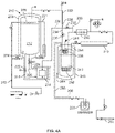
- a bulk storage tank indicated in general at 210 and which is preferably jacketed via jacket 208, contains a supply of liquid hydrogen 212.
- a pump 214 is positioned within a sump 216, which is preferably also positioned within the jacket 208.
- the sump 216 has an inlet in fluid communication with the bulk tank 210 so that it receives liquid from the bulk tank 210 via line 218.
- a return line 220 leads from the top portion of the sump to the bulk tank.
- Bulk tank 210 is provided with a pressure building circuit 221.
- lines 218 and 220 are provided with valves 222 and 224, which permit maintenance on, or removal of, the pump without taking bulk tank 210 out of service.
- the outlet of the pump 214 is in fluid communication with line 226, which leads to junction 228.
- a bypass line 230 exits junction 228 and is provided with a bypass valve 232.
- a vent line 233 exits the headspace of bulk thank 210 and leads to junction 228.
- a line 234 is provided with valve 236 and leads from the junction to a heat exchanger coil 238 which is positioned within the headspace of the intermediate fluid storage tank 240.
- the headspace is formed in tank 240 above an intermediate fluid 242, which may be carbon dioxide.
- the outlet of the coil 238 is in fluid communication via line 244 with the outlet of bypass line 230 and the inlet of a heat exchanger 246, which may be an ambient heat exchanger.
- the outlet of the heat exchanger 246 is in fluid communication with buffer tank 248. While a single buffer tank is shown, the system may include multiple buffer tanks.
- the outlet of the buffer tank is in fluid communication with the inlet of a chiller coil 252 via line 254.
- the chiller coil is positioned within the intermediate fluid tank 240 so that the intermediate fluid tank also serves as the chilling reservoir.
- the outlet of the chiller coil 252 is connected via line 256 to a dispenser 258 for refueling a vehicle via a nozzle 262.
- Line 256 is preferably jacketed via jacket 266.
- the annular space between the jacket 266 and line 256 is connected to the liquid side of tank 240 via liquid line 264.
- intermediate fluid 242 fills the annular space within jacket 266 to keep the liquid hydrogen flowing through line 256 cool as it flows to the dispenser. This is particularly useful if the dispenser 258 is on a fueling island remote from the tank 240 so that line 256 must traverse a greater distance.
- the annular space within the jacket 266 is also in fluid communication with the headspace of tank 240 so that vaporized carbon dioxide may return to the tank.
- the bulk tank 210 is provided with a fill line 272 that is in fluid communication with a bottom fill opening 274 and a spray bar 276.
- a tanker truck 280 containing liquid hydrogen is connected to line 272.
- the liquid flows through line 272 and into the tank via bottom fill opening 274.
- a portion of the liquid hydrogen is directed to spray bar 276 to collapse the vapor pressure within the headspace of tank 210.
- Liquid hydrogen flows from tank 210 through line 218 to sump 216.
- Liquid returns to the sump 216 through line 220 with the liquid level in the sump being maintained at a level whereby pump 214 is submerged.
- Valve 232 is closed, while valve 236 is open.
- Liquid exiting pump 214 travels through line 226 to heat exchanger coil 238, where it is warmed to near the temperature of the intermediate fluid 242.
- the warmed hydrogen exiting coil 238 travels through ambient heat exchanger 246, where it is warmed to near ambient temperature.
- the resulting fluid then travels to the buffer tank(s) 248 where it is stored, as an example only, at 68.9 Mpa - 103.4 Mpa (10,000-15,000 psig) at ambient temperature.
- Fluid from buffer tank 248 flows through chiller coil 252, where it is cooled by the liquid carbon dioxide intermediate fluid 242 contained within the tank 240.
- the cooled hydrogen fluid is then dispensed to the vehicle via lines 256, dispenser 258 and nozzle 262.
- the hydrogen fuel ideally, but as an example only, equilibrates at -40°C (-40°F) in the chiller coil 252.
- the heat added to the carbon dioxide 242 via cooling of the hydrogen gas stream flowing through coil 252 is countered by the cooling and condensation of the carbon dioxide vapor in the headspace of the tank 240 by coil 238.
- the amount of liquid hydrogen directed through coil 238 (via the setting of valve 236) is selected to maintain the pressure in tank 240 at approximately 896 Kpa (130 psig) (for example).
- the system may be configured as illustrated in Fig. 4D to control pressure within the intermediate fluid storage tank 240 by venting cold hydrogen gas from the headspace of tank 210 through line 233 through the coil 238 of tank 240.
- the vapor in the headspace of tank 240 is condensed to reduce the pressure within the tank.
- the warm fluid exiting the coil 238 travels through heat exchanger 246, is warmed, and then is vented to atmosphere through vent circuit 288, where valve 290 has been opened.
- the pump 214 may be serviced by first closing valves 222 and 224 so that liquid from bulk tank 210 no longer flows to the sump 216.
- the sump may then be vented to relieve pressure by opening valve 232 (valve 236 remains open as well) and valve 292 of vent circuit 288.
- opening valve 232 valve 236 remains open as well
- valve 292 of vent circuit 288 valve 292 of vent circuit 288.
- pressure from within the sump is vented through the heat exchanger 246, coil 238 and vent circuit 288.
- the sump 216 may then be drained and the pump 214 removed or accessed for maintenance.
- the line 256 exiting the coil 252 is dropped to a low elevation (buried deeply within the ground, for example) immediately outside the intermediate fluid tank 240.
- the elevation of the line as illustrated in Fig. 5 , then gradually rises as the line approaches the island (294).
- any heat added to the line that would produce vapor would first go to the island 294.
- the resulting intermediate fluid vapor would then be returned to the tank 240 via rising insulated vapor return line 296.
- the embodiments of the disclosure described above therefore use a phase change intermediate fluid to provide heat to the cold liquid hydrogen (from the storage tank to the buffer tank), and to cool the warm hydrogen gas (from the buffer tank to the vehicle).
- hydrogen fuel may be dispensed from a buffer storage tank or tanks and cooled prior to dispensing without activating the pump. They are therefore capable of handling multiple dispenses without the need to activate the pump. Also this system avoids the need for pumping and refrigerating brine solution, thus saving electrical consumption.
- Figs. 1-4A therefore solve the problem of having many start stop cycles for the pumped solution of hydrogen. This solution also eliminates the need for a conventional style chiller for compressor style fuel stations which have liquid hydrogen storage.
- the cooling of the intermediate fluid exceeds that from the warming via the hydrogen going from the buffer tank to the vehicle.
- heat can always be added to the intermediate fluid tank to maintain the desired saturation temperature.
- Embodiments of the disclosure also comply with National Fire Protection Association (NFPA) regulation 55 requirement for the heat exchanger which requires an intermediate heat transfer fluid when hydrogen is processed and/or dispensed.
- NFPA National Fire Protection Association
- venting of the bulk tanks may be required.
- boil off gases in such situations may be removed by opening vent valve 152 so that venting may occur through vent 154.
- hydrogen gas exiting valve 152 may be routed through line 156 and coil 158, which is positioned in the headspace of the chilling reservoir, to capture the cold of these boil off cryogenic hydrogen gases.
- a miniature turbine 162 which burns hydrogen may receive the hydrogen gas exiting coil 158.
- Such a turbine may be used, for example, to direct drive a hydrogen compressor of the system.
Landscapes
- Engineering & Computer Science (AREA)
- Mechanical Engineering (AREA)
- General Engineering & Computer Science (AREA)
- Filling Or Discharging Of Gas Storage Vessels (AREA)
Description
- This application claims the benefit of
U.S. Provisional Application No. 62/662,984, filed April 26, 2018 - The present disclosure relates generally to cryogenic fluid dispensing systems and, in particular, to a cryogenic fluid dispensing system having a chilling reservoir for cooling the cryogenic fluid prior to dispensing.
- Systems for dispensing cryogenic fluids are used in a variety of applications. Due to the increasing interest in alternative vehicle fuels, hydrogen fuel stations, for fueling fuel cell electric vehicles, are growing in popularity. There are both compressor driven and pump driven hydrogen fuel stations. In a typical compressor style fuel station, the hydrogen is sent from either a liquid tank or a gaseous tank to a 103.4 MPa (15,000 psig) buffer storage tank via a compressor. In a typical pump style fuel station, liquid hydrogen is sent to a vaporizer and then on to the 103.4 MPa (15,000 psig) buffer storage tank via a positive displacement pump.
- A hydrogen liquid storage tank serves as the primary container for either type of fuel station. The advantage of the compressor style fuel station is that cryogenic vapor is pulled from the top of the storage vessel. This removes more heat from the system than pumping liquid from the bottom of the storage container. Thus the compressor solution is better in terms of heat management. The disadvantage of the compressor style fuel station is that compressors are notorious for needing repair and are also more energy consumptive that pumps. This is because it is easier to move a given mass flowrate of liquid via pumping than the same mass flowrate of gas via a compressor. Positive displacement pumps can also need repair, but often that maintenance can be managed via replacement of O-rings or other easily replaceable components.
- The compressor style fuel station will warm the hydrogen gas prior to entering the compressor. The positive displacement pump style fuel station will vaporize and warm the hydrogen after the pump.
- In either application, hydrogen gas is stored in a high pressure buffer tank(s) which are at ambient temperature. A common practice is to cool the hydrogen between the buffer tank(s) and the dispenser. This ensures more mass is stored in the vehicle fuel tank than can otherwise be accommodated by ambient temperature hydrogen at 68.9 MPa (10,000 psi). Hence the hydrogen gas is cooled to -40°C (- 40 degrees Fahrenheit) before entering the vehicle fuel tank.
- In the case of the compressor style fuel station, the hydrogen gas is typically cooled between the buffer tank(s) and the dispenser via chillers, where coolant is pumped or otherwise supplied to the chillers.
- In the case of the pump style fuel station, the hydrogen gas is typically cooled between the buffer tank(s) and the dispenser by mixing liquid hydrogen with the warm buffer tank hydrogen gas. If there is a backlog of vehicles being fueled one after the other, this is not an issue. In this case the pump is running pretty much non-stop and the ability to mix is available. However, during off peak hours, the fueling of vehicles is not continuous. If the buffer tank is large enough to accommodate fueling of a few vehicles without running the pump, then it would be desirable to avoid starting the pump for every vehicle. Start stop cycles are a significant contributor to pump seal degradation.
US2015/204485 describes a station and method for supplying a flammable fluid fuel. The station comprises a first cryogenic tank for storing flammable fuel in the form of a cryogenic liquid, a second cryogenic tank for storing non-flammable gas and an inert gas stored in the form of a cryogenic liquid, a cooling circuit in a heat-exchange relationship with the first tank, the cooling circuit comprising an upstream end connected to the second cryogenic tank for draiwng cryogenic fluid from the second cryogenic tank in order to give up frigories from the fluid of the second cryogenic tank to the first tank, the station comprising a circuit for withdrawing fluid from the second tank. The station includes a detector of fuel leaks from the first tank and a controlled member for opening a portion of the withdrawing circuit, the opening member being controlled automatically in response to a detection of a leak by the detector in order to release fluid derived from the second cryogenic tank so as to inert a volume within the station. There is no means by which the temperature of the cryogenic can be better adjusted. - In one aspect, a system for dispensing a cryogenic fluid is disclosed in accordance with independent claim 1.
- In still another aspect, a method for dispensing a cryogenic fluid is disclosed in accordance with independent claim 15.
-
-
Figure 1 is a schematic diagram of a first embodiment of the cryogenic fluid dispensing system of the disclosure; -
Figure 2 is a schematic diagram of a second embodiment of the cryogenic fluid dispensing system of the disclosure; -
Figure 3 is a schematic diagram of a third embodiment of the cryogenic fluid dispensing system of the disclosure; -
Figure 4A is a schematic diagram of a fourth embodiment of the cryogenic fluid dispensing system of the disclosure; -
Figure 4B is a schematic diagram of the system ofFigure 4A illustrating refill of the bulk tank; -
Figure 4C is a schematic diagram of the system ofFigure 4A illustrating a dispensing operation; -
Figure 4D is a schematic diagram of the system ofFigure 4A illustrating a venting operation; -
Figure 4E is a schematic diagram of the system ofFigure 4A illustrating preparation of the system for pump servicing; -
Figure 5 is a schematic diagram of an embodiment of a chiller line. - In a number of embodiments of the present invention, described in greater detail below, a chilling reservoir or tank containing an intermediate fluid is provided. This component replaces the warm hydrogen gas and cold hydrogen mixing component of the pump style fuel station described above. In such a system, hydrogen being vaporized as it travels from a bulk storage tank cools the intermediate fluid whereas the warm hydrogen traveling from a buffer tank is cooled by the intermediate fluid in the chilling reservoir. In other words, the system uses the intermediate fluid in the chilling reservoir to chill hydrogen gas from an ambient temperature buffer tank before is it sent to a dispenser. The intermediate fluid is cooled by cryogenic hydrogen before the warmed hydrogen is sent to the ambient temperature high pressure buffer tank. As a result, the intermediate fluid acts as a heat battery or heat sink.
- While embodiments of the disclosure are described below as dispensing hydrogen, the technology of the disclosure may be used to dispense other cryogenic fluids. As used herein, the terms "cryogenic fluid", "cryogenic liquid" or "cryogen" are defined as meaning a fluid having a normal boiling point below -90°C (-130°F ).
- While carbon dioxide is useful as an intermediate fluid due to the high thermal mass and phase change attributes, and is described as the intermediate fluid in the embodiments presented below, alternative compressible intermediate fluids may be used. Examples of alternative fluids include, but are not limited to, neon, propane, ethane, ethylene and carbon monoxide.
- In embodiments where the cryogenic fluid is hydrogen, the carbon dioxide chilling reservoir is provided with regulators and pressure builders to ensure it remains close to -40°C (- 40 degrees Fahrenheit).
- If carbon dioxide is used as the intermediate fluid, care must be used in the system design to avoid freezing. The -40°C (- 40 degrees Fahrenheit) temperature noted above is above the freeze solid temperature of -78.3°C (- 109 degrees Fahrenheit) for carbon dioxide at ambient pressure. This makes the carbon dioxide temperature controllable by carbon dioxide storage tank pressure regulation.
- A first embodiment of the system of the disclosure is presented in
Fig. 1 . Abulk storage tank 10, which is preferably jacketed, contains a supply ofliquid hydrogen 12. Apump 14 has an inlet in fluid communication with thebulk tank 10 and an outlet connected toline 16a, which is provided withvalve 18a.Line 16a leads to aheat exchanger coil 22a which is positioned within the headspace of an intermediatefluid storage tank 24a. The headspace is formed intank 24a above anintermediate fluid 26a, which may be carbon dioxide. The outlet of thecoil 22a is in fluid communication with the inlet of aheat exchanger 28, which may be an ambient heat exchanger. The outlet of theheat exchanger 28 is in fluid communication withbuffer tank 32. While asingle buffer tank 32 is shown, the system may include multiple buffer tanks. The outlet of the buffer tank is in fluid communication with the inlet of achiller coil 34 vialine 36. The outlet of thechiller coil 34 is connected to adispenser 38 which may be, as an example only, a nozzle and/or a dispensing valve, and may or may not include a mass flow meter, for refueling a vehicle. - The outlet of
pump 14 is also outlet connected toline 16b, which is provided withvalve 18b.Line 16b leads to aheat exchanger coil 22b which is positioned within the headspace of an intermediatefluid storage tank 24b. The headspace is formed intank 24b above anintermediate fluid 26b, which may be carbon dioxide. The outlet of thecoil 22b is in fluid communication with the inlet of aheat exchanger 28. - The liquid sides of intermediate
fluid storage tanks tank 42, within whichchiller coil 34 is positioned. As an example only, the chillingreservoir 42 andchiller coil 34 may take the form of a shell and tube heat exchanger. More specifically,line 44a, which is equipped withvalve 46a, leads from the liquid side oftank 24a toline 48, which leads to thechilling reservoir 42.Line 44b, which is equipped withvalve 46b, leads from the liquid side oftank 24b toline 48. - A venting
line 52, which is provided withvent control valve 54, leads from the headspace of thechilling reservoir 42 tovalves tanks - In view of the above, the system of
Fig. 1 provides two identical sister intermediate fluid (carbon dioxide in the illustrated embodiment) tanks -tank 24a andtank 24b. Liquid carbon dioxide may be moved fromtank 24a totank 24b by way of chillingreservoir 42 or fromtank 24b totank 24a by way of chillingreservoir 42, as will be explained below. - In embodiments where hydrogen is used as the dispensed fluid, all tanks and piping that handle the hydrogen should be stainless steel. When carbon dioxide is used as the intermediate fluid, handling components should also be made of stainless steel.
- As an example of operation of the system of
Fig. 1 , assume thatvalve 18a is initially open andvalve 18b is initially closed. As a result, activation ofpump 14 causes liquid hydrogen to travel tocoil 22a, where it is warmed by carbon dioxide vapor in the headspace oftank 24a to near the temperature of the intermediate fluid. The warmed hydrogen then travels throughambient heat exchanger 28, where it is warmed to near ambient temperature. The resulting hydrogen gas then travels to thebuffer tank 32 where it is stored, as an example only, at 68.9 MPa - 103.4 MPa (10,000-15,000 psig) at ambient temperature. When thedispenser 38 is activated, such as during fueling of a vehicle, hydrogen gas frombuffer tank 32 flows throughchiller coil 34 of thechilling reservoir 42, where it is cooled byliquid carbon dioxide 62 contained within the chillingreservoir 42. The cooled hydrogen fluid is then dispensed to the vehicle. The hydrogen fuel ideally, but as an example only, equilibrates at -40°C (-40°F) in the chilling reservoir. -
Tanks reservoir 42. Continuing with the example of operation presented above,valve 46b is initially opened whilevalve 46a is initially closed. As an example only,tank 24b is controlled to be at 896 kPa (130 psig), which corresponds to a saturation temperature of -40°C (- 40°F) for carbon dioxide.Tank 24b may optionally be provided with a pressure building circuit, indicated in phantom at 64b, where intermediate fluid liquid is vaporized in a heat exchanger and directed to the headspace oftank 24b, to accomplish this (tank 24a may optionally be provided with a similar pressure building circuit, indicated in phantom at 64a). It should be noted that horizontal intermediate fluid tanks may be desirable in some applications to achieve a better saturated condition for thetanks tank 24a is controlled to be at 120 psig or less. - The pressure differential between
tanks tank 24b to chillingreservoir 42. As hydrogen flows throughchiller coil 34 and is cooled, theliquid carbon dioxide 62 within the chillingreservoir 42 is vaporized and permitted to flow out of the headspace of thechilling reservoir 42 vialine 52 under the control ofvalve 54. As a result, the system uses a phase change of the intermediate fluid in the chilling reservoir to achieve the desired temperature of the hydrogen fuel. - The level of the
liquid carbon dioxide 62 in thechilling reservoir 42 is controlled (such as through use of valve 54) to ensure that thechiller coil 34 is sufficiently covered to provide cooling of the hydrogen fuel flowing there through. - In the example of operation presented thus far,
valve 56a is open whilevalve 56b is closed. As a result, the warm carbon dioxide vapor traveling throughline 52 enters the headspace oftank 24a. As noted above, however, liquid hydrogen traveling throughcoil 22a cools the headspace so that carbon dioxide vapor in the headspace oftank 24a is condensed and the pressure head collapsed. - As time goes on, a mass of carbon dioxide will be leaving
tank 24b and accumulating intank 24a. When the carbon dioxide supply withintank 24b approaches a level where the desired liquid level withinchilling reservoir 42 cannot be maintained, the system needs to be reconfigured so thattank 24a becomes the carbon dioxide source tank andtank 24b becomes the carbon dioxide receiving tank. In order to do so,tank 24a must be pressurized (for example) to 896 kPa (130 psig), whiletank 24b must be depressurized (for example) to 827 kPa (120 psig) or less. This may be accomplished in a number of different ways. For example, optionalpressure building circuit 64a may be used to build pressure withintank 24a, whiletank 24b may be vented. Alternatively, the pressures intanks pressure building circuit 64a used to build the pressure intank 24a, while hydrogen flowing throughcoil 22b is used to reduce the pressure intank 24b. As an alternative to ventingtank 24b or usingcoil 22b, the pressure therein may be allowed to drop as the last portion of liquid carbon dioxide is transferred to chillingreservoir 42. - As a result,
tank 24a will become the 130 psig carbon dioxide source tank andtank 24b will be the liquid carbon dioxide receiving tank, andvalve 44a must be opened andvalve 44b closed. In addition,valve 18a will need to be closed whilevalve 18b is opened, to direct liquid hydrogen throughcoil 22b (instead of throughcoil 22a), andvalve 56a will need to be closed andvalve 56b opened, to return carbon dioxide vapor to the headspace oftank 24b instead oftank 24a. - In an alternative embodiment of the system of
Fig. 1 , thepump 14 may be eliminated and a compressor, indicated in phantom at 70, may be added. In addition,line valves hydrogen supply tank 10 vialine 71. In such a system, thecompressor 70 is activated to pull hydrogen vapor from the headspace oftank 10 throughcoils heat exchanger 28, to fillbuffer tank 32. - The system of
Fig. 1 also includes abypass line 72 and abypass valve 74. Thebypass valve 74 may be opened and adjusted so that only a portion of liquid hydrogen frompump 14 is directed through thecoils valve 18a is opened andvalve 18b is shut, orvalve 18b is opened andvalve 18a is shut. The liquid hydrogen exitingbypass line 72 rejoins the warmed hydrogen fromcoils heat exchanger 28. As a result, liquid hydrogen may be selectively directed through eithercoil - With reference to
Fig. 1 , the components of the system within box 76 (chillingreservoir 42 and chilling coil 34) may be located remotely from the remaining components of the system. This makes the system ofFig. 1 well suited for use in a vehicle refueling station as the relatively compact chilling reservoir (and chiller coil) and dispenser may be the sole components of the station located on a fueling island. At least the lines carrying liquid carbon dioxide or another intermediate fluid to the island components would need to be jacketed or otherwise insulated in such an installation. - In a second embodiment of the system, illustrated in
Fig. 2 , a third intermediate fluid tank 24c has been added to the embodiment ofFig. 1 . More specifically, the outlet ofpump 14 is also connected toline 16c, which is provided withvalve 18c.Line 16c leads to aheat exchanger coil 22c which is positioned within the headspace of an intermediate fluid storage tank 24c. The headspace is formed in tank 24c above anintermediate fluid 26c, which may be carbon dioxide. The outlet of thecoil 22c is in fluid communication with the inlet ofheat exchanger 28. An additional line that includesvalve 56c selectively places the headspace oftank 26c in fluid communication with the headspace of chillingreservoir 42. In addition,carbon dioxide tank 26c is selectively in fluid communication with chillingreservoir 42 vialine 44c (havingvalve 46c) andline 48. Otherwise, the system ofFig. 2 is identical to the system ofFig. 1 . - The third tank 24c of
Fig. 2 provides an extra supply of intermediate fluid (carbon dioxide, for example) where the timing of switching betweentanks tank 24b is the carbon dioxide source tank (at 896 kPa (130 psig)) andtank 24a is the carbon dioxide vapor receiving tank, tank 24c contains an additional supply ofcarbon dioxide 26c at a pressure (for example) of 896 kPa (130 psig), andvalves pressure building circuit 64c may be necessary to pressurize the tank 24c to 896 kPa (130 psig) or other desired pressure. - When the supply of
liquid carbon dioxide 26b intank 24b drops to the level wheretank 24b should be switched over to serve as the receiving tank,valve 46b is closed andvalve 46c is opened (valve 46a remains closed). In addition,valve 56b is opened andvalve 56a is closed, whilevalve 18b is opened andvalve 18a is closed. The pressure withintank 24b may be reduced to (for example) 827 kPa (120 psig) or lower using, for example, one or more of the methods described above. Liquid carbon dioxide, however, may be immediately supplied to thechilling reservoir 42 from tank 24c since tank 24c was already filled with liquid carbon dioxide at the correct pressure of (for example) 896 kPa (130 psig). There is no need to wait for tank 24c to be pressurized to 896 kPa (130 psig). - Turning to
Fig. 3 , an embodiment of the system that uses a singleintermediate fluid tank 124 is disclosed. Abulk storage tank 110, which is preferably jacketed, contains a supply ofliquid hydrogen 112. Apump 114 has an inlet in fluid communication with thebulk tank 110 and an outlet connected toline 116, which is provided withvalve 118.Line 116 leads to aheat exchanger coil 122 which is positioned within the headspace of the intermediatefluid storage tank 124. The headspace is formed intank 124 above anintermediate fluid 126, which may be carbon dioxide. The outlet of thecoil 122 is in fluid communication with the inlet of aheat exchanger 128, which may be an ambient heat exchanger. The outlet of theheat exchanger 128 is in fluid communication withbuffer tank 132. While asingle buffer tank 132 is shown, the system may include multiple buffer tanks. The outlet of the buffer tank is in fluid communication with the inlet of achiller coil 134 vialine 136. In this embodiment, the chiller coil is positioned within theintermediate fluid tank 124 so that the intermediate fluid tank also serves as the chilling reservoir. The outlet of thechiller coil 134 is connected to adispenser 138 which may be, as an example only, a nozzle and/or a dispensing valve and/or a mass flow meter for refueling a vehicle. Abypass line 140 is provided with abypass valve 142 and extends between the outlet ofpump 114 and the inlet ofheat exchanger 128. - As an example of operation of the system of
Fig. 3 ,valves coil 122 and the rest of the system when thepump 114 is activated. The warmedhydrogen exiting coil 122 travels throughambient heat exchanger 128, where it is warmed to near ambient temperature. The resulting fluid then travels to the buffer tank(s) 132 where it is stored, as an example only, at 68.9 MPa - 103.4 MPa (10,000-15,000 psig) at ambient temperature. When thedispenser 138 is activated, such as during fueling of a vehicle, hydrogen gas frombuffer tank 132 flows throughchiller coil 134, where it is cooled byliquid carbon dioxide 126 contained within thetank 124. The cooled hydrogen fluid is then dispensed to the vehicle. The hydrogen fuel ideally, but as an example only, equilibrates at -40°C (-40°F) in thechiller coil 134. The heat added to thecarbon dioxide 126 via cooling of the hydrogen gas stream flowing throughline 136 is countered by the cooling and condensation of the carbon dioxide vapor in the headspace of thetank 124 bycoil 122. The amount of liquid hydrogen directed through coil 122 (via the setting of valve 118) is selected to maintain the pressure intank 124 at approximately 896 kPa (130 psig) (for example). - Another alternative embodiment of the disclosure is presented in
Figs. 4A-4E . As illustrated inFig. 4A , a bulk storage tank, indicated in general at 210 and which is preferably jacketed viajacket 208, contains a supply ofliquid hydrogen 212. Apump 214 is positioned within asump 216, which is preferably also positioned within thejacket 208. Thesump 216 has an inlet in fluid communication with thebulk tank 210 so that it receives liquid from thebulk tank 210 vialine 218. Areturn line 220 leads from the top portion of the sump to the bulk tank.Bulk tank 210 is provided with apressure building circuit 221. - The liquid level within the jacket is maintained so that the pump is submerged within the cryogenic liquid and cooldown of the pump is unnecessary when pumping commences. This also contributes to the reliability of the pump because heat cycles on the pump are reduced (since the pump is kept cold nearly all of the time). In addition,
lines valves bulk tank 210 out of service. - The outlet of the
pump 214 is in fluid communication withline 226, which leads tojunction 228. Abypass line 230 exitsjunction 228 and is provided with abypass valve 232. Avent line 233 exits the headspace of bulk thank 210 and leads tojunction 228. In addition, aline 234 is provided withvalve 236 and leads from the junction to aheat exchanger coil 238 which is positioned within the headspace of the intermediatefluid storage tank 240. The headspace is formed intank 240 above anintermediate fluid 242, which may be carbon dioxide. - The outlet of the
coil 238 is in fluid communication vialine 244 with the outlet ofbypass line 230 and the inlet of aheat exchanger 246, which may be an ambient heat exchanger. The outlet of theheat exchanger 246 is in fluid communication withbuffer tank 248. While a single buffer tank is shown, the system may include multiple buffer tanks. - The outlet of the buffer tank is in fluid communication with the inlet of a
chiller coil 252 vialine 254. In this embodiment, the chiller coil is positioned within theintermediate fluid tank 240 so that the intermediate fluid tank also serves as the chilling reservoir. The outlet of thechiller coil 252 is connected vialine 256 to adispenser 258 for refueling a vehicle via anozzle 262. -
Line 256 is preferably jacketed viajacket 266. The annular space between thejacket 266 andline 256 is connected to the liquid side oftank 240 vialiquid line 264. As a result,intermediate fluid 242 fills the annular space withinjacket 266 to keep the liquid hydrogen flowing throughline 256 cool as it flows to the dispenser. This is particularly useful if thedispenser 258 is on a fueling island remote from thetank 240 so thatline 256 must traverse a greater distance. The annular space within thejacket 266 is also in fluid communication with the headspace oftank 240 so that vaporized carbon dioxide may return to the tank. - The
bulk tank 210 is provided with afill line 272 that is in fluid communication with abottom fill opening 274 and aspray bar 276. During refill of the bulk tank, with reference toFig. 4B , atanker truck 280 containing liquid hydrogen is connected toline 272. The liquid flows throughline 272 and into the tank viabottom fill opening 274. Depending on the setting ofvalves spray bar 276 to collapse the vapor pressure within the headspace oftank 210. - An example of operation of the system during dispensing is illustrated in
Fig. 4C . Liquid hydrogen flows fromtank 210 throughline 218 tosump 216. Liquid returns to thesump 216 throughline 220 with the liquid level in the sump being maintained at a level wherebypump 214 is submerged. -
Valve 232 is closed, whilevalve 236 is open. - Liquid exiting
pump 214 travels throughline 226 toheat exchanger coil 238, where it is warmed to near the temperature of theintermediate fluid 242. The warmedhydrogen exiting coil 238 travels throughambient heat exchanger 246, where it is warmed to near ambient temperature. The resulting fluid then travels to the buffer tank(s) 248 where it is stored, as an example only, at 68.9 Mpa - 103.4 Mpa (10,000-15,000 psig) at ambient temperature. Fluid frombuffer tank 248 flows throughchiller coil 252, where it is cooled by the liquid carbon dioxideintermediate fluid 242 contained within thetank 240. The cooled hydrogen fluid is then dispensed to the vehicle vialines 256,dispenser 258 andnozzle 262. The hydrogen fuel ideally, but as an example only, equilibrates at -40°C (-40°F) in thechiller coil 252. The heat added to thecarbon dioxide 242 via cooling of the hydrogen gas stream flowing throughcoil 252 is countered by the cooling and condensation of the carbon dioxide vapor in the headspace of thetank 240 bycoil 238. The amount of liquid hydrogen directed through coil 238 (via the setting of valve 236) is selected to maintain the pressure intank 240 at approximately 896 Kpa (130 psig) (for example). - The system may be configured as illustrated in
Fig. 4D to control pressure within the intermediatefluid storage tank 240 by venting cold hydrogen gas from the headspace oftank 210 throughline 233 through thecoil 238 oftank 240. As a result, the vapor in the headspace oftank 240 is condensed to reduce the pressure within the tank. The warm fluid exiting thecoil 238 travels throughheat exchanger 246, is warmed, and then is vented to atmosphere throughvent circuit 288, wherevalve 290 has been opened. - With reference to
Fig. 4E , thepump 214 may be serviced byfirst closing valves bulk tank 210 no longer flows to thesump 216. The sump may then be vented to relieve pressure by opening valve 232 (valve 236 remains open as well) andvalve 292 ofvent circuit 288. As a result, pressure from within the sump is vented through theheat exchanger 246,coil 238 andvent circuit 288. Thesump 216 may then be drained and thepump 214 removed or accessed for maintenance. - With reference to
Fig. 5 , in an alternative embodiment of the system ofFig. 4A , where thedispenser 258 is positioned on a fueling island, theline 256 exiting thecoil 252 is dropped to a low elevation (buried deeply within the ground, for example) immediately outside theintermediate fluid tank 240. The elevation of the line, as illustrated inFig. 5 , then gradually rises as the line approaches the island (294). As a result, any heat added to the line that would produce vapor would first go to theisland 294. The resulting intermediate fluid vapor would then be returned to thetank 240 via rising insulatedvapor return line 296. - The embodiments of the disclosure described above therefore use a phase change intermediate fluid to provide heat to the cold liquid hydrogen (from the storage tank to the buffer tank), and to cool the warm hydrogen gas (from the buffer tank to the vehicle). As a result, hydrogen fuel may be dispensed from a buffer storage tank or tanks and cooled prior to dispensing without activating the pump. They are therefore capable of handling multiple dispenses without the need to activate the pump. Also this system avoids the need for pumping and refrigerating brine solution, thus saving electrical consumption.
- The systems of
Figs. 1-4A therefore solve the problem of having many start stop cycles for the pumped solution of hydrogen. This solution also eliminates the need for a conventional style chiller for compressor style fuel stations which have liquid hydrogen storage. - In either the pumped solution or the compressor solution, the cooling of the intermediate fluid (such as carbon dioxide) exceeds that from the warming via the hydrogen going from the buffer tank to the vehicle. Thus heat can always be added to the intermediate fluid tank to maintain the desired saturation temperature.
- Embodiments of the disclosure also comply with National Fire Protection Association (NFPA) regulation 55 requirement for the heat exchanger which requires an intermediate heat transfer fluid when hydrogen is processed and/or dispensed.
- In applications where the liquid hydrogen warms excessively, venting of the bulk tanks may be required. With reference to
Fig. 3 , boil off gases in such situations may be removed by openingvent valve 152 so that venting may occur throughvent 154. Alternatively, hydrogengas exiting valve 152 may be routed throughline 156 andcoil 158, which is positioned in the headspace of the chilling reservoir, to capture the cold of these boil off cryogenic hydrogen gases. Such an approach may also be used in the embodiments ofFigs. 1 ,2 and4A and in other embodiments. As yet another alternative, aminiature turbine 162 which burns hydrogen may receive the hydrogengas exiting coil 158. Such a turbine may be used, for example, to direct drive a hydrogen compressor of the system. - While the preferred embodiments of the disclosure have been shown and described, it will be apparent to those skilled in the art that changes and modifications may be made therein without departing from the scope of the disclosure, which is defined by the following claims.
Claims (15)
- A system for dispensing a cryogenic fluid comprising:a. a bulk storage tank (10) configured to contain a supply of the cryogenic fluid;b. at least one intermediate fluid tank (24a, 24b) configured to contain an intermediate fluid liquid (26a, 26b) with a headspace defined there above containing an intermediate fluid vapor;c. a heat exchanger coil (22a, 22b) positioned in the headspace of the at least one intermediate fluid tank (24a, 24b) and configured to receive and to warm a cryogenic fluid from the bulk storage tank (10) via heat exchange with intermediate fluid vapor in the headspace;d. a buffer tank (32) configured to receive fluid from the heat exchanger coil (22a, 22b); ande. a chiller coil (34) positioned within the at least one intermediate fluid tank (24a, 24b) and configured to:said chiller coil (34) including an outlet (134) configured to dispense fluid from the chiller coil (34).i) be submerged within intermediate fluid liquid contained within the at least one intermediate fluid tank (24, 24b),ii) receive fluid from the buffer tank (32), andiii) cool fluid received from the buffer tank (32) via heat exchange with intermediate fluid liquid within which the chiller coil (34) is submerged,
- The system of claim 1 wherein the intermediate fluid is carbon dioxide.
- The system of either one of claims 1 and 2 wherein the cryogenic fluid is hydrogen.
- The system of any one of claims 1-3 wherein the at least one intermediate fluid tank (24a, 24b) includes a first intermediate fluid storage tank (24a), a second intermediate fluid storage tank (24b) and a chilling reservoir (42), wherein:i) the chiller coil (34) is positioned within the chilling reservoir (42),ii) the chilling reservoir (42) is configured to receive and vaporize intermediate fluid liquid from first intermediate fluid storage tank (24a) using the chiller coil (34),iii) the second intermediate fluid storage tank (24b) is configured to receive the intermediate fluid vaporized by the chiller coil (34), andiv) the heat exchanger coil (22b) is positioned within a headspace of the second intermediate fluid storage tank (24b).
- The system of claim 4 wherein the system is further configured so that:v) the chilling reservoir (42) is configured to receive and vaporize intermediate fluid liquid from second intermediate fluid storage tank (24b) using the chiller coil (34),vi) the first intermediate fluid storage tank (24a) is configured to receive the intermediate fluid vaporized by the chiller coil (34), andvii) a further heat exchanger coil (22b) is positioned within a headspace of the second intermediate fluid storage tank (24b).
- The system of either one of claims 4 or 5 further comprising a third intermediate fluid storage tank (24c) configured to contain a supply of intermediate fluid liquid and to selectively supply intermediate fluid liquid to the chilling reservoir (42).
- The system of any one of claims 1-3 wherein the at least one intermediate fluid tank (24a, 24b, 24c) includes a single tank containing the heat exchanger coil (22a, 22b, 22c) and the chiller coil (34).
- The system of any one of claims 1-7 wherein the at least one intermediate fluid tank (24a, 24b, 24c) includes a pressure building circuit (64a, 64b, 64c) configured to vaporize intermediate fluid liquid and direct it to the headspace.
- The system of any one of claims 1-8 further comprising a bypass line (72) having an inlet in fluid communication with the bulk storage tank (10) and an outlet in fluid communication with the buffer tank (32).
- The system of any one of claims 1-9 further comprising a heat exchanger (28) configured to receive and to warm fluid from the heat exchanger coil (22a, 22b, 22c) and direct warmed fluid to the buffer tank (32).
- The system of any one of claims 1-10 further comprising a pump (14) having an inlet in fluid communication with the bulk storage tank (10) and an outlet in fluid communication with the heat exchanger coil (22a, 22b, 22c) so that cryogenic fluid from the bulk tank (10) is provided to the heat exchanger coil (22a, 22b, 22c) when the pump (14) is activated.
- The system of any one of claims 1-11 further comprising a compressor (70) having an inlet in fluid communication with an outlet of the heat exchanger coil (22a, 22b, 22c) and an outlet in fluid communication with the buffer tank (32) so that cryogenic fluid from the bulk storage tank (10) is pulled through the heat exchanger coil (22a, 22b, 22c) and directed to the buffer tank (10) when the compressor (70) is activated.
- A system for dispensing a cryogenic fluid according to any one of claims 1-12, further comprising:a. the bulk storage tank (10) containing a supply of the cryogenic fluid;b. the at least one intermediate fluid tank (24a, 24b, 24c) containing an intermediate fluid liquid with a headspace defined there above containing an intermediate fluid vapor;and
e. the chiller coil (34) submerged within the intermediate fluid liquid. - The system of claim 6 wherein the third intermediate fluid storage tank (24c) contains a supply of intermediate fluid liquid.
- A method for dispensing a cryogenic fluid comprising the steps of:a. storing the cryogenic fluid in a bulk storage tank (10);b. storing an intermediate fluid in at least one intermediate fluid storage tank (24a, 24b, 24c) as an intermediate fluid liquid with an intermediate fluid vapor above;c. warming cryogenic fluid from the bulk storage tank (10) via heat exchange with the intermediate fluid vapor so that the intermediate fluid vapor is condensed;d. storing the warmed fluid in a buffer tank (32);e. cooling fluid from the buffer tank (32) via heat exchange with the intermediate fluid liquid;f. dispensing the cooled fluid, optionally wherein the intermediate fluid is carbon dioxide, and/or wherein the cryogenic fluid is hydrogen.
Priority Applications (1)
| Application Number | Priority Date | Filing Date | Title |
|---|---|---|---|
| HRP20220955TT HRP20220955T1 (en) | 2018-04-26 | 2019-04-26 | Cryogenic fluid dispensing system having a chilling reservoir |
Applications Claiming Priority (2)
| Application Number | Priority Date | Filing Date | Title |
|---|---|---|---|
| US201862662984P | 2018-04-26 | 2018-04-26 | |
| PCT/US2019/029388 WO2019210197A1 (en) | 2018-04-26 | 2019-04-26 | Cryogenic fluid dispensing system having a chilling reservoir |
Publications (2)
| Publication Number | Publication Date |
|---|---|
| EP3784952A1 EP3784952A1 (en) | 2021-03-03 |
| EP3784952B1 true EP3784952B1 (en) | 2022-06-08 |
Family
ID=66429679
Family Applications (1)
| Application Number | Title | Priority Date | Filing Date |
|---|---|---|---|
| EP19722458.7A Active EP3784952B1 (en) | 2018-04-26 | 2019-04-26 | Cryogenic fluid dispensing system having a chilling reservoir |
Country Status (8)
| Country | Link |
|---|---|
| US (1) | US11174991B2 (en) |
| EP (1) | EP3784952B1 (en) |
| ES (1) | ES2926316T3 (en) |
| HR (1) | HRP20220955T1 (en) |
| LT (1) | LT3784952T (en) |
| PL (1) | PL3784952T3 (en) |
| PT (1) | PT3784952T (en) |
| WO (1) | WO2019210197A1 (en) |
Cited By (1)
| Publication number | Priority date | Publication date | Assignee | Title |
|---|---|---|---|---|
| EP4517154A1 (en) * | 2023-08-30 | 2025-03-05 | Air Products and Chemicals, Inc. | Apparatus and process for cryogenic liquid vaporization to recool gas for cryogenic fluid recovery |
Families Citing this family (24)
| Publication number | Priority date | Publication date | Assignee | Title |
|---|---|---|---|---|
| IT201700117283A1 (en) * | 2017-10-17 | 2019-04-17 | Univ Degli Studi Di Firenze | REGASIFICATION SYSTEM FOR FEEDING ENDOTHERMAL VEHICLE ENGINES |
| FR3088701B1 (en) * | 2018-11-15 | 2020-10-23 | Air Liquide | INSTALLATION AND METHOD OF FILLING PRESSURIZED GAS TANKS |
| US11493175B2 (en) | 2019-12-31 | 2022-11-08 | L'air Liquide, Societe Anonyme Pour L'etude Et L'exploitation Des Procedes Georges Claude | Method for filling tanks of hydrogen-fueled vehicles |
| JP7726888B2 (en) * | 2019-12-31 | 2025-08-20 | レール・リキード-ソシエテ・アノニム・プール・レテュード・エ・レクスプロワタシオン・デ・プロセデ・ジョルジュ・クロード | Station and method for filling tanks of hydrogen-fueled vehicles |
| US12006204B2 (en) | 2019-12-31 | 2024-06-11 | L'air Liquide, Societe Anonyme Pour L'etude Et L'exploitation Des Procedes Georges Claude | Station for filling tanks of hydrogen-fuelled vehicles |
| US11906111B2 (en) | 2020-03-02 | 2024-02-20 | Chart Inc. | Delivery tank with pressure reduction, saturation and desaturation features |
| US12209710B2 (en) * | 2020-06-09 | 2025-01-28 | Chart Inc. | Cryogenic fluid dispensing system with heat management |
| US12655942B2 (en) * | 2020-06-24 | 2026-06-16 | Chart Inc. | Cryogenic fluid dispensing system and method |
| US20220349525A1 (en) * | 2021-04-30 | 2022-11-03 | The Claire Technologies Corporation | Fueling station for supply of liquid organic hydrogen carriers and method of operation |
| US20220128195A1 (en) * | 2020-10-28 | 2022-04-28 | Air Products And Chemicals, Inc. | Method and System for Forming and Dispensing a Compressed Gas |
| US12624903B2 (en) * | 2020-10-30 | 2026-05-12 | Tomco2 Systems Company | Subcooler for carbon dioxide distribution systems |
| US11649156B2 (en) * | 2020-12-28 | 2023-05-16 | China Energy Investment Corporation Limited | System and method for pre-cooling fuel dispenser |
| US20220349526A1 (en) * | 2021-05-03 | 2022-11-03 | Chart Inc. | Cryogenic fluid fueling system |
| US11608938B2 (en) * | 2021-07-09 | 2023-03-21 | China Energy Investment Corporation Limited | System and method for refueling and backup power generation |
| US12031677B2 (en) * | 2021-07-09 | 2024-07-09 | China Energy Investment Corporation Limited | System and method with boil-off management for liquefied gas storage |
| WO2023043707A1 (en) | 2021-09-14 | 2023-03-23 | Chart Energy & Chemicals, Inc. | Cryogenic pump |
| EP4402403B1 (en) * | 2021-09-15 | 2026-05-13 | Cryoshelter LH2 GmbH | System with a cryogenic container and a single-piece economizer |
| US11920736B2 (en) * | 2021-12-31 | 2024-03-05 | L'air Liquide, Societe Anonyme Pour L'etude Et L'exploitation Des Procedes Georges Claude | Method and system for filling tanks of hydrogen-fueled vehicles |
| US11852299B2 (en) | 2022-02-21 | 2023-12-26 | Carbovate Development Corp. | Method for emergency pressure relief and vapor capture |
| DE102022000752A1 (en) * | 2022-03-03 | 2023-09-07 | Messer Se & Co. Kgaa | Device and method for filling a container with compressed gaseous hydrogen |
| US20240021852A1 (en) * | 2022-07-13 | 2024-01-18 | H2 Clipper, Inc. | System, method and apparatus for hydrogen management |
| US11933458B1 (en) * | 2022-09-15 | 2024-03-19 | L'air Liquide, Societe Anonyme Pour L'etude Et L'exploitation Des Procedes Georges Claude | Method and system for filling tanks of hydrogen-fueled vehicles |
| FR3141927A1 (en) * | 2022-11-15 | 2024-05-17 | Airbus Operations | AIRCRAFT COMPRISING A DIHYDROGEN SUPPLY SYSTEM |
| CN115823475A (en) * | 2022-12-20 | 2023-03-21 | 上海阿波罗机械股份有限公司 | A Cryogenic Storage Tank Pressure Stabilizer Applicable to Cryogenic Pump Test System |
Family Cites Families (12)
| Publication number | Priority date | Publication date | Assignee | Title |
|---|---|---|---|---|
| FR2572162B1 (en) * | 1984-10-19 | 1988-02-26 | Air Liquide | CONTAINER FOR CRYOGENIC MIXTURE AND LIQUID DRAWING METHOD |
| US5121609A (en) * | 1991-05-17 | 1992-06-16 | Minnesota Valley Engineering | No loss fueling station for liquid natural gas vehicles |
| US5373701A (en) * | 1993-07-07 | 1994-12-20 | The Boc Group, Inc. | Cryogenic station |
| JPH10252996A (en) * | 1997-03-11 | 1998-09-22 | Toshio Takeda | Method and apparatus for managing LNG for power plant |
| FR2769354B1 (en) * | 1997-10-06 | 1999-11-05 | Air Liquide | METHOD AND INSTALLATION FOR FILLING A PRESSURE TANK |
| US6631615B2 (en) * | 2000-10-13 | 2003-10-14 | Chart Inc. | Storage pressure and heat management system for bulk transfers of cryogenic liquids |
| EP1353112A1 (en) * | 2002-04-10 | 2003-10-15 | Linde Aktiengesellschaft | Cryogenic liquid transfer method |
| US20070214830A1 (en) * | 2006-03-20 | 2007-09-20 | Gerd Arnold | Hydrogen tank system based on high-surface materials used for intermediate storage of excess hydrogen gas in stationary applications |
| US9752727B2 (en) * | 2012-11-30 | 2017-09-05 | Chart Inc. | Heat management system and method for cryogenic liquid dispensing systems |
| EP2932147B1 (en) * | 2012-12-14 | 2017-10-18 | Wärtsilä Finland Oy | Method of filling a fuel tank with liquefied gas and liquefied gas fuel system |
| FR3016682B1 (en) * | 2014-01-21 | 2017-01-27 | Cryolor | STATION AND METHOD FOR SUPPLYING A FLAMMABLE FUEL FLUID |
| DK201600136A1 (en) * | 2016-03-02 | 2017-10-02 | Nel Hydrogen As | Cooling of a supply pipe in a hydrogen refueling system |
-
2019
- 2019-04-26 LT LTEPPCT/US2019/029388T patent/LT3784952T/en unknown
- 2019-04-26 WO PCT/US2019/029388 patent/WO2019210197A1/en not_active Ceased
- 2019-04-26 EP EP19722458.7A patent/EP3784952B1/en active Active
- 2019-04-26 PL PL19722458.7T patent/PL3784952T3/en unknown
- 2019-04-26 HR HRP20220955TT patent/HRP20220955T1/en unknown
- 2019-04-26 ES ES19722458T patent/ES2926316T3/en active Active
- 2019-04-26 PT PT197224587T patent/PT3784952T/en unknown
- 2019-04-26 US US16/395,758 patent/US11174991B2/en active Active
Cited By (1)
| Publication number | Priority date | Publication date | Assignee | Title |
|---|---|---|---|---|
| EP4517154A1 (en) * | 2023-08-30 | 2025-03-05 | Air Products and Chemicals, Inc. | Apparatus and process for cryogenic liquid vaporization to recool gas for cryogenic fluid recovery |
Also Published As
| Publication number | Publication date |
|---|---|
| LT3784952T (en) | 2022-09-12 |
| PT3784952T (en) | 2022-08-19 |
| ES2926316T3 (en) | 2022-10-25 |
| EP3784952A1 (en) | 2021-03-03 |
| HRP20220955T1 (en) | 2022-10-28 |
| PL3784952T3 (en) | 2022-09-26 |
| US11174991B2 (en) | 2021-11-16 |
| US20190331298A1 (en) | 2019-10-31 |
| WO2019210197A1 (en) | 2019-10-31 |
Similar Documents
| Publication | Publication Date | Title |
|---|---|---|
| US11174991B2 (en) | Cryogenic fluid dispensing system having a chilling reservoir | |
| US6505469B1 (en) | Gas dispensing system for cryogenic liquid vessels | |
| US7284575B2 (en) | Combined liquefied gas and compressed gas re-fueling station and method of operating same | |
| US12173854B2 (en) | Method for transferring cryogenic fluid using a device for transferring cryogenic fluid | |
| US20050126188A1 (en) | Method for non-intermittent provision of fluid supercool carbon dioxide at constant pressure above 40 bar as well as the system for implementation of the method | |
| JP2021507178A (en) | Methods and equipment for storing liquefied gas in a container and drawing evaporative gas out of the container | |
| US11300248B2 (en) | Device and process for filling a mobile refrigerant tank with a cryogenic refrigerant | |
| US20150027136A1 (en) | Storage and Dispensing System for a Liquid Cryogen | |
| US9746132B2 (en) | Self-saturating liquefied natural gas delivery system utilizing hydraulic pressure | |
| NO333065B1 (en) | Apparatus and method for keeping tanks for storing or transporting a liquid gas cold | |
| JP2013527385A (en) | Hydrogen distribution system and method | |
| WO2010151118A1 (en) | System and method for the delivery of lng | |
| JP2020527215A (en) | Methods of transferring cryogenic fluids and transfer systems for implementing such methods | |
| CN114484264B (en) | Method and system for forming and dispensing compressed gas | |
| US20200025338A1 (en) | System and method to cost-effectively pressurize cryogenic h2 by heat transfer | |
| US20230383911A1 (en) | Cryogenic Fluid Dispensing System and Method | |
| US20040055315A1 (en) | Pressure pod cryogenic fluid expander | |
| EP3922899B1 (en) | Cryogenic fluid dispensing system with heat management | |
| AU2003208750B2 (en) | A method for non-intermittent provision of fluid supercool carbon dioxide at constant pressure above 40 bar as well as the system for implementation of the method | |
| CA2612800A1 (en) | Beverage dispenser cooling system |
Legal Events
| Date | Code | Title | Description |
|---|---|---|---|
| REG | Reference to a national code |
Ref country code: HR Ref legal event code: TUEP Ref document number: P20220955 Country of ref document: HR |
|
| STAA | Information on the status of an ep patent application or granted ep patent |
Free format text: STATUS: UNKNOWN |
|
| STAA | Information on the status of an ep patent application or granted ep patent |
Free format text: STATUS: THE INTERNATIONAL PUBLICATION HAS BEEN MADE |
|
| PUAI | Public reference made under article 153(3) epc to a published international application that has entered the european phase |
Free format text: ORIGINAL CODE: 0009012 |
|
| STAA | Information on the status of an ep patent application or granted ep patent |
Free format text: STATUS: REQUEST FOR EXAMINATION WAS MADE |
|
| 17P | Request for examination filed |
Effective date: 20201124 |
|
| AK | Designated contracting states |
Kind code of ref document: A1 Designated state(s): AL AT BE BG CH CY CZ DE DK EE ES FI FR GB GR HR HU IE IS IT LI LT LU LV MC MK MT NL NO PL PT RO RS SE SI SK SM TR |
|
| AX | Request for extension of the european patent |
Extension state: BA ME |
|
| DAV | Request for validation of the european patent (deleted) | ||
| DAX | Request for extension of the european patent (deleted) | ||
| GRAP | Despatch of communication of intention to grant a patent |
Free format text: ORIGINAL CODE: EPIDOSNIGR1 |
|
| STAA | Information on the status of an ep patent application or granted ep patent |
Free format text: STATUS: GRANT OF PATENT IS INTENDED |
|
| INTG | Intention to grant announced |
Effective date: 20211214 |
|
| GRAS | Grant fee paid |
Free format text: ORIGINAL CODE: EPIDOSNIGR3 |
|
| GRAA | (expected) grant |
Free format text: ORIGINAL CODE: 0009210 |
|
| STAA | Information on the status of an ep patent application or granted ep patent |
Free format text: STATUS: THE PATENT HAS BEEN GRANTED |
|
| RAP3 | Party data changed (applicant data changed or rights of an application transferred) |
Owner name: CHART INC. |
|
| AK | Designated contracting states |
Kind code of ref document: B1 Designated state(s): AL AT BE BG CH CY CZ DE DK EE ES FI FR GB GR HR HU IE IS IT LI LT LU LV MC MK MT NL NO PL PT RO RS SE SI SK SM TR |
|
| REG | Reference to a national code |
Ref country code: AT Ref legal event code: REF Ref document number: 1497162 Country of ref document: AT Kind code of ref document: T Effective date: 20220615 Ref country code: CH Ref legal event code: EP |
|
| REG | Reference to a national code |
Ref country code: DE Ref legal event code: R096 Ref document number: 602019015693 Country of ref document: DE |
|
| REG | Reference to a national code |
Ref country code: IE Ref legal event code: FG4D |
|
| REG | Reference to a national code |
Ref country code: NL Ref legal event code: FP |
|
| REG | Reference to a national code |
Ref country code: PT Ref legal event code: SC4A Ref document number: 3784952 Country of ref document: PT Date of ref document: 20220819 Kind code of ref document: T Free format text: AVAILABILITY OF NATIONAL TRANSLATION Effective date: 20220811 |
|
| REG | Reference to a national code |
Ref country code: FI Ref legal event code: FGE |
|
| REG | Reference to a national code |
Ref country code: SE Ref legal event code: TRGR |
|
| REG | Reference to a national code |
Ref country code: EE Ref legal event code: FG4A Ref document number: E022521 Country of ref document: EE Effective date: 20220722 |
|
| REG | Reference to a national code |
Ref country code: NO Ref legal event code: T2 Effective date: 20220608 |
|
| REG | Reference to a national code |
Ref country code: ES Ref legal event code: FG2A Ref document number: 2926316 Country of ref document: ES Kind code of ref document: T3 Effective date: 20221025 |
|
| REG | Reference to a national code |
Ref country code: HR Ref legal event code: T1PR Ref document number: P20220955 Country of ref document: HR |
|
| PG25 | Lapsed in a contracting state [announced via postgrant information from national office to epo] |
Ref country code: GR Free format text: LAPSE BECAUSE OF FAILURE TO SUBMIT A TRANSLATION OF THE DESCRIPTION OR TO PAY THE FEE WITHIN THE PRESCRIBED TIME-LIMIT Effective date: 20220909 Ref country code: BG Free format text: LAPSE BECAUSE OF FAILURE TO SUBMIT A TRANSLATION OF THE DESCRIPTION OR TO PAY THE FEE WITHIN THE PRESCRIBED TIME-LIMIT Effective date: 20220908 |
|
| REG | Reference to a national code |
Ref country code: SK Ref legal event code: T3 Ref document number: E 40354 Country of ref document: SK |
|
| PG25 | Lapsed in a contracting state [announced via postgrant information from national office to epo] |
Ref country code: RS Free format text: LAPSE BECAUSE OF FAILURE TO SUBMIT A TRANSLATION OF THE DESCRIPTION OR TO PAY THE FEE WITHIN THE PRESCRIBED TIME-LIMIT Effective date: 20220608 Ref country code: LV Free format text: LAPSE BECAUSE OF FAILURE TO SUBMIT A TRANSLATION OF THE DESCRIPTION OR TO PAY THE FEE WITHIN THE PRESCRIBED TIME-LIMIT Effective date: 20220608 |
|
| PG25 | Lapsed in a contracting state [announced via postgrant information from national office to epo] |
Ref country code: SM Free format text: LAPSE BECAUSE OF FAILURE TO SUBMIT A TRANSLATION OF THE DESCRIPTION OR TO PAY THE FEE WITHIN THE PRESCRIBED TIME-LIMIT Effective date: 20220608 Ref country code: RO Free format text: LAPSE BECAUSE OF FAILURE TO SUBMIT A TRANSLATION OF THE DESCRIPTION OR TO PAY THE FEE WITHIN THE PRESCRIBED TIME-LIMIT Effective date: 20220608 |
|
| PG25 | Lapsed in a contracting state [announced via postgrant information from national office to epo] |
Ref country code: IS Free format text: LAPSE BECAUSE OF FAILURE TO SUBMIT A TRANSLATION OF THE DESCRIPTION OR TO PAY THE FEE WITHIN THE PRESCRIBED TIME-LIMIT Effective date: 20221008 |
|
| REG | Reference to a national code |
Ref country code: DE Ref legal event code: R097 Ref document number: 602019015693 Country of ref document: DE |
|
| PG25 | Lapsed in a contracting state [announced via postgrant information from national office to epo] |
Ref country code: AL Free format text: LAPSE BECAUSE OF FAILURE TO SUBMIT A TRANSLATION OF THE DESCRIPTION OR TO PAY THE FEE WITHIN THE PRESCRIBED TIME-LIMIT Effective date: 20220608 |
|
| PLBE | No opposition filed within time limit |
Free format text: ORIGINAL CODE: 0009261 |
|
| STAA | Information on the status of an ep patent application or granted ep patent |
Free format text: STATUS: NO OPPOSITION FILED WITHIN TIME LIMIT |
|
| PG25 | Lapsed in a contracting state [announced via postgrant information from national office to epo] |
Ref country code: DK Free format text: LAPSE BECAUSE OF FAILURE TO SUBMIT A TRANSLATION OF THE DESCRIPTION OR TO PAY THE FEE WITHIN THE PRESCRIBED TIME-LIMIT Effective date: 20220608 |
|
| REG | Reference to a national code |
Ref country code: HR Ref legal event code: ODRP Ref document number: P20220955 Country of ref document: HR Payment date: 20230404 Year of fee payment: 5 |
|
| 26N | No opposition filed |
Effective date: 20230310 |
|
| PG25 | Lapsed in a contracting state [announced via postgrant information from national office to epo] |
Ref country code: SI Free format text: LAPSE BECAUSE OF FAILURE TO SUBMIT A TRANSLATION OF THE DESCRIPTION OR TO PAY THE FEE WITHIN THE PRESCRIBED TIME-LIMIT Effective date: 20220608 |
|
| P01 | Opt-out of the competence of the unified patent court (upc) registered |
Effective date: 20230525 |
|
| PG25 | Lapsed in a contracting state [announced via postgrant information from national office to epo] |
Ref country code: LU Free format text: LAPSE BECAUSE OF NON-PAYMENT OF DUE FEES Effective date: 20230426 |
|
| PG25 | Lapsed in a contracting state [announced via postgrant information from national office to epo] |
Ref country code: MC Free format text: LAPSE BECAUSE OF FAILURE TO SUBMIT A TRANSLATION OF THE DESCRIPTION OR TO PAY THE FEE WITHIN THE PRESCRIBED TIME-LIMIT Effective date: 20220608 |
|
| PG25 | Lapsed in a contracting state [announced via postgrant information from national office to epo] |
Ref country code: MC Free format text: LAPSE BECAUSE OF FAILURE TO SUBMIT A TRANSLATION OF THE DESCRIPTION OR TO PAY THE FEE WITHIN THE PRESCRIBED TIME-LIMIT Effective date: 20220608 |
|
| REG | Reference to a national code |
Ref country code: HR Ref legal event code: ODRP Ref document number: P20220955 Country of ref document: HR Payment date: 20240418 Year of fee payment: 6 |
|
| PG25 | Lapsed in a contracting state [announced via postgrant information from national office to epo] |
Ref country code: BG Free format text: LAPSE BECAUSE OF FAILURE TO SUBMIT A TRANSLATION OF THE DESCRIPTION OR TO PAY THE FEE WITHIN THE PRESCRIBED TIME-LIMIT Effective date: 20220608 |
|
| PG25 | Lapsed in a contracting state [announced via postgrant information from national office to epo] |
Ref country code: BG Free format text: LAPSE BECAUSE OF FAILURE TO SUBMIT A TRANSLATION OF THE DESCRIPTION OR TO PAY THE FEE WITHIN THE PRESCRIBED TIME-LIMIT Effective date: 20220608 |
|
| REG | Reference to a national code |
Ref country code: AT Ref legal event code: UEP Ref document number: 1497162 Country of ref document: AT Kind code of ref document: T Effective date: 20220608 |
|
| REG | Reference to a national code |
Ref country code: HR Ref legal event code: ODRP Ref document number: P20220955 Country of ref document: HR Payment date: 20250414 Year of fee payment: 7 |
|
| PG25 | Lapsed in a contracting state [announced via postgrant information from national office to epo] |
Ref country code: CY Free format text: LAPSE BECAUSE OF FAILURE TO SUBMIT A TRANSLATION OF THE DESCRIPTION OR TO PAY THE FEE WITHIN THE PRESCRIBED TIME-LIMIT; INVALID AB INITIO Effective date: 20190426 |
|
| PG25 | Lapsed in a contracting state [announced via postgrant information from national office to epo] |
Ref country code: HU Free format text: LAPSE BECAUSE OF FAILURE TO SUBMIT A TRANSLATION OF THE DESCRIPTION OR TO PAY THE FEE WITHIN THE PRESCRIBED TIME-LIMIT; INVALID AB INITIO Effective date: 20190426 |
|
| PG25 | Lapsed in a contracting state [announced via postgrant information from national office to epo] |
Ref country code: TR Free format text: LAPSE BECAUSE OF FAILURE TO SUBMIT A TRANSLATION OF THE DESCRIPTION OR TO PAY THE FEE WITHIN THE PRESCRIBED TIME-LIMIT Effective date: 20220608 |
|
| PGFP | Annual fee paid to national office [announced via postgrant information from national office to epo] |
Ref country code: SK Payment date: 20260331 Year of fee payment: 8 |
|
| REG | Reference to a national code |
Ref country code: CH Ref legal event code: U11 Free format text: ST27 STATUS EVENT CODE: U-0-0-U10-U11 (AS PROVIDED BY THE NATIONAL OFFICE) Effective date: 20260501 |
|
| PGFP | Annual fee paid to national office [announced via postgrant information from national office to epo] |
Ref country code: NL Payment date: 20260426 Year of fee payment: 8 |
|
| REG | Reference to a national code |
Ref country code: HR Ref legal event code: ODRP Ref document number: P20220955 Country of ref document: HR Payment date: 20260420 Year of fee payment: 8 |
|
| PGFP | Annual fee paid to national office [announced via postgrant information from national office to epo] |
Ref country code: ES Payment date: 20260504 Year of fee payment: 8 |
|
| PGFP | Annual fee paid to national office [announced via postgrant information from national office to epo] |
Ref country code: GB Payment date: 20260427 Year of fee payment: 8 Ref country code: PL Payment date: 20260402 Year of fee payment: 8 |
|
| PGFP | Annual fee paid to national office [announced via postgrant information from national office to epo] |
Ref country code: IT Payment date: 20260421 Year of fee payment: 8 |
|
| PGFP | Annual fee paid to national office [announced via postgrant information from national office to epo] |
Ref country code: LT Payment date: 20260331 Year of fee payment: 8 Ref country code: DE Payment date: 20260429 Year of fee payment: 8 |
|
| PGFP | Annual fee paid to national office [announced via postgrant information from national office to epo] |
Ref country code: NO Payment date: 20260429 Year of fee payment: 8 |
|
| PGFP | Annual fee paid to national office [announced via postgrant information from national office to epo] |
Ref country code: AT Payment date: 20260429 Year of fee payment: 8 Ref country code: SE Payment date: 20260427 Year of fee payment: 8 Ref country code: FI Payment date: 20260427 Year of fee payment: 8 |
|
| PGFP | Annual fee paid to national office [announced via postgrant information from national office to epo] |
Ref country code: IE Payment date: 20260427 Year of fee payment: 8 Ref country code: CH Payment date: 20260501 Year of fee payment: 8 Ref country code: BE Payment date: 20260427 Year of fee payment: 8 |
|
| PGFP | Annual fee paid to national office [announced via postgrant information from national office to epo] |
Ref country code: EE Payment date: 20260402 Year of fee payment: 8 Ref country code: HR Payment date: 20260420 Year of fee payment: 8 |
|
| PGFP | Annual fee paid to national office [announced via postgrant information from national office to epo] |
Ref country code: PT Payment date: 20260408 Year of fee payment: 8 |
|
| PGFP | Annual fee paid to national office [announced via postgrant information from national office to epo] |
Ref country code: CZ Payment date: 20260409 Year of fee payment: 8 |
|
| PGFP | Annual fee paid to national office [announced via postgrant information from national office to epo] |
Ref country code: FR Payment date: 20260427 Year of fee payment: 8 |