EP3784940B1 - Pipe support clamp - Google Patents
Pipe support clamp Download PDFInfo
- Publication number
- EP3784940B1 EP3784940B1 EP19792112.5A EP19792112A EP3784940B1 EP 3784940 B1 EP3784940 B1 EP 3784940B1 EP 19792112 A EP19792112 A EP 19792112A EP 3784940 B1 EP3784940 B1 EP 3784940B1
- Authority
- EP
- European Patent Office
- Prior art keywords
- channels
- tube
- tubes
- tube clamp
- tooth
- Prior art date
- Legal status (The legal status is an assumption and is not a legal conclusion. Google has not performed a legal analysis and makes no representation as to the accuracy of the status listed.)
- Active
Links
Images


Classifications
-
- F—MECHANICAL ENGINEERING; LIGHTING; HEATING; WEAPONS; BLASTING
- F16—ENGINEERING ELEMENTS AND UNITS; GENERAL MEASURES FOR PRODUCING AND MAINTAINING EFFECTIVE FUNCTIONING OF MACHINES OR INSTALLATIONS; THERMAL INSULATION IN GENERAL
- F16L—PIPES; JOINTS OR FITTINGS FOR PIPES; SUPPORTS FOR PIPES, CABLES OR PROTECTIVE TUBING; MEANS FOR THERMAL INSULATION IN GENERAL
- F16L3/00—Supports for pipes, cables or protective tubing, e.g. hangers, holders, clamps, cleats, clips, brackets
- F16L3/22—Supports for pipes, cables or protective tubing, e.g. hangers, holders, clamps, cleats, clips, brackets specially adapted for supporting a number of parallel pipes at intervals
- F16L3/223—Supports for pipes, cables or protective tubing, e.g. hangers, holders, clamps, cleats, clips, brackets specially adapted for supporting a number of parallel pipes at intervals each support having one transverse base for supporting the pipes
- F16L3/2235—Supports for pipes, cables or protective tubing, e.g. hangers, holders, clamps, cleats, clips, brackets specially adapted for supporting a number of parallel pipes at intervals each support having one transverse base for supporting the pipes each pipe being supported by a common element fastened to the base
-
- F—MECHANICAL ENGINEERING; LIGHTING; HEATING; WEAPONS; BLASTING
- F16—ENGINEERING ELEMENTS AND UNITS; GENERAL MEASURES FOR PRODUCING AND MAINTAINING EFFECTIVE FUNCTIONING OF MACHINES OR INSTALLATIONS; THERMAL INSULATION IN GENERAL
- F16L—PIPES; JOINTS OR FITTINGS FOR PIPES; SUPPORTS FOR PIPES, CABLES OR PROTECTIVE TUBING; MEANS FOR THERMAL INSULATION IN GENERAL
- F16L3/00—Supports for pipes, cables or protective tubing, e.g. hangers, holders, clamps, cleats, clips, brackets
- F16L3/08—Supports for pipes, cables or protective tubing, e.g. hangers, holders, clamps, cleats, clips, brackets substantially surrounding the pipe, cable or protective tubing
- F16L3/10—Supports for pipes, cables or protective tubing, e.g. hangers, holders, clamps, cleats, clips, brackets substantially surrounding the pipe, cable or protective tubing divided, i.e. with two members engaging the pipe, cable or protective tubing
- F16L3/1091—Supports for pipes, cables or protective tubing, e.g. hangers, holders, clamps, cleats, clips, brackets substantially surrounding the pipe, cable or protective tubing divided, i.e. with two members engaging the pipe, cable or protective tubing with two members, the two members being fixed to each other with fastening members on each side
-
- H—ELECTRICITY
- H02—GENERATION; CONVERSION OR DISTRIBUTION OF ELECTRIC POWER
- H02G—INSTALLATION OF ELECTRIC CABLES OR LINES, OR OF COMBINED OPTICAL AND ELECTRIC CABLES OR LINES
- H02G3/00—Installations of electric cables or lines or protective tubing therefor in or on buildings, equivalent structures or vehicles
- H02G3/30—Installations of cables or lines on walls, floors or ceilings
- H02G3/32—Installations of cables or lines on walls, floors or ceilings using mounting clamps
-
- F—MECHANICAL ENGINEERING; LIGHTING; HEATING; WEAPONS; BLASTING
- F16—ENGINEERING ELEMENTS AND UNITS; GENERAL MEASURES FOR PRODUCING AND MAINTAINING EFFECTIVE FUNCTIONING OF MACHINES OR INSTALLATIONS; THERMAL INSULATION IN GENERAL
- F16L—PIPES; JOINTS OR FITTINGS FOR PIPES; SUPPORTS FOR PIPES, CABLES OR PROTECTIVE TUBING; MEANS FOR THERMAL INSULATION IN GENERAL
- F16L3/00—Supports for pipes, cables or protective tubing, e.g. hangers, holders, clamps, cleats, clips, brackets
- F16L3/08—Supports for pipes, cables or protective tubing, e.g. hangers, holders, clamps, cleats, clips, brackets substantially surrounding the pipe, cable or protective tubing
- F16L3/12—Supports for pipes, cables or protective tubing, e.g. hangers, holders, clamps, cleats, clips, brackets substantially surrounding the pipe, cable or protective tubing comprising a member substantially surrounding the pipe, cable or protective tubing
- F16L3/13—Supports for pipes, cables or protective tubing, e.g. hangers, holders, clamps, cleats, clips, brackets substantially surrounding the pipe, cable or protective tubing comprising a member substantially surrounding the pipe, cable or protective tubing and engaging it by snap action
Definitions
- This invention relates in general to a device for supporting a tube or plurality of tubes.
- Such tubes include instrumentation tubing and piping, pneumatic tubing and piping, hydraulic tubing and piping, electrical conduit, electrical cabling, or other rigid tubing or cabling.
- Tubing often requires a supporting device to dampen vibration and keep individual tubes separated from each other.
- Prior tube support devices do not support multiple tubes, can move axially along the length of a tube, and/or do not support a tube around the full circumference not the tube.
- the document US 6 783 101 B discloses a boiler tube clamp, for securing boiler tubes in an equal-spaced, parallel arrangement, including a pair of mating half-clamps having multiple opposed recesses sized to snugly cradle boiler tubes of a given diameter.
- the half-clamps are brought together around the boiler tubes and either welded or bolted together, thereby aligning the tubes in the desired arrangement.
- the bolts and/or clamps used to secure together the mating half-clamps are unaffected by downward abrasive action that typically occurs in boilers.
- the welds are on top and bottom surfaces where they are shielded from abrasive action.
- the bolts are protected from abrasive action by recessing the bolt heads and retaining nuts.
- the document US 5 029 782 A discloses an anchor bracket assembly for at least two parallel pipes, produced of two identical bracket halves made of rigid plastic material.
- the bracket includes U-shaped, undercut pipe location pockets.
- the two bracket elements are installed over the pipes from opposite sides so that the pipes are retained in the locations by the radially protruding lugs.
- the two bracket elements are then axially pushed together so that their end profiles interlock in order to secure the assembly.
- the invention provides a tube clamp half for a tube clamp according to claim 1.
- tube clamp device comprising a first clamp half and a second clamp half according to the invention to support tubing, piping, conduit, or cabling.
- This device allows multiple tubes to be captured and supported around the circumference of each tube and keeps each tube isolated from one another.
- the tube clamp securely captures each tube to prevent each tube from being pulled out of the tube clamp.
- the tube clamp includes two halves, each with a channel for each tube to be supported. The channel is designed to allow each half to be independently secured to a tube.
- the first half and second half also have matching male and female joints to allow engagement of the first half with the second half. When the first half and second half are engaged together, the channel of the first half and the channel of the second half together form an aperture supporting the tube around its circumference.
- each half captures the tube and the other half, securing the tube and preventing the tube clamp from sliding axially along the length of the tube.
- Non-limiting examples of tubes for use with the disclosed tube clamps include instrumentation tubing and piping, pneumatic tubing and piping, hydraulic tubing and piping, electrical conduit, electrical cabling, or other rigid tubing or cabling.
- the tube clamps have particular utility for use with small diameter (less than 2") tubing installations commonly used in industrial and commercial applications.
- the tube clamps may be used with tubes having a diameter of 118", 1/4", 1/2", 3/4", 1", 1 1/8", 1 1/4", 1 1/2", 1 3/4", or 2".
- Fig. 1 shows an embodiment of one half of a tube clamp.
- the tube clamp half has a length dimension "L” and a width dimension "W.”
- a tooth 11 and a gap 12 parallel to the tooth 11.
- the gap 12 is formed between the tooth 11 and an end tooth 13.
- On the side of the tooth 11 opposite from the gap 12 is an end gap 14.
- the tooth 11 and gap 12 have the same width, and the height of the tooth 11 is the same as the depth of the gap 12.
- the end tooth 13 and the end gap 14 similarly have the same width, and the height of the end tooth 13 is the same as the depth of the end gap 14.
- the tube clamp half is configured so that one tube half clamp may be engaged with another, identical tube clamp half rotated 180-degrees.
- the tooth 11 and gap 12 serve as corresponding male and female joints, respectively, that are used to engage two identical tube clamp halves together, as shown in Figs. 2 , 4 , and 6 .
- the tooth 11 of each tube clamp half fits into the gap 12 of the other half, and the end tooth 13 of each tube clamp half fits into the end gap 14 of the other half.
- the two halves are not identical, with one half having a single tooth as a male joint and the other half having a corresponding single gap as a female joint for engagement of the two halves.
- Various other configurations are possible for permitting engagement of the two halves of the tube clamp.
- Channels 17, 18, 19 are cut through the tube clamp half across the width of the tube clamp half.
- the channels 17, 18, 19 are cut through and are perpendicular to the tooth 11 and gap 12.
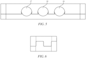
- the channels of the first half together with the channels of the second half form apertures 27, 28, 29, as shown in Fig. 5 .
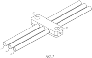
- the apertures are used to capture and secure tubes 37, 38, 39, as shown in Fig. 7 .
- Each aperture preferably supports a tube around the tube's entire circumference.
- the number and size of channels may be varied depending on the size and number of tubes to be supported.
- the tube clamp half may have 1, 2, 3, 4, 5, or 6 channels to support 1, 2, 3, 4, 5, or 6 tubes, respectively.
- the size and shape of each channel is designed to correspond to the size and shape of the tube to be supported.
- the channel has a circular profile, such that the channel of a first tube clamp half and the channel of a second tube clamp half together form a 1" diameter circular aperture supporting the entire circumference of the round tube.
- the channels may be various shapes and sizes, and may have predetermined shapes and sizes designed for the surface defining the aperture formed by the tube clamp to be in contact with the entire outer surface of the tube.
- the tube clamp halves are made of a flexible material such as nylon, and the channel shape is between a semi-circle and a full circle, as shown in Figs. 1 , 2 , and 3 .
- a tube clamp half to be secured on a tube by pushing the channel onto the tube so that the channel snaps onto the tube without sliding along the length of the tube.
- This permits easy installation of a tube clamp by securing one tube clamp half onto the tubes to be supported, then securing a second tube clamp half on the tubes while also engaging the corresponding male and female joints of two halves to form an assembled tube clamp as shown in Fig. 7 . Because each tube clamp half is secured in place on the tubes and engaged with each other using corresponding male and female joints, no fastener between the two halves is required.
- the disclosed tube clamp may be made of any solid material, such as plastic, metal, wood, or ceramic.
- the material preferably is flexible enough to permit securing the tube clamp to a tube by pushing the channel over a tube, but also rigid enough to support the tubes.
- the material also preferably will not cause wearing or cutting into the tubes.
- each tube clamp half has optional bolt holes 21, 22.
- a bolt or other fastener may be installed through the bolt holes 21, 22 to secure an assembled tube clamp to another object, such as a wall or equipment frame.
Landscapes
- Engineering & Computer Science (AREA)
- General Engineering & Computer Science (AREA)
- Mechanical Engineering (AREA)
- Architecture (AREA)
- Civil Engineering (AREA)
- Structural Engineering (AREA)
- Supports For Pipes And Cables (AREA)
Description
- The present application claims priority to
U.S. Provisional Patent Application No. 62/661,394, filed on April 23, 2018 - This invention relates in general to a device for supporting a tube or plurality of tubes. Such tubes include instrumentation tubing and piping, pneumatic tubing and piping, hydraulic tubing and piping, electrical conduit, electrical cabling, or other rigid tubing or cabling.
- Tubing often requires a supporting device to dampen vibration and keep individual tubes separated from each other. Prior tube support devices do not support multiple tubes, can move axially along the length of a tube, and/or do not support a tube around the full circumference not the tube.
- The document
US 6 783 101 B discloses a boiler tube clamp, for securing boiler tubes in an equal-spaced, parallel arrangement, including a pair of mating half-clamps having multiple opposed recesses sized to snugly cradle boiler tubes of a given diameter. The half-clamps are brought together around the boiler tubes and either welded or bolted together, thereby aligning the tubes in the desired arrangement. The bolts and/or clamps used to secure together the mating half-clamps are unaffected by downward abrasive action that typically occurs in boilers. For welded-together half-clamps, the welds are on top and bottom surfaces where they are shielded from abrasive action. For bolted-together half-clamps, the bolts are protected from abrasive action by recessing the bolt heads and retaining nuts. - The document
US 5 029 782 A discloses an anchor bracket assembly for at least two parallel pipes, produced of two identical bracket halves made of rigid plastic material. The bracket includes U-shaped, undercut pipe location pockets. The two bracket elements are installed over the pipes from opposite sides so that the pipes are retained in the locations by the radially protruding lugs. The two bracket elements are then axially pushed together so that their end profiles interlock in order to secure the assembly. - The invention provides a tube clamp half for a tube clamp according to claim 1.
- It is also provided tube clamp device comprising a first clamp half and a second clamp half according to the invention to support tubing, piping, conduit, or cabling. This device allows multiple tubes to be captured and supported around the circumference of each tube and keeps each tube isolated from one another. The tube clamp securely captures each tube to prevent each tube from being pulled out of the tube clamp. The tube clamp includes two halves, each with a channel for each tube to be supported. The channel is designed to allow each half to be independently secured to a tube. The first half and second half also have matching male and female joints to allow engagement of the first half with the second half. When the first half and second half are engaged together, the channel of the first half and the channel of the second half together form an aperture supporting the tube around its circumference. When the first half and second half are engaged on a tube, each half captures the tube and the other half, securing the tube and preventing the tube clamp from sliding axially along the length of the tube.
-
-
Fig. 1 shows an isometric view of one half of a tube clamp. -
Fig. 2 shows an isometric view of two halves of a tube clamp disassembled. -
Fig. 3 shows a front view of two halves of a tube clamp disassembled. -
Fig. 4 shows a side view of two halves of a tube clamp disassembled. -
Fig. 5 shows a front view of two halves of a tube clamp assembled. -
Fig. 6 shows a side view of two halves of a tube clamp assembled. -
Fig. 7 shows an isometric view of two halves of a tube clamp assembled and secured to tubing. - The following is a list of explanatory non-limiting examples. There is no intention to deviate from the plain and ordinary meaning of the terms below and the following list contains illustrative examples only that are intended to be consistent with the plain and ordinary meaning of the terms.
- Non-limiting examples of tubes for use with the disclosed tube clamps include instrumentation tubing and piping, pneumatic tubing and piping, hydraulic tubing and piping, electrical conduit, electrical cabling, or other rigid tubing or cabling. The tube clamps have particular utility for use with small diameter (less than 2") tubing installations commonly used in industrial and commercial applications. For example, the tube clamps may be used with tubes having a diameter of 118", 1/4", 1/2", 3/4", 1", 1 1/8", 1 1/4", 1 1/2", 1 3/4", or 2".
-
Fig. 1 shows an embodiment of one half of a tube clamp. The tube clamp half has a length dimension "L" and a width dimension "W." Along the length of the tube clamp half is atooth 11 and agap 12 parallel to thetooth 11. Thegap 12 is formed between thetooth 11 and anend tooth 13. On the side of thetooth 11 opposite from thegap 12 is anend gap 14. Thetooth 11 andgap 12 have the same width, and the height of thetooth 11 is the same as the depth of thegap 12. Theend tooth 13 and theend gap 14 similarly have the same width, and the height of theend tooth 13 is the same as the depth of theend gap 14. The tube clamp half is configured so that one tube half clamp may be engaged with another, identical tube clamp half rotated 180-degrees. Thetooth 11 andgap 12 serve as corresponding male and female joints, respectively, that are used to engage two identical tube clamp halves together, as shown inFigs. 2 ,4 , and6 . Thetooth 11 of each tube clamp half fits into thegap 12 of the other half, and theend tooth 13 of each tube clamp half fits into theend gap 14 of the other half. - In other embodiments, the two halves are not identical, with one half having a single tooth as a male joint and the other half having a corresponding single gap as a female joint for engagement of the two halves. Various other configurations are possible for permitting engagement of the two halves of the tube clamp.
-
Channels channels tooth 11 andgap 12. When the male joint of one half is engaged with the female joint of a second half to form an assembled tube clamp, the channels of the first half together with the channels of the secondhalf form apertures Fig. 5 . The apertures are used to capture and securetubes 37, 38, 39, as shown inFig. 7 . Each aperture preferably supports a tube around the tube's entire circumference. - The number and size of channels may be varied depending on the size and number of tubes to be supported. For example, the tube clamp half may have 1, 2, 3, 4, 5, or 6 channels to support 1, 2, 3, 4, 5, or 6 tubes, respectively. The size and shape of each channel is designed to correspond to the size and shape of the tube to be supported. For example, for a 1" round tube, the channel has a circular profile, such that the channel of a first tube clamp half and the channel of a second tube clamp half together form a 1" diameter circular aperture supporting the entire circumference of the round tube. The channels may be various shapes and sizes, and may have predetermined shapes and sizes designed for the surface defining the aperture formed by the tube clamp to be in contact with the entire outer surface of the tube.
- In some embodiments, the tube clamp halves are made of a flexible material such as nylon, and the channel shape is between a semi-circle and a full circle, as shown in
Figs. 1 ,2 , and3 . Using a somewhat flexible material and a channel shape between a semi-circle and a circle permits a tube clamp half to be secured on a tube by pushing the channel onto the tube so that the channel snaps onto the tube without sliding along the length of the tube. This permits easy installation of a tube clamp by securing one tube clamp half onto the tubes to be supported, then securing a second tube clamp half on the tubes while also engaging the corresponding male and female joints of two halves to form an assembled tube clamp as shown inFig. 7 . Because each tube clamp half is secured in place on the tubes and engaged with each other using corresponding male and female joints, no fastener between the two halves is required. - The disclosed tube clamp may be made of any solid material, such as plastic, metal, wood, or ceramic. The material preferably is flexible enough to permit securing the tube clamp to a tube by pushing the channel over a tube, but also rigid enough to support the tubes. The material also preferably will not cause wearing or cutting into the tubes.
- As shown in
Fig. 2 , each tube clamp half has optional bolt holes 21, 22. A bolt or other fastener may be installed through the bolt holes 21, 22 to secure an assembled tube clamp to another object, such as a wall or equipment frame.
Claims (8)
- A tube clamp half for a tube clamp comprising:a length (L) and a width (W),a tooth (11) and an end tooth (13) along said length,a gap (12) and an end gap (14) along said length, wherein said tooth (11) and said gap (12) have the same width, and the height of said tooth (11) is the same as the depth of said gap (12) and wherein said end tooth (13) and said end gap (14) have the same width, and the height of said end tooth (13) is the same as the depth of said end gap (14), anda plurality of first channels (17, 18, 19) across said width and cutting through said tooth (11), said end tooth (13), said gap (12), and said end gap (14) such that the tooth (11) and end tooth (13) each have two parallel edges that limit and define a shape greater than a semi-circle and less than a full-circle for each first channel of the plurality of first channels (17, 18, 19), said plurality of first channels (17, 18, 19) designed for the surface defining each first channel of said plurality of first channels (17, 18, 19) to be in contact with an outer surface of a tube of a plurality of tubes (37, 38, 39), wherein when at least one of said first channels is engaged with at least one of said tubes, said contact prevents said tube clamp half from sliding axially along said tube, andwherein the shape of each of the first channels (17, 18, 19) is symmetrical across a vertical plane that bisects, along their axial direction, each of the first channels (17, 18, 19) at a minimum height of the first channels (17, 18, 19);wherein said tube clamp half is adapted to be secured to each tube of the plurality of tubes (37, 38, 39) by the two parallel edges of both the tooth (11) and end tooth (13), andwherein said plurality of first channels (17, 18, 19) is configured to engage with a plurality of second channels (17, 18, 19) of a second tube clamp half to form a plurality of apertures (27, 28, 29).
- The tube clamp half of claim 1, wherein said tube clamp half may be secured to at least one of said tubes by pushing at least one of said first channels over at least one of said tubes.
- The tube clamp half of claim 1, wherein said tube clamp half is made of nylon.
- A tube clamp comprising:a first clamp half and a second clamp half, the first clamp half and the second clamp half according to any of claims 1 to 3,said first half comprising a plurality of first channels (17, 18, 19) and two male joints, the two male joints being formed by the tooth (11) and the end tooth (13),said second half comprising a plurality of second channels (17, 18, 19) and two female joints-corresponding to said male joints, the two female joints being formed by the gap (12) and the end gap (14),wherein when said male joints are engaged with said female joints, said plurality of first channels (17, 18, 19) and said plurality of second channels (17, 18, 19) form a plurality of apertures (27, 28, 29), and being used to capture and secure tubes (37, 38, 39),wherein said plurality of first channels (17, 18, 19) have a predetermined shape greater than a semi-circle and less than a full circle designed for the surface defining each first channel of the plurality of first channels (17, 18, 19) to be in contact with an outer surface of a tube of a plurality of tubes (37, 38, 39), wherein when at least one of said first channels is engaged with at least one of said tubes (37, 38, 39), said contact prevents said first half from sliding axially along said tube;wherein the predetermined shape of each of the first channels is symmetrical across a vertical plane that bisects, along their axial direction, each of the first channels at a minimum height of the first channels (17, 18, 19);wherein the plurality of first channels (17, 18, 19) cut through each male joint such that each male joint comprises two parallel edges that limit and define the shape of each first channel of said plurality of first channels (17, 18, 19); andwherein the first half is adapted to be secured to each tube of the plurality of tubes (37, 38, 39) by the two parallel edges of each male joint.
- The tube clamp of claim 4, wherein said first half and said second half are identical.
- The tube clamp of claim 4, wherein said plurality of first channels (17, 18, 19) and said plurality of second channels (17, 18, 19) are predetermined shapes designed for the surface defining said plurality of apertures (27, 28, 29) to be in contact with the entire outer surface of said plurality of tubes (37, 38, 39).
- The tube clamp of claim 4, wherein said first half may be secured to at least one of said plurality of tubes by pushing at least one of said first channels (17, 18, 19) over at least one of said tubes (37, 38, 39).
- The tube clamp of claim 4, wherein said tube clamp is made of nylon.
Applications Claiming Priority (2)
| Application Number | Priority Date | Filing Date | Title |
|---|---|---|---|
| US201862661394P | 2018-04-23 | 2018-04-23 | |
| PCT/US2019/028689 WO2019209806A1 (en) | 2018-04-23 | 2019-04-23 | Snap-on tube and pipe support clamp |
Publications (3)
| Publication Number | Publication Date |
|---|---|
| EP3784940A1 EP3784940A1 (en) | 2021-03-03 |
| EP3784940A4 EP3784940A4 (en) | 2022-01-12 |
| EP3784940B1 true EP3784940B1 (en) | 2024-12-04 |
Family
ID=68235925
Family Applications (1)
| Application Number | Title | Priority Date | Filing Date |
|---|---|---|---|
| EP19792112.5A Active EP3784940B1 (en) | 2018-04-23 | 2019-04-23 | Pipe support clamp |
Country Status (3)
| Country | Link |
|---|---|
| US (1) | US10865912B2 (en) |
| EP (1) | EP3784940B1 (en) |
| WO (1) | WO2019209806A1 (en) |
Families Citing this family (13)
| Publication number | Priority date | Publication date | Assignee | Title |
|---|---|---|---|---|
| WO2019116105A1 (en) * | 2017-12-12 | 2019-06-20 | Ppc Broadband Fiber Ltd. | Stackable brackets for microducts and cables |
| US10903633B2 (en) * | 2018-06-07 | 2021-01-26 | Panduit Corp. | Interlocking cable cleat |
| WO2020154385A1 (en) * | 2019-01-24 | 2020-07-30 | Steelcase Inc. | Display support system and method for the use thereof |
| US10830375B1 (en) * | 2019-05-08 | 2020-11-10 | Karma Automotive Llc | Flat electrical cable gripping tool |
| JP7339095B2 (en) * | 2019-09-24 | 2023-09-05 | ファナック株式会社 | striatum support device |
| CN111306367B (en) * | 2020-03-04 | 2024-07-26 | 宁波奥克斯电气股份有限公司 | A split type pipeline clamping and fixing device |
| USD988859S1 (en) * | 2020-04-24 | 2023-06-13 | T&T Tools International Llc | Modular clamp block for tubing |
| USD918703S1 (en) * | 2020-07-18 | 2021-05-11 | BYM Industrial Products Co., Ltd | Cable clamp |
| WO2022113016A1 (en) * | 2020-11-30 | 2022-06-02 | Fi.Mo.Tec. S.P.A. | Saddle of an improved type for supporting elongated bodies |
| USD997701S1 (en) * | 2021-09-20 | 2023-09-05 | Edward Barr | Clamp for tubes, hoses, pipes or cables including top, middle, base and connector portions |
| US11746929B2 (en) | 2021-10-12 | 2023-09-05 | Sartorius Stedim North America Inc. | Tube organizer assembly |
| US12010811B1 (en) * | 2023-01-06 | 2024-06-11 | Quanta Computer Inc. | Cable clip assembly and method for computing system |
| USD1065964S1 (en) * | 2023-01-31 | 2025-03-11 | Inaba Denki Sangyo Co., Ltd. | Piping support tool |
Family Cites Families (25)
| Publication number | Priority date | Publication date | Assignee | Title |
|---|---|---|---|---|
| US3286767A (en) | 1964-10-01 | 1966-11-22 | Babcock & Wilcox Co | Tube support arrangement |
| US3367683A (en) * | 1965-08-27 | 1968-02-06 | Anchor Coupling Co Inc | Hose coupling |
| IT1086606B (en) * | 1976-11-29 | 1985-05-28 | Althouse Victor E | SILICONIC RUBBER CLOSING ELEMENT AND PROCEDURE TO APPLY IT |
| US4557024A (en) | 1984-02-06 | 1985-12-10 | 501 Evelyn Investments Ltd. | Clamp for hose, tubing, or the like |
| EP0351524B1 (en) * | 1988-07-18 | 1991-12-27 | Egli, Fischer & Co. AG | Clamp device |
| DE3913360C1 (en) * | 1989-04-22 | 1990-09-13 | Fa. A. Raymond, 7850 Loerrach, De | |
| US5083372A (en) | 1991-03-11 | 1992-01-28 | Power & Industrial Services Corp. | Method and apparatus for aligning and clamping a series of tubes in parallel |
| US5136985A (en) | 1991-09-12 | 1992-08-11 | Deltak Corporation | Boiler tube support |
| US5992802A (en) * | 1997-05-14 | 1999-11-30 | Campbell Design Systems | Cable support |
| US6007029A (en) | 1998-06-03 | 1999-12-28 | Astech, Inc. | Boiler tube alignment link system |
| US6783101B2 (en) | 2000-07-26 | 2004-08-31 | Brook H. Knotts | Clamp for securing multiple, spaced-apart tubes |
| GB2367695B (en) * | 2000-09-27 | 2004-09-08 | Alan Dick & Company Ltd | Cable clamp |
| US6561466B1 (en) * | 2002-02-20 | 2003-05-13 | Mitchell W. Myers | Interchangeable hose, cable, and conduit support mechanism |
| BRPI0604028B1 (en) * | 2006-09-04 | 2019-12-24 | Embraco Ind De Compressores E Solucoes Em Refrigeracao Ltda | clamp for tubular connections in small refrigeration systems |
| WO2008119112A1 (en) * | 2007-03-30 | 2008-10-09 | Sun Chan | Conduit joining apparatus |
| US8342474B2 (en) * | 2008-03-07 | 2013-01-01 | The Gates Corporation | Modular support, assemblies, methods and systems |
| US8702044B2 (en) * | 2009-02-04 | 2014-04-22 | The Gates Corporation | Conduit bracketry, systems and methods |
| EP2253873A1 (en) | 2009-05-20 | 2010-11-24 | Walter Stauffenberg Gmbh & Co. Kg | Pipe clip |
| US9038968B2 (en) * | 2009-06-09 | 2015-05-26 | John HENNON | Attachable grommets for hanging pipes |
| FR2974877A1 (en) * | 2011-05-03 | 2012-11-09 | Airbus Operations Sas | DEVICE FOR FIXING PIPES OF AN AIRCRAFT |
| WO2014036325A2 (en) | 2012-08-30 | 2014-03-06 | C.R. Bard, Inc. | Tubing clamp |
| US20180058611A1 (en) * | 2016-08-25 | 2018-03-01 | Caterpillar Sarl | Clamping assembly |
| DE102017207513A1 (en) * | 2017-05-04 | 2018-11-08 | Hamm Ag | Fastening device for hoses |
| US10800540B2 (en) * | 2017-08-03 | 2020-10-13 | The Boeing Company | Transport element clamp system |
| DE102018103666B4 (en) * | 2018-02-19 | 2021-07-01 | PSZ electronic GmbH | Fastening clip element for fastening and arranging pipe, hose or sheathed cables |
-
2019
- 2019-04-23 EP EP19792112.5A patent/EP3784940B1/en active Active
- 2019-04-23 WO PCT/US2019/028689 patent/WO2019209806A1/en unknown
- 2019-04-23 US US16/391,662 patent/US10865912B2/en active Active
Also Published As
| Publication number | Publication date |
|---|---|
| US20190323632A1 (en) | 2019-10-24 |
| US10865912B2 (en) | 2020-12-15 |
| EP3784940A1 (en) | 2021-03-03 |
| WO2019209806A1 (en) | 2019-10-31 |
Similar Documents
| Publication | Publication Date | Title |
|---|---|---|
| EP3784940B1 (en) | Pipe support clamp | |
| US7384076B2 (en) | Pipe ring apparatus and method | |
| AU2019200142B2 (en) | Split ring coupling | |
| US10578234B2 (en) | Coupling having arcuate stiffness ribs | |
| US8342474B2 (en) | Modular support, assemblies, methods and systems | |
| KR101953728B1 (en) | System for sealingly holding cables which extend through an opening | |
| US6454232B1 (en) | Stiffener apparatus for stabilizing a hanger rod | |
| CA2749222A1 (en) | Mechanical pipe coupling having spacers | |
| US20070090646A1 (en) | Coupling having angularly oriented cavity | |
| SE421826B (en) | WELDING DEVICE FOR A MUFFROR COMBINATION | |
| EP3458761B1 (en) | Fitting having tabbed retainer and observation apertures | |
| KR101508659B1 (en) | A device for tightening joint of pipe | |
| US6991198B1 (en) | Apparatus for stiffening a hanger rod | |
| US6783104B1 (en) | Deformable clamp employed to stiffen hanger rod | |
| KR20180030958A (en) | Pipe coupler | |
| KR200478598Y1 (en) | Space Preservation Unit For Pipe | |
| JP5057593B2 (en) | Support device for non-average forces in pipes | |
| JP6649544B2 (en) | Piping support | |
| CA2732048C (en) | Split joint restraint device with dual pipe size capability | |
| US12134499B1 (en) | Skid apparatus, system and method | |
| GB2536971A (en) | A coupling device for use in connecting trunking sections | |
| EP3021028B1 (en) | Pipe clamp assembly with stiffening element | |
| JP2019128003A (en) | Piping support tool | |
| US20220268380A1 (en) | Pipe length and related methods of pipe connection | |
| JPH0583575U (en) | Pipe connection device |
Legal Events
| Date | Code | Title | Description |
|---|---|---|---|
| STAA | Information on the status of an ep patent application or granted ep patent |
Free format text: STATUS: THE INTERNATIONAL PUBLICATION HAS BEEN MADE |
|
| STAA | Information on the status of an ep patent application or granted ep patent |
Free format text: STATUS: THE INTERNATIONAL PUBLICATION HAS BEEN MADE |
|
| PUAI | Public reference made under article 153(3) epc to a published international application that has entered the european phase |
Free format text: ORIGINAL CODE: 0009012 |
|
| STAA | Information on the status of an ep patent application or granted ep patent |
Free format text: STATUS: REQUEST FOR EXAMINATION WAS MADE |
|
| 17P | Request for examination filed |
Effective date: 20201104 |
|
| AK | Designated contracting states |
Kind code of ref document: A1 Designated state(s): AL AT BE BG CH CY CZ DE DK EE ES FI FR GB GR HR HU IE IS IT LI LT LU LV MC MK MT NL NO PL PT RO RS SE SI SK SM TR |
|
| AX | Request for extension of the european patent |
Extension state: BA ME |
|
| DAV | Request for validation of the european patent (deleted) | ||
| DAX | Request for extension of the european patent (deleted) | ||
| A4 | Supplementary search report drawn up and despatched |
Effective date: 20211213 |
|
| RIC1 | Information provided on ipc code assigned before grant |
Ipc: F16L 3/13 20060101ALI20211207BHEP Ipc: H02G 3/32 20060101ALI20211207BHEP Ipc: F16L 3/223 20060101ALI20211207BHEP Ipc: F16L 3/137 20060101ALI20211207BHEP Ipc: F16L 3/12 20060101ALI20211207BHEP Ipc: F16L 3/08 20060101ALI20211207BHEP Ipc: F16L 3/10 20060101AFI20211207BHEP |
|
| STAA | Information on the status of an ep patent application or granted ep patent |
Free format text: STATUS: EXAMINATION IS IN PROGRESS |
|
| 17Q | First examination report despatched |
Effective date: 20231103 |
|
| GRAP | Despatch of communication of intention to grant a patent |
Free format text: ORIGINAL CODE: EPIDOSNIGR1 |
|
| STAA | Information on the status of an ep patent application or granted ep patent |
Free format text: STATUS: GRANT OF PATENT IS INTENDED |
|
| INTG | Intention to grant announced |
Effective date: 20240624 |
|
| GRAS | Grant fee paid |
Free format text: ORIGINAL CODE: EPIDOSNIGR3 |
|
| GRAA | (expected) grant |
Free format text: ORIGINAL CODE: 0009210 |
|
| STAA | Information on the status of an ep patent application or granted ep patent |
Free format text: STATUS: THE PATENT HAS BEEN GRANTED |
|
| AK | Designated contracting states |
Kind code of ref document: B1 Designated state(s): AL AT BE BG CH CY CZ DE DK EE ES FI FR GB GR HR HU IE IS IT LI LT LU LV MC MK MT NL NO PL PT RO RS SE SI SK SM TR |
|
| REG | Reference to a national code |
Ref country code: CH Ref legal event code: EP |
|
| REG | Reference to a national code |
Ref country code: DE Ref legal event code: R096 Ref document number: 602019063034 Country of ref document: DE |
|
| REG | Reference to a national code |
Ref country code: IE Ref legal event code: FG4D |
|
| REG | Reference to a national code |
Ref country code: LT Ref legal event code: MG9D |
|
| REG | Reference to a national code |
Ref country code: NL Ref legal event code: MP Effective date: 20241204 |
|
| PG25 | Lapsed in a contracting state [announced via postgrant information from national office to epo] |
Ref country code: HR Free format text: LAPSE BECAUSE OF FAILURE TO SUBMIT A TRANSLATION OF THE DESCRIPTION OR TO PAY THE FEE WITHIN THE PRESCRIBED TIME-LIMIT Effective date: 20241204 |
|
| PG25 | Lapsed in a contracting state [announced via postgrant information from national office to epo] |
Ref country code: FI Free format text: LAPSE BECAUSE OF FAILURE TO SUBMIT A TRANSLATION OF THE DESCRIPTION OR TO PAY THE FEE WITHIN THE PRESCRIBED TIME-LIMIT Effective date: 20241204 |
|
| PG25 | Lapsed in a contracting state [announced via postgrant information from national office to epo] |
Ref country code: BG Free format text: LAPSE BECAUSE OF FAILURE TO SUBMIT A TRANSLATION OF THE DESCRIPTION OR TO PAY THE FEE WITHIN THE PRESCRIBED TIME-LIMIT Effective date: 20241204 |
|
| PG25 | Lapsed in a contracting state [announced via postgrant information from national office to epo] |
Ref country code: ES Free format text: LAPSE BECAUSE OF FAILURE TO SUBMIT A TRANSLATION OF THE DESCRIPTION OR TO PAY THE FEE WITHIN THE PRESCRIBED TIME-LIMIT Effective date: 20241204 |
|
| PG25 | Lapsed in a contracting state [announced via postgrant information from national office to epo] |
Ref country code: NO Free format text: LAPSE BECAUSE OF FAILURE TO SUBMIT A TRANSLATION OF THE DESCRIPTION OR TO PAY THE FEE WITHIN THE PRESCRIBED TIME-LIMIT Effective date: 20250304 |
|
| PG25 | Lapsed in a contracting state [announced via postgrant information from national office to epo] |
Ref country code: LV Free format text: LAPSE BECAUSE OF FAILURE TO SUBMIT A TRANSLATION OF THE DESCRIPTION OR TO PAY THE FEE WITHIN THE PRESCRIBED TIME-LIMIT Effective date: 20241204 Ref country code: GR Free format text: LAPSE BECAUSE OF FAILURE TO SUBMIT A TRANSLATION OF THE DESCRIPTION OR TO PAY THE FEE WITHIN THE PRESCRIBED TIME-LIMIT Effective date: 20250305 |
|
| PG25 | Lapsed in a contracting state [announced via postgrant information from national office to epo] |
Ref country code: RS Free format text: LAPSE BECAUSE OF FAILURE TO SUBMIT A TRANSLATION OF THE DESCRIPTION OR TO PAY THE FEE WITHIN THE PRESCRIBED TIME-LIMIT Effective date: 20250304 |
|
| PG25 | Lapsed in a contracting state [announced via postgrant information from national office to epo] |
Ref country code: NL Free format text: LAPSE BECAUSE OF FAILURE TO SUBMIT A TRANSLATION OF THE DESCRIPTION OR TO PAY THE FEE WITHIN THE PRESCRIBED TIME-LIMIT Effective date: 20241204 |
|
| REG | Reference to a national code |
Ref country code: AT Ref legal event code: MK05 Ref document number: 1748498 Country of ref document: AT Kind code of ref document: T Effective date: 20241204 |
|
| PG25 | Lapsed in a contracting state [announced via postgrant information from national office to epo] |
Ref country code: SM Free format text: LAPSE BECAUSE OF FAILURE TO SUBMIT A TRANSLATION OF THE DESCRIPTION OR TO PAY THE FEE WITHIN THE PRESCRIBED TIME-LIMIT Effective date: 20241204 |
|
| PG25 | Lapsed in a contracting state [announced via postgrant information from national office to epo] |
Ref country code: PL Free format text: LAPSE BECAUSE OF FAILURE TO SUBMIT A TRANSLATION OF THE DESCRIPTION OR TO PAY THE FEE WITHIN THE PRESCRIBED TIME-LIMIT Effective date: 20241204 |
|
| PGFP | Annual fee paid to national office [announced via postgrant information from national office to epo] |
Ref country code: DE Payment date: 20250507 Year of fee payment: 7 |