EP3784892B1 - Verfahren zum betreiben eines verbrennungsmotors - Google Patents
Verfahren zum betreiben eines verbrennungsmotors Download PDFInfo
- Publication number
- EP3784892B1 EP3784892B1 EP19717869.2A EP19717869A EP3784892B1 EP 3784892 B1 EP3784892 B1 EP 3784892B1 EP 19717869 A EP19717869 A EP 19717869A EP 3784892 B1 EP3784892 B1 EP 3784892B1
- Authority
- EP
- European Patent Office
- Prior art keywords
- actuator
- variation
- relative
- combustion engine
- torque
- Prior art date
- Legal status (The legal status is an assumption and is not a legal conclusion. Google has not performed a legal analysis and makes no representation as to the accuracy of the status listed.)
- Active
Links
Images


Classifications
-
- F—MECHANICAL ENGINEERING; LIGHTING; HEATING; WEAPONS; BLASTING
- F02—COMBUSTION ENGINES; HOT-GAS OR COMBUSTION-PRODUCT ENGINE PLANTS
- F02D—CONTROLLING COMBUSTION ENGINES
- F02D41/00—Electrical control of supply of combustible mixture or its constituents
- F02D41/0002—Controlling intake air
-
- F—MECHANICAL ENGINEERING; LIGHTING; HEATING; WEAPONS; BLASTING
- F02—COMBUSTION ENGINES; HOT-GAS OR COMBUSTION-PRODUCT ENGINE PLANTS
- F02B—INTERNAL-COMBUSTION PISTON ENGINES; COMBUSTION ENGINES IN GENERAL
- F02B27/00—Use of kinetic or wave energy of charge in induction systems, or of combustion residues in exhaust systems, for improving quantity of charge or for increasing removal of combustion residues
- F02B27/02—Use of kinetic or wave energy of charge in induction systems, or of combustion residues in exhaust systems, for improving quantity of charge or for increasing removal of combustion residues the systems having variable, i.e. adjustable, cross-sectional areas, chambers of variable volume, or like variable means
- F02B27/0294—Actuators or controllers therefor; Diagnosis; Calibration
-
- F—MECHANICAL ENGINEERING; LIGHTING; HEATING; WEAPONS; BLASTING
- F02—COMBUSTION ENGINES; HOT-GAS OR COMBUSTION-PRODUCT ENGINE PLANTS
- F02D—CONTROLLING COMBUSTION ENGINES
- F02D41/00—Electrical control of supply of combustible mixture or its constituents
- F02D41/02—Circuit arrangements for generating control signals
- F02D41/14—Introducing closed-loop corrections
- F02D41/1401—Introducing closed-loop corrections characterised by the control or regulation method
- F02D41/1406—Introducing closed-loop corrections characterised by the control or regulation method with use of a optimisation method, e.g. iteration
-
- F—MECHANICAL ENGINEERING; LIGHTING; HEATING; WEAPONS; BLASTING
- F02—COMBUSTION ENGINES; HOT-GAS OR COMBUSTION-PRODUCT ENGINE PLANTS
- F02B—INTERNAL-COMBUSTION PISTON ENGINES; COMBUSTION ENGINES IN GENERAL
- F02B29/00—Engines characterised by provision for charging or scavenging not provided for in groups F02B25/00, F02B27/00 or F02B33/00 - F02B39/00; Details thereof
- F02B29/02—Other fluid-dynamic features of induction systems for improving quantity of charge
-
- F—MECHANICAL ENGINEERING; LIGHTING; HEATING; WEAPONS; BLASTING
- F02—COMBUSTION ENGINES; HOT-GAS OR COMBUSTION-PRODUCT ENGINE PLANTS
- F02B—INTERNAL-COMBUSTION PISTON ENGINES; COMBUSTION ENGINES IN GENERAL
- F02B29/00—Engines characterised by provision for charging or scavenging not provided for in groups F02B25/00, F02B27/00 or F02B33/00 - F02B39/00; Details thereof
- F02B29/08—Modifying distribution valve timing for charging purposes
- F02B29/083—Cyclically operated valves disposed upstream of the cylinder intake valve, controlled by external means
-
- F—MECHANICAL ENGINEERING; LIGHTING; HEATING; WEAPONS; BLASTING
- F02—COMBUSTION ENGINES; HOT-GAS OR COMBUSTION-PRODUCT ENGINE PLANTS
- F02D—CONTROLLING COMBUSTION ENGINES
- F02D11/00—Arrangements for, or adaptations to, non-automatic engine control initiation means, e.g. operator initiated
- F02D11/06—Arrangements for, or adaptations to, non-automatic engine control initiation means, e.g. operator initiated characterised by non-mechanical control linkages, e.g. fluid control linkages or by control linkages with power drive or assistance
- F02D11/10—Arrangements for, or adaptations to, non-automatic engine control initiation means, e.g. operator initiated characterised by non-mechanical control linkages, e.g. fluid control linkages or by control linkages with power drive or assistance of the electric type
- F02D11/105—Arrangements for, or adaptations to, non-automatic engine control initiation means, e.g. operator initiated characterised by non-mechanical control linkages, e.g. fluid control linkages or by control linkages with power drive or assistance of the electric type characterised by the function converting demand to actuation, e.g. a map indicating relations between an accelerator pedal position and throttle valve opening or target engine torque
-
- F—MECHANICAL ENGINEERING; LIGHTING; HEATING; WEAPONS; BLASTING
- F02—COMBUSTION ENGINES; HOT-GAS OR COMBUSTION-PRODUCT ENGINE PLANTS
- F02D—CONTROLLING COMBUSTION ENGINES
- F02D41/00—Electrical control of supply of combustible mixture or its constituents
- F02D41/0002—Controlling intake air
- F02D2041/0017—Controlling intake air by simultaneous control of throttle and exhaust gas recirculation
-
- F—MECHANICAL ENGINEERING; LIGHTING; HEATING; WEAPONS; BLASTING
- F02—COMBUSTION ENGINES; HOT-GAS OR COMBUSTION-PRODUCT ENGINE PLANTS
- F02D—CONTROLLING COMBUSTION ENGINES
- F02D41/00—Electrical control of supply of combustible mixture or its constituents
- F02D41/0002—Controlling intake air
- F02D2041/002—Controlling intake air by simultaneous control of throttle and variable valve actuation
-
- F—MECHANICAL ENGINEERING; LIGHTING; HEATING; WEAPONS; BLASTING
- F02—COMBUSTION ENGINES; HOT-GAS OR COMBUSTION-PRODUCT ENGINE PLANTS
- F02D—CONTROLLING COMBUSTION ENGINES
- F02D41/00—Electrical control of supply of combustible mixture or its constituents
- F02D41/02—Circuit arrangements for generating control signals
- F02D41/14—Introducing closed-loop corrections
- F02D41/1401—Introducing closed-loop corrections characterised by the control or regulation method
- F02D2041/1413—Controller structures or design
-
- Y—GENERAL TAGGING OF NEW TECHNOLOGICAL DEVELOPMENTS; GENERAL TAGGING OF CROSS-SECTIONAL TECHNOLOGIES SPANNING OVER SEVERAL SECTIONS OF THE IPC; TECHNICAL SUBJECTS COVERED BY FORMER USPC CROSS-REFERENCE ART COLLECTIONS [XRACs] AND DIGESTS
- Y02—TECHNOLOGIES OR APPLICATIONS FOR MITIGATION OR ADAPTATION AGAINST CLIMATE CHANGE
- Y02T—CLIMATE CHANGE MITIGATION TECHNOLOGIES RELATED TO TRANSPORTATION
- Y02T10/00—Road transport of goods or passengers
- Y02T10/10—Internal combustion engine [ICE] based vehicles
- Y02T10/12—Improving ICE efficiencies
-
- Y—GENERAL TAGGING OF NEW TECHNOLOGICAL DEVELOPMENTS; GENERAL TAGGING OF CROSS-SECTIONAL TECHNOLOGIES SPANNING OVER SEVERAL SECTIONS OF THE IPC; TECHNICAL SUBJECTS COVERED BY FORMER USPC CROSS-REFERENCE ART COLLECTIONS [XRACs] AND DIGESTS
- Y02—TECHNOLOGIES OR APPLICATIONS FOR MITIGATION OR ADAPTATION AGAINST CLIMATE CHANGE
- Y02T—CLIMATE CHANGE MITIGATION TECHNOLOGIES RELATED TO TRANSPORTATION
- Y02T10/00—Road transport of goods or passengers
- Y02T10/10—Internal combustion engine [ICE] based vehicles
- Y02T10/40—Engine management systems
Definitions
- the present invention relates to a method for operating an internal combustion engine, in particular of a motor vehicle.
- Internal combustion engines are used in mobile applications, particularly in road vehicles, but also in aircraft and watercraft, as well as in stationary applications for drive units or to generate energy (combined heat and power plants).
- An internal combustion engine usually comprises an engine block with one or more cylinders with pistons with adjustable stroke (so-called piston engines or reciprocating piston engines).
- the gas exchange processes in the cylinders or in the combustion chamber are controlled by inlet and outlet valves (gas exchange valves).
- a fresh air system is provided to supply fresh air to the cylinders.
- a fresh air system typically comprises a fresh air duct, a fresh air distributor, from which individual fresh air pipes lead to each cylinder.
- the exhaust system is constructed in a similar way; the exhaust gases from the individual cylinders are collected via an exhaust manifold and expelled via an exhaust duct.
- the fresh air system and exhaust system are closely interlinked mechanically and fluidically.
- Part of the exhaust gas energy is used via exhaust turbochargers to compress the fresh air supplied, the exhaust gas flows themselves can be diverted directly into the fresh air flow via high-pressure exhaust gas recirculation, and in the same way the exhaust gas flows subjected to exhaust gas aftertreatment (e.g. exhaust gas catalyst, soot filter, nitrogen oxide reduction) can be fed into the fresh air (low-pressure exhaust gas recirculation).
- exhaust gas aftertreatment e.g. exhaust gas catalyst, soot filter, nitrogen oxide reduction
- pressure pulsations occur in both the fresh air system and the exhaust system. These are caused by the combustion cycles during cyclical operation of the reciprocating piston engine with the typical phases (e.g. 4-stroke) intake, compression, combustion and exhaust in the cylinder. This also includes cyclical short circuits of the combustion chamber to the fresh air and exhaust system during intake and exhaust and the associated gas mass transport and pressure equalization between the short-circuited sections.
- Various peripheral actuators are provided to control the exhaust gas and fresh air flows.
- this refers in particular to flaps and valves such as the throttle valve, VTG blade travel adjustment (for turbochargers with adjustable turbine geometry), ATL wastegate valves, high-pressure exhaust gas recirculation valves and low-pressure exhaust gas recirculation valves.
- flaps and valves such as the throttle valve, VTG blade travel adjustment (for turbochargers with adjustable turbine geometry), ATL wastegate valves, high-pressure exhaust gas recirculation valves and low-pressure exhaust gas recirculation valves.
- the VTG blade travel adjustment is used, for example, to adjust a boost pressure
- the throttle valve adjustment regulates the intake manifold pressure and thus the amount of gas sucked in
- an exhaust gas recirculation valve sets a recirculated EGR mass flow and thus changes the quality (composition) and quantity (pressure, temperature) of the gas mass supplied to the combustion chamber (cylinder).
- the gas mass taken in (described by pressure, temperature and composition) has a decisive influence on the quality of the combustion process in terms of consumption and the resulting emissions.
- the pressure level in the intake manifold and exhaust manifold is adjusted via the throttle valve and the VTG position. These two pressures directly influence the resulting charge exchange losses of the combustion engine and thus also the consumption.
- exhaust gas recirculation can be adjusted both internally via the charge exchange control elements (fresh and exhaust valves) and supplemented by exhaust gas recirculation valves in the engine periphery.
- the pressure pulsations mentioned above are caused by the working cycle of the combustion engine and continue in the periphery of the engine. This means that the pressures and mass flows also vary in the peripheral areas of the exhaust system and the fresh air system over the working cycle of all cylinders. These pulsations change according to the operating conditions of the combustion engine.
- the actuators are set to be quasi stationary in relation to the pulsations and with regard to a specific operating condition, i.e. they do not change in relation to the pressure and volume pulsations.
- the fresh air supply is to be optimized not only depending on the operating state, but also synchronously with the combustion cycle. In principle, this makes it possible to Fresh air supply not only globally, but also individually for each cylinder.
- the fresh air system has an additional valve that is arranged in a fresh air duct and is operated in such a way that opening phases, in which the additional valve opens the fresh air duct, and closing phases, in which the additional valve closes the fresh air duct, alternate, with the opening phases being varied depending on the current operating state of the internal combustion engine in order to adapt these opening phases to the current operating state.
- the opening duration is adapted by varying the closing time of this opening phase depending on its phase position to the crankshaft angle.
- the object of the present invention is to provide a method for operating an internal combustion engine in which the above-mentioned disadvantages are at least partially overcome.
- a further object can be seen in providing an internal combustion engine and a vehicle which are suitable for being operated according to such a method.
- the method according to the invention is characterized in that, for at least one of the peripheral actuators (see above), in addition to a temporally average - hereinafter referred to as global - actuator position, which is set with regard to a detected operating state of the internal combustion engine, a temporally relative actuator variation is also determined and the global actuator position is changed by this relative actuator variation.
- the relative actuator variation takes place synchronously with the combustion cycle in such a way that a change in the pressure pulsation caused by the actuator variation, in particular in the fresh air system and/or in the exhaust system, a gas quantity or desired gas quantity and/or composition in the cylinder, in the fresh air system and/or in the exhaust system is set to minimize consumption and/or emissions.
- it is about changing the pressure pulsations by means of a relative position control synchronized with the combustion cycle by an operating point-dependent mean (global) position of the actuators on the periphery of the engine in order to raise the target parameters of the combustion process (lower consumption, lower emissions) to an overall improved level, as the processes can be improved, adapted and equalized for each cylinder.
- combustion-cycle-synchronous control of the actuators also allows equalization and optimization of the work processes in the individual cylinders (particularly with regard to the amount of gas sucked in and its composition).
- optimization can be achieved by controlling the exhaust gas recirculation valves synchronously with the combustion cycle (high-pressure exhaust gas recirculation, internal exhaust gas recirculation via the gas exchange valves and low-pressure exhaust gas recirculation) by generating pressure gradients between the exhaust manifold and intake manifold as required.
- the combination of the middle position of an actuator (global actuator position) and a relative curve (relative actuator variation) enables the continued use of existing engine control methods and their addition to the combustion engine-synchronous control, which can optionally be dispensed with if necessary.
- the respective peripheral actuator is designed as a throttle valve, a high-pressure exhaust gas recirculation valve, a low-pressure exhaust gas recirculation valve, a VTG adjustment and/or an exhaust flap.
- These actuators significantly influence the pressure and composition of the individual gas flows in the fresh air system and in the exhaust system.
- the coupling of these systems can be optimized using one or more of these actuators.
- the relative actuator variation comprises a relative target curve that can be described by a control signal impressed in synchronism with the combustion cycle, in particular a torque curve of the actuator impressed in synchronism with the combustion cycle.
- This can be an adjustment torque or an adjustment torque curve.
- This design is particularly advantageous for electrically or electromotorically controlled actuators.
- An adjustment torque synchronized with the combustion cycle or a relative torque curve simplifies the energetic evaluation of the effort required for adjustment without having to make compromises with regard to the quality (setting accuracy) of the resulting position changes. This is because large differences in energy expenditure can occur during braking and acceleration phases with small position differences.
- a relative additional adjustment torque is imposed on the classic mean target position of the actuator (global actuator position) in order to subject the actuator to a further relative acceleration and/or deceleration, which leads to a speed variation and thus to a change in the position of the actuator.
- This allows the global setting of the actuator and the relative variation of the actuator to be superimposed particularly elegantly in terms of control technology.
- the relative actuator variation is determined taking into account at least one of the following criteria: costs of the actuator variation, benefits of the actuator variation, limit torque and/or the power consumption of an actuating device that carries out the actuator variation.
- costs of the actuator variation are not only the additional costs of an additional or additionally upgraded actuating device, but also the energy required for the additional relative actuator variation.
- the costs and benefits of the actuator variation can be weighed against each other in standardized cost functions, for example. Such functions also make it possible to take into account "price changes” that occur over the service life of a combustion engine or a vehicle, thus adapting the process to changing conditions. "Price” or “cost changes” can be caused, for example, by changes in emissions or consumption regulations.
- the limit torque and/or current consumption of an actuator that carries out the actuator variation must of course also be taken into account in order to be able to adequately take into account the lifetime-relevant boundary conditions.
- a further developed method in which the relative actuator variation takes place taking into account a current angular position of the combustion engine, allows a particularly simple synchronization with the combustion cycle, since the crankshaft position or the camshaft position represents a recorded and always available process variable from which each cylinder position can be derived and which is closely related to the global and local pressure pulsations to be changed.
- a relative actuator variation and/or a relative actuator variation curve can be called up from a memory for each angular position
- the desired actuator variations or actuator variation curves can be used that were obtained in simulations, tests or calculations and are thus available via a memory, for example an engine control unit.
- the term "callable” should not be restricted in this context to the extent that only those actuator variations or actuator variation curves that are already permanently stored in the memory can be used, but the term callable should also include those actuator variations or actuator variation curves that are determined, for example, during real-time operation in a suitable engine control unit depending on input signals from a wide variety of sensors, from stored or calculated characteristic maps and operating points and are determined using suitable algorithms.
- Typical sensor signals can be, for example, pressures and temperatures at different points in the fresh air system and/or in the exhaust system as well as temperatures in the cooling system or in the fuel system or in the oil circuit as well as other exhaust gas and consumption-related signal variables.
- the following steps are carried out: Determining a current angular position of the combustion engine, reading a relative actuator variation and/or a relative actuator variation curve from the memory and overlaying the global actuator position with the relative actuator variation and/or the relative actuator variation curve depending on the current angular position.
- This method allows a particularly elegant determination and implementation of the relative actuator variation in conjunction with the global actuator position.
- the overlay step includes the following: Converting the relative actuator variation and/or the relative actuator variation curve into a torque change, comparing the global actuator position with an actual position of the actuator and determining an average torque specification, adding the torque change to the average torque specification and determining a resulting torque, determining a control signal from the resulting torque and transmitting the control signal to the actuator or an actuating device which adjusts the actuator.
- This method includes a feedback (control loop) of the actuator position with an actual position of the actuator (which may be filtered to compensate for fluctuations caused by pulsation), so that not only a global target actuator position is used to determine a resulting torque, but a global actuator position corrected for the actual position serves as a basis.
- the control signal determined in this way from the resulting torque ensures the necessary relative actuator variation with minimal energy expenditure and thus at minimal "costs".
- An internal combustion engine that is provided with a controller that is designed to carry out the method according to the invention allows further consumption and emissions optimization without fundamental changes to the engine system being necessary.
- the optimizations can also be carried out in a scalable manner by initially providing or equipping only one or a few essential actuators for a relative actuator variation, e.g. starting with the throttle valve. It is also possible to keep open the possibility of providing further actuators for the relative actuator variation via the controller in order to make additional actuator variations feasible for future emissions regulations.
- a vehicle with an internal combustion engine designed to carry out the method according to the invention can be operated with reduced emissions or with reduced fuel consumption.
- FIG. 1 shows a vehicle 100 with an internal combustion engine 1, which has a fresh air system 2, an exhaust system 3 and one or more cylinders 4, to which fresh air is supplied via one or more intake valves 5 and from which exhaust gas is discharged via one or more exhaust valves 6.
- the intake fresh air flow first passes through an air filter 7, is compressed in a compressor part of an exhaust turbocharger 8.
- the supply of fresh air is regulated via the throttle valve arrangement 9, which forms one of several peripheral actuators, passes through a charge air cooler 10 and flows through an intake valve 5 into the cylinder 4.
- the exhaust gas flow is expelled from the cylinder 4 through an exhaust valve 6, drives the turbine of the exhaust gas turbocharger 8, which is provided with a variable turbine geometry and thus with a VTG adjustment 11, which forms another peripheral actuator.
- the exhaust gas flow then passes through an exhaust gas treatment system 12 (catalyst NSC, DPF, etc.) and leaves the exhaust system 3 through an exhaust flap arrangement 13.
- Fresh air system 2 and exhaust system 3 are coupled, on the one hand, primarily via the cylinders 4 to the intake and exhaust valves 5 and 6 and, secondarily, via a high-pressure exhaust gas recirculation 14 to a high-pressure exhaust gas recirculation valve 15 and a low-pressure exhaust gas recirculation 16 to a low-pressure exhaust gas recirculation valve 17.
- the exhaust flap arrangement 13, the high-pressure exhaust gas recirculation valve 15 and the low-pressure exhaust gas recirculation valve 17 as well as the VTG adjustment 11 also form peripheral actuators that can be adjusted, controlled or regulated via electrically controllable actuating devices.
- Fig. 2 shows a schematic representation of an embodiment of a method according to the invention, which is carried out in connection with the throttle valve arrangement.
- sensors are required, which are also in Fig. 1 shown or sketched. These include a throttle position sensor 18 and a crankshaft position sensor 19.
- additional sensors can also be provided, which can be used, for example, to control the VTG adjustment 11 of the high-pressure exhaust gas recirculation 14, the low-pressure exhaust gas recirculation 16 and the exhaust flap arrangement 13.
- the engine control 20 determines a desired throttle valve position which corresponds to a global actuator position GA.
- a determination element 20a of the control 20 an achievable throttle valve position GA r is determined from a series of vehicle and operating state data, such as acceleration, speed, friction, torque, predicted position curve and others.
- This global actuator position GA is converted into a torque signal MT1 and the achievable throttle valve position GA r is corrected via an actual position DI determined by the throttle valve position sensor 18 via a PI element and converted into a correction torque MT2, which corrects the torque signal MT1.
- a torque signal MT which is used to set the global actuator position of the throttle valve 9
- the torque signal is converted in a servo unit S into a suitable current signal, which controls an actuating device SE (for example an electric motor) of the throttle valve arrangement and allows the throttle valve to assume a desired position.
- an actuating device SE for example an electric motor
- a phased crankshaft position signal is emitted and, depending on the crankshaft position and other operating variables from a characteristic map, a relative actuator variation RA or a relative actuator variation curve RA is called up from a memory element 20b of the control 20 and converted into a torque change ME.
- the crankshaft signal is phased in to a throttle valve oscillation via an optional phasing element 20c.
- the change is ramped in or out with damping if necessary via an optional ramp function RF.
- the torque change ME which is intended to lead to a relative actuator variation RA, is added to the average torque specification MT, which is thus provided with a change amplitude, for example, which then leads to a corresponding electrical signal in the servo S as required, with which the actuator, in this case the throttle valve 9, is controlled.
- This control concept can also be transferred to other actuators. It is also possible to implement the control concept on several actuators at the same time and to coordinate these control concepts with each other, so that very finely detailed additional engine adjustments are possible with regard to the fresh air and exhaust gas flows.
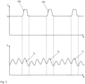
- the curves in Fig. 3 The upper curve shows the position curve ⁇ of a throttle valve over the crankshaft angle curve ⁇ , in which an additional opening ramp OR is periodically inserted.
- the main position ⁇ 0 of the throttle valve does not change over the crankshaft angle ⁇ and the additional opening ramp is periodically inserted in between.
- the main line represents the global actuator position ⁇ 0 and the intermediate ramps OR the relative actuator variations.
- the effects of the relative actuator variations on the pressure curve P in the intake pipe can be adjusted.
- the periodic pulsations of the pressure curve show a changed pressure drop line PA in the area of the relative actuator variations. This changed pressure drop can be used to change the pressure and the intake mass in a cylinder 4 in the intake phase. This allows a gas quantity and/or composition in the fresh air system to be specifically adjusted to reduce consumption and/or emissions.
- the optimal relative actuator variation RA is determined depending on the operating point in tests and/or simulations or by calculations.
- Fig. 4 shows how the relative actuator variation is realized via a torque signal change.
- the upper curve shows in detail the course of the relative actuator variation in the area of the opening ramp OR and the lower curve the torque course required for this.
- the curves show that only relatively short torque pulses MI + are required to accelerate the throttle valve 18 in the direction of additional opening and to slow down this opening movement again by counter-pulses MI - and MI + ; no further torque signal is required to keep it open.
- a torque pulse MI - in the direction of closing the valve is required, and immediately following this, counter-signals MI + and MI - to stop the closing movement again.
- Such momentary pulses MI + and MI - can be carried out very efficiently and with low energy consumption.
- the speed of the position change can be varied as desired using the amplitude of the torque pulses. This means that the change can be implemented either very smoothly (with low torque pulses) or relatively abruptly (with high torque pulses).
Landscapes
- Engineering & Computer Science (AREA)
- Chemical & Material Sciences (AREA)
- Combustion & Propulsion (AREA)
- Mechanical Engineering (AREA)
- General Engineering & Computer Science (AREA)
- Health & Medical Sciences (AREA)
- Biomedical Technology (AREA)
- Output Control And Ontrol Of Special Type Engine (AREA)
Description
- Die vorliegende Erfindung betrifft ein Verfahren zum Betreiben eines Verbrennungsmotors, insbesondere eines Kraftfahrzeugs.
- Verbrennungsmotoren werden mobil, insbesondere bei Straßenfahrzeugen, aber auch bei Luft- und Wasserfahrzeugen eingesetzt sowie stationär für Antriebsaggregate oder zur Energieerzeugung (Kraft-Wärmekopplungseinrichtung).
- Ein Verbrennungsmotor umfasst in der Regel einen Motorblock mit einem oder meist mehreren Zylindern mit hubverstellbaren Kolben (sog. Kolbenmotoren bzw. Hubkolbenmotoren). Die Gaswechselvorgänge in den Zylindern bzw. im Brennraum werden mit Einlass- und Auslassventilen (Gaswechselventile) gesteuert. Zur Frischluftversorgung ist ein Frischluftsystem vorgesehen, welches die Zylinder mit Frischluft versorgt. Typischerweise umfasst ein Frischluftsystem einen Frischluftkanal, einen Frischluftverteiler, von dem einzelne Frischluftrohre zu jeweils einem Zylinder führen.
- Das Abgassystem ist ähnlich aufgebaut, die Abgasströme der einzelnen Zylinder werden über einen Abgaskrümmer gesammelt und über einen Abgaskanal ausgestoßen.
- Bei modernen Motoren sind Frischluftsystem und Abgassystem mechanisch und strömungstechnisch eng miteinander verzahnt. Über Abgasturbolader wird ein Teil der Abgasenergie genutzt, um die zugeführte Frischluft zu verdichten, die Abgasströme selbst können über eine Hochdruckabgasrückführung direkt in den Frischluftstrom abgezweigt werden, in gleicher Weise können auch die einer Abgasnachbehandlung unterzogenen Abgasströme (z.B. Abgaskatalysator, Rußfilter, Stickoxidreduktion) der Frischluft zugeführt werden (Niederdruckabgasrückführung). Sowohl im Frischluftsystem als auch im Abgassystem treten bei Kolbenmaschinen Druckpulsationen auf, die durch die Verbrennungszyklen beim zyklischen Betrieb des Hubkolbenmotors mit den typischen Phasen (Bsp. 4-Takt) Einlassen, Komprimieren, Verbrennen und Auslassen m Zylinder verursacht werden. Dazu gehören auch zyklische Kurzschlüsse des Brennraums zum Frischluft- und Abgassystem während Einlassen und Auslassen und damit verbundene Gasmassentransporte und Druckausgleiche zwischen den kurzgeschlossenen Teilabschnitten.
- Zur Steuerung der Abgas- und Frischluftströme sind unterschiedliche periphere Aktoren vorgesehen. Damit werden im Zusammenhang mit dieser Anmeldung insbesondere Klappen und Ventile wie z.B. die Drosselklappe, VTG-Schaufelwegverstellung (für Turbolader mit verstellbarer Turbinengeometrie), ATL-Wastegate-Ventile, Hochdruckabgasrückführungsventile und Niederdruckabgasrückführungsventile bezeichnet. Diese Aktoren dienen dazu, die vom Motor angesaugte Gasmasse und deren Zusammensetzung aus Frischluft und Abgas einzustellen. Die VTG-Schaufelwegverstellung dient beispielsweise dazu, einen Ladedruck einzustellen, die Drosselklappenverstellung regelt den Saugrohrdruck und damit die angesaugte Gasmenge, ein Abgasrückführungsventil stellt einen rückgeführten AGR-Massenstrom ein und verändert damit die Qualität (Zusammensetzung) und die Quantität (Druck, Temperatur) der dem Brennraum (Zylinder) zugeführten Gasmasse.
- Die angesaugte Gasmasse (beschrieben durch Druck, Temperatur und Zusammensetzung) bestimmt entscheidend die Qualität des Verbrennungsprozesses hinsichtlich des Verbrauches und der resultierenden Emissionen. Beispielsweise werden über die Drosselklappe und die VTG-Stellung das Druckniveau im Saugrohr und im Abgaskrümmer verstellt. Diese beiden Drücke beeinflussen unmittelbar die resultierenden Ladungswechselverluste des Verbrennungsmotors und damit auch den Verbrauch.
- Die sog. Spüldifferenz zwischen diesen beiden Drücken ermöglicht überhaupt eine Abgasrückführung. Die Qualität und die Menge des rückgeführten Abgases beeinflusst die Emissionen als wichtigen zweiten Zielparameter. Die Abgasrückführung kann dabei sowohl intern über die Ladungswechselsteuerorgane (Frisch- und Abgasventile), aber auch ergänzt über Abgasrückführungsventile in der Motorperipherie eingestellt werden.
- Die oben erwähnten Druckpulsationen entstehen durch den Arbeitstakt des Verbrennungsmotors und setzen sich in der Peripherie des Motors fort. Damit variieren über den Arbeitstakt aller Zylinder die Drücke und Massenströme auch in den peripheren Bereichen des Abgassystems und des Frischluftsystems. Diese Pulsationen verändern sich entsprechend den Betriebszuständen des Verbrennungsmotors. Die Aktoren werden in Bezug auf die Pulsationen und im Hinblick auf einen bestimmten Betriebszustand quasi stationär eingestellt, das heißt, sie verändern sich nicht hinsichtlich der Druck- und Volumenpulsationen.
- Es gibt Ansätze, bei denen die Frischluftzufuhr nicht nur betriebszustandsabhängig, sondern verbrennungstaktsynchron optimiert werden soll. Damit ist es im Prinzip möglich, die Frischluftzufuhr nicht nur global, sondern einzeln für jeden Zylinder zu optimieren und anzugleichen. In der
DE 10 2010 061 859 A1 ist dazu ein Ansatz beschrieben, bei dem die Frischluftanlage ein Zusatzventil aufweist, das in einem Frischluftkanal angeordnet ist und so betrieben wird, dass sich Öffnungsphasen, in denen das Zusatzventil den Frischluftkanal öffnet und Schließphasen, in denen das Zusatzventil den Frischluftkanal schließt, abwechseln, wobei die Öffnungsphasen abhängig von einem aktuellen Betriebszustand der Brennkraftmaschine variiert werden, um diese Öffnungsphasen an den aktuellen Betriebszustand anzupassen. Die Anpassung der Öffnungsdauer erfolgt über eine Variation des Schließzeitpunkts dieser Öffnungsphase in Abhängigkeit seiner Phasenlage zum Kurbelwellenwinkel. Damit ist es möglich, die Frischluftzufuhr kurbelwellenwinkelabhängig und gegebenenfalls auch zylinderindividuell einzustellen. Der Ansatz erfordert jedoch ein Zusatzventil, welches zusätzlich zu den bereits vorhandenen oben angegebenen Aktoren erforderlich ist. Das in derDE 10 2010 061 859 angegebene Zusatzventil beruht auf einem Rotationsprinzip, bei dem die Variation stark eingeschränkt ist. Zum einen kann ein solches Ventil nur in "auf" und "zu" eingestellt werden und der Hubverlauf ist nur in engen Grenzen beeinflussbar. Ebenfalls sind die Zeitpunkte für "auf" und "zu" nur in engen Grenzen variierbar. Ein weiteres Beispiel für ein Motorsteuerungssystem ist im DokumentUS 2015/275772 dargestellt. - Aufgabe der vorliegenden Erfindung ist es, ein Verfahren zum Betreiben eines Verbrennungsmotors bereitzustellen, bei dem die oben genannten Nachteile wenigstens teilweise überwunden werden. Eine weitere Aufgabe kann darin gesehen werden, einen Verbrennungsmotor und ein Fahrzeug bereitzustellen, die geeignet sind, entsprechend einem solchen Verfahren betrieben zu werden.
- Diese Aufgabe wird durch das erfindungsgemäße Verfahren nach Anspruch 1, den Verbrennungsmotor nach Anspruch 9 und das Fahrzeug nach Anspruch 10 gelöst. Weitere vorteilhafte Ausgestaltungen der Erfindung ergeben sich aus den Unteransprüchen und der folgenden Beschreibung bevorzugter Ausführungsbeispiele der vorliegenden Erfindung. Das erfindungsgemäße Verfahren zeichnet sich dadurch aus, dass bei wenigstens einem der peripheren Aktoren (siehe oben) neben einer zeitlich mittleren - nachfolgend global benannten - Aktorstellung, die im Hinblick auf einen erfassten Betriebszustand des Verbrennungsmotors eingestellt wird, zusätzlich eine zeitlich relative Aktorvariation ermittelt wird und die globale Aktorstellung um diese relative Aktorvariation verändert wird. Dabei erfolgt die relative Aktorvariation verbrennungstaktsynchron derart, dass eine mittels der Aktorvariation bewirkte Veränderung der Druckpulsation, insbesondere im Frischluftsystem und/oder im Abgassystem, eine Gasmenge bzw. Wunschgasmenge und/oder eine -zusammensetzung im Zylinder, im Frischluftsystem und/oder im Abgassystem verbrauchs- und/oder emissionsminimierend einstellt. Es geht also letztlich darum, durch eine verbrennungstaktsynchrone Relativstellungsaufschaltung um eine betriebspunktabhängige mittlere (globale) Stellung der Aktoren n der Peripherie des Motors die Druckpulsationen zu verändern, um damit die Zielparameter des Verbrennungsprozesses (geringerer Verbrauch, geringere Emissionen) auf ein insgesamt verbessertes Niveau zu heben, da so die Prozesse zylinderindividuell verbessert, angepasst und gleichgestellt werden können.
- Diese so realisierte dynamische Ansteuerung erlaubt eine weitere Optimierung des Verbrennungsprozesses, die mit den klassischen Methoden (WT, Brennverfahrensentwicklung) nicht ohne weiteres realisierbar ist.
- Wird das Verfahren zur optimierten Einstellung und Koordination eines oder mehrerer Aktoren genutzt, sind geringere Kraftstoffverbräuche und reduzierte Emissionen durch Nutzung der sowieso vorhanden Freiheitsgrade des Systems realisierbar. Die verbrennungstaktsynchrone Ansteuerung der Aktoren (Klappen und Ventile) erlaubt außerdem eine Gleichstellung und Optimierung der Arbeitsprozesse in den einzelnen Zylindern (insbesondere hinsichtlich der angesaugten Gasmenge und deren Zusammensetzung).
- So kann beispielsweise eine Optimierung über die verbrennungstaktsynchrone Steuerbarkeit der Abgasrückführungsventile (Hochdruckabgasrückführung, interne Abgasrückführung über die Gaswechselventile und Niederdruckabgasrückführung) durch die Erzeugung bedarfsgerechter Druckgefälle zwischen Abgaskrümmer und Einlasssammler realisiert werden. Die Kombination aus mittlerer Position eines Aktors (globale Aktorstellung) und einem relativen Verlauf (relative Aktorvariation) ermöglicht die Weiternutzung der bestehenden Motorsteuerungsverfahren und deren Ergänzung, um die verbrennungsmotorsynchrone Ansteuerung, auf die ggf. wahlweise auch verzichtet werden kann.
- In einer Ausgestaltung des erfindungsgemäßen Verfahrens ist der jeweilige periphere Aktor als eine Drosselklappe, ein Hochdruckabgasrückführungsventil, ein Niederdruckabgasrückführungsventil, eine VTG-Verstellung und/oder eine Abgasklappe ausgebildet. Diese Aktoren beeinflussen maßgeblich Druck und Zusammensetzung der einzelnen Gasströme im Frischluftsystem und im Abgassystem. Über einen oder mehrere dieser Aktoren lässt sich die Kopplung dieser Systeme (mechanisch und strömungstechnisch) optimieren.
- In einer anderen Weiterbildung des Verfahrens umfasst die relative Aktorvariation einen relativen Sollverlauf, der über ein verbrennungstaktsynchron eingeprägtes Ansteuersignal, insbesondere einen verbrennungstaktsynchron eingeprägten Momentenverlauf des Aktuators beschrieben werden kann. Dabei kann es sich um ein Verstellmoment oder einen Verstellmomentverlauf handeln. Diese Ausführung ist besonders für elektrisch bzw. elektromotorisch angesteuerte Aktoren vorteilhaft. Ein verbrennungstaktsynchrones Verstellmoment bzw. ein relativer Momentenverlauf vereinfacht die energetische Bewertung des Aufwands zur Verstellung, ohne dass dabei hinsichtlich der Güte (Stellgenauigkeit) der resultierenden Positionsveränderungen Abstriche gemacht werden müssen. Dies liegt daran, dass bei Abbrems- und Beschleunigungsphasen bei geringen Positionsunterschieden große Unterschiede im Energieaufwand auftreten können. Demnach wird der klassischen mittleren Sollposition des Aktors (globale Aktorstellung) ein relatives zusätzliches Verstellmoment (relative Aktorvariation) aufgeprägt, um damit den Aktor einer weiteren relativen Beschleunigung und/oder Abbremsung auszusetzen, die zu einer Geschwindigkeitsvariation und damit zu einer Positionsveränderung des Aktors führt. Damit lassen sich die globale Einstellung des Aktors und die relative Variation des Aktors auch steuerungstechnisch besonders elegant überlagern.
- In einer Weiterbildung des Verfahrens erfolgt die Ermittlung der relativen Aktorvariation unter Berücksichtigung wenigstens eines der folgenden Kriterien: Kosten der Aktorvariation, Nutzen der Aktorvariation, Grenzmoment und/der Stromaufnahme einer die Aktorvariation durchführenden Stelleinrichtung. Unter den Kosten der Aktorvariation sind in diesem Zusammenhang nicht nur die Mehrkosten einer zusätzlichen bzw. einer zusätzlich ertüchtigten Stelleinrichtung, sondern auch der erforderliche Energieaufwand zu verstehen, den die zusätzliche relative Aktorvariation erfordert.
- Dem gegenüber gestellt wird der Nutzen der Aktorvariation, der sich letztlich in dem angestrebten reduzierten Verbrauch bzw. der gewünschten oder erforderlichen Reduzierung der Emissionen niederschlägt. Kosten und Nutzen der Aktorvariation können beispielsweise in normierbare Kostenfunktionen gegeneinander abgewogen werden. Solche Funktionen erlauben es auch, über die Nutzungsdauer eines Verbrennungsmotors bzw. eines Fahrzeugs auftretende "Preisveränderungen" zu berücksichtigen und so das Verfahren an sich ändernde Bedingungen anzupassen. "Preis-" bzw. "Kostenänderungen" können z.B. durch geänderte Emissions- bzw. Verbrauchsvorschriften verursacht werden.
- Grenzmoment und/oder Stromaufnahme einer die Aktorvariation durchführenden Stelleinrichtung müssen selbstverständlich auch berücksichtigt werden, um die lebensdauerrelevanten Randbedingungen hinreichend berücksichtigen zu können.
- Ein weiter gebildetes Verfahren, bei welchem die relative Aktorvariation unter Berücksichtigung einer aktuellen Winkelposition des Verbrennungsmotors erfolgt, erlaubt eine besonders einfach Synchronisierung mit dem Verbrennungstakt, da die Kurbelwellenstellung oder auch die Nockenwellenstellung eine erfasste und allzeit verfügbare Prozessgröße darstellt, über die jede Zylinderstellung ableitbar ist und die in engem Zusammenhang mit den zu verändernden globalen und lokalen Druckpulsationen steht.
- In einer Weiterbildung des Verfahrens, bei dem zu jeder Winkelposition eine relative Aktorvariation und/oder ein relativer Aktorvariationsverlauf aus einem Speicher abrufbar ist, lassen sich die gewünschten Aktorvariationen bzw. Aktorvariationsverläufe nutzen, die in Simulationen, Versuchen oder aber auch Berechnungen gewonnen wurden und so über einen Speicher, beispielsweise einer Motorsteuereinheit verfügbar sind. Der Begriff "abrufbar" soll in diesem Zusammenhang nicht dahingehend eingeschränkt werden, dass nur solche Aktorvariationen bzw. Aktorvariationsverläufe nutzbar wären, die bereits fest im Speicher abgelegt sind, sondern der Begriff abrufbar soll auch solche Aktorvariationen bzw. Aktorvariationsverläufe umfassen, die beispielsweise während des Echtzeitbetriebes in einem geeigneten Motorsteuergerät in Abhängigkeit von Eingangssignalen unterschiedlichster Sensoren, von hinterlegten bzw. berechneten Kennfeldern und Betriebspunkten ermittelt und mit Hilfe geeigneter Algorithmen bestimmt werden. Typische Sensorsignale können beispielsweise Drücke und Temperaturen an unterschiedlichen Stellen im Frischluftsystem und/oder im Abgassystem sein sowie Temperaturen im Kühlsystem oder im Kraftstoffsystem bzw. im Ölkreislauf sowie weitere Abgas- und verbrauchsrelevante Signalgrößen.
- In einer spezifischen Ausbildung des Verfahrens werden die Schritte ausgeführt:
Ermitteln einer aktuellen Winkelposition des Verbrennungsmotors, Auslesen einer relativen Aktorvariation und/oder eines relativen Aktorvariationsverlaufes aus dem Speicher und Überlagern der globalen Aktorstellung mit der relativen Aktorvariation und/oder des relativen Aktorvariationsverlaufes in Abhängigkeit von der aktuellen Winkelposition. Dieses Verfahren erlaubt eine besonders elegante Bestimmung und Realisierung der relativen Aktorvariation in Verbindung mit der globalen Aktorstellung. - Bei einer weiteren Verfeinerung des Verfahrens umfasst der Überlagerungsschritt Folgendes:
Umrechnen der relativen Aktorvariation und/oder des relativen Aktorvariationsverlaufes in eine Momentenänderung, Abgleichen der globalen Aktorstellung mit einer Ist-Position des Aktors und Bestimmung einer mittleren Momentenvorgabe, Addieren der Momentenänderung zur mittleren Momentenvorgabe und Ermitteln eines resultierenden Moments, Bestimmen eines Steuersignals aus dem resultierenden Moment und Übermitteln des Steuersignals an den Aktor bzw. eine Stelleinrichtung, welche den Aktor verstellt. - Dieses Verfahren umfasst eine Rückkopplung (Regelungsschleife) der Aktorstellung mit einer Ist-Position des Aktors (die ggf. gefiltert wird, um pulsationsbedingte Schwankungen auszugleichen), so dass nicht nur eine globale Soll-Aktorstellung zur Bestimmung eines resultierenden Momentes herangezogen wird, sondern eine um die Ist-Position korrigierte globale Aktorstellung als Grundlage dient. Das so bestimmte Steuersignal aus dem resultierenden Moment gewährleistet so die notwendige relative Aktorvariation mit minimalem Energieaufwand und damit zu minimalen "Kosten".
- Ein Verbrennungsmotor, der mit einer Steuerung versehen ist, die dazu ausgebildet ist, das erfindungsgemäße Verfahren durchzuführen, erlaubt eine weitere Verbrauchs- und Emissionsoptimierung, ohne dass grundlegende Änderungen des Motorsystems erforderlich wären. Die Optimierungen können auch skalierbar durchgeführt werden, indem zunächst nur ein oder wenige wesentliche Aktoren für eine relative Aktorvariation vorgesehen oder ausgerüstet werden, z.B. beginnend mit der Drosselklappe. Dabei es ist auch möglich, über die Steuerung offenzuhalten, weitere Aktoren für die relative Aktorvariation vorzusehen, um für zukünftige Emissionsvorschriften zusätzliche Aktorvariationen realisierbar zu machen.
- Ein Fahrzeug mit einem Verbrennungsmotor, der dazu ausgebildet ist, das erfindungsgemäße Verfahren durchzuführen, ist bei reduzierten Emissionen bzw. bei reduziertem Kraftstoffverbrauch zu betreiben.
- Ausführungsbeispiele der Erfindung werden nun beispielhaft und unter Bezugnahme auf die beigefügte Zeichnung beschrieben. Darin zeigt:
- Fig. 1
- eine schematische Darstellung eines Fahrzeugs mit einem Verbrennungsmotor und einer Steuerung, die dazu eingerichtet ist, das erfindungsgemäße Verfahren durchzuführen;
- Fig. 2
- eine schematische Darstellung eines Ausführungsbeispiels eines erfindungsgemäßen Verfahrens,
- Fig. 3
- zwei Diagramme, die den Zusammenhang zwischen einer relativen Aktorvariation der Drosselklappe und der Wirkung auf den Saugrohrdruckverlauf zeigen;
- Fig. 4
- ein Diagramm, das den Zusammenhang zwischen der relativen Aktorvariation und einer zugehörigen Momentenvorgabe und
- Fig. 5
- eine Darstellung der Basisschritte des erfindungsgemäßen Verfahrens.
- Die schematische Darstellung in
Fig. 1 zeigt ein Fahrzeug 100 mit einem Verbrennungsmotor 1, der ein Frischluftsystem 2, ein Abgassystem 3 und einen oder mehrere Zylinder 4, denen über ein oder mehrere Einlassventile 5 Frischluft zugeführt wird und aus denen über ein oder mehrere Auslassventile 6 Abgas abgeführt wird. Der angesaugte Frischluftstrom durchläuft zunächst einen Luftfilter 7, wird in einem Verdichterteil eines Abgasturboladers 8 verdichtet. Die Zufuhr der Frischluft wird über die Drosselklappenanordnung 9 geregelt, die einen von mehreren peripheren Aktoren bildet, durchläuft einen Ladeluftkühler 10 und strömt durch ein Einlassventil 5 in den Zylinder 4. - Der Abgasstrom wird durch ein Auslassventil 6 aus dem Zylinder 4 ausgeschoben, treibt die Turbine des Abgasturboladers 8 an, die mit einer variablen Turbinengeometrie und damit mit einer VTG-Verstellung 11 versehen ist, die einen weiteren peripheren Aktor bildet. Der Abgasstrom durchläuft weiter eine Abgasaufbereitung 12 (Katalysator NSC, DPF, etc.) und verlässt durch eine Abgasklappenanordnung 13 das Abgassystem 3.
- Frischluftsystem 2 und Abgassystem 3 sind zum einem primär über die Zylinder 4 mit den Einlass- und Auslassventilen 5 und 6 gekoppelt und sekundär über eine Hochdruckabgasrückführung 14 mit einem Hochdruckabgasrückführungsventil 15 und eine Niederdruckabgasrückführung 16 mit einem Niederdruckabgasrückführungsventil 17. Die Abgasklappenanordnung 13, das Hochdruckabgasrückführungsventil 15 und das Niederdruckabgasrückführungsventil 17 sowie die VTG-Verstellung 11 bilden ebenfalls periphere Aktoren, die über elektrisch ansteuerbare Stelleinrichtungen verstellbar, steuerbar oder aber regelbar sind.
-
Fig. 2 zeigt eine schematische Darstellung eines Ausführungsbeispiels eines erfindungsgemäßen Verfahrens, das in Verbindung mit der Drosselklappenanordnung durchgeführt wird. Zur Durchführung des Verfahrens sind Sensoren erforderlich, die ebenfalls inFig. 1 dargestellt bzw. skizziert sind. Dazu gehören ein Drosselklappenstellungssensor 18, ein Kurbelwellenpositionsgeber19. - Optional können auch weitere Sensoren vorgesehen werden, die beispielsweise zur Steuerung der VTG-Verstellung 11 der Hochabgasrückführung 14, der Niederdruckabgasrückführung 16 und der Abgasklappenanordnung 13 nutzbar sind.
- Alle diese Sensoren geben ihr Signal an ein Motorsteuergerät 20 ab.
- Bei dem Verfahren, das in
Fig. 2 angegeben ist, bestimmt die Motorsteuerung 20 eine gewünschte Drosselklappenstellung, die einer globalen Aktorstellung GA entspricht. In einem Bestimmungsglied 20a der Steuerung 20 wird dabei aus einer Reihe von Fahrzeug- und Betriebszustandsdaten, wie Beschleunigung, Geschwindigkeit, Reibung, Drehmoment, prognostizierter Stellungsverlauf und anderen, eine erreichbare Drosselklappenstellung GAr ermittelt. Diese globale Aktorstellung GA wird in ein Drehmomentsignal MT1 umgerechnet und die erreichbare Drosselklappenstellung GAr wird über eine vom Drosselklappenstellungssensor 18 ermittelte Ist-Stellung DI über ein PI-Element korrigiert und in ein Korrekturdrehmoment MT2 umgewandelt, welches das Drehmomentsignal MT1 korrigiert. Beide zusammen ergeben ein Drehmomentsignal MT, welches zur Einstellung der globalen Aktorstellung der Drosselklappe 9 dient, das Drehmomentsignal wird in einer Servoeinheit S in ein geeignetes Stromsignal umgewandelt, welches eine Stelleinrichtung SE (beispielsweise ein Elektromotor) der Drosselklappenanordnung ansteuert und die Drosselklappe eine gewünschte Stellung einnehmen lässt. - Zur Einstellung einer zusätzlichen relativen Aktorvariation RA (zusätzliche Verstellung der Drosselklappe) wird ein eingephastes Kurbelwellenstellungssignal abgegeben und in Abhängigkeit von der Kurbelwellenstellung und weitere Betriebsgrößen aus einem Kennfeld eine relative Aktorvariation RA bzw. ein relativer Aktorvariationsverlauf RA aus einem Speicherglied 20b der Steuerung 20 abgerufen und in eine Momentenänderung ME umgerechnet. Das Einphasen des Kurbelwellensignals zu einer Drosselklappenschwingung erfolgt über ein optionales Einphasungsglied 20c. Über eine optionale Rampenfunktion RF wird die Änderung ggf. dämpfend ein- bzw. ausgefast. Die Momentenänderung ME, die zu einer relativen Aktorvariation RA führen soll, wird zur mittleren Momentenvorgabe MT addiert, welches so beispielsweise mit einer Änderungsamplitude versehen wird, die dann wunschgemäß im Servo S zu einem entsprechenden elektrischen Signal führt, mit dem der Aktor, hier die Drosselklappe 9, angesteuert wird.
- Diese Ansteuerungskonzept lässt sich auch auf andere Aktoren übertragen. Es ist auch möglich, das Ansteuerungskonzept an mehreren Aktoren gleichzeitig auszuführen und diese Ansteuerungskonzepte untereinander abzustimmen, so dass sehr feingliedrige ergänzende Motorabstimmungen hinsichtlich der Frischluft- und Abgasströme möglich sind.
- Die Kurvenverläufe in
Fig. 3 zeigen in der oberen Kurve den Stellungsverlauf α einer Drosselklappe über den Kurbelwellenwinkelverlauf ϕ, bei der periodisch eine zusätzliche Öffnungsrampe OR eingefügt ist. Die Hauptstellung α0 der Drosselklappe ändert sich über den Kurbelwellenwinkel ϕ nicht und die zusätzliche Öffnungsrampe wird periodisch dazwischen eingefügt. Dabei stellt die Hauptlinie die globale Aktorstellung α0 da und die zwischengeschalteten Rampen OR die relativen Aktorvariationen. - Das in
Figur 2 dargestellte Schema umfasst die inFig. 5 angegebenen Basisschritte des erfindungsgemäßen Verfahrens, insbesondere: - 210 Erfassen eines Betriebszustands des Verbrennungsmotors (1)
- 220 Bestimmen einer globalen Aktorstellung (GA)
- 230 Einstellen der globalen Aktorstellung (GA)
- 240 Ermitteln einer relativen Aktorvariation (RA)
- 250 Verändern der globalen Aktorstellung (GA) um die relative Aktorvariation (RA),
- In der darunter gestellten Kurve sind die Auswirkungen der relativen Aktorvariationen hinsichtlich des Druckverlaufes P im Ansaugrohr verstellbar. Die periodischen Pulsationen des Druckverlaufs zeigen jeweils im Bereich der relativen Aktorvariationen eine veränderte Druckabfallslinie PA. Dieser veränderte Druckabfall ist dazu nutzbar, den Druck und die Ansaugmasse in einem Zylinder 4 in der Ansaugphase zu verändern. Damit kann gezielt eine Gasmenge und/oder eine -zusammensetzung im Frischluftsystem verbrauchs- und/oder emissionsmindernd eingestellt werden. Die dazu optimale relative Aktorvariation RA wird dazu betriebspunktabhängig in Versuchen und/oder Simulationen bzw. durch Berechnungen ermittelt.
-
Fig. 4 zeigt, wie die relative Aktorvariation über eine Momentensignalveränderung realisiert wird. Dabei zeigt die obere Kurve im Detail den Verlauf der relativen Aktorvariation im Bereich der Öffnungsrampe OR und die untere Kurve den dazu erforderlichen Momentenverlauf. Die Kurven zeigen, dass für eine zusätzliche Öffnung nur relative kurze Momentenimpulse MI+ erforderlich sind, um zum einen die Drosselklappe 18 in Richtung zusätzlicher Öffnung zu beschleunigen und diese Öffnungsbewegung durch Gegenimpulse MI- und MI+ wieder abzubremsen, zum Offenhalten ist kein weiteres Momentensignal erforderlich. Zum Wiederschließen ist wiederum ein Momentenimpuls MI- in Richtung Klappe schließen erforderlich, und unmittelbar daran anschließend Gegensignale MI+ und MI-, um die Schließbewegung wieder zu stoppen. - Solche Momentimpulse MI+ und MI- können sehr stromsparend und mit niedrigem Energieaufwand durchgeführt werden.
- Über die Amplitude der Drehmomentimpulse kann die Geschwindigkeit der Stellungsänderung beliebig variiert werden. Das heißt, die Änderung kann entweder sehr weich (mit niedrigem Drehmomentimpulsen) oder auch relativ sprunghaft (mit hohen Drehmomentimpulsen) realisiert werden.
-
- 100
- Fahrzeug
- 1
- Verbrennungsmotor
- 2
- Frischluftsystem
- 3
- Abgassystem
- 4
- Zylinder
- 5
- Einlassventil
- 6
- Auslassventil
- 7
- Luftfilter
- 8
- Abgasturbolader
- 9
- Drosselklappenanordnung
- 10
- Ladeluftkühler
- 11
- VTG-Verstellung
- 12
- Abgasaufbereitung
- 13
- Abgasklappenanordnung
- 14
- Hochdruckabgasrückführung
- 15
- HP-AGR-Ventil
- 16
- Niederdruckabgasrückführung
- 17
- LP-AGR-Ventil
- 18
- Drosselklappenstellungssensor
- 19
- Kurbelwellenwinkelstellungssensor
- 20
- Motorsteuerung
- 20a
- Bestimmungsglied
- 20b
- Speicherglied
- 20c
- Einphasungsglied
- GA
- globale Aktorstellung
- GA,
- erreichbare Aktorstellung
- MT1
- Drehmomentsignal (GA)
- MT2
- Korrekturmoment
- SE
- Stelleinrichtung
- S
- Servoeinheit
- RA
- relative Aktorvariation
- ME
- Momentenänderung
- RF
- Rampenfunktion
- MT
- mittlere Momentenvergabe
- α
- Drosselklappenstellungwinkel
- OR
- Öffnungsrampe
- α0
- globale Aktorstellung (AR)
- P
- Druckverlauf (Ansaugrohr)
- PA
- geänderte Druckabfallslinie
- MI+
- Momentenimpuls
- MI-
- Momentenimpuls
- 210
- Erfassen eines Betriebszustands des Verbrennungsmotors
- 220
- Bestimmen einer globalen Aktorstellung
- 230
- Einstellen der globalen Aktorstellung
- 240
- Ermitteln einer relativen Aktorvariation
- 250
- Verändern der globalen Aktorstellung um die relative Aktorvariation
Claims (10)
- Verfahren zum Betreiben eines Verbrennungsmotors (1), insbesondere eines Kraftfahrzeugs (100), mit mehreren Zylindern (4), einem Frischluftsystem (2) und einem Abgassystem (3), in denen im Betrieb Druckpulsationen auftreten und mit wenigstens einem peripheren Aktor (9, 11, 13, 15, 17) mit:- Erfassen eines Betriebszustands des Verbrennungsmotors (1)- Bestimmen einer globalen Aktorstellung (GA) für den peripheren Aktor (9, 11, 13, 15, 17) basierend auf dem erfassten Betriebszustand des Verbrennungsmotors (1)- Einstellen der globalen Aktorstellung (GA)- Ermitteln einer relativen Aktorvariation (RA) für den peripheren Aktor (9, 11, 13, 15, 17)- Verändern der globalen Aktorstellung (GA) um die relative Aktorvariation (RA),wobei die relative Aktorvariation (RA) verbrennungstaktsynchron derart erfolgt, dass eine mittels der relativen Aktorvariation (RA) bewirkte Veränderung der Druckpulsation eine Wunschgasmenge und/oder eine -zusammensetzung im Zylinder (4), im Frischluftsystem (2) und/oder im Abgassystem (3) verbrauchs- und/oder emissionsminimierend einstellt.
- Verfahren nach Anspruch 1, wobei der wenigstens eine periphere Aktor einen der folgenden umfasst: Drosselklappe (9), Hochdruck-AGR-Ventil (15), Niederdruck-AGR-Ventil (17), VTG-Verstellung (11), Abgasklappe (13).
- Verfahren nach Anspruch 1 oder 2, wobei die relative Aktorvariation (RA) einen relativen Sollverlauf umfasst, der mittels eines verbrennungstaktsynchronen Ansteuersignals, insbesondere ein Verstellmoments (ME, MI+, MI-), einstellbar ist.
- Verfahren nach einem der Ansprüche 1 bis 3, wobei das Ermitteln der relativen Aktorvariation (RA) unter Berücksichtigung eines der folgenden Kriterien erfolgt: Kosten der Aktorvariation, Nutzen der Aktorvariation, Grenzmoment und/oder Stromaufnahme einer die Aktorvariation durchführenden Stelleinrichtung.
- Verfahren nach einem der Ansprüche 1 bis 4, bei welchem die relative Aktorvariation (RA) unter Berücksichtigung einer aktuellen Winkelposition (ϕ) des Verbrennungsmotors erfolgt (1).
- Verfahren nach einem der vorhergehenden Ansprüche, bei welchem zu jeder Winkelposition (ϕ) eine relative Aktorvariation (RA) und/oder ein relativer Aktorvariationsverlauf aus einem Speicher (20b) abrufbar ist.
- Verfahren nach einem der Ansprüchen 1 bis 6 mit:- Ermitteln einer aktuellen Winkelposition (ϕ) des Verbrennungsmotors (1)- Auslesen einer relativen Aktorvariation (RA) und/oder eines relativer Aktorvariationsverlaufes (RA) aus einem Speicher (20b)- Überlagern der globalen Aktorstellung (GA) mit der relativen Aktorvariation (RA) und/oder des relativen Aktorvariationsverlaufes.
- Verfahren nach Anspruch 7, wobei das Überlagern der globalen Aktorstellung (GA) mit der relativen Aktorvariation und/oder des relativen Aktorvariationsverlaufes umfasst:- Umrechnen relativen Aktorvariation (RA) und/oder des relativen Aktorvariationsverlaufes in eine Momentenänderung (ME, MI+, MI-)- Abgleichen der globalen Aktorstellung (GA) mit einer Istposition (DI) des Aktors (9, 11, 13, 14, 17) und Bestimmen einer mittleren Momentenvorgabe (MT)- Addieren der Momentenänderung (ME, MI+, MI-) zur mittleren Momentenvorgabe (MT) und Ermitteln eines resultierenden Moments (ME und MT)- Bestimmen eines Steuersignals aus dem resultierenden Moment und- Übermitteln des Steuersignals an den Aktor.
- Verbrennungsmotor (1) mit einer Steuerung (20, 20a, 20b, 20c), die dazu ausgebildet ist das Verfahren nach einem der vorhergehenden Ansprüche durchzuführen.
- Fahrzeug (100) mit einem Verbrennungsmotor (1) nach Anspruch 9.
Applications Claiming Priority (2)
| Application Number | Priority Date | Filing Date | Title |
|---|---|---|---|
| DE102018206202.1A DE102018206202A1 (de) | 2018-04-23 | 2018-04-23 | Verfahren zum Betreiben eines Verbrennungsmotors |
| PCT/EP2019/059400 WO2019206675A1 (de) | 2018-04-23 | 2019-04-12 | Verfahren zum betreiben eines verbrennungsmotors |
Publications (2)
| Publication Number | Publication Date |
|---|---|
| EP3784892A1 EP3784892A1 (de) | 2021-03-03 |
| EP3784892B1 true EP3784892B1 (de) | 2024-10-16 |
Family
ID=66182575
Family Applications (1)
| Application Number | Title | Priority Date | Filing Date |
|---|---|---|---|
| EP19717869.2A Active EP3784892B1 (de) | 2018-04-23 | 2019-04-12 | Verfahren zum betreiben eines verbrennungsmotors |
Country Status (3)
| Country | Link |
|---|---|
| EP (1) | EP3784892B1 (de) |
| DE (1) | DE102018206202A1 (de) |
| WO (1) | WO2019206675A1 (de) |
Families Citing this family (1)
| Publication number | Priority date | Publication date | Assignee | Title |
|---|---|---|---|---|
| DE102019215617A1 (de) * | 2019-10-11 | 2021-04-15 | Robert Bosch Gmbh | Verfahren zur emissionsbasierten Trajektorienplanung für einen Verbrennungsmotor |
Family Cites Families (10)
| Publication number | Priority date | Publication date | Assignee | Title |
|---|---|---|---|---|
| US20020121266A1 (en) * | 2000-08-31 | 2002-09-05 | Hitachi, Ltd. | Internal combustion engine, and control apparatus and method thereof |
| US6311679B1 (en) * | 2000-05-02 | 2001-11-06 | Ford Global Technologies, Inc. | System and method of controlling air-charge in direct injection lean-burn engines |
| DE10200533B4 (de) * | 2002-01-09 | 2006-04-20 | Robert Bosch Gmbh | Verfahren und Einrichtung zur Unterdruckerzeugung an Verbrennungskraftmaschinen |
| DE102005017410A1 (de) * | 2005-04-15 | 2006-10-19 | Schaeffler Kg | Elektrische Stellvorrichtung zur variablen Betätigung eines Gaswechselventils |
| DE102007003116A1 (de) * | 2007-01-16 | 2008-07-17 | Mahle International Gmbh | Brennkraftmaschinensystem |
| JPWO2008108234A1 (ja) * | 2007-02-20 | 2010-06-10 | トヨタ自動車株式会社 | 内燃機関 |
| WO2008145502A1 (de) * | 2007-05-29 | 2008-12-04 | Mahle International Gmbh | Frischgasventilanordnung in einer brennkraftmaschine |
| DE102010061859A1 (de) | 2010-11-24 | 2012-05-24 | Mahle International Gmbh | Betriebsverfahren |
| DE102010061858A1 (de) * | 2010-11-24 | 2012-05-24 | Mahle International Gmbh | Betriebsverfahren |
| US9599053B2 (en) * | 2014-03-26 | 2017-03-21 | GM Global Technology Operations LLC | Model predictive control systems and methods for internal combustion engines |
-
2018
- 2018-04-23 DE DE102018206202.1A patent/DE102018206202A1/de not_active Withdrawn
-
2019
- 2019-04-12 WO PCT/EP2019/059400 patent/WO2019206675A1/de not_active Ceased
- 2019-04-12 EP EP19717869.2A patent/EP3784892B1/de active Active
Also Published As
| Publication number | Publication date |
|---|---|
| EP3784892A1 (de) | 2021-03-03 |
| WO2019206675A1 (de) | 2019-10-31 |
| DE102018206202A1 (de) | 2019-10-24 |
Similar Documents
| Publication | Publication Date | Title |
|---|---|---|
| EP1576268B1 (de) | Verfahren zum aufheizen eines abgaskatalysators einer mit kraftstoff-direkteinspritzung arbeitenden brennkraftmaschine | |
| DE102005015609B4 (de) | Vorrichtung zum Steuern einer Brennkraftmaschine | |
| DE102007012604B4 (de) | Verfahren zum Regeln einer Einspritzung eines Injektors einer direkteinspritzenden Verbrennungskraftmaschine und direkteinspritzende Verbrennungskraftmaschine | |
| DE102005014735A1 (de) | Multivariable Aktorsteuerung für eine Brennkraftmaschine | |
| EP3698032B1 (de) | Verfahren zur modellbasierten steuerung und regelung einer brennkraftmaschine | |
| DE102014216399B4 (de) | Verfahren und Vorrichtung zum Betreiben eines Verbrennungsmotors mit Abgasrückführung und entsprechendes Motorsystem, Computerprogramm und Speichermedium | |
| DE102013100065A1 (de) | Motor, der eine abgasanlage mit geteiltem strom verwendet, und entsprechende verfahren | |
| EP3783215A1 (de) | Verfahren zur adaption einer erfassten nockenwellenstellung, steuergerät zur durchführung des verfahrens, verbrennungsmotor und fahrzeug | |
| DE102018101434B4 (de) | Steuerungsvorrichtung für einen Verbrennungsmotor | |
| DE102014117213B4 (de) | Temperatursteuerverfahren für einen turboladerkompressor | |
| EP3784892B1 (de) | Verfahren zum betreiben eines verbrennungsmotors | |
| DE202014007678U1 (de) | Turboladersystem | |
| DE10303705B4 (de) | Verfahren zum Betreiben einer mit Kraftstoffdirekteinspritzung arbeitenden Brennkraftmaschine | |
| DE102018101436B4 (de) | Steuerungsvorrichtung für einen Verbrennungsmotor | |
| DE10233951B4 (de) | Verfahren zur Adaption eines Stellstreckenmodells für einen Abgasturboladersteller | |
| WO2018046212A1 (de) | Verfahren und vorrichtung zur steuerung der nach einem gaswechselvorgang im zylinder einer brennkraftmaschine verbleibenden restgasmasse und/oder der während eines gaswechselvorgangs in den abgaskrümmer der brennkraftmaschine gespülten spülluftmasse | |
| DE102017203213B3 (de) | Verfahren und Vorrichtung zur Ventilhubumschaltsteuerung eines Verbrennungsmotors | |
| WO2016078740A1 (de) | Verfahren zum betreiben einer antriebseinrichtung für ein kraftfahrzeug und antriebseinrichtung | |
| DE102016206491A1 (de) | Verfahren und Vorrichtung zum Betreiben eines Verbrennungsmotors mit einem VCR-Steller und zum Überprüfen einer Funktion eines VCR-Stellers | |
| WO2018158089A1 (de) | Verfahren und vorrichtung zur steuerung eines von einem abgasturbolader aufgeladenen verbrennungsmotors | |
| DE102024206062B4 (de) | Steuerungsverfahren, Steuerungsvorrichtung und Computerprogrammprodukt für einen elektrohydraulischen Nockenwellensteller in einem Verbrennungsmotor | |
| DE112018000548T5 (de) | Motorsteuerungen mit direkter Regelung des Zylinderinnen-[O2] | |
| DE102009018735A1 (de) | Abgasrückführung | |
| EP3601772B1 (de) | Verfahren zum betreiben einer brennkraftmaschine und brennkraftmaschine | |
| DE102009024290B4 (de) | Verfahren zum Betreiben einer Brennkraftmaschine |
Legal Events
| Date | Code | Title | Description |
|---|---|---|---|
| STAA | Information on the status of an ep patent application or granted ep patent |
Free format text: STATUS: UNKNOWN |
|
| STAA | Information on the status of an ep patent application or granted ep patent |
Free format text: STATUS: THE INTERNATIONAL PUBLICATION HAS BEEN MADE |
|
| PUAI | Public reference made under article 153(3) epc to a published international application that has entered the european phase |
Free format text: ORIGINAL CODE: 0009012 |
|
| STAA | Information on the status of an ep patent application or granted ep patent |
Free format text: STATUS: REQUEST FOR EXAMINATION WAS MADE |
|
| 17P | Request for examination filed |
Effective date: 20201123 |
|
| AK | Designated contracting states |
Kind code of ref document: A1 Designated state(s): AL AT BE BG CH CY CZ DE DK EE ES FI FR GB GR HR HU IE IS IT LI LT LU LV MC MK MT NL NO PL PT RO RS SE SI SK SM TR |
|
| AX | Request for extension of the european patent |
Extension state: BA ME |
|
| DAV | Request for validation of the european patent (deleted) | ||
| DAX | Request for extension of the european patent (deleted) | ||
| STAA | Information on the status of an ep patent application or granted ep patent |
Free format text: STATUS: EXAMINATION IS IN PROGRESS |
|
| 17Q | First examination report despatched |
Effective date: 20231117 |
|
| GRAP | Despatch of communication of intention to grant a patent |
Free format text: ORIGINAL CODE: EPIDOSNIGR1 |
|
| STAA | Information on the status of an ep patent application or granted ep patent |
Free format text: STATUS: GRANT OF PATENT IS INTENDED |
|
| INTG | Intention to grant announced |
Effective date: 20240708 |
|
| GRAS | Grant fee paid |
Free format text: ORIGINAL CODE: EPIDOSNIGR3 |
|
| GRAA | (expected) grant |
Free format text: ORIGINAL CODE: 0009210 |
|
| STAA | Information on the status of an ep patent application or granted ep patent |
Free format text: STATUS: THE PATENT HAS BEEN GRANTED |
|
| P01 | Opt-out of the competence of the unified patent court (upc) registered |
Free format text: CASE NUMBER: APP_48015/2024 Effective date: 20240821 |
|
| AK | Designated contracting states |
Kind code of ref document: B1 Designated state(s): AL AT BE BG CH CY CZ DE DK EE ES FI FR GB GR HR HU IE IS IT LI LT LU LV MC MK MT NL NO PL PT RO RS SE SI SK SM TR |
|
| REG | Reference to a national code |
Ref country code: GB Ref legal event code: FG4D Free format text: NOT ENGLISH |
|
| REG | Reference to a national code |
Ref country code: CH Ref legal event code: EP Ref country code: DE Ref legal event code: R096 Ref document number: 502019012306 Country of ref document: DE |
|
| REG | Reference to a national code |
Ref country code: IE Ref legal event code: FG4D Free format text: LANGUAGE OF EP DOCUMENT: GERMAN |
|
| REG | Reference to a national code |
Ref country code: LT Ref legal event code: MG9D |
|
| REG | Reference to a national code |
Ref country code: NL Ref legal event code: MP Effective date: 20241016 |
|
| PG25 | Lapsed in a contracting state [announced via postgrant information from national office to epo] |
Ref country code: NL Free format text: LAPSE BECAUSE OF FAILURE TO SUBMIT A TRANSLATION OF THE DESCRIPTION OR TO PAY THE FEE WITHIN THE PRESCRIBED TIME-LIMIT Effective date: 20241016 |
|
| PG25 | Lapsed in a contracting state [announced via postgrant information from national office to epo] |
Ref country code: NL Free format text: LAPSE BECAUSE OF FAILURE TO SUBMIT A TRANSLATION OF THE DESCRIPTION OR TO PAY THE FEE WITHIN THE PRESCRIBED TIME-LIMIT Effective date: 20241016 |
|
| PG25 | Lapsed in a contracting state [announced via postgrant information from national office to epo] |
Ref country code: HR Free format text: LAPSE BECAUSE OF FAILURE TO SUBMIT A TRANSLATION OF THE DESCRIPTION OR TO PAY THE FEE WITHIN THE PRESCRIBED TIME-LIMIT Effective date: 20241016 Ref country code: PT Free format text: LAPSE BECAUSE OF FAILURE TO SUBMIT A TRANSLATION OF THE DESCRIPTION OR TO PAY THE FEE WITHIN THE PRESCRIBED TIME-LIMIT Effective date: 20250217 Ref country code: IS Free format text: LAPSE BECAUSE OF FAILURE TO SUBMIT A TRANSLATION OF THE DESCRIPTION OR TO PAY THE FEE WITHIN THE PRESCRIBED TIME-LIMIT Effective date: 20250216 |
|
| PG25 | Lapsed in a contracting state [announced via postgrant information from national office to epo] |
Ref country code: FI Free format text: LAPSE BECAUSE OF FAILURE TO SUBMIT A TRANSLATION OF THE DESCRIPTION OR TO PAY THE FEE WITHIN THE PRESCRIBED TIME-LIMIT Effective date: 20241016 |
|
| PG25 | Lapsed in a contracting state [announced via postgrant information from national office to epo] |
Ref country code: BG Free format text: LAPSE BECAUSE OF FAILURE TO SUBMIT A TRANSLATION OF THE DESCRIPTION OR TO PAY THE FEE WITHIN THE PRESCRIBED TIME-LIMIT Effective date: 20241016 |
|
| PG25 | Lapsed in a contracting state [announced via postgrant information from national office to epo] |
Ref country code: ES Free format text: LAPSE BECAUSE OF FAILURE TO SUBMIT A TRANSLATION OF THE DESCRIPTION OR TO PAY THE FEE WITHIN THE PRESCRIBED TIME-LIMIT Effective date: 20241016 |
|
| PG25 | Lapsed in a contracting state [announced via postgrant information from national office to epo] |
Ref country code: NO Free format text: LAPSE BECAUSE OF FAILURE TO SUBMIT A TRANSLATION OF THE DESCRIPTION OR TO PAY THE FEE WITHIN THE PRESCRIBED TIME-LIMIT Effective date: 20250116 |
|
| PG25 | Lapsed in a contracting state [announced via postgrant information from national office to epo] |
Ref country code: GR Free format text: LAPSE BECAUSE OF FAILURE TO SUBMIT A TRANSLATION OF THE DESCRIPTION OR TO PAY THE FEE WITHIN THE PRESCRIBED TIME-LIMIT Effective date: 20250117 Ref country code: LV Free format text: LAPSE BECAUSE OF FAILURE TO SUBMIT A TRANSLATION OF THE DESCRIPTION OR TO PAY THE FEE WITHIN THE PRESCRIBED TIME-LIMIT Effective date: 20241016 |
|
| PG25 | Lapsed in a contracting state [announced via postgrant information from national office to epo] |
Ref country code: PL Free format text: LAPSE BECAUSE OF FAILURE TO SUBMIT A TRANSLATION OF THE DESCRIPTION OR TO PAY THE FEE WITHIN THE PRESCRIBED TIME-LIMIT Effective date: 20241016 |
|
| PG25 | Lapsed in a contracting state [announced via postgrant information from national office to epo] |
Ref country code: RS Free format text: LAPSE BECAUSE OF FAILURE TO SUBMIT A TRANSLATION OF THE DESCRIPTION OR TO PAY THE FEE WITHIN THE PRESCRIBED TIME-LIMIT Effective date: 20250116 |
|
| PG25 | Lapsed in a contracting state [announced via postgrant information from national office to epo] |
Ref country code: SM Free format text: LAPSE BECAUSE OF FAILURE TO SUBMIT A TRANSLATION OF THE DESCRIPTION OR TO PAY THE FEE WITHIN THE PRESCRIBED TIME-LIMIT Effective date: 20241016 |
|
| PGFP | Annual fee paid to national office [announced via postgrant information from national office to epo] |
Ref country code: DE Payment date: 20250430 Year of fee payment: 7 |
|
| PG25 | Lapsed in a contracting state [announced via postgrant information from national office to epo] |
Ref country code: DK Free format text: LAPSE BECAUSE OF FAILURE TO SUBMIT A TRANSLATION OF THE DESCRIPTION OR TO PAY THE FEE WITHIN THE PRESCRIBED TIME-LIMIT Effective date: 20241016 |
|
| REG | Reference to a national code |
Ref country code: DE Ref legal event code: R097 Ref document number: 502019012306 Country of ref document: DE |
|
| PG25 | Lapsed in a contracting state [announced via postgrant information from national office to epo] |
Ref country code: EE Free format text: LAPSE BECAUSE OF FAILURE TO SUBMIT A TRANSLATION OF THE DESCRIPTION OR TO PAY THE FEE WITHIN THE PRESCRIBED TIME-LIMIT Effective date: 20241016 |
|
| PG25 | Lapsed in a contracting state [announced via postgrant information from national office to epo] |
Ref country code: RO Free format text: LAPSE BECAUSE OF FAILURE TO SUBMIT A TRANSLATION OF THE DESCRIPTION OR TO PAY THE FEE WITHIN THE PRESCRIBED TIME-LIMIT Effective date: 20241016 |
|
| PG25 | Lapsed in a contracting state [announced via postgrant information from national office to epo] |
Ref country code: SK Free format text: LAPSE BECAUSE OF FAILURE TO SUBMIT A TRANSLATION OF THE DESCRIPTION OR TO PAY THE FEE WITHIN THE PRESCRIBED TIME-LIMIT Effective date: 20241016 |
|
| PG25 | Lapsed in a contracting state [announced via postgrant information from national office to epo] |
Ref country code: CZ Free format text: LAPSE BECAUSE OF FAILURE TO SUBMIT A TRANSLATION OF THE DESCRIPTION OR TO PAY THE FEE WITHIN THE PRESCRIBED TIME-LIMIT Effective date: 20241016 |
|
| PG25 | Lapsed in a contracting state [announced via postgrant information from national office to epo] |
Ref country code: IT Free format text: LAPSE BECAUSE OF FAILURE TO SUBMIT A TRANSLATION OF THE DESCRIPTION OR TO PAY THE FEE WITHIN THE PRESCRIBED TIME-LIMIT Effective date: 20241016 |
|
| PLBE | No opposition filed within time limit |
Free format text: ORIGINAL CODE: 0009261 |
|
| STAA | Information on the status of an ep patent application or granted ep patent |
Free format text: STATUS: NO OPPOSITION FILED WITHIN TIME LIMIT |
|
| PG25 | Lapsed in a contracting state [announced via postgrant information from national office to epo] |
Ref country code: SE Free format text: LAPSE BECAUSE OF FAILURE TO SUBMIT A TRANSLATION OF THE DESCRIPTION OR TO PAY THE FEE WITHIN THE PRESCRIBED TIME-LIMIT Effective date: 20241016 |
|
| 26N | No opposition filed |
Effective date: 20250717 |
|
| REG | Reference to a national code |
Ref country code: CH Ref legal event code: H13 Free format text: ST27 STATUS EVENT CODE: U-0-0-H10-H13 (AS PROVIDED BY THE NATIONAL OFFICE) Effective date: 20251125 |
|
| PG25 | Lapsed in a contracting state [announced via postgrant information from national office to epo] |
Ref country code: LU Free format text: LAPSE BECAUSE OF NON-PAYMENT OF DUE FEES Effective date: 20250412 |
|
| PG25 | Lapsed in a contracting state [announced via postgrant information from national office to epo] |
Ref country code: MC Free format text: LAPSE BECAUSE OF FAILURE TO SUBMIT A TRANSLATION OF THE DESCRIPTION OR TO PAY THE FEE WITHIN THE PRESCRIBED TIME-LIMIT Effective date: 20241016 |
|
| GBPC | Gb: european patent ceased through non-payment of renewal fee |
Effective date: 20250412 |
|
| REG | Reference to a national code |
Ref country code: BE Ref legal event code: MM Effective date: 20250430 |
|
| PG25 | Lapsed in a contracting state [announced via postgrant information from national office to epo] |
Ref country code: GB Free format text: LAPSE BECAUSE OF NON-PAYMENT OF DUE FEES Effective date: 20250412 |
|
| PG25 | Lapsed in a contracting state [announced via postgrant information from national office to epo] |
Ref country code: FR Free format text: LAPSE BECAUSE OF NON-PAYMENT OF DUE FEES Effective date: 20250430 |
|
| PG25 | Lapsed in a contracting state [announced via postgrant information from national office to epo] |
Ref country code: BE Free format text: LAPSE BECAUSE OF NON-PAYMENT OF DUE FEES Effective date: 20250430 |
|
| PG25 | Lapsed in a contracting state [announced via postgrant information from national office to epo] |
Ref country code: CH Free format text: LAPSE BECAUSE OF NON-PAYMENT OF DUE FEES Effective date: 20250430 |
|
| PG25 | Lapsed in a contracting state [announced via postgrant information from national office to epo] |
Ref country code: IE Free format text: LAPSE BECAUSE OF NON-PAYMENT OF DUE FEES Effective date: 20250412 |